US6141337A - Spread spectrum communication system - Google Patents
Spread spectrum communication systemDownload PDFInfo
- Publication number
- US6141337A US6141337AUS08/917,733US91773397AUS6141337AUS 6141337 AUS6141337 AUS 6141337AUS 91773397 AUS91773397 AUS 91773397AUS 6141337 AUS6141337 AUS 6141337A
- Authority
- US
- United States
- Prior art keywords
- signal
- upward
- channel
- master station
- station
- Prior art date
- Legal status (The legal status is an assumption and is not a legal conclusion. Google has not performed a legal analysis and makes no representation as to the accuracy of the status listed.)
- Expired - Lifetime
Links
Images


Classifications
- H—ELECTRICITY
- H04—ELECTRIC COMMUNICATION TECHNIQUE
- H04W—WIRELESS COMMUNICATION NETWORKS
- H04W56/00—Synchronisation arrangements
- H04W56/0055—Synchronisation arrangements determining timing error of reception due to propagation delay
- H04W56/0065—Synchronisation arrangements determining timing error of reception due to propagation delay using measurement of signal travel time
- H04W56/009—Closed loop measurements
- H—ELECTRICITY
- H04—ELECTRIC COMMUNICATION TECHNIQUE
- H04B—TRANSMISSION
- H04B1/00—Details of transmission systems, not covered by a single one of groups H04B3/00 - H04B13/00; Details of transmission systems not characterised by the medium used for transmission
- H04B1/69—Spread spectrum techniques
- H04B1/707—Spread spectrum techniques using direct sequence modulation
- H—ELECTRICITY
- H04—ELECTRIC COMMUNICATION TECHNIQUE
- H04B—TRANSMISSION
- H04B7/00—Radio transmission systems, i.e. using radiation field
- H04B7/24—Radio transmission systems, i.e. using radiation field for communication between two or more posts
- H04B7/26—Radio transmission systems, i.e. using radiation field for communication between two or more posts at least one of which is mobile
- H04B7/2662—Arrangements for Wireless System Synchronisation
- H04B7/2668—Arrangements for Wireless Code-Division Multiple Access [CDMA] System Synchronisation
- H—ELECTRICITY
- H04—ELECTRIC COMMUNICATION TECHNIQUE
- H04J—MULTIPLEX COMMUNICATION
- H04J13/00—Code division multiplex systems
- H04J13/16—Code allocation
Definitions
- the present inventionrelates to a mobile communication system and a mobile terminal, and in particular, to a synchronizing method for synchronizing a spreading code in a reverse or upward communication line to be applied to a reservation code division multiple access (CDMA) packet communication system.
- CDMAreservation code division multiple access
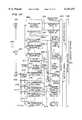
- FIG. 17shows a conventional tranceiver section in a block diagram.
- transmission datais multiplied by a spreading code generated from a PN generator 80.
- the obtained datais transmitted via a high-frequency circuit 404 from an antenna 400a.
- the spreading code generated from the PN generator 80is equal to one symbol and such a code will be called "short code" herebelow.
- a receiver section of a base stationreceives a signal from the mobile terminal.
- the signal received by an antenna 400bis delivered via a high-frequency circuit 403 to be subjected to a correlation process in a matched filter 601.
- an initial acquisition circuit 603detects a preamble 202 of a packet, which will be described later, and then produces a synchronizing signal.
- a packet de-multiplexer 605samples the signal from the filter 601 at a symbol period or for each symbol to produce an associated value.
- the signal outputted from the de-multiplexer 605is demodulated by a detector circuit 607.
- FIG. 2shows a format of packets communicated in the conventional example.
- the packetincludes, as shown in (A) of FIG. 2, a preamble 202a of which each bit is "1", a frame start delimiter 203a to separate the preamble from data, and information data 204a in this order.
- a short code equivalent to the symbol periodis employed as the spreading code.
- a short codeis adopted as the spreading code because of restriction of time required for acquisition.
- interferenceoccurs between the spreading codes and hence the number of communicable terminals is decreased.
- a long codehaving a period of several symbols
- the long coderequires a longer period of time for acquisition.
- the radio channel between a base station and a mobile terminalincludes a plurality of traffic channels to transmit an upward or reverse link data packet (from the mobile terminal to the base station) and a downward or forward link data packet (from the base station to the mobile terminal), a reservation channel to transmit a reservation packet indicating a request for allocation of a traffic channel from the mobile terminal to the base station, and a reply channel to transmit a reply packet indicating a traffic channel for data communication from the base station to the mobile terminal.
- the CDMA spread spectrumis applied to each of the reservation, reply, and traffic channels.
- a mobile terminal having a request for data transmissionsends a reservation packet at timing synchronized with reference timing on the reservation channel.
- the base stationtransmits a reply packet via the reply channel.
- Each mobile terminalcommunicates a data packet at the specified timing via the traffic channel specified by the reply packet.
- a pilot channelis disposed in the downward direction (from the base station to mobile terminals) to transmit via the pilot channel a pilot signal of which each bit is fixed to "0" or "1".
- Each mobile terminalcontinuously keeps synchronization with the pilot signal. Since data packets on each of the downward reply and traffic channels are transmitted in synchronism with the pilot signal, the mobile terminal can despread signals on each of the reply and downward traffic channels in accordance with the timing of pilot signal kept synchronized with the mobile terminal.
- each of the reply, traffic, and pilot channelsis assigned with a unique long code (a pseudo noise (PN) is assigned as the spreading code) and the reservation channel is assigned with a short code.
- PNpseudo noise
- the mobile terminalestablishes transmission reference timing for the reservation and upward traffic channels according to the pilot signal.
- the point of timing of arrival at the base station of the reservation and upward traffic packets sent from the mobile terminal in synchronism with the reference timingis delayed relative to the reference timing of the base station for a period of propagation delay due to the distance of upward and downward packet propagation between the mobile terminal and the base station.
- the base stationdespreads by a matched filter (MF), which changes a coefficient with the symbol period, the signals spread according to the long code. Consequently, when the timing difference exceeds the one-symbol time between the reception timing of the upward traffic packet and that of the base station due to the propagation delay, the despreading process cannot be normally accomplished, namely, the signals cannot be demodulated.
- MFmatched filter
- a short codeis allocated to the reservation channel because it is unnecessary to alter the matched filter coefficient.
- the base stationidentifies by the matched filter the signals of a plurality of reservation packets sent from the plural mobile terminals, the packets being overlapped with each other with respect to time.
- the base stationthen conducts bit signal processing for each packet and measures the propagation delay time thereof. Using the measured delay time, the reception timing of the upward traffic packet is adjusted with the one-symbol precision to thereby accomplish the despreading process at a high speed for the upward traffic channel to which the long code is allocated.
- the propagation delay time measured on the reservation channelis used to predict the packet propagation delay time for the upward traffic channel so as to achieve the high-speed acquisition by the matched filter for traffic channel which changes the coefficient for each symbol or with the symbol period.
- the propagation delay time measured on the reservation channelis notified via the reply channel to the pertinent mobile terminal. According to the propagation delay time, the mobile terminal then corrects the transmission timing of the upward traffic packet to achieve the high-speed acquisition by a matched filter for traffic channel, the filter changing the coefficient with the symbol period.
- the traffic channel receiver of the base stationincludes a packet de-multiplexer and a mixer.
- signals which are sent via a multiple channel and which are overlapped in time with each otherare detected and are mixed with each other to thereby carry out a RAKE reception. This resultantly improves the probability of acquisition and the signal-to-noise ratio.
- FIG. 1is a diagram for explaining operation of the first embodiment according to the present invention
- FIG. 2is a diagram showing the layout of the reservation packet of the present invention
- FIG. 3is a diagram showing the layout of the traffic packet of the present invention.
- FIG. 4is a block diagram showing the configuration of a base station in the first embodiment of the CDMA mobile communication system according to the present invention
- FIG. 5is a block diagram showing the configuration of a mobile terminal in the first embodiment of the CDMA mobile communication system according to the resent invention
- FIG. 6is a diagram showing the configuration of a reservation channel receiver of the base station
- FIG. 7is a diagram showing the configuration of a traffic channel receiver of the base station
- FIG. 8is a diagram showing the configuration of a matched filter
- FIG. 9is a diagram showing the configuration of an initial acquisition circuit in the channel receiver.
- FIG. 10is a diagram showing the configuration of a packet de-multiplexer in the channel receiver
- FIG. 11is a schematic diagram showing operation of the packet de-multiplexer
- FIG. 12is a diagram showing the configuration of a propagation delay measuring circuit in the reservation channel receiver
- FIG. 13is a diagram for explaining operation of the second embodiment according to the present invention.
- FIG. 14is a block diagram showing the configuration of a base station in the second embodiment of the CDMA mobile communication system according to the present invention.
- FIG. 15is a block diagram showing the configuration of a mobile terminal in the second embodiment of the CDMA mobile communication system according to the present invention.
- FIG. 16is a block diagram showing another configuration of a traffic channel receiver in the base station of the CDMA mobile communication system according to the present invention.
- FIG. 17is a diagram showing the configuration of a transmitter-receiver in conventional technology.
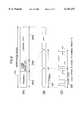
- FIG. 1is a diagram for explaining the reception timing of an upward traffic packet.
- the packetis transmitted in synchronism with a predetermined point of reference timing.
- the base stationcontinuously transmits pilot signals spread in spectrum according to a PN sequence having an appropriate period on the downward communication line.
- Each mobile terminalmonitors the pilot signals to extract a synchronizing (reference) signal so as to synchronize with a reply signal and a downward traffic signal from the base station.
- a synchronizing (reference) signalso as to synchronize with a reply signal and a downward traffic signal from the base station.
- due to the propagation distancethere appears a difference in time between frame timing 102 of the base station and frame timing 103 of the mobile terminal. Therefore, when the base station receives a reservation packet 104 sent from the mobile terminal, there exists propagation delay time ⁇ t1 associated with the distance.
- the base stationreceives, according to a scheduling algorithm specified by the reply packet 105, an upward or reverse link traffic packet 107 sent from the mobile station.
- the base stationstarts receiving the traffic packet 107 when ⁇ t1 lapses after a reference point of time 106.
- FIG. 2shows the layout of the reservation packet and the spreading code allocated thereto.
- the packet and the codeare the same as those of the prior art and hence will not be described.
- FIG. 3shows the layout of the traffic packet and the spreading code allocated thereto.
- the traffic packetincludes a preamble 202b of which each bit is "1", a frame start delimiter 203b to separate the preamble from data, and information data 204b in this order beginning at the first point of the packet.
- FIG. 3 (C)shows the spreading code allocated to the traffic packet. The period of spreading code thus allocated is equal to that of the traffic packet.
- the traffic packet 105considerably varies from the reservation packet 104. Namely, looking at one symbol 205 in the traffic packet, it is to be appreciated that the symbol 205 is spread by a spreading code which is different from that used for the other symbols.
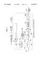
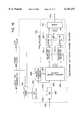
- FIG. 4is a diagram showing an example of the configuration of the base station in a CDMA radio communication system to which the present invention is applied.
- the base stationis connected via a network interface 422 to a mobile communication network 423.
- a packet controller 419receives a transmission signal 421 from the network interface 422 and then sends a reply signal 513 or a downward (forward link) traffic signal 514 to the pertinent mobile terminal.
- the packet controller 419receives an upward (reverse link) traffic signal 515 and then sends a received signal 420 to the network interface 422.
- the packet controller 419obtains a reservation signal 516 on the received reservation channel to schedule data transmission to a terminal having a request for data transmission. The scheduling is accomplished by sending a reply signal to the mobile terminal having transmitted the reservation signal.
- a clock generator 411generates a chip clock signal 414.
- the chip clock 414is employed as a clock signal for a PN generator (long code) 415 and the like.
- a clock divider 412divides the chip clock 414 generated from the clock generator 411 to produce a symbol clock signal 413.
- a frame clock signal 408generated from the PN generator 415 for the pilot signal, which will be described later.
- the base stationsends a pilot signal 512, a reply signal 513, and a downward traffic signal 514. These signals are respectively multiplied by spreading codes (long codes) generated respectively from the PN generators 415, 416, and 471-1 to 471-m, the spreading codes being mutually synchronized with each other. The resultant signals are added to each other by adders. The superimposed signal is then transformed into a signal having a carrier frequency by a high-frequency circuit 403 to be transmitted via a circulator 401 from an antenna 400. Moreover, the PN generator 415 for the pilot signal generates a frame clock signal 408 having a period of the long spreading code.
- a signal received by the antenna 400is inputted via the circulator 401 to a high-frequency circuit 402 to be converted into a base-band spread spectrum signal.
- the base-band signal 404is supplied to a reservation channel receiver 405 and traffic channel receivers 409-1 to 409-m.
- the reservation channel receiver 405separates a reservation signal from the base-band signal 404 so as to output the reservation signal to the packet controller 419 and a function to output propagation delay information 407 of each reservation packet to the traffic channel receiver 409 corresponding thereto.
- the traffic channel receiver 409receives the propagation delay information 407 from the reservation channel receiver 405 to predict reception timing of a traffic packet to be received.
- the traffic channel receiver 409demodulates the base-band signal 404 according to the predicted reception timing to produce an upward traffic signal 515.
- the signal 515is then fed to the packet controller 419.
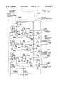
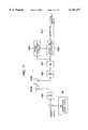
- FIG. 5shows an example of the configuration of a mobile terminal related to the base state shown in FIG. 4.
- a signal received by an antenna 400is inputted via a circulator 401 to a high-frequency circuit 403 to be demodulated into a base-band spread spectrum signal.
- the signalis multiplied by multipliers by PN (long) codes respectively generated from PN generators 415 to 417 of the respective channels. Namely, a despreading process is conducted for the signal.
- the signals thus obtainedare accumulated for a fixed period of time by an accumulator 506 to be demodulated into received data.
- a reply signal 513 and a downward traffic signal 514 in the packet formatare transformed by a packet controller 419 into original data to be sent as a received signal 420 to a user interface 510.
- the user interface 510conducts signal processing for the received signal 420 and then outputs the obtained signal to an input/output interface 511.
- the user interface 510Conversely, when a signal is inputted from the interface 511, the user interface 510 accordingly outputs a transmission signal 421 to the packet controller 419.
- the controller 419then transmits a reservation signal 516 to the base station to notify the request for transmission.
- a response from the base stationis notified by a reply signal 513.
- Reading the reply signal 513the packet controller 419 transmits, according to a scheduling algorithm indicated by the base station, an upward traffic signal 515 including a packet of the transmission signal 421.
- the pilot signal 512is continuously transmitted from the base station.
- a delay lock loop (DLL) controller 507keeps synchronization according to the pilot signal.
- DLLdelay lock loop
- the DLL controllergenerates a system clock signal 506 to be inputted to the respective PN generators (only the PN generator 415 is shown in FIG. 5).
- the system clock 506is equivalent to the chip clock in the base station and is used to establish synchronization between operations respectively of the base station and the mobile terminal.
- the PN generator (long code) 415 for despreading the pilot signalgenerates a frame clock signal 509 having a period of the long code.
- the frame clock 509is fed to the reset terminal of each PN generator to synchronize PN generators (long code) 416, 417, 504, and 505 with each other.
- the upward or reverse link traffic signal 515is multiplied by a multiplier by a spreading code (long code) generated from the PN generator 504, i.e., a spectrum spreading process is carried out for the signal 515.
- the reservation signal 516is multiplied by a multiplier by a spreading code (long code) generated from the PN generator 505, i.e., a spectrum spreading process is carried out for the signal 516.
- the upward traffic signal and the reservation signal having the spreading processare then added by an adder to each other to be transmitted via a high-frequency circuit 404 and a circulator 401 from an antenna 400.
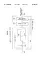
- FIG. 6shows the configuration of the reservation channel receiver 405.
- the receiver 405despreads the base-band signal 404 inputted thereto to produce reservation signals 406-1 to 406-m. Additionally, the receiver 405 measures the values of propagation delay time 407-1 to 407-m of the respectively multiplexed reservation packets.
- the base-band signal 404is transformed by a matched filter 601 into a signal of correlation value 602.
- the output signal 602is inputted to an initial acquisition circuit 603 and a packet de-multiplexer 605.
- the acquisition circuit 603establishes the chip synchronization in association with the preamble field of the packet to produce a chip synchronization timing signal 604.
- the de-multiplexer 605de-multiplexes the correlation value signal 602 to separate from each other the packets overlapped in time with each other.
- the values of chip timing 58-1 to 58-m and received signals 59-1 to 59-m of the separated packetsare fed to propagation delay measuring circuits 606-1 to 606-m, respectively.
- the circuit 606measures the propagation delay time of each separated packet according to the frame clock 408 to produce information of propagation delay time 407. Detectors 607-1 to 607-m respectively detect the separated packets to thereby demodulate the reservation signals 406.
- FIG. 7shows the configuration of the traffic channel receiver 409.
- the receiver 409despreads the inputted base-band signal 404 to produce a traffic signal 410.
- the despreading processis conducted according to the information of propagation delay time of the reservation packet transmitted from the same mobile terminal.
- a timer 701sets the information of propagation delay 407 to its initial value and then receives the chip clock 414 to decrement the value.
- the timer 701activates the PN selector 702.
- the matched filter of the reservation channel receiver 405uses the short code PN sequence and hence operates with a fixed coefficient
- the matched filter of the traffic channel receiver 409uses the long code PN sequence and it is therefore required to alter the coefficient thereof for each symbol.
- the PN selector 702is provided to vary the coefficient of the matched filter.
- the PN selector 702outputs a PN signal (spread code coefficient) 704 and a matched filter coefficient load signal 703 to the matched filter 601 to set the spread code for the traffic channel to the coefficient of the filter 601 for each symbol period.
- the initial acquisition circuit 603 of the traffic channel receiver 409is the same as that of the reservation channel receiver 405.
- a packet de-multiplexer 605'is responsive to the chip synchronization timing signal 604 generated from the initial acquisition circuit 603 to sample for each symbol period signals outputted from the matched filter and then outputs a chip timing signal 58 and a received signal 59 of the separated packet to a delimiter detector 705.
- the delimiter detector 705detects a frame start delimiter 203b in the packet configured as shown in FIG. 3 to input only control or information data 204b to a detector 608.
- the detector 608detects each separated packet to produce a traffic signal 410.
- FIG. 8shows the fundamental configuration of the matched filter 601.
- the filter 601includes a plurality of cascaded delay elements 801 which each have delay time t equal to the chip duration of PN sequence, a plurality of coefficient registers 805, a plurality of coefficient delay elements 806, and a plurality of coefficient multipliers 802 respectively connected to an input tap of an initial stage and output taps of the respective delay elements.
- a signal 404 inputted to the filter 601is propagated sequentially through the delay elements 801. When the signals 404 outputted from the taps match the value set to the coefficient register 805, the outputs from the respective coefficient multipliers 802 have the same sign.
- the matched filter of FIG. 8has a function to receive the matched filter coefficient load signal 703 and the PN signal 704 from the PN selector 702 shown in FIG. 7 to thereby update the values of the coefficient registers 805.
- the coefficient delay element 806reads the PN code from the PN selector 702 in a code-by-code fashion to deliver the code thereto.
- FIG. 9shows the detailed configuration of the initial acquisition circuit 603.
- the circuit 603includes a cyclic adder 901, a threshold comparator 904, and a time window processing unit 905.
- the cyclic adder 901includes an adder 902 and a delay element 903.
- the element 903has delay time Ts set to a period of time equal to one symbol.
- the delay element 903has a reset terminal to receive the frame clock 408 so as to be cleared for each frame of the packet.
- the correlation value 602 outputted from the matched filter 601is added by the adder 902 to the signal advanced one symbol in time and then the result is inputted again to the delay element 903.
- the correlation value 602 associated with the preamble field of which each bit is "1"is cyclically added as described above.
- the threshold comparator 904decides whether or not the output from the adder 902 exceeds the threshold value. Only when the threshold value is exceeded, the threshold comparator 904 is turned on (state of "1").
- the time window processing unit 905validates the output signal from the comparator 904 only during a period of time in which the preamble 202 of the packet can be received according to the frame clock 408 (the predicted propagation delay time and the reception period of preamble field) to output the signal as a chip synchronization timing signal 604 therefrom.
- FIG. 10shows an example of the construction of the packet de-multiplexer 605.
- the chip synchronization timing signal 604 attained from the initial acquisition circuit 603is inputted to an AND gate 50.
- the AND gate 50has another input terminal which is off in the initial state. Due to the inverted or negation signals inputted thereto, the AND gate 50 is opened by the signal outputted from the comparator to set the output signal from the gate 50 to the on state ("1"). The on signal from the AND gate 50 is then fed to AND gates 52a and 53a.
- the AND gate 53aincludes another input receiving an inverted signal of an output signal from a register 51a.
- the output from the register 51ais off ("0"). Therefore, when the output from the AND gate 50 is set to the on state, the output from the AND gate 53a is also set to the on state.
- the on state ("1") of the AND circuit 53ais inputted as an enable signal to a timing generator 54a.
- the value of a counter 60 at this momentis set to a timing register 54a as a value to indicate the acquisition timing.
- the counter 60conducts the counting operation with the chip period of the PN code. In the counting operation, when the reset input of the symbol clock 41 is received, the counter 60 is restored to the initial value according to the symbol period to conduct the counting operation.
- the on signal from the AND gate 53asets a register 51a to the on state, the register 51a controlling other inputs of the AND gates 52a and 53a.
- the register 51akeeps the on state until the register 51a is reset by the frame clock 408 at the initial point of the next frame.
- the register 51akeeps the AND gate 53 in the closed state to prevent another value from being set to the timing register 54a.
- the acquisition timing value set to the timing register 54ais compared by a comparator 55a with the signal outputted from the counter 60.
- the comparator 55ais set to the on state.
- the on-state signal outputted from the comparator 55ais inputted to an enable terminal of a data register 57a via an AND gate 56a which is in the open state when the register 51a is on.
- the signal outputted from the matched filter at the acquisition timingis inputted to the data register 57a and is then outputted therefrom as a received signal 59a.
- the on signal from the AND gate 50is sent via the AND gate set to the open state by the output from the register 51a and the AND gate 53b set to the open state by the output from the register 51b to an enable terminal of a timing register 54b in the subsequent stage. Resultantly, the value outputted from the counter 60 is set to the timing register 54b. At this time, the register 51b is set to the on state and prevents, through an operation similar to that of the register 51a in the preceding stage, another value from being set to the register 54b until the frame is terminated.
- the timing registers 54a to 54c of the respective stagesoperate in a mutually similar manner such that the output signal from the matched filter corresponding to each reservation packet is kept in the associated data register 57a, 57b, or 57c for each symbol.
- the signalsare then outputted therefrom as received signals 59a to 59c, respectively.
- the example of FIG. 10includes the timing registers 54a to 54c in the three-stage structure. Consequently, three acquisition timing values can be memorized for three leading packets selected in the generation order from a plural packets generated in an overlapped manner with respect to time.
- FIG. 11shows in a schematic diagram a specific example of the de-multiplexing operation.
- three packets for which the spreading process is conducted with a process gain set to 3 and of which the packet length is five symbolsare de-multiplexed by the circuit configuration shown in FIG. 10.
- the outputs of chip synchronization timing signal 604 from the initial acquisition circuit 603are denoted as 62aa to 62ae (packet 61a), 62ba to 62be (packet 61b), and 62ca to 62ce (packet 61c).
- the outputs from the AND gates 53a to 53care indicated as 63a to 63c, respectively.
- the outputs from the registers 51a to 51care respectively represented as 64a to 64c.
- the outputs from the timing registers 54a to 54care denoted as 66a to 66c, respectively.
- the outputs from the AND gates 56a to 56care respectively indicated as 67a to 67c.
- the timing register 54aWhen the output signal 63a is received from the AND gate 53a, the timing register 54a is loaded with the value "2" (65a) from the counter 60. Thereafter, the AND gate 56a produces an on-state signal at a timing when the output value 66a from the timing register 54a is equal to that from the counter 60 (67a).
- the timing registers 54b and 54care respectively loaded with the values "3" (65b) and "1" (65c) from the counter 60. Thereafter, the AND gates 56b and 56c produce on-state signals as the outputs 67b and 67c at timing when the output values 66b and 66c from the timing registers 56b and 56c each become equal to that from the counter 60 (67b, 67c).
- FIG. 12shows the configuration of the propagation delay measuring circuit 606.
- a delimiter detector 705detects the frame start delimiter 203 in the packet configured as shown in FIGS. 2 and 3 to output only the information data 204 as received data.
- the circuit 705notifies a propagation delay accumulator 71 with the timing of detection of the delimiter 203.
- the accumulator 71measures the propagation delay time in the one-symbol unit or for each symbol.
- a symbol counter 70is a counter which is reset at the first point of each frame and which conducts the counting operation in the symbol unit. The accumulator 71 obtains the delay of the packet for each symbol according to the value of the symbol counter 70.
- the point of time when the delimiter is detectedis used as a reference point of the operation.
- the propagation delay time of the packet detected for each symbol by the propagation delay accumulator 71is added to the propagation delay time of the packet attained in the chip unit or for each chip by the packet de-multiplexer 605 (i.e., the output from the timing register 54 of FIG. 10).
- the period of time required for the processing in the receiveris then subtracted from the result of the addition to thereby produce the delay time information 407 of the traffic packet.
- FIGS. 13 to 15shows the second embodiment according to the present invention.
- FIG. 13is a diagram for explaining the reception timing of the upward or reverse link traffic packet in the second embodiment.
- the base stationstarts the despreading process at a point of timing when a predetermined maximum delay ⁇ tmax lapses after the reference point of timing.
- the base stationmeasures delay time ⁇ t2 and subtracts the delay time from the maximum delay time ⁇ tmax to produce a delay control signal representing the resultant value, i.e., ⁇ tmax- ⁇ t2.
- the control signalis notified to the mobile terminal by the reply packet 105'.
- the mobile terminaldecodes the delay control signal in the reply packet to transmit an upward traffic packet when the time ( ⁇ tmax- ⁇ t2) indicated by the delay control signal lapses after the reference point of timing. Thanks to the correction of delay by the mobile terminal, the base station can initiates receiving the upward traffic packet 107 at timing delayed ⁇ tmax relative to the reference timing.
- FIG. 14shows the configuration of the base station in the second embodiment.
- the delay time information 407 measured according to the reservation packetis passed to the mobile terminal by the reply signal 513.
- the mobile terminalcorrects the propagation delay to send data with the corrected delay via the upward traffic channel.
- the same circuit constituent elements as those of FIG. 4are assigned with the same reference numerals and achieve the same functions as those of FIG. 4.
- the delay time information 407 measured by the reservation channel receiver 405is subtracted from the maximum delay time 450 to attain the delay control signal 451.
- the signal 451is mixed with a reply signal 513 by a mixer 452 to be transmitted to the mobile terminal.
- the propagation delay of the packetis virtually equal to the maximum delay time 450.
- a PN selector 702 of each of the traffic channel receivers 409-1 to 409-minitiates its operation.
- FIG. 15shows the construction of the mobile terminal in the second embodiment.
- the same circuit constituent elements of FIG. 15 as those of FIG. 5are assigned with the same reference numerals and achieve the same functions as those of FIG. 5.
- a delay control signal decoder 550obtains a delay control signal from the reply signal 513 to output the control signal to a delay controller 552.
- the delay controller 552delays the data for a period of time relative to the reference timing indicated by a frame clock 509, the period of time being indicated by the delay control signal 551.
- FIG. 16shows another example of the configuration of the reservation traffic channel receiver 409. Applied to a reverse link traffic receiver 409 shown in FIG. 16 is the RAKE reception. Also in FIG. 16, the same circuit constituent elements as those of FIG. 7 are assigned with the same reference numerals and achieve the same functions as those of FIG. 7. According to this configuration example, as in the reservation channel receiver 405, packets overlapped in time with each other are de-multiplexed or separated from each other by a packet de-multiplexer 605 in the traffic channel receiver 409. The de-multiplexed signals from the de-multiplexer 605 are mixed with each other by a RAKE receiver 750.
- the receiver 750includes a plurality of delimiter detectors 701-1 to 701-n and detectors 607'-1 to 607'-n. Signal of each separated packet from the de-multiplexer 605 are detected to be mixed with each other by a mixer 757.
Landscapes
- Engineering & Computer Science (AREA)
- Computer Networks & Wireless Communication (AREA)
- Signal Processing (AREA)
- Mobile Radio Communication Systems (AREA)
- Dc Digital Transmission (AREA)
Abstract
Description
Claims (6)
Applications Claiming Priority (2)
| Application Number | Priority Date | Filing Date | Title |
|---|---|---|---|
| JP29482696AJP3323760B2 (en) | 1996-11-07 | 1996-11-07 | Spread spectrum communication system |
| JP8-294826 | 1996-11-07 |
Publications (1)
| Publication Number | Publication Date |
|---|---|
| US6141337Atrue US6141337A (en) | 2000-10-31 |
Family
ID=17812761
Family Applications (1)
| Application Number | Title | Priority Date | Filing Date |
|---|---|---|---|
| US08/917,733Expired - LifetimeUS6141337A (en) | 1996-11-07 | 1997-08-27 | Spread spectrum communication system |
Country Status (4)
| Country | Link |
|---|---|
| US (1) | US6141337A (en) |
| JP (1) | JP3323760B2 (en) |
| KR (1) | KR19980041834A (en) |
| CN (1) | CN1182314A (en) |
Cited By (28)
| Publication number | Priority date | Publication date | Assignee | Title |
|---|---|---|---|---|
| US6301286B1 (en)* | 1999-03-22 | 2001-10-09 | Golden Bridge Technology, Inc. | Common packet channel |
| US20010033604A1 (en)* | 2000-02-14 | 2001-10-25 | Matsushita Electric Industrial Co., Ltd. | Pilot signal reception method and receiver |
| US6512785B1 (en)* | 1998-02-12 | 2003-01-28 | Yozan Inc. | Matched filter bank |
| US6574267B1 (en) | 1999-03-22 | 2003-06-03 | Golden Bridge Technology, Inc. | Rach ramp-up acknowledgement |
| US6606341B1 (en) | 1999-03-22 | 2003-08-12 | Golden Bridge Technology, Inc. | Common packet channel with firm handoff |
| US20030198212A1 (en)* | 2002-04-19 | 2003-10-23 | General Electric Company | Method and apparatus for synchronizing a radio telemetry system by way of transmitted-reference , delay-hopped ultra-wideband pilot signal |
| US20030206556A1 (en)* | 2002-05-01 | 2003-11-06 | International Business Machines Corporation | Method, system, and article of manufacture for data transmission |
| US6785321B1 (en)* | 2000-10-31 | 2004-08-31 | Motorola, Inc. | Apparatus and method for estimating the time of arrival of a spread spectrum signal in a wireless communication system |
| US20040264554A1 (en)* | 1998-09-09 | 2004-12-30 | Harms Brian K | User terminal parallel searcher |
| EP0986195A3 (en)* | 1998-09-11 | 2005-04-27 | Nec Corporation | Spread spectrum communication method and spread spectrum communication apparatus |
| US20050088996A1 (en)* | 2003-10-24 | 2005-04-28 | Ntt Docomo, Inc. | Wireless communications system and method using transmission timing control |
| US20050163066A1 (en)* | 2001-01-26 | 2005-07-28 | At&T Corp. | Method for packet-switching interface for code division switching in a terrestrial wireless system |
| US20050202837A1 (en)* | 2002-07-31 | 2005-09-15 | Yoichi Tanabe | Wireless base station, wireless frames synchronization detection method used therein, and recording medium on which program therefor is recorded |
| US7050466B1 (en)* | 1999-10-05 | 2006-05-23 | Lg Electronics Inc. | Apparatus and method for acquiring multi-user signal synchronization in code division multiple access system |
| US20060280228A1 (en)* | 1999-07-30 | 2006-12-14 | Norbert Daniele | Data transmission using repeated sets of spreading sequences |
| US20090041094A1 (en)* | 2005-10-03 | 2009-02-12 | Daiji Ishii | Signal receiving apparatus including equalizer, terminal apparatus, signal receiving method, and signal receiving program |
| US20100157975A1 (en)* | 2008-12-18 | 2010-06-24 | Samsung Electronics Co., Ltd. | Method and system for performing time synchronization between nodes in wireless communication system |
| US20110135300A1 (en)* | 2008-07-03 | 2011-06-09 | Ntt Docomo, Inc. | Radio base station equipment, radio communication system and delay correction method |
| US8446893B2 (en)* | 2006-12-21 | 2013-05-21 | Samsung Electronics Co., Ltd. | Enhanced coexistence beacon protocol (ECBP) for precise intercell synchronization of overlapping wireless base stations |
| US20130279612A1 (en)* | 2010-09-30 | 2013-10-24 | France Telecom | Noise limitation for transmission in a multi-path channel |
| US20140301428A1 (en)* | 2011-12-15 | 2014-10-09 | Eutelsat S A | Transmission/reception of microwave signals broadcast by a satellite with an interactive return link using a spread spectrum protocol |
| US9661528B2 (en) | 2004-12-23 | 2017-05-23 | Electronic And Telecommunications Research Institute | Apparatus for transmitting and receiving data to provide high-speed data communication and method thereof |
| US10003377B1 (en) | 2016-12-19 | 2018-06-19 | Cisco Technology, Inc. | Spread spectrum acoustic communication techniques |
| US10141973B1 (en) | 2017-06-23 | 2018-11-27 | Cisco Technology, Inc. | Endpoint proximity pairing using acoustic spread spectrum token exchange and ranging information |
| US10305536B2 (en) | 1999-05-31 | 2019-05-28 | Electronics And Telecommunications Research Institute | Apparatus and method for modulating data message by employing orthogonal variable spreading factor (OVSF) codes in mobile communication system |
| US10396846B1 (en) | 2018-10-12 | 2019-08-27 | Cisco Technology, Inc. | Adaptive decoding of spread spectrum signals using multiple correlator peaks |
| US10404319B1 (en) | 2018-07-09 | 2019-09-03 | Cisco Technology, Inc. | Fast correlation of prometheus orthonormal sets (PONS) for communications |
| US10601459B1 (en) | 2018-11-02 | 2020-03-24 | Cisco Technology, Inc. | Efficient handling of clock offset in spread spectrum decoders |
Families Citing this family (6)
| Publication number | Priority date | Publication date | Assignee | Title |
|---|---|---|---|---|
| AR018668A1 (en) | 1998-06-13 | 2001-11-28 | Samsung Electronics Co Ltd | METHOD FOR CONTROLLING CHANNEL ACCESS THROUGH RESERVATION OF ACCESS SLOTS IN A MOBILE COMMUNICATION SYSTEM |
| JP2001016159A (en)* | 1999-06-28 | 2001-01-19 | Fujitsu Ltd | Base station and mobile station |
| KR100429189B1 (en)* | 1999-08-27 | 2004-04-28 | 엘지전자 주식회사 | Method for assigning common packet channel efficiently |
| JP5140300B2 (en) | 2007-03-23 | 2013-02-06 | 株式会社エヌ・ティ・ティ・ドコモ | Mobile station, radio base station, and synchronization establishment method |
| JP2012100143A (en)* | 2010-11-04 | 2012-05-24 | National Institute Of Information & Communication Technology | Two channel network system |
| CN107342793B (en)* | 2016-04-28 | 2021-06-29 | 松下知识产权经营株式会社 | Power transmitting device, power receiving device, and power transmission system |
Citations (23)
| Publication number | Priority date | Publication date | Assignee | Title |
|---|---|---|---|---|
| US4905221A (en)* | 1987-08-24 | 1990-02-27 | Nec Corporation | Earth station capable of effectively using a frequency band of a satellite |
| US5111479A (en)* | 1989-11-02 | 1992-05-05 | Clarion Co., Ltd. | Spread spectrum receiver and carrier sense circuit therefor |
| US5400359A (en)* | 1992-03-23 | 1995-03-21 | Sharp Kabushiki Kaisha | Spread spectrum communication system and an apparatus for communication utilizing this system |
| US5495498A (en)* | 1993-07-27 | 1996-02-27 | Matsushita Electric Industrial Co., Ltd. | Spread spectrum communication apparatus |
| US5638362A (en)* | 1993-10-14 | 1997-06-10 | Ntt Mobile Communications Network, Inc. | Correlation detector and communication apparatus |
| US5673260A (en)* | 1994-02-09 | 1997-09-30 | Ntt Mobile Communications Network Inc. | Method and system for CDMA mobile communication |
| US5689525A (en)* | 1994-08-11 | 1997-11-18 | Matsushita Electric Industrial Co., Ltd. | Direct-sequence spread-spectrum communication system |
| US5703873A (en)* | 1994-05-30 | 1997-12-30 | Nokia Telecommunications Oy | Method and apparatus for synchronizing subscriber equipment with base stations in a CDMA radio network |
| US5703902A (en)* | 1995-06-16 | 1997-12-30 | Qualcomm Incorporated | Method and apparatus for determining signal strength in a variable data rate system |
| US5712871A (en)* | 1993-06-14 | 1998-01-27 | Chang; Chen-Yi | Method and apparatus for implementing a direct-sequence code division multiple access communication system with an M-ary pulse-position modulated spreading-sequence signal |
| US5715244A (en)* | 1994-11-25 | 1998-02-03 | Samsung Electronics Co., Ltd. | Receiving apparatus for a base station in a code division multiple access system and signal receiving method therefor |
| US5724378A (en)* | 1994-12-13 | 1998-03-03 | Nit Mobile Communications Network, Inc. | CDMA multiuser receiver and method |
| US5748687A (en)* | 1995-06-30 | 1998-05-05 | Interdigital Technology Corp. | Spreading code sequence acquisition system and method that allows fast acquisition in code division multiple access (CDMA) systems |
| US5790588A (en)* | 1995-06-07 | 1998-08-04 | Ntt Mobile Communications Network, Inc. | Spread spectrum transmitter and receiver employing composite spreading codes |
| US5802046A (en)* | 1995-06-05 | 1998-09-01 | Omnipoint Corporation | Efficient time division duplex communication system with interleaved format and timing adjustment control |
| US5835489A (en)* | 1994-01-31 | 1998-11-10 | Matsushita Electric Industrial Co., Ltd. | CDMA communication system |
| US5859612A (en)* | 1996-06-06 | 1999-01-12 | Qualcomm Incorporated | Method for using an antenna with a rotating beam for determining the position of a mobile subscriber in a CDMA cellular telephone system |
| US5872810A (en)* | 1996-01-26 | 1999-02-16 | Imec Co. | Programmable modem apparatus for transmitting and receiving digital data, design method and use method for said modem |
| US5878076A (en)* | 1995-05-12 | 1999-03-02 | U.S. Philips Corporation | Direct-sequence spread spectrum communication system, a primary radio station, and a secondary radio station |
| US5943361A (en)* | 1990-06-25 | 1999-08-24 | Qualcomm Incorporated | System and method for generating signal waveforms in a CDMA cellular telephone system |
| US5943329A (en)* | 1995-09-11 | 1999-08-24 | Hitachi, Ltd. | Code division multiple access mobile communication system |
| US5974082A (en)* | 1996-10-28 | 1999-10-26 | Kokusai Denshin Denwa Co., Ltd. | Spread spectrum communications system |
| US6034635A (en)* | 1996-06-06 | 2000-03-07 | Gilhousen; Klein S. | Method for using only two base stations for determining the position of a mobile subscriber in a CDMA cellular telephone system |
- 1996
- 1996-11-07JPJP29482696Apatent/JP3323760B2/ennot_activeExpired - Lifetime
- 1997
- 1997-08-27KRKR1019970041484Apatent/KR19980041834A/ennot_activeCeased
- 1997-08-27USUS08/917,733patent/US6141337A/ennot_activeExpired - Lifetime
- 1997-08-28CNCN97117529Apatent/CN1182314A/enactivePending
Patent Citations (24)
| Publication number | Priority date | Publication date | Assignee | Title |
|---|---|---|---|---|
| US4905221A (en)* | 1987-08-24 | 1990-02-27 | Nec Corporation | Earth station capable of effectively using a frequency band of a satellite |
| US5111479A (en)* | 1989-11-02 | 1992-05-05 | Clarion Co., Ltd. | Spread spectrum receiver and carrier sense circuit therefor |
| US5943361A (en)* | 1990-06-25 | 1999-08-24 | Qualcomm Incorporated | System and method for generating signal waveforms in a CDMA cellular telephone system |
| US5400359A (en)* | 1992-03-23 | 1995-03-21 | Sharp Kabushiki Kaisha | Spread spectrum communication system and an apparatus for communication utilizing this system |
| US5712871A (en)* | 1993-06-14 | 1998-01-27 | Chang; Chen-Yi | Method and apparatus for implementing a direct-sequence code division multiple access communication system with an M-ary pulse-position modulated spreading-sequence signal |
| US5495498A (en)* | 1993-07-27 | 1996-02-27 | Matsushita Electric Industrial Co., Ltd. | Spread spectrum communication apparatus |
| US5638362A (en)* | 1993-10-14 | 1997-06-10 | Ntt Mobile Communications Network, Inc. | Correlation detector and communication apparatus |
| US5835489A (en)* | 1994-01-31 | 1998-11-10 | Matsushita Electric Industrial Co., Ltd. | CDMA communication system |
| US5673260A (en)* | 1994-02-09 | 1997-09-30 | Ntt Mobile Communications Network Inc. | Method and system for CDMA mobile communication |
| US5703873A (en)* | 1994-05-30 | 1997-12-30 | Nokia Telecommunications Oy | Method and apparatus for synchronizing subscriber equipment with base stations in a CDMA radio network |
| US5689525A (en)* | 1994-08-11 | 1997-11-18 | Matsushita Electric Industrial Co., Ltd. | Direct-sequence spread-spectrum communication system |
| US5715244A (en)* | 1994-11-25 | 1998-02-03 | Samsung Electronics Co., Ltd. | Receiving apparatus for a base station in a code division multiple access system and signal receiving method therefor |
| US5724378A (en)* | 1994-12-13 | 1998-03-03 | Nit Mobile Communications Network, Inc. | CDMA multiuser receiver and method |
| US5878076A (en)* | 1995-05-12 | 1999-03-02 | U.S. Philips Corporation | Direct-sequence spread spectrum communication system, a primary radio station, and a secondary radio station |
| US5802046A (en)* | 1995-06-05 | 1998-09-01 | Omnipoint Corporation | Efficient time division duplex communication system with interleaved format and timing adjustment control |
| US5790588A (en)* | 1995-06-07 | 1998-08-04 | Ntt Mobile Communications Network, Inc. | Spread spectrum transmitter and receiver employing composite spreading codes |
| US5703902A (en)* | 1995-06-16 | 1997-12-30 | Qualcomm Incorporated | Method and apparatus for determining signal strength in a variable data rate system |
| US5748687A (en)* | 1995-06-30 | 1998-05-05 | Interdigital Technology Corp. | Spreading code sequence acquisition system and method that allows fast acquisition in code division multiple access (CDMA) systems |
| US5799010A (en)* | 1995-06-30 | 1998-08-25 | Interdigital Technology Corporation | Code division multiple access (CDMA) communication system |
| US5943329A (en)* | 1995-09-11 | 1999-08-24 | Hitachi, Ltd. | Code division multiple access mobile communication system |
| US5872810A (en)* | 1996-01-26 | 1999-02-16 | Imec Co. | Programmable modem apparatus for transmitting and receiving digital data, design method and use method for said modem |
| US5859612A (en)* | 1996-06-06 | 1999-01-12 | Qualcomm Incorporated | Method for using an antenna with a rotating beam for determining the position of a mobile subscriber in a CDMA cellular telephone system |
| US6034635A (en)* | 1996-06-06 | 2000-03-07 | Gilhousen; Klein S. | Method for using only two base stations for determining the position of a mobile subscriber in a CDMA cellular telephone system |
| US5974082A (en)* | 1996-10-28 | 1999-10-26 | Kokusai Denshin Denwa Co., Ltd. | Spread spectrum communications system |
Non-Patent Citations (3)
| Title |
|---|
| "A Demodulation for Direct-Sequence Spread ALOHA System", Technical Report of the Institute of Electronics Information and Communication Engineers A ·P95-10 (1995-04), pp. 67-74. |
| A Demodulation for Direct Sequence Spread ALOHA System , Technical Report of the Institute of Electronics Information and Communication Engineers A P95 10 (1995 04), pp. 67 74.* |
| U.S. Ser. No. 08/690,819 filed on Aug. 1, 1996.* |
Cited By (54)
| Publication number | Priority date | Publication date | Assignee | Title |
|---|---|---|---|---|
| US6512785B1 (en)* | 1998-02-12 | 2003-01-28 | Yozan Inc. | Matched filter bank |
| US20040264554A1 (en)* | 1998-09-09 | 2004-12-30 | Harms Brian K | User terminal parallel searcher |
| EP0986195A3 (en)* | 1998-09-11 | 2005-04-27 | Nec Corporation | Spread spectrum communication method and spread spectrum communication apparatus |
| US7508861B2 (en) | 1999-03-22 | 2009-03-24 | Golden Bridge Technology, Inc. | RACH ramp-up acknowledgement |
| US6996155B2 (en) | 1999-03-22 | 2006-02-07 | Golden Bridge Technology, Inc. | Common packet channel |
| US20080062951A1 (en)* | 1999-03-22 | 2008-03-13 | Golden Bridge Technology, Inc | Collision detection |
| US7359427B2 (en) | 1999-03-22 | 2008-04-15 | Golden Bridge Technology, Inc. | Rach ramp-up acknowledgement |
| US6717975B2 (en) | 1999-03-22 | 2004-04-06 | Golden Bridge Technology, Inc. | Common packet channel |
| US20090161635A1 (en)* | 1999-03-22 | 2009-06-25 | Golden Bridge Technology, Inc. | Rach-ramp-up acknowledgement |
| US6574267B1 (en) | 1999-03-22 | 2003-06-03 | Golden Bridge Technology, Inc. | Rach ramp-up acknowledgement |
| US6606341B1 (en) | 1999-03-22 | 2003-08-12 | Golden Bridge Technology, Inc. | Common packet channel with firm handoff |
| US8718150B2 (en) | 1999-03-22 | 2014-05-06 | Golden Bridge Technology, Inc. | RACH-ramp-up acknowledgement |
| US6301286B1 (en)* | 1999-03-22 | 2001-10-09 | Golden Bridge Technology, Inc. | Common packet channel |
| US6985511B2 (en) | 1999-03-22 | 2006-01-10 | Golden Bridge Technology, Inc. | Common packet channel with firm handoff |
| US10305536B2 (en) | 1999-05-31 | 2019-05-28 | Electronics And Telecommunications Research Institute | Apparatus and method for modulating data message by employing orthogonal variable spreading factor (OVSF) codes in mobile communication system |
| US7933311B2 (en)* | 1999-07-30 | 2011-04-26 | Commissariat A L'energie Atomique | Data transmission using repeated sets of spreading sequences |
| US20060280228A1 (en)* | 1999-07-30 | 2006-12-14 | Norbert Daniele | Data transmission using repeated sets of spreading sequences |
| US7050466B1 (en)* | 1999-10-05 | 2006-05-23 | Lg Electronics Inc. | Apparatus and method for acquiring multi-user signal synchronization in code division multiple access system |
| US6977956B2 (en)* | 2000-02-14 | 2005-12-20 | Matsushita Electric Industrial Co., Ltd. | Pilot signal reception method and receiver |
| US20010033604A1 (en)* | 2000-02-14 | 2001-10-25 | Matsushita Electric Industrial Co., Ltd. | Pilot signal reception method and receiver |
| US6785321B1 (en)* | 2000-10-31 | 2004-08-31 | Motorola, Inc. | Apparatus and method for estimating the time of arrival of a spread spectrum signal in a wireless communication system |
| US20050163066A1 (en)* | 2001-01-26 | 2005-07-28 | At&T Corp. | Method for packet-switching interface for code division switching in a terrestrial wireless system |
| US7656837B2 (en)* | 2001-01-26 | 2010-02-02 | Diakoumis Parissis Gerakoulis | Method for packet-switching interface for code division switching in a terrestrial wireless system |
| US7313127B2 (en)* | 2002-04-19 | 2007-12-25 | General Electric Company | Method and apparatus for synchronizing a radio telemetry system by way of transmitted-reference, delay-hopped ultra-wideband pilot signal |
| US20030198212A1 (en)* | 2002-04-19 | 2003-10-23 | General Electric Company | Method and apparatus for synchronizing a radio telemetry system by way of transmitted-reference , delay-hopped ultra-wideband pilot signal |
| US20090122796A1 (en)* | 2002-05-01 | 2009-05-14 | International Business Machines Corporation | System and article of manufacture for data transmission |
| US7103006B2 (en) | 2002-05-01 | 2006-09-05 | International Business Machines Corporation | Method, system, and article of manufacture for data transmission |
| US7778198B2 (en) | 2002-05-01 | 2010-08-17 | International Business Machines Corporation | System and article of manufacture for data transmission |
| US20030206556A1 (en)* | 2002-05-01 | 2003-11-06 | International Business Machines Corporation | Method, system, and article of manufacture for data transmission |
| US20050202837A1 (en)* | 2002-07-31 | 2005-09-15 | Yoichi Tanabe | Wireless base station, wireless frames synchronization detection method used therein, and recording medium on which program therefor is recorded |
| US7508796B2 (en) | 2002-07-31 | 2009-03-24 | Nec Corporation | Wireless base station, wireless frames synchronization detection method used therein, and recording medium on which program therefor is recorded |
| US7647060B2 (en)* | 2003-10-24 | 2010-01-12 | Ntt Docomo, Inc. | Wireless communications system and method using transmission timing control |
| US20050088996A1 (en)* | 2003-10-24 | 2005-04-28 | Ntt Docomo, Inc. | Wireless communications system and method using transmission timing control |
| US9661528B2 (en) | 2004-12-23 | 2017-05-23 | Electronic And Telecommunications Research Institute | Apparatus for transmitting and receiving data to provide high-speed data communication and method thereof |
| US20090041094A1 (en)* | 2005-10-03 | 2009-02-12 | Daiji Ishii | Signal receiving apparatus including equalizer, terminal apparatus, signal receiving method, and signal receiving program |
| US8018986B2 (en)* | 2005-10-03 | 2011-09-13 | Nec Corporation | Signal receiving apparatus including equalizer, terminal apparatus, signal receiving method, and signal receiving program |
| US8446893B2 (en)* | 2006-12-21 | 2013-05-21 | Samsung Electronics Co., Ltd. | Enhanced coexistence beacon protocol (ECBP) for precise intercell synchronization of overlapping wireless base stations |
| US20110135300A1 (en)* | 2008-07-03 | 2011-06-09 | Ntt Docomo, Inc. | Radio base station equipment, radio communication system and delay correction method |
| US8224386B2 (en)* | 2008-07-03 | 2012-07-17 | Ntt Docomo, Inc. | Radio base station equipment, radio communication system and delay correction method |
| US20100157975A1 (en)* | 2008-12-18 | 2010-06-24 | Samsung Electronics Co., Ltd. | Method and system for performing time synchronization between nodes in wireless communication system |
| US8705508B2 (en) | 2008-12-18 | 2014-04-22 | Samsung Electronics Co., Ltd. | Method and system for performing time synchronization between nodes in wireless communication system |
| US9219552B2 (en)* | 2010-09-30 | 2015-12-22 | France Telecom | Noise limitation for transmission in a multi-path channel |
| US20130279612A1 (en)* | 2010-09-30 | 2013-10-24 | France Telecom | Noise limitation for transmission in a multi-path channel |
| US20140301428A1 (en)* | 2011-12-15 | 2014-10-09 | Eutelsat S A | Transmission/reception of microwave signals broadcast by a satellite with an interactive return link using a spread spectrum protocol |
| US9838751B2 (en)* | 2011-12-15 | 2017-12-05 | Eutelsat S A | Transmission/reception of microwave signals broadcast by a satellite with an interactive return link using a spread spectrum protocol |
| US10003377B1 (en) | 2016-12-19 | 2018-06-19 | Cisco Technology, Inc. | Spread spectrum acoustic communication techniques |
| US10530417B2 (en) | 2016-12-19 | 2020-01-07 | Cisco Technology, Inc. | Spread spectrum acoustic communication techniques |
| US10141973B1 (en) | 2017-06-23 | 2018-11-27 | Cisco Technology, Inc. | Endpoint proximity pairing using acoustic spread spectrum token exchange and ranging information |
| USRE49288E1 (en) | 2017-06-23 | 2022-11-08 | Cisco Technology, Inc. | Endpoint proximity pairing using acoustic spread spectrum token exchange and ranging information |
| US10404319B1 (en) | 2018-07-09 | 2019-09-03 | Cisco Technology, Inc. | Fast correlation of prometheus orthonormal sets (PONS) for communications |
| US10530418B1 (en) | 2018-07-09 | 2020-01-07 | Cisco Technology, Inc. | Fast correlation of prometheus orthonormal sets (PONS) for communications |
| US10396846B1 (en) | 2018-10-12 | 2019-08-27 | Cisco Technology, Inc. | Adaptive decoding of spread spectrum signals using multiple correlator peaks |
| US10601459B1 (en) | 2018-11-02 | 2020-03-24 | Cisco Technology, Inc. | Efficient handling of clock offset in spread spectrum decoders |
| US11005521B2 (en) | 2018-11-02 | 2021-05-11 | Cisco Technology, Inc. | Efficient handling of clock offset in spread spectrum decoders |
Also Published As
| Publication number | Publication date |
|---|---|
| KR19980041834A (en) | 1998-08-17 |
| CN1182314A (en) | 1998-05-20 |
| JPH10145329A (en) | 1998-05-29 |
| JP3323760B2 (en) | 2002-09-09 |
Similar Documents
| Publication | Publication Date | Title |
|---|---|---|
| US6141337A (en) | Spread spectrum communication system | |
| US6269075B1 (en) | Finger assignment in a CDMA rake receiver | |
| EP1057279B1 (en) | method for asynchronous cdma cellular communication | |
| US7916699B2 (en) | CDMA communication system and method | |
| US6085104A (en) | Pilot aided, time-varying finite impulse response, adaptive channel matching receiving system and method | |
| USRE38523E1 (en) | Spreading code sequence acquisition system and method that allows fast acquisition in code division multiple access (CDMA) systems | |
| KR20050056931A (en) | Communications in an asynchronous wireless network | |
| US5699380A (en) | Spread spectrum communication terminal apparatus in CDMA cellular telephone system | |
| GB2331901A (en) | Rake receiver finger management for spread spectrum communication | |
| WO2005053258A2 (en) | Method and apparatus of frequency estimation for the downlink of td-scdma systems | |
| KR100355327B1 (en) | Communication terminal apparatus and radio communication method | |
| US6954447B2 (en) | Method and apparatus for uplink synchronization in wireless communications | |
| AU2035301A (en) | Synchronization of diversity handover destination base station | |
| EP1134916B1 (en) | Method for acquisition of slot timing in a direct sequence spread spectrum communication receiver | |
| CA2273659A1 (en) | Channel estimation apparatus and communication terminal apparatus | |
| KR20020035175A (en) | Cdma receiver, and reception method | |
| CN100367818C (en) | Mobile communication system and method, mobile terminal, base station | |
| US6895038B2 (en) | Communication system | |
| JP4628591B2 (en) | Spreading code generation circuit and demodulation circuit | |
| JP2003347968A (en) | Path position detecting method and cdma receiver | |
| JP2000115029A (en) | Spread spectrum communication system | |
| EP0903869A2 (en) | Clock regenerating circuit in direct sequence spread spectrum communication system | |
| JPH06197096A (en) | Mobile communication system | |
| JP2877243B2 (en) | Spread spectrum communication receiver | |
| JPH0758665A (en) | Reception method and device for spread spectrum communications |
Legal Events
| Date | Code | Title | Description |
|---|---|---|---|
| AS | Assignment | Owner name:HITACHI, LTD., JAPAN Free format text:ASSIGNMENT OF ASSIGNORS INTEREST;ASSIGNORS:UTA, TAKAKI;YANO, TAKASHI;DOI, NOBUKAZU;REEL/FRAME:010976/0666 Effective date:19971016 | |
| STCF | Information on status: patent grant | Free format text:PATENTED CASE | |
| FEPP | Fee payment procedure | Free format text:PAYOR NUMBER ASSIGNED (ORIGINAL EVENT CODE: ASPN); ENTITY STATUS OF PATENT OWNER: LARGE ENTITY | |
| FPAY | Fee payment | Year of fee payment:4 | |
| AS | Assignment | Owner name:HITACHI COMMUNICATION TECHNOLOGIES, LTD., JAPAN Free format text:ASSIGNMENT OF ASSIGNORS INTEREST;ASSIGNOR:HITACHI, LTD.;REEL/FRAME:019795/0750 Effective date:20070427 | |
| AS | Assignment | Owner name:FIPA FROHWITTER INTELLECTUAL PROPERTY AG, GERMANY Free format text:ASSIGNMENT OF ASSIGNORS INTEREST;ASSIGNOR:HITACHI COMMUNICATION TECHNOLOGIES, LTD.;REEL/FRAME:020352/0061 Effective date:20080111 Owner name:FIPA FROHWITTER INTELLECTUAL PROPERTY AG,GERMANY Free format text:ASSIGNMENT OF ASSIGNORS INTEREST;ASSIGNOR:HITACHI COMMUNICATION TECHNOLOGIES, LTD.;REEL/FRAME:020352/0061 Effective date:20080111 | |
| FPAY | Fee payment | Year of fee payment:8 | |
| FPAY | Fee payment | Year of fee payment:12 |