US6141145A - Stereo panoramic viewing system - Google Patents
Stereo panoramic viewing systemDownload PDFInfo
- Publication number
- US6141145A US6141145AUS09/141,867US14186798AUS6141145AUS 6141145 AUS6141145 AUS 6141145AUS 14186798 AUS14186798 AUS 14186798AUS 6141145 AUS6141145 AUS 6141145A
- Authority
- US
- United States
- Prior art keywords
- view
- image processing
- processing devices
- field
- virtual optical
- Prior art date
- Legal status (The legal status is an assumption and is not a legal conclusion. Google has not performed a legal analysis and makes no representation as to the accuracy of the status listed.)
- Expired - Lifetime
Links
Images


Classifications
- G—PHYSICS
- G03—PHOTOGRAPHY; CINEMATOGRAPHY; ANALOGOUS TECHNIQUES USING WAVES OTHER THAN OPTICAL WAVES; ELECTROGRAPHY; HOLOGRAPHY
- G03B—APPARATUS OR ARRANGEMENTS FOR TAKING PHOTOGRAPHS OR FOR PROJECTING OR VIEWING THEM; APPARATUS OR ARRANGEMENTS EMPLOYING ANALOGOUS TECHNIQUES USING WAVES OTHER THAN OPTICAL WAVES; ACCESSORIES THEREFOR
- G03B37/00—Panoramic or wide-screen photography; Photographing extended surfaces, e.g. for surveying; Photographing internal surfaces, e.g. of pipe
- G03B37/04—Panoramic or wide-screen photography; Photographing extended surfaces, e.g. for surveying; Photographing internal surfaces, e.g. of pipe with cameras or projectors providing touching or overlapping fields of view
- G—PHYSICS
- G02—OPTICS
- G02B—OPTICAL ELEMENTS, SYSTEMS OR APPARATUS
- G02B30/00—Optical systems or apparatus for producing three-dimensional [3D] effects, e.g. stereoscopic images
- G02B30/20—Optical systems or apparatus for producing three-dimensional [3D] effects, e.g. stereoscopic images by providing first and second parallax images to an observer's left and right eyes
- G—PHYSICS
- G03—PHOTOGRAPHY; CINEMATOGRAPHY; ANALOGOUS TECHNIQUES USING WAVES OTHER THAN OPTICAL WAVES; ELECTROGRAPHY; HOLOGRAPHY
- G03B—APPARATUS OR ARRANGEMENTS FOR TAKING PHOTOGRAPHS OR FOR PROJECTING OR VIEWING THEM; APPARATUS OR ARRANGEMENTS EMPLOYING ANALOGOUS TECHNIQUES USING WAVES OTHER THAN OPTICAL WAVES; ACCESSORIES THEREFOR
- G03B17/00—Details of cameras or camera bodies; Accessories therefor
- G03B17/02—Bodies
- G03B17/17—Bodies with reflectors arranged in beam forming the photographic image, e.g. for reducing dimensions of camera
- G—PHYSICS
- G03—PHOTOGRAPHY; CINEMATOGRAPHY; ANALOGOUS TECHNIQUES USING WAVES OTHER THAN OPTICAL WAVES; ELECTROGRAPHY; HOLOGRAPHY
- G03B—APPARATUS OR ARRANGEMENTS FOR TAKING PHOTOGRAPHS OR FOR PROJECTING OR VIEWING THEM; APPARATUS OR ARRANGEMENTS EMPLOYING ANALOGOUS TECHNIQUES USING WAVES OTHER THAN OPTICAL WAVES; ACCESSORIES THEREFOR
- G03B37/00—Panoramic or wide-screen photography; Photographing extended surfaces, e.g. for surveying; Photographing internal surfaces, e.g. of pipe
- H—ELECTRICITY
- H04—ELECTRIC COMMUNICATION TECHNIQUE
- H04N—PICTORIAL COMMUNICATION, e.g. TELEVISION
- H04N5/00—Details of television systems
- H04N5/222—Studio circuitry; Studio devices; Studio equipment
- H04N5/262—Studio circuits, e.g. for mixing, switching-over, change of character of image, other special effects ; Cameras specially adapted for the electronic generation of special effects
- H04N5/2624—Studio circuits, e.g. for mixing, switching-over, change of character of image, other special effects ; Cameras specially adapted for the electronic generation of special effects for obtaining an image which is composed of whole input images, e.g. splitscreen
- H—ELECTRICITY
- H04—ELECTRIC COMMUNICATION TECHNIQUE
- H04N—PICTORIAL COMMUNICATION, e.g. TELEVISION
- H04N7/00—Television systems
- H04N7/18—Closed-circuit television [CCTV] systems, i.e. systems in which the video signal is not broadcast
- H04N7/181—Closed-circuit television [CCTV] systems, i.e. systems in which the video signal is not broadcast for receiving images from a plurality of remote sources
Definitions
- the present inventionrelates to a viewing system; more particularly, a panoramic viewing system.
- Telepresencerefers to providing visual or other types of sensory information from a device at a remote site to a user that makes the user feel as if he/she is present at the remote site. For example, many businesses now hold meetings using telepresence. Telepresence is also useful for distance learning and remote viewing of events such as concerts and sporting events. A more realistic telepresence is provided to a user by providing the user with the capability to switch between views, and thereby mimic, for example, looking around a meeting room.
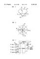
- FIG. 1illustrates cameras 2, 4, 6, and 8 with optical centers 10, 12, 14, and 16, respectively.
- FIG. 1illustrates cameras 2, 4, 6, and 8 with optical centers 10, 12, 14, and 16, respectively.
- the userdecided to change views, he or she simply switched between cameras.
- a userdecided to change views, he or she was able to obtain a view from optical centers 10, 12, 14, or 16 as well as from additional optical centers 18, 20, 22, 24, or 26.
- Views associated with optical centers such as 18, 20, 22, 24, and 26were obtained by using views from the two cameras nearest to the selected optical center. For example, a view from optical center 18 was obtained by using the views from cameras 2 and 4 and interpolating between the two views so as to simulate a view from optical center 18.
- One embodiment of the present inventionprovides an omnidirectional or panoramic viewer in which multiple several cameras effectively have a common optical center, at least one of these cameras having its field of view redirected by a planar mirror.
- the field of view of each of the camerasis arranged to form a continuous 360 degree view of an area when taken as a whole.
- the usercan sweep through 360 degrees of viewing, where each view has the same or nearly the same optical center, by simply using the output of one camera, more than one or the combination of cameras without requiring the computational overhead of interpolation used in the prior art.
- Such an arrangementmay be used to enhance use of virtual meeting rooms by allowing a viewer to see the meeting room in a more natural format. This format corresponds closely to a person sitting in the actual meeting who simply turns his or her head to change the view at a particular time.
- the camerasare positioned so that they each view a different reflective surface of a solid or hollow polyhedron such as a solid or hollow pyramid. This results in each camera having a virtual optical center positioned within the pyramid.
- the camerasare positioned so that their virtual optical centers are offset from each other. The offsets produce narrow blind regions that remove image distortions received from the edges of the pyramid's reflective surfaces.
- a stereo panoramic viewis provided through the use of multiple virtual optical centers.
- a reflective polyhedral elementsuch as a pyramid, redirects the field of view of each camera in a first set of cameras to form a group of substantially co-located virtual optical centers at a first location within the pyramid.
- the pyramidalso redirects the field of view of each camera in a second set of cameras to form a group of substantially co-located virtual optical centers at a second location within the pyramid.
- Panoramic images from the first and second virtual optical centersprovide a stereo panoramic view when one panoramic image is provided to a user's left eye and the other panoramic image is provided to the user's right eye.
- polyhedronssuch as pyramids having reflective surfaces are stacked base to base or nested within each other to produce a compact panoramic viewer.
- Using multiple reflective polyhedrons in such a mannerpermits using many cameras with the same or nearly the same virtual optical center.
- Using many camerasdivides a large viewing area into many smaller areas where an individual camera views each smaller area. Since each camera views a smaller area, increased resolution is provided to the user.
- the reflective polyhedronsuch as a pyramid is supported by a post that passes through the vertex of the pyramid. Cameras are then mounted to the post to provide a panoramic viewer with a mounting structure and a structure for supporting individual cameras.
- a nearly spherical viewis provided to a user by placing a camera at the common virtual optical center of the viewer.
- the camera at the common virtual optical centermay use a wide angle lens.
- the viewing devicemay include any type of image processing device. If the image processing device is a camera or other type of image capture device, a panoramic image is captured for the user, and if the image processing device is a projector or other type of image producing device, a panoramic image is produced for the user.
- FIG. 1illustrates a prior art multiple camera viewing system
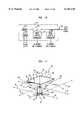
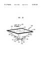
- FIG. 2illustrates a four camera omnidirectional or panoramic viewing system using a four-sided pyramid with reflective surfaces
- FIG. 3illustrates how a reflective surface of the pyramid is used to provide each camera with a common optical center
- FIG. 4illustrates the top view of the pyramid illustrating the camera positions
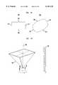
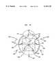
- FIG. 5illustrates an eight-sided pyramid with reflective side surfaces
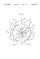
- FIG. 6is a top view of the pyramid of FIG. 5;
- FIG. 7is a block diagram of a system to control data produced by the cameras
- FIG. 8illustrates the association between the data received from the cameras and the view presented to a user
- FIG. 9illustrates an addressing scheme for the memory of FIG. 7
- FIG. 10is a block diagram of the controller of FIG. 7;
- FIG. 11illustrates the viewing system of FIG. 2 with a fifth camera
- FIG. 12illustrates a top view of the pyramid of FIG. 2 with displaced virtual optical centers
- FIG. 13illustrates the pyramid of FIG. 12 with shades positioned in blind regions
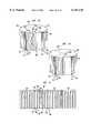
- FIG. 14illustrates a panoramic viewer using pyramids stacked base to base
- FIG. 15illustrates a panoramic viewer using nested pyramids
- FIG. 16illustrates a spherical viewer using nested pyramids
- FIG. 17illustrates a stand used to support a panoramic viewer
- FIG. 18illustrate two types of distortion
- FIG. 19illustrates a calibration process
- FIG. 20illustrates the association between data received from the cameras and the view presented to the user with distortion
- FIG. 21illustrates how distorted image data is stored
- FIG. 22illustrates how mapped image data is stored
- FIG. 23is a block diagram of a panoramic camera system where image mapping is used.
- FIG. 24illustrates a reflective pyramid with two virtual optical centers
- FIG. 25illustrates the pyramid of FIG. 24 viewed from the base
- FIG. 26illustrates a cross section of the pyramid of FIG. 24 taken along line AA;
- FIG. 27illustrates a cross section of the pyramid of FIG. 24 taken along line CC of FIG. 25;
- FIG. 28illustrates the cameras associated with one of the virtual optical centers of the pyramid
- FIG. 29illustrates a reflective pyramid with three virtual optical centers
- FIG. 30illustrates using different pairs of virtual optical centers for different viewing directions
- FIG. 31illustrates a reflective pyramid with eight virtual optical centers
- FIG. 32illustrates using different pairs of virtual optical centers for different viewing directions.
- FIG. 33illustrates a block diagram of a panoramic viewing system with three virtual optical centers.
- FIG. 2illustrates a four camera system for providing a 360 degree view to a user, where the cameras each have a common or nearly common virtual optical center within the pyramid.
- Pyramid 40has reflective sides 42, 44, 46, and 48 and may be a hollow, solid, or truncated structure. In a preferred embodiment, each of the reflective sides forms a 45 degree angle with a plane parallel to base 50 and passing through the vertex of pyramid 40.
- Cameras 52, 54, 56, and 58are associated with pyramid reflective surfaces 48, 42, 44, and 46, respectively.
- the camerasmay be image gathering devices such as an optical scanner. As a result, camera 52 views a reflection from surface 48 to enable it to view objects in the direction of arrow 60.
- Camera 54views a reflection from surface 42 to view objects in the direction of arrow 62.
- Camera 56views a reflection from surface 44 to view objects in the direction of arrow 64
- camera 58views a reflection from surface 46 to view objects in the direction of arrow 66.
- Each camerahas a 90 degree field of view; however, larger fields of view may be used and the overlapping portion of the images may be removed by deleting or combining the pixels associated with the overlapping views.
- the combination of the four cameras viewing reflections from their associated reflective surfaces on pyramid 40produce a 360 degree view of the area surrounding pyramid 40. When the mirrors are at 45 degree with respect to the pyramid base, it is desirable to locate the optical center of each camera on a plane that is parallel to base 50 and intersects vertex 70 of pyramid 40.
- Each camera's optical centershould also be located on a line that passes through vertex 70 and is perpendicular to the base line of the camera's associated reflective surface.
- the optical center of camera 54is located on line 72.
- Line 72is perpendicular to base line 74 of reflective surface 42.
- Line 72is in a plane that passes through vertex 70 and is parallel to base 50.
- the optical center of camera 56is positioned on line 76 which is perpendicular to baseline 78
- the optical center of camera 58is positioned on line 80 which is perpendicular to base line 82
- the optical center of camera 52is positioned on base line 84 which is perpendicular to base line 86.
- Each camera optical centeris positioned on one of the above described lines at a distance X from vertex 70 and each camera has its optical axes or direction of view pointing perpendicular to base 50.
- the distance Xshould be such that the reflective surface reflects as much of the camera's field of view as desired; however, the defects in the reflective surface become more visible when the camera is moved closer to the reflective surface.
- This positioning of optical centersresults in the cameras sharing a virtual optical center located at, or substantially at, position 90.
- Virtual optical center 90is located a distance X from the vertex 70 on a line that passes through vertex 70 and is perpendicular to base 50.
- a pyramid configurationhas been discussed in this example, different planar mirror geometries may be used to redirect fields of view so that the cameras have virtual optical centers that are substantially co-located.
- solid, hollow or partial polyhedronsmay be used.
- the base and vertexdo not have to be physically present and can be thought of as conceptual aids such as a base plane or end and vertex point or end.
- FIG. 3illustrates another view of pyramid 40 where only camera 54 is shown for the sake of simplicity.
- Camera 54is positioned on line 72 so as to have a virtual optical center at, or nearly at, position 90 within pyramid 40. If camera 54 has a 90 degree field of view in the direction perpendicular to base 50, and if the optical center of camera 54 is at a distance of X from vertex 70 along line 72, camera 54 has a 90 degree view in the direction of arrow 62. In similar fashion, cameras 56, 58, and 52 have 90 degree views in the direction of arrows 64, 66, and 60, respectively. This arrangement inexpensively produces a 360 degree field of view of an area because cameras with a 90 degree field of view have relatively inexpensive optics.
- FIG. 4is a top view of pyramid 40.
- FIG. 4illustrates the placement of the optical center of camera 54 along line 72.
- Line 72should be in a plane passing through vertex 70 and is parallel to base 50.
- the lineshould also be perpendicular to base line 74 of pyramid 40.
- the camera's optical centershould be positioned a distance X, or a distance substantially equal to X, from vertex 70 along line 72.
- Point 100is located on base 50 at a position where a line from vertex 70 perpendicularly intersects base 50.
- the optical centers of cameras 56, 58 and 52are positioned the distance X, or a distance substantially equal to X, along lines 76, 80 and 84, respectively.
- FIG. 5illustrates an eight-sided pyramid 120.
- Pyramid 120has reflective surfaces 122 where each of surfaces 122 forms a 45 degree angle with a plane that passes through vertex 130 and is parallel to base 124.
- each reflective surface of FIG. 5may have a camera associated with it.
- Each camera's optical centeris positioned on a line that is in a plane that passes through vertex 130 and is parallel to base 124. The line is perpendicular to base line 132 of the reflective surface associated with the camera to be positioned.
- Using an eight-sided pyramidoffers the advantage of using cameras with only a 45 degree horizontal field of view to obtain a 360 degree view. Cameras with only a 45 degree field of view have inexpensive optics and enable a 360 degree view to be constructed using relatively inexpensive components.
- FIG. 6is a top view of pyramid 120.
- each camera's optical centeris positioned along a line 134 which is in a plane that passes through vertex 130 and is parallel to base 124.
- the optical centersare positioned a distance X, or a distance substantially equal to X, along line 134 which is perpendicular to the appropriate base line 132.
- Point 140is on base 124 at the point of intersection between base 124 and a line that passes through vertex 130 and is perpendicular to base 124.
- Polyhedrons or pyramids having more or less reflective sidesmay be used.
- the advantage of using pyramids having a large number of sidesis that cameras with moderate to small fields of view may be used. Cameras with moderate fields of view have relatively inexpensive optics.
- the number of sides used in a pyramidis somewhat limited by the cost of providing a large number of cameras.
- a 360 degree view of a scenemay be provided using a pyramid having three reflective sides. It may be expensive to use only a three-sided pyramid in order to provide a 360 degree field of view.
- This embodiment of the inventionuses three cameras each with a 120 degree field of view, and cameras with such a wide field of view use relatively expensive optical components.
- the reflective elementmay include at least one non-reflective facet.
- a pyramid configurationhas been discussed in this example, different planar mirror geometries may be used to redirect fields of view so that the cameras have virtual optical centers that are substantially co-located.
- solid, hollow or partial polyhedronsmay be used.
- the base and vertexdo not have to be physically present and can be thought of as conceptual aids such as a base plane or end and vertex point or end.
- FIG. 7illustrates a block diagram of a system for controlling data produced by the cameras of a viewing device such as the viewing device described in FIGS. 2 through 4.
- Cameras 52, 54, 56 and 58obtain a 360 degree view of an area via their associated reflective surfaces of pyramid 40.
- the image signal or output signal of cameras 52, 54, 56 and 58are passed through analog to digital converters (A/D) 160, 162, 164, and 166, respectively.
- A/Danalog to digital converters
- the output of the camerascan be thought of as a stream of pixels and the output of the A/Ds can be thought of as data representative of the pixels from the cameras.
- the output of the A/Dsare passed through mux 170.
- Mux 170allows the pixel data from each of the A/Ds to reach memory 172.
- Controller 174cycles the select lines of mux 170 so that the outputs of all of the A/Ds are stored in memory 172.
- Mux 170is switched at a rate that is four times the pixel rate of the cameras. If more or less cameras are used, the rate at which mux 170 is switched will be increased or slowed accordingly. It is also possible to eliminate mux 170 and to store the output of each A/D in a separate memory.
- Controller 174is implemented using a microprocessor which provides control signals to counters that control the switching of mux 170 and counters used to provide addressing to memory 172. The control signals to the counters include reset, enable and a starting offset.
- memory 172contains a 360 degree view of a scene.
- Pixel information stored in memory 172is passed through digital to analog converter (D/A) 176 and to video display 178.
- D/Adigital to analog converter
- the actual portion of memory 172 that is passed to video display 178 via D/A 176is controlled via user input device 180.
- User input device 180may be a common device such as a mouse, joystick, or keyboard. The user may simply lean a joystick to the right to shift his view to the right, lean the joystick to the left to shift the view to the left, or leave the joystick in the center to keep the view unchanged.
- controller 174Based on the input from user device 180, controller 174 varies offsets and starting addresses that are used to provide addressing to memory 172.
- FIG. 8illustrates the relationship between the data provided by the cameras and the view available to the user. Since the cameras share a virtual optical center, the view can be thought of as a cylindrical view.
- Sector 200can be thought of as representing the information provided by camera 52
- sector 202can be thought of as representing the information provided by camera 54
- sector 204can be thought of as representing the information provided by camera 56
- sector 206can be thought of as representing the information provided by camera 58.
- the surface of the cylinder in each sectorcan be thought of as a collection of columns, where each column is composed of pixels.
- sector 200can be thought of as a collection of columns including columns 210, 212, 214, and 216.
- the output produced by camera 54can be thought of as a collection of columns which include column 218 in sector 202 and the output of camera 58 can include columns such as column 220 in sector 206.
- FIG. 9illustrates how memory 172 is divided to provide easy access to different views based on signals from user input device 180.
- Sections 230, 232, 234, and 236correspond to sectors 206, 200, 202, and 204, respectively.
- Each of sections 230, 232, 234, and 236can be thought of as a block within memory 172.
- the blocks in memory 172are broken into columns of sequential addresses.
- the first column of memory segment 230corresponds to the first column of pixels of sector 206.
- the number of memory positions associated with a columnshould be at least sufficient to have one location for each pixel in a particular column. For example, if a column of pixels from FIG. 8 includes 1000 pixels, each column associated with the memory segments of FIG. 9 should have at least 1000 locations.
- the number of columns associated with a particular memory segmentshould be at least equal to the number of columns associated with a particular section of the cylinder of FIG. 8.
- a camerascans in a horizontal direction, sequential pixels are written in adjacent columns, but possibly different rows, of a particular memory segment by simply changing an offset to a counter generated address.
- the overall write addressis generated by adding the offset to the counter's output. This offset is changed at the rate in which the horizontally scanned pixels are received. After a horizontal scan is completed, the counter is incremented and once again the offsets are changed at the horizontal scan rate.
- the columnsare addressed by changing the offset at the horizontal pixel scan rate, and incrementing the counter at the vertical scan rate. This type of addressing scheme is used for accessing columns within each memory segment.
- a write segment offsetis added to the sum of the counter output and the column offset.
- the write segment offsetpermits addressing memory segments 230, 232, 234, and 236.
- the segment offsetis changed at the same rate as mux 170 is switched.
- Pixel datais read from memory 172 in a similar fashion.
- the sum of a counter output and two sets of offsetsare used to generate a read address.
- the read addressis generated by switching a read column offset at a rate that is equal to the horizontal scan rate of a video display.
- the read counteris incremented and the read column offsets are changed at a rate equal to the horizontal scan rate of the display.
- the offset addressesare changing at the display's horizontal display rate and the counter is incremented at a rate equal to the vertical scan rate of a display. It is possible to read data out at a rate faster or slower than required by the video display; however, if read out faster, a buffer memory should be used, if read out slower the video display may appear choppy to the viewer.
- the cylindrical arrangement of pixels of FIG. 8is typically displayed on a flat or nearly flat display.
- the imagemay be displayed by compensating for converting between a cylindrical surface and a flat surface. This may be carried out using a simple conversion algorithm within a common digital signal processing integrated circuit. Methods for these types of conversions are well known in the art and can be found in "A Guided Tour of Computer Vision, Vishvjit S. Nalwa, Addison-Wesley Publishing Co., Reading, Mass., 1993". It is also possible to carry out the conversion using a very high resolution display.
- columns 240-248are read from memory 170.
- Column 240is the first column in segment 232 and column 248 is the last column in segment 232. If the user decides to move the view in a counter-clockwise direction, the start column will shift to the right so that the read operation begins at column 246 and ends at column 250.
- column 246is the second column associated with memory segment 232 which has the pixel data from camera 52
- column 250is the first column of pixel data associated with camera 56. As the user shifts the view, the starting column shifts in relationship to the user's commands.
- the start column of FIG. 9moves to the right, similarly, if the viewer indicates that the view should shift in a clockwise direction, the start column shifts to the left.
- columnsare addressed by using offsets, if the offsets involve moving between memory segments, a read segment offset is added to the sum of the column offset and counter output.
- FIG. 10illustrates a block diagram of controller 174.
- Controller 174includes microprocessor 270 and memory 272.
- Memory 272includes RAM and ROM.
- Processor 270receives commands on line 274 from user input device 180.
- Microprocessor 270controls start, stop and reset of counter 276.
- Counter 276controls the select lines of mux 170.
- Counter 276counts at a rate that is four times the horizontal scan rate of the cameras.
- Write address generator 278provides write addressing for memory 172.
- Write address generator 278includes a counter, register for storing offsets and adder for adding the offsets and counter output.
- Microprocessor 270controls the offset selection and the counters used by write address generator 278.
- the write addressesare formed as described with regard to FIG. 9.
- Read address generator 280provides read addresses to memory 172.
- Read address generator 280includes a counter, register for storing offsets and adder for adding the offsets and counter output. As with write address generator 278, microprocessor 270 controls the offset selection and the counters of read address generator 280. Microprocessor 270 also controls the starting column used by the counters based on inputs provided on line 274 from user input 180.
- the write and read addressesare provided to memory 172 separately if memory 172 is implemented using a two port memory. If memory 172 is implemented with a single port memory, the write and read addresses are multiplexed to memory 172.
- FIG. 11illustrates the viewing system of FIG. 2 with a fifth camera.
- Camera or image gathering device 400is located in pyramid 40 with the optical center of camera 400 located at, or nearly at, virtual optical center 90.
- Camera 400views objects in the direction of arrow 410.
- the resulting viewcoupled with the views of the remaining four cameras, provides a nearly spherical view.
- the nearly spherical viewing systembecomes a nearly spherical projection system.
- a camera or projection devicemay be placed at the virtual optical center of viewing/projection devices having pyramids with three, four or more sides.
- base edges 420 of the reflective surfacesshould be beveled to avoid undesirable obstruction of camera 400's field of view.
- Device 400should be moved so that device 400's optical center is positioned away from virtual optical center 90 in the direction of arrow 410.
- Device 400's optical centershould be positioned so that the device's used field of view does not include edges 420.
- FIG. 12illustrates a top view of the pyramid of FIG. 2.
- camera 52, 54, 56, and 58have been moved upward in the direction of base 50.
- virtual optical centers 500, 502, 504 and 506, which correspond to cameras 52, 54, 56 and 58, respectively,are moved away from virtual optical center 90.
- Eliminating these portions of the fields of viewalleviates the need to provide image processing that compensates for image artifacts at the edges. It is desirable to keep virtual optical centers 500, 502, 504, and 506 closely clustered so that planes 524, 526, 528, and 530 are only as thin as necessary to avoid edge artifacts. By maintaining such thin planes, the need to process the images at their common boundaries is removed while minimizing the noticeable effect seen by a user.
- FIG. 13illustrates the pyramid of FIG. 12 with shades 560, 562, 564, and 566 positioned in planar regions 524, 526, 528, and 530, respectively.
- the shadesreduce the amount of unwanted light that enters the cameras. Similar shades may be placed in blind regions between device 400 and one or more of the other image processing devices. It is also possible to place a shade on base 50 with the edges of the shade extending beyond the edges of the base to reduce the amount of unwanted light that enters cameras 52, 54, 56, and 58 from sources behind base 50.
- FIG. 14illustrates reflective pyramids 602 and 604 arranged in a base-to-base configuration.
- the basesmay be in contact with each other or spaced apart.
- Reflected pyramids 602 and 604each have four reflective side facets.
- Pyramid 602has reflective side facets 608, 610, 612, and 614.
- Reflective pyramid 604has reflective sides 616, 618, 620, and 622.
- Pyramid 602includes vertex 624 and pyramid 604 includes vertex 626. Vertices 624 and 626 are on a line 628 that is perpendicular to the base of each pyramid.
- Each pyramidhas four image processing devices such as cameras with a field of view being redirected by a reflective surface.
- a camera with an optical center positioned at point 630has a field of view in the direction of arrow 632 where that field of view is redirected by reflective surface 608.
- a second camera with an optical center at point 634has a field of view in the direction of arrow 636 which is redirected by reflective surface 610.
- a third camera with an optical center at point 638has a field of view in the direction of arrow 640 which is redirected by reflective surface 612.
- a fourth camera with an optical center at point 642has a field of view in the direction of arrow 644 which is redirected by reflective surface 614.
- a first camera with an optical center at point 646has a field of view in the direction of arrow 648 which is redirected by reflective surface 616.
- a second camera with an optical center at point 650has a field of view in the direction of arrow 652 which is redirected by surface 618.
- a third camera with an optical center at point 654has a field of view in the direction of arrow 656 which is redirected by reflective surface 620.
- a fourth camera with an optical center at point 658has a field of view in the direction of arrow 660 which is redirected by reflective surface 622.
- the cameras associated with each of the pyramidsare positioned in a way similar to how the cameras were positioned with regard to FIGS.
- each set of four camerasshares a common virtual optical center or have closely clustered virtual optical centers within their associated pyramid.
- Each set of camerasmay also have offset virtual optical centers within their associated pyramid.
- the camerasmay be positioned so that the cameras associated with each pyramid share a common virtual optical center along line 628 where the bases of the two pyramids meet. It is also possible to position the cameras so that their offset virtual optical center are clustered about a point on line 628 where the bases of the two pyramids meet.
- FIG. 14increases the vertical fields of view as compared to the viewers discussed with regard to FIGS. 2, 3, and 4.
- the viewer of FIG. 14increases the vertical field of view by using two cameras rather than one camera for the same or nearly the same horizontal field of view.
- a projectormay be constructed by replacing the cameras with image producing devices.
- reflective pyramids 602 and 604may be rotationally misaligned with respect to each other. This misaligned relationship is obtained by rotating one or both of the pyramids about an axis that passes through the vertices of both pyramids. For example, the axis may be co-linear with line 628. As a result of this rotation, the side edges of the reflective side facets of pyramid 602 will not align with the side edges of the reflective side facets of pyramid 604.
- a pyramid configurationhas been discussed in this example, different planar mirror geometries may be used to redirect fields of view so that the cameras have virtual optical centers that are substantially co-located.
- solid, hollow or partial polyhedronsmay be used.
- the base and vertexdo not have to be physically present and can be thought of as conceptual aids such as a base plane or end and vertex point or end.
- FIG. 15illustrates two reflective pyramids.
- Reflective pyramid 702is nested within reflective pyramid 704. It should be noted that more than two reflective pyramids may be nested. For example, another reflective pyramid may be nested within reflective pyramid 702 and yet another reflective pyramid may be nested within the pyramid that is nested within pyramid 702. Vertex 706 of pyramid 702 and vertex 708 of pyramid 704 are on a line 710 which is perpendicular to the bases of both pyramids.
- each pyramidincludes four image processing devices such as cameras each with a field of view that is redirected by a reflective surface of their associated pyramid.
- Pyramid 702includes reflective side facets 712, 714, 716, and 718.
- Reflective pyramid 704includes reflective side facets 720, 722, 724, and 726.
- Four camerasare positioned so that their field of view is redirected by the reflective surfaces of pyramid 702.
- a first camera with an optical center at point 730 and a field of view in direction of arrow 732has its field of view redirected by reflective surface 712.
- a second camera with an optical center at point 734 and a field of view in the direction of arrow 736has its field of view redirected by reflective surface 714.
- a third camera with an optical center at point 738 and a field of view in the direction of arrow 740has its field of view redirected by reflective surface 716.
- a fourth camera with an optical center at point 742 and a field of view in the direction of arrow 744has its field of view redirected by reflective surface 718.
- pyramid 702 and its associated camerasare positioned so that the field of view of the cameras is not obstructed by pyramid 704. This is accomplished by allowing pyramid 702 to extend beyond the base of pyramid 704.
- a first camera with an optical center at point 750 and a field of view in the direction of arrow 752has its field of view redirected by reflective surface 720.
- a second camera with an optical center at point 754 and a field of view in the direction of arrow 756has its field of view redirected by reflective surface 722.
- a third camera with an optical center at point 758 and a field of view in the direction of arrow 760has its field of view redirected by reflective surface 724.
- a fourth camera with an optical center at point 762 and a field of view in the direction of arrow 764has its field of view redirected by reflective surface 726.
- the cameras associated with each of the pyramidsare positioned in accordance with the positioning illustrated with FIGS. 2, 3, 4, 11, and 12 so that the eight cameras share a virtual optical center at position 770 or have closely clustered virtual optical centers within pyramid 702. Each set of cameras may also have offset virtual optical centers within pyramid 702.
- the panoramic viewer of FIG. 15can be provided with a ninth camera having an optical center at point 770 and a field of view in the direction of arrow 772 to provide a viewer with a partially-spherical view.
- the camera having an optical center at position 770may use a wide-angle lens to provide a broader view.
- FIG. 16illustrates the partially-spherical viewer of FIG. 15 with an additional camera having an optical center at point 780 and a field of view in the direction of arrow 782 where that field of view is redirected by planar mirror 784.
- optical center 780is on line 710 which passes through the vertices of pyramid 702 and 704 as well as virtual optical center 770.
- point 780is placed a distance away from planar mirror 784 that is equal or nearly equal to the distance between planar mirror 784 and virtual optical center 770.
- the cameramay be provided with a wide-angle lens.
- planar mirror 784may be replaced with a curved mirror to provide a wider field of view for the camera positioned at point 780 and minimize the need for a wide-angle lens.
- a pyramid configurationhas been discussed in this example, different planar mirror geometries may be used to redirect fields of view so that the cameras have virtual optical centers that are substantially co-located.
- solid, hollow or partial polyhedronsmay be used.
- the base and vertexdo not have to be physically present and can be thought of as conceptual aids such as a base plane or end and vertex point or end.
- a projectormay be constructed by replacing the cameras with image producing devices.
- reflective pyramids 702 and 704may be rotationally misaligned with respect to each other. This misaligned relationship is obtained by rotating one or both of the pyramids about an axis that passes through the vertices of both pyramids. For example, the axis may be co-linear with line 710. As a result of this rotation, the side edges of the reflective side facets of pyramid 702 will not align with the side edges of the reflective side facets of pyramid 704.
- FIG. 17illustrates a stand used to support a panoramic viewer.
- Reflective pyramid 800is mounted to stand or post 802 using a support member such as hollow tube 804.
- the pyramidis secured to hollow tube 804 at vertex end 806.
- the hollow tubeis secured to stand 802 by angle brackets 808.
- Hollow tube 804extends beyond vertex end 806 so that cameras 810 may be supported by tube 804.
- the camerasare mounted to tube 804 by strap or belt 812 which presses cameras 810 against spacer 814.
- the pressure provided by clamp or strap 812provides friction between camera 810, spacer 814, and the outer surface of tube 804 and thereby mounts cameras 810 to tube 804 in a secure fashion. It is also possible to provide a second strap and associated spacers at end-section 816 of cameras 810.
- Video and power connections to cameras 810are provided by cables 818 which are fed through hollow tube 804 and out through space 820 which is between post 802 and the base of pyramid 800.
- hollow tube 804may be replaced with a solid support member; however, a hollow support member provides a convenient path for routing cables. Feeding the cables through tube 804 prevents the cables from entering the field of view of cameras 810.
- Rubber stands or feet 824are provided at the base end of pyramid 800. These stands may be used in place of post 802 to provide flexibility in application where the user does not want to use post 802.
- the stand of FIG. 17is applicable to the viewer of FIGS. 14, 15, and 16. As discussed with regard to FIG. 17, the viewer is mounted to a hollow tube passing through the vertices or vertex ends of both pyramids.
- a higher quality imagemay be produced by calibrating the camera system.
- Calibrationmay be used to determine image mapping functions (which may be implemented as look up tables) that compensate for different types of image distortion.
- the mapping functionsmay be used to correct barrel distortion which is a distortion introduced by a wide-angle lens.
- Mapping functionsmay also be used to correct other types of distortions such as a rotational distortion resulting from misaligned charged coupled devices within the cameras.
- FIG. 18illustrates a combination of barrel distortion and rotational distortion, where the distortion results in rectangular object 900 appearing as distorted image 902.
- Distorted image 902is rotated with respect to undistorted object 900 and a barrel distortion is seen where edges 904 and 906 of rectangular object 900 appear as edges 908 and 910 of image 902, and where edges 912 and 914 appear as edges 916 and 918, respectively.
- This distortionmay be corrected using mapping functions that are determined by calibrating the camera system.
- FIG. 19illustrates a process for calibrating the camera system.
- a vertical column of equally spaced elliptical dots 930is placed in a fixed position. The dots are white on a black background where the major axis of the elliptical dot is in the vertical direction.
- Panoramic camera 940is then rotated in small discrete steps about an axis 942 passing through the virtual optical center of the panoramic camera.
- the distorted image of the column of elliptical dotsis viewed and a mapping function for that data is determined to remove the distortion. This function maps the image such that the distorted image of each vertical column of equally spaced dots is a vertical column of equally spaced dots in the mapped image.
- mapping functionis computed to apply to every image pixel (including the pixels between the white dots) through interpolation.
- An image mapping functionis determined at each of the discrete steps as the camera is rotated, the union of these mapping functions is combinable into a 2-D to 2-D mapping that ensures not only that each vertical column of equally spaced dots appears as a vertical column of equally spaced dots in the image, but also that these columns are spaced horizontally in proportion to the angular rotation between their image acquisitions, the latter providing a cylindrical (rather than flat) image of the scene.
- FIGS. 20 and 21illustrate how the data representative of the vertical column of elliptical dots is represented as a result of distortion.
- FIG. 20is similar to FIG. 8 in that it illustrates the relationship between the data provided by the cameras and the view available to the user. It should be noted that the vertical column of dots is not in a single column of FIG. 20 as a result of the distortion. The distortion has caused the dots to occupy columns 960, 962, 964 and 966, rather than just a single column.
- FIG. 21is similar to FIG. 9 in that it illustrates how image data is stored. When the distorted image data is stored in memory as represented in FIG.
- the data representative of the dotsalso occupies several columns where columns 980, 982, 984 and 986 correspond to the columns 960, 962, 964 and 966 of FIG. 20, respectively.
- the image mapping function determined during the calibration phaseis used to correct for this distortion when the data is read from the memory represented in FIG. 21.
- the corrected or undistorted image datamay then be displayed to the user or written to a memory used to store data representative of the undistorted image.
- FIG. 22illustrates the relationship between the data read from the memory of FIG. 21 and the undistorted view made available to a user.
- the mapping function associated with column 1000specifies that when reading data for use in the uppermost portion of column 1000, data is read from column 980 and when reading data for use in the portion of column 1000 just below, data is read from column 982.
- the mapping functionalso specifies that when reading data for use in the middle portion of column 1000, data is read from column 984. Moving further down column 1000, data is then read from column 982, then column 980, and eventually from column 986 when data for use at the bottom of column 1000 is retrieved.
- the column of datawill appear vertical to a user viewing a display.
- FIG. 22illustrates that the data retrieved from the memory of FIG. 21 now appears as a vertical column where the distortion is no longer evident.
- a similar mapping function, as determined during calibration,is used for each column of FIG. 22 to produce an undistorted image for display. It should be noted that multiple discrete rotational steps used to calibrate the panoramic camera could be substituted by a group of several columns illustrated in FIG. 22.
- Color and intensity calibrationmay also be carried out using a procedure similar to the procedure illustrated in FIG. 19.
- column 930 of elliptical dotsis replaced by a known color pattern.
- the panoramic camerais then rotated so that each camera captures an image of the color pattern.
- Several color patterns(such as various shades of red, green, blue, and gray) could be used one by one.
- the data from each camerais adjusted to correct any red, green, or blue distortion so that the produced image has a color pattern that closely matches the calibration color pattern.
- the intensity of each pixel from each camerais adjusted so that there is relatively uniform intensity and color within a single camera's image and between the images of the multiple cameras when viewing a scene with constant color and brightness.
- the pixel-by-pixel adjustmentmay be stored in a table.
- a less precise, but simpler method of color and intensity calculationmay be used. This method simply involves manually adjusting the color and intensity controls of each camera to get correct color and intensity when viewing a scene with a particular color and intensity. It should be noted that by using this method, all of the pixels of a particular camera receive the same adjustments.
- FIG. 23illustrates a panoramic camera system where calibration based image mapping correction is used.
- FIG. 23is similar to FIG. 7; however, it should be noted that a frame buffer memory and an additional microprocessor have been included.
- Cameras 52, 54, 56, and 58gather image data and then pass the data to analog-to-digital converters 160, 162, 164, and 166, respectively.
- the output of the analog-to-digital convertersare then passed through red, green, blue, and intensity adjustment units 1010, 1012, 1014, and 1018. It is possible to place these units before the analog/digital converters, if the adjustment units are analog units. Additionally, it is also possible to use cameras that have the adjustment units built into each camera.
- the adjustment unitsare programmed or set to adjust the color and intensity as determined by the calculation procedures.
- Each of these unitsadjust the red, green, and blue levels and the overall levels of the signals from the analog-to-digital converter.
- analog-to-digital converters 160 to 166typically receive three signals and output three signals, where each pair of input and output signals corresponds to one of the colors red, green, and blue.
- Units 1010 through 1016simply adjust the relative amplitudes of the red, green, and blue signals in accordance with the settings determined during the calibration procedure.
- Each of units 1010 through 1018also adjust the overall amplitude of the red, green, and blue signals in accordance with the overall intensity calibration settings.
- the outputs of the red, green, and blue intensity adjustmentsare then passed through a multiplexer as discussed in FIG. 7, and are passed to frame buffer memory 1030. It is also possible to replace frame buffer 1030 with an individual frame buffer for each of red, green, blue and intensity units 1010, 1012, 1014, and 1018. The outputs of each of the individual frame buffer may then be passed to microprocessor 1030 via multiplexer 170.
- Frame buffer memory 1030is operated in a fashion similar to memory 172 of FIG. 7 and stores the data representing the distorted images as was discussed in reference to FIG. 21.
- Microprocessor 1040then reads the data from frame buffer memory 1030 using the mapping functions determined during the calibration procedure and then writes the data into display memory 1050. Recalling the discussion associated with FIG. 22, the data representing undistorted images is then stored in memory 1050 for retrieval by the users.
- the userscan retrieve the data as is discussed in reference to FIG. 7 where the data read out is determined based on a user's input. It is also possible for the entire contents of display memory to be made available to each user.
- the datamay be communicated to each user through a communication network such as a telephone network or a data network, or it may be directly communicated to the user via a dedicated wired or wireless communication path.
- the userthen may use a digital-to-analog converter to convert the data into an analog format that may be displayed for the user or the user may use the digital data directly and forego the use of a digital-to-analog converter.
- FIG. 24illustrates reflective pyramid 1200 with reflective surfaces 1202, 1204, 1206 and 1208.
- Line 1210is the axis of the pyramid which passes through vertex 1212 of pyramid 1200 and is perpendicular to base 1213 of the pyramid.
- Pyramid 1200is similar to the pyramid discussed with regard to FIGS. 2 and 3. In this case, however, rather than a single virtual optical center, two virtual optical centers are provided.
- Virtual optical centers 1214 and 1216are used to provide a stereo panoramic viewer. In order to closely mimic normal human vision, it is desirable that virtual optical centers 1214 and 1216 be spaced apart horizontally a distance that is approximately equal to the typical distance between a person's eyes.
- Each virtual optical center 1214 and 1216is associated with a set of cameras where each camera in the set has its field of view redirected by a reflective surface of the pyramid so that portions of the redirected fields of view are substantially contiguous.
- the camerasare arranged and supported as discussed with regard to FIGS. 2, 3 and 17, however, the cameras are arranged so that each set of cameras has a virtual optical center that is displaced from the center of the pyramid.
- the cameras for each optical centerare arranged similar to the way that cameras were arranged in regard to FIGS. 2 and 3, however, the cameras are arranged so that each of the two sets of cameras has a different virtual optical center, where one set of cameras has a virtual optical center at point 1214 and the other set of centers has a virtual optical center at position 1216.
- FIG. 25illustrates pyramid 1200 when viewed at the base along axis 1210 and in the direction of arrow 1218 of FIG. 24. It should be noted that virtual optical centers 1214 and 1216 are displaced horizontally from the center axis 1210 with the distance between them approximately equal to the typical distance between a pair of human eyes. In this example, virtual optical centers 1214 and 1216 appear on a line AA that passes through axis 1210.
- FIG. 26illustrates a cross section of pyramid 1200 taken along line AA of FIGS. 24 and 25.
- Point 1230represents the optical center of a camera that has its field of view redirected by reflective surface 1202 of pyramid 1200.
- Optical center 1230is positioned so that its perpendicular distance 1232 from reflective surface 1202 is equal to perpendicular distance 1234 which is the perpendicular distance between virtual optical center 1214 and reflective surface 1202.
- point 1238represents the optical center of a camera that has its field of view redirected by reflective surface 1204.
- Optical center 1238is positioned so that its perpendicular distance 1240 from reflective surface 1204 is equal to perpendicular distance 1242 between virtual optical center 1214 and reflective surface 1204.
- FIG. 27illustrates a cross section of pyramid 1200 cut along line CC of FIG. 25.
- Point 1250represents the optical center of a camera whose field of view is redirected by reflective surface 1208.
- Point 1252represents the optical center of a camera whose field of view is redirected by reflective surface 1206.
- Point 1250is positioned so that its perpendicular distance 1254 from reflective surface 1208 is equal to perpendicular distance 1256 between reflective surface 1208 and virtual optical center 1214.
- Optical center 1252is positioned so that its perpendicular distance 1258 from reflective surface 1206 is equal to perpendicular distance 1260 between virtual optical center 1214 and reflective surface 1206.
- FIG. 28illustrates the cameras associated with virtual optical center 1214 and are positioned so that the optical center of each camera is arranged in accordance with FIGS. 26 and 27.
- a camera with an optical center at position 1230has a field of view in direction of arrow 1260 and the field of view is redirected by reflective surface 1202 so that the virtual optical center for the camera associated with point 1230 is at virtual optical center 1214.
- a camera with an optical center at position 1250has a field of view in the direction of arrow 1262 where the field of view is redirected by surface 1208. This results in the camera associated with point 1250 having a virtual optical center at point 1214.
- a camera with an optical center at point 1252has a field of view in the direction of arrow 1264 where that field of view is redirected by surface 1206. This results in the camera associated with point 1252 having a virtual optical center at point 1214.
- a similar set of camerasmay be positioned as was discussed with regard to FIGS. 26 and 27 so that a second virtual optical center may be created at point 1216. The additional cameras associated with virtual optical center 1216 have not been shown for the sake of simplicity.
- a complete panoramic imageis produced for each of the virtual optical centers 1214 and 1216.
- the images associated with each of the virtual optical centersare processed as described with regard to FIGS. 7 and 23.
- two imagesare delivered; preferably one designated left and one designated right where the left image is provided to the left eye of the user and the right image is provided to the right eye of the user.
- Thisprovides a stereo view that is equivalent to the user viewing the world from inside the pyramid with one eye located at virtual optical center 1214 and the other eye located at virtual optical center 1216.
- the virtual optical center associated with each of the camerasneed not be exactly at a single location or point such as virtual optical center 1214.
- the optical centersmay be closely clustered around point 1214 simply due to difficulties with precisely aligning the cameras. Additionally it may be desirable to intentionally cluster the virtual optical centers associated with the cameras around point 1214 so that a set of offset virtual optical centers are produced which will result in blind regions as described with regard to FIG. 12. These blind regions may be used to remove the portions of the images that may be distorted due to the edges of the pyramids where the different reflective surface of the pyramid meet.
- FIG. 29illustrates reflective pyramid 1300.
- Reflective pyramid 1300has axis 1302 which passes through the vertex of the pyramid and is perpendicular to the base of the pyramid.
- the pyramidis part of a panoramic viewer which has three virtual optical centers 1304, 1306 and 1308.
- Each of the virtual optical centershas a set of cameras that are positioned in accordance with the discussion of FIGS. 26 and 27.
- the virtual optical centersare an equal distance 1310 from axis 1302 and are arranged so that they are each a distance 1312 from each other, where the distance 1312 is approximately equal to the typical distance between a person's eyes. This arrangement results in each virtual optical center having associated with it a panoramic view.
- FIG. 30is also a view of pyramid 1300 looking downward at the base from outside the pyramid.
- FIG. 30illustrates which pair of virtual optical centers are used to provide images to a user. The pair of virtual optical centers used depends on which direction the user desires to view.
- lines 1320, 1322 and 1324are shown.
- Line 1320passes through virtual optical center 1304 and axis 1302.
- Line 1322passes through virtual optical center 1308 and axis 1302 and similarly line 1324 passes through virtual optical center 1306 and axis 1302.
- arrow 1326 of line 1322can be thought of as the center of the view presented by virtual optical centers 1306 and 1304 in the direction of arrow 1326.
- arrow 1328 of line 1324can be thought of as the center of the view provided by virtual optical centers 1308 and 1304 in the direction of arrow 1328.
- Arrow 1330 of line 1320can be thought of as the center of the view provided by virtual optical centers 1306 and 1308 in the direction of arrow 1330.
- Arrow 1332 of line 1322can be thought of as the center of the view provided by virtual optical centers 1306 and 1304 in the direction of arrow 1332.
- Arrow 1334 of line 1324can be thought of as the center of the view provided by virtual optical centers 1304 and 1308 in the direction of arrow 1334.
- Arrow 1336 of line 1320can be thought of as the center of the view provided by virtual optical centers 1306 and 1308 in the direction of arrow 1336.
- left and right imagesare provided to the user from virtual optical centers 1304 and 1306, respectively.
- left and right imagesare provided to the user from virtual optical centers 1304 and 1308, respectively.
- imagesare provided to the left and right eyes from virtual optical centers 1306 and 1308, respectively.
- FIG. 31illustrates reflective pyramid 1400 looking at the base from outside the pyramid with axis 1402 passing through the vertex of the pyramid and perpendicular to the base of the pyramid.
- Pyramid 1400has eight sets of cameras associated with eight virtual optical centers 1404, 1406, 1408, 1410, 1412, 1414, 1416 and 1418.
- the virtual optical centersare equal distance 1420 from axis 1402.
- Each pair of opposite virtual optical centerssuch as optical centers 1404 and 1412 are a distance two times the distance 1420.
- the distance two times distance 1420should be approximately equal to the typical distance between a pair of human eyes.
- FIG. 32illustrates the panoramic viewer of FIG. 31 with reference lines used to illustrate which pair of virtual optical centers are used to provide images based on which direction a viewer desires to see.
- Reference line 1430is drawn through virtual optical center 1406, axis 1402, and virtual optical center 1414.
- Reference line 1432is drawn through virtual optical center 1408, axis 1402, and virtual optical center 1416.
- Reference line 1434is drawn through virtual optical center 1410, axis 1402, and virtual optical center 1418.
- Reference line 1436is drawn through virtual optical center 1412, axis 1402, and virtual optical center 1404.
- the set of virtual optical centers associated with that reference line and that viewing directionis used to provide the left and right images to the user.
- the vieweruses the image from virtual optical center 1410 for a left eye image and the image from virtual optical center 1418 as a right eye image.
- the left and right imagesare provided by virtual optical centers 1412 and 1404, respectively.
- the left and right imagesare provided by virtual optical centers 1414 and 1406, respectively.
- the left and right imagesare provided by virtual optical centers 1416 and 1408, respectively.
- the left and right imagesare provided by virtual optical centers 1418 and 1410, respectively.
- the left and right imagesare provided by virtual optical centers 1404 and 1412, respectively.
- the left and right imagesare provided by virtual optical centers 1406 and 1414, respectively.
- the left and right imagesare provided by virtual optical centers 1408 and 1416, respectively.
- a pyramid configurationhas been discussed in this example, different planar mirror geometries may be used to redirect fields of view so that the cameras have virtual optical centers that are substantially co-located.
- solid, hollow or partial polyhedronsmay be used.
- the base and vertexdo not have to be physically present and can be thought of as conceptual aids such as a base plane or end and vertex point or end.
- FIG. 33illustrates a block diagram of a stereo panoramic viewing system having three virtual optical centers.
- the block diagramis similar to FIG. 23 in that the functions provided to each set of cameras is similar to that shown in FIG. 23.
- camera sets 1500, 1502, and 1504correspond to virtual optical centers 1304, 1306, and 1308 of FIG. 29, respectively.
- each camera setincludes four cameras.
- the output of each camera setis received by red/green/blue correction circuitry 1506.
- Red/green/blue correction circuitry 1506operates similar to the circuitry described with regard to FIG. 23.
- the output of red/green/blue correction circuitry 1506is stored by frame memory units 1508.
- the data representing the images captured by the camerasis written into the frame memories using addresses provided by controller 1510.
- Controller 1510provides addressing to the frame memories as discussed with regard to FIG. 23 and FIGS. 7-9.
- Controller 1510may be implemented using specialized hardware such as an ASIC (Application Specific Integrated Circuit), a microcomputer or microprocessor.
- Datais read from frame memories 1508 and put in display memories 1512 under control of microprocessors 1514.
- the microprocessorsuse image mapping to correct for distortions that were introduced by the camera system. This image mapping process is similar to the process that was described with regard to FIGS. 20-22.
- the output from display memories 1512is again addressed by controller 1510 in the manner similar to that which was discussed with regard to FIGS. 7-9. These outputs may be provided based on a user input that specifies a direction to be viewed.
- the output of display memories 1512is provided to a switch, which in this embodiment is implemented as left multiplexor 1516 and right multiplexor 1518. Each multiplexor is used to select image data from a camera set associated with one of the virtual optical centers.
- the switchmay be implemented using, for example, a mechanical switch, a bus with the selected memory enabled onto the bus, or a microcomputer or microprocessor that accesses the selected memory.
- the selection of image data associated with a particular virtual optical centeris under control of controller 1510 based on a view selected by a user through a user input.
- the actual image data provided in response to user inputis provided as discussed with regard to FIG. 30. It is also possible to provide the entire display memory output for each virtual optical center for viewing and possible editing by a user.
- Left and right image data provided by multiplexors 1516 and 1518can then be provided to a modem 1520 for transfer over communication network 1522. It is also possible to eliminate modem 1520 if communication network 1522 accepts digital data directly. The data from communication network 1522 is received by modem 1524 which then provides data to left and right displays 1526 and 1528. If displays 1526 and 1528 require analog data, digital to analog converters may be placed between modem 1524 and a display.
- User input device 1530if used, may be a device such as a joy stick which provides user selection data to controller 1510 through modem 1524, communication network 1522 and modem 1520.
- the data from multiplexors 1516 and 1518may be passed directly to left display 1532 and right display 1534. If the displays require analog data, digital to analog converters 1536 and 1538 may be used to provide data to left display 1532 and right 1534, respectively. Additionally, user input device 1540 may be used to provide user selection data to controller 1510.
- FIG. 34it should be noted that the number of cameras in camera sets 1500, 1502 and 1504 may vary. For instance, if only three sides of a four-sided pyramid are used for viewing, only three cameras need be included in the camera sets.
- controller 1510 and microprocessors 1514may be combined into a single microprocessor, microcomputer, or computer with sufficient processing speed to provide the addressing needs for the discussed functions.
- the frame memories and the display memoriesmay be combined into a single memory that is addressed so that the data associated with each of the memories of FIG. 33 may be accessed.
Landscapes
- Physics & Mathematics (AREA)
- General Physics & Mathematics (AREA)
- Engineering & Computer Science (AREA)
- Multimedia (AREA)
- Signal Processing (AREA)
- Optics & Photonics (AREA)
- Stereoscopic And Panoramic Photography (AREA)
- Studio Devices (AREA)
- Testing, Inspecting, Measuring Of Stereoscopic Televisions And Televisions (AREA)
- Devices For Indicating Variable Information By Combining Individual Elements (AREA)
- Illuminated Signs And Luminous Advertising (AREA)
- Transforming Electric Information Into Light Information (AREA)
Abstract
Description
Claims (28)
Priority Applications (8)
| Application Number | Priority Date | Filing Date | Title |
|---|---|---|---|
| US09/141,867US6141145A (en) | 1998-08-28 | 1998-08-28 | Stereo panoramic viewing system |
| TW088111816ATW396292B (en) | 1998-08-28 | 1999-07-13 | Stereo panoramic viewing system |
| CA002277712ACA2277712C (en) | 1998-08-28 | 1999-07-19 | Stereo panoramic viewing system |
| EP99306447AEP0989436A3 (en) | 1998-08-28 | 1999-08-17 | Stereoscopic panoramic viewing system |
| CN99118076ACN1247994A (en) | 1998-08-28 | 1999-08-25 | Stereoscopic full views watching system |
| JP24068099AJP3862895B2 (en) | 1998-08-28 | 1999-08-27 | Panorama imager |
| KR1019990035856AKR20000017592A (en) | 1998-08-28 | 1999-08-27 | Stereo panoramic viewing system |
| JP2004183493AJP2005006341A (en) | 1998-08-28 | 2004-06-22 | Panorama picture formation device |
Applications Claiming Priority (1)
| Application Number | Priority Date | Filing Date | Title |
|---|---|---|---|
| US09/141,867US6141145A (en) | 1998-08-28 | 1998-08-28 | Stereo panoramic viewing system |
Publications (1)
| Publication Number | Publication Date |
|---|---|
| US6141145Atrue US6141145A (en) | 2000-10-31 |
Family
ID=22497611
Family Applications (1)
| Application Number | Title | Priority Date | Filing Date |
|---|---|---|---|
| US09/141,867Expired - LifetimeUS6141145A (en) | 1998-08-28 | 1998-08-28 | Stereo panoramic viewing system |
Country Status (7)
| Country | Link |
|---|---|
| US (1) | US6141145A (en) |
| EP (1) | EP0989436A3 (en) |
| JP (2) | JP3862895B2 (en) |
| KR (1) | KR20000017592A (en) |
| CN (1) | CN1247994A (en) |
| CA (1) | CA2277712C (en) |
| TW (1) | TW396292B (en) |
Cited By (73)
| Publication number | Priority date | Publication date | Assignee | Title |
|---|---|---|---|---|
| US6386719B1 (en) | 2001-03-14 | 2002-05-14 | Enroute, Inc. | Precision mounting of front surface mirrors |
| US20020122113A1 (en)* | 1999-08-09 | 2002-09-05 | Foote Jonathan T. | Method and system for compensating for parallax in multiple camera systems |
| US20020196327A1 (en)* | 2001-06-14 | 2002-12-26 | Yong Rui | Automated video production system and method using expert video production rules for online publishing of lectures |
| US6560413B1 (en) | 2001-03-14 | 2003-05-06 | Enroute, Inc. | High-precision panoramic imaging system |
| US6628897B2 (en)* | 2001-06-20 | 2003-09-30 | Sony Corporation | Camera system |
| US20030231244A1 (en)* | 2002-04-22 | 2003-12-18 | Bonilla Victor G. | Method and system for manipulating a field of view of a video image from a remote vehicle |
| US20030233449A1 (en)* | 2002-04-22 | 2003-12-18 | Bonilla Victor G. | Method and system for a computer controlled racing network |
| US20030234866A1 (en)* | 2002-06-21 | 2003-12-25 | Ross Cutler | System and method for camera color calibration and image stitching |
| US20040001137A1 (en)* | 2002-06-27 | 2004-01-01 | Ross Cutler | Integrated design for omni-directional camera and microphone array |
| US20040005927A1 (en)* | 2002-04-22 | 2004-01-08 | Bonilla Victor G. | Facility for remote computer controlled racing |
| US20040077284A1 (en)* | 2002-01-31 | 2004-04-22 | Bonilla Victor G. | Apparatus system and method for adapting a scaled vehicle remote controller for use with an enhanced controller |
| US20040077285A1 (en)* | 2002-04-22 | 2004-04-22 | Bonilla Victor G. | Method, apparatus, and system for simulating visual depth in a concatenated image of a remote field of action |
| US6795109B2 (en) | 1999-09-16 | 2004-09-21 | Yissum Research Development Company Of The Hebrew University Of Jerusalem | Stereo panoramic camera arrangements for recording panoramic images useful in a stereo panoramic image pair |
| US20040223051A1 (en)* | 1999-09-16 | 2004-11-11 | Shmuel Peleg | System and method for capturing and viewing stereoscopic panoramic images |
| US20040263611A1 (en)* | 2003-06-26 | 2004-12-30 | Ross Cutler | Omni-directional camera design for video conferencing |
| US20040263636A1 (en)* | 2003-06-26 | 2004-12-30 | Microsoft Corporation | System and method for distributed meetings |
| US20040263646A1 (en)* | 2003-06-24 | 2004-12-30 | Microsoft Corporation | Whiteboard view camera |
| US20040267521A1 (en)* | 2003-06-25 | 2004-12-30 | Ross Cutler | System and method for audio/video speaker detection |
| US20050018687A1 (en)* | 2003-06-16 | 2005-01-27 | Microsoft Corporation | System and process for discovery of network-connected devices at remote sites using audio-based discovery techniques |
| US20050046703A1 (en)* | 2002-06-21 | 2005-03-03 | Cutler Ross G. | Color calibration in photographic devices |
| US20050117034A1 (en)* | 2002-06-21 | 2005-06-02 | Microsoft Corp. | Temperature compensation in multi-camera photographic devices |
| US20050117015A1 (en)* | 2003-06-26 | 2005-06-02 | Microsoft Corp. | Foveated panoramic camera system |
| US20050180656A1 (en)* | 2002-06-28 | 2005-08-18 | Microsoft Corporation | System and method for head size equalization in 360 degree panoramic images |
| US20050190768A1 (en)* | 2003-06-16 | 2005-09-01 | Ross Cutler | System and process for discovery of network-connected devices |
| US20050206659A1 (en)* | 2002-06-28 | 2005-09-22 | Microsoft Corporation | User interface for a system and method for head size equalization in 360 degree panoramic images |
| US6954695B2 (en) | 2002-01-31 | 2005-10-11 | Racing Visions, Llc | Apparatus system and method for remotely controlling a vehicle over a network |
| US20050243168A1 (en)* | 2004-04-30 | 2005-11-03 | Microsoft Corporation | System and process for adding high frame-rate current speaker data to a low frame-rate video using audio watermarking techniques |
| US20050243166A1 (en)* | 2004-04-30 | 2005-11-03 | Microsoft Corporation | System and process for adding high frame-rate current speaker data to a low frame-rate video |
| US20050243167A1 (en)* | 2004-04-30 | 2005-11-03 | Microsoft Corporation | System and process for adding high frame-rate current speaker data to a low frame-rate video using delta frames |
| US20050280700A1 (en)* | 2001-06-14 | 2005-12-22 | Microsoft Corporation | Automated online broadcasting system and method using an omni-directional camera system for viewing meetings over a computer network |
| US20050285943A1 (en)* | 2002-06-21 | 2005-12-29 | Cutler Ross G | Automatic face extraction for use in recorded meetings timelines |
| US20060023106A1 (en)* | 2004-07-28 | 2006-02-02 | Microsoft Corporation | Multi-view integrated camera system |
| US20060023074A1 (en)* | 2004-07-28 | 2006-02-02 | Microsoft Corporation | Omni-directional camera with calibration and up look angle improvements |
| US20060103723A1 (en)* | 2004-11-18 | 2006-05-18 | Advanced Fuel Research, Inc. | Panoramic stereoscopic video system |
| US20060146177A1 (en)* | 2004-12-30 | 2006-07-06 | Microsoft Corp. | Camera lens shuttering mechanism |
| US20060164552A1 (en)* | 2005-01-21 | 2006-07-27 | Microsoft Corp. | Embedding a panoramic image in a video stream |
| US20060291478A1 (en)* | 2005-06-24 | 2006-12-28 | Microsoft Corporation | Audio/video synchronization using audio hashing |
| US20070014347A1 (en)* | 2005-04-07 | 2007-01-18 | Prechtl Eric F | Stereoscopic wide field of view imaging system |
| US20070058879A1 (en)* | 2005-09-15 | 2007-03-15 | Microsoft Corporation | Automatic detection of panoramic camera position and orientation table parameters |
| US7260257B2 (en) | 2002-06-19 | 2007-08-21 | Microsoft Corp. | System and method for whiteboard and audio capture |
| US20070299912A1 (en)* | 2006-06-26 | 2007-12-27 | Microsoft Corporation, Corporation In The State Of Washington | Panoramic video in a live meeting client |
| US20070300165A1 (en)* | 2006-06-26 | 2007-12-27 | Microsoft Corporation, Corporation In The State Of Washington | User interface for sub-conferencing |
| US20070299710A1 (en)* | 2006-06-26 | 2007-12-27 | Microsoft Corporation | Full collaboration breakout rooms for conferencing |
| US20080008458A1 (en)* | 2006-06-26 | 2008-01-10 | Microsoft Corporation | Interactive Recording and Playback for Network Conferencing |
| US20080298674A1 (en)* | 2007-05-29 | 2008-12-04 | Image Masters Inc. | Stereoscopic Panoramic imaging system |
| US7463280B2 (en) | 2003-06-03 | 2008-12-09 | Steuart Iii Leonard P | Digital 3D/360 degree camera system |
| US7782357B2 (en) | 2002-06-21 | 2010-08-24 | Microsoft Corporation | Minimizing dead zones in panoramic images |
| CN102486274A (en)* | 2010-12-06 | 2012-06-06 | 中强光电股份有限公司 | Light source module and stage lamp |
| CN102595169A (en)* | 2010-12-17 | 2012-07-18 | 微软公司 | Chassis assembly for 360-degree stereoscopic video capture |
| US20130250040A1 (en)* | 2012-03-23 | 2013-09-26 | Broadcom Corporation | Capturing and Displaying Stereoscopic Panoramic Images |
| US20140362176A1 (en)* | 2013-01-05 | 2014-12-11 | Patrick A. St. Clair | Spherical panoramic imaging system |
| US9185391B1 (en) | 2014-06-17 | 2015-11-10 | Actality, Inc. | Adjustable parallax distance, wide field of view, stereoscopic imaging system |
| US20150338674A1 (en)* | 2014-05-24 | 2015-11-26 | Alan Bruce Cornford | Collapsible quasi 3d stereoscopic display and cover |
| US9294672B2 (en) | 2014-06-20 | 2016-03-22 | Qualcomm Incorporated | Multi-camera system using folded optics free from parallax and tilt artifacts |
| US9374516B2 (en) | 2014-04-04 | 2016-06-21 | Qualcomm Incorporated | Auto-focus in low-profile folded optics multi-camera system |
| US9386222B2 (en) | 2014-06-20 | 2016-07-05 | Qualcomm Incorporated | Multi-camera system using folded optics free from parallax artifacts |
| US9383550B2 (en) | 2014-04-04 | 2016-07-05 | Qualcomm Incorporated | Auto-focus in low-profile folded optics multi-camera system |
| US9390752B1 (en)* | 2011-09-06 | 2016-07-12 | Avid Technology, Inc. | Multi-channel video editing |
| US9398264B2 (en) | 2012-10-19 | 2016-07-19 | Qualcomm Incorporated | Multi-camera system using folded optics |
| US9438889B2 (en) | 2011-09-21 | 2016-09-06 | Qualcomm Incorporated | System and method for improving methods of manufacturing stereoscopic image sensors |
| US9485495B2 (en) | 2010-08-09 | 2016-11-01 | Qualcomm Incorporated | Autofocus for stereo images |
| US9541740B2 (en) | 2014-06-20 | 2017-01-10 | Qualcomm Incorporated | Folded optic array camera using refractive prisms |
| US9549107B2 (en) | 2014-06-20 | 2017-01-17 | Qualcomm Incorporated | Autofocus for folded optic array cameras |
| US9819863B2 (en) | 2014-06-20 | 2017-11-14 | Qualcomm Incorporated | Wide field of view array camera for hemispheric and spherical imaging |
| US9832381B2 (en) | 2014-10-31 | 2017-11-28 | Qualcomm Incorporated | Optical image stabilization for thin cameras |
| US9967446B2 (en) | 2015-09-09 | 2018-05-08 | Itx-M2M Co., Ltd. | Personalized shopping mall system using virtual camera |
| US10013764B2 (en) | 2014-06-19 | 2018-07-03 | Qualcomm Incorporated | Local adaptive histogram equalization |
| US10057542B2 (en) | 2014-08-15 | 2018-08-21 | Thereo LLC | System for immersive telepresence |
| US20180288397A1 (en)* | 2017-03-31 | 2018-10-04 | Eys3D Microelectronics, Co. | Image device capable of processing images with depth information |
| US10178373B2 (en) | 2013-08-16 | 2019-01-08 | Qualcomm Incorporated | Stereo yaw correction using autofocus feedback |
| USD858614S1 (en)* | 2016-06-27 | 2019-09-03 | Virtual Marketing Incorporated | Mobile hologram apparatus |
| US10708471B2 (en) | 2013-04-16 | 2020-07-07 | Fraunhofer-Gesellschaft Zur Foerderung Der Angewandten Forschung E.V. | Alignment of a camera system, camera system and alignment aid |
| US10951859B2 (en) | 2018-05-30 | 2021-03-16 | Microsoft Technology Licensing, Llc | Videoconferencing device and method |
Families Citing this family (24)
| Publication number | Priority date | Publication date | Assignee | Title |
|---|---|---|---|---|
| JP2004512701A (en)* | 2000-04-19 | 2004-04-22 | イッサム リサーチ ディベロップメント カンパニー オブ ザ ヘブリュー ユニバーシティ オブ エルサレム | System and method for capturing and displaying a stereoscopic panoramic image |
| KR100343836B1 (en)* | 2000-06-27 | 2002-07-20 | 이성환 | Panorama video surveillance system and controlling method therefore |
| AU2001272647A1 (en)* | 2000-07-21 | 2002-02-05 | Lee Scott Friend | Stereoscopic omnidirectional imaging devices |
| JP2006033570A (en)* | 2004-07-20 | 2006-02-02 | Olympus Corp | Image generating device |
| GB2425363A (en) | 2005-04-18 | 2006-10-25 | Sharp Kk | Panoramic adapter with mirrors formed by rotating conic section |
| KR100765209B1 (en)* | 2006-03-23 | 2007-10-09 | 삼성전자주식회사 | Omnidirectional stereo camera and its control method |
| JP4562683B2 (en)* | 2006-04-19 | 2010-10-13 | 株式会社藤商事 | Game machine |
| MY155821A (en)* | 2007-11-23 | 2015-12-07 | Mimos Berhad | Single camera stereo imaging system |
| JP5099554B2 (en)* | 2008-07-31 | 2012-12-19 | 独立行政法人情報通信研究機構 | 3D display |
| CN101852980B (en)* | 2010-06-09 | 2011-10-05 | 长春理工大学 | A Method of Interactively Playing Panoramic Video Stream on CAVE Projection System |
| FR2964757B1 (en)* | 2010-09-09 | 2013-04-05 | Giroptic | OPTICAL DEVICE FOR CAPTURING IMAGES ACCORDING TO A 360 ° FIELD |
| CN101980080B (en)* | 2010-09-19 | 2012-05-23 | 华为终端有限公司 | Homocentric camera, image processing method and device |
| JP6003199B2 (en)* | 2012-05-08 | 2016-10-05 | ソニー株式会社 | Interchangeable lens camera system and lens data acquisition program |
| JP2014081510A (en) | 2012-10-17 | 2014-05-08 | Sony Corp | Display apparatus |
| EP2835973B1 (en) | 2013-08-06 | 2015-10-07 | Sick Ag | 3D camera and method for capturing of three-dimensional image data |
| TWI510811B (en)* | 2013-09-13 | 2015-12-01 | Quanta Comp Inc | Head mounted system |
| US9262801B2 (en) | 2014-04-01 | 2016-02-16 | Gopro, Inc. | Image taping in a multi-camera array |
| CN104317059B (en)* | 2014-11-14 | 2016-08-24 | 山东理工大学 | Display method of phantom stereoscopic real-time display system |
| TWI574047B (en)* | 2015-06-16 | 2017-03-11 | 緯創資通股份有限公司 | Three-dimensional image display apparatus, methods and systems |
| KR102191050B1 (en)* | 2015-09-09 | 2020-12-14 | 주식회사 아이티엑스에이아이 | Personalized shopping mall system using virtual camera |
| CN106060523B (en)* | 2016-06-29 | 2019-06-04 | 北京奇虎科技有限公司 | Panoramic stereoscopic image acquisition and display method and corresponding device |
| CN106842801A (en)* | 2016-08-31 | 2017-06-13 | 李文松 | A kind of VR phtographic lenses method for designing |
| TWI642973B (en)* | 2017-09-12 | 2018-12-01 | 晶將數位多媒體科技股份有限公司 | 3D floating stereoscopic image creation and display device |
| CN118587992B (en)* | 2024-05-21 | 2025-03-18 | 深圳华竣数创科技有限公司 | A stereoscopic projection display device for a hall |
Citations (47)
| Publication number | Priority date | Publication date | Assignee | Title |
|---|---|---|---|---|
| US2267813A (en)* | 1938-11-05 | 1941-12-30 | Gen Electric | Multicathode ray electrode assembly |
| US2304434A (en)* | 1928-09-03 | 1942-12-08 | Ibm | Projecting device |
| FR1206316A (en)* | 1957-07-19 | 1960-02-09 | Method and devices for panoramic shots, in particular for cinematographic cameras | |
| US3144806A (en)* | 1962-09-28 | 1964-08-18 | Rowe E Carney Jr | Projection system |
| US3286590A (en)* | 1963-02-21 | 1966-11-22 | Conductron Corp | Full circumferential viewing system |
| FR1528819A (en)* | 1967-04-27 | 1968-06-14 | Precitronic | Omni-directional light signal receiver |
| US3420605A (en)* | 1965-06-14 | 1969-01-07 | Vernon L Kipping | Wide field photography and projection |
| US3506344A (en)* | 1968-07-08 | 1970-04-14 | Joseph T Petit Jr | Optical projection system |
| US3740469A (en)* | 1972-04-19 | 1973-06-19 | Us Navy | Reflective panoramic t.v. projection system |
| US3998532A (en)* | 1974-04-08 | 1976-12-21 | The United States Of America As Represented By The Secretary Of The Navy | Wide angle single channel projection apparatus |
| US4078860A (en)* | 1976-10-27 | 1978-03-14 | Globus Ronald P | Cycloramic image projection system |
| US4355328A (en)* | 1981-02-23 | 1982-10-19 | The United States Of America As Represented By The Secretary Of The Navy | 360 Degree closed circuit television system |
| US4357081A (en)* | 1979-02-02 | 1982-11-02 | Nederlandse Centrale Organisatie Voor Toegepast-Natuurwetenschappelijk Onderzoek | Projector for the projection of a panoramic image and camera for the manufacture of films for a projector of this kind |
| US4429957A (en)* | 1981-07-30 | 1984-02-07 | King-Bell Optics, Inc. | Panoramic zoom lens assembly |
| JPS6020692A (en)* | 1983-07-15 | 1985-02-01 | Hitachi Ltd | Device for wide field of vision |
| US4589030A (en)* | 1983-07-25 | 1986-05-13 | Kley Victor B | Solid state camera |
| US4859046A (en)* | 1988-05-20 | 1989-08-22 | Traynor Rodney P | Lane viewer mirror apparatus for vehicles |
| US4890314A (en)* | 1988-08-26 | 1989-12-26 | Bell Communications Research, Inc. | Teleconference facility with high resolution video display |
| US4982092A (en)* | 1973-07-05 | 1991-01-01 | The United States Of America As Represented By The Secretary Of The Navy | 360 Degree optical surveillance system |
| US4985762A (en)* | 1988-12-14 | 1991-01-15 | Horisonscan Inc. | Panoramic interactive system |
| US5016109A (en)* | 1990-07-02 | 1991-05-14 | Bell South Corporation | Apparatus and method for segmenting a field of view into contiguous, non-overlapping, vertical and horizontal sub-fields |
| US5023725A (en)* | 1989-10-23 | 1991-06-11 | Mccutchen David | Method and apparatus for dodecahedral imaging system |
| US5030823A (en)* | 1988-11-28 | 1991-07-09 | Heuft-Qualiplus B.V. | Device for inspecting the inner wall of a body |
| US5040055A (en)* | 1988-12-14 | 1991-08-13 | Horizonscan Inc. | Panoramic interactive system |
| EP0484801A2 (en)* | 1990-11-06 | 1992-05-13 | Biophotonics, Inc. | Optical system for partitioning a real image |
| US5130794A (en)* | 1990-03-29 | 1992-07-14 | Ritchey Kurtis J | Panoramic display system |
| WO1992014341A1 (en)* | 1991-02-01 | 1992-08-20 | Bell Communications Research, Inc. | Television system for displaying multiple views of a remote location |
| EP0519774A1 (en)* | 1991-05-23 | 1992-12-23 | Nippon Telegraph And Telephone Corporation | Projector |
| US5179440A (en)* | 1991-05-13 | 1993-01-12 | Hughes Aircraft Company | Rear projection facetted dome |
| US5194959A (en)* | 1989-12-21 | 1993-03-16 | Ricoh Company, Ltd. and Nippon Telegraph and Telephone Corporation | Image forming apparatus for forming image corresponding to subject, by dividing optical image corresponding to the subject into plural adjacent optical image parts |
| EP0552204A1 (en)* | 1990-10-12 | 1993-07-28 | Ingrid Liesk | Wc tipping dosimat. |
| US5236199A (en)* | 1991-06-13 | 1993-08-17 | Thompson Jr John W | Interactive media system and telecomputing method using telephone keypad signalling |
| US5245175A (en)* | 1989-12-28 | 1993-09-14 | Olympus Optical Co., Ltd. | Focus detecting optical system including a plurality of focus blocks composed of an integrally molded prism member |
| US5264881A (en)* | 1992-06-03 | 1993-11-23 | Hughes Training, Inc. | Split static surround display system |
| US5264945A (en)* | 1991-10-16 | 1993-11-23 | Eastman Kodak Company | Contact array scanners with circulating memory |
| WO1993025927A1 (en)* | 1992-06-12 | 1993-12-23 | Thomson-Csf | Long-range infrared panoramic surveillance device |
| US5305029A (en)* | 1989-11-22 | 1994-04-19 | Asahi Kogaku Kogyo Kabushiki Kaisha | Projector |
| US5452135A (en)* | 1991-12-24 | 1995-09-19 | Sony Corporation | All-directional optical sensor apparatus |
| US5495576A (en)* | 1993-01-11 | 1996-02-27 | Ritchey; Kurtis J. | Panoramic image based virtual reality/telepresence audio-visual system and method |
| US5526133A (en)* | 1994-06-28 | 1996-06-11 | Sensormatic Electronics Corporation | System and method for logging and retrieving information on video cassettes in a computer controlled surveillance system |
| US5539483A (en)* | 1995-06-30 | 1996-07-23 | At&T Corp. | Panoramic projection apparatus |
| US5619255A (en)* | 1994-08-19 | 1997-04-08 | Cornell Research Foundation, Inc. | Wide-screen video system |
| EP0793074A1 (en)* | 1996-03-02 | 1997-09-03 | Philips Patentverwaltung GmbH | Method and device for displaying a map |
| US5684626A (en)* | 1994-10-25 | 1997-11-04 | Edge Scientific Instrument Company Llc | Center masking illumination system and method |
| WO1997043854A1 (en)* | 1996-05-10 | 1997-11-20 | The Trustees Of Columbia University In The City Of New York | Omnidirectional imaging apparatus |
| US5708469A (en)* | 1996-05-03 | 1998-01-13 | International Business Machines Corporation | Multiple view telepresence camera system using a wire cage which surroundss a plurality of movable cameras and identifies fields of view |
| US5745305A (en)* | 1995-04-28 | 1998-04-28 | Lucent Technologies Inc. | Panoramic viewing apparatus |
Family Cites Families (6)
| Publication number | Priority date | Publication date | Assignee | Title |
|---|---|---|---|---|
| JPH0787601B2 (en)* | 1992-03-13 | 1995-09-20 | 株式会社エイ・ティ・アール通信システム研究所 | 3D image display device |
| JPH07322303A (en)* | 1994-05-19 | 1995-12-08 | Pioneer Electron Corp | Rear projection type projection television |
| JPH07333557A (en)* | 1994-06-09 | 1995-12-22 | Sony Corp | Image projection device |
| US5990934A (en)* | 1995-04-28 | 1999-11-23 | Lucent Technologies, Inc. | Method and system for panoramic viewing |
| JPH0937302A (en)* | 1995-07-18 | 1997-02-07 | Olympus Optical Co Ltd | Stereoscopic image pickup device |
| US6115176A (en)* | 1995-11-30 | 2000-09-05 | Lucent Technologies Inc. | Spherical viewing/projection apparatus |
- 1998
- 1998-08-28USUS09/141,867patent/US6141145A/ennot_activeExpired - Lifetime
- 1999
- 1999-07-13TWTW088111816Apatent/TW396292B/ennot_activeIP Right Cessation
- 1999-07-19CACA002277712Apatent/CA2277712C/ennot_activeExpired - Fee Related
- 1999-08-17EPEP99306447Apatent/EP0989436A3/ennot_activeWithdrawn
- 1999-08-25CNCN99118076Apatent/CN1247994A/enactivePending
- 1999-08-27JPJP24068099Apatent/JP3862895B2/ennot_activeExpired - Fee Related
- 1999-08-27KRKR1019990035856Apatent/KR20000017592A/ennot_activeWithdrawn
- 2004
- 2004-06-22JPJP2004183493Apatent/JP2005006341A/ennot_activeWithdrawn
Patent Citations (48)
| Publication number | Priority date | Publication date | Assignee | Title |
|---|---|---|---|---|
| US2304434A (en)* | 1928-09-03 | 1942-12-08 | Ibm | Projecting device |
| US2267813A (en)* | 1938-11-05 | 1941-12-30 | Gen Electric | Multicathode ray electrode assembly |
| FR1206316A (en)* | 1957-07-19 | 1960-02-09 | Method and devices for panoramic shots, in particular for cinematographic cameras | |
| US3144806A (en)* | 1962-09-28 | 1964-08-18 | Rowe E Carney Jr | Projection system |
| US3286590A (en)* | 1963-02-21 | 1966-11-22 | Conductron Corp | Full circumferential viewing system |
| US3420605A (en)* | 1965-06-14 | 1969-01-07 | Vernon L Kipping | Wide field photography and projection |
| FR1528819A (en)* | 1967-04-27 | 1968-06-14 | Precitronic | Omni-directional light signal receiver |
| US3506344A (en)* | 1968-07-08 | 1970-04-14 | Joseph T Petit Jr | Optical projection system |
| US3740469A (en)* | 1972-04-19 | 1973-06-19 | Us Navy | Reflective panoramic t.v. projection system |
| US4982092A (en)* | 1973-07-05 | 1991-01-01 | The United States Of America As Represented By The Secretary Of The Navy | 360 Degree optical surveillance system |
| US3998532A (en)* | 1974-04-08 | 1976-12-21 | The United States Of America As Represented By The Secretary Of The Navy | Wide angle single channel projection apparatus |
| US4078860A (en)* | 1976-10-27 | 1978-03-14 | Globus Ronald P | Cycloramic image projection system |
| US4357081A (en)* | 1979-02-02 | 1982-11-02 | Nederlandse Centrale Organisatie Voor Toegepast-Natuurwetenschappelijk Onderzoek | Projector for the projection of a panoramic image and camera for the manufacture of films for a projector of this kind |
| US4355328A (en)* | 1981-02-23 | 1982-10-19 | The United States Of America As Represented By The Secretary Of The Navy | 360 Degree closed circuit television system |
| US4429957A (en)* | 1981-07-30 | 1984-02-07 | King-Bell Optics, Inc. | Panoramic zoom lens assembly |
| JPS6020692A (en)* | 1983-07-15 | 1985-02-01 | Hitachi Ltd | Device for wide field of vision |
| US4589030A (en)* | 1983-07-25 | 1986-05-13 | Kley Victor B | Solid state camera |
| US4859046A (en)* | 1988-05-20 | 1989-08-22 | Traynor Rodney P | Lane viewer mirror apparatus for vehicles |
| US4890314A (en)* | 1988-08-26 | 1989-12-26 | Bell Communications Research, Inc. | Teleconference facility with high resolution video display |
| US5030823A (en)* | 1988-11-28 | 1991-07-09 | Heuft-Qualiplus B.V. | Device for inspecting the inner wall of a body |
| US4985762A (en)* | 1988-12-14 | 1991-01-15 | Horisonscan Inc. | Panoramic interactive system |
| US5040055A (en)* | 1988-12-14 | 1991-08-13 | Horizonscan Inc. | Panoramic interactive system |
| US5023725A (en)* | 1989-10-23 | 1991-06-11 | Mccutchen David | Method and apparatus for dodecahedral imaging system |
| US5305029A (en)* | 1989-11-22 | 1994-04-19 | Asahi Kogaku Kogyo Kabushiki Kaisha | Projector |
| US5194959A (en)* | 1989-12-21 | 1993-03-16 | Ricoh Company, Ltd. and Nippon Telegraph and Telephone Corporation | Image forming apparatus for forming image corresponding to subject, by dividing optical image corresponding to the subject into plural adjacent optical image parts |
| US5245175A (en)* | 1989-12-28 | 1993-09-14 | Olympus Optical Co., Ltd. | Focus detecting optical system including a plurality of focus blocks composed of an integrally molded prism member |
| US5130794A (en)* | 1990-03-29 | 1992-07-14 | Ritchey Kurtis J | Panoramic display system |
| US5016109A (en)* | 1990-07-02 | 1991-05-14 | Bell South Corporation | Apparatus and method for segmenting a field of view into contiguous, non-overlapping, vertical and horizontal sub-fields |
| EP0552204A1 (en)* | 1990-10-12 | 1993-07-28 | Ingrid Liesk | Wc tipping dosimat. |
| EP0484801A2 (en)* | 1990-11-06 | 1992-05-13 | Biophotonics, Inc. | Optical system for partitioning a real image |
| WO1992014341A1 (en)* | 1991-02-01 | 1992-08-20 | Bell Communications Research, Inc. | Television system for displaying multiple views of a remote location |
| US5187571A (en)* | 1991-02-01 | 1993-02-16 | Bell Communications Research, Inc. | Television system for displaying multiple views of a remote location |
| US5179440A (en)* | 1991-05-13 | 1993-01-12 | Hughes Aircraft Company | Rear projection facetted dome |
| EP0519774A1 (en)* | 1991-05-23 | 1992-12-23 | Nippon Telegraph And Telephone Corporation | Projector |
| US5236199A (en)* | 1991-06-13 | 1993-08-17 | Thompson Jr John W | Interactive media system and telecomputing method using telephone keypad signalling |
| US5264945A (en)* | 1991-10-16 | 1993-11-23 | Eastman Kodak Company | Contact array scanners with circulating memory |
| US5452135A (en)* | 1991-12-24 | 1995-09-19 | Sony Corporation | All-directional optical sensor apparatus |
| US5264881A (en)* | 1992-06-03 | 1993-11-23 | Hughes Training, Inc. | Split static surround display system |
| WO1993025927A1 (en)* | 1992-06-12 | 1993-12-23 | Thomson-Csf | Long-range infrared panoramic surveillance device |
| US5495576A (en)* | 1993-01-11 | 1996-02-27 | Ritchey; Kurtis J. | Panoramic image based virtual reality/telepresence audio-visual system and method |
| US5526133A (en)* | 1994-06-28 | 1996-06-11 | Sensormatic Electronics Corporation | System and method for logging and retrieving information on video cassettes in a computer controlled surveillance system |
| US5619255A (en)* | 1994-08-19 | 1997-04-08 | Cornell Research Foundation, Inc. | Wide-screen video system |
| US5684626A (en)* | 1994-10-25 | 1997-11-04 | Edge Scientific Instrument Company Llc | Center masking illumination system and method |
| US5745305A (en)* | 1995-04-28 | 1998-04-28 | Lucent Technologies Inc. | Panoramic viewing apparatus |
| US5539483A (en)* | 1995-06-30 | 1996-07-23 | At&T Corp. | Panoramic projection apparatus |
| EP0793074A1 (en)* | 1996-03-02 | 1997-09-03 | Philips Patentverwaltung GmbH | Method and device for displaying a map |
| US5708469A (en)* | 1996-05-03 | 1998-01-13 | International Business Machines Corporation | Multiple view telepresence camera system using a wire cage which surroundss a plurality of movable cameras and identifies fields of view |
| WO1997043854A1 (en)* | 1996-05-10 | 1997-11-20 | The Trustees Of Columbia University In The City Of New York | Omnidirectional imaging apparatus |
Non-Patent Citations (8)
| Title |
|---|
| "Omnidirectional Imaging with Hyperboloidal Projection," by K. Yamazawa, et al, 1993 IEEE Intern'l Conference, Yokohama, Japan, Jul. 26-30, 1993, pp. 1029-1034. |
| Derwent Publication on DE 3930 774 A, Projector for video colour picture.* |
| Derwent Publication on DE 3930-774-A, "Projector for video colour picture." |
| IEICE Transaction on Communications, vol. E77 B, No. 2, Feb. 1, 1994, pp. 232 238, XP000447116, Kazutake Uehira et al., Seamless Image Connection Technique For A Multiple Sensor Camera, p. 233, col. 1, line 19 p. 234, col. 1, line 14.* |
| IEICE Transaction on Communications, vol. E77-B, No. 2, Feb. 1, 1994, pp. 232-238, XP000447116, Kazutake Uehira et al., "Seamless Image-Connection Technique For A Multiple-Sensor Camera," p. 233, col. 1, line 19-p. 234, col. 1, line 14. |
| Omnidirectional Imaging with Hyperboloidal Projection, by K. Yamazawa, et al, 1993 IEEE Intern l Conference , Yokohama, Japan, Jul. 26 30, 1993, pp. 1029 1034.* |
| Panoramic Optics Give U.S. Tankers A Better Than Birdseye View, by D. Rees and M. Lisic, Industrial Photography, Apr. 1963, pp. 36, 37, and 69.* |
| Starchild: Galaxies, XP002124075, Internet: URL:http.//starchild.gsfc.nasa.gov/...w/universe levell/galaxies.htlm.* |
Cited By (132)
| Publication number | Priority date | Publication date | Assignee | Title |
|---|---|---|---|---|
| US7710463B2 (en) | 1999-08-09 | 2010-05-04 | Fuji Xerox Co., Ltd. | Method and system for compensating for parallax in multiple camera systems |
| US20020122113A1 (en)* | 1999-08-09 | 2002-09-05 | Foote Jonathan T. | Method and system for compensating for parallax in multiple camera systems |
| US20060125921A1 (en)* | 1999-08-09 | 2006-06-15 | Fuji Xerox Co., Ltd. | Method and system for compensating for parallax in multiple camera systems |
| US7277118B2 (en) | 1999-08-09 | 2007-10-02 | Fuji Xerox Co., Ltd. | Method and system for compensating for parallax in multiple camera systems |
| US7477284B2 (en) | 1999-09-16 | 2009-01-13 | Yissum Research Development Company Of The Hebrew University Of Jerusalem | System and method for capturing and viewing stereoscopic panoramic images |
| US20040223051A1 (en)* | 1999-09-16 | 2004-11-11 | Shmuel Peleg | System and method for capturing and viewing stereoscopic panoramic images |
| US6795109B2 (en) | 1999-09-16 | 2004-09-21 | Yissum Research Development Company Of The Hebrew University Of Jerusalem | Stereo panoramic camera arrangements for recording panoramic images useful in a stereo panoramic image pair |
| US20050157166A9 (en)* | 1999-09-16 | 2005-07-21 | Shmuel Peleg | Digitally enhanced depth imaging |
| US6560413B1 (en) | 2001-03-14 | 2003-05-06 | Enroute, Inc. | High-precision panoramic imaging system |
| US6386719B1 (en) | 2001-03-14 | 2002-05-14 | Enroute, Inc. | Precision mounting of front surface mirrors |
| US20050280700A1 (en)* | 2001-06-14 | 2005-12-22 | Microsoft Corporation | Automated online broadcasting system and method using an omni-directional camera system for viewing meetings over a computer network |
| US7349005B2 (en) | 2001-06-14 | 2008-03-25 | Microsoft Corporation | Automated video production system and method using expert video production rules for online publishing of lectures |
| US20050285933A1 (en)* | 2001-06-14 | 2005-12-29 | Microsoft Corporation | Automated online broadcasting system and method using an omni-directional camera system for viewing meetings over a computer network |
| US7515172B2 (en) | 2001-06-14 | 2009-04-07 | Microsoft Corporation | Automated online broadcasting system and method using an omni-directional camera system for viewing meetings over a computer network |
| US7580054B2 (en) | 2001-06-14 | 2009-08-25 | Microsoft Corporation | Automated online broadcasting system and method using an omni-directional camera system for viewing meetings over a computer network |
| US20020196327A1 (en)* | 2001-06-14 | 2002-12-26 | Yong Rui | Automated video production system and method using expert video production rules for online publishing of lectures |
| US6628897B2 (en)* | 2001-06-20 | 2003-09-30 | Sony Corporation | Camera system |
| US20040077284A1 (en)* | 2002-01-31 | 2004-04-22 | Bonilla Victor G. | Apparatus system and method for adapting a scaled vehicle remote controller for use with an enhanced controller |
| US6954695B2 (en) | 2002-01-31 | 2005-10-11 | Racing Visions, Llc | Apparatus system and method for remotely controlling a vehicle over a network |
| US20040077285A1 (en)* | 2002-04-22 | 2004-04-22 | Bonilla Victor G. | Method, apparatus, and system for simulating visual depth in a concatenated image of a remote field of action |
| US20040005927A1 (en)* | 2002-04-22 | 2004-01-08 | Bonilla Victor G. | Facility for remote computer controlled racing |
| US20030233449A1 (en)* | 2002-04-22 | 2003-12-18 | Bonilla Victor G. | Method and system for a computer controlled racing network |
| US7050889B2 (en) | 2002-04-22 | 2006-05-23 | Racing Visions Investments Inc. | Method and system for a computer controlled racing network |
| US20030231244A1 (en)* | 2002-04-22 | 2003-12-18 | Bonilla Victor G. | Method and system for manipulating a field of view of a video image from a remote vehicle |
| US7260257B2 (en) | 2002-06-19 | 2007-08-21 | Microsoft Corp. | System and method for whiteboard and audio capture |
| US7259784B2 (en) | 2002-06-21 | 2007-08-21 | Microsoft Corporation | System and method for camera color calibration and image stitching |
| US20050117034A1 (en)* | 2002-06-21 | 2005-06-02 | Microsoft Corp. | Temperature compensation in multi-camera photographic devices |
| US7782357B2 (en) | 2002-06-21 | 2010-08-24 | Microsoft Corporation | Minimizing dead zones in panoramic images |
| US7936374B2 (en) | 2002-06-21 | 2011-05-03 | Microsoft Corporation | System and method for camera calibration and images stitching |
| US7598975B2 (en) | 2002-06-21 | 2009-10-06 | Microsoft Corporation | Automatic face extraction for use in recorded meetings timelines |
| US20050046703A1 (en)* | 2002-06-21 | 2005-03-03 | Cutler Ross G. | Color calibration in photographic devices |
| US20050285943A1 (en)* | 2002-06-21 | 2005-12-29 | Cutler Ross G | Automatic face extraction for use in recorded meetings timelines |
| US20030234866A1 (en)* | 2002-06-21 | 2003-12-25 | Ross Cutler | System and method for camera color calibration and image stitching |
| US7602412B2 (en) | 2002-06-21 | 2009-10-13 | Microsoft Corporation | Temperature compensation in multi-camera photographic devices |
| US7852369B2 (en) | 2002-06-27 | 2010-12-14 | Microsoft Corp. | Integrated design for omni-directional camera and microphone array |
| US20040001137A1 (en)* | 2002-06-27 | 2004-01-01 | Ross Cutler | Integrated design for omni-directional camera and microphone array |
| US20050206659A1 (en)* | 2002-06-28 | 2005-09-22 | Microsoft Corporation | User interface for a system and method for head size equalization in 360 degree panoramic images |
| US7149367B2 (en) | 2002-06-28 | 2006-12-12 | Microsoft Corp. | User interface for a system and method for head size equalization in 360 degree panoramic images |
| US20050180656A1 (en)* | 2002-06-28 | 2005-08-18 | Microsoft Corporation | System and method for head size equalization in 360 degree panoramic images |
| US7184609B2 (en) | 2002-06-28 | 2007-02-27 | Microsoft Corp. | System and method for head size equalization in 360 degree panoramic images |
| US11012622B2 (en) | 2003-06-03 | 2021-05-18 | Leonard P. Steuart, III | Digital 3D/360 degree camera system |
| US9124802B2 (en) | 2003-06-03 | 2015-09-01 | Leonard P. Steuart, III | Digital 3D/360 degree camera system |
| US8937640B2 (en) | 2003-06-03 | 2015-01-20 | Leonard P. Steuart, III | Digital 3D/360 degree camera system |
| US8659640B2 (en) | 2003-06-03 | 2014-02-25 | Leonard P. Steuart, III | Digital 3D/360 ° camera system |
| US8274550B2 (en) | 2003-06-03 | 2012-09-25 | Steuart Iii Leonard P Skip | Digital 3D/360 degree camera system |
| US9706119B2 (en) | 2003-06-03 | 2017-07-11 | Leonard P. Steuart, III | Digital 3D/360 degree camera system |
| US10218903B2 (en) | 2003-06-03 | 2019-02-26 | Leonard P. Steuart, III | Digital 3D/360 degree camera system |
| US10574888B2 (en) | 2003-06-03 | 2020-02-25 | Leonard P. Steuart, III | Digital 3D/360 degree camera system |
| US7463280B2 (en) | 2003-06-03 | 2008-12-09 | Steuart Iii Leonard P | Digital 3D/360 degree camera system |
| US20050190768A1 (en)* | 2003-06-16 | 2005-09-01 | Ross Cutler | System and process for discovery of network-connected devices |
| US7525928B2 (en) | 2003-06-16 | 2009-04-28 | Microsoft Corporation | System and process for discovery of network-connected devices at remote sites using audio-based discovery techniques |
| US7443807B2 (en) | 2003-06-16 | 2008-10-28 | Microsoft Corporation | System and process for discovery of network-connected devices |
| US20050018687A1 (en)* | 2003-06-16 | 2005-01-27 | Microsoft Corporation | System and process for discovery of network-connected devices at remote sites using audio-based discovery techniques |
| US7397504B2 (en) | 2003-06-24 | 2008-07-08 | Microsoft Corp. | Whiteboard view camera |
| US20040263646A1 (en)* | 2003-06-24 | 2004-12-30 | Microsoft Corporation | Whiteboard view camera |
| US20040267521A1 (en)* | 2003-06-25 | 2004-12-30 | Ross Cutler | System and method for audio/video speaker detection |
| US7343289B2 (en) | 2003-06-25 | 2008-03-11 | Microsoft Corp. | System and method for audio/video speaker detection |
| US20050117015A1 (en)* | 2003-06-26 | 2005-06-02 | Microsoft Corp. | Foveated panoramic camera system |
| US7428000B2 (en) | 2003-06-26 | 2008-09-23 | Microsoft Corp. | System and method for distributed meetings |
| US7298392B2 (en)* | 2003-06-26 | 2007-11-20 | Microsoft Corp. | Omni-directional camera design for video conferencing |
| US20040263636A1 (en)* | 2003-06-26 | 2004-12-30 | Microsoft Corporation | System and method for distributed meetings |
| US20040263611A1 (en)* | 2003-06-26 | 2004-12-30 | Ross Cutler | Omni-directional camera design for video conferencing |
| US7355622B2 (en) | 2004-04-30 | 2008-04-08 | Microsoft Corporation | System and process for adding high frame-rate current speaker data to a low frame-rate video using delta frames |
| US7362350B2 (en) | 2004-04-30 | 2008-04-22 | Microsoft Corporation | System and process for adding high frame-rate current speaker data to a low frame-rate video |
| US7355623B2 (en) | 2004-04-30 | 2008-04-08 | Microsoft Corporation | System and process for adding high frame-rate current speaker data to a low frame-rate video using audio watermarking techniques |
| US20050243167A1 (en)* | 2004-04-30 | 2005-11-03 | Microsoft Corporation | System and process for adding high frame-rate current speaker data to a low frame-rate video using delta frames |
| US20050243168A1 (en)* | 2004-04-30 | 2005-11-03 | Microsoft Corporation | System and process for adding high frame-rate current speaker data to a low frame-rate video using audio watermarking techniques |
| US20050243166A1 (en)* | 2004-04-30 | 2005-11-03 | Microsoft Corporation | System and process for adding high frame-rate current speaker data to a low frame-rate video |
| US20060023106A1 (en)* | 2004-07-28 | 2006-02-02 | Microsoft Corporation | Multi-view integrated camera system |
| US7495694B2 (en) | 2004-07-28 | 2009-02-24 | Microsoft Corp. | Omni-directional camera with calibration and up look angle improvements |
| US7593057B2 (en) | 2004-07-28 | 2009-09-22 | Microsoft Corp. | Multi-view integrated camera system with housing |
| US7593042B2 (en) | 2004-07-28 | 2009-09-22 | Microsoft Corporation | Maintenance of panoramic camera orientation |
| US20060023075A1 (en)* | 2004-07-28 | 2006-02-02 | Microsoft Corp. | Maintenance of panoramic camera orientation |
| US20060023074A1 (en)* | 2004-07-28 | 2006-02-02 | Microsoft Corporation | Omni-directional camera with calibration and up look angle improvements |
| US20060103723A1 (en)* | 2004-11-18 | 2006-05-18 | Advanced Fuel Research, Inc. | Panoramic stereoscopic video system |
| US20060146177A1 (en)* | 2004-12-30 | 2006-07-06 | Microsoft Corp. | Camera lens shuttering mechanism |
| US7812882B2 (en) | 2004-12-30 | 2010-10-12 | Microsoft Corporation | Camera lens shuttering mechanism |
| US7768544B2 (en) | 2005-01-21 | 2010-08-03 | Cutler Ross G | Embedding a panoramic image in a video stream |
| US20060164552A1 (en)* | 2005-01-21 | 2006-07-27 | Microsoft Corp. | Embedding a panoramic image in a video stream |
| US7982777B2 (en) | 2005-04-07 | 2011-07-19 | Axis Engineering Technologies, Inc. | Stereoscopic wide field of view imaging system |
| US20070014347A1 (en)* | 2005-04-07 | 2007-01-18 | Prechtl Eric F | Stereoscopic wide field of view imaging system |
| US20070024701A1 (en)* | 2005-04-07 | 2007-02-01 | Prechtl Eric F | Stereoscopic wide field of view imaging system |
| US8004558B2 (en) | 2005-04-07 | 2011-08-23 | Axis Engineering Technologies, Inc. | Stereoscopic wide field of view imaging system |
| US7573868B2 (en) | 2005-06-24 | 2009-08-11 | Microsoft Corporation | Audio/video synchronization using audio hashing |
| US20060291478A1 (en)* | 2005-06-24 | 2006-12-28 | Microsoft Corporation | Audio/video synchronization using audio hashing |
| US20070058879A1 (en)* | 2005-09-15 | 2007-03-15 | Microsoft Corporation | Automatic detection of panoramic camera position and orientation table parameters |
| US7630571B2 (en) | 2005-09-15 | 2009-12-08 | Microsoft Corporation | Automatic detection of panoramic camera position and orientation table parameters |
| US8572183B2 (en) | 2006-06-26 | 2013-10-29 | Microsoft Corp. | Panoramic video in a live meeting client |
| US20080008458A1 (en)* | 2006-06-26 | 2008-01-10 | Microsoft Corporation | Interactive Recording and Playback for Network Conferencing |
| US20070299912A1 (en)* | 2006-06-26 | 2007-12-27 | Microsoft Corporation, Corporation In The State Of Washington | Panoramic video in a live meeting client |
| US7653705B2 (en) | 2006-06-26 | 2010-01-26 | Microsoft Corp. | Interactive recording and playback for network conferencing |
| US20070299710A1 (en)* | 2006-06-26 | 2007-12-27 | Microsoft Corporation | Full collaboration breakout rooms for conferencing |
| US20070300165A1 (en)* | 2006-06-26 | 2007-12-27 | Microsoft Corporation, Corporation In The State Of Washington | User interface for sub-conferencing |
| US20080298674A1 (en)* | 2007-05-29 | 2008-12-04 | Image Masters Inc. | Stereoscopic Panoramic imaging system |
| US9485495B2 (en) | 2010-08-09 | 2016-11-01 | Qualcomm Incorporated | Autofocus for stereo images |
| CN102486274A (en)* | 2010-12-06 | 2012-06-06 | 中强光电股份有限公司 | Light source module and stage lamp |
| CN102595169A (en)* | 2010-12-17 | 2012-07-18 | 微软公司 | Chassis assembly for 360-degree stereoscopic video capture |
| US9390752B1 (en)* | 2011-09-06 | 2016-07-12 | Avid Technology, Inc. | Multi-channel video editing |
| US9438889B2 (en) | 2011-09-21 | 2016-09-06 | Qualcomm Incorporated | System and method for improving methods of manufacturing stereoscopic image sensors |
| US20130250040A1 (en)* | 2012-03-23 | 2013-09-26 | Broadcom Corporation | Capturing and Displaying Stereoscopic Panoramic Images |
| US9398264B2 (en) | 2012-10-19 | 2016-07-19 | Qualcomm Incorporated | Multi-camera system using folded optics |
| US10165183B2 (en) | 2012-10-19 | 2018-12-25 | Qualcomm Incorporated | Multi-camera system using folded optics |
| US9838601B2 (en) | 2012-10-19 | 2017-12-05 | Qualcomm Incorporated | Multi-camera system using folded optics |
| US20140362176A1 (en)* | 2013-01-05 | 2014-12-11 | Patrick A. St. Clair | Spherical panoramic imaging system |
| US10708471B2 (en) | 2013-04-16 | 2020-07-07 | Fraunhofer-Gesellschaft Zur Foerderung Der Angewandten Forschung E.V. | Alignment of a camera system, camera system and alignment aid |
| US10178373B2 (en) | 2013-08-16 | 2019-01-08 | Qualcomm Incorporated | Stereo yaw correction using autofocus feedback |
| US9383550B2 (en) | 2014-04-04 | 2016-07-05 | Qualcomm Incorporated | Auto-focus in low-profile folded optics multi-camera system |
| US9860434B2 (en) | 2014-04-04 | 2018-01-02 | Qualcomm Incorporated | Auto-focus in low-profile folded optics multi-camera system |
| US9374516B2 (en) | 2014-04-04 | 2016-06-21 | Qualcomm Incorporated | Auto-focus in low-profile folded optics multi-camera system |
| US9973680B2 (en) | 2014-04-04 | 2018-05-15 | Qualcomm Incorporated | Auto-focus in low-profile folded optics multi-camera system |
| US20150338674A1 (en)* | 2014-05-24 | 2015-11-26 | Alan Bruce Cornford | Collapsible quasi 3d stereoscopic display and cover |
| US9618760B2 (en)* | 2014-05-24 | 2017-04-11 | Alan Bruce Cornford | Collapsible quasi 3D stereoscopic display and cover |
| US9578309B2 (en) | 2014-06-17 | 2017-02-21 | Actality, Inc. | Adjustable parallax distance, wide field of view, stereoscopic imaging system |
| US9185391B1 (en) | 2014-06-17 | 2015-11-10 | Actality, Inc. | Adjustable parallax distance, wide field of view, stereoscopic imaging system |
| US9838668B2 (en) | 2014-06-17 | 2017-12-05 | Actality, Inc. | Systems and methods for transferring a clip of video data to a user facility |
| US10013764B2 (en) | 2014-06-19 | 2018-07-03 | Qualcomm Incorporated | Local adaptive histogram equalization |
| US9819863B2 (en) | 2014-06-20 | 2017-11-14 | Qualcomm Incorporated | Wide field of view array camera for hemispheric and spherical imaging |
| US9294672B2 (en) | 2014-06-20 | 2016-03-22 | Qualcomm Incorporated | Multi-camera system using folded optics free from parallax and tilt artifacts |
| US9843723B2 (en) | 2014-06-20 | 2017-12-12 | Qualcomm Incorporated | Parallax free multi-camera system capable of capturing full spherical images |
| US9549107B2 (en) | 2014-06-20 | 2017-01-17 | Qualcomm Incorporated | Autofocus for folded optic array cameras |
| US10084958B2 (en) | 2014-06-20 | 2018-09-25 | Qualcomm Incorporated | Multi-camera system using folded optics free from parallax and tilt artifacts |
| US9733458B2 (en) | 2014-06-20 | 2017-08-15 | Qualcomm Incorporated | Multi-camera system using folded optics free from parallax artifacts |
| US9854182B2 (en) | 2014-06-20 | 2017-12-26 | Qualcomm Incorporated | Folded optic array camera using refractive prisms |
| US9386222B2 (en) | 2014-06-20 | 2016-07-05 | Qualcomm Incorporated | Multi-camera system using folded optics free from parallax artifacts |
| US9541740B2 (en) | 2014-06-20 | 2017-01-10 | Qualcomm Incorporated | Folded optic array camera using refractive prisms |
| US10057542B2 (en) | 2014-08-15 | 2018-08-21 | Thereo LLC | System for immersive telepresence |
| US9832381B2 (en) | 2014-10-31 | 2017-11-28 | Qualcomm Incorporated | Optical image stabilization for thin cameras |
| US9967446B2 (en) | 2015-09-09 | 2018-05-08 | Itx-M2M Co., Ltd. | Personalized shopping mall system using virtual camera |
| USD858614S1 (en)* | 2016-06-27 | 2019-09-03 | Virtual Marketing Incorporated | Mobile hologram apparatus |
| US20180288397A1 (en)* | 2017-03-31 | 2018-10-04 | Eys3D Microelectronics, Co. | Image device capable of processing images with depth information |
| US10977817B2 (en)* | 2017-03-31 | 2021-04-13 | Eys3D Microelectronics, Co. | Image device capable of processing images with depth information |
| US10951859B2 (en) | 2018-05-30 | 2021-03-16 | Microsoft Technology Licensing, Llc | Videoconferencing device and method |
Also Published As
| Publication number | Publication date |
|---|---|
| JP3862895B2 (en) | 2006-12-27 |
| CA2277712C (en) | 2002-08-13 |
| JP2005006341A (en) | 2005-01-06 |
| TW396292B (en) | 2000-07-01 |
| JP2000092521A (en) | 2000-03-31 |
| EP0989436A3 (en) | 2002-07-24 |
| EP0989436A2 (en) | 2000-03-29 |
| KR20000017592A (en) | 2000-03-25 |
| CN1247994A (en) | 2000-03-22 |
| CA2277712A1 (en) | 2000-02-28 |
Similar Documents
| Publication | Publication Date | Title |
|---|---|---|
| US6141145A (en) | Stereo panoramic viewing system | |
| US6128143A (en) | Panoramic viewing system with support stand | |
| EP0982946B1 (en) | Compact high resolution panoramic viewing system | |
| US6356397B1 (en) | Panoramic viewing system with shades | |
| CA2187834C (en) | Spherical viewing/projection apparatus | |
| US5539483A (en) | Panoramic projection apparatus | |
| CA2174574C (en) | Method and system for panoramic viewing | |
| US5745305A (en) | Panoramic viewing apparatus | |
| EP0757273A1 (en) | Combination of several viewing devices with common point of vision | |
| CA2310956A1 (en) | Compact high resolution panoramic viewing system | |
| CA2308028C (en) | Spherical viewing/projection apparatus | |
| HK1025389A (en) | Compact high resolution panoramic viewing system | |
| CA2304439A1 (en) | Panoramic viewing system with offset virtual optical centers |
Legal Events
| Date | Code | Title | Description |
|---|---|---|---|
| AS | Assignment | Owner name:LUCENT TECHNOLOGIES INC., NEW JERSEY Free format text:ASSIGNMENT OF ASSIGNORS INTEREST;ASSIGNOR:NALWA, VISHVJIT SINGH;REEL/FRAME:009563/0243 Effective date:19981029 | |
| FEPP | Fee payment procedure | Free format text:PAYOR NUMBER ASSIGNED (ORIGINAL EVENT CODE: ASPN); ENTITY STATUS OF PATENT OWNER: SMALL ENTITY | |
| AS | Assignment | Owner name:FULLVIEW, INC., A CORPORATION DELAWARE, NEW JERSEY Free format text:ASSIGNMENT OF ASSIGNORS INTEREST;ASSIGNORS:LUCENT TECHNOLOGIES INC.;LUCENT TECHNOLOGIES GUARDIAN CORP.;REEL/FRAME:011648/0976 Effective date:20010313 | |
| AS | Assignment | Owner name:THE CHASE MANHATTAN BANK, AS COLLATERAL AGENT, TEX Free format text:CONDITIONAL ASSIGNMENT OF AND SECURITY INTEREST IN PATENT RIGHTS;ASSIGNOR:LUCENT TECHNOLOGIES INC. (DE CORPORATION);REEL/FRAME:011722/0048 Effective date:20010222 | |
| AS | Assignment | Owner name:FULLVIEW, INC., NEW JERSEY Free format text:ASSIGNMENT OF ASSIGNORS INTEREST;ASSIGNOR:LUCENT TECHNOLOGIES, INC.;REEL/FRAME:011898/0746 Effective date:20010313 | |
| FEPP | Fee payment procedure | Free format text:PAYER NUMBER DE-ASSIGNED (ORIGINAL EVENT CODE: RMPN); ENTITY STATUS OF PATENT OWNER: SMALL ENTITY Free format text:PAYOR NUMBER ASSIGNED (ORIGINAL EVENT CODE: ASPN); ENTITY STATUS OF PATENT OWNER: SMALL ENTITY | |
| REMI | Maintenance fee reminder mailed | ||
| FEPP | Fee payment procedure | Free format text:PETITION RELATED TO MAINTENANCE FEES GRANTED (ORIGINAL EVENT CODE: PMFG); ENTITY STATUS OF PATENT OWNER: SMALL ENTITY | |
| REIN | Reinstatement after maintenance fee payment confirmed | ||
| FEPP | Fee payment procedure | Free format text:PAT HOLDER CLAIMS SMALL ENTITY STATUS, ENTITY STATUS SET TO SMALL (ORIGINAL EVENT CODE: LTOS); ENTITY STATUS OF PATENT OWNER: SMALL ENTITY | |
| FEPP | Fee payment procedure | Free format text:PETITION RELATED TO MAINTENANCE FEES FILED (ORIGINAL EVENT CODE: PMFP); ENTITY STATUS OF PATENT OWNER: SMALL ENTITY | |
| FP | Lapsed due to failure to pay maintenance fee | Effective date:20041031 | |
| FPAY | Fee payment | Year of fee payment:4 | |
| PRDP | Patent reinstated due to the acceptance of a late maintenance fee | Effective date:20051014 | |
| STCF | Information on status: patent grant | Free format text:PATENTED CASE | |
| AS | Assignment | Owner name:LUCENT TECHNOLOGIES INC., NEW JERSEY Free format text:TERMINATION AND RELEASE OF SECURITY INTEREST IN PATENT RIGHTS;ASSIGNOR:JPMORGAN CHASE BANK, N.A. (FORMERLY KNOWN AS THE CHASE MANHATTAN BANK), AS ADMINISTRATIVE AGENT;REEL/FRAME:018590/0287 Effective date:20061130 | |
| FPAY | Fee payment | Year of fee payment:8 | |
| SULP | Surcharge for late payment | Year of fee payment:7 | |
| REFU | Refund | Free format text:REFUND - SURCHARGE, PETITION TO ACCEPT PYMT AFTER EXP, UNAVOIDABLE (ORIGINAL EVENT CODE: R1557); ENTITY STATUS OF PATENT OWNER: SMALL ENTITY | |
| FPAY | Fee payment | Year of fee payment:12 |