US6141037A - Video camera system and related method - Google Patents
Video camera system and related methodDownload PDFInfo
- Publication number
- US6141037A US6141037AUS09/044,090US4409098AUS6141037AUS 6141037 AUS6141037 AUS 6141037AUS 4409098 AUS4409098 AUS 4409098AUS 6141037 AUS6141037 AUS 6141037A
- Authority
- US
- United States
- Prior art keywords
- camera head
- camera
- imager
- electronics
- control circuitry
- Prior art date
- Legal status (The legal status is an assumption and is not a legal conclusion. Google has not performed a legal analysis and makes no representation as to the accuracy of the status listed.)
- Expired - Lifetime
Links
- 238000000034methodMethods0.000titleclaimsdescription48
- 230000003287optical effectEffects0.000claimsabstractdescription69
- 238000004891communicationMethods0.000claimsabstractdescription29
- 238000012545processingMethods0.000claimsdescription15
- 239000000835fiberSubstances0.000claimsdescription8
- 239000013307optical fiberSubstances0.000claimsdescription7
- 239000007787solidSubstances0.000claimsdescription6
- 230000002457bidirectional effectEffects0.000claimsdescription3
- 239000007788liquidSubstances0.000claimsdescription3
- 238000003860storageMethods0.000claimsdescription2
- 238000009827uniform distributionMethods0.000claims4
- 230000008569processEffects0.000description18
- 238000010586diagramMethods0.000description10
- 238000013459approachMethods0.000description9
- 238000002955isolationMethods0.000description7
- 239000002184metalSubstances0.000description7
- 229910052751metalInorganic materials0.000description7
- 230000001954sterilising effectEffects0.000description7
- 238000004659sterilization and disinfectionMethods0.000description7
- 238000013461designMethods0.000description6
- 230000006870functionEffects0.000description6
- 238000005286illuminationMethods0.000description5
- 239000011521glassSubstances0.000description4
- 230000008901benefitEffects0.000description3
- 238000004519manufacturing processMethods0.000description3
- 238000003825pressingMethods0.000description3
- XUIMIQQOPSSXEZ-UHFFFAOYSA-NSiliconChemical compound[Si]XUIMIQQOPSSXEZ-UHFFFAOYSA-N0.000description2
- 238000011074autoclave methodMethods0.000description2
- 230000005540biological transmissionEffects0.000description2
- 238000006243chemical reactionMethods0.000description2
- 239000002131composite materialSubstances0.000description2
- 230000002452interceptive effectEffects0.000description2
- 230000000737periodic effectEffects0.000description2
- 230000005855radiationEffects0.000description2
- 229910052710siliconInorganic materials0.000description2
- 239000010703siliconSubstances0.000description2
- 238000006467substitution reactionMethods0.000description2
- 238000001356surgical procedureMethods0.000description2
- JBRZTFJDHDCESZ-UHFFFAOYSA-NAsGaChemical compound[As]#[Ga]JBRZTFJDHDCESZ-UHFFFAOYSA-N0.000description1
- 239000004593EpoxySubstances0.000description1
- QVGXLLKOCUKJST-UHFFFAOYSA-Natomic oxygenChemical compound[O]QVGXLLKOCUKJST-UHFFFAOYSA-N0.000description1
- 231100000481chemical toxicantToxicity0.000description1
- 238000004140cleaningMethods0.000description1
- 230000008878couplingEffects0.000description1
- 238000010168coupling processMethods0.000description1
- 238000005859coupling reactionMethods0.000description1
- 229910021419crystalline siliconInorganic materials0.000description1
- 238000009826distributionMethods0.000description1
- 239000003814drugSubstances0.000description1
- 229940079593drugDrugs0.000description1
- 230000008030eliminationEffects0.000description1
- 238000003379elimination reactionMethods0.000description1
- 239000004744fabricSubstances0.000description1
- 230000036512infertilityEffects0.000description1
- 238000002347injectionMethods0.000description1
- 239000007924injectionSubstances0.000description1
- 238000003780insertionMethods0.000description1
- 230000037431insertionEffects0.000description1
- 238000012423maintenanceMethods0.000description1
- 230000013011matingEffects0.000description1
- 239000007769metal materialSubstances0.000description1
- 229910044991metal oxideInorganic materials0.000description1
- 150000004706metal oxidesChemical class0.000description1
- 210000000056organAnatomy0.000description1
- 229910052760oxygenInorganic materials0.000description1
- 239000001301oxygenSubstances0.000description1
- 239000010453quartzSubstances0.000description1
- 230000008439repair processEffects0.000description1
- 230000004044responseEffects0.000description1
- 229920006395saturated elastomerPolymers0.000description1
- 239000004065semiconductorSubstances0.000description1
- VYPSYNLAJGMNEJ-UHFFFAOYSA-Nsilicon dioxideInorganic materialsO=[Si]=OVYPSYNLAJGMNEJ-UHFFFAOYSA-N0.000description1
- 230000003595spectral effectEffects0.000description1
- 238000012360testing methodMethods0.000description1
- 239000003440toxic substanceSubstances0.000description1
Images


Classifications
- A—HUMAN NECESSITIES
- A61—MEDICAL OR VETERINARY SCIENCE; HYGIENE
- A61B—DIAGNOSIS; SURGERY; IDENTIFICATION
- A61B1/00—Instruments for performing medical examinations of the interior of cavities or tubes of the body by visual or photographical inspection, e.g. endoscopes; Illuminating arrangements therefor
- A61B1/00002—Operational features of endoscopes
- A61B1/00011—Operational features of endoscopes characterised by signal transmission
- A61B1/00016—Operational features of endoscopes characterised by signal transmission using wireless means
- A—HUMAN NECESSITIES
- A61—MEDICAL OR VETERINARY SCIENCE; HYGIENE
- A61B—DIAGNOSIS; SURGERY; IDENTIFICATION
- A61B1/00—Instruments for performing medical examinations of the interior of cavities or tubes of the body by visual or photographical inspection, e.g. endoscopes; Illuminating arrangements therefor
- A61B1/00002—Operational features of endoscopes
- A61B1/00025—Operational features of endoscopes characterised by power management
- A61B1/00027—Operational features of endoscopes characterised by power management characterised by power supply
- A61B1/00029—Operational features of endoscopes characterised by power management characterised by power supply externally powered, e.g. wireless
- A—HUMAN NECESSITIES
- A61—MEDICAL OR VETERINARY SCIENCE; HYGIENE
- A61B—DIAGNOSIS; SURGERY; IDENTIFICATION
- A61B1/00—Instruments for performing medical examinations of the interior of cavities or tubes of the body by visual or photographical inspection, e.g. endoscopes; Illuminating arrangements therefor
- A61B1/04—Instruments for performing medical examinations of the interior of cavities or tubes of the body by visual or photographical inspection, e.g. endoscopes; Illuminating arrangements therefor combined with photographic or television appliances
- A61B1/042—Instruments for performing medical examinations of the interior of cavities or tubes of the body by visual or photographical inspection, e.g. endoscopes; Illuminating arrangements therefor combined with photographic or television appliances characterised by a proximal camera, e.g. a CCD camera
- H—ELECTRICITY
- H04—ELECTRIC COMMUNICATION TECHNIQUE
- H04N—PICTORIAL COMMUNICATION, e.g. TELEVISION
- H04N23/00—Cameras or camera modules comprising electronic image sensors; Control thereof
- H04N23/50—Constructional details
- H04N23/555—Constructional details for picking-up images in sites, inaccessible due to their dimensions or hazardous conditions, e.g. endoscopes or borescopes
- H—ELECTRICITY
- H04—ELECTRIC COMMUNICATION TECHNIQUE
- H04N—PICTORIAL COMMUNICATION, e.g. TELEVISION
- H04N23/00—Cameras or camera modules comprising electronic image sensors; Control thereof
- H04N23/60—Control of cameras or camera modules
- H04N23/65—Control of camera operation in relation to power supply
- H—ELECTRICITY
- H04—ELECTRIC COMMUNICATION TECHNIQUE
- H04N—PICTORIAL COMMUNICATION, e.g. TELEVISION
- H04N23/00—Cameras or camera modules comprising electronic image sensors; Control thereof
- H04N23/60—Control of cameras or camera modules
- H04N23/66—Remote control of cameras or camera parts, e.g. by remote control devices
- H04N23/661—Transmitting camera control signals through networks, e.g. control via the Internet
- Y—GENERAL TAGGING OF NEW TECHNOLOGICAL DEVELOPMENTS; GENERAL TAGGING OF CROSS-SECTIONAL TECHNOLOGIES SPANNING OVER SEVERAL SECTIONS OF THE IPC; TECHNICAL SUBJECTS COVERED BY FORMER USPC CROSS-REFERENCE ART COLLECTIONS [XRACs] AND DIGESTS
- Y10—TECHNICAL SUBJECTS COVERED BY FORMER USPC
- Y10S—TECHNICAL SUBJECTS COVERED BY FORMER USPC CROSS-REFERENCE ART COLLECTIONS [XRACs] AND DIGESTS
- Y10S128/00—Surgery
- Y10S128/908—Patient protection from electric shock
Definitions
- the field of this inventionrelates generally to video cameras and systems, and more specifically, to a video camera system in which the camera head thereof is powered at least in part by electrical energy converted from optical energy produced by a light source.
- imagersuch as a charge coupled device (“CCD”), charge injection device (“CID”), or a metal oxide semiconductor (“MOS”) device
- CCDcharge coupled device
- CIDcharge injection device
- MOSmetal oxide semiconductor
- One medical applicationinvolves a video camera attached to an endoscope to allow observation of a surgical site, an internal body structure, or an organ. With a diameter of from 4 to 10 mm., endoscopes are passed into body cavities through small holes to observe structures and perform procedures previously requiring large surgical openings.
- the imagermay be contained in a small camera head and attached to the endoscope eyepiece so that the camera head/endoscope combination, or video-endoscope, is lightweight and easily manipulable by a surgeon.
- a flexible cableconnects the camera head to the rest of the camera electronics which are usually included in a camera control unit located remotely from the camera head, and connected via a cable.
- the camera control unitincludes control and video processing circuitry which sends operating signals to the imager and receives signals from the imager which are processed for video display.
- the camera control unitis also coupled to a video monitor for viewing of the surgical site by one or more physicians.
- the smallest camerasare made with a single imager but other multiple-imager cameras are also in use, as described in U.S. Pat. No. 5,428,386, which is hereby fully incorporated by reference herein as though set forth in full.
- An industrial application employing an imagerinvolves observation of industrial processes in which direct observation by a person is unsafe or otherwise impractical. Such processes include those occurring in nuclear power generating stations, furnaces or engine compartments, or other processes which are generally inaccessible.
- a camera head including an imagermay be attached to a hole in the wall of the vessel in which the process occurs. The camera head is then connected by cable to a camera control unit and video monitor at a remote location in similar fashion to that described above.
- a critical design goal of an endoscopic CCD video camerais electrical safety, both from the standpoint of the operator, and from the standpoint of the patient.
- ULUnderwriters Laboratories
- EMIelectromagnetic interference
- EMCelectromagnetic compatibility
- permissible electromagnetic emission levelsare now specified by domestic and international regulations in the same way as other safety standards.
- the governing standardsare defined by CISPR 11, IEC 801-2, IEC 801-3, IEC 801-4, and IEC 801-5; in the United States, the Food and Drug Administration (FDA) has set forth the applicable standard in MDS 201-0004; and in the United European community (EU), according to an EMC Directive, the governing standards are essentially a composite of the above.
- FDAFood and Drug Administration
- EUUnited European community
- the governing standardsare essentially a composite of the above.
- the metal housingcan easily contact the patient or operator, thus interfering with the objective of achieving compliance with applicable domestic and international safety standards.
- Another problemis the difficulty of isolating the patient or user from the power sources (typically located in the control unit) used to drive the imager electronics and the camera control unit.
- Attempts to isolate the camera head from the endoscope by constructing the endoscope eyepiece from a non-metallic materialhave not proven entirely successful because the limited isolation provided thereby has been easily bridged by the operator's wet hand.
- Another critical design goal of an endoscopic CCD video camerais sterilizability. Because the camera head and cable are used within the sterile field (an arbitrary area around the surgical site) they must be disinfected like other surgical instruments.
- the steam autoclave methodhas long been the preferred method for sterilization, especially for instruments that can withstand the necessary high temperature, 134° C., and the extreme conditions associated with steam sterilization.
- instruments such as endoscopic cameraswere not thought as being able to withstand the steam autoclave process. Accordingly, these instruments were either treated by less effective means such as cold soak processes or moderate temperature (55° C.) processes, or the camera head and cable were covered with a sterile disposable plastic cover during surgery.
- Each of these methodshas significant disadvantages when compared with the steam autoclave method. For example, the cold soak processes do not achieve the same level of sterility, and the moderate temperature processes involve longer cycle times (2 hours) and the handling and disposal of highly toxic chemicals.
- flash sterilizationreduces the usual steam autoclave time of 45 minutes to less than 10 minutes by using vacuum evacuation of the steam chamber and elimination of the cloth wrapping procedure that protects the sterilized instruments during storage.
- flash sterilizationreduces the usual steam autoclave time of 45 minutes to less than 10 minutes by using vacuum evacuation of the steam chamber and elimination of the cloth wrapping procedure that protects the sterilized instruments during storage.
- the problemis that the camera cable and associated camera head connector are particularly vulnerable to damage from the foregoing cleaning and sterilization processes and historically have been the first to fail in use.
- Another problemis that the interruption in the integrity of the camera head which is incidental to the need to couple a cable to the camera head with a camera head connector interferes with the objective of providing a camera head which is sufficiently durable and sealed, that it is capable of undergoing the steam autoclave process while providing a waterproof environment to the interior camera head electronics.
- a third design goal of a CCD video camerais that it be lightweight and easy for a surgeon to manipulate.
- the problemis that the camera head cable can be cumbersome and make it more difficult to manipulate the camera head.
- attemptshave been made to eliminate the cable by establishing a wireless interface between an insertion section of an endoscope assembly and an operating unit, such efforts have not proven practical because these efforts have included the introduction of a relatively heavy and bulky local power supply such as a battery.
- a relatively heavy and bulky local power supply such as a batteryis problematic because it does not permit easy manipulation of the video camera head, and is susceptible to damage during the steam autoclave sterilization process.
- the need to monitor and periodically recharge batteries, or interchange them with recharged units, resulting in periodic unsealing of the camera headcontributes to the undesirability of this approach.
- a fourth design goal of a CCD video camerais avoiding or reducing interference between externally or internally generated radiation and the camera electronics.
- the problemis that, as mentioned earlier, a grounded metal housing is sometimes included for this purpose; however, it may interfere with achieving compliance with applicable safety standards.
- the cable linking the camera head to the control unitis a major source of this interfering radiation, but substitution of a wireless communications interface for the cable may necessitate the introduction of a relatively heavy and bulky power supply.
- a fifth design goal of a CCD video camera systemis repairability.
- the problemis that the percentage of repairs that are related to cable failures is significant; however, again, the substitution of a wireless communications interface for the cable between the camera head and the control unit may necessitate the introduction of a relatively heavy and bulky power supply.
- a video camera headconfigured for use in an endoscopic video camera system which permits substantial electrical isolation of the patient from power sources and ground. Another objective is to provide a video camera head which is readily sterilizable through the steam autoclave process. A third objective is to provide a video camera head which is lightweight and easy to manipulate. A fourth objective is to provide a wireless interface between the camera head and a corresponding control unit which avoids placement of a power supply within the camera head which is heavy, bulky, or requires periodic maintenance. Further objects of the invention include utilization of the above concepts alone or in combination. Additional advantages and objects will be set forth in the description which follows, or will be apparent to those of ordinary skill in the art who practice the invention.
- a video camera systemcomprising: control circuitry for processing an electronic image as produced by the imager; a camera head configured for placement along a first optical path; a light source; a second optical path extending from the light source to the camera head for transmitting optical energy from the light source; the camera head comprising: camera head electronics including an imager for producing an electronic image; and a power source for converting at least a portion of the optical energy as transmitted along the second optical path into electrical energy and using the same to power at least part of the camera head electronics.
- a related methodinvolves the following steps: providing optical energy from a light source; converting the optical energy into electrical energy; providing camera electronics including an imager; powering at least a portion of the camera head electronics with the electrical energy; actuating the camera electronics to produce an electronic image; and processing the electronic image.
- Another related methodinvolves the following steps: providing optical energy from a light source; converting the optical energy into electrical energy; providing camera electronics including an imager; providing control circuitry; actuating the camera electronics to produce an electronic image; and passing the electronic image to the control circuitry through a wireless communications interface.
- Another aspect of the subject inventioninvolves practicing the foregoing methods in combination with an endoscope.
- FIG. 1is a block diagram of a system incorporating a first embodiment of the subject invention.
- FIG. 2is a block diagram of a system incorporating a second embodiment of the subject invention.
- FIG. 3is a flow diagram illustrating the operation of a system incorporating the first embodiment of the subject invention.
- FIG. 4is a diagram illustrating a third embodiment of the subject invention.
- FIG. 5is a diagram illustrating a fourth embodiment of the subject invention.
- FIG. 6is a detailed block diagram of a camera head and control circuitry which incorporates a fifth embodiment of the subject invention.
- FIG. 7is a flow diagram illustrating a method of operation of the sixth embodiment of the subject invention.
- FIG. 8is a flow diagram illustrating a second method of operation of the sixth embodiment of the subject invention.
- FIG. 1A block diagram of a preferred embodiment of the subject invention is illustrated in FIG. 1. As shown, camera head 3 is coupled via coupler 8 to endoscope 7.
- Camera head 3comprises imager 32 and related electronics 32a.
- This imageris advantageously a solid state imager such as a CCD.
- transceiver 201Also provided are transceiver 201, antenna 203, and local power source 202.
- the local power source 202is used to power the imager 32, related electronics 32a, and the transceiver 201.
- imager 32is an imager which has suitable low power characteristics, such as a CMOS imager, which typically requires only about 30 mW to operate, or a CCD imager which has similar low power characteristics to CMOS imagers.
- CMOS imagertypically is made using the same silicon fabrication processes as most integrated circuits. That allows the imager electronics 32a to be built onto, and packaged with, the same piece of silicon as the imager. The result is that a one-chip video camera is possible, in which the imager and related electronics are integrated into a single chip.
- the camera head 3is configured to communicate with control unit 1 through a wireless interface.
- the control unit 1is equipped with transceiver 210 and antenna 205.
- transceivers 201 and 210, and antennas 203 and 205comprise a wireless interface.
- the wireless interfaceis bidirectional in order to accommodate the need to transmit control and synchronization information from the control unit 1 to the camera head 3, and to transmit electronic images and the like from camera head 3 to the control unit 1.
- the method of communicationcan be by any of the known wireless techniques which are available, such as those involving infrared, radio, or optical frequencies as disclosed in U.S. Pat. Nos. 4,633,304; 5,027,433; 4,977,618; 4,975,926; and 4,349,014, each of which is hereby fully incorporated by reference herein as those set forth in full.
- a unidirectional wireless interfaceis possible in which information is communicated in only one direction, e.g., from the camera head to the control unit.
- one of transceivers 201 and 210could be configured simply as a transmitter, and the other of transceivers 201 and 210 could be configured as a receiver. More details on this unidirectional wireless interface will be described later in this disclosure.
- a light source 204 and associated light guide 102provide illumination to the work site.
- the light guide 102is used to transmit light from light source 204 to a distal end 103 of endoscope 7. Upon emerging from the distal end 103 of the endoscope, the light is used to illuminate the work site at which the distal tip 103 is situated when in operation.
- the light guide 102comprises two portions, portion 211 and portion 212.
- Portion 212optically couples light from the light source 204 to the camera head 3.
- Portion 211functions to convey a portion of this light from the camera head along the shaft of the endoscope, from the proximal end 101 to the distal tip 103. It is typically constructed from an optical fiber bundle or a liquid light guide extending along the shaft of the endoscope.
- a splitter 209is provided to divert a portion of the light energy from light source 204 as it travels through the light guide 102.
- the diverted portion of light energyis provided to local power supply 202 which converts the same to electrical energy by means of converter 208. This electrical energy is then used to power the camera head 3 and the components thereof, including imager 32, imager electronics 32a, and transceiver 201.
- light guide 102can be any suitable means for transmitting optical energy, including a bundle of plastic or glass optical fibers, or a liquid light guide.
- splitter 209can be any suitable means for diverting a portion of the light energy transmitted through the light guide.
- the splitting functioncan be accomplished simply by "peeling" away some of the individual fibers in the bundle and positioning them so that they are in operative engagement with the other elements in the power supply, such as the converter.
- the number of fibers which are “peeled” offis in direct proportion with the portion of optical energy which is segregated. For example, in the event it is desired to segregate 20% of the light transmitting through light guide 102, 20% of the fibers in the bundle would be “peeled" away.
- the splittercan comprise a partially transmissive and partially reflective mirror placed in the path of light guide 102. A portion of the incident light would be reflected, and an optical coupler could be provided to direct this light to the other elements of the power supply, such as the converter. The remaining portion of the incident light would continue to perform the function of illuminating the work site. According to this arrangement, the portion of light which is segregated would be determined by the relative indices of reflection and transmission of the mirror.
- FIG. 2illustrates a second embodiment of the subject invention, in which, compared to FIG. 1, like elements are referred to with like identifying numerals.
- splitter 209comprises at least one fiber peeled away from optical fiber bundle 102.
- the conversion of optical energy to electrical energyis achieved by means of a plurality a photo voltaic (“PV”) cells 208.
- PVphoto voltaic
- the electrical energy produced by these PV cellsis used to power the camera head 3 and the components thereof.
- the portion of optical energy which is diverted by the splitteris directed to these cells through a suitable interface. Since PV cells such as these have a non-linear response, and become saturated if over-exposed, it is important to distribute the incident light approximately uniformly over the plurality of cells in order to achieve an efficient conversion into electrical energy.
- the splittercomprises several fibers "peeled" off from the bundle 102, the appropriate distribution of light can be easily achieved by simply arranging the fibers in this "peeled" away portion so that they are distributed relatively uniformly over the cells.
- the number of PV cellsdetermines the voltage that can be generated. In the typical case in which about 5 volts are required to drive the camera head, and each cell is capable of providing about 0.7 volts, about 7 PV cells would be required. It should be appreciated, however, that this number can vary depending on the characteristics of the individual cells, and the required voltage.
- the area over which the cells are arrangeddetermines the power that is generated. For example, in the case in which about 270 mW are required for the camera circuits, and about 230 mW for the wireless transmitter, about 0.5 W must be provided by the PV cells. Assuming a 25% cell efficiency, about 2 watts of light must be applied to the PV cells to generate the required 0.5 watts. Assuming that the PV cells may be illuminated with an intensity of 2000 watts per square meter, the required area over which the cells should be arranged would be about 10 square centimeters, or an area of about 2 cm. ⁇ 5 cm.
- this areacan vary depending on the required power, the efficiency of the cells, and the intensity of the light that can be provided to the cells.
- crystalline silicon (Si) cellsare about 24% efficient
- gallium arsenide (GaAs) crystalline cellsare about 25.1% efficient
- GaInP cellsare about 30.3% efficient.
- the required areamay vary depending on which type of cells are selected.
- the frequency band for the wireless interfaceis advantageously any of the frequency bands described by CFR 47, vol. 1, section 15.249, including 902-928 MHz, 2400-2483.5 MHz, 5725-5875 MHz, or 24.0-24.56 GHz.
- the 2400 MHz bandis particularly advantageous for use in this embodiment based on known interference possibilities and component costs.
- the modulation techniqueis advantageously frequency modulation, but it should be appreciated that other modulation techniques, such as amplitude modulation or phase modulation, are possible.
- the interfaceis equipped to allow for a variable carrier frequency, i.e., a frequency which is changeable by the user, or at least the manufacturer's representative, to avoid interference with similar units that may be in use near by.
- a variable carrier frequencyi.e., a frequency which is changeable by the user, or at least the manufacturer's representative
- this frequency selection processcould also advantageously be performed automatically at the time the unit is turned on.
- FIG. 3is a flow diagram of the steps involved in operating a video endoscopic system configured in accordance with the first embodiment of the subject invention.
- step 300the distal end 103 of the endoscope 7 is positioned near the work site, and in step 301, illumination from light source 204 is provided to the work site by means of light guide 102.
- step 302a portion of the illumination transmitted through light guide 102 is split off from the main portion by means of splitter 209 and converted to electrical energy by means of converter 208. This electrical energy is then used to power the camera head 3 and the components thereof.
- control unit 1actuates imager 32 by transmitting control and synchronization information through the wireless interface formed by transceivers 201 and 210, and antennas 203 and 209. Upon being actuated, the imager captures and provides electronic images responsive to the control and synchronization information provided by control unit 1.
- step 304the electronic images are transferred to control unit 1 by means of the wireless interface, and in step 305, the electronic images are processed by the control unit, e.g., to form a video signal for displaying on a monitor.
- step 306the images are either displayed, stored, or further transmitted.
- FIG. 4illustrates a third embodiment of the subject invention in which camera head 3 is directly interfaced to endoscope 7 by means of coupler 8.
- light guide 102is attached to the back of the camera head enclosure by means of connector 206, which is advantageously an easy sealable light interface connector.
- the light guideextends into the enclosure and then along the endoscope whence it forms a continuous optical path from the light source to the distal tip of the endoscope. As before, it functions to provide illumination to the work site.
- splitter 209splits off a portion of this illumination, and converter 208 converts this split off portion into electrical energy for powering the camera head 3.
- light cable input connector 206is of the type in which the optical face thereof need only be abutted against an adjacent optical window to achieve optical mating therebetween.
- One example of such a connectoris known optical connectors having a metal outside, and a center comprised of either solid glass or a bundle of glass or plastic fibers embedded in epoxy or the like.
- FIG. 5illustrates a fourth embodiment of the subject invention in which the camera head 3 is coupled to eyepiece 7a of endoscope 7 by means of coupler 8.
- light guide 102is again attached to the back of the camera head enclosure by means of connector 206, and a short segment thereof, identified with numeral 207, connects to the usual endoscope light input port 213.
- a continuous optical pathis formed from the light source to the distal tip of the endoscope.
- the camera control unit 1includes timing signal generator 10, power supply 12, processing means such as a microprocessor 14, sample and hold circuitry 16, processing circuitry 18, and sync generator 20.
- a light sourceprovides optical energy to camera head 3 by means of light guide 102. Although this light source is shown in FIG. 6 as being separate from control unit 1, it should be appreciated that embodiments are possible in which the control unit is contained within control unit 1.
- Camera control unit 1also includes transceiver 210 and antenna 205 which, as disclosed, are components of the wireless interface.
- the camera head unit 3includes timing driver circuitry 30, a solid state image sensor 32 ("imager"), non-volatile memory device 34 and amplifier 36. Also provided is transceiver 201 and antenna 203 which, as discussed, are components of the wireless interface.
- a local power supply 202is also provided to provide power to the camera head. As discussed, this local supply comprises splitter 209 and converter 208.
- camera head 3is small for easy manipulation by a physician in a medical procedure, or for observation of industrial processes providing limited space for the camera head.
- Timing generator 10generates timing signals which are sent to the timing driver circuitry 30 via the wireless communications interface. Responsive to the timing signals, timing circuitry 30 generates driving signals which are then provided to the imager 32. Responsive to these driving signals, the imager 32 generates a pre-video signal which is amplified by amplifier 36 and then passed to sample and hold (S/H) circuitry 16 by means of the wireless interface. Responsive to this pre-video signal, the S/H circuitry 16 and the processing circuitry 18 generate a video out signal on line 50 which is sent to other electronics or to video monitor 9 for display. Additional detail regarding the operation and function of these timing and driving signals is found in U.S. Pat. No. 5,696,553 and co-pending U.S. Ser. No. 08/589,875, previously incorporated herein by reference.
- Microprocessor 14communicates by means of the wireless interface to the memory device 34 through a serial clock line and serial data line. Additional detail regarding the operation and function of this microprocessor and memory is available in co-pending U.S. Ser. No. 08/589,875, cited above.
- the following signalswould be transmitted over the wireless interface from the control unit to the camera head: pixel clock, horizontal clock, vertical clock, and electronic shutter pulse. From these, the H1, H2, PG, Vsub, shutter, and V1, V2, V3, V4 signals, each of which is known and need not be explained further, would be derived and applied to the imager. Responsive to these signals, the imager would generate a pre-video signal, which would be then passed to the control unit by means of the wireless interface for processing into a video signal.
- the imageris one which only requires one voltage, +5V DC.
- Such an imageris presently available from Sharp Electronics.
- other imagerssuch as those requiring voltages other than +5V DC, including +15V, -5V, or -9V DC, are also possible.
- a standard switch mode power converterwould be added to create the +15V, -5V, or -9V DC voltages from a single +5V DC source.
- the following signalswould be transmitted from the control unit to the camera head: white balance signal and electronic exposure control signal. Responsive to these signals, at least one of the following signals or combination of signals would be generated and then transmitted to the control unit by means of the wireless interface: the pre-video or composite video signals, the luminance and chrominance video signals, or a digital video signal such as Y:U:V sampled as 4:2:2.
- the white balance signalis a known signal used in the white balance process to adjust the red and blue gain values in the camera head 3 so that white objects appear colorless. This permits the camera head to be used with various light sources that have different spectral contents.
- An arc lampfor example, has more blue than a quartz lamp; thus, the blue gain must be reduced for white to look white.
- the processis typically initiated before surgery, by pressing a button on the front panel of the control unit 1, and is performed while the user aims the camera head (with endoscope attached) at a gauze or other white object with the intended light source on.
- Electronic exposure control signalThis is also a known signal, and is used to adjust the picture brightness. It is typically generated by pressing either an increase or decrease button on the front panel of control unit 1. Once generated, it actuates appropriate circuitry in the camera head 3 to adjust the picture brightness.
- Luminance/chrominance signalsThese are standard video signals, luminance being the brightness component, and chrominance being the color component. Together they carry the full picture information.
- the white balance and electronic exposure control signalsoriginate from the microprocessor 14 responsive to the pressing of corresponding buttons on the front panel of control unit 1, while the luminance, chrominance, and digital Y:U:V signals originate from the processing circuitry 18.
- the wireless interfacewould be unidirectional, and provide only for transmission from the camera head to the control unit. Since the wireless interface would be unidirectional, there would be no need for a transmitter in the control unit or a receiver in the camera head. Thus, element 201 in FIG. 6 need only be a transmitter, and element 210 need only be a receiver.
- One method of implementing such an approachis to move most if not all of the camera circuitry in the control unit to the camera head, with the camera head sending one or more of the foregoing video or pre-video signals to the control unit, and with the imager being actuated by circuitry within the camera head rather than the control unit.
- control unit 1would have a receive, power supply, and part of the process 18 circuit to drive the video.
- the white balance button used to actuate the white balance processcould be located on the camera head.
- a sixth embodiment of the subject inventioninvolves a generic video camera system, i.e., a video camera system which is utilized in contexts other than in combination with an endoscope.
- the camera headis powered at least in part with electrical energy converted from optical energy obtained from a light source.
- a method of operation in accordance with this aspectis illustrated in FIG. 7.
- Step 310comprises providing optical energy from a light source.
- Step 311comprises converting the optical energy into electrical energy.
- Step 312comprises providing camera electronics including an imager.
- Step 313comprises powering at least a portion of the camera electronics with the electrical energy.
- Step 314comprises actuating the camera electronics to produce an electronic image.
- Step 315comprises processing the electronic image.
- communication between the control unit and the camera headoccurs by means of a wireless communications interface.
- a third aspectinvolves utilizing the foregoing two aspects in combination.
- communication between the camera head and control unitoccurs by means of a wireless communications interface, and the camera head is powered at least in part with electrical energy converted from optical energy provided from a light source.
- a method of operation in accordance with this third aspectis illustrated in FIG. 8.
- Step 320comprises providing optical energy from a light source.
- Step 321comprises converting the optical energy into electrical energy.
- Step 322comprises providing camera electronics including an imager.
- Step 323comprises powering at least a portion of the camera electronics with the electrical energy.
- Step 324comprises actuating the camera electronics to produce an electronic image.
- Step 325comprises providing control circuity.
- Step 326comprises passing the electronic image to the control circuitry through a wireless communications interface.
- a video endoscopic systemin which the camera head is electrically isolated from the power supply in the control unit.
- a local power supplymust now be provided in the camera head, the power which is available and supplied from the same is low enough, that it raises no safety concerns in relation to contact with a patient.
- light guide 102is lightweight and flexible, and there is no need for an electrical cable to couple the camera head to the control unit, the ability of a surgeon or other user to easily control and manipulate the camera head endoscope combination is dramatically improved.
- the sterilizability of the systemis dramatically improved by the avoidance of an electrical cable and the associated breach in the integrity of the housing of camera head 3 caused by the coupling of such a cable to the camera head.
- light guide 102must be coupled to the housing of camera head 3, such is readily achieved by an easily sealable light interface connector 206, which optically mates with the camera head without requiring a breach thereof. Accordingly, a substantial enhancement to the sterilizability of the unit is provided.
Landscapes
- Health & Medical Sciences (AREA)
- Life Sciences & Earth Sciences (AREA)
- Engineering & Computer Science (AREA)
- Surgery (AREA)
- Radiology & Medical Imaging (AREA)
- Heart & Thoracic Surgery (AREA)
- Biophysics (AREA)
- Nuclear Medicine, Radiotherapy & Molecular Imaging (AREA)
- Optics & Photonics (AREA)
- Pathology (AREA)
- Veterinary Medicine (AREA)
- Public Health (AREA)
- Biomedical Technology (AREA)
- Physics & Mathematics (AREA)
- Medical Informatics (AREA)
- Molecular Biology (AREA)
- Animal Behavior & Ethology (AREA)
- General Health & Medical Sciences (AREA)
- Multimedia (AREA)
- Signal Processing (AREA)
- Computer Networks & Wireless Communication (AREA)
- Endoscopes (AREA)
Abstract
Description
The field of this invention relates generally to video cameras and systems, and more specifically, to a video camera system in which the camera head thereof is powered at least in part by electrical energy converted from optical energy produced by a light source.
In the recent past, the need for small, lightweight video cameras using a solid state image sensor ("imager") such as a charge coupled device ("CCD"), charge injection device ("CID"), or a metal oxide semiconductor ("MOS") device, has rapidly developed for both medical and industrial applications. One medical application involves a video camera attached to an endoscope to allow observation of a surgical site, an internal body structure, or an organ. With a diameter of from 4 to 10 mm., endoscopes are passed into body cavities through small holes to observe structures and perform procedures previously requiring large surgical openings.
In this arrangement, the imager may be contained in a small camera head and attached to the endoscope eyepiece so that the camera head/endoscope combination, or video-endoscope, is lightweight and easily manipulable by a surgeon. A flexible cable connects the camera head to the rest of the camera electronics which are usually included in a camera control unit located remotely from the camera head, and connected via a cable. The camera control unit includes control and video processing circuitry which sends operating signals to the imager and receives signals from the imager which are processed for video display. The camera control unit is also coupled to a video monitor for viewing of the surgical site by one or more physicians. The smallest cameras are made with a single imager but other multiple-imager cameras are also in use, as described in U.S. Pat. No. 5,428,386, which is hereby fully incorporated by reference herein as though set forth in full.
An industrial application employing an imager involves observation of industrial processes in which direct observation by a person is unsafe or otherwise impractical. Such processes include those occurring in nuclear power generating stations, furnaces or engine compartments, or other processes which are generally inaccessible. Here, a camera head including an imager may be attached to a hole in the wall of the vessel in which the process occurs. The camera head is then connected by cable to a camera control unit and video monitor at a remote location in similar fashion to that described above.
Additional background and details regarding video cameras, and their use in medical endoscopic applications, are provided in the following co-pending applications and/or patents, each of which is assigned to Linvatec Corp., and each of which is hereby incorporated by reference herein as though set forth in full:
______________________________________ Filing/ Serial/U.S. Pat No. Issue Date Title ______________________________________ USPN 5,696,553 Issued REMOTE IMAGER December 9, VIDEO CAMERA 1997 CABLE COMPENSATION CIRCUITRY USSN 08/687,086 Filed FIBERSCOPE July 23, 1996 ENHANCEMENT SYSTEM USSN 08/589,875 Filed REMOTE CCD January 23, VIDEO CAMERA 1996 WITH NON- VOLATILE DIGITAL MEMORY USPN 5,587,736 Issued STERILIZABLE CCD December 24, VIDEO CAMERA 1996 USSN 08/606,220 Filed ELECTRICALLY-ISOLATED February 23, STERILIZABLE, ENDOSCOPIC 1996 VIDEO CAMERA HEAD USPN 5,428,386 Issued REMOTE 3D VIDEO CAMERA June 27, 1995 SYSTEM ______________________________________
A critical design goal of an endoscopic CCD video camera is electrical safety, both from the standpoint of the operator, and from the standpoint of the patient. Of particular relevance in this regard is the recently adopted safety requirements and regulations of the unified European Community (EC)--the International Electrotechnical Commission, Medical Equipment Particular Standards for Safety of Endoscopic Equipment (IEC 601-2-18)--which are not only becoming common for all Europe, but are finding acceptance world-wide, including within testing agencies in the United States such as the Underwriters Laboratories (UL) standard UL2601. One specific aspect of these safety regulations states that endoscopic equipment that contacts the patient, and in some cases the operator, must be electrically isolated from ground and power sources.
A problem thus arises because most endoscopic video cameras include a grounded metal housing to (1) protect the sensitive CCD imager and associated electronics from susceptibility to externally generated electromagnetic interference (EMI) and (2) control emissions of electro-magnetic energy generated internally by the camera head circuitry. The need to achieve acceptable electromagnetic compatibility (EMC), that is, to control electromagnetic susceptibility and emissions, is quite important. This is especially true in the surgical setting in which there often exists both strong sources of EMI such as electrocautery units and sensitive instruments such as oxygen and CO2 monitors.
Moreover, permissible electromagnetic emission levels are now specified by domestic and international regulations in the same way as other safety standards. In Europe, pursuant to International Electrotechnical Commission IEC 601-1-2, the governing standards are defined by CISPR 11, IEC 801-2, IEC 801-3, IEC 801-4, and IEC 801-5; in the United States, the Food and Drug Administration (FDA) has set forth the applicable standard in MDS 201-0004; and in the United European community (EU), according to an EMC Directive, the governing standards are essentially a composite of the above. In current endoscopic video cameras, the metal housing can easily contact the patient or operator, thus interfering with the objective of achieving compliance with applicable domestic and international safety standards.
Another problem is the difficulty of isolating the patient or user from the power sources (typically located in the control unit) used to drive the imager electronics and the camera control unit. Attempts to isolate the camera head from the endoscope by constructing the endoscope eyepiece from a non-metallic material have not proven entirely successful because the limited isolation provided thereby has been easily bridged by the operator's wet hand. Furthermore, there are currently no industry or agency standards that control the eyepiece to coupler attachment so that the amount of isolation at this interface is uncertain.
The problem is even worse in configurations employing one piece video-endoscopes in which the camera head and endoscope are screwed together or permanently joined. Such configurations have recently become more popular as physicians have become more comfortable with the practice of viewing images produced by an endoscope on a television monitor, in contrast to viewing these images directly through the endoscope eyepiece. Such a design eliminates the eyepiece, and with it any possible isolation available therefrom by creating a direct connection between the metal endoscope and the metal camera head housing.
Further, prior attempts to achieve electrical isolation have not proven successful. For example, Kikuchi, U.S. Pat. No. 4,931,867, describes an approach in which the camera control electronics are segregated into a camera input circuit and a camera output circuit which are isolated from one another through isolation circuitry. This approach is not satisfactory because it allows the camera input circuit and cable shield to float relative to the camera output circuit and video output. Consequently, the potential between this circuitry can become large and induce noise into the sensitive camera circuits. Moreover, electrical isolation between the patient and the metal enclosure of the camera head is not achieved.
Another critical design goal of an endoscopic CCD video camera is sterilizability. Because the camera head and cable are used within the sterile field (an arbitrary area around the surgical site) they must be disinfected like other surgical instruments. The steam autoclave method has long been the preferred method for sterilization, especially for instruments that can withstand the necessary high temperature, 134° C., and the extreme conditions associated with steam sterilization. In the past, instruments such as endoscopic cameras were not thought as being able to withstand the steam autoclave process. Accordingly, these instruments were either treated by less effective means such as cold soak processes or moderate temperature (55° C.) processes, or the camera head and cable were covered with a sterile disposable plastic cover during surgery. Each of these methods has significant disadvantages when compared with the steam autoclave method. For example, the cold soak processes do not achieve the same level of sterility, and the moderate temperature processes involve longer cycle times (2 hours) and the handling and disposal of highly toxic chemicals.
Recently, short exposure steam sterilization techniques have been developed to sterilize instruments more rapidly. One such method, known as flash sterilization, reduces the usual steam autoclave time of 45 minutes to less than 10 minutes by using vacuum evacuation of the steam chamber and elimination of the cloth wrapping procedure that protects the sterilized instruments during storage. The appearance of increasingly virulent contaminates and the need to quickly prepare instruments between procedures has made flash steam sterilization the method of choice for many surgical instruments.
The problem is that the camera cable and associated camera head connector are particularly vulnerable to damage from the foregoing cleaning and sterilization processes and historically have been the first to fail in use. Another problem is that the interruption in the integrity of the camera head which is incidental to the need to couple a cable to the camera head with a camera head connector interferes with the objective of providing a camera head which is sufficiently durable and sealed, that it is capable of undergoing the steam autoclave process while providing a waterproof environment to the interior camera head electronics.
A third design goal of a CCD video camera is that it be lightweight and easy for a surgeon to manipulate. The problem is that the camera head cable can be cumbersome and make it more difficult to manipulate the camera head. Although, as disclosed in U.S. Pat. No. 4,633,304, attempts have been made to eliminate the cable by establishing a wireless interface between an insertion section of an endoscope assembly and an operating unit, such efforts have not proven practical because these efforts have included the introduction of a relatively heavy and bulky local power supply such as a battery. A relatively heavy and bulky local power supply such as a battery is problematic because it does not permit easy manipulation of the video camera head, and is susceptible to damage during the steam autoclave sterilization process. Furthermore, the need to monitor and periodically recharge batteries, or interchange them with recharged units, resulting in periodic unsealing of the camera head, contributes to the undesirability of this approach.
A fourth design goal of a CCD video camera is avoiding or reducing interference between externally or internally generated radiation and the camera electronics. The problem is that, as mentioned earlier, a grounded metal housing is sometimes included for this purpose; however, it may interfere with achieving compliance with applicable safety standards. Moreover, the cable linking the camera head to the control unit is a major source of this interfering radiation, but substitution of a wireless communications interface for the cable may necessitate the introduction of a relatively heavy and bulky power supply.
A fifth design goal of a CCD video camera system is repairability. The problem is that the percentage of repairs that are related to cable failures is significant; however, again, the substitution of a wireless communications interface for the cable between the camera head and the control unit may necessitate the introduction of a relatively heavy and bulky power supply.
Consequently, it is an object of the subject invention to provide a video camera head configured for use in an endoscopic video camera system which permits substantial electrical isolation of the patient from power sources and ground. Another objective is to provide a video camera head which is readily sterilizable through the steam autoclave process. A third objective is to provide a video camera head which is lightweight and easy to manipulate. A fourth objective is to provide a wireless interface between the camera head and a corresponding control unit which avoids placement of a power supply within the camera head which is heavy, bulky, or requires periodic maintenance. Further objects of the invention include utilization of the above concepts alone or in combination. Additional advantages and objects will be set forth in the description which follows, or will be apparent to those of ordinary skill in the art who practice the invention.
To achieve the foregoing objects and advantages, and in accordance with the purpose of the invention as embodied and broadly described herein, there is provided: a video camera system comprising: control circuitry for processing an electronic image as produced by the imager; a camera head configured for placement along a first optical path; a light source; a second optical path extending from the light source to the camera head for transmitting optical energy from the light source; the camera head comprising: camera head electronics including an imager for producing an electronic image; and a power source for converting at least a portion of the optical energy as transmitted along the second optical path into electrical energy and using the same to power at least part of the camera head electronics.
Other aspects of the subject invention involve the foregoing in combination with an endoscope, or a wireless communications interface between the camera head and control circuitry for allowing wireless communication between the control circuitry and the camera head.
A related method involves the following steps: providing optical energy from a light source; converting the optical energy into electrical energy; providing camera electronics including an imager; powering at least a portion of the camera head electronics with the electrical energy; actuating the camera electronics to produce an electronic image; and processing the electronic image.
Another related method involves the following steps: providing optical energy from a light source; converting the optical energy into electrical energy; providing camera electronics including an imager; providing control circuitry; actuating the camera electronics to produce an electronic image; and passing the electronic image to the control circuitry through a wireless communications interface.
Another aspect of the subject invention involves practicing the foregoing methods in combination with an endoscope.
FIG. 1 is a block diagram of a system incorporating a first embodiment of the subject invention.
FIG. 2 is a block diagram of a system incorporating a second embodiment of the subject invention.
FIG. 3 is a flow diagram illustrating the operation of a system incorporating the first embodiment of the subject invention.
FIG. 4 is a diagram illustrating a third embodiment of the subject invention.
FIG. 5 is a diagram illustrating a fourth embodiment of the subject invention.
FIG. 6 is a detailed block diagram of a camera head and control circuitry which incorporates a fifth embodiment of the subject invention.
FIG. 7 is a flow diagram illustrating a method of operation of the sixth embodiment of the subject invention.
FIG. 8 is a flow diagram illustrating a second method of operation of the sixth embodiment of the subject invention.
A block diagram of a preferred embodiment of the subject invention is illustrated in FIG. 1. As shown,camera head 3 is coupled viacoupler 8 toendoscope 7.
Preferably,imager 32 is an imager which has suitable low power characteristics, such as a CMOS imager, which typically requires only about 30 mW to operate, or a CCD imager which has similar low power characteristics to CMOS imagers. An advantage of a CMOS imager relative to a CCD imager is that a CMOS imager typically is made using the same silicon fabrication processes as most integrated circuits. That allows theimager electronics 32a to be built onto, and packaged with, the same piece of silicon as the imager. The result is that a one-chip video camera is possible, in which the imager and related electronics are integrated into a single chip.
Thecamera head 3 is configured to communicate withcontrol unit 1 through a wireless interface. To that end, thecontrol unit 1 is equipped withtransceiver 210 andantenna 205.
Together,transceivers antennas control unit 1 to thecamera head 3, and to transmit electronic images and the like fromcamera head 3 to thecontrol unit 1. The method of communication can be by any of the known wireless techniques which are available, such as those involving infrared, radio, or optical frequencies as disclosed in U.S. Pat. Nos. 4,633,304; 5,027,433; 4,977,618; 4,975,926; and 4,349,014, each of which is hereby fully incorporated by reference herein as those set forth in full.
It should be appreciated, however, that a unidirectional wireless interface is possible in which information is communicated in only one direction, e.g., from the camera head to the control unit. In this case, depending on the direction of the communication, one oftransceivers transceivers
Alight source 204 and associatedlight guide 102 provide illumination to the work site. Thelight guide 102 is used to transmit light fromlight source 204 to adistal end 103 ofendoscope 7. Upon emerging from thedistal end 103 of the endoscope, the light is used to illuminate the work site at which thedistal tip 103 is situated when in operation. Thelight guide 102 comprises two portions,portion 211 andportion 212.Portion 212 optically couples light from thelight source 204 to thecamera head 3.Portion 211 functions to convey a portion of this light from the camera head along the shaft of the endoscope, from theproximal end 101 to thedistal tip 103. It is typically constructed from an optical fiber bundle or a liquid light guide extending along the shaft of the endoscope.
Asplitter 209 is provided to divert a portion of the light energy fromlight source 204 as it travels through thelight guide 102. The diverted portion of light energy is provided tolocal power supply 202 which converts the same to electrical energy by means ofconverter 208. This electrical energy is then used to power thecamera head 3 and the components thereof, includingimager 32,imager electronics 32a, andtransceiver 201.
Advantageously,light guide 102 can be any suitable means for transmitting optical energy, including a bundle of plastic or glass optical fibers, or a liquid light guide. Moreover,splitter 209 can be any suitable means for diverting a portion of the light energy transmitted through the light guide.
In the case in which thelight guide 102 comprises a bundle of plastic or glass optical fibers, the splitting function can be accomplished simply by "peeling" away some of the individual fibers in the bundle and positioning them so that they are in operative engagement with the other elements in the power supply, such as the converter. According to this arrangement, the number of fibers which are "peeled" off is in direct proportion with the portion of optical energy which is segregated. For example, in the event it is desired to segregate 20% of the light transmitting throughlight guide
Alternatively, the splitter can comprise a partially transmissive and partially reflective mirror placed in the path oflight guide 102. A portion of the incident light would be reflected, and an optical coupler could be provided to direct this light to the other elements of the power supply, such as the converter. The remaining portion of the incident light would continue to perform the function of illuminating the work site. According to this arrangement, the portion of light which is segregated would be determined by the relative indices of reflection and transmission of the mirror.
FIG. 2 illustrates a second embodiment of the subject invention, in which, compared to FIG. 1, like elements are referred to with like identifying numerals. According to this embodiment,splitter 209 comprises at least one fiber peeled away fromoptical fiber bundle 102.
In this example, the conversion of optical energy to electrical energy is achieved by means of a plurality a photo voltaic ("PV")cells 208. The electrical energy produced by these PV cells is used to power thecamera head 3 and the components thereof.
The portion of optical energy which is diverted by the splitter is directed to these cells through a suitable interface. Since PV cells such as these have a non-linear response, and become saturated if over-exposed, it is important to distribute the incident light approximately uniformly over the plurality of cells in order to achieve an efficient conversion into electrical energy. In the case in which the splitter comprises several fibers "peeled" off from thebundle 102, the appropriate distribution of light can be easily achieved by simply arranging the fibers in this "peeled" away portion so that they are distributed relatively uniformly over the cells.
The number of PV cells determines the voltage that can be generated. In the typical case in which about 5 volts are required to drive the camera head, and each cell is capable of providing about 0.7 volts, about 7 PV cells would be required. It should be appreciated, however, that this number can vary depending on the characteristics of the individual cells, and the required voltage.
Moreover, the area over which the cells are arranged determines the power that is generated. For example, in the case in which about 270 mW are required for the camera circuits, and about 230 mW for the wireless transmitter, about 0.5 W must be provided by the PV cells. Assuming a 25% cell efficiency, about 2 watts of light must be applied to the PV cells to generate the required 0.5 watts. Assuming that the PV cells may be illuminated with an intensity of 2000 watts per square meter, the required area over which the cells should be arranged would be about 10 square centimeters, or an area of about 2 cm.×5 cm.
Again, it should be appreciated that this area can vary depending on the required power, the efficiency of the cells, and the intensity of the light that can be provided to the cells. For example, crystalline silicon (Si) cells are about 24% efficient, while gallium arsenide (GaAs) crystalline cells are about 25.1% efficient, and GaInP cells are about 30.3% efficient. Depending on which type of cells are selected, then, the required area may vary.
In this embodiment, the frequency band for the wireless interface is advantageously any of the frequency bands described by CFR 47, vol. 1, section 15.249, including 902-928 MHz, 2400-2483.5 MHz, 5725-5875 MHz, or 24.0-24.56 GHz. The 2400 MHz band, however, is particularly advantageous for use in this embodiment based on known interference possibilities and component costs. Moreover, the modulation technique is advantageously frequency modulation, but it should be appreciated that other modulation techniques, such as amplitude modulation or phase modulation, are possible.
Advantageously, the interface is equipped to allow for a variable carrier frequency, i.e., a frequency which is changeable by the user, or at least the manufacturer's representative, to avoid interference with similar units that may be in use near by. As is common in cordless phones, this frequency selection process could also advantageously be performed automatically at the time the unit is turned on.
FIG. 3 is a flow diagram of the steps involved in operating a video endoscopic system configured in accordance with the first embodiment of the subject invention.
Instep 300, thedistal end 103 of theendoscope 7 is positioned near the work site, and instep 301, illumination fromlight source 204 is provided to the work site by means oflight guide 102.
Instep 302, a portion of the illumination transmitted throughlight guide 102 is split off from the main portion by means ofsplitter 209 and converted to electrical energy by means ofconverter 208. This electrical energy is then used to power thecamera head 3 and the components thereof.
Instep 303,control unit 1 actuatesimager 32 by transmitting control and synchronization information through the wireless interface formed bytransceivers antennas control unit 1.
Instep 304, the electronic images are transferred to controlunit 1 by means of the wireless interface, and instep 305, the electronic images are processed by the control unit, e.g., to form a video signal for displaying on a monitor.
Finally, instep 306, the images are either displayed, stored, or further transmitted.
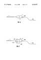
FIG. 4 illustrates a third embodiment of the subject invention in whichcamera head 3 is directly interfaced toendoscope 7 by means ofcoupler 8. In this embodiment,light guide 102 is attached to the back of the camera head enclosure by means ofconnector 206, which is advantageously an easy sealable light interface connector. The light guide extends into the enclosure and then along the endoscope whence it forms a continuous optical path from the light source to the distal tip of the endoscope. As before, it functions to provide illumination to the work site. Meanwhile,splitter 209 splits off a portion of this illumination, andconverter 208 converts this split off portion into electrical energy for powering thecamera head 3.
Advantageously, lightcable input connector 206 is of the type in which the optical face thereof need only be abutted against an adjacent optical window to achieve optical mating therebetween. One example of such a connector is known optical connectors having a metal outside, and a center comprised of either solid glass or a bundle of glass or plastic fibers embedded in epoxy or the like.
FIG. 5 illustrates a fourth embodiment of the subject invention in which thecamera head 3 is coupled toeyepiece 7a ofendoscope 7 by means ofcoupler 8. In this embodiment,light guide 102 is again attached to the back of the camera head enclosure by means ofconnector 206, and a short segment thereof, identified withnumeral 207, connects to the usual endoscopelight input port 213. Thus, again, a continuous optical path is formed from the light source to the distal tip of the endoscope.
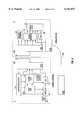
Referring to FIG. 6, a fifth embodiment of a system incorporating the subject invention is illustrated. As shown, thecamera control unit 1 includestiming signal generator 10,power supply 12, processing means such as amicroprocessor 14, sample and holdcircuitry 16, processingcircuitry 18, andsync generator 20. A light source provides optical energy tocamera head 3 by means oflight guide 102. Although this light source is shown in FIG. 6 as being separate fromcontrol unit 1, it should be appreciated that embodiments are possible in which the control unit is contained withincontrol unit 1.
Timinggenerator 10 generates timing signals which are sent to thetiming driver circuitry 30 via the wireless communications interface. Responsive to the timing signals, timingcircuitry 30 generates driving signals which are then provided to theimager 32. Responsive to these driving signals, theimager 32 generates a pre-video signal which is amplified byamplifier 36 and then passed to sample and hold (S/H)circuitry 16 by means of the wireless interface. Responsive to this pre-video signal, the S/H circuitry 16 and theprocessing circuitry 18 generate a video out signal online 50 which is sent to other electronics or to video monitor 9 for display. Additional detail regarding the operation and function of these timing and driving signals is found in U.S. Pat. No. 5,696,553 and co-pending U.S. Ser. No. 08/589,875, previously incorporated herein by reference.
Those skilled in the art will recognize that different components and arrangements thereof may be used in addition to and/or in lieu of those shown in thecontrol unit 1 andcamera head 3 of FIG. 6. For example, it should be appreciated that there are several ways to divide functionality between the camera head and the control unit. According to one approach, the following signals would be transmitted over the wireless interface from the control unit to the camera head: pixel clock, horizontal clock, vertical clock, and electronic shutter pulse. From these, the H1, H2, PG, Vsub, shutter, and V1, V2, V3, V4 signals, each of which is known and need not be explained further, would be derived and applied to the imager. Responsive to these signals, the imager would generate a pre-video signal, which would be then passed to the control unit by means of the wireless interface for processing into a video signal.
Advantageously, the imager is one which only requires one voltage, +5V DC. Such an imager is presently available from Sharp Electronics. However, it should be appreciated that other imagers, such as those requiring voltages other than +5V DC, including +15V, -5V, or -9V DC, are also possible. For such imagers, a standard switch mode power converter would be added to create the +15V, -5V, or -9V DC voltages from a single +5V DC source.
According to a second approach, the following signals would be transmitted from the control unit to the camera head: white balance signal and electronic exposure control signal. Responsive to these signals, at least one of the following signals or combination of signals would be generated and then transmitted to the control unit by means of the wireless interface: the pre-video or composite video signals, the luminance and chrominance video signals, or a digital video signal such as Y:U:V sampled as 4:2:2. An explanation of these signals follows:
1. White balance signal: The white balance signal is a known signal used in the white balance process to adjust the red and blue gain values in thecamera head 3 so that white objects appear colorless. This permits the camera head to be used with various light sources that have different spectral contents. An arc lamp, for example, has more blue than a quartz lamp; thus, the blue gain must be reduced for white to look white. The process is typically initiated before surgery, by pressing a button on the front panel of thecontrol unit 1, and is performed while the user aims the camera head (with endoscope attached) at a gauze or other white object with the intended light source on.
2. Electronic exposure control signal: This is also a known signal, and is used to adjust the picture brightness. It is typically generated by pressing either an increase or decrease button on the front panel ofcontrol unit 1. Once generated, it actuates appropriate circuitry in thecamera head 3 to adjust the picture brightness.
3. Luminance/chrominance signals: These are standard video signals, luminance being the brightness component, and chrominance being the color component. Together they carry the full picture information.
4. Digital Video Signal Y:U:V Sampled At 4:2:2: This is a standard digital video signal.
With reference to FIG. 6, the white balance and electronic exposure control signals originate from themicroprocessor 14 responsive to the pressing of corresponding buttons on the front panel ofcontrol unit 1, while the luminance, chrominance, and digital Y:U:V signals originate from theprocessing circuitry 18.
According to a third approach, the wireless interface would be unidirectional, and provide only for transmission from the camera head to the control unit. Since the wireless interface would be unidirectional, there would be no need for a transmitter in the control unit or a receiver in the camera head. Thus,element 201 in FIG. 6 need only be a transmitter, andelement 210 need only be a receiver. One method of implementing such an approach is to move most if not all of the camera circuitry in the control unit to the camera head, with the camera head sending one or more of the foregoing video or pre-video signals to the control unit, and with the imager being actuated by circuitry within the camera head rather than the control unit.
With reference to FIG. 6, according to this approach, all the elements ofblock 1 would be moved to the camera head. This is currently feasible because of the recent availability of single chip cameras. Thecontrol unit 1 would have a receive, power supply, and part of theprocess 18 circuit to drive the video. In this approach, it is contemplated that the white balance button used to actuate the white balance process could be located on the camera head.
A sixth embodiment of the subject invention involves a generic video camera system, i.e., a video camera system which is utilized in contexts other than in combination with an endoscope. According to one aspect of this embodiment, the camera head is powered at least in part with electrical energy converted from optical energy obtained from a light source. A method of operation in accordance with this aspect is illustrated in FIG. 7. Step 310 comprises providing optical energy from a light source. Step 311 comprises converting the optical energy into electrical energy. Step 312 comprises providing camera electronics including an imager. Step 313 comprises powering at least a portion of the camera electronics with the electrical energy. Step 314 comprises actuating the camera electronics to produce an electronic image. Step 315 comprises processing the electronic image.
According to another aspect of this embodiment, communication between the control unit and the camera head occurs by means of a wireless communications interface. A third aspect involves utilizing the foregoing two aspects in combination. According to this third aspect, communication between the camera head and control unit occurs by means of a wireless communications interface, and the camera head is powered at least in part with electrical energy converted from optical energy provided from a light source. A method of operation in accordance with this third aspect is illustrated in FIG. 8. Step 320 comprises providing optical energy from a light source. Step 321 comprises converting the optical energy into electrical energy. Step 322 comprises providing camera electronics including an imager. Step 323 comprises powering at least a portion of the camera electronics with the electrical energy. Step 324 comprises actuating the camera electronics to produce an electronic image. Step 325 comprises providing control circuity. Step 326 comprises passing the electronic image to the control circuitry through a wireless communications interface.
In light of the foregoing, it can be seen that a video endoscopic system is provided in which the camera head is electrically isolated from the power supply in the control unit. Although a local power supply must now be provided in the camera head, the power which is available and supplied from the same is low enough, that it raises no safety concerns in relation to contact with a patient.
In addition, sincelight guide 102 is lightweight and flexible, and there is no need for an electrical cable to couple the camera head to the control unit, the ability of a surgeon or other user to easily control and manipulate the camera head endoscope combination is dramatically improved.
Finally, the sterilizability of the system is dramatically improved by the avoidance of an electrical cable and the associated breach in the integrity of the housing ofcamera head 3 caused by the coupling of such a cable to the camera head. Althoughlight guide 102 must be coupled to the housing ofcamera head 3, such is readily achieved by an easily sealablelight interface connector 206, which optically mates with the camera head without requiring a breach thereof. Accordingly, a substantial enhancement to the sterilizability of the unit is provided.
While embodiments and applications of this invention have been shown and described, it should be apparent to those of ordinary skill in the art that many of the embodiments are possible without departing from the spirit and scope of the subject invention.
Accordingly, the invention is not to be restricted, except as by the appended claims.
Claims (30)
1. An endoscopic video camera system comprising:
an endoscope;
control circuitry for processing the electronic image as produced by the imager;
a camera head configured for placement along a first optical path extending through the endoscope;
a light source;
a second optical path extending from the light source to the camera head;
the camera head comprising:
camera head electronics including an imager for producing an electronic image; and
a power source for converting at least a portion of the optical energy as transmitted along the second optical path into electrical energy and using the same to power at least part of the camera head electronics, the power source comprising:
a splitter for segregating a portion of the optical energy transmitted along the second optical path; and
a converter for converting the segregated portion of optical energy into electrical energy,
wherein the converter comprises a plurality of photo voltaic cells arranged over an area which is sufficient to deliver necessary power to the camera head electronics given the efficiency of the cells and the intensity of the incident light, and the splitter is configured to allow approximately uniform distribution of light over the cells.
2. The system of claim 1 further comprising a wireless communications interface for allowing wireless communication between the control circuitry and the camera head.
3. The system of claim 2 in which the wireless communications interface is bidirectional.
4. The system of claim 2 in which the wireless communications interface is unidirectional.
5. The system of claim 2 in which the wireless communications interface comprises:
a transceiver and antenna within or coupled to the camera head; and
a transceiver and antenna within or coupled to the control circuitry.
6. The system of claim 1 in which the second optical path comprises a bundle of optical fibers and the splitter comprises at least one of these fibers peeled away from the others.
7. The system of claim 1 in which the second optical path is implemented with a liquid light guide.
8. The system of claim 1 in which the light source is located outside a control unit enclosing the control circuitry.
9. The system of claim 1 in which the light source is located within a control unit enclosing the control circuitry.
10. The system of claim 1 in which the imager is a solid state imager.
11. The system of claim 1 in which the imager is a CCD.
12. The system of claim 1 in which the imager is a CMOS imager.
13. The system of claim 1 in which the imager and camera head electronics are configured on a single chip.
14. The system of claim 1 in which the second optical path extends through the endoscope.
15. The system of claim 1 in which the imager produces an electronic image upon being actuated by the control circuitry.
16. An endoscopic video camera system comprising:
an endoscope;
control circuitry for processing an electronic image as produced by the imager;
a camera head configured for placement along a first optical path extending through the endoscope;
a wireless communications interface for allowing wireless communication between the control circuitry and the camera head;
a light source;
a second optical path extending from the light source to the camera head;
the camera head comprising:
camera head electronics including a solid state imager for producing an electronic image; and
a power source for powering at least a portion of the camera electronics comprising:
a splitter for segregating a portion of the optical energy transmitted along the second optical path; and
a converter for converting the segregated portion of optical energy to electrical energy,
wherein the converter comprises a plurality of photo voltaic cells arranged over an area sufficient to deliver necessary power to the camera head electronics given the efficiency of the cells and the intensity of the incident light, and the splitter is configured to allow approximately uniform distribution of light over the cells.
17. The system of claim 16 in which the imager produces an electronic image upon being actuated by the control circuitry.
18. An endoscopic video camera system comprising:
an endoscope;
control circuitry for processing an electronic image as produced by the imager;
a camera head configured for placement along a first optical path extending through the imager;
a bidirectional wireless communications interface for allowing wireless communication between the control circuitry and the camera head comprising:
a transceiver and antenna within or coupled to the camera head; and
a transceiver and antenna within or coupled to the control circuitry;
a light source;
a second optical path implemented with a bundle of optical fibers extending from the light source to the camera head;
the camera head comprising:
camera head electronics including a CMOS imager integrated on a single chip for producing an electronic image; and
a power source for powering at least a portion of the camera electronics comprising:
a splitter comprising at least one optical fiber of the bundle forming the second optical path configured to segregate a portion of the optical energy transmitted along the second optical path and distribute the segregated light approximately uniformly over an area; and
a plurality of photo voltaic cells placed within the area for converting the segregated portion of optical energy into electrical energy,
wherein the area is determined sufficient to deliver necessary power to the camera head electronics given the efficiency of the cells and the intensity of the incident light, and the splitter is configured to allow approximately uniform distribution of light over the cells.
19. The system of claim 18 in which the imager produces an electronic image upon being actuated by the control circuitry.
20. A method of operating an endoscopic video camera system comprising:
positioning an endoscope having a distal end so that the distal end is in proximity with a work site;
illuminating the work site through optical energy provided from a light source;
actuating camera electronics including an imager to produce an electronic image of a target at the work site;
segregating at least a portion of the optical energy provided from the light source;
converting the segregated portion of optical energy into electrical energy using a plurality of photocells arranged over an area determined sufficient to deliver necessary power to the camera head electronics given the efficiency of the cells and the intensity of the incident light, while having the segregated portion of the optical energy approximately uniformly distributed over the photocells;
powering at least a portion of the camera electronics with the electrical energy; and
processing the electronic image in control circuitry.
21. The method claim 20 further comprising transferring through a wireless communications interface the electronic image to the control circuitry.
22. The method of claim 20 further comprising displaying the image on a monitor.
23. The method of claim 20 further comprising storing the image in a storage device.
24. The method of claim 20 further comprising transmitting the image.
25. A video camera system comprising:
control circuitry for processing the electronic image as produced by the imager;
a camera head configured for placement along a first optical path;
a light source; and
a second optical path extending from the light source to the camera head;
the camera head comprising:
camera head electronics including an imager for producing an electronic image; and
a power source for converting at least a portion of the optical energy as transmitted along the second optical path into electrical energy and using the same to power at least part of the camera head electronics, the power source comprising:
a splitter for segregating at least a portion of the optical energy transmitted along the second optical path; and
a converter for converting the segregated portion of optical energy into electrical energy,
wherein the converter comprises a plurality of photo voltaic cells arranged over an area determined sufficient to deliver necessary power to the camera head electronics given the efficiency of the cells and the intensity of the incident light, and the splitter is configured to allow approximately uniform distribution of light over the cells.
26. The system of claim 25 further comprising a wireless communications interface for allowing wireless communication between the control circuitry and the camera head.
27. The system of claim 25 further comprising an endoscope wherein the first optical path extends through the endoscope.
28. A method of operating a video camera system comprising:
providing optical energy from a light source;
converting said optical energy into electrical energy using a plurality of photocells arranged over an area determined sufficient to deliver necessary power to camera electronics given the efficiency of the cells and the intensity of the incident light, while having at least of portion of said optical energy approximately uniformly distributed over the plurality of photocells;
providing camera electronics including an imager; powering at least a portion of the camera electronics with the electrical energy; actuating the camera electronics to produce an electronic image; and processing the electronic image.
29. The method of claim 28 further comprising passing the electronic image to control circuitry through a wireless communications interface.
30. A method of reducing electromagnetic interference in a video camera system comprising:
providing optical energy from a light source;
converting said optical energy into electrical energy using a plurality of photocells arranged over an area determined sufficient to deliver necessary power to camera electronics given the efficiency of the cells and the intensity of the incident light, while having at least a portion of said optical energy substantially uniformly distributed over the plurality of photocells;
providing camera electronics including an imager;
powering at least a portion of the camera electronics with the electrical energy;
actuating the camera electronics to produce an electronic image;
providing control circuitry; and
passing the electronic image to the control circuitry through a wireless communication interface.
Priority Applications (1)
| Application Number | Priority Date | Filing Date | Title |
|---|---|---|---|
| US09/044,090US6141037A (en) | 1998-03-18 | 1998-03-18 | Video camera system and related method |
Applications Claiming Priority (1)
| Application Number | Priority Date | Filing Date | Title |
|---|---|---|---|
| US09/044,090US6141037A (en) | 1998-03-18 | 1998-03-18 | Video camera system and related method |
Publications (1)
| Publication Number | Publication Date |
|---|---|
| US6141037Atrue US6141037A (en) | 2000-10-31 |
Family
ID=21930479
Family Applications (1)
| Application Number | Title | Priority Date | Filing Date |
|---|---|---|---|
| US09/044,090Expired - LifetimeUS6141037A (en) | 1998-03-18 | 1998-03-18 | Video camera system and related method |
Country Status (1)
| Country | Link |
|---|---|
| US (1) | US6141037A (en) |
Cited By (96)
| Publication number | Priority date | Publication date | Assignee | Title |
|---|---|---|---|---|
| US6211904B1 (en)* | 1997-09-11 | 2001-04-03 | Edwin L. Adair | Surgical devices incorporating reduced area imaging devices |
| US6310642B1 (en)* | 1997-11-24 | 2001-10-30 | Micro-Medical Devices, Inc. | Reduced area imaging devices incorporated within surgical instruments |
| US20020067408A1 (en)* | 1997-10-06 | 2002-06-06 | Adair Edwin L. | Hand-held computers incorporating reduced area imaging devices |
| US20020080248A1 (en)* | 1997-11-24 | 2002-06-27 | Adair Edwin L. | Reduced area imaging devices utilizing selected charge integration periods |
| US20020089589A1 (en)* | 1997-10-06 | 2002-07-11 | Adair Edwin L. | Communication devices incorporating reduced area imaging devices |
| US6424369B1 (en)* | 1997-10-06 | 2002-07-23 | Edwin L. Adair | Hand-held computers incorporating reduced area imaging devices |
| US6452626B1 (en)* | 1997-10-06 | 2002-09-17 | Edwin L. Adair | Communication devices incorporating reduced area imaging devices |
| US20030009086A1 (en)* | 2001-06-01 | 2003-01-09 | Black Michael D. | Non-tethered macro-to-micro endoscope |
| US20030062476A1 (en)* | 2001-09-28 | 2003-04-03 | Wang Jang Yi | Remote control electron microscope |
| US6589162B2 (en)* | 2000-02-21 | 2003-07-08 | Pentax Corporation | Endoscope system and video camera for endoscope |
| US20030137723A1 (en)* | 2002-01-22 | 2003-07-24 | Ulrich Sander | Transmission device for a surgical microscope |
| US20030174205A1 (en)* | 2002-03-12 | 2003-09-18 | Amling Marc R. | Endoscope reader |
| WO2002055126A3 (en)* | 2001-01-11 | 2004-01-15 | Given Imaging Ltd | Device and system for in-vivo procedures |
| US20040047313A1 (en)* | 2002-09-10 | 2004-03-11 | Harris Corporation | Communication system providing hybrid optical/wireless communications and related methods |
| US6714260B1 (en)* | 1998-07-23 | 2004-03-30 | Conexant Systems, Inc. | Monolithic generation of RF for wireless transmission of video |
| US20040085441A1 (en)* | 2000-04-10 | 2004-05-06 | Olympus Optical, Co., Ltd. | Endoscope apparatus |
| US20040263680A1 (en)* | 2003-06-30 | 2004-12-30 | Elazer Sonnenschein | Autoclavable imager assembly |
| US7038716B2 (en) | 1999-07-30 | 2006-05-02 | Pixim, Inc. | Mobile device equipped with digital image sensor |
| US20070030345A1 (en)* | 2002-03-12 | 2007-02-08 | Karl Storz Imaging, Inc. | Universal scope reader |
| US7241263B2 (en) | 2004-09-30 | 2007-07-10 | Scimed Life Systems, Inc. | Selectively rotatable shaft coupler |
| US20080139881A1 (en)* | 2006-11-16 | 2008-06-12 | Reid Cover | Wireless endoscopic camera |
| US20080194915A1 (en)* | 2004-04-05 | 2008-08-14 | Michael Joseph Blackhurst | Scope Warming Device |
| US7413543B2 (en) | 2003-04-01 | 2008-08-19 | Scimed Life Systems, Inc. | Endoscope with actively cooled illumination sources |
| US20080211634A1 (en)* | 2002-03-12 | 2008-09-04 | Vernon Hopkins | Auto recognition of a shaver blade for medical use |
| US7479106B2 (en) | 2004-09-30 | 2009-01-20 | Boston Scientific Scimed, Inc. | Automated control of irrigation and aspiration in a single-use endoscope |
| US7578786B2 (en) | 2003-04-01 | 2009-08-25 | Boston Scientific Scimed, Inc. | Video endoscope |
| US7591783B2 (en) | 2003-04-01 | 2009-09-22 | Boston Scientific Scimed, Inc. | Articulation joint for video endoscope |
| US20090247824A1 (en)* | 2008-03-27 | 2009-10-01 | Olympus Corporation | Wireless image acquisition system |
| US7597662B2 (en) | 2004-09-30 | 2009-10-06 | Boston Scientific Scimed, Inc. | Multi-fluid delivery system |
| US20090326561A1 (en)* | 2008-06-27 | 2009-12-31 | Ethicon Endo-Surgery, Inc. | Surgical suture arrangement |
| US20100141744A1 (en)* | 2002-03-12 | 2010-06-10 | Amling Marc R | Wireless Camera Coupling |
| US7846107B2 (en) | 2005-05-13 | 2010-12-07 | Boston Scientific Scimed, Inc. | Endoscopic apparatus with integrated multiple biopsy device |
| US20110034769A1 (en)* | 1997-10-06 | 2011-02-10 | Micro-Imaging Solutions Llc | Reduced area imaging device incorporated within wireless endoscopic devices |
| US20110115891A1 (en)* | 2009-11-13 | 2011-05-19 | Ethicon Endo-Surgery, Inc. | Energy delivery apparatus, system, and method for deployable medical electronic devices |
| US7955255B2 (en) | 2006-04-20 | 2011-06-07 | Boston Scientific Scimed, Inc. | Imaging assembly with transparent distal cap |
| US7967759B2 (en) | 2006-01-19 | 2011-06-28 | Boston Scientific Scimed, Inc. | Endoscopic system with integrated patient respiratory status indicator |
| US20110193948A1 (en)* | 2002-03-12 | 2011-08-11 | Amling Marc R | Wireless Camera Coupling With Rotatable Coupling |
| US8052597B2 (en) | 2005-08-30 | 2011-11-08 | Boston Scientific Scimed, Inc. | Method for forming an endoscope articulation joint |
| US8083671B2 (en) | 2004-09-30 | 2011-12-27 | Boston Scientific Scimed, Inc. | Fluid delivery system for use with an endoscope |
| US8097003B2 (en) | 2005-05-13 | 2012-01-17 | Boston Scientific Scimed, Inc. | Endoscopic apparatus with integrated variceal ligation device |
| US8118732B2 (en) | 2003-04-01 | 2012-02-21 | Boston Scientific Scimed, Inc. | Force feedback control system for video endoscope |
| US8199187B2 (en) | 2004-09-30 | 2012-06-12 | Boston Scientific Scimed, Inc. | Adapter for use with digital imaging medical device |
| US8202265B2 (en) | 2006-04-20 | 2012-06-19 | Boston Scientific Scimed, Inc. | Multiple lumen assembly for use in endoscopes or other medical devices |
| US8353860B2 (en) | 2004-09-30 | 2013-01-15 | Boston Scientific Scimed, Inc. | Device for obstruction removal with specific tip structure |
| US8353487B2 (en) | 2009-12-17 | 2013-01-15 | Ethicon Endo-Surgery, Inc. | User interface support devices for endoscopic surgical instruments |
| US8357148B2 (en) | 2004-09-30 | 2013-01-22 | Boston Scientific Scimed, Inc. | Multi-functional endoscopic system for use in electrosurgical applications |
| US8363097B2 (en) | 2009-07-23 | 2013-01-29 | Smith & Nephew, Inc. | Endoscopic imaging system |
| US8403926B2 (en) | 2008-06-05 | 2013-03-26 | Ethicon Endo-Surgery, Inc. | Manually articulating devices |
| US8409200B2 (en) | 2008-09-03 | 2013-04-02 | Ethicon Endo-Surgery, Inc. | Surgical grasping device |
| US8425505B2 (en) | 2007-02-15 | 2013-04-23 | Ethicon Endo-Surgery, Inc. | Electroporation ablation apparatus, system, and method |
| EP2502419A4 (en)* | 2009-06-16 | 2013-05-08 | Leonard Pool | Intrinsically safe video inspection system |
| US8480657B2 (en) | 2007-10-31 | 2013-07-09 | Ethicon Endo-Surgery, Inc. | Detachable distal overtube section and methods for forming a sealable opening in the wall of an organ |
| US8496574B2 (en) | 2009-12-17 | 2013-07-30 | Ethicon Endo-Surgery, Inc. | Selectively positionable camera for surgical guide tube assembly |
| US8506564B2 (en) | 2009-12-18 | 2013-08-13 | Ethicon Endo-Surgery, Inc. | Surgical instrument comprising an electrode |
| US8535219B2 (en) | 2003-04-01 | 2013-09-17 | Boston Scientific Scimed, Inc. | Fluid manifold for endoscope system |
| US8579897B2 (en) | 2007-11-21 | 2013-11-12 | Ethicon Endo-Surgery, Inc. | Bipolar forceps |
| US8608652B2 (en) | 2009-11-05 | 2013-12-17 | Ethicon Endo-Surgery, Inc. | Vaginal entry surgical devices, kit, system, and method |
| US8679003B2 (en) | 2008-05-30 | 2014-03-25 | Ethicon Endo-Surgery, Inc. | Surgical device and endoscope including same |
| US8771260B2 (en) | 2008-05-30 | 2014-07-08 | Ethicon Endo-Surgery, Inc. | Actuating and articulating surgical device |
| US8888684B2 (en) | 2006-03-27 | 2014-11-18 | Boston Scientific Scimed, Inc. | Medical devices with local drug delivery capabilities |
| US8906035B2 (en) | 2008-06-04 | 2014-12-09 | Ethicon Endo-Surgery, Inc. | Endoscopic drop off bag |
| US8939897B2 (en) | 2007-10-31 | 2015-01-27 | Ethicon Endo-Surgery, Inc. | Methods for closing a gastrotomy |
| US9005198B2 (en) | 2010-01-29 | 2015-04-14 | Ethicon Endo-Surgery, Inc. | Surgical instrument comprising an electrode |
| US9011431B2 (en) | 2009-01-12 | 2015-04-21 | Ethicon Endo-Surgery, Inc. | Electrical ablation devices |
| US9028483B2 (en) | 2009-12-18 | 2015-05-12 | Ethicon Endo-Surgery, Inc. | Surgical instrument comprising an electrode |
| US20150130991A1 (en)* | 2013-11-12 | 2015-05-14 | Canon Kabushiki Kaisha | Image pickup system |
| US9049987B2 (en) | 2011-03-17 | 2015-06-09 | Ethicon Endo-Surgery, Inc. | Hand held surgical device for manipulating an internal magnet assembly within a patient |
| US9078662B2 (en) | 2012-07-03 | 2015-07-14 | Ethicon Endo-Surgery, Inc. | Endoscopic cap electrode and method for using the same |
| US20150362172A1 (en)* | 2014-06-16 | 2015-12-17 | Owls Ag International Marketing & Consulting | Apparatus and method embedding a camera in an led streetlight |
| US9220526B2 (en) | 2008-11-25 | 2015-12-29 | Ethicon Endo-Surgery, Inc. | Rotational coupling device for surgical instrument with flexible actuators |
| US9233241B2 (en) | 2011-02-28 | 2016-01-12 | Ethicon Endo-Surgery, Inc. | Electrical ablation devices and methods |
| US9254169B2 (en) | 2011-02-28 | 2016-02-09 | Ethicon Endo-Surgery, Inc. | Electrical ablation devices and methods |
| US9277957B2 (en) | 2012-08-15 | 2016-03-08 | Ethicon Endo-Surgery, Inc. | Electrosurgical devices and methods |
| US9314620B2 (en) | 2011-02-28 | 2016-04-19 | Ethicon Endo-Surgery, Inc. | Electrical ablation devices and methods |
| US20160213230A1 (en)* | 1997-10-06 | 2016-07-28 | Micro-Imaging Solutions, Llc | Reduced area imaging device incorporated within endoscopic devices |
| US9427255B2 (en) | 2012-05-14 | 2016-08-30 | Ethicon Endo-Surgery, Inc. | Apparatus for introducing a steerable camera assembly into a patient |
| US20160278615A1 (en)* | 2013-02-05 | 2016-09-29 | Scopernicus, LLC | Wireless endoscopic surgical device |
| US20160367115A1 (en)* | 2015-06-17 | 2016-12-22 | Fujifilm Corporation | Connector |
| US20160367116A1 (en)* | 2015-06-17 | 2016-12-22 | Fujifilm Corporation | Connector |
| US9545290B2 (en) | 2012-07-30 | 2017-01-17 | Ethicon Endo-Surgery, Inc. | Needle probe guide |
| US9572623B2 (en) | 2012-08-02 | 2017-02-21 | Ethicon Endo-Surgery, Inc. | Reusable electrode and disposable sheath |
| US20170191875A1 (en)* | 2008-12-26 | 2017-07-06 | Fluke Corporation | Infrared imaging probe |
| US20170318205A1 (en)* | 2016-04-27 | 2017-11-02 | Karl Storz Imaging, Inc. | Light Device and System For Providing Light to Optical Scopes |
| US20180000319A1 (en)* | 2016-06-30 | 2018-01-04 | Karl Storz Gmbh & Co. Kg | Apparatus For Video-Endoscopy |
| CN108200349A (en)* | 2018-03-20 | 2018-06-22 | 浙江国自机器人技术有限公司 | A kind of POE power supplies camera |
| US10092291B2 (en) | 2011-01-25 | 2018-10-09 | Ethicon Endo-Surgery, Inc. | Surgical instrument with selectively rigidizable features |
| US10098527B2 (en) | 2013-02-27 | 2018-10-16 | Ethidcon Endo-Surgery, Inc. | System for performing a minimally invasive surgical procedure |
| US10105141B2 (en) | 2008-07-14 | 2018-10-23 | Ethicon Endo-Surgery, Inc. | Tissue apposition clip application methods |
| CN109717827A (en)* | 2019-02-26 | 2019-05-07 | 上海欧太医疗器械有限公司 | Fine soft video laryngoscope |
| US10314649B2 (en) | 2012-08-02 | 2019-06-11 | Ethicon Endo-Surgery, Inc. | Flexible expandable electrode and method of intraluminal delivery of pulsed power |
| US10638024B1 (en)* | 2016-03-30 | 2020-04-28 | Uemsi/Htv | Pole mounted lighted camera |
| US10779882B2 (en) | 2009-10-28 | 2020-09-22 | Ethicon Endo-Surgery, Inc. | Electrical ablation devices |
| US11382492B2 (en) | 2013-02-05 | 2022-07-12 | Scopernicus, LLC | Wireless endoscopic surgical device |
| EP4032458A1 (en)* | 2021-01-25 | 2022-07-27 | Tympany Medical Limited | Medical instruments |
| WO2022157393A1 (en)* | 2021-01-25 | 2022-07-28 | Tympany Medical Limited | Medical instruments |
| US20230023904A1 (en)* | 2021-07-23 | 2023-01-26 | Phaox LLC | Handheld wireless endoscope image streaming apparatus |
Citations (25)
| Publication number | Priority date | Publication date | Assignee | Title |
|---|---|---|---|---|
| US4170997A (en)* | 1977-08-26 | 1979-10-16 | Hughes Aircraft Company | Medical laser instrument for transmitting infrared laser energy to a selected part of the body |
| US4349014A (en)* | 1979-10-02 | 1982-09-14 | Olympus Optical Co., Ltd. | Endoscope system |
| US4633304A (en)* | 1983-08-27 | 1986-12-30 | Olympus Optical Co., Ltd. | Endoscope assembly |
| US4677471A (en)* | 1985-08-16 | 1987-06-30 | Olympus Optical Co., Ltd. | Endoscope |
| US4831456A (en)* | 1986-12-08 | 1989-05-16 | Olympus Optical Co., Ltd. | Imaging apparatus using a solid-state imaging element having a substrate |
| US4846571A (en)* | 1986-11-03 | 1989-07-11 | Raytheon Company | AM-FM laser |
| US4878485A (en)* | 1989-02-03 | 1989-11-07 | Adair Edwin Lloyd | Rigid video endoscope with heat sterilizable sheath |
| US4895138A (en)* | 1985-01-14 | 1990-01-23 | Olympus Optical Co., Ltd. | Endoscope with a detachable observation unit at its distal end |
| US4918521A (en)* | 1987-01-20 | 1990-04-17 | Olympus Optical Co., Ltd. | Solid state imaging apparatus |
| US4931867A (en)* | 1988-03-01 | 1990-06-05 | Olympus Optical Co., Ltd. | Electronic endoscope apparatus having an isolation circuit for isolating a patient circuit from a secondary circuit |
| US4975926A (en)* | 1989-03-30 | 1990-12-04 | Guenther Knapp | Wireless indoor data communication system |
| US4977418A (en)* | 1989-10-03 | 1990-12-11 | Canty Thomas M | Camera viewing unit |
| US4977618A (en)* | 1988-04-21 | 1990-12-11 | Photonics Corporation | Infrared data communications |
| US5027433A (en)* | 1988-04-04 | 1991-06-25 | Hm Electronics, Inc. | Remote infrared transceiver and method of using same |
| US5089895A (en)* | 1990-05-07 | 1992-02-18 | Cues, Inc. | Encapsulated television camera and method and apparatus for fabricating same |
| US5231393A (en)* | 1988-10-18 | 1993-07-27 | P.A.T., Co. | Mobile speed awareness device |
| US5257100A (en)* | 1990-09-28 | 1993-10-26 | Olympus Optical Co., Ltd. | Apparatus for reducing network patterns from the image of a fiber scope |
| US5428386A (en)* | 1992-08-24 | 1995-06-27 | Envision Medical Corporation | Remote 3D video camera system |
| US5536244A (en)* | 1993-06-26 | 1996-07-16 | Richard Wolf Gmbh | Endoscopic instrument with improved closure window |
| US5587736A (en)* | 1993-02-16 | 1996-12-24 | Envision Medical Corporation | Sterilizable CCD video camera |
| US5696553A (en)* | 1992-09-25 | 1997-12-09 | Bristol-Myers Squibb Co. | Remote imager video camera cable compensation circuitry |
| US5841491A (en)* | 1993-10-14 | 1998-11-24 | Envision Medical Corp. | Fiberscope enhancement system |
| US5868664A (en)* | 1996-02-23 | 1999-02-09 | Envision Medical Corporation | Electrically isolated sterilizable endoscopic video camera head |
| US5882305A (en)* | 1996-09-09 | 1999-03-16 | General Electric Company | Optical coupling for invasive devices |
| US6073569A (en)* | 1998-02-26 | 2000-06-13 | Murata Electric Boatworks Llc | Advantageous use of battery mass in electric watercraft |
- 1998
- 1998-03-18USUS09/044,090patent/US6141037A/ennot_activeExpired - Lifetime
Patent Citations (25)
| Publication number | Priority date | Publication date | Assignee | Title |
|---|---|---|---|---|
| US4170997A (en)* | 1977-08-26 | 1979-10-16 | Hughes Aircraft Company | Medical laser instrument for transmitting infrared laser energy to a selected part of the body |
| US4349014A (en)* | 1979-10-02 | 1982-09-14 | Olympus Optical Co., Ltd. | Endoscope system |
| US4633304A (en)* | 1983-08-27 | 1986-12-30 | Olympus Optical Co., Ltd. | Endoscope assembly |
| US4895138A (en)* | 1985-01-14 | 1990-01-23 | Olympus Optical Co., Ltd. | Endoscope with a detachable observation unit at its distal end |
| US4677471A (en)* | 1985-08-16 | 1987-06-30 | Olympus Optical Co., Ltd. | Endoscope |
| US4846571A (en)* | 1986-11-03 | 1989-07-11 | Raytheon Company | AM-FM laser |
| US4831456A (en)* | 1986-12-08 | 1989-05-16 | Olympus Optical Co., Ltd. | Imaging apparatus using a solid-state imaging element having a substrate |
| US4918521A (en)* | 1987-01-20 | 1990-04-17 | Olympus Optical Co., Ltd. | Solid state imaging apparatus |
| US4931867A (en)* | 1988-03-01 | 1990-06-05 | Olympus Optical Co., Ltd. | Electronic endoscope apparatus having an isolation circuit for isolating a patient circuit from a secondary circuit |
| US5027433A (en)* | 1988-04-04 | 1991-06-25 | Hm Electronics, Inc. | Remote infrared transceiver and method of using same |
| US4977618A (en)* | 1988-04-21 | 1990-12-11 | Photonics Corporation | Infrared data communications |
| US5231393A (en)* | 1988-10-18 | 1993-07-27 | P.A.T., Co. | Mobile speed awareness device |
| US4878485A (en)* | 1989-02-03 | 1989-11-07 | Adair Edwin Lloyd | Rigid video endoscope with heat sterilizable sheath |
| US4975926A (en)* | 1989-03-30 | 1990-12-04 | Guenther Knapp | Wireless indoor data communication system |
| US4977418A (en)* | 1989-10-03 | 1990-12-11 | Canty Thomas M | Camera viewing unit |
| US5089895A (en)* | 1990-05-07 | 1992-02-18 | Cues, Inc. | Encapsulated television camera and method and apparatus for fabricating same |
| US5257100A (en)* | 1990-09-28 | 1993-10-26 | Olympus Optical Co., Ltd. | Apparatus for reducing network patterns from the image of a fiber scope |
| US5428386A (en)* | 1992-08-24 | 1995-06-27 | Envision Medical Corporation | Remote 3D video camera system |
| US5696553A (en)* | 1992-09-25 | 1997-12-09 | Bristol-Myers Squibb Co. | Remote imager video camera cable compensation circuitry |
| US5587736A (en)* | 1993-02-16 | 1996-12-24 | Envision Medical Corporation | Sterilizable CCD video camera |
| US5536244A (en)* | 1993-06-26 | 1996-07-16 | Richard Wolf Gmbh | Endoscopic instrument with improved closure window |
| US5841491A (en)* | 1993-10-14 | 1998-11-24 | Envision Medical Corp. | Fiberscope enhancement system |
| US5868664A (en)* | 1996-02-23 | 1999-02-09 | Envision Medical Corporation | Electrically isolated sterilizable endoscopic video camera head |
| US5882305A (en)* | 1996-09-09 | 1999-03-16 | General Electric Company | Optical coupling for invasive devices |
| US6073569A (en)* | 1998-02-26 | 2000-06-13 | Murata Electric Boatworks Llc | Advantageous use of battery mass in electric watercraft |
Cited By (181)
| Publication number | Priority date | Publication date | Assignee | Title |
|---|---|---|---|---|
| US6211904B1 (en)* | 1997-09-11 | 2001-04-03 | Edwin L. Adair | Surgical devices incorporating reduced area imaging devices |
| US20110034769A1 (en)* | 1997-10-06 | 2011-02-10 | Micro-Imaging Solutions Llc | Reduced area imaging device incorporated within wireless endoscopic devices |
| US6862036B2 (en) | 1997-10-06 | 2005-03-01 | Edwin L. Adair | Communication devices incorporating reduced area imaging devices |
| US20140364689A1 (en)* | 1997-10-06 | 2014-12-11 | Micro-Imaging Solutions Llc | Reduced area imaging device incorporated within endoscopic devices |
| US20020089589A1 (en)* | 1997-10-06 | 2002-07-11 | Adair Edwin L. | Communication devices incorporating reduced area imaging devices |
| US6424369B1 (en)* | 1997-10-06 | 2002-07-23 | Edwin L. Adair | Hand-held computers incorporating reduced area imaging devices |
| US6452626B1 (en)* | 1997-10-06 | 2002-09-17 | Edwin L. Adair | Communication devices incorporating reduced area imaging devices |
| US8885034B2 (en)* | 1997-10-06 | 2014-11-11 | Micro-Imaging Solutions Llc | Reduced area imaging device incorporated within endoscopic devices |
| US9186052B1 (en) | 1997-10-06 | 2015-11-17 | Micro-Imagaing Solutions | Reduced area imaging device incorporated within endoscopic devices |
| US7002621B2 (en)* | 1997-10-06 | 2006-02-21 | Adair Edwin L | Communication devices incorporating reduced area imaging devices |
| US9667896B2 (en)* | 1997-10-06 | 2017-05-30 | Cellect Llc | Reduced area imaging device incorporated within endoscopic devices |
| US20130144122A1 (en)* | 1997-10-06 | 2013-06-06 | Micro-Imaging Solutions Llc | Reduced area imaging device incorporated within endoscopic devices |
| US6982742B2 (en)* | 1997-10-06 | 2006-01-03 | Adair Edwin L | Hand-held computers incorporating reduced area imaging devices |
| US20020067408A1 (en)* | 1997-10-06 | 2002-06-06 | Adair Edwin L. | Hand-held computers incorporating reduced area imaging devices |
| US9307895B2 (en)* | 1997-10-06 | 2016-04-12 | Micro-Imaging Solutions, Llc | Reduced area imaging device incorporated within endoscopic devices |
| US9198565B2 (en) | 1997-10-06 | 2015-12-01 | Micro-Imaging Solutions | Reduced area imaging device incorporated within endoscopic devices |
| US20160213230A1 (en)* | 1997-10-06 | 2016-07-28 | Micro-Imaging Solutions, Llc | Reduced area imaging device incorporated within endoscopic devices |
| US6310642B1 (en)* | 1997-11-24 | 2001-10-30 | Micro-Medical Devices, Inc. | Reduced area imaging devices incorporated within surgical instruments |
| WO2003030525A1 (en)* | 1997-11-24 | 2003-04-10 | Micro-Medical Devices, Inc. | Reduced area imaging devices utilizing selected charge integration periods |
| US20020080248A1 (en)* | 1997-11-24 | 2002-06-27 | Adair Edwin L. | Reduced area imaging devices utilizing selected charge integration periods |
| US6982740B2 (en)* | 1997-11-24 | 2006-01-03 | Micro-Medical Devices, Inc. | Reduced area imaging devices utilizing selected charge integration periods |
| US6714260B1 (en)* | 1998-07-23 | 2004-03-30 | Conexant Systems, Inc. | Monolithic generation of RF for wireless transmission of video |
| US7038716B2 (en) | 1999-07-30 | 2006-05-02 | Pixim, Inc. | Mobile device equipped with digital image sensor |
| US6589162B2 (en)* | 2000-02-21 | 2003-07-08 | Pentax Corporation | Endoscope system and video camera for endoscope |
| US20040085441A1 (en)* | 2000-04-10 | 2004-05-06 | Olympus Optical, Co., Ltd. | Endoscope apparatus |
| US6840901B2 (en)* | 2000-04-10 | 2005-01-11 | Olympus Corporation | Endoscope apparatus |
| US20050080342A1 (en)* | 2001-01-11 | 2005-04-14 | Gilreath Mark G. | Device and system for in-vivo procedures |
| JP2004524076A (en)* | 2001-01-11 | 2004-08-12 | ギブン・イメージング・リミテツド | Apparatus and system for in vivo procedures |
| WO2002055126A3 (en)* | 2001-01-11 | 2004-01-15 | Given Imaging Ltd | Device and system for in-vivo procedures |
| US6869397B2 (en) | 2001-06-01 | 2005-03-22 | The Board Of Trustees Of The Leland Stanford Junior University | Non-tethered macro-to-micro endoscope |
| US20030009086A1 (en)* | 2001-06-01 | 2003-01-09 | Black Michael D. | Non-tethered macro-to-micro endoscope |
| US20030062476A1 (en)* | 2001-09-28 | 2003-04-03 | Wang Jang Yi | Remote control electron microscope |
| US20030137723A1 (en)* | 2002-01-22 | 2003-07-24 | Ulrich Sander | Transmission device for a surgical microscope |
| US20030174205A1 (en)* | 2002-03-12 | 2003-09-18 | Amling Marc R. | Endoscope reader |
| US9510740B2 (en) | 2002-03-12 | 2016-12-06 | Karl Storz Endovision, Inc. | Auto recognition of a shaver blade for medical use |
| US8599250B2 (en) | 2002-03-12 | 2013-12-03 | Karl Storz Imaging, Inc. | Wireless camera coupling |
| US20080211634A1 (en)* | 2002-03-12 | 2008-09-04 | Vernon Hopkins | Auto recognition of a shaver blade for medical use |
| US20070030345A1 (en)* | 2002-03-12 | 2007-02-08 | Karl Storz Imaging, Inc. | Universal scope reader |
| US9271630B2 (en) | 2002-03-12 | 2016-03-01 | Karl Storz Imaging, Inc. | Wireless camera coupling with rotatable coupling |
| US20110193948A1 (en)* | 2002-03-12 | 2011-08-11 | Amling Marc R | Wireless Camera Coupling With Rotatable Coupling |
| US8194122B2 (en) | 2002-03-12 | 2012-06-05 | Karl Storz Imaging, Inc. | Universal scope reader |
| US8723936B2 (en)* | 2002-03-12 | 2014-05-13 | Karl Storz Imaging, Inc. | Wireless camera coupling with rotatable coupling |
| US20100141744A1 (en)* | 2002-03-12 | 2010-06-10 | Amling Marc R | Wireless Camera Coupling |
| US7289139B2 (en)* | 2002-03-12 | 2007-10-30 | Karl Storz Imaging, Inc. | Endoscope reader |
| WO2003101280A3 (en)* | 2002-05-31 | 2004-07-08 | Univ Leland Stanford Junior | A non-tethered macro-to-micro endoscope |
| US20040047313A1 (en)* | 2002-09-10 | 2004-03-11 | Harris Corporation | Communication system providing hybrid optical/wireless communications and related methods |
| US20090232508A1 (en)* | 2002-09-10 | 2009-09-17 | Harris Corporation | Communication system providing hybrid optical/wireless communications and related methods |
| US7583642B2 (en)* | 2002-09-10 | 2009-09-01 | Harris Corporation | Communication system providing hybrid optical/wireless communications and related methods |
| US8050244B2 (en) | 2002-09-10 | 2011-11-01 | Harris Corporation | Communication system providing hybrid optical/wireless communications and related methods |
| US11324395B2 (en) | 2003-04-01 | 2022-05-10 | Boston Scientific Scimed, Inc. | Endoscopic imaging system |
| US8475366B2 (en) | 2003-04-01 | 2013-07-02 | Boston Scientific Scimed, Inc. | Articulation joint for a medical device |
| US8608648B2 (en) | 2003-04-01 | 2013-12-17 | Boston Scientific Scimed, Inc. | Articulation joint |
| US10765307B2 (en) | 2003-04-01 | 2020-09-08 | Boston Scientific Scimed, Inc. | Endoscopic imaging system |
| US8425408B2 (en) | 2003-04-01 | 2013-04-23 | Boston Scientific Scimed, Inc. | Articulation joint for video endoscope |
| US7591783B2 (en) | 2003-04-01 | 2009-09-22 | Boston Scientific Scimed, Inc. | Articulation joint for video endoscope |
| US7578786B2 (en) | 2003-04-01 | 2009-08-25 | Boston Scientific Scimed, Inc. | Video endoscope |
| US8118732B2 (en) | 2003-04-01 | 2012-02-21 | Boston Scientific Scimed, Inc. | Force feedback control system for video endoscope |
| US7413543B2 (en) | 2003-04-01 | 2008-08-19 | Scimed Life Systems, Inc. | Endoscope with actively cooled illumination sources |
| US8535219B2 (en) | 2003-04-01 | 2013-09-17 | Boston Scientific Scimed, Inc. | Fluid manifold for endoscope system |
| US8622894B2 (en) | 2003-04-01 | 2014-01-07 | Boston Scientific Scimed, Inc. | Articulation joint |
| US9913573B2 (en) | 2003-04-01 | 2018-03-13 | Boston Scientific Scimed, Inc. | Endoscopic imaging system |
| US7369176B2 (en)* | 2003-06-30 | 2008-05-06 | Medigus Ltd. | Autoclavable imager assembly |
| WO2005002210A1 (en)* | 2003-06-30 | 2005-01-06 | Medigus Ltd. | Autoclavable imager assembly |
| US20040263680A1 (en)* | 2003-06-30 | 2004-12-30 | Elazer Sonnenschein | Autoclavable imager assembly |
| US20080194915A1 (en)* | 2004-04-05 | 2008-08-14 | Michael Joseph Blackhurst | Scope Warming Device |
| US9060676B2 (en)* | 2004-04-05 | 2015-06-23 | Fisher & Paykel Healthcare Limited | Scope warming device with whitening element |
| US9993146B2 (en) | 2004-04-05 | 2018-06-12 | Fisher & Paykel Healthcare Limited | Scope warming device |
| US8199187B2 (en) | 2004-09-30 | 2012-06-12 | Boston Scientific Scimed, Inc. | Adapter for use with digital imaging medical device |
| US8197400B2 (en) | 2004-09-30 | 2012-06-12 | Boston Scientific Scimed, Inc. | Selectively rotatable shaft coupler |
| US8083671B2 (en) | 2004-09-30 | 2011-12-27 | Boston Scientific Scimed, Inc. | Fluid delivery system for use with an endoscope |
| US7597662B2 (en) | 2004-09-30 | 2009-10-06 | Boston Scientific Scimed, Inc. | Multi-fluid delivery system |
| US8435172B2 (en) | 2004-09-30 | 2013-05-07 | Boston Scientific Scimed, Inc. | Automated control of irrigation and aspiration in a single-use endoscope |
| US8357148B2 (en) | 2004-09-30 | 2013-01-22 | Boston Scientific Scimed, Inc. | Multi-functional endoscopic system for use in electrosurgical applications |
| US7479106B2 (en) | 2004-09-30 | 2009-01-20 | Boston Scientific Scimed, Inc. | Automated control of irrigation and aspiration in a single-use endoscope |
| US7241263B2 (en) | 2004-09-30 | 2007-07-10 | Scimed Life Systems, Inc. | Selectively rotatable shaft coupler |
| US8353860B2 (en) | 2004-09-30 | 2013-01-15 | Boston Scientific Scimed, Inc. | Device for obstruction removal with specific tip structure |
| USRE46007E1 (en) | 2004-09-30 | 2016-05-24 | Boston Scientific Scimed, Inc. | Automated control of irrigation and aspiration in a single-use endoscope |
| US7846107B2 (en) | 2005-05-13 | 2010-12-07 | Boston Scientific Scimed, Inc. | Endoscopic apparatus with integrated multiple biopsy device |
| US8097003B2 (en) | 2005-05-13 | 2012-01-17 | Boston Scientific Scimed, Inc. | Endoscopic apparatus with integrated variceal ligation device |
| US8585715B2 (en) | 2005-05-13 | 2013-11-19 | Boston Scientific Scimed, Inc. | Endoscopic apparatus with integrated variceal ligation device |
| US11957312B2 (en) | 2005-08-30 | 2024-04-16 | Boston Scientific Scimed, Inc. | Method for forming an endoscope articulation joint |
| US11191424B2 (en) | 2005-08-30 | 2021-12-07 | Boston Scientific Scimed, Inc. | Method for forming an endoscope articulation joint |
| US9439557B2 (en) | 2005-08-30 | 2016-09-13 | Boston Scientific Scimed, Inc. | Articulation joint |
| US8052597B2 (en) | 2005-08-30 | 2011-11-08 | Boston Scientific Scimed, Inc. | Method for forming an endoscope articulation joint |
| US10052013B2 (en) | 2005-08-30 | 2018-08-21 | Boston Scientific Scimed, Inc. | Medical device comprising segments |
| US7967759B2 (en) | 2006-01-19 | 2011-06-28 | Boston Scientific Scimed, Inc. | Endoscopic system with integrated patient respiratory status indicator |
| US8888684B2 (en) | 2006-03-27 | 2014-11-18 | Boston Scientific Scimed, Inc. | Medical devices with local drug delivery capabilities |
| US8870753B2 (en) | 2006-04-20 | 2014-10-28 | Boston Scientific Scimed, Inc. | Imaging assembly with transparent distal cap |
| US7955255B2 (en) | 2006-04-20 | 2011-06-07 | Boston Scientific Scimed, Inc. | Imaging assembly with transparent distal cap |
| US8202265B2 (en) | 2006-04-20 | 2012-06-19 | Boston Scientific Scimed, Inc. | Multiple lumen assembly for use in endoscopes or other medical devices |
| US9358363B2 (en) | 2006-04-20 | 2016-06-07 | Boston Scientific Scimed, Inc. | Multiple lumen assembly for use in endoscopes or other medical devices |
| US8545396B2 (en) | 2006-11-16 | 2013-10-01 | Stryker Corporation | Wireless endoscopic camera |
| US20130324794A1 (en)* | 2006-11-16 | 2013-12-05 | Stryker Corporation | Wireless endoscopic camera |
| US10667671B2 (en)* | 2006-11-16 | 2020-06-02 | Stryker Corporation | Wireless endoscopic camera |
| US11382488B2 (en) | 2006-11-16 | 2022-07-12 | Stryker Corporation | Wireless endoscopic camera |
| US20080139881A1 (en)* | 2006-11-16 | 2008-06-12 | Reid Cover | Wireless endoscopic camera |
| US9375268B2 (en) | 2007-02-15 | 2016-06-28 | Ethicon Endo-Surgery, Inc. | Electroporation ablation apparatus, system, and method |
| US8449538B2 (en) | 2007-02-15 | 2013-05-28 | Ethicon Endo-Surgery, Inc. | Electroporation ablation apparatus, system, and method |
| US8425505B2 (en) | 2007-02-15 | 2013-04-23 | Ethicon Endo-Surgery, Inc. | Electroporation ablation apparatus, system, and method |
| US10478248B2 (en) | 2007-02-15 | 2019-11-19 | Ethicon Llc | Electroporation ablation apparatus, system, and method |
| US8480657B2 (en) | 2007-10-31 | 2013-07-09 | Ethicon Endo-Surgery, Inc. | Detachable distal overtube section and methods for forming a sealable opening in the wall of an organ |
| US8939897B2 (en) | 2007-10-31 | 2015-01-27 | Ethicon Endo-Surgery, Inc. | Methods for closing a gastrotomy |
| US8579897B2 (en) | 2007-11-21 | 2013-11-12 | Ethicon Endo-Surgery, Inc. | Bipolar forceps |
| US20090247824A1 (en)* | 2008-03-27 | 2009-10-01 | Olympus Corporation | Wireless image acquisition system |
| US8888682B2 (en)* | 2008-03-27 | 2014-11-18 | Olympus Corporation | Wireless image acquisition system |
| US8679003B2 (en) | 2008-05-30 | 2014-03-25 | Ethicon Endo-Surgery, Inc. | Surgical device and endoscope including same |
| US8771260B2 (en) | 2008-05-30 | 2014-07-08 | Ethicon Endo-Surgery, Inc. | Actuating and articulating surgical device |
| US8906035B2 (en) | 2008-06-04 | 2014-12-09 | Ethicon Endo-Surgery, Inc. | Endoscopic drop off bag |
| US8403926B2 (en) | 2008-06-05 | 2013-03-26 | Ethicon Endo-Surgery, Inc. | Manually articulating devices |
| US20090326561A1 (en)* | 2008-06-27 | 2009-12-31 | Ethicon Endo-Surgery, Inc. | Surgical suture arrangement |
| US8361112B2 (en) | 2008-06-27 | 2013-01-29 | Ethicon Endo-Surgery, Inc. | Surgical suture arrangement |
| US10105141B2 (en) | 2008-07-14 | 2018-10-23 | Ethicon Endo-Surgery, Inc. | Tissue apposition clip application methods |
| US11399834B2 (en) | 2008-07-14 | 2022-08-02 | Cilag Gmbh International | Tissue apposition clip application methods |
| US8409200B2 (en) | 2008-09-03 | 2013-04-02 | Ethicon Endo-Surgery, Inc. | Surgical grasping device |
| US9220526B2 (en) | 2008-11-25 | 2015-12-29 | Ethicon Endo-Surgery, Inc. | Rotational coupling device for surgical instrument with flexible actuators |
| US10314603B2 (en) | 2008-11-25 | 2019-06-11 | Ethicon Llc | Rotational coupling device for surgical instrument with flexible actuators |
| US20170191875A1 (en)* | 2008-12-26 | 2017-07-06 | Fluke Corporation | Infrared imaging probe |
| US10004558B2 (en) | 2009-01-12 | 2018-06-26 | Ethicon Endo-Surgery, Inc. | Electrical ablation devices |
| US9011431B2 (en) | 2009-01-12 | 2015-04-21 | Ethicon Endo-Surgery, Inc. | Electrical ablation devices |
| US10412348B2 (en) | 2009-06-16 | 2019-09-10 | Leonard Pool | Intrinsically safe video inspection system |
| EP2502419A4 (en)* | 2009-06-16 | 2013-05-08 | Leonard Pool | Intrinsically safe video inspection system |
| US9866803B2 (en) | 2009-06-16 | 2018-01-09 | Leonard Pool | Intrinsically safe video inspection system |
| US20200112704A1 (en)* | 2009-06-16 | 2020-04-09 | Leonard Pool | Intrinsically Safe Video Inspection System |
| US9258535B2 (en) | 2009-06-16 | 2016-02-09 | Leonard Pool | Intrinsically safe video inspection system |
| EP3336598B1 (en)* | 2009-06-16 | 2021-11-17 | Leonard Pool | Intrinsically safe video inspection system |
| US8363097B2 (en) | 2009-07-23 | 2013-01-29 | Smith & Nephew, Inc. | Endoscopic imaging system |
| US10779882B2 (en) | 2009-10-28 | 2020-09-22 | Ethicon Endo-Surgery, Inc. | Electrical ablation devices |
| US8608652B2 (en) | 2009-11-05 | 2013-12-17 | Ethicon Endo-Surgery, Inc. | Vaginal entry surgical devices, kit, system, and method |
| US20110115891A1 (en)* | 2009-11-13 | 2011-05-19 | Ethicon Endo-Surgery, Inc. | Energy delivery apparatus, system, and method for deployable medical electronic devices |
| US8496574B2 (en) | 2009-12-17 | 2013-07-30 | Ethicon Endo-Surgery, Inc. | Selectively positionable camera for surgical guide tube assembly |
| US8353487B2 (en) | 2009-12-17 | 2013-01-15 | Ethicon Endo-Surgery, Inc. | User interface support devices for endoscopic surgical instruments |
| US8506564B2 (en) | 2009-12-18 | 2013-08-13 | Ethicon Endo-Surgery, Inc. | Surgical instrument comprising an electrode |
| US9028483B2 (en) | 2009-12-18 | 2015-05-12 | Ethicon Endo-Surgery, Inc. | Surgical instrument comprising an electrode |
| US10098691B2 (en) | 2009-12-18 | 2018-10-16 | Ethicon Endo-Surgery, Inc. | Surgical instrument comprising an electrode |
| US9005198B2 (en) | 2010-01-29 | 2015-04-14 | Ethicon Endo-Surgery, Inc. | Surgical instrument comprising an electrode |
| EP2428155A1 (en)* | 2010-09-10 | 2012-03-14 | Karl Storz Imaging Inc. | Wireless camera coupling with rotatable coupling |
| US10092291B2 (en) | 2011-01-25 | 2018-10-09 | Ethicon Endo-Surgery, Inc. | Surgical instrument with selectively rigidizable features |
| US10278761B2 (en) | 2011-02-28 | 2019-05-07 | Ethicon Llc | Electrical ablation devices and methods |
| US10258406B2 (en) | 2011-02-28 | 2019-04-16 | Ethicon Llc | Electrical ablation devices and methods |
| US9233241B2 (en) | 2011-02-28 | 2016-01-12 | Ethicon Endo-Surgery, Inc. | Electrical ablation devices and methods |
| US9314620B2 (en) | 2011-02-28 | 2016-04-19 | Ethicon Endo-Surgery, Inc. | Electrical ablation devices and methods |
| US9254169B2 (en) | 2011-02-28 | 2016-02-09 | Ethicon Endo-Surgery, Inc. | Electrical ablation devices and methods |
| US9883910B2 (en) | 2011-03-17 | 2018-02-06 | Eticon Endo-Surgery, Inc. | Hand held surgical device for manipulating an internal magnet assembly within a patient |
| US9049987B2 (en) | 2011-03-17 | 2015-06-09 | Ethicon Endo-Surgery, Inc. | Hand held surgical device for manipulating an internal magnet assembly within a patient |
| US9427255B2 (en) | 2012-05-14 | 2016-08-30 | Ethicon Endo-Surgery, Inc. | Apparatus for introducing a steerable camera assembly into a patient |
| US10206709B2 (en) | 2012-05-14 | 2019-02-19 | Ethicon Llc | Apparatus for introducing an object into a patient |
| US11284918B2 (en) | 2012-05-14 | 2022-03-29 | Cilag GmbH Inlernational | Apparatus for introducing a steerable camera assembly into a patient |
| US9788888B2 (en) | 2012-07-03 | 2017-10-17 | Ethicon Endo-Surgery, Inc. | Endoscopic cap electrode and method for using the same |
| US9078662B2 (en) | 2012-07-03 | 2015-07-14 | Ethicon Endo-Surgery, Inc. | Endoscopic cap electrode and method for using the same |
| US10492880B2 (en) | 2012-07-30 | 2019-12-03 | Ethicon Llc | Needle probe guide |
| US9545290B2 (en) | 2012-07-30 | 2017-01-17 | Ethicon Endo-Surgery, Inc. | Needle probe guide |
| US10314649B2 (en) | 2012-08-02 | 2019-06-11 | Ethicon Endo-Surgery, Inc. | Flexible expandable electrode and method of intraluminal delivery of pulsed power |
| US9572623B2 (en) | 2012-08-02 | 2017-02-21 | Ethicon Endo-Surgery, Inc. | Reusable electrode and disposable sheath |
| US9788885B2 (en) | 2012-08-15 | 2017-10-17 | Ethicon Endo-Surgery, Inc. | Electrosurgical system energy source |
| US10342598B2 (en) | 2012-08-15 | 2019-07-09 | Ethicon Llc | Electrosurgical system for delivering a biphasic waveform |
| US9277957B2 (en) | 2012-08-15 | 2016-03-08 | Ethicon Endo-Surgery, Inc. | Electrosurgical devices and methods |
| US11382492B2 (en) | 2013-02-05 | 2022-07-12 | Scopernicus, LLC | Wireless endoscopic surgical device |
| US20160278615A1 (en)* | 2013-02-05 | 2016-09-29 | Scopernicus, LLC | Wireless endoscopic surgical device |
| US11484191B2 (en) | 2013-02-27 | 2022-11-01 | Cilag Gmbh International | System for performing a minimally invasive surgical procedure |
| US10098527B2 (en) | 2013-02-27 | 2018-10-16 | Ethidcon Endo-Surgery, Inc. | System for performing a minimally invasive surgical procedure |
| US20150130991A1 (en)* | 2013-11-12 | 2015-05-14 | Canon Kabushiki Kaisha | Image pickup system |
| US9591199B2 (en)* | 2013-11-12 | 2017-03-07 | Canon Kabushiki Kaisha | Image pickup system |
| US20150362172A1 (en)* | 2014-06-16 | 2015-12-17 | Owls Ag International Marketing & Consulting | Apparatus and method embedding a camera in an led streetlight |
| US10094551B1 (en) | 2014-06-16 | 2018-10-09 | Owls Ag International Marketing & Consulting | Apparatus and method embedding a camera in an LED streetlight |
| US10544932B2 (en) | 2014-06-16 | 2020-01-28 | Clairvoyance, Llc | Apparatus and method embedding a camera in an LED streetlight |
| US20160367116A1 (en)* | 2015-06-17 | 2016-12-22 | Fujifilm Corporation | Connector |
| US20160367115A1 (en)* | 2015-06-17 | 2016-12-22 | Fujifilm Corporation | Connector |
| US10231604B2 (en)* | 2015-06-17 | 2019-03-19 | Fujifilm Corporation | Connector |
| US10231603B2 (en)* | 2015-06-17 | 2019-03-19 | Fujifilm Corporation | Connector |
| US10638024B1 (en)* | 2016-03-30 | 2020-04-28 | Uemsi/Htv | Pole mounted lighted camera |
| US10051166B2 (en)* | 2016-04-27 | 2018-08-14 | Karl Storz Imaging, Inc. | Light device and system for providing light to optical scopes |
| US20170318205A1 (en)* | 2016-04-27 | 2017-11-02 | Karl Storz Imaging, Inc. | Light Device and System For Providing Light to Optical Scopes |
| US20180000319A1 (en)* | 2016-06-30 | 2018-01-04 | Karl Storz Gmbh & Co. Kg | Apparatus For Video-Endoscopy |
| CN108200349A (en)* | 2018-03-20 | 2018-06-22 | 浙江国自机器人技术有限公司 | A kind of POE power supplies camera |
| CN108200349B (en)* | 2018-03-20 | 2024-05-17 | 浙江国自机器人技术有限公司 | POE power supply camera |
| CN109717827A (en)* | 2019-02-26 | 2019-05-07 | 上海欧太医疗器械有限公司 | Fine soft video laryngoscope |
| EP4032457A1 (en)* | 2021-01-25 | 2022-07-27 | Tympany Medical Limited | Medical instruments |
| WO2022157393A1 (en)* | 2021-01-25 | 2022-07-28 | Tympany Medical Limited | Medical instruments |
| EP4032458A1 (en)* | 2021-01-25 | 2022-07-27 | Tympany Medical Limited | Medical instruments |
| US20230023904A1 (en)* | 2021-07-23 | 2023-01-26 | Phaox LLC | Handheld wireless endoscope image streaming apparatus |
| US11627243B2 (en)* | 2021-07-23 | 2023-04-11 | Phaox LLC | Handheld wireless endoscope image streaming apparatus |
Similar Documents
| Publication | Publication Date | Title |
|---|---|---|
| US6141037A (en) | Video camera system and related method | |
| JP3615890B2 (en) | Electronic endoscope device | |
| US7582056B2 (en) | Endoscope system | |
| US5543831A (en) | Endoscope system having reduced noise emission/permeation | |
| US5701155A (en) | Processor module for video inspection probe | |
| US6908307B2 (en) | Dental camera utilizing multiple lenses | |
| EP1238624B1 (en) | Intra-oral camera with integral display | |
| US20070282165A1 (en) | Optically coupled endoscope with microchip | |
| US5056503A (en) | Endoscope with high frequency accessory and reduced video interference | |
| US8764634B2 (en) | Imaging apparatus | |
| AU2004315565B2 (en) | Endoscope system | |
| JPS6048011A (en) | Endoscope device | |
| JP2003521324A (en) | Surgical equipment incorporating a small area imaging device | |
| JP3706326B2 (en) | Endoscope device | |
| EP0774231A1 (en) | Battery powered electronic video endoscope | |
| JPH05228109A (en) | Narrow place insertion type observing device | |
| JP2002291691A (en) | Electronic endoscope apparatus | |
| JP4472049B2 (en) | Electronic endoscope device | |
| JPH11221195A (en) | Endoscopic imaging device | |
| CN220495005U (en) | Multifunctional endoscope image processor | |
| JP2001275950A (en) | Medical care system and endoscopic apparatus | |
| JPH06142039A (en) | Electro-endoscope apparatus | |
| JPH05236480A (en) | Electronic endoscope device | |
| JP2002051975A (en) | Image processing device for endoscope | |
| JP2000350697A (en) | Electric medical apparatus and electronic endoscope apparatus |
Legal Events
| Date | Code | Title | Description |
|---|---|---|---|
| AS | Assignment | Owner name:LINVATEC CORP., FLORIDA Free format text:ASSIGNMENT OF ASSIGNORS INTEREST;ASSIGNORS:UPTON, WAYNE;WALLS, ROBERT;REEL/FRAME:009050/0682 Effective date:19980317 | |
| STCF | Information on status: patent grant | Free format text:PATENTED CASE | |
| FEPP | Fee payment procedure | Free format text:PAYOR NUMBER ASSIGNED (ORIGINAL EVENT CODE: ASPN); ENTITY STATUS OF PATENT OWNER: LARGE ENTITY | |
| AS | Assignment | Owner name:JPMORGAN CHASE BANK, AS ADMINISTRATIVE AGENT, TEXA Free format text:SECURITY INTEREST;ASSIGNOR:LINVATEC CORPORATION;REEL/FRAME:014327/0097 Effective date:20020828 | |
| FPAY | Fee payment | Year of fee payment:4 | |
| FPAY | Fee payment | Year of fee payment:8 | |
| FPAY | Fee payment | Year of fee payment:12 |