US6140819A - Continuous-depth-indicating underground pipe and cable locator - Google Patents
Continuous-depth-indicating underground pipe and cable locatorDownload PDFInfo
- Publication number
- US6140819A US6140819AUS09/084,839US8483998AUS6140819AUS 6140819 AUS6140819 AUS 6140819AUS 8483998 AUS8483998 AUS 8483998AUS 6140819 AUS6140819 AUS 6140819A
- Authority
- US
- United States
- Prior art keywords
- signal
- inverted
- full
- electromagnetic wave
- field strength
- Prior art date
- Legal status (The legal status is an assumption and is not a legal conclusion. Google has not performed a legal analysis and makes no representation as to the accuracy of the status listed.)
- Expired - Lifetime
Links
Images


Classifications
- G—PHYSICS
- G01—MEASURING; TESTING
- G01V—GEOPHYSICS; GRAVITATIONAL MEASUREMENTS; DETECTING MASSES OR OBJECTS; TAGS
- G01V3/00—Electric or magnetic prospecting or detecting; Measuring magnetic field characteristics of the earth, e.g. declination, deviation
- G01V3/15—Electric or magnetic prospecting or detecting; Measuring magnetic field characteristics of the earth, e.g. declination, deviation specially adapted for use during transport, e.g. by a person, vehicle or boat
Definitions
- the present inventionrelates generally to underground locators, and more specifically to portable above-ground equipment that can indicate the depth and lateral position of selected underground pipes and cables radio-illuminated by a tag transmitter or other source.
- a prior art method of measuring the depth of an underground pipe or cableradio-illuminates the hidden structure by attaching a transmitter to some part of it.
- U.S. Pat. No. 3,991,363issued to Thomas Lathrop on Nov. 9, 1976.
- a portable receiver with at least two vertically separated antennasis walked above ground at the surface until the transmitter's signal is intercepted.
- the portable receiveris then repositioned directly over the radio-illuminated underground pipe or cable. Since the signal strength of the electromagnetic radiations can be depended upon to attenuate with the distance traveled, a pair of field strength measurements taken at known elevations can be used to compute the depth of the source radiator. For an infinite line radiator, the signal strength will diminish as the inverse of the distance.
- a locator embodiment of the present inventioncomprises a top and bottom receiver antenna sensor each connected to respective amplifier channels.
- the bottom receiver antenna sensoris sampled and used to synchronize a phase locked loop controlled oscillator.
- the exceedingly faint and noise-riddled signals obtained from the top and bottom receiver antenna sensorsare full-wave rectified without the use of rectifiers or diodes that can introduce distortions and offsets.
- Such signalsare full-wave rectified by synchronously switching between inverted and non-inverted signal copies with an analog switch such that only the positive cycles of each are output in one pulse train.
- An advantage of the present inventionis that a method for underground pipe and cable location is provided that enables a continuous indication to a user of the depth of a conductor being tracked.
- Another advantage of the present inventionis that a method is provided for locating underground pipelines and cables that is dependable and accurate.
- a further advantage of the present inventionis that a locator is provided that has improved signal to noise response and therefore can be used to track underground conductors buried at greater depths compared to prior art devices.
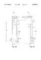
- FIGS. 1A and 1Bare plan and side view diagrams of an underground pipe and cable locator embodiment of the present invention (The terms “left” and “right” are arbitrary and are used here only in reference to FIGS. 1-4.);
- FIG. 2is a simplified schematic diagram of a locator similar to that shown in FIG. 1;
- FIG. 3is a schematic diagram of a PLL/clock/lock-detection subsystem useful in the locator embodiment of FIG. 1;
- FIG. 4is a schematic diagram of a dual-range channel processor useful in the locator embodiment of FIG. 1.
- FIGS. 1A and 1Billustrate an underground pipe and cable locator embodiment of the present invention, referred to herein by the general reference numeral 10.
- a separate transmitteris used to stimulate electromagnetic radiations from a buried pipe, cable, or other electrical conductor. Such electromagnetic radiations can then be tracked above ground by the locator 10.
- the locator 10comprises a lightweight plastic housing 12 that can be separated into front and back parts 14 and 16.
- the upper part of the housing 12includes a top receiver antenna (E T ) 18 boxed inside an electrostatic shield 20.
- the lower part of the housing 12includes a bottom receiver antenna (E B ) 22 boxed inside an electrostatic shield 24.
- a left wing part of the housing 12includes a left receiver antenna (E L ) 26.
- a right wing part of the housing 12includes a right receiver antenna (E R ) 28.
- the bottom edge of the housing 12includes a center receiver antenna (E C ) 30.
- a display head 32includes all the operating electronics, bubble-level, user display, and batteries.
- the top and bottom receiver antennas (E T ) 18 and (E B ) 22each comprised a 3.0 L ⁇ 0.330 D inch round ferrite rod with 480 turns of wire wound in segments to minimize capacitive coupling and maximize inductive-Q.
- the left and right receiver antennas (E L ) 26 and (E R ) 28each comprised a 1.06 L ⁇ 0.652 D inch round ferrite rod with 350 turns of wire also wound in segments to minimize capacitive coupling and maximize inductive-Q.
- the center receiver antenna (E C ) 30comprised three turns on a 0.5 inch square form.
- the electrostatic shields 20 and 24were constructed of carbon-painted surfaces inside the front and back parts 14 and 16 and connected to each other and signal ground by compression springs.
- the top and bottom receiver antennas (E T ) 18 and (E B ) 22were separated by a distance (D T-B ) of about 25.5 inches.
- the signal-center of the bottom receiver antenna (E B ) 22was located about one inch up from the bottom end of the housing 12.
- the signal-center of the center receiver antenna (E C ) 30was located about one-half inch from the bottom end of the housing 12.
- the locator 10is intended to be used with its bottom end plumb to its top end, as shown by the plumb-line in FIGS. 1A and 1B.
- the outside edges of each of the left receiver antenna (E L ) 26 and right receiver antenna (E R ) 28are preferably oriented with about a 1° tilt up from horizontal.
- the most accurate depth measurementsare obtained when the top and bottom receiver antennas (E T ) 18 and (E B ) 22 are within a few degrees of plumb to one another, and the bottom end of the housing 12 is resting on the surface of the ground.
- FIG. 2represents a simplified schematic diagram of the locator 10.
- the receiver antennas 18, 22, 26, 28 and 30are grouped into three identical continuous-duty analog channels 34, 36, and 38 for signal processing.
- the top analog channel 34includes the top receiver antenna (E T ) 18, a pre-amplifier 40 and 42, and a base and extended range synchronous full-wave rectifier-filters 44 and 46.
- the base and extended range synchronous full-wave rectifier-filtersalso function as phase detectors and can be referred to that way, e.g., as in FIG.
- the power level of the electromagnetic signal sensed by the top receiver antenna (E T ) 18is detected by a precise, near-zero-distortion conversion of the received AC signal to a DC value by the synchronous full-wave rectifier-filters 44 and 46.
- the left, right and center antennas (E L ) 26, (E R ) 28 and (E C ) 30are combined, as shown schematically, in analog channel 36 to produce one signal for a pair of pre-amplifiers 48 and 50, and a pair of base and extended range synchronous full-wave rectifier-filters 52 and 54.
- the bottom analog channel 38includes bottom receiver antenna (E B ) 22, a pair of pre-amplifiers 56 and 58, and a pair of base and extended range synchronous full-wave rectifier-filters 60 and 62.
- a phase-locked loop (PLL) 64is used to lock onto the signal received by the bottom receiver antenna (E B ) 22.
- the PLL 64provides an in-phase (0°) synchronous gating signal to each and all of the synchronous full-wave rectifier-filters 44, 46, 52, 54, 60, and 62.
- An analog LOCK signalis provided to a 20-bit binary analog-to-digital converter (ADC) 66, e.g., that will be within a particular range when the PLL 64 is actively tracking a signal.
- ADCbinary analog-to-digital converter
- a microprocessor (CPU) 68is connected to multiplex-in each of the signal inputs of the ADC 66.
- CPU 68is programmed to choose either a first range (range-1), e.g., inputs to ADC 66 from the synchronous full-wave rectifier-filters 44, 52, and 60; or a second range (range-2), e.g., inputs from the synchronous full-wave rectifier-filters 46, 54, and 62.
- An electrically-erasable programmable read-only memory (EEPROM) 70is used to store calibration information that removes the gain and offset mismatches that exist between the three continuous-duty analog channels 34, 36, and 38.
- a user display 72provides a bar-arrow readout that indicates a left-right direction to follow an underground pipe or cable, and a numeric readout that continuously provides a depth estimate. If an operator is walking along with the locator 10 off-plumb more than a few degrees and tracking a target conductor, an estimated depth reading will be presented. Also, if the bottom of locator 10 is not resting on the surface, the depth readings will be off two or three inches. But, this is an extremely useful mode as it provides assurances that the operator is following the conductor he intends to track, and this mode gives important real-time information about any sudden or gradual changes in the depth of the conductor that are often associated with proximity to other utility lines, across driveways, etc.
- a plumb sensor 74can either be a bubble-level type which only provides a visual indication for a user, or a mercury-switch type that can indicate to the CPU 68 when the locator 10 is plumb.
- the mercury-switch type of plumb sensor 74is preferred and is shown in FIG. 2.
- An on-off switch 78can be operated to supply power from a battery 80 to the locator 10.
- a control line from CPU 68is able to toggle power off, e.g., after a long period of inactivity to conserve battery life.
- a speaker 82is driven with a variety of audio tones, and/or synthesized voices, that are used to indicate to the user various operational conditions, e.g., off-left, off-right, centered, etc.
- the depth display 72automatically changes mode to indicate a higher accuracy measurement.
- Embodiments of the present inventionintegrate the location and depth readout functions so an operator can consider both together before making any final surface-marking decisions.
- a main loophas the ADC 66 continuously sample all of its multiplexed inputs including the PLL lock-range voltage and a battery-voltage sense line, and then outputs an estimate of the remaining battery capacity on the user display. An eight kHz trace mode can then commence. If the LOCK input to the ADC 66 is within a preferred range then the word "lock" is displayed on the user display 72.
- CPU 68chooses which input range to use for calculations depending on the pre-amplified and amplitude detected level for the bottom receiver antenna (E B ) 22. The left/right amplitude is calculated by a compression algorithm to give a left-right direction to the user on the user display 72.
- a first steady toneis output to the speaker 82, otherwise if the direction is to the right a different speaker frequency can be output.
- the depthis calculated by using a conventional depth equation, and the result is displayed.
- a suitable algorithm to calculate depthis described by the present inventor, Earl Peterman, in U.S. Pat. No. 4,520,317, issued May 28, 1985. Such patent is incorporated herein by reference.
- FIG. 3illustrates a PLL/clock/lock-detection subsystem 100.
- a synchronous quadrature full-wave rectifieris included which receives a non-inverted sample signal on an input 102 to an analog multiplexer 104, e.g., a part of a 74HC4053 or CD4053 triple 2-channel analog multiplexer-demultiplexer.
- a unity-gain analog inverter 106provides an inverted copy of the input 102 on an input 108.
- a gate control 110is timed to select the input 102 during the second 90° of its positive cycle and the first 90° of its negative cycle, and then switch to the input 108 to gate through the same two portions of the inverted copy for the last half of each gate control clock cycle.
- An output 112is thus zero when the input is exactly 90° offset from the gate control clock voltage 110. It rapidly develops a positive voltage if leading in phase or a negative voltage if it is lagging in phase.
- a resistor-capacitor filter combination 114 and 116sets a loop-response constant of about fifty Hz for a comparator 118 operating as a zero-crossing detector. For example, a type MC34181 can be used for comparator 118.
- a signal line 120will provide, e.g., an error signal that dithers up and down at approximately fifty Hz when the phase of the gate 110 is hovering about the phase of the inputs 102 and 108.
- a digital phase lock loop (PLL) 126is connected to a reference oscillator 128 and provides a tracking frequency "f" which drives a down-counter 130.
- the oscillator 128can be a type HA2210 with an 11.703880 MHz crystal.
- the PLL 126can be a type 74HC297, with an up-down control pin connected to signal line 120. The error voltage on the up-down pin modulates the internal variable ratio down-counter of the PLL 126, so that the output of counter 130 is equal to the operational frequency on input 102.
- Counter 130can be a 74HC74, programmed to act as a divide-by-four counter providing gate control (clock) output 110.
- resistor-capacitor filter combination 122 and 124provides a LOCK signal that is equivalent to that output by the PLL circuit 64 to ADC 66 in FIG. 2.
- a zero voltageindicates good lock conditions.
- Each of the synchronous full-wave rectifier and filters 44, 46, 52, 54, 60 and 62are preferably similar in design to rectifier 104 and filter combination 114 and 116 in the PLL subsystem 100, except that their gating signals are all taken from line 132 on counter 130. They are timed 90° ahead of the gating signal used to drive synchronous rectifier 104 in the PLL/clock/lock detection subsystem 100, and this operates with the gating waveform in phase with their input signals to produce maximum DC rectified outputs.
- FIG. 4represents a schematic diagram of a dual-range channel processor 150.
- Each pair of range-1 and range-2 rectifier-filters 44 & 46, 52 & 54, and 60 & 62, in FIG. 2,could be implemented with a dual-range channel processor 150.
- An antenna signal input 152such as from E T antenna 18, E C E L E R antenna array 30, 26 and 28 or E B antenna 22 in FIG. 2, is input to a first amplifier 154 with a gain of 10.00.
- a buffer amplifier 156provides a unity gain of 1.00.
- a precision analog inverter 158provides a gain of -1.00 and is chopper-stabilized by an op-amp 160 which ensures that any DC offset appearing on one input to multiplexer 162, will be exactly mirrored with opposite polarity on the other input for that channel.
- First range output 166will thus include no DC offset voltage from amplifiers 154, 156 and 158.
- An analog multiplexer 162is controlled by a gating signal input 164 to synchronously pass through only the half-cycle outputs of unity-gain amplifier 156 and the precision analog inverter 158.
- the combined outputis passed through as first range output 166 which is filtered by a resistor-capacitor combination 168 and 170.
- the first range rectified output 166is equivalent to that of filters 44, 52, and 60 in FIG. 2.
- a second channel with a higher gaincomprises a first amplifier 172 with an AC gain of 15.00 followed by a second amplifier 174 also with an AC gain of 15.00.
- a precision analog inverter 176provides a gain of -1.00.
- the analog multiplexer 162is also controlled by the gating signal input 164 to synchronously pass through only the half-cycle non-inverted output of amplifier 174 and the precision analog inverter 176.
- the combined outputis passed through as second range output 178 which is filtered by a resistor-capacitor combination 180 and 182.
- the second range output 178is equivalent to that of filters 46, 54, and 62 in FIG. 2.
- the precision analog inverter 176can also be chopper-stabilized by a circuit similar to that of op-amp 160, e.g., instead of having its non-inverting input simply tied to signal ground.
Landscapes
- Life Sciences & Earth Sciences (AREA)
- Engineering & Computer Science (AREA)
- Environmental & Geological Engineering (AREA)
- Geology (AREA)
- Remote Sensing (AREA)
- Physics & Mathematics (AREA)
- General Life Sciences & Earth Sciences (AREA)
- General Physics & Mathematics (AREA)
- Geophysics (AREA)
- Geophysics And Detection Of Objects (AREA)
Abstract
Description
Claims (11)
Priority Applications (1)
| Application Number | Priority Date | Filing Date | Title |
|---|---|---|---|
| US09/084,839US6140819A (en) | 1998-05-26 | 1998-05-26 | Continuous-depth-indicating underground pipe and cable locator |
Applications Claiming Priority (1)
| Application Number | Priority Date | Filing Date | Title |
|---|---|---|---|
| US09/084,839US6140819A (en) | 1998-05-26 | 1998-05-26 | Continuous-depth-indicating underground pipe and cable locator |
Publications (1)
| Publication Number | Publication Date |
|---|---|
| US6140819Atrue US6140819A (en) | 2000-10-31 |
Family
ID=22187544
Family Applications (1)
| Application Number | Title | Priority Date | Filing Date |
|---|---|---|---|
| US09/084,839Expired - LifetimeUS6140819A (en) | 1998-05-26 | 1998-05-26 | Continuous-depth-indicating underground pipe and cable locator |
Country Status (1)
| Country | Link |
|---|---|
| US (1) | US6140819A (en) |
Cited By (56)
| Publication number | Priority date | Publication date | Assignee | Title |
|---|---|---|---|---|
| US6392554B1 (en)* | 2000-09-16 | 2002-05-21 | Beom Jae Lee | Electromagnetic wave isolation apparatus for use in multi-outlets |
| US6529006B1 (en) | 2001-10-31 | 2003-03-04 | Paul Hayes | Method and apparatus for resolving the position and identity of buried conductive bodies |
| USD472164S1 (en) | 2002-06-11 | 2003-03-25 | Dave Newton | Magnetic stud detector |
| US20030058961A1 (en)* | 2001-08-01 | 2003-03-27 | Radiodetection Limited | Method and system for recovering information from a magnetic field signal usable for locating an underground object |
| US6617856B1 (en)* | 2002-02-15 | 2003-09-09 | Radiodetection Limited | Electronic marker locator system and method |
| US20040070535A1 (en)* | 2002-10-09 | 2004-04-15 | Olsson Mark S. | Single and multi-trace omnidirectional sonde and line locators and transmitter used therewith |
| US20040070399A1 (en)* | 2002-10-09 | 2004-04-15 | Olsson Mark S. | Omnidirectional sonde and line locator |
| WO2003069769A3 (en)* | 2002-02-15 | 2004-04-29 | Radiodetection Ltd | Digital phase-quadrature oscillator |
| WO2005015263A1 (en)* | 2003-07-18 | 2005-02-17 | Metrotech Corporation | Method and apparatus for digital detection of electromagnetic signal strength and signal direction in metallic pipes and cables |
| US20050156776A1 (en)* | 2003-11-25 | 2005-07-21 | Waite James W. | Centerline and depth locating method for non-metallic buried utility lines |
| US20060036376A1 (en)* | 2004-07-29 | 2006-02-16 | Thorkell Gudmundsson | Precise location of buried metallic pipes and cables in the presence of signal distortion |
| US20060055584A1 (en)* | 2003-11-25 | 2006-03-16 | Waite James W | Sensor fusion for model-based detection in pipe and cable locator systems |
| WO2006015310A3 (en)* | 2004-07-29 | 2006-04-20 | Metrotech Corp Inc | Sensor fusion for model-based detection in pipe and cable locator systems |
| US20070150201A1 (en)* | 2001-12-07 | 2007-06-28 | Terje Eidesmo | Electromagnetic surveying for hydrocarbon reservoirs |
| US20070288195A1 (en)* | 2006-03-10 | 2007-12-13 | Waite James W | Long line monitoring and locating system |
| US7640105B2 (en) | 2007-03-13 | 2009-12-29 | Certus View Technologies, LLC | Marking system and method with location and/or time tracking |
| US20100074698A1 (en)* | 2008-09-25 | 2010-03-25 | Terra Shield, Llc | Sheet pile for the subterranean support of underground conduits |
| US20100263892A1 (en)* | 2009-04-16 | 2010-10-21 | Hercules Machinery Corporation | Method and apparatus for facilitating the subterranean support of underground conduits having a fixed insertion axis |
| US20100330542A1 (en)* | 2009-06-25 | 2010-12-30 | Certusview Technologies, Llc | Systems for and methods of simulating facilities for use in locate operations training exercises |
| US20110008111A1 (en)* | 2009-07-10 | 2011-01-13 | Hercules Machinery Corporation | Apparatus for inserting sheet pile having an independently adjustable insertion axis and method for using the same |
| US20110012600A1 (en)* | 2009-07-14 | 2011-01-20 | Connor Martin C | Electromagnetic antenna and method of use for detecting objects |
| USD634657S1 (en) | 2010-03-01 | 2011-03-22 | Certusview Technologies, Llc | Paint holder of a marking device |
| USD634655S1 (en) | 2010-03-01 | 2011-03-22 | Certusview Technologies, Llc | Handle of a marking device |
| USD634656S1 (en) | 2010-03-01 | 2011-03-22 | Certusview Technologies, Llc | Shaft of a marking device |
| USD643321S1 (en) | 2010-03-01 | 2011-08-16 | Certusview Technologies, Llc | Marking device |
| US8060304B2 (en) | 2007-04-04 | 2011-11-15 | Certusview Technologies, Llc | Marking system and method |
| US8086426B2 (en) | 2004-01-09 | 2011-12-27 | Statoil Asa | Processing seismic data representing a physical system |
| US20120006116A1 (en)* | 2010-06-10 | 2012-01-12 | Hwang Tae-Joon | Device, System and Method For Locating a Pipe |
| US20120043960A1 (en)* | 2010-08-17 | 2012-02-23 | Operations Technology Development, Nfp | Non-intrusive detection of live electrical lines |
| US8188748B2 (en) | 2006-02-09 | 2012-05-29 | Electromagnetic Geoservices As | Electromagnetic surveying |
| US8228066B2 (en) | 2006-06-09 | 2012-07-24 | Electromagnetic Geoservices As | Instrument for measuring electromagnetic signals |
| US8280631B2 (en) | 2008-10-02 | 2012-10-02 | Certusview Technologies, Llc | Methods and apparatus for generating an electronic record of a marking operation based on marking device actuations |
| US8311765B2 (en) | 2009-08-11 | 2012-11-13 | Certusview Technologies, Llc | Locating equipment communicatively coupled to or equipped with a mobile/portable device |
| US8315804B2 (en) | 2007-01-09 | 2012-11-20 | Statoilhydro Asa | Method of and apparatus for analyzing data from an electromagnetic survey |
| US8400155B2 (en) | 2008-10-02 | 2013-03-19 | Certusview Technologies, Llc | Methods and apparatus for displaying an electronic rendering of a locate operation based on an electronic record of locate information |
| US8442766B2 (en) | 2008-10-02 | 2013-05-14 | Certusview Technologies, Llc | Marking apparatus having enhanced features for underground facility marking operations, and associated methods and systems |
| USD684067S1 (en) | 2012-02-15 | 2013-06-11 | Certusview Technologies, Llc | Modular marking device |
| US8473209B2 (en) | 2007-03-13 | 2013-06-25 | Certusview Technologies, Llc | Marking apparatus and marking methods using marking dispenser with machine-readable ID mechanism |
| US8478523B2 (en) | 2007-03-13 | 2013-07-02 | Certusview Technologies, Llc | Marking apparatus and methods for creating an electronic record of marking apparatus operations |
| US20130200901A1 (en)* | 2011-08-08 | 2013-08-08 | Seektech, Inc. | Phase synchronized buried object locator apparatus, systems, and methods |
| US20130293233A1 (en)* | 2007-09-28 | 2013-11-07 | The Charles Machine Works, Inc. | Method For Guiding A Downhole Tool Assembly Using An Above-Ground Receiver System |
| DE102012210009A1 (en)* | 2012-06-14 | 2013-12-19 | Robert Bosch Gmbh | Hand tool device |
| US8620572B2 (en) | 2009-08-20 | 2013-12-31 | Certusview Technologies, Llc | Marking device with transmitter for triangulating location during locate operations |
| US8620616B2 (en) | 2009-08-20 | 2013-12-31 | Certusview Technologies, Llc | Methods and apparatus for assessing marking operations based on acceleration information |
| US8626571B2 (en) | 2009-02-11 | 2014-01-07 | Certusview Technologies, Llc | Management system, and associated methods and apparatus, for dispatching tickets, receiving field information, and performing a quality assessment for underground facility locate and/or marking operations |
| US8913463B2 (en) | 2006-10-12 | 2014-12-16 | Electromagnetic Geoservices Asa | Positioning system |
| US8965700B2 (en) | 2008-10-02 | 2015-02-24 | Certusview Technologies, Llc | Methods and apparatus for generating an electronic record of environmental landmarks based on marking device actuations |
| US9097522B2 (en) | 2009-08-20 | 2015-08-04 | Certusview Technologies, Llc | Methods and marking devices with mechanisms for indicating and/or detecting marking material color |
| EP1478950B1 (en)* | 2002-02-21 | 2016-08-24 | Robert Bosch Gmbh | Measuring appliance comprising integrated operating instructions |
| WO2017001099A1 (en)* | 2015-06-30 | 2017-01-05 | Robert Bosch Gmbh | Locating device |
| US10024994B1 (en)* | 2006-07-18 | 2018-07-17 | SeeScan, Inc. | Wearable magnetic field utility locator system with sound field generation |
| US10042074B2 (en) | 2014-06-05 | 2018-08-07 | The Charles Machine Works, Inc. | Underground utility line locator and method for use |
| US10725191B2 (en) | 2016-06-09 | 2020-07-28 | Optimal Ranging, Inc. | Method and apparatus for simultaneous inductive excitation and locating of utilities |
| CN111707876A (en)* | 2020-06-29 | 2020-09-25 | 中国电子科技集团公司第十四研究所 | A Two-axis Verticality Quick Adjustment Mechanism for Large Antenna Near Field Tester |
| US10809410B2 (en) | 2016-06-09 | 2020-10-20 | Optimal Ranging, Inc. | Method and apparatus for simultaneous inductive excitation and locating of utilities |
| EP4571328A1 (en)* | 2023-12-15 | 2025-06-18 | Yongzhou Noyafa Electronic Co., Ltd. | Underground cable path tester |
Citations (24)
| Publication number | Priority date | Publication date | Assignee | Title |
|---|---|---|---|---|
| US2501598A (en)* | 1947-07-28 | 1950-03-21 | Shell Dev | Magnetic method of pipe-line inspection |
| US3471772A (en)* | 1967-05-02 | 1969-10-07 | Singer Inc H R B | Instrument for measuring the range and approximate size of buried or hidden metal objects |
| US3617865A (en)* | 1968-05-25 | 1971-11-02 | Goroku Hakata | Method and apparatus for locating a buried metallic line employing magnetic field gradient measurements |
| SU389482A1 (en)* | 1971-07-15 | 1973-07-05 | Б. И. Блажкевич, В. Ю. Воробкевич , Е. В. Ярошевский Физико механический институт Украинской ССР | METHOD FOR DETERMINING DISTANCE BEFORE WIRES FLOWED BY AC VARIABLE |
| FR2239008A1 (en)* | 1973-07-23 | 1975-02-21 | Citroen Sa | |
| US3893025A (en)* | 1974-02-01 | 1975-07-01 | Plosser George G | Apparatus for determining the distance to a concealed conductive structure |
| US3967282A (en)* | 1974-01-30 | 1976-06-29 | The Ohio State University | Underground pipe detector |
| US3991363A (en)* | 1975-08-11 | 1976-11-09 | Bell Telephone Laboratories, Incorporated | Method and apparatus for detecting faults in buried insulated conductors |
| JPS5281979A (en)* | 1975-12-29 | 1977-07-08 | Anima Corp | Centroid rocking planimeter |
| GB1509914A (en)* | 1975-05-23 | 1978-05-04 | Electrolocation Ltd | Detector systems for electromagnetic surveying |
| US4091322A (en)* | 1976-05-24 | 1978-05-23 | Societe Intersub Developpement | Eddy current generating type metal pipeline detector |
| US4103791A (en)* | 1977-06-03 | 1978-08-01 | Harnischfeger Corporation | Shovel attachment means for hydraulic excavator |
| US4134061A (en)* | 1977-02-02 | 1979-01-09 | Gudgel Howard S | Pipe current detector with plural magnetic flux detectors |
| GB2006438A (en)* | 1977-08-02 | 1979-05-02 | Electricity Council | Apparatus for Locating Electric Conductors |
| US4220913A (en)* | 1978-05-23 | 1980-09-02 | Electrolocation Limited | Apparatus for and methods of electromagnetic surveying of elongated underground conductors |
| US4249630A (en)* | 1978-10-31 | 1981-02-10 | Northern Telecom Limited | Plow guidance system |
| US4295095A (en)* | 1979-01-29 | 1981-10-13 | British Gas Corporation | Apparatus and method for detecting the location of metallic objects having alternating current passing therethrough |
| US4387340A (en)* | 1980-07-31 | 1983-06-07 | Metrotech, Inc. | Apparatus for determining the distance to a concealed conductive object which is radiating an alternating current signal |
| US4520317A (en)* | 1980-07-31 | 1985-05-28 | Metrotech, Inc. | Apparatus including a pair of automatic gain controlled amplifiers for determining the lateral direction to a concealed conductive object |
| US4691165A (en)* | 1982-07-09 | 1987-09-01 | Laszlo Szedlmajer | Method and apparatus including spaced antennas for determining the trace and depth of underground metallic conductors |
| US5001430A (en)* | 1989-06-05 | 1991-03-19 | Heath Consultants, Inc. | Apparatus for locating concealed electrical conductors |
| US5093622A (en)* | 1989-03-17 | 1992-03-03 | Minnesota Mining And Manufacturing Company | Method and apparatus for determining direction to and position of an underground conductor |
| US5194812A (en)* | 1991-05-16 | 1993-03-16 | Yokoi Manufacturing Co., Ltd. | Device for determining depth and direction of buried objects |
| US5640092A (en)* | 1990-09-27 | 1997-06-17 | Motazed; Behnam | Electromagnetic pipe mapper for accurate location and depth determination |
- 1998
- 1998-05-26USUS09/084,839patent/US6140819A/ennot_activeExpired - Lifetime
Patent Citations (24)
| Publication number | Priority date | Publication date | Assignee | Title |
|---|---|---|---|---|
| US2501598A (en)* | 1947-07-28 | 1950-03-21 | Shell Dev | Magnetic method of pipe-line inspection |
| US3471772A (en)* | 1967-05-02 | 1969-10-07 | Singer Inc H R B | Instrument for measuring the range and approximate size of buried or hidden metal objects |
| US3617865A (en)* | 1968-05-25 | 1971-11-02 | Goroku Hakata | Method and apparatus for locating a buried metallic line employing magnetic field gradient measurements |
| SU389482A1 (en)* | 1971-07-15 | 1973-07-05 | Б. И. Блажкевич, В. Ю. Воробкевич , Е. В. Ярошевский Физико механический институт Украинской ССР | METHOD FOR DETERMINING DISTANCE BEFORE WIRES FLOWED BY AC VARIABLE |
| FR2239008A1 (en)* | 1973-07-23 | 1975-02-21 | Citroen Sa | |
| US3967282A (en)* | 1974-01-30 | 1976-06-29 | The Ohio State University | Underground pipe detector |
| US3893025A (en)* | 1974-02-01 | 1975-07-01 | Plosser George G | Apparatus for determining the distance to a concealed conductive structure |
| GB1509914A (en)* | 1975-05-23 | 1978-05-04 | Electrolocation Ltd | Detector systems for electromagnetic surveying |
| US3991363A (en)* | 1975-08-11 | 1976-11-09 | Bell Telephone Laboratories, Incorporated | Method and apparatus for detecting faults in buried insulated conductors |
| JPS5281979A (en)* | 1975-12-29 | 1977-07-08 | Anima Corp | Centroid rocking planimeter |
| US4091322A (en)* | 1976-05-24 | 1978-05-23 | Societe Intersub Developpement | Eddy current generating type metal pipeline detector |
| US4134061A (en)* | 1977-02-02 | 1979-01-09 | Gudgel Howard S | Pipe current detector with plural magnetic flux detectors |
| US4103791A (en)* | 1977-06-03 | 1978-08-01 | Harnischfeger Corporation | Shovel attachment means for hydraulic excavator |
| GB2006438A (en)* | 1977-08-02 | 1979-05-02 | Electricity Council | Apparatus for Locating Electric Conductors |
| US4220913A (en)* | 1978-05-23 | 1980-09-02 | Electrolocation Limited | Apparatus for and methods of electromagnetic surveying of elongated underground conductors |
| US4249630A (en)* | 1978-10-31 | 1981-02-10 | Northern Telecom Limited | Plow guidance system |
| US4295095A (en)* | 1979-01-29 | 1981-10-13 | British Gas Corporation | Apparatus and method for detecting the location of metallic objects having alternating current passing therethrough |
| US4387340A (en)* | 1980-07-31 | 1983-06-07 | Metrotech, Inc. | Apparatus for determining the distance to a concealed conductive object which is radiating an alternating current signal |
| US4520317A (en)* | 1980-07-31 | 1985-05-28 | Metrotech, Inc. | Apparatus including a pair of automatic gain controlled amplifiers for determining the lateral direction to a concealed conductive object |
| US4691165A (en)* | 1982-07-09 | 1987-09-01 | Laszlo Szedlmajer | Method and apparatus including spaced antennas for determining the trace and depth of underground metallic conductors |
| US5093622A (en)* | 1989-03-17 | 1992-03-03 | Minnesota Mining And Manufacturing Company | Method and apparatus for determining direction to and position of an underground conductor |
| US5001430A (en)* | 1989-06-05 | 1991-03-19 | Heath Consultants, Inc. | Apparatus for locating concealed electrical conductors |
| US5640092A (en)* | 1990-09-27 | 1997-06-17 | Motazed; Behnam | Electromagnetic pipe mapper for accurate location and depth determination |
| US5194812A (en)* | 1991-05-16 | 1993-03-16 | Yokoi Manufacturing Co., Ltd. | Device for determining depth and direction of buried objects |
Cited By (105)
| Publication number | Priority date | Publication date | Assignee | Title |
|---|---|---|---|---|
| US6392554B1 (en)* | 2000-09-16 | 2002-05-21 | Beom Jae Lee | Electromagnetic wave isolation apparatus for use in multi-outlets |
| US20030058961A1 (en)* | 2001-08-01 | 2003-03-27 | Radiodetection Limited | Method and system for recovering information from a magnetic field signal usable for locating an underground object |
| WO2003012478A3 (en)* | 2001-08-01 | 2003-09-25 | Radiodetection Ltd | System for recovering information from a magnetic field signal usable for locating an underground object and method |
| US7079591B2 (en) | 2001-08-01 | 2006-07-18 | Radiodetection Limited | Method and system for recovering information from a magnetic field signal usable for locating an underground object |
| US6529006B1 (en) | 2001-10-31 | 2003-03-04 | Paul Hayes | Method and apparatus for resolving the position and identity of buried conductive bodies |
| US20070150201A1 (en)* | 2001-12-07 | 2007-06-28 | Terje Eidesmo | Electromagnetic surveying for hydrocarbon reservoirs |
| WO2003069769A3 (en)* | 2002-02-15 | 2004-04-29 | Radiodetection Ltd | Digital phase-quadrature oscillator |
| US6617856B1 (en)* | 2002-02-15 | 2003-09-09 | Radiodetection Limited | Electronic marker locator system and method |
| EP1478950B1 (en)* | 2002-02-21 | 2016-08-24 | Robert Bosch Gmbh | Measuring appliance comprising integrated operating instructions |
| USD472164S1 (en) | 2002-06-11 | 2003-03-25 | Dave Newton | Magnetic stud detector |
| US7498816B1 (en) | 2002-10-09 | 2009-03-03 | Seektech, Inc. | Omnidirectional sonde and line locator |
| US20040070399A1 (en)* | 2002-10-09 | 2004-04-15 | Olsson Mark S. | Omnidirectional sonde and line locator |
| US8035390B2 (en) | 2002-10-09 | 2011-10-11 | Seektech, Inc. | Omnidirectional sonde and line locator |
| US7009399B2 (en) | 2002-10-09 | 2006-03-07 | Deepsea Power & Light | Omnidirectional sonde and line locator |
| US20110037472A1 (en)* | 2002-10-09 | 2011-02-17 | Seektech, Inc. | Omnidirectional Sonde and Line Locator |
| US20040070535A1 (en)* | 2002-10-09 | 2004-04-15 | Olsson Mark S. | Single and multi-trace omnidirectional sonde and line locators and transmitter used therewith |
| US9696447B1 (en) | 2002-10-09 | 2017-07-04 | SeeScan, Inc. | Buried object locating methods and apparatus using multiple electromagnetic signals |
| US9989662B1 (en) | 2002-10-09 | 2018-06-05 | SeeScan, Inc. | Buried object locating device with a plurality of spherical sensor balls that include a plurality of orthogonal antennae |
| US20190137644A1 (en)* | 2002-10-09 | 2019-05-09 | SeeScan, Inc. | Buried object locating devices and methods |
| WO2005015263A1 (en)* | 2003-07-18 | 2005-02-17 | Metrotech Corporation | Method and apparatus for digital detection of electromagnetic signal strength and signal direction in metallic pipes and cables |
| US7062414B2 (en)* | 2003-07-18 | 2006-06-13 | Metrotech Corporation | Method and apparatus for digital detection of electromagnetic signal strength and signal direction in metallic pipes and cables |
| US20050096879A1 (en)* | 2003-07-18 | 2005-05-05 | Waite James W. | Method and apparatus for digital detection of electromagnetic signal strength and signal direction in metallic pipes and cables |
| CN100373171C (en)* | 2003-07-18 | 2008-03-05 | 麦特罗特克公司 | Method and apparatus for digital detection of electromagnetic signal strength and signal direction |
| US20050156776A1 (en)* | 2003-11-25 | 2005-07-21 | Waite James W. | Centerline and depth locating method for non-metallic buried utility lines |
| US7113124B2 (en) | 2003-11-25 | 2006-09-26 | Metrotech Corporation, Inc. | Centerline and depth locating method for non-metallic buried utility lines |
| US7834801B2 (en) | 2003-11-25 | 2010-11-16 | Metrotech Corporation, Inc. | Sensor fusion for model-based detection in pipe and cable locator systems |
| US20060055584A1 (en)* | 2003-11-25 | 2006-03-16 | Waite James W | Sensor fusion for model-based detection in pipe and cable locator systems |
| US8086426B2 (en) | 2004-01-09 | 2011-12-27 | Statoil Asa | Processing seismic data representing a physical system |
| US7356421B2 (en)* | 2004-07-29 | 2008-04-08 | Metrotech Corporation, Inc. | Precise location of buried metallic pipes and cables in the presence of signal distortion |
| US20060036376A1 (en)* | 2004-07-29 | 2006-02-16 | Thorkell Gudmundsson | Precise location of buried metallic pipes and cables in the presence of signal distortion |
| WO2006015310A3 (en)* | 2004-07-29 | 2006-04-20 | Metrotech Corp Inc | Sensor fusion for model-based detection in pipe and cable locator systems |
| US8188748B2 (en) | 2006-02-09 | 2012-05-29 | Electromagnetic Geoservices As | Electromagnetic surveying |
| US20070288195A1 (en)* | 2006-03-10 | 2007-12-13 | Waite James W | Long line monitoring and locating system |
| US8228066B2 (en) | 2006-06-09 | 2012-07-24 | Electromagnetic Geoservices As | Instrument for measuring electromagnetic signals |
| US10024994B1 (en)* | 2006-07-18 | 2018-07-17 | SeeScan, Inc. | Wearable magnetic field utility locator system with sound field generation |
| US8913463B2 (en) | 2006-10-12 | 2014-12-16 | Electromagnetic Geoservices Asa | Positioning system |
| US8315804B2 (en) | 2007-01-09 | 2012-11-20 | Statoilhydro Asa | Method of and apparatus for analyzing data from an electromagnetic survey |
| US8775077B2 (en) | 2007-03-13 | 2014-07-08 | Certusview Technologies, Llc | Systems and methods for using location data to electronically display dispensing of markers by a marking system or marking tool |
| US7640105B2 (en) | 2007-03-13 | 2009-12-29 | Certus View Technologies, LLC | Marking system and method with location and/or time tracking |
| US8478523B2 (en) | 2007-03-13 | 2013-07-02 | Certusview Technologies, Llc | Marking apparatus and methods for creating an electronic record of marking apparatus operations |
| US8473209B2 (en) | 2007-03-13 | 2013-06-25 | Certusview Technologies, Llc | Marking apparatus and marking methods using marking dispenser with machine-readable ID mechanism |
| US8700325B2 (en) | 2007-03-13 | 2014-04-15 | Certusview Technologies, Llc | Marking apparatus and methods for creating an electronic record of marking operations |
| US9086277B2 (en) | 2007-03-13 | 2015-07-21 | Certusview Technologies, Llc | Electronically controlled marking apparatus and methods |
| US8407001B2 (en) | 2007-03-13 | 2013-03-26 | Certusview Technologies, Llc | Systems and methods for using location data to electronically display dispensing of markers by a marking system or marking tool |
| US8903643B2 (en) | 2007-03-13 | 2014-12-02 | Certusview Technologies, Llc | Hand-held marking apparatus with location tracking system and methods for logging geographic location of same |
| US8401791B2 (en) | 2007-03-13 | 2013-03-19 | Certusview Technologies, Llc | Methods for evaluating operation of marking apparatus |
| US8386178B2 (en) | 2007-04-04 | 2013-02-26 | Certusview Technologies, Llc | Marking system and method |
| US8374789B2 (en) | 2007-04-04 | 2013-02-12 | Certusview Technologies, Llc | Systems and methods for using marking information to electronically display dispensing of markers by a marking system or marking tool |
| US8060304B2 (en) | 2007-04-04 | 2011-11-15 | Certusview Technologies, Llc | Marking system and method |
| US20130293233A1 (en)* | 2007-09-28 | 2013-11-07 | The Charles Machine Works, Inc. | Method For Guiding A Downhole Tool Assembly Using An Above-Ground Receiver System |
| US9146286B2 (en)* | 2007-09-28 | 2015-09-29 | The Charles Machine Works, Inc. | Receiver system for guiding a downhole tool assembly |
| US8303217B2 (en) | 2008-09-25 | 2012-11-06 | Terra Technologies, LLC | Systems for the subterranean support of underground conduits |
| US20100296872A1 (en)* | 2008-09-25 | 2010-11-25 | Terra Shield, Llc | Method and installation for the subterranean support of underground conduits |
| US8016518B2 (en) | 2008-09-25 | 2011-09-13 | Terra Technologies, LLC | Sheet pile for the subterranean support of underground conduits |
| US20100074698A1 (en)* | 2008-09-25 | 2010-03-25 | Terra Shield, Llc | Sheet pile for the subterranean support of underground conduits |
| US20100074690A1 (en)* | 2008-09-25 | 2010-03-25 | Terra Shield, Llc | Systems for the subterranean support of underground conduits |
| US8061934B2 (en) | 2008-09-25 | 2011-11-22 | Terra Technologies, LLC | Method and installation for the subterranean support of underground conduits |
| US20100074694A1 (en)* | 2008-09-25 | 2010-03-25 | Terra Shield, Llc | Methods for the subterranean support of underground conduits |
| US7771140B2 (en) | 2008-09-25 | 2010-08-10 | Terra Shield, Llc | Methods for the subterranean support of underground conduits |
| US8770140B2 (en) | 2008-10-02 | 2014-07-08 | Certusview Technologies, Llc | Marking apparatus having environmental sensors and operations sensors for underground facility marking operations, and associated methods and systems |
| US8478525B2 (en) | 2008-10-02 | 2013-07-02 | Certusview Technologies, Llc | Methods, apparatus, and systems for analyzing use of a marking device by a technician to perform an underground facility marking operation |
| US8361543B2 (en) | 2008-10-02 | 2013-01-29 | Certusview Technologies, Llc | Methods and apparatus for displaying an electronic rendering of a marking operation based on an electronic record of marking information |
| US8442766B2 (en) | 2008-10-02 | 2013-05-14 | Certusview Technologies, Llc | Marking apparatus having enhanced features for underground facility marking operations, and associated methods and systems |
| US8457893B2 (en) | 2008-10-02 | 2013-06-04 | Certusview Technologies, Llc | Methods and apparatus for generating an electronic record of a marking operation including service-related information and/or ticket information |
| US8731830B2 (en) | 2008-10-02 | 2014-05-20 | Certusview Technologies, Llc | Marking apparatus for receiving environmental information regarding underground facility marking operations, and associated methods and systems |
| US9542863B2 (en) | 2008-10-02 | 2017-01-10 | Certusview Technologies, Llc | Methods and apparatus for generating output data streams relating to underground utility marking operations |
| US8467969B2 (en) | 2008-10-02 | 2013-06-18 | Certusview Technologies, Llc | Marking apparatus having operational sensors for underground facility marking operations, and associated methods and systems |
| US8612148B2 (en) | 2008-10-02 | 2013-12-17 | Certusview Technologies, Llc | Marking apparatus configured to detect out-of-tolerance conditions in connection with underground facility marking operations, and associated methods and systems |
| US8280631B2 (en) | 2008-10-02 | 2012-10-02 | Certusview Technologies, Llc | Methods and apparatus for generating an electronic record of a marking operation based on marking device actuations |
| US8478524B2 (en) | 2008-10-02 | 2013-07-02 | Certusview Technologies, Llc | Methods and apparatus for dispensing marking material in connection with underground facility marking operations based on environmental information and/or operational information |
| US8965700B2 (en) | 2008-10-02 | 2015-02-24 | Certusview Technologies, Llc | Methods and apparatus for generating an electronic record of environmental landmarks based on marking device actuations |
| US8400155B2 (en) | 2008-10-02 | 2013-03-19 | Certusview Technologies, Llc | Methods and apparatus for displaying an electronic rendering of a locate operation based on an electronic record of locate information |
| US8731999B2 (en) | 2009-02-11 | 2014-05-20 | Certusview Technologies, Llc | Management system, and associated methods and apparatus, for providing improved visibility, quality control and audit capability for underground facility locate and/or marking operations |
| US8626571B2 (en) | 2009-02-11 | 2014-01-07 | Certusview Technologies, Llc | Management system, and associated methods and apparatus, for dispatching tickets, receiving field information, and performing a quality assessment for underground facility locate and/or marking operations |
| US9185176B2 (en) | 2009-02-11 | 2015-11-10 | Certusview Technologies, Llc | Methods and apparatus for managing locate and/or marking operations |
| US20100263892A1 (en)* | 2009-04-16 | 2010-10-21 | Hercules Machinery Corporation | Method and apparatus for facilitating the subterranean support of underground conduits having a fixed insertion axis |
| US8342778B2 (en) | 2009-04-16 | 2013-01-01 | Hercules Machinery Corporation | Method and apparatus for facilitating the subterranean support of underground conduits having a fixed insertion axis |
| US8585410B2 (en)* | 2009-06-25 | 2013-11-19 | Certusview Technologies, Llc | Systems for and methods of simulating facilities for use in locate operations training exercises |
| US20100330542A1 (en)* | 2009-06-25 | 2010-12-30 | Certusview Technologies, Llc | Systems for and methods of simulating facilities for use in locate operations training exercises |
| US8096733B2 (en) | 2009-07-10 | 2012-01-17 | Hercules Machinery Corporation | Apparatus for inserting sheet pile having an independently adjustable insertion axis and method for using the same |
| US20110008111A1 (en)* | 2009-07-10 | 2011-01-13 | Hercules Machinery Corporation | Apparatus for inserting sheet pile having an independently adjustable insertion axis and method for using the same |
| US20110012600A1 (en)* | 2009-07-14 | 2011-01-20 | Connor Martin C | Electromagnetic antenna and method of use for detecting objects |
| US8311765B2 (en) | 2009-08-11 | 2012-11-13 | Certusview Technologies, Llc | Locating equipment communicatively coupled to or equipped with a mobile/portable device |
| US8620616B2 (en) | 2009-08-20 | 2013-12-31 | Certusview Technologies, Llc | Methods and apparatus for assessing marking operations based on acceleration information |
| US9097522B2 (en) | 2009-08-20 | 2015-08-04 | Certusview Technologies, Llc | Methods and marking devices with mechanisms for indicating and/or detecting marking material color |
| US8620572B2 (en) | 2009-08-20 | 2013-12-31 | Certusview Technologies, Llc | Marking device with transmitter for triangulating location during locate operations |
| USD634657S1 (en) | 2010-03-01 | 2011-03-22 | Certusview Technologies, Llc | Paint holder of a marking device |
| USD634656S1 (en) | 2010-03-01 | 2011-03-22 | Certusview Technologies, Llc | Shaft of a marking device |
| USD634655S1 (en) | 2010-03-01 | 2011-03-22 | Certusview Technologies, Llc | Handle of a marking device |
| USD643321S1 (en) | 2010-03-01 | 2011-08-16 | Certusview Technologies, Llc | Marking device |
| US20120006116A1 (en)* | 2010-06-10 | 2012-01-12 | Hwang Tae-Joon | Device, System and Method For Locating a Pipe |
| US8674678B2 (en)* | 2010-06-10 | 2014-03-18 | Enbridge Gas Distribution Inc. | Device, system and method for locating a pipe |
| US8358120B2 (en)* | 2010-08-17 | 2013-01-22 | Operations Technology Development, Nfp | Non-intrusive detection of live electrical lines |
| US20120043960A1 (en)* | 2010-08-17 | 2012-02-23 | Operations Technology Development, Nfp | Non-intrusive detection of live electrical lines |
| US9435907B2 (en)* | 2011-08-08 | 2016-09-06 | SeeScan, Inc. | Phase synchronized buried object locator apparatus, systems, and methods |
| US20130200901A1 (en)* | 2011-08-08 | 2013-08-08 | Seektech, Inc. | Phase synchronized buried object locator apparatus, systems, and methods |
| USD684067S1 (en) | 2012-02-15 | 2013-06-11 | Certusview Technologies, Llc | Modular marking device |
| DE102012210009A1 (en)* | 2012-06-14 | 2013-12-19 | Robert Bosch Gmbh | Hand tool device |
| US10042074B2 (en) | 2014-06-05 | 2018-08-07 | The Charles Machine Works, Inc. | Underground utility line locator and method for use |
| WO2017001099A1 (en)* | 2015-06-30 | 2017-01-05 | Robert Bosch Gmbh | Locating device |
| US10725191B2 (en) | 2016-06-09 | 2020-07-28 | Optimal Ranging, Inc. | Method and apparatus for simultaneous inductive excitation and locating of utilities |
| US10809410B2 (en) | 2016-06-09 | 2020-10-20 | Optimal Ranging, Inc. | Method and apparatus for simultaneous inductive excitation and locating of utilities |
| CN111707876A (en)* | 2020-06-29 | 2020-09-25 | 中国电子科技集团公司第十四研究所 | A Two-axis Verticality Quick Adjustment Mechanism for Large Antenna Near Field Tester |
| CN111707876B (en)* | 2020-06-29 | 2023-03-28 | 中国电子科技集团公司第十四研究所 | A diaxon straightness quick adjustment mechanism that hangs down for large-scale antenna near field tester |
| EP4571328A1 (en)* | 2023-12-15 | 2025-06-18 | Yongzhou Noyafa Electronic Co., Ltd. | Underground cable path tester |
Similar Documents
| Publication | Publication Date | Title |
|---|---|---|
| US6140819A (en) | Continuous-depth-indicating underground pipe and cable locator | |
| CN101243334B (en) | Detectors for detecting buried current-carrying conductors | |
| US7605590B2 (en) | Digital locating system and device for underground object detection | |
| EP2098890B1 (en) | Detector for calculating the depth of a buried conductor | |
| US4639674A (en) | Apparatus and method employing extraneous field compensation for locating current-carrying objects | |
| US7755360B1 (en) | Portable locator system with jamming reduction | |
| US7057383B2 (en) | Method for decoupling interference due to bleedover in metallic pipe and cable locators | |
| CA2612877C (en) | A radio mode selectivity block for a detector for detecting a buried current carrying conductor | |
| CA2025088A1 (en) | Device for locating a boring machine | |
| EP2098888B1 (en) | A detector for calculating the distortion of an electromagnetic field produced by a buried current carrying conductor | |
| CA2656677C (en) | A detector for calculating a depth of a buried conductor | |
| DK160375B (en) | DEVICE FOR DETERMINING THE DISTANCE TO A HIDDEN CONDUCTIVE ITEM | |
| JP2008544272A (en) | Method and apparatus for detecting a current carrying conductor | |
| JPS5829875B2 (en) | Cable search method | |
| CN108362372A (en) | Low frequency noise measurement system | |
| RU2202812C1 (en) | Facility to search for underground pipe-lines | |
| RU12262U1 (en) | DEVICE FOR CONTINUOUS ELECTRIC PROFILING | |
| CN120386001A (en) | Portable underground pipe network detection device and method based on microwave phase difference | |
| JPH1184022A (en) | Automatically probing method of conductivity of ground |
Legal Events
| Date | Code | Title | Description |
|---|---|---|---|
| AS | Assignment | Owner name:HEATH CONSULTANTS INCORPORATED, TEXAS Free format text:ASSIGNMENT OF ASSIGNORS INTEREST;ASSIGNORS:PETERMAN, EARL J.;PETERMAN, DAVID L.;REEL/FRAME:009225/0080 Effective date:19980522 | |
| STCF | Information on status: patent grant | Free format text:PATENTED CASE | |
| FEPP | Fee payment procedure | Free format text:PAYOR NUMBER ASSIGNED (ORIGINAL EVENT CODE: ASPN); ENTITY STATUS OF PATENT OWNER: LARGE ENTITY | |
| FEPP | Fee payment procedure | Free format text:PAT HOLDER NO LONGER CLAIMS SMALL ENTITY STATUS, ENTITY STATUS SET TO UNDISCOUNTED (ORIGINAL EVENT CODE: STOL); ENTITY STATUS OF PATENT OWNER: LARGE ENTITY | |
| REFU | Refund | Free format text:REFUND - SURCHARGE, PETITION TO ACCEPT PYMT AFTER EXP, UNINTENTIONAL (ORIGINAL EVENT CODE: R2551); ENTITY STATUS OF PATENT OWNER: LARGE ENTITY | |
| FPAY | Fee payment | Year of fee payment:4 | |
| FEPP | Fee payment procedure | Free format text:ENTITY STATUS SET TO UNDISCOUNTED (ORIGINAL EVENT CODE: BIG.); ENTITY STATUS OF PATENT OWNER: LARGE ENTITY | |
| FPAY | Fee payment | Year of fee payment:8 | |
| REMI | Maintenance fee reminder mailed | ||
| FPAY | Fee payment | Year of fee payment:12 | |
| SULP | Surcharge for late payment | Year of fee payment:11 |