US6139579A - Spinal disc - Google Patents
Spinal discDownload PDFInfo
- Publication number
- US6139579A US6139579AUS08/962,578US96257897AUS6139579AUS 6139579 AUS6139579 AUS 6139579AUS 96257897 AUS96257897 AUS 96257897AUS 6139579 AUS6139579 AUS 6139579A
- Authority
- US
- United States
- Prior art keywords
- spinal disc
- projection
- vertebra
- spinal
- crescent
- Prior art date
- Legal status (The legal status is an assumption and is not a legal conclusion. Google has not performed a legal analysis and makes no representation as to the accuracy of the status listed.)
- Expired - Fee Related
Links
Images


Classifications
- A—HUMAN NECESSITIES
- A61—MEDICAL OR VETERINARY SCIENCE; HYGIENE
- A61F—FILTERS IMPLANTABLE INTO BLOOD VESSELS; PROSTHESES; DEVICES PROVIDING PATENCY TO, OR PREVENTING COLLAPSING OF, TUBULAR STRUCTURES OF THE BODY, e.g. STENTS; ORTHOPAEDIC, NURSING OR CONTRACEPTIVE DEVICES; FOMENTATION; TREATMENT OR PROTECTION OF EYES OR EARS; BANDAGES, DRESSINGS OR ABSORBENT PADS; FIRST-AID KITS
- A61F2/00—Filters implantable into blood vessels; Prostheses, i.e. artificial substitutes or replacements for parts of the body; Appliances for connecting them with the body; Devices providing patency to, or preventing collapsing of, tubular structures of the body, e.g. stents
- A61F2/02—Prostheses implantable into the body
- A61F2/30—Joints
- A61F2/44—Joints for the spine, e.g. vertebrae, spinal discs
- A61F2/442—Intervertebral or spinal discs, e.g. resilient
- A—HUMAN NECESSITIES
- A61—MEDICAL OR VETERINARY SCIENCE; HYGIENE
- A61F—FILTERS IMPLANTABLE INTO BLOOD VESSELS; PROSTHESES; DEVICES PROVIDING PATENCY TO, OR PREVENTING COLLAPSING OF, TUBULAR STRUCTURES OF THE BODY, e.g. STENTS; ORTHOPAEDIC, NURSING OR CONTRACEPTIVE DEVICES; FOMENTATION; TREATMENT OR PROTECTION OF EYES OR EARS; BANDAGES, DRESSINGS OR ABSORBENT PADS; FIRST-AID KITS
- A61F2/00—Filters implantable into blood vessels; Prostheses, i.e. artificial substitutes or replacements for parts of the body; Appliances for connecting them with the body; Devices providing patency to, or preventing collapsing of, tubular structures of the body, e.g. stents
- A61F2/02—Prostheses implantable into the body
- A61F2/30—Joints
- A61F2/3094—Designing or manufacturing processes
- A61F2/30942—Designing or manufacturing processes for designing or making customized prostheses, e.g. using templates, CT or NMR scans, finite-element analysis or CAD-CAM techniques
- A—HUMAN NECESSITIES
- A61—MEDICAL OR VETERINARY SCIENCE; HYGIENE
- A61F—FILTERS IMPLANTABLE INTO BLOOD VESSELS; PROSTHESES; DEVICES PROVIDING PATENCY TO, OR PREVENTING COLLAPSING OF, TUBULAR STRUCTURES OF THE BODY, e.g. STENTS; ORTHOPAEDIC, NURSING OR CONTRACEPTIVE DEVICES; FOMENTATION; TREATMENT OR PROTECTION OF EYES OR EARS; BANDAGES, DRESSINGS OR ABSORBENT PADS; FIRST-AID KITS
- A61F2/00—Filters implantable into blood vessels; Prostheses, i.e. artificial substitutes or replacements for parts of the body; Appliances for connecting them with the body; Devices providing patency to, or preventing collapsing of, tubular structures of the body, e.g. stents
- A61F2/02—Prostheses implantable into the body
- A61F2/30—Joints
- A61F2/3094—Designing or manufacturing processes
- A—HUMAN NECESSITIES
- A61—MEDICAL OR VETERINARY SCIENCE; HYGIENE
- A61F—FILTERS IMPLANTABLE INTO BLOOD VESSELS; PROSTHESES; DEVICES PROVIDING PATENCY TO, OR PREVENTING COLLAPSING OF, TUBULAR STRUCTURES OF THE BODY, e.g. STENTS; ORTHOPAEDIC, NURSING OR CONTRACEPTIVE DEVICES; FOMENTATION; TREATMENT OR PROTECTION OF EYES OR EARS; BANDAGES, DRESSINGS OR ABSORBENT PADS; FIRST-AID KITS
- A61F2/00—Filters implantable into blood vessels; Prostheses, i.e. artificial substitutes or replacements for parts of the body; Appliances for connecting them with the body; Devices providing patency to, or preventing collapsing of, tubular structures of the body, e.g. stents
- A61F2/02—Prostheses implantable into the body
- A61F2/30—Joints
- A61F2002/30001—Additional features of subject-matter classified in A61F2/28, A61F2/30 and subgroups thereof
- A61F2002/30003—Material related properties of the prosthesis or of a coating on the prosthesis
- A61F2002/3006—Properties of materials and coating materials
- A61F2002/30069—Properties of materials and coating materials elastomeric
- A—HUMAN NECESSITIES
- A61—MEDICAL OR VETERINARY SCIENCE; HYGIENE
- A61F—FILTERS IMPLANTABLE INTO BLOOD VESSELS; PROSTHESES; DEVICES PROVIDING PATENCY TO, OR PREVENTING COLLAPSING OF, TUBULAR STRUCTURES OF THE BODY, e.g. STENTS; ORTHOPAEDIC, NURSING OR CONTRACEPTIVE DEVICES; FOMENTATION; TREATMENT OR PROTECTION OF EYES OR EARS; BANDAGES, DRESSINGS OR ABSORBENT PADS; FIRST-AID KITS
- A61F2/00—Filters implantable into blood vessels; Prostheses, i.e. artificial substitutes or replacements for parts of the body; Appliances for connecting them with the body; Devices providing patency to, or preventing collapsing of, tubular structures of the body, e.g. stents
- A61F2/02—Prostheses implantable into the body
- A61F2/30—Joints
- A61F2002/30001—Additional features of subject-matter classified in A61F2/28, A61F2/30 and subgroups thereof
- A61F2002/30108—Shapes
- A61F2002/3011—Cross-sections or two-dimensional shapes
- A61F2002/30112—Rounded shapes, e.g. with rounded corners
- A61F2002/30131—Rounded shapes, e.g. with rounded corners horseshoe- or crescent- or C-shaped or U-shaped
- A—HUMAN NECESSITIES
- A61—MEDICAL OR VETERINARY SCIENCE; HYGIENE
- A61F—FILTERS IMPLANTABLE INTO BLOOD VESSELS; PROSTHESES; DEVICES PROVIDING PATENCY TO, OR PREVENTING COLLAPSING OF, TUBULAR STRUCTURES OF THE BODY, e.g. STENTS; ORTHOPAEDIC, NURSING OR CONTRACEPTIVE DEVICES; FOMENTATION; TREATMENT OR PROTECTION OF EYES OR EARS; BANDAGES, DRESSINGS OR ABSORBENT PADS; FIRST-AID KITS
- A61F2/00—Filters implantable into blood vessels; Prostheses, i.e. artificial substitutes or replacements for parts of the body; Appliances for connecting them with the body; Devices providing patency to, or preventing collapsing of, tubular structures of the body, e.g. stents
- A61F2/02—Prostheses implantable into the body
- A61F2/30—Joints
- A61F2002/30001—Additional features of subject-matter classified in A61F2/28, A61F2/30 and subgroups thereof
- A61F2002/30108—Shapes
- A61F2002/3011—Cross-sections or two-dimensional shapes
- A61F2002/30182—Other shapes
- A61F2002/30187—D-shaped or half-disc-shaped
- A—HUMAN NECESSITIES
- A61—MEDICAL OR VETERINARY SCIENCE; HYGIENE
- A61F—FILTERS IMPLANTABLE INTO BLOOD VESSELS; PROSTHESES; DEVICES PROVIDING PATENCY TO, OR PREVENTING COLLAPSING OF, TUBULAR STRUCTURES OF THE BODY, e.g. STENTS; ORTHOPAEDIC, NURSING OR CONTRACEPTIVE DEVICES; FOMENTATION; TREATMENT OR PROTECTION OF EYES OR EARS; BANDAGES, DRESSINGS OR ABSORBENT PADS; FIRST-AID KITS
- A61F2/00—Filters implantable into blood vessels; Prostheses, i.e. artificial substitutes or replacements for parts of the body; Appliances for connecting them with the body; Devices providing patency to, or preventing collapsing of, tubular structures of the body, e.g. stents
- A61F2/02—Prostheses implantable into the body
- A61F2/30—Joints
- A61F2002/30001—Additional features of subject-matter classified in A61F2/28, A61F2/30 and subgroups thereof
- A61F2002/30108—Shapes
- A61F2002/30199—Three-dimensional shapes
- A61F2002/30224—Three-dimensional shapes cylindrical
- A61F2002/3023—Three-dimensional shapes cylindrical wedge-shaped cylinders
- A—HUMAN NECESSITIES
- A61—MEDICAL OR VETERINARY SCIENCE; HYGIENE
- A61F—FILTERS IMPLANTABLE INTO BLOOD VESSELS; PROSTHESES; DEVICES PROVIDING PATENCY TO, OR PREVENTING COLLAPSING OF, TUBULAR STRUCTURES OF THE BODY, e.g. STENTS; ORTHOPAEDIC, NURSING OR CONTRACEPTIVE DEVICES; FOMENTATION; TREATMENT OR PROTECTION OF EYES OR EARS; BANDAGES, DRESSINGS OR ABSORBENT PADS; FIRST-AID KITS
- A61F2/00—Filters implantable into blood vessels; Prostheses, i.e. artificial substitutes or replacements for parts of the body; Appliances for connecting them with the body; Devices providing patency to, or preventing collapsing of, tubular structures of the body, e.g. stents
- A61F2/02—Prostheses implantable into the body
- A61F2/30—Joints
- A61F2002/30001—Additional features of subject-matter classified in A61F2/28, A61F2/30 and subgroups thereof
- A61F2002/30316—The prosthesis having different structural features at different locations within the same prosthesis; Connections between prosthetic parts; Special structural features of bone or joint prostheses not otherwise provided for
- A61F2002/30535—Special structural features of bone or joint prostheses not otherwise provided for
- A61F2002/30563—Special structural features of bone or joint prostheses not otherwise provided for having elastic means or damping means, different from springs, e.g. including an elastomeric core or shock absorbers
- A—HUMAN NECESSITIES
- A61—MEDICAL OR VETERINARY SCIENCE; HYGIENE
- A61F—FILTERS IMPLANTABLE INTO BLOOD VESSELS; PROSTHESES; DEVICES PROVIDING PATENCY TO, OR PREVENTING COLLAPSING OF, TUBULAR STRUCTURES OF THE BODY, e.g. STENTS; ORTHOPAEDIC, NURSING OR CONTRACEPTIVE DEVICES; FOMENTATION; TREATMENT OR PROTECTION OF EYES OR EARS; BANDAGES, DRESSINGS OR ABSORBENT PADS; FIRST-AID KITS
- A61F2/00—Filters implantable into blood vessels; Prostheses, i.e. artificial substitutes or replacements for parts of the body; Appliances for connecting them with the body; Devices providing patency to, or preventing collapsing of, tubular structures of the body, e.g. stents
- A61F2/02—Prostheses implantable into the body
- A61F2/30—Joints
- A61F2002/30001—Additional features of subject-matter classified in A61F2/28, A61F2/30 and subgroups thereof
- A61F2002/30316—The prosthesis having different structural features at different locations within the same prosthesis; Connections between prosthetic parts; Special structural features of bone or joint prostheses not otherwise provided for
- A61F2002/30535—Special structural features of bone or joint prostheses not otherwise provided for
- A61F2002/30574—Special structural features of bone or joint prostheses not otherwise provided for with an integral complete or partial collar or flange
- A—HUMAN NECESSITIES
- A61—MEDICAL OR VETERINARY SCIENCE; HYGIENE
- A61F—FILTERS IMPLANTABLE INTO BLOOD VESSELS; PROSTHESES; DEVICES PROVIDING PATENCY TO, OR PREVENTING COLLAPSING OF, TUBULAR STRUCTURES OF THE BODY, e.g. STENTS; ORTHOPAEDIC, NURSING OR CONTRACEPTIVE DEVICES; FOMENTATION; TREATMENT OR PROTECTION OF EYES OR EARS; BANDAGES, DRESSINGS OR ABSORBENT PADS; FIRST-AID KITS
- A61F2/00—Filters implantable into blood vessels; Prostheses, i.e. artificial substitutes or replacements for parts of the body; Appliances for connecting them with the body; Devices providing patency to, or preventing collapsing of, tubular structures of the body, e.g. stents
- A61F2/02—Prostheses implantable into the body
- A61F2/30—Joints
- A61F2/30767—Special external or bone-contacting surface, e.g. coating for improving bone ingrowth
- A61F2002/30769—Special external or bone-contacting surface, e.g. coating for improving bone ingrowth madreporic
- A—HUMAN NECESSITIES
- A61—MEDICAL OR VETERINARY SCIENCE; HYGIENE
- A61F—FILTERS IMPLANTABLE INTO BLOOD VESSELS; PROSTHESES; DEVICES PROVIDING PATENCY TO, OR PREVENTING COLLAPSING OF, TUBULAR STRUCTURES OF THE BODY, e.g. STENTS; ORTHOPAEDIC, NURSING OR CONTRACEPTIVE DEVICES; FOMENTATION; TREATMENT OR PROTECTION OF EYES OR EARS; BANDAGES, DRESSINGS OR ABSORBENT PADS; FIRST-AID KITS
- A61F2/00—Filters implantable into blood vessels; Prostheses, i.e. artificial substitutes or replacements for parts of the body; Appliances for connecting them with the body; Devices providing patency to, or preventing collapsing of, tubular structures of the body, e.g. stents
- A61F2/02—Prostheses implantable into the body
- A61F2/30—Joints
- A61F2/30767—Special external or bone-contacting surface, e.g. coating for improving bone ingrowth
- A61F2/30771—Special external or bone-contacting surface, e.g. coating for improving bone ingrowth applied in original prostheses, e.g. holes or grooves
- A61F2002/30795—Blind bores, e.g. of circular cross-section
- A61F2002/30805—Recesses of comparatively large area with respect to their low depth
- A—HUMAN NECESSITIES
- A61—MEDICAL OR VETERINARY SCIENCE; HYGIENE
- A61F—FILTERS IMPLANTABLE INTO BLOOD VESSELS; PROSTHESES; DEVICES PROVIDING PATENCY TO, OR PREVENTING COLLAPSING OF, TUBULAR STRUCTURES OF THE BODY, e.g. STENTS; ORTHOPAEDIC, NURSING OR CONTRACEPTIVE DEVICES; FOMENTATION; TREATMENT OR PROTECTION OF EYES OR EARS; BANDAGES, DRESSINGS OR ABSORBENT PADS; FIRST-AID KITS
- A61F2/00—Filters implantable into blood vessels; Prostheses, i.e. artificial substitutes or replacements for parts of the body; Appliances for connecting them with the body; Devices providing patency to, or preventing collapsing of, tubular structures of the body, e.g. stents
- A61F2/02—Prostheses implantable into the body
- A61F2/30—Joints
- A61F2/30767—Special external or bone-contacting surface, e.g. coating for improving bone ingrowth
- A61F2/30771—Special external or bone-contacting surface, e.g. coating for improving bone ingrowth applied in original prostheses, e.g. holes or grooves
- A61F2002/30878—Special external or bone-contacting surface, e.g. coating for improving bone ingrowth applied in original prostheses, e.g. holes or grooves with non-sharp protrusions, for instance contacting the bone for anchoring, e.g. keels, pegs, pins, posts, shanks, stems, struts
- A61F2002/30879—Ribs
- A—HUMAN NECESSITIES
- A61—MEDICAL OR VETERINARY SCIENCE; HYGIENE
- A61F—FILTERS IMPLANTABLE INTO BLOOD VESSELS; PROSTHESES; DEVICES PROVIDING PATENCY TO, OR PREVENTING COLLAPSING OF, TUBULAR STRUCTURES OF THE BODY, e.g. STENTS; ORTHOPAEDIC, NURSING OR CONTRACEPTIVE DEVICES; FOMENTATION; TREATMENT OR PROTECTION OF EYES OR EARS; BANDAGES, DRESSINGS OR ABSORBENT PADS; FIRST-AID KITS
- A61F2/00—Filters implantable into blood vessels; Prostheses, i.e. artificial substitutes or replacements for parts of the body; Appliances for connecting them with the body; Devices providing patency to, or preventing collapsing of, tubular structures of the body, e.g. stents
- A61F2/02—Prostheses implantable into the body
- A61F2/30—Joints
- A61F2/30767—Special external or bone-contacting surface, e.g. coating for improving bone ingrowth
- A61F2/30771—Special external or bone-contacting surface, e.g. coating for improving bone ingrowth applied in original prostheses, e.g. holes or grooves
- A61F2002/30878—Special external or bone-contacting surface, e.g. coating for improving bone ingrowth applied in original prostheses, e.g. holes or grooves with non-sharp protrusions, for instance contacting the bone for anchoring, e.g. keels, pegs, pins, posts, shanks, stems, struts
- A61F2002/30884—Fins or wings, e.g. longitudinal wings for preventing rotation within the bone cavity
- A—HUMAN NECESSITIES
- A61—MEDICAL OR VETERINARY SCIENCE; HYGIENE
- A61F—FILTERS IMPLANTABLE INTO BLOOD VESSELS; PROSTHESES; DEVICES PROVIDING PATENCY TO, OR PREVENTING COLLAPSING OF, TUBULAR STRUCTURES OF THE BODY, e.g. STENTS; ORTHOPAEDIC, NURSING OR CONTRACEPTIVE DEVICES; FOMENTATION; TREATMENT OR PROTECTION OF EYES OR EARS; BANDAGES, DRESSINGS OR ABSORBENT PADS; FIRST-AID KITS
- A61F2/00—Filters implantable into blood vessels; Prostheses, i.e. artificial substitutes or replacements for parts of the body; Appliances for connecting them with the body; Devices providing patency to, or preventing collapsing of, tubular structures of the body, e.g. stents
- A61F2/02—Prostheses implantable into the body
- A61F2/30—Joints
- A61F2/3094—Designing or manufacturing processes
- A61F2/30942—Designing or manufacturing processes for designing or making customized prostheses, e.g. using templates, CT or NMR scans, finite-element analysis or CAD-CAM techniques
- A61F2002/30957—Designing or manufacturing processes for designing or making customized prostheses, e.g. using templates, CT or NMR scans, finite-element analysis or CAD-CAM techniques using a positive or a negative model, e.g. moulds
- A—HUMAN NECESSITIES
- A61—MEDICAL OR VETERINARY SCIENCE; HYGIENE
- A61F—FILTERS IMPLANTABLE INTO BLOOD VESSELS; PROSTHESES; DEVICES PROVIDING PATENCY TO, OR PREVENTING COLLAPSING OF, TUBULAR STRUCTURES OF THE BODY, e.g. STENTS; ORTHOPAEDIC, NURSING OR CONTRACEPTIVE DEVICES; FOMENTATION; TREATMENT OR PROTECTION OF EYES OR EARS; BANDAGES, DRESSINGS OR ABSORBENT PADS; FIRST-AID KITS
- A61F2/00—Filters implantable into blood vessels; Prostheses, i.e. artificial substitutes or replacements for parts of the body; Appliances for connecting them with the body; Devices providing patency to, or preventing collapsing of, tubular structures of the body, e.g. stents
- A61F2/02—Prostheses implantable into the body
- A61F2/30—Joints
- A61F2/3094—Designing or manufacturing processes
- A61F2002/30967—Diffusion bonding
- A—HUMAN NECESSITIES
- A61—MEDICAL OR VETERINARY SCIENCE; HYGIENE
- A61F—FILTERS IMPLANTABLE INTO BLOOD VESSELS; PROSTHESES; DEVICES PROVIDING PATENCY TO, OR PREVENTING COLLAPSING OF, TUBULAR STRUCTURES OF THE BODY, e.g. STENTS; ORTHOPAEDIC, NURSING OR CONTRACEPTIVE DEVICES; FOMENTATION; TREATMENT OR PROTECTION OF EYES OR EARS; BANDAGES, DRESSINGS OR ABSORBENT PADS; FIRST-AID KITS
- A61F2230/00—Geometry of prostheses classified in groups A61F2/00 - A61F2/26 or A61F2/82 or A61F9/00 or A61F11/00 or subgroups thereof
- A61F2230/0002—Two-dimensional shapes, e.g. cross-sections
- A61F2230/0004—Rounded shapes, e.g. with rounded corners
- A61F2230/0013—Horseshoe-shaped, e.g. crescent-shaped, C-shaped, U-shaped
- A—HUMAN NECESSITIES
- A61—MEDICAL OR VETERINARY SCIENCE; HYGIENE
- A61F—FILTERS IMPLANTABLE INTO BLOOD VESSELS; PROSTHESES; DEVICES PROVIDING PATENCY TO, OR PREVENTING COLLAPSING OF, TUBULAR STRUCTURES OF THE BODY, e.g. STENTS; ORTHOPAEDIC, NURSING OR CONTRACEPTIVE DEVICES; FOMENTATION; TREATMENT OR PROTECTION OF EYES OR EARS; BANDAGES, DRESSINGS OR ABSORBENT PADS; FIRST-AID KITS
- A61F2230/00—Geometry of prostheses classified in groups A61F2/00 - A61F2/26 or A61F2/82 or A61F9/00 or A61F11/00 or subgroups thereof
- A61F2230/0002—Two-dimensional shapes, e.g. cross-sections
- A61F2230/0028—Shapes in the form of latin or greek characters
- A61F2230/0034—D-shaped
- A—HUMAN NECESSITIES
- A61—MEDICAL OR VETERINARY SCIENCE; HYGIENE
- A61F—FILTERS IMPLANTABLE INTO BLOOD VESSELS; PROSTHESES; DEVICES PROVIDING PATENCY TO, OR PREVENTING COLLAPSING OF, TUBULAR STRUCTURES OF THE BODY, e.g. STENTS; ORTHOPAEDIC, NURSING OR CONTRACEPTIVE DEVICES; FOMENTATION; TREATMENT OR PROTECTION OF EYES OR EARS; BANDAGES, DRESSINGS OR ABSORBENT PADS; FIRST-AID KITS
- A61F2230/00—Geometry of prostheses classified in groups A61F2/00 - A61F2/26 or A61F2/82 or A61F9/00 or A61F11/00 or subgroups thereof
- A61F2230/0063—Three-dimensional shapes
- A61F2230/0069—Three-dimensional shapes cylindrical
- A—HUMAN NECESSITIES
- A61—MEDICAL OR VETERINARY SCIENCE; HYGIENE
- A61F—FILTERS IMPLANTABLE INTO BLOOD VESSELS; PROSTHESES; DEVICES PROVIDING PATENCY TO, OR PREVENTING COLLAPSING OF, TUBULAR STRUCTURES OF THE BODY, e.g. STENTS; ORTHOPAEDIC, NURSING OR CONTRACEPTIVE DEVICES; FOMENTATION; TREATMENT OR PROTECTION OF EYES OR EARS; BANDAGES, DRESSINGS OR ABSORBENT PADS; FIRST-AID KITS
- A61F2310/00—Prostheses classified in A61F2/28 or A61F2/30 - A61F2/44 being constructed from or coated with a particular material
- A61F2310/00005—The prosthesis being constructed from a particular material
- A61F2310/00011—Metals or alloys
- A61F2310/00023—Titanium or titanium-based alloys, e.g. Ti-Ni alloys
- A—HUMAN NECESSITIES
- A61—MEDICAL OR VETERINARY SCIENCE; HYGIENE
- A61F—FILTERS IMPLANTABLE INTO BLOOD VESSELS; PROSTHESES; DEVICES PROVIDING PATENCY TO, OR PREVENTING COLLAPSING OF, TUBULAR STRUCTURES OF THE BODY, e.g. STENTS; ORTHOPAEDIC, NURSING OR CONTRACEPTIVE DEVICES; FOMENTATION; TREATMENT OR PROTECTION OF EYES OR EARS; BANDAGES, DRESSINGS OR ABSORBENT PADS; FIRST-AID KITS
- A61F2310/00—Prostheses classified in A61F2/28 or A61F2/30 - A61F2/44 being constructed from or coated with a particular material
- A61F2310/00389—The prosthesis being coated or covered with a particular material
- A61F2310/00395—Coating or prosthesis-covering structure made of metals or of alloys
- A61F2310/00407—Coating made of titanium or of Ti-based alloys
Definitions
- the present inventionrelates to a spinal disc prosthesis to replace a damaged or degenerated spinal disc in a spinal column of a human.
- U.S. Pat. Nos. 5,071,437 and 5,534,030disclose typical spinal disc prostheses to replace a damaged or degenerated spinal disc in a spinal column of a human.
- the discs disclosed in these patentsinclude a pair of rigid plates adhered to opposite surfaces of a body of elastomeric material.
- the disc when in useis positioned between adjacent vertebrae.
- the discis subject to forces which act in the spine including compression forces due to loads on the spine, tension forces due to bending of the spine, and torsional forces due to twisting of the spine. These forces can be applied simultaneously to the disc. These forces tend to cause relative motion between the disc and the adjacent vertebrae.
- the discs disclosed in these patentshave spaced projections for location in cavities in the adjacent vertebrae.
- the projectionswhen located in a cavity resist a tendency of the disc to move relative to the vertebrae.
- the projectionshelp maintain the disc in position between vertebrae.
- the cavities which receive the projectionsare formed in the vertebrae by the surgeon.
- the relatively long, spaced projections of the discs disclosed in U.S. Pat. Nos. 5,071,437 and 5,534,030require relatively deep cavities and do not readily permit the surgeon to be able to move the disc relative to the vertebrae.
- the present inventionrelates to projections on a spinal disc which projections are received in cavities in the vertebrae between which the disc is located.
- Each vertebraehas one cavity which receives a respective projection on the disc.
- the projection and cavityhave substantial area contact which minimizes the possibility of the disc being expelled upon relative movement of the vertebrae between which the disc is located.
- the height of the projectionis minimized in order to minimize the depth of the cavity, thus minimizing the amount of distraction of the vertebrae which is necessary when the cavity which is to receive a projection is formed.
- the spinal discs of the prior arthave lobes projecting from the posterior portion of the disc. These lobes have been found to be areas of stress concentration where forces act to separate the rigid plates from the body of elastomeric material. Elimination of these lobes to minimize the stress concentration has been found to be desirable.
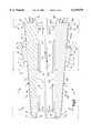
- FIG. 1is an elevational view of a human spinal column having a spinal disc in accordance with the present invention between adjacent vertebrae of the spinal column;
- FIG. 2is a top perspective view of the spinal disc of FIG. 1;
- FIG. 3is a bottom plan view of the spinal disc of FIG. 1;
- FIG. 4is an elevational view, partly in section, of the spinal disc of FIG. 1, taken generally along line 4--4 of FIG. 3;
- FIG. 5is a sectional view of the spinal disc of FIG. 1, taken generally along line 5--5 of FIG. 3 and with parts removed;
- FIG. 6is an enlarged view of a portion of FIG. 4.
- FIG. 1illustrates a spinal disc prosthesis, i.e., spinal disc 10.
- the spinal disc 10is illustrated in use between adjacent upper and lower vertebrae 12 and 14 of a human spinal column 16.
- the vertebrae 12 and 14have portions which face anteriorly (to the right as viewed in FIG. 1) and portions which face posteriorly (to the left as viewed in FIG. 1).
- the disc 10comprises a first or upper rigid plate 20, a second or lower rigid plate 120, and an elastomeric core 200 interposed between and adhered to the two plates.
- the upper and lower plates 20 and 120are identical to each other, and the disc 10 is symmetrical about an anterior-posterior, horizontally extending plane A (FIG. 4) and is also symmetrical about a sagittal plane B (FIG. 3).
- the terms "upper” and “lower”are used herein with reference to the orientation of the disc 10 when it is implanted in the human body as illustrated in FIG. 1, to distinguish the two identical plates for reference purposes.
- the upper plate 20(FIG. 5) is rigid and is preferably made of a biocompatible metal such as a titanium-vanadium-aluminum alloy having about 90% by weight titanium, about 6% by weight aluminum and about 4% by weight vanadium.
- the upper plate 20can be made of any suitable biocompatible material, including but not limited to a composite plastic material.
- the upper plate 20is preferably milled out of a single block of metal.
- the upper plate 20could, however, be made in a different manner, for example, by casting.
- the upper plate 20has an anterior portion 22 and a posterior portion 24.
- the anterior portion 22 of the upper plate 20is that portion of the upper plate which is disposed anteriorly in the spine 16 when the disc 10 is implanted in the spine.
- the posterior portion 24 of the upper plate 20is that portion of the upper plate which is disposed posteriorly in the spine 16 when the disc 10 is implanted in the spine.
- the anterior portion of the upper platecan be said to be located generally on one side (to the right as viewed in FIG. 5) of an axis 28 of the disc 10; the posterior portion of the upper plate can be said to be located generally on the other side (to the left as viewed in FIG. 6) of the axis 28.
- the axis 28extends through the disc between the upper and lower plates 20 and 120.
- the axis 28extends generally along the length of the spinal column 16 when the disc 10 is implanted in the spinal column.
- the configuration of the disc 10(as viewed in plan) is designed to conform generally to the shape of a natural human spinal disc.
- the perimeter 30 (FIG. 3) of the disc 10has a flat posterior portion 32.
- the perimeter 30 of the disc 10has a curved convex portion 34 which extends between opposite ends 36 and 38 of the flat portion 32 of the perimeter.
- the perimeter 30 of the disc 10including the perimeters of the core 200 and of the plates 20 and 120, does not have any outwardly projecting lobes.
- the perimeter of the core 200has the same configuration (as viewed in plan) as the perimeter of the upper and lower plates 20 and 120.
- the upper plate 20has an inner major side surface 40 which is presented downward as viewed in FIG. 5.
- the inner major side surface 40includes all of the surface area of the upper plate 20 which is visible from below (in plan) as viewed in FIG. 5.
- the inner major side surface 40 of the upper plate 20includes a planar first surface 42 of the upper plate which extends perpendicular to the axis 28.
- the area of the first surface 42is at least 65% of the area of the inner major side surface 40 as viewed in plan, that is, with all points on the inner major side surface 40 viewed in a direction parallel to the axis 28.
- the area of the first surface 42is 75% of the area of the inner major side surface 40.
- the first surface 42is circumscribed by a first rim 44 of the upper plate 20.
- the first rim 44has a generally semi-cylindrical cross-sectional configuration as shown in FIG. 5 including an arcuate outer surface 46.
- the first surface 42forms the bottom of the recess 48.
- the outer surface 46 on the first rim 44forms a part of the inner major side surface 40 of the upper plate 20.
- the upper plate 20has an outer major side surface 50 which is presented upward as viewed in FIG. 5.
- the outer major side surface 50includes all of the surface area of the upper plate 20 which is visible from above (in plan) as viewed in FIG. 5.
- the outer major side surface 50includes a planar second surface 52 of the upper plate 20.
- the second surface 52is circumscribed by a second rim 54 of the upper plate 20.
- the area of the second surface 52is greater than the area of the first surface 42.
- the area of the second surface 52is 85% or more, and preferably 92%, of the area of the inner major side surface 40.
- the second rim 54is located outward of (as viewed in plan) the first rim 44.
- the second rim 54has an inner surface 56, which extends perpendicular to the second surface 52 and extends entirely around the upper plate 20, and a curved outer surface 58.
- the second surface 52forms the bottom of the recess 60.
- the distance by which the second rim 54 projects from the second surface 52is less than the distance by which the first rim 44 projects from the first surface 42.
- the recess 60 in the outer major side surface 50 of the upper plate 20is shallower than the recess 48 in the inner major side surface 40 of the upper plate.
- the second surface 52 of the upper plate 20is inclined relative to the first surface 42 of the upper plate.
- the second surface 52is inclined at an angle in the range of from about 1.5° to about 7.5° relative to the first surface 42. In the illustrated preferred embodiment, the second surface 52 is inclined at an angle of 5° relative to the first surface 42. In another preferred embodiment, not illustrated, the second surface 52 is inclined at an angle of 2.5° relative to the first surface 42.
- the first and second surfaces 42 and 52are oriented relative to each other so that they are closest together at the posterior portion 24 of the upper plate 20, and farthest apart at the anterior portion 22 of the upper plate.
- the second surface 52is inclined away from the first surface 42 as the second surface 52 extends from the posterior to the anterior of the disc 10.
- the first and second surfaces 42 and 52diverge as they extend from the posterior portion 24 of the upper plate 20 to the anterior portion 22 of the upper plate. This divergence of the first and second surfaces 42 and 52 gives the upper plate 20 a wedge-shaped configuration as viewed in a lateral or medial direction (FIG. 4).
- a single projection in the form of a dome 62extends from the second surface 52 of the upper plate 20.
- the dome 62has a crescent-shaped configuration including a central portion 64 and two opposite tips 66 and 68 (see FIG. 3).
- the dome 62is oriented on the second surface 52 so that the tips 66 and 68 of the crescent-shaped configuration point generally posteriorly and the central portion 64 of the crescent-shaped configuration is located anteriorly of the tips.
- the dome 62is also located anteriorly of the axis 28.
- the dome 62has a side surface 70.
- the side surface 70 of the domeincludes a generally concave surface 71 which faces posteriorly and a generally convex surface 73 which faces anteriorly.
- the concave surface 71 and the convex surface 73terminate at the tips 66 and 68 of the dome 62 to form the crescent-shaped configuration of the dome.
- the concave surface 71 and the convex surface 73each extend generally perpendicular to the second surface 52.
- a crescent-shaped top surface 72 of the domeextends between and interconnects the concave surface 71 and the convex surface 73 of the dome 62.
- the top surface 72 of the dome 62forms a part of the outer major side surface 50 of the upper plate 20.
- the top surface 72 of the dome 62 and the convex surface 73define an edge 75 on the anterior side of the spinal disc 10.
- the top surface 72 of the dome 62is inclined at a small angle to the second surface 52.
- the part of the top surface 72 which is disposed on the central or anterior portion 64 of the dome 62is farther from the second surface 52 than are the parts of the top surface which are disposed on the tips 66 and 68 of the dome.
- the central portion 64 of the dome 62projects 1.7 millimeters above the second surface 52, while the tips 66 and 68 of the dome project 1.3 millimeters above the second surface.
- the top surface 72is inclined at an angle in the range of from about 2° to about 6°, and preferably about 4°, relative to the second surface 52. In the illustrated embodiment, the top surface 72 of the dome 62 is inclined at an angle of 3.8° to the second surface 52 of the upper plate 20, that is, at an angle of 8.8° to the first surface 42.
- the outer surface 58 of the second rim 54merges with an outer peripheral side surface 74 of the upper plate 20.
- the outer peripheral side surface 74 of the upper plate 20extends perpendicular to the first surface 42 of the upper plate and also extends entirely around the upper plate. Thus, the outer peripheral side surface 74 of the upper plate 20 is not perpendicular to the plane of the second surface 52. Because of the inclination of the second surface 52 to the first surface 42, the outer peripheral side surface 74 of the upper plate 20 has a greater axial extent in the anterior portion 22 of the upper plate (to the right as viewed in FIG. 5) than in the posterior portion 24 of the upper plate (to the left as viewed in FIG. 5).
- the upper plate 20has an outer peripheral flange 78 which extends around the periphery of the upper plate.
- the flange 78has a generally planar first surface 80 which extends outward from the outer peripheral side surface 74, in a direction parallel to the first surface 42.
- the first surface 80 of the flange 78forms a part of the outer major side surface 50 of the upper plate 20.
- the flange 78has a curved second surface 82 which extends downward (as viewed in FIG. 5) and inward from the first surface 80 of the flange.
- a planar third surface 84 of the flange 78extends inward from the second surface 82, in a direction parallel to the first surface 80 of the flange and parallel to the first surface 42 of the upper plate 20.
- the third surface 84 of the flange 78lies in a plane located between the plane of the first surface 42 of the upper plate 20 and the plane of the second surface 52 of the upper plate.
- the third surface 84 of the flange 78extends from a location outward of the outer peripheral side surface 74, to a location inward of the outer peripheral side surface 74, and merges with the outer surface 46 of the first rim 44.
- the second and third surfaces 82 and 84 of the flange 78form a part of the inner major side surface 40 of the upper plate 20.
- a porous coating 90(FIGS. 4 and 6) is located in the recess 48 in the inner major side surface 40 of the upper plate 20.
- the coating 90is formed on the first surface 42 and is circumscribed by, or lies inward of, the first rim 44.
- the coating 90covers the entire extent of the first surface 42.
- the coating 90comprises a layer of small spherical particles or beads 92.
- the beads 92are preferably made of commercially pure titanium, but could be made of any suitable biocompatible material.
- the beads 92are sized such that none of the beads pass through a 25 mesh U.S. Series Sieve and all the beads pass through a 40 mesh U.S. Series Sieve.
- the beads 92are preferably adhered to the upper plate 20 by diffusion bonding.
- the beads 92can, alternatively, be applied to the upper plate 20 by any other suitable technique.
- the coating 90 of beads 92is firmly adhered to the upper plate 20 and is incapable of removal by normal abrasions. As described below, the coating 90 in combination with a primary adhesive interlocks with the material of the elastomeric core 200 to provide a strong bond between the upper plate 20 and the elastomeric core 16. The coating 90 of beads 92 does not project past the first rim 44, that is, in a downward direction as viewed in FIGS. 4 and 6.
- a porous coating 94(FIGS. 2, 4 and 6) is located in the recess 60 in the outer major side surface 50 of the upper plate 20.
- the coating 94is made from beads 96 which are the same size as, and are applied in the same manner as, the beads 92 on the first surface 42.
- the coating 94is formed on the second surface 52 of the upper plate 20 and is circumscribed by, or lies inward of, the second rim 54.
- the coating 94covers the entire extent of the second surface 52.
- the coating 94also covers the dome 62.
- the coating 94 on the second surface 52provides for ingrowth of bony tissue when the disc 10 is implanted in the spine 16.
- the coating 94 of beads 96is thicker than the depth of the recess 60.
- the beads 96 of the coating 94project axially outward past the second rim 54. This is in contrast to the coating 90, which does not project axially outward past the first rim 44.
- the lower plate 120is identical in configuration to the upper plate.
- the lower plate 120is rigid and is made from the same material as the upper plate.
- the lower plate 120(FIG. 5) has an anterior portion 122 which is disposed anteriorly in the spine 16 when the disc 10 is implanted in the spine.
- a posterior portion 124 of the lower plate 120is disposed posteriorly in the spine 16 when the disc 10 is implanted in the spine.
- the configuration of the lower plate 120 as viewed in planis the same as the configuration of the upper plate 20.
- the perimeter of the lower plate 120has a flat posterior portion and a curved convex portion which extends between opposite ends and of the flat portion of the perimeter.
- the lower plate 120like the upper plate 20, does not have any outwardly projecting lobes.
- the lower plate 120has an inner major side surface 140 (FIG. 5) which is presented upward as viewed in FIG. 5.
- the inner major side surface 140includes all of the surface area of the lower plate 120 which is visible from above (in plan) as viewed in FIG. 5.
- the inner major side surface 140 of the lower plate 120includes a planar third surface 142 of the lower plate 120 which extends perpendicular to the axis 28.
- the area of the first surface 142is at least 65% or more of the area of the inner major side surface 140 as viewed in plan, that is, with all points on the inner major side surface 140 viewed in a direction parallel to the axis 28.
- the area of the third surface 142is 75% of the area of the inner major side surface 140.
- the third surface 142is circumscribed by a first rim 144 of the lower plate 20.
- the first rim 144has a generally semi-cylindrical cross-sectional configuration as shown in FIG. 5 including an arcuate outer surface 146.
- the third surface 142forms the bottom of the recess 148.
- the outer surface 146 on the first rim 144forms a part of the inner major side surface 140 of the lower plate 120.
- the lower plate 120has an outer major side surface 150 which is presented downward as viewed in FIG. 5.
- the outer major side surface 150includes all of the surface area of the lower plate 120 which is visible from below (in plan) as viewed in FIG. 5.
- the outer major side surface 150 of the lower plate 120includes a planar fourth surface 152 of the lower plate.
- the fourth surface 152is circumscribed by a second rim 154 of the lower plate 120.
- the area of the fourth surface 152is greater than the area of the third surface 142.
- the area of the fourth surface 152is 85% or more, and preferably 92%, of the area of the inner major side surface 140.
- the second rim 154is located outward of (as viewed in plan) the first rim 144.
- the second rim 154has an inner surface 156, which extends perpendicular to the second surface 152 and extends entirely around the lower plate 120, and a curved outer surface 158.
- the fourth surface 152forms the bottom of the recess 160.
- the distance by which the second rim 154 projects from the fourth surface 152is less than the distance by which the first rim 144 projects from the third surface 142.
- the recess 160 in the outer major side surface 150 of the lower plate 120is shallower than the recess 148 in the inner major side surface 140 of the lower plate.
- the fourth surface 152 of the lower plate 120is inclined relative to the third surface 142 of the lower plate.
- the fourth surface 152is inclined at an angle in the range of from about 1.5° to about 7.5° relative to the third surface 142. In the illustrated preferred embodiment, the fourth surface 152 is inclined at an angle of 5° relative to the third surface 142. In another preferred embodiment, not illustrated, the fourth surface 152 is inclined at an angle of 2.5° relative to the third surface 142.
- the third and fourth surfaces 142 and 152are oriented relative to each other so that they are closest together at the posterior portion 124 of the lower plate 120, and farthest apart at the anterior portion 122 of the lower plate.
- the fourth surface 152is inclined away from the third surface 142 as the fourth surface 152 extends from the posterior to the anterior of the disc 10.
- the third and fourth surfaces 142 and 152diverge as they extend from the posterior portion 124 of the lower plate 120 to the anterior portion 122 of the lower plate. This divergence of the third and fourth surfaces 142 and 152 gives the lower plate 120 the same wedge-shaped configuration as the upper plate 20.
- a single projection in the form of a dome 162extends from the fourth surface 152 of the lower plate 120.
- the dome 162has a crescent-shaped configuration including a central portion 164 and two opposite tips 166 and 168 (see FIG. 3).
- the dome 162is oriented on the fourth surface 152 so that the tips 166 and 168 of the crescent-shaped configuration point generally posteriorly and the central portion 164 of the crescent-shaped configuration is located anteriorly of the tips.
- the dome 162is also located anteriorly of the axis 28.
- the dome 162has a side surface 170.
- the side surface 170 of the domeincludes a generally concave surface 171 which faces posteriorly and a generally convex surface 173 which faces anteriorly.
- the concave surface 171 and the convex surface 173terminate at the tips 166 and 168 of the dome 162 to form the crescent-shaped configuration of the dome.
- the concave surface 171 and the convex surface 173each extend generally perpendicular to the fourth surface 152.
- a crescent-shaped top surface 172 of the domeextends between and interconnects the concave surface 171 and the convex surface 173 of the dome 162.
- the top surface 172 of the dome 162forms a part of the outer major side surface 150 of the lower plate 120.
- the top surface 172 of the dome 162 and the convex surface 173define an edge 175 on the anterior side of the spinal disc 10.
- the top surface 172 of the dome 162is inclined at a small angle to the fourth surface 152.
- the part of the top surface 172 which is disposed on the central or anterior portion 164 of the dome 162is farther from the fourth surface 152 than are the parts of the top surface which are disposed on the tips 166 and 168 of the dome.
- the central portion 164 of the dome 162projects 1.7 millimeters above the fourth surface 152, while the tips 166 and 168 of the dome project 1.3 millimeters above the fourth surface.
- the top surface 172is inclined at an angle in the range of from about 2° to about 6°, and preferably about 4°, relative to the fourth surface 152. In the illustrated embodiment, the top surface 172 of the dome 162 is inclined at an angle of 3.8° to the fourth surface 152 of the lower plate 120, that is, at an angle of 8.8° to the third surface 142.
- the outer surface 158 of the second rim 154merges with an outer peripheral side surface 174 of the lower plate 120.
- the outer peripheral side surface 174extends perpendicular to the third surface 142 of the lower plate 120 and also extends entirely around the lower plate.
- the outer peripheral side surface 174 of the lower plate 120is not perpendicular to the plane of the fourth surface 152. Because of the inclination of the fourth surface 152 to the third surface 142, the outer peripheral side surface 174 of the lower plate 120 has a greater axial extent in the anterior portion 122 of the lower plate (to the right as viewed in FIG. 5) than in the posterior portion 124 of the lower plate (to the left as viewed in FIG. 5).
- the lower plate 120has an outer peripheral flange 178 which extends around the periphery of the lower plate.
- the flange 178has a generally planar first surface 180 which extends outward from the outer peripheral side surface 174, in a direction parallel to the third surface 142.
- the first surface 180 on the flange 178forms a part of the outer major side surface 150 of the lower plate 120.
- the flange 178has a curved second surface 182 which extends upward (as viewed in FIG. 5) and inward from the first surface 180 of the flange.
- a planar third surface 184 of the flange 178extends inward from the second surface 182, in a direction parallel to the first surface 180 of the flange and parallel to the third surface 142 of the lower plate 120.
- the third surface 184 of the flange 178lies in a plane located between the plane of the third surface 142 of the lower plate 120 and the plane of the fourth surface 152 of the lower plate.
- the third surface 184 of the flange 178extends from a location outward of the outer peripheral side surface 174, to a location inward of the outer peripheral side surface 174, and merges with the outer surface 146 of the first rim 144.
- the second and third surfaces 182 and 84 of the flange 178form a part of the inner major side surface 140 of the lower plate 120.
- a porous coating 190(FIG. 4) is located in the recess 148 in the inner major side surface 140 of the lower plate 120.
- the coating 190is formed on the third surface 142 and is circumscribed by, or lies inward of, the first rim 144.
- the coating 190covers the entire extent of the third surface 142.
- the coating 190comprises a layer of small spherical particles or beads 192.
- the beads 192are made from the same material as the beads 92 of the coating 90.
- the beads 192are preferably adhered to the lower plate 120 by diffusion bonding.
- the beads 192can, alternatively, be applied to the lower plate 120 by any other suitable technique.
- the coating 190 of beads 192is firmly adhered to the lower plate 120 and is incapable of removal by normal abrasions. As described below, the coating 190 in combination with a primary adhesive interlocks with the material of the elastomeric core 200 to provide a strong bond between the lower plate 120 and the elastomeric core 16. The coating 190 of beads 192 does not project axially outward of the first rim 144.
- a similar porous coating 194(FIGS. 3 and 4) is located in the recess 60 in the outer major side surface 150 of the lower plate 120.
- the coating 194is formed on the fourth surface 152 and is circumscribed by, or lies inward of, the second rim 154.
- the coating 194covers the entire extent of the fourth surface 152.
- the coating 194also covers the dome 162.
- the coating 194is made from a plurality of beads 196 which are the same as, and are applied in the same manner as, the beads 192 on the third surface 142.
- the coating 194 on the fourth surface 152provides for ingrowth of bony tissue when the disc 10 is implanted in the spine 16.
- the layer 190 of beads 196is thicker than the depth of the recess 160.
- the beads 196 of the coating 194project axially outward past the second rim 154. This is in contrast to the coating 190, which does not project axially outward past the first rim 144.
- the elastomeric core 200is preferably made of a polyolefin rubber or carbon black reinforced polyolefin rubber.
- the hardness of the elastomeric coreis 56-72 shore A durometer.
- the ultimate tensile strength of the coreis greater than 1600 psi.
- the corehas an ultimate elongation greater than 300% using the ASTM D412-87 testing method, and a tear resistance greater than 100 ppi using the ASTM D624-86 testing method.
- the elastomeric core 200is disclosed as being made of a polyolefin rubber, it can be made of any elastomeric material that simulates the characteristics of a natural disc.
- the plates 20 and 120are cleaned in a methyl ethyl ketone or similar reagent bath for approximately 25 minutes.
- the plates 20 and 120are etched, for example with a nitric hydrofluoric acid solution, to remove any oxide coating from the plates.
- the plates 20 and 120are rinsed in distilled water, and a primer is applied to the plates that will be bonded to the core 200.
- the primeris applied within about 2 hours of the etch, and at a nominal thickness of 0.35 mils. After the primer has dried for not less than 60 minutes, an adhesive is applied at a nominal thickness of 0.65 mils.
- the plates 20 and 120are then placed in a mold and the elastomeric material of the core 200 is flowed into the mold and adhered to the plates.
- the elastomeric material of the core 200is then cured to form the completed disc 10.
- the elastomeric core 200is affixed to the inner major side surface 40 of the upper plate 20.
- the core 200has a planar upper surface 202 (FIGS. 2, 4 and 6) which is affixed to and overlies the first surface 42 of the upper plate 20.
- a portion 204 of the material of the core 200extends into and interlocks with the first surface 42 of the upper plate 20, as well as with the porous coating 90 on the first surface.
- the first surface 42 of the upper plate 20is bonded to the upper surface 202 of the elastomeric core 200 and to the beads throughout the entire extent of the first surface.
- Another portion 206 (FIG. 6) of the material of the core 200extends over and is adhered to the first rim 44 on the upper plate 20.
- Another portion 208 of the material of the core 200extends over and is adhered to the planar third surface 84 of the flange 78 of the upper plate 20.
- Yet another portion 210 of the material of the core 200extends over and is adhered to the curved second surface 82 of the flange 78 of the upper plate 20.
- the material portion 210 which overlies the second surface 82 of the flange 78tapers to a zero thickness, as it approaches the first surface 80 of the flange.
- the material of the core 200is also affixed to the inner side surface 140 of the lower plate 120. A portion of the material of the core 200 extends into and interlocks with the third surface 142 of the lower plate 120, as well as with the porous coating 190 on the third surface.
- the core 200has a planar lower surface 212 (FIG. 4) which is affixed to the third surface 142 of the lower plate 120.
- the lower surface 212 of the core 200is parallel to the upper surface 202 of the core.
- the third surface 142 of the lower plate 120is bonded to the lower surface 212 of the elastomeric core 200 throughout the entire extent of the third surface.
- a portion 216 (FIG. 4) of the material of the core 200extends over and is adhered to the first rim 144 on the lower plate 120.
- Another portion 218 of the material of the core 200extends over and is adhered to the planar third surface 184 of the flange 178 of the lower plate 120.
- Yet another portion 220 of the material of the core 200extends over and is adhered to the curved second surface 182 of the flange 178 of the lower plate 120.
- the material portion 220 which overlies the second surface 182 of the flange 178tapers to a zero thickness, as it approaches the first surface 180 of the flange.
- the core 200has an exposed outer side surface 230 (FIGS. 2, 4 and 6) which extends between the upper and lower plates 20 and 120.
- the outer side surface 230 of the core 200includes a first surface portion 232 (FIGS. 4 and 6) extending substantially perpendicular to the first surface 42 of the upper plate 20.
- the first surface portion 232is located outward of the flange 78 of the upper plate 20.
- a convex second portion 234 of the outer side surface 230 of the core 200extends from the first surface portion 232, in a direction toward the lower plate 120.
- a concave third portion 236 of the outer side surface 230 of the core 200extends from the second surface portion 234, in a direction toward the lower plate 120.
- the outer side surface 230 of the core 200includes a fourth surface portion 238 extending from the third surface portion 236, in a direction substantially perpendicular to the first surface 42 of the upper plate 20 and parallel to the axis 28 of the disc 10.
- the fourth surface portion 238is disposed axially at a location between the upper plate 20 and the lower plate 120.
- the fourth surface portion 238is disposed inward of the outer periphery of the plate flanges 78 and 178, but outward of the first rims 44 and 144 of the plates.
- the fourth surface portion 238merges with a concave fifth surface portion 240 which is a mirror image of the third surface portion 236.
- the fifth surface portion 240merges with a convex sixth surface portion 242 which is a mirror image of the second surface portion 234.
- the sixth surface portion 242merges with a seventh surface portion 244 which is a mirror image of the first surface portion 232.
- the seventh surface portion 244is located outward of the flange 178 of the lower plate 120.
- the central portion of the core 200i.e. the portion of the core 200 located between the surface 42 and the surface 142, is of substantially uniform thickness. Because the central portion of the core 200 is of uniform thickness and the plates 20 and 120 are wedge-shaped, the overall configuration of the disc 10 is wedge-shaped. The disc 10 is thicker in the anterior portion 22 of the disc and is thinner in the posterior portion 24 of the disc.
- the upper plate 20When the disc 10 is in use in the spinal column 16, the upper plate 20 is affixed to the upper vertebra 12.
- the dome 62 on the upper plate 20is fitted into a corresponding single recess or cavity 260 (indicated schematically in FIG. 4) formed in the upper vertebra 12.
- the engagement of the dome 62 of the upper plate 20 in the cavity 260 in the upper vertebra 12resists relative movement between the upper plate and the upper vertebra.
- the dome 62has a maximum height from the second surface 52 of about 1.7 mm.
- the spinal disc of U.S. Pat. No. 5,017,437includes a plurality of cylindrical pegs which project about 2.6 mm from the upper and lower surfaces of the spinal disc for affixation to the vertebrae. As a result, less distraction of the two vertebrae 12 and 14 is needed to place the spinal disc 10 in the spinal column 16, than is needed to place the spinal disc of U.S. Pat. No. 5,017,437.
- the configuration of the dome 62also reduces the tendency for expulsion of the spinal disc 10 from the spinal column 16.
- the convex anterior surface 73 of the dome 62provides a relatively large vertebral contact area, as viewed in an anterior elevation (from the left as viewed in FIGS. 3 and 5), which contact area extends over about half the width of the spinal disc 10.
- the concave posterior surface 71 of the dome 62provides a relatively large vertebral contact area, as viewed in a posterior elevation (from the right as viewed in FIGS. 3 and 5), which contact area extends over about half the width of the spinal disc 10.
- the anterior edge 75 on the dome 62digs into the vertebra to resist expulsion of the spinal disc.
- the tips 66 and 68 of the dome 62act as hooks for cooperating with a removal tool (not shown) to enable removal of the spinal disc in an anterior direction.
- the crescent-shaped configuration of the dome 62better enables proper positioning of the spinal disc 10 between vertebrae, as compared to a prior art spinal disc having cylindrical pegs.
- the surgeoncan make one relatively large cavity 260 for receiving the dome 62, as compared to a plurality of small cavities for receiving the cylindrical pegs. This one large cavity makes it easier for the surgeon to adjust the position of the spinal disc 10 between vertebrae, as compared to a spinal disc which has a plurality of smaller projections.
- the porous coating 94 on the second surface 52 of the upper plate 20promotes bone ingrowth between the upper vertebra 12 and the upper plate 20.
- the second surface 52 (FIG. 6) of the upper plate 20engages the bony material of the upper vertebra 12. Interlocking engagement between the upper plate 20 and the bony material of the upper vertebra 12 is enhanced by the fact that the beads 96 of the coating 94 project axially outward past the second rim 54.
- the lower plate 120is affixed to the lower vertebra 14.
- the dome 162 on the lower plate 120is fitted into a corresponding single recess or cavity 262 (indicated schematically in FIG. 4) formed in the lower vertebra 14.
- the engagement of the dome 162 of the lower plate 120 in the cavity 262 in the lower vertebra 14resists relative movement between the lower plate and the lower vertebra.
- the configuration of the dome 162 on the lower plate 120has the same advantages as described above with reference to the dome 62 on the upper plate 20.
- the porous coating 194 on the fourth surface 152promotes bone ingrowth between the lower vertebra 14 and the lower plate 120.
- the fourth surface 152 of the lower plate 120engages the material of the lower vertebra 14. Interlocking engagement between the lower plate 120 and the bony material of the lower vertebra 14 is enhanced by the fact that the beads 196 of the coating 194 project axially outward past the second rim 154.
- the spinal disc 10does not have any outwardly projecting lobes on the posterior portion 24 of the disc. Therefore, as compared to a prior art disc having an open space between two lobes, stress is spread over a greater area, thus reducing the forces acting to separate the plates 20 and 120 from the body of elastomeric material 200.
Landscapes
- Health & Medical Sciences (AREA)
- Engineering & Computer Science (AREA)
- Biomedical Technology (AREA)
- Orthopedic Medicine & Surgery (AREA)
- Neurology (AREA)
- Heart & Thoracic Surgery (AREA)
- General Health & Medical Sciences (AREA)
- Transplantation (AREA)
- Cardiology (AREA)
- Vascular Medicine (AREA)
- Life Sciences & Earth Sciences (AREA)
- Animal Behavior & Ethology (AREA)
- Oral & Maxillofacial Surgery (AREA)
- Public Health (AREA)
- Veterinary Medicine (AREA)
- Physics & Mathematics (AREA)
- Geometry (AREA)
- Manufacturing & Machinery (AREA)
- Prostheses (AREA)
Abstract
Description
Claims (13)
Priority Applications (9)
| Application Number | Priority Date | Filing Date | Title |
|---|---|---|---|
| US08/962,578US6139579A (en) | 1997-10-31 | 1997-10-31 | Spinal disc |
| EP98957455AEP1032331B1 (en) | 1997-10-31 | 1998-10-30 | Spinal disc prosthesis |
| DE69832812TDE69832812T2 (en) | 1997-10-31 | 1998-10-30 | DISC PROSTHESIS |
| PCT/US1998/023172WO1999022675A1 (en) | 1997-10-31 | 1998-10-30 | Spinal disc prosthesis |
| KR1020007004599AKR100540000B1 (en) | 1997-10-31 | 1998-10-30 | Spinal disc prosthesis |
| JP2000518616AJP2001521780A (en) | 1997-10-31 | 1998-10-30 | Spinal disc prosthesis |
| CA002306647ACA2306647A1 (en) | 1997-10-31 | 1998-10-30 | Spinal disc prosthesis |
| AU13710/99AAU753752B2 (en) | 1997-10-31 | 1998-10-30 | Spinal disc prosthesis |
| US09/183,105US6348071B1 (en) | 1997-10-31 | 1998-10-30 | Spinal disc |
Applications Claiming Priority (1)
| Application Number | Priority Date | Filing Date | Title |
|---|---|---|---|
| US08/962,578US6139579A (en) | 1997-10-31 | 1997-10-31 | Spinal disc |
Related Child Applications (1)
| Application Number | Title | Priority Date | Filing Date |
|---|---|---|---|
| US09/183,105ContinuationUS6348071B1 (en) | 1997-10-31 | 1998-10-30 | Spinal disc |
Publications (1)
| Publication Number | Publication Date |
|---|---|
| US6139579Atrue US6139579A (en) | 2000-10-31 |
Family
ID=25506092
Family Applications (2)
| Application Number | Title | Priority Date | Filing Date |
|---|---|---|---|
| US08/962,578Expired - Fee RelatedUS6139579A (en) | 1997-10-31 | 1997-10-31 | Spinal disc |
| US09/183,105Expired - LifetimeUS6348071B1 (en) | 1997-10-31 | 1998-10-30 | Spinal disc |
Family Applications After (1)
| Application Number | Title | Priority Date | Filing Date |
|---|---|---|---|
| US09/183,105Expired - LifetimeUS6348071B1 (en) | 1997-10-31 | 1998-10-30 | Spinal disc |
Country Status (8)
| Country | Link |
|---|---|
| US (2) | US6139579A (en) |
| EP (1) | EP1032331B1 (en) |
| JP (1) | JP2001521780A (en) |
| KR (1) | KR100540000B1 (en) |
| AU (1) | AU753752B2 (en) |
| CA (1) | CA2306647A1 (en) |
| DE (1) | DE69832812T2 (en) |
| WO (1) | WO1999022675A1 (en) |
Cited By (168)
| Publication number | Priority date | Publication date | Assignee | Title |
|---|---|---|---|---|
| US20020065560A1 (en)* | 2000-06-12 | 2002-05-30 | Ortho Development Corporation | Intervertebral spacing implant system |
| US6511509B1 (en) | 1997-10-20 | 2003-01-28 | Lifenet | Textured bone allograft, method of making and using same |
| US20030033017A1 (en)* | 2001-06-29 | 2003-02-13 | The Regents Of The University Of California | Biodegradable/bioactive nucleus pulposus implant and method for treating degenerated intervertebral discs |
| US6562045B2 (en) | 2001-02-13 | 2003-05-13 | Sdgi Holdings, Inc. | Machining apparatus |
| US20030208274A1 (en)* | 2001-12-28 | 2003-11-06 | Davis Reginald J. | Pseudo arthrosis device |
| US6669732B2 (en) | 1997-10-17 | 2003-12-30 | Depuy Acromed, Inc. | Spinal disc |
| US20040133278A1 (en)* | 2002-10-31 | 2004-07-08 | Marino James F. | Spinal disc implant |
| US20040138749A1 (en)* | 2002-10-29 | 2004-07-15 | St. Francis Medical Technologies, Inc. | Artificial vertebral disk replacement implant with translating pivot point and method |
| USD493225S1 (en) | 2000-06-12 | 2004-07-20 | Ortho Development Corporation | Implant |
| US20040172135A1 (en)* | 2002-10-29 | 2004-09-02 | St. Francis Medical Technologies, Inc. | Artificial vertebral disk replacement implant with crossbar spacer and method |
| US20040210310A1 (en)* | 2002-12-10 | 2004-10-21 | Trieu Hai H. | Implant system and method for intervertebral disc augmentation |
| US20040249465A1 (en)* | 2003-06-06 | 2004-12-09 | Ferree Bret A. | Methods and apparatus for total disc replacements with oblique keels |
| US20040267367A1 (en)* | 2003-06-30 | 2004-12-30 | Depuy Acromed, Inc | Intervertebral implant with conformable endplate |
| US20050015152A1 (en)* | 2003-07-15 | 2005-01-20 | Spinal Generations | Spinal disc prosthesis system |
| US20050015150A1 (en)* | 2003-07-17 | 2005-01-20 | Lee Casey K. | Intervertebral disk and nucleus prosthesis |
| US20050021145A1 (en)* | 2003-05-27 | 2005-01-27 | Spinalmotion, Inc. | Prosthetic disc for intervertebral insertion |
| US20050055029A1 (en)* | 2003-09-10 | 2005-03-10 | Sdgi Holdings, Inc. | Artificial spinal discs and associated implantation instruments and methods |
| US20050060036A1 (en)* | 2003-05-21 | 2005-03-17 | Robert Schultz | Spinal column implant |
| US20050159819A1 (en)* | 2003-09-10 | 2005-07-21 | Sdgi Holdings, Inc. | Adjustable drill guide |
| US6949105B2 (en) | 2000-08-08 | 2005-09-27 | Sdgi Holdings, Inc. | Method and apparatus for stereotactic implantation |
| US20050216084A1 (en)* | 2003-04-22 | 2005-09-29 | Fleischmann Lewis W | Collapsible, rotatable, and tiltable hydraulic spinal disc prosthesis system with selectable modular components |
| US6966929B2 (en) | 2002-10-29 | 2005-11-22 | St. Francis Medical Technologies, Inc. | Artificial vertebral disk replacement implant with a spacer |
| US20050273111A1 (en)* | 1999-10-08 | 2005-12-08 | Ferree Bret A | Methods and apparatus for intervertebral disc removal and endplate preparation |
| US6986789B2 (en) | 2003-08-22 | 2006-01-17 | Aesculap Ag & Co. Kg | Intervertebral implant |
| US20060020342A1 (en)* | 2004-07-21 | 2006-01-26 | Ferree Bret A | Facet-preserving artificial disc replacements |
| US20060025862A1 (en)* | 2004-07-30 | 2006-02-02 | Spinalmotion, Inc. | Intervertebral prosthetic disc with metallic core |
| US20060025778A1 (en)* | 2004-07-21 | 2006-02-02 | Ferree Bret A | Methods and apparatus for artificial disc replacement (ADR) insertion and other surgical procedures |
| US20060029186A1 (en)* | 2003-01-31 | 2006-02-09 | Spinalmotion, Inc. | Spinal midline indicator |
| US7001433B2 (en) | 2002-05-23 | 2006-02-21 | Pioneer Laboratories, Inc. | Artificial intervertebral disc device |
| US20060041313A1 (en)* | 2004-08-19 | 2006-02-23 | Sdgi Holdings, Inc. | Intervertebral disc system |
| US20060052870A1 (en)* | 2004-09-09 | 2006-03-09 | Ferree Bret A | Methods and apparatus to prevent movement through artificial disc replacements |
| US7025787B2 (en) | 2001-11-26 | 2006-04-11 | Sdgi Holdings, Inc. | Implantable joint prosthesis and associated instrumentation |
| US20060167550A1 (en)* | 2002-10-08 | 2006-07-27 | Robert Snell | High precision manufacture of polyurethane products such as spinal disc implants having a gradual modulus variation |
| US20060217810A1 (en)* | 2005-03-24 | 2006-09-28 | Toussaint Leclercq | Artifical lumbar disc |
| US20060229729A1 (en)* | 2003-08-05 | 2006-10-12 | Gordon Charles R | Expandable intervertebral implant for use with instrument |
| US20060247778A1 (en)* | 2005-01-26 | 2006-11-02 | Ferree Bret A | Intradiscal devices including spacers facilitating posterior-lateral and other insertion approaches |
| US20060276800A1 (en)* | 2005-01-27 | 2006-12-07 | Nexgen Spine, Inc. | Intervertebral disc replacement and surgical instruments therefor |
| US7147665B1 (en) | 1998-07-22 | 2006-12-12 | Sdgi Holdings, Inc. | Threaded cylindrical multidiscoid single or multiple array disc prosthesis |
| US20070032874A1 (en)* | 2005-01-19 | 2007-02-08 | Nexgen Spine, Inc. | Elastomeric intervertebral disc prosthesis |
| US7198644B2 (en) | 2003-07-08 | 2007-04-03 | Aesculap Ag & Co. Kg | Intervertebral implant |
| US7217291B2 (en) | 2003-12-08 | 2007-05-15 | St. Francis Medical Technologies, Inc. | System and method for replacing degenerated spinal disks |
| US20070118225A1 (en)* | 2005-11-18 | 2007-05-24 | Zimmer Spine, Inc. | Artificial spinal discs and methods |
| US20070164464A1 (en)* | 2003-09-09 | 2007-07-19 | Spinemedica Corporation | Flexible spinal disc |
| US20070185577A1 (en)* | 2003-09-30 | 2007-08-09 | Malek Michel H | Intervertebral disc prosthesis |
| US20070239278A1 (en)* | 2006-04-06 | 2007-10-11 | Sdgi Holdings, Inc. | Intervertebral prosthetic devices and methods |
| US20070239277A1 (en)* | 2006-04-06 | 2007-10-11 | Aesculap Ag & Co. Kg | Intervertebral implant |
| WO2007121320A2 (en) | 2006-04-12 | 2007-10-25 | Spinalmotion, Inc. | Posterior spinal device and method |
| WO2006135727A3 (en)* | 2005-06-09 | 2007-11-29 | Warsaw Orthopedic Inc | Compliant porous coating |
| US20070276492A1 (en)* | 2006-05-09 | 2007-11-29 | Ranier Limited | Artificial spinal disc implant |
| US7320707B2 (en) | 2003-11-05 | 2008-01-22 | St. Francis Medical Technologies, Inc. | Method of laterally inserting an artificial vertebral disk replacement implant with crossbar spacer |
| WO2008014453A2 (en) | 2006-07-28 | 2008-01-31 | Spinalmotion, Inc. | Spinal prosthesis with multiple pillar anchors |
| US20080051900A1 (en)* | 2006-07-28 | 2008-02-28 | Spinalmotion, Inc. | Spinal Prosthesis with Offset Anchors |
| US20080077243A1 (en)* | 2006-09-26 | 2008-03-27 | Lee Casey K | Intervertebral prosthesis endplate having double dome and surgical tools for implanting same |
| US20080281423A1 (en)* | 2007-05-09 | 2008-11-13 | Ebi, L.P. | Interspinous implant |
| US20080306609A1 (en)* | 2005-01-19 | 2008-12-11 | Lee Casey K | Fixation of Elastomer to Rigid Structures |
| US7481839B2 (en) | 2003-12-02 | 2009-01-27 | Kyphon Sarl | Bioresorbable interspinous process implant for use with intervertebral disk remediation or replacement implants and procedures |
| US7481840B2 (en) | 2004-09-29 | 2009-01-27 | Kyphon Sarl | Multi-piece artificial spinal disk replacement device with selectably positioning articulating element |
| US7497859B2 (en) | 2002-10-29 | 2009-03-03 | Kyphon Sarl | Tools for implanting an artificial vertebral disk |
| US7503935B2 (en) | 2003-12-02 | 2009-03-17 | Kyphon Sarl | Method of laterally inserting an artificial vertebral disk replacement with translating pivot point |
| US20090105758A1 (en)* | 2007-10-22 | 2009-04-23 | Gimbel Jonathan A | Dampener system for a posterior stabilization system with a variable length elongated member |
| US7531001B2 (en) | 2002-09-19 | 2009-05-12 | Spinalmotion, Inc. | Intervertebral prosthesis |
| US7549995B2 (en) | 2003-07-08 | 2009-06-23 | Aesculap Ag | Surgical instrument for handling an implant |
| US7563286B2 (en) | 2002-08-15 | 2009-07-21 | Synthes Usa, Llc | Controlled artificial intervertebral disc implant |
| US7563284B2 (en) | 2002-08-15 | 2009-07-21 | Synthes Usa, Llc | Intervertebral disc implant |
| US20090192614A1 (en)* | 2008-01-25 | 2009-07-30 | Aesculap Ag | Intervertebral implant |
| US7575600B2 (en) | 2004-09-29 | 2009-08-18 | Kyphon Sarl | Artificial vertebral disk replacement implant with translating articulation contact surface and method |
| US20090216329A1 (en)* | 2005-10-24 | 2009-08-27 | Lee Casey K | Intervertebral disc replacement and associated instrumentation |
| US20090222098A1 (en)* | 2008-02-28 | 2009-09-03 | Warsaw Orthopedics, Inc. | Spinal nucleus replacement with varying modulus |
| US7585326B2 (en) | 2004-08-06 | 2009-09-08 | Spinalmotion, Inc. | Methods and apparatus for intervertebral disc prosthesis insertion |
| US7585325B2 (en) | 2004-06-16 | 2009-09-08 | Aesculap Ag | Intervertebral implant |
| US20090234457A1 (en)* | 2001-06-29 | 2009-09-17 | The Regents Of The University Of California | Systems, devices and methods for treatment of intervertebral disorders |
| US7601174B2 (en) | 2000-08-08 | 2009-10-13 | Warsaw Orthopedic, Inc. | Wear-resistant endoprosthetic devices |
| US20090270988A1 (en)* | 2008-04-24 | 2009-10-29 | Ranier Limited | Artificial spinal disc implant |
| WO2009137518A1 (en)* | 2008-05-05 | 2009-11-12 | Nexgen Spine, Inc. | Endplate for an intervertebral prosthesis and prosthesis incorporating the same |
| US7641692B2 (en) | 2000-08-08 | 2010-01-05 | Warsaw Orthopedic, Inc. | Implantable joint prosthesis |
| US7655045B2 (en) | 2003-05-06 | 2010-02-02 | Aesculap Implant Systems, Llc | Artificial intervertebral disc |
| US7670377B2 (en) | 2003-11-21 | 2010-03-02 | Kyphon Sarl | Laterally insertable artifical vertebral disk replacement implant with curved spacer |
| US20100057207A1 (en)* | 1996-10-23 | 2010-03-04 | Ray Iii Eddie F | Bone grafts |
| US7708778B2 (en) | 2003-08-05 | 2010-05-04 | Flexuspine, Inc. | Expandable articulating intervertebral implant with cam |
| US7708776B1 (en) | 2002-01-16 | 2010-05-04 | Nuvasive, Inc. | Intervertebral disk replacement system and methods |
| US20100152853A1 (en)* | 2008-12-17 | 2010-06-17 | X-Spine Systems, Inc. | Prosthetic implant with biplanar angulation and compound angles |
| US20100152745A1 (en)* | 2008-12-15 | 2010-06-17 | Spinecore, Inc. | Adjustable pin drill guide and methods therefor |
| US20100160964A1 (en)* | 2008-12-18 | 2010-06-24 | Malek Michel H | Flexible spinal stabilization system |
| US7763076B2 (en) | 2003-04-04 | 2010-07-27 | Theken Spine, Llc | Artificial disc prosthesis |
| US7785351B2 (en) | 2003-08-05 | 2010-08-31 | Flexuspine, Inc. | Artificial functional spinal implant unit system and method for use |
| US7832409B2 (en) | 2003-05-06 | 2010-11-16 | Aesculap Implant Systems, Llc | Method of inserting an artificial intervertebral disc |
| US7905922B2 (en) | 2006-12-20 | 2011-03-15 | Zimmer Spine, Inc. | Surgical implant suitable for replacement of an intervertebral disc |
| US7909869B2 (en) | 2003-08-05 | 2011-03-22 | Flexuspine, Inc. | Artificial spinal unit assemblies |
| US7935133B2 (en) | 2008-02-08 | 2011-05-03 | Mmsn Limited Partnership | Interlaminar hook |
| US7959677B2 (en) | 2007-01-19 | 2011-06-14 | Flexuspine, Inc. | Artificial functional spinal unit system and method for use |
| USRE42480E1 (en) | 1994-11-14 | 2011-06-21 | Warsaw Orthopedic, Inc. | Human spinal disc prothesis with hinges |
| US20110190888A1 (en)* | 2010-02-01 | 2011-08-04 | Bertele Theodore P | Composite Interbody Device And Method of Manufacture |
| US20110190816A1 (en)* | 2010-02-04 | 2011-08-04 | Ebi, Llc | Interspinous spacer with deployable members and related method |
| US8038718B2 (en) | 2005-03-09 | 2011-10-18 | Vertebral Technologies, Inc. | Multi-composite disc prosthesis |
| US8066750B2 (en) | 2006-10-06 | 2011-11-29 | Warsaw Orthopedic, Inc | Port structures for non-rigid bone plates |
| US8083797B2 (en) | 2005-02-04 | 2011-12-27 | Spinalmotion, Inc. | Intervertebral prosthetic disc with shock absorption |
| US20120022653A1 (en)* | 2010-07-20 | 2012-01-26 | X-Spine Systems, Inc. | Composite orthopedic implant having a low friction material substrate with primary frictional features and secondary frictional features |
| US8118869B2 (en) | 2006-03-08 | 2012-02-21 | Flexuspine, Inc. | Dynamic interbody device |
| US8157844B2 (en) | 2007-10-22 | 2012-04-17 | Flexuspine, Inc. | Dampener system for a posterior stabilization system with a variable length elongated member |
| US8162994B2 (en) | 2007-10-22 | 2012-04-24 | Flexuspine, Inc. | Posterior stabilization system with isolated, dual dampener systems |
| US8182514B2 (en) | 2007-10-22 | 2012-05-22 | Flexuspine, Inc. | Dampener system for a posterior stabilization system with a fixed length elongated member |
| US8187304B2 (en) | 2008-11-10 | 2012-05-29 | Malek Michel H | Facet fusion system |
| US8206449B2 (en) | 2008-07-17 | 2012-06-26 | Spinalmotion, Inc. | Artificial intervertebral disc placement system |
| US8241360B2 (en) | 2002-05-23 | 2012-08-14 | Pioneer Surgical Technology, Inc. | Artificial disc device |
| US8267965B2 (en) | 2007-10-22 | 2012-09-18 | Flexuspine, Inc. | Spinal stabilization systems with dynamic interbody devices |
| US8328851B2 (en) | 2005-07-28 | 2012-12-11 | Nuvasive, Inc. | Total disc replacement system and related methods |
| US8486113B2 (en) | 2003-11-25 | 2013-07-16 | Michel H. Malek | Spinal stabilization systems |
| US8506631B2 (en) | 2007-08-09 | 2013-08-13 | Spinalmotion, Inc. | Customized intervertebral prosthetic disc with shock absorption |
| US8523912B2 (en) | 2007-10-22 | 2013-09-03 | Flexuspine, Inc. | Posterior stabilization systems with shared, dual dampener systems |
| US8617214B2 (en) | 2008-01-07 | 2013-12-31 | Mmsn Limited Partnership | Spinal tension band |
| US8685035B2 (en) | 2003-01-31 | 2014-04-01 | Spinalmotion, Inc. | Intervertebral prosthesis placement instrument |
| US8758441B2 (en) | 2007-10-22 | 2014-06-24 | Spinalmotion, Inc. | Vertebral body replacement and method for spanning a space formed upon removal of a vertebral body |
| US8764833B2 (en) | 2008-03-11 | 2014-07-01 | Spinalmotion, Inc. | Artificial intervertebral disc with lower height |
| US8845730B2 (en) | 2008-07-18 | 2014-09-30 | Simplify Medical, Inc. | Posterior prosthetic intervertebral disc |
| US8940051B2 (en) | 2011-03-25 | 2015-01-27 | Flexuspine, Inc. | Interbody device insertion systems and methods |
| US9011544B2 (en) | 2008-05-05 | 2015-04-21 | Simplify Medical, Inc. | Polyaryletherketone artificial intervertebral disc |
| US9034038B2 (en) | 2008-04-11 | 2015-05-19 | Spinalmotion, Inc. | Motion limiting insert for an artificial intervertebral disc |
| US9220603B2 (en) | 2008-07-02 | 2015-12-29 | Simplify Medical, Inc. | Limited motion prosthetic intervertebral disc |
| US9220610B2 (en) | 2013-03-20 | 2015-12-29 | Kuei Jung CHEN | Textured implant device having series extendible blades |
| US9233011B2 (en) | 2006-09-15 | 2016-01-12 | Pioneer Surgical Technology, Inc. | Systems and apparatuses for inserting an implant in intervertebral space |
| US9241807B2 (en) | 2011-12-23 | 2016-01-26 | Pioneer Surgical Technology, Inc. | Systems and methods for inserting a spinal device |
| US9301787B2 (en) | 2010-09-27 | 2016-04-05 | Mmsn Limited Partnership | Medical apparatus and method for spinal surgery |
| US9345583B2 (en) | 2011-12-20 | 2016-05-24 | Warsaw Orthopedic, Inc. | Spinal implant |
| US9381047B2 (en) | 2007-05-09 | 2016-07-05 | Ebi, Llc | Interspinous implant |
| US9445916B2 (en) | 2003-10-22 | 2016-09-20 | Pioneer Surgical Technology, Inc. | Joint arthroplasty devices having articulating members |
| US9492288B2 (en) | 2013-02-20 | 2016-11-15 | Flexuspine, Inc. | Expandable fusion device for positioning between adjacent vertebral bodies |
| US9510953B2 (en) | 2012-03-16 | 2016-12-06 | Vertebral Technologies, Inc. | Modular segmented disc nucleus implant |
| US9517144B2 (en) | 2014-04-24 | 2016-12-13 | Exactech, Inc. | Limited profile intervertebral implant with incorporated fastening mechanism |
| US9526627B2 (en) | 2011-11-17 | 2016-12-27 | Exactech, Inc. | Expandable interbody device system and method |
| US9655741B2 (en) | 2003-05-27 | 2017-05-23 | Simplify Medical Pty Ltd | Prosthetic disc for intervertebral insertion |
| US9724207B2 (en) | 2003-02-14 | 2017-08-08 | DePuy Synthes Products, Inc. | In-situ formed intervertebral fusion device and method |
| US9737414B2 (en) | 2006-11-21 | 2017-08-22 | Vertebral Technologies, Inc. | Methods and apparatus for minimally invasive modular interbody fusion devices |
| WO2017189517A1 (en) | 2016-04-26 | 2017-11-02 | Alethea Spine, Llc | Orthopedic implant with integrated core |
| US9949769B2 (en) | 2004-03-06 | 2018-04-24 | DePuy Synthes Products, Inc. | Dynamized interspinal implant |
| US9987052B2 (en) | 2015-02-24 | 2018-06-05 | X-Spine Systems, Inc. | Modular interspinous fixation system with threaded component |
| US10123880B2 (en) | 2014-07-22 | 2018-11-13 | Ossaware Biotech Co., Ltd. | Expandable spinal interbody device |
| US10238500B2 (en) | 2002-06-27 | 2019-03-26 | DePuy Synthes Products, Inc. | Intervertebral disc |
| US10327910B2 (en) | 2013-03-14 | 2019-06-25 | X-Spine Systems, Inc. | Spinal implant and assembly |
| US10398565B2 (en) | 2014-04-24 | 2019-09-03 | Choice Spine, Llc | Limited profile intervertebral implant with incorporated fastening and locking mechanism |
| US10561504B2 (en) | 2016-01-19 | 2020-02-18 | K2M, Inc. | Surgical instrument and methods of use thereof |
| US10617531B2 (en) | 2015-10-26 | 2020-04-14 | K2M, Inc. | Cervical disc and instrumentation |
| US10888433B2 (en) | 2016-12-14 | 2021-01-12 | DePuy Synthes Products, Inc. | Intervertebral implant inserter and related methods |
| USD907771S1 (en) | 2017-10-09 | 2021-01-12 | Pioneer Surgical Technology, Inc. | Intervertebral implant |
| US10940016B2 (en) | 2017-07-05 | 2021-03-09 | Medos International Sarl | Expandable intervertebral fusion cage |
| US10966840B2 (en) | 2010-06-24 | 2021-04-06 | DePuy Synthes Products, Inc. | Enhanced cage insertion assembly |
| US10973652B2 (en) | 2007-06-26 | 2021-04-13 | DePuy Synthes Products, Inc. | Highly lordosed fusion cage |
| US11147682B2 (en) | 2017-09-08 | 2021-10-19 | Pioneer Surgical Technology, Inc. | Intervertebral implants, instruments, and methods |
| US11273050B2 (en) | 2006-12-07 | 2022-03-15 | DePuy Synthes Products, Inc. | Intervertebral implant |
| US11344424B2 (en) | 2017-06-14 | 2022-05-31 | Medos International Sarl | Expandable intervertebral implant and related methods |
| US11426290B2 (en) | 2015-03-06 | 2022-08-30 | DePuy Synthes Products, Inc. | Expandable intervertebral implant, system, kit and method |
| US11426286B2 (en) | 2020-03-06 | 2022-08-30 | Eit Emerging Implant Technologies Gmbh | Expandable intervertebral implant |
| US11446156B2 (en) | 2018-10-25 | 2022-09-20 | Medos International Sarl | Expandable intervertebral implant, inserter instrument, and related methods |
| US11446155B2 (en) | 2017-05-08 | 2022-09-20 | Medos International Sarl | Expandable cage |
| US11452607B2 (en) | 2010-10-11 | 2022-09-27 | DePuy Synthes Products, Inc. | Expandable interspinous process spacer implant |
| US11497619B2 (en) | 2013-03-07 | 2022-11-15 | DePuy Synthes Products, Inc. | Intervertebral implant |
| US11510788B2 (en) | 2016-06-28 | 2022-11-29 | Eit Emerging Implant Technologies Gmbh | Expandable, angularly adjustable intervertebral cages |
| US11596522B2 (en) | 2016-06-28 | 2023-03-07 | Eit Emerging Implant Technologies Gmbh | Expandable and angularly adjustable intervertebral cages with articulating joint |
| US11602438B2 (en) | 2008-04-05 | 2023-03-14 | DePuy Synthes Products, Inc. | Expandable intervertebral implant |
| US11607321B2 (en) | 2009-12-10 | 2023-03-21 | DePuy Synthes Products, Inc. | Bellows-like expandable interbody fusion cage |
| US11612491B2 (en) | 2009-03-30 | 2023-03-28 | DePuy Synthes Products, Inc. | Zero profile spinal fusion cage |
| US11654033B2 (en) | 2010-06-29 | 2023-05-23 | DePuy Synthes Products, Inc. | Distractible intervertebral implant |
| US11737881B2 (en) | 2008-01-17 | 2023-08-29 | DePuy Synthes Products, Inc. | Expandable intervertebral implant and associated method of manufacturing the same |
| US11752009B2 (en) | 2021-04-06 | 2023-09-12 | Medos International Sarl | Expandable intervertebral fusion cage |
| US11850160B2 (en) | 2021-03-26 | 2023-12-26 | Medos International Sarl | Expandable lordotic intervertebral fusion cage |
| US11911287B2 (en) | 2010-06-24 | 2024-02-27 | DePuy Synthes Products, Inc. | Lateral spondylolisthesis reduction cage |
| USRE49973E1 (en) | 2013-02-28 | 2024-05-21 | DePuy Synthes Products, Inc. | Expandable intervertebral implant, system, kit and method |
| US12090064B2 (en) | 2022-03-01 | 2024-09-17 | Medos International Sarl | Stabilization members for expandable intervertebral implants, and related systems and methods |
| US12440346B2 (en) | 2023-03-31 | 2025-10-14 | DePuy Synthes Products, Inc. | Expandable intervertebral implant |
Families Citing this family (69)
| Publication number | Priority date | Publication date | Assignee | Title |
|---|---|---|---|---|
| FR2787017B1 (en) | 1998-12-11 | 2001-04-27 | Dimso Sa | INTERVERTEBRAL DISC PROSTHESIS WITH IMPROVED MECHANICAL BEHAVIOR |
| FR2787015B1 (en)* | 1998-12-11 | 2001-04-27 | Dimso Sa | INTERVERTEBRAL DISC PROSTHESIS WITH COMPRESSIBLE BODY |
| US6241770B1 (en)* | 1999-03-05 | 2001-06-05 | Gary K. Michelson | Interbody spinal fusion implant having an anatomically conformed trailing end |
| EP1198208B1 (en)* | 1999-05-05 | 2013-07-10 | Warsaw Orthopedic, Inc. | Nested interbody spinal fusion implants |
| FR2897259B1 (en) | 2006-02-15 | 2008-05-09 | Ldr Medical Soc Par Actions Si | INTERSOMATIC TRANSFORAMINAL CAGE WITH INTERBREBAL FUSION GRAFT AND CAGE IMPLANTATION INSTRUMENT |
| DE19952939A1 (en)* | 1999-11-03 | 2001-05-10 | Tutogen Medical Gmbh | Bone material implant |
| EP1142544B1 (en)* | 2000-04-04 | 2008-03-26 | Link Spine Group, Inc. | Intervertebral implant |
| US6350283B1 (en)* | 2000-04-19 | 2002-02-26 | Gary K. Michelson | Bone hemi-lumbar interbody spinal implant having an asymmetrical leading end and method of installation thereof |
| US7462195B1 (en)* | 2000-04-19 | 2008-12-09 | Warsaw Orthopedic, Inc. | Artificial lumbar interbody spinal implant having an asymmetrical leading end |
| FR2808995B1 (en) | 2000-05-18 | 2003-02-21 | Aesculap Sa | INTERSOMATIC CAGE WITH UNIFIED GRAFT |
| ATE334644T1 (en) | 2000-10-11 | 2006-08-15 | Michael D Mason | INTEGRATED FUSION DEVICE |
| US6863689B2 (en)* | 2001-07-16 | 2005-03-08 | Spinecore, Inc. | Intervertebral spacer having a flexible wire mesh vertebral body contact element |
| US6673113B2 (en)* | 2001-10-18 | 2004-01-06 | Spinecore, Inc. | Intervertebral spacer device having arch shaped spring elements |
| US6989032B2 (en)* | 2001-07-16 | 2006-01-24 | Spinecore, Inc. | Artificial intervertebral disc |
| US7169182B2 (en) | 2001-07-16 | 2007-01-30 | Spinecore, Inc. | Implanting an artificial intervertebral disc |
| US6890355B2 (en)* | 2001-04-02 | 2005-05-10 | Gary K. Michelson | Artificial contoured spinal fusion implants made of a material other than bone |
| AU2002338239B2 (en)* | 2001-04-02 | 2005-12-22 | Warsaw Orthopedic, Inc. | Contoured spinal fusion implants |
| US6989031B2 (en)* | 2001-04-02 | 2006-01-24 | Sdgi Holdings, Inc. | Hemi-interbody spinal implant manufactured from a major long bone ring or a bone composite |
| US6749636B2 (en) | 2001-04-02 | 2004-06-15 | Gary K. Michelson | Contoured spinal fusion implants made of bone or a bone composite material |
| FR2827156B1 (en)* | 2001-07-13 | 2003-11-14 | Ldr Medical | VERTEBRAL CAGE DEVICE WITH MODULAR FASTENING |
| US7713302B2 (en)* | 2001-10-01 | 2010-05-11 | Spinecore, Inc. | Intervertebral spacer device utilizing a spirally slotted belleville washer having radially spaced concentric grooves |
| US7771477B2 (en) | 2001-10-01 | 2010-08-10 | Spinecore, Inc. | Intervertebral spacer device utilizing a belleville washer having radially spaced concentric grooves |
| US20060129242A1 (en)* | 2001-12-28 | 2006-06-15 | Brian Bergeron | Pseudo arthrosis device |
| US8038713B2 (en) | 2002-04-23 | 2011-10-18 | Spinecore, Inc. | Two-component artificial disc replacements |
| US20080027548A9 (en) | 2002-04-12 | 2008-01-31 | Ferree Bret A | Spacerless artificial disc replacements |
| AU2003286531A1 (en)* | 2002-10-21 | 2004-05-13 | 3Hbfm, Llc | Intervertebral disk prosthesis |
| US7192447B2 (en) | 2002-12-19 | 2007-03-20 | Synthes (Usa) | Intervertebral implant |
| AU2004220634B2 (en)* | 2003-03-06 | 2009-09-17 | Spinecore, Inc. | Instrumentation and methods for use in implanting a cervical disc replacement device |
| US6908484B2 (en)* | 2003-03-06 | 2005-06-21 | Spinecore, Inc. | Cervical disc replacement |
| US6981989B1 (en) | 2003-04-22 | 2006-01-03 | X-Pantu-Flex Drd Limited Liability Company | Rotatable and reversibly expandable spinal hydraulic prosthetic device |
| US20050143824A1 (en)* | 2003-05-06 | 2005-06-30 | Marc Richelsoph | Artificial intervertebral disc |
| US20090076614A1 (en)* | 2007-09-17 | 2009-03-19 | Spinalmotion, Inc. | Intervertebral Prosthetic Disc with Shock Absorption Core |
| US7655012B2 (en)* | 2003-10-02 | 2010-02-02 | Zimmer Spine, Inc. | Methods and apparatuses for minimally invasive replacement of intervertebral discs |
| DE20315613U1 (en)* | 2003-10-08 | 2003-12-11 | Aesculap Ag & Co. Kg | Intervertebral implant |
| US20050283237A1 (en)* | 2003-11-24 | 2005-12-22 | St. Francis Medical Technologies, Inc. | Artificial spinal disk replacement device with staggered vertebral body attachments |
| US20050143826A1 (en)* | 2003-12-11 | 2005-06-30 | St. Francis Medical Technologies, Inc. | Disk repair structures with anchors |
| US7250060B2 (en) | 2004-01-27 | 2007-07-31 | Sdgi Holdings, Inc. | Hybrid intervertebral disc system |
| EP2113227B1 (en) | 2004-02-04 | 2015-07-29 | LDR Medical | Intervertebral disc prosthesis |
| US20060009541A1 (en)* | 2004-07-09 | 2006-01-12 | Yih-Fang Chen | Saturant for friction material containing friction modifying layer |
| US20060069438A1 (en)* | 2004-09-29 | 2006-03-30 | Zucherman James F | Multi-piece artificial spinal disk replacement device with multi-segmented support plates |
| WO2006058221A2 (en) | 2004-11-24 | 2006-06-01 | Abdou Samy M | Devices and methods for inter-vertebral orthopedic device placement |
| AU2006203906A1 (en)* | 2005-01-08 | 2006-07-13 | Alphaspine, Inc. | Modular disc device |
| US20060178749A1 (en)* | 2005-02-10 | 2006-08-10 | Zimmer Technology, Inc. | Modular porous implant |
| EP1702965A3 (en)* | 2005-03-17 | 2007-07-25 | FUJIFILM Corporation | Metal chemical mechanical polishing solution and polishing method |
| US7799080B2 (en)* | 2005-04-22 | 2010-09-21 | Doty Keith L | Spinal disc prosthesis and methods of use |
| US7361192B2 (en)* | 2005-04-22 | 2008-04-22 | Doty Keith L | Spinal disc prosthesis and methods of use |
| FR2891135B1 (en) | 2005-09-23 | 2008-09-12 | Ldr Medical Sarl | INTERVERTEBRAL DISC PROSTHESIS |
| US20070179615A1 (en)* | 2006-01-31 | 2007-08-02 | Sdgi Holdings, Inc. | Intervertebral prosthetic disc |
| WO2007095333A2 (en)* | 2006-02-15 | 2007-08-23 | Abdou M S | Devices and methods for inter-vertebral orthopedic device placement |
| US20070233251A1 (en)* | 2006-02-18 | 2007-10-04 | Abdou M S | Use of Magnetic Fields in Orthopedic Implants |
| US8303660B1 (en) | 2006-04-22 | 2012-11-06 | Samy Abdou | Inter-vertebral disc prosthesis with variable rotational stop and methods of use |
| FR2916956B1 (en) | 2007-06-08 | 2012-12-14 | Ldr Medical | INTERSOMATIC CAGE, INTERVERTEBRAL PROSTHESIS, ANCHORING DEVICE AND IMPLANTATION INSTRUMENTATION |
| US20100191333A1 (en) | 2007-06-08 | 2010-07-29 | Morrison Iii Thomas J | Load-bearing spinal interbody device |
| US9005290B2 (en)* | 2007-06-08 | 2015-04-14 | Medgem Llc | Spinal interbody device |
| WO2009094477A1 (en)* | 2008-01-25 | 2009-07-30 | Spinalmotion, Inc. | Compliant implantable prosthetic joint with preloaded spring |
| KR100948420B1 (en) | 2009-03-05 | 2010-03-19 | 주식회사 지에스메디칼 | An artificial spinal disc |
| CN105326585B (en) | 2009-09-17 | 2018-12-11 | Ldr控股公司 | Intervertebral implant with extensible bone anchoring element |
| US8764806B2 (en) | 2009-12-07 | 2014-07-01 | Samy Abdou | Devices and methods for minimally invasive spinal stabilization and instrumentation |
| WO2011080535A1 (en) | 2009-12-31 | 2011-07-07 | Lrd Medical | Anchoring device, intervertebral implant and implantation instrument |
| US8353964B2 (en) | 2010-11-04 | 2013-01-15 | Carpenter Clyde T | Anatomic total disc replacement |
| US8845728B1 (en) | 2011-09-23 | 2014-09-30 | Samy Abdou | Spinal fixation devices and methods of use |
| US20130226240A1 (en) | 2012-02-22 | 2013-08-29 | Samy Abdou | Spinous process fixation devices and methods of use |
| FR2987256B1 (en) | 2012-02-24 | 2014-08-08 | Ldr Medical | ANCHORING DEVICE FOR INTERVERTEBRAL IMPLANT, INTERVERTEBRAL IMPLANT AND IMPLANTATION INSTRUMENTATION |
| US9198767B2 (en) | 2012-08-28 | 2015-12-01 | Samy Abdou | Devices and methods for spinal stabilization and instrumentation |
| US9320617B2 (en) | 2012-10-22 | 2016-04-26 | Cogent Spine, LLC | Devices and methods for spinal stabilization and instrumentation |
| US10857003B1 (en) | 2015-10-14 | 2020-12-08 | Samy Abdou | Devices and methods for vertebral stabilization |
| US10973648B1 (en) | 2016-10-25 | 2021-04-13 | Samy Abdou | Devices and methods for vertebral bone realignment |
| US10744000B1 (en) | 2016-10-25 | 2020-08-18 | Samy Abdou | Devices and methods for vertebral bone realignment |
| US11179248B2 (en) | 2018-10-02 | 2021-11-23 | Samy Abdou | Devices and methods for spinal implantation |
Citations (10)
| Publication number | Priority date | Publication date | Assignee | Title |
|---|---|---|---|---|
| US5071437A (en)* | 1989-02-15 | 1991-12-10 | Acromed Corporation | Artificial disc |
| WO1994000082A1 (en)* | 1992-06-30 | 1994-01-06 | Roger Paterson | Knee brace |
| US5306308A (en)* | 1989-10-23 | 1994-04-26 | Ulrich Gross | Intervertebral implant |
| EP0610837A1 (en)* | 1993-02-09 | 1994-08-17 | Acromed Corporation | Spine disc |
| US5370697A (en)* | 1992-04-21 | 1994-12-06 | Sulzer Medizinaltechnik Ag | Artificial intervertebral disk member |
| US5545229A (en)* | 1988-08-18 | 1996-08-13 | University Of Medicine And Dentistry Of Nj | Functional and biocompatible intervertebral disc spacer containing elastomeric material of varying hardness |
| US5556431A (en)* | 1992-03-13 | 1996-09-17 | B+E,Uml U+Ee Ttner-Janz; Karin | Intervertebral disc endoprosthesis |
| US5683464A (en)* | 1992-05-04 | 1997-11-04 | Sulzer Calcitek Inc. | Spinal disk implantation kit |
| US5702450A (en)* | 1993-06-28 | 1997-12-30 | Bisserie; Michel | Intervertebral disk prosthesis |
| US5716415A (en)* | 1993-10-01 | 1998-02-10 | Acromed Corporation | Spinal implant |
Family Cites Families (17)
| Publication number | Priority date | Publication date | Assignee | Title |
|---|---|---|---|---|
| DE538183C (en) | 1929-11-30 | 1931-11-11 | Jean Jacques Winckler | Tube-shaped, axially displaceable self-lubricator for the drive spindle of looms |
| CH671691A5 (en) | 1987-01-08 | 1989-09-29 | Sulzer Ag | |
| US4714469A (en) | 1987-02-26 | 1987-12-22 | Pfizer Hospital Products Group, Inc. | Spinal implant |
| CH672589A5 (en) | 1987-07-09 | 1989-12-15 | Sulzer Ag | |
| US5258043A (en) | 1987-07-20 | 1993-11-02 | Regen Corporation | Method for making a prosthetic intervertebral disc |
| DE3809793A1 (en) | 1988-03-23 | 1989-10-05 | Link Waldemar Gmbh Co | SURGICAL INSTRUMENT SET |
| US4911718A (en) | 1988-06-10 | 1990-03-27 | University Of Medicine & Dentistry Of N.J. | Functional and biocompatible intervertebral disc spacer |
| CA1333209C (en) | 1988-06-28 | 1994-11-29 | Gary Karlin Michelson | Artificial spinal fusion implants |
| US5017437A (en) | 1990-07-20 | 1991-05-21 | Carpenter Technology Corporation | Process for making clad articles and article made thereby |
| JP3007903B2 (en) | 1991-03-29 | 2000-02-14 | 京セラ株式会社 | Artificial disc |
| US5320644A (en)* | 1991-08-30 | 1994-06-14 | Sulzer Brothers Limited | Intervertebral disk prosthesis |
| DE69331586T2 (en) | 1992-11-20 | 2002-10-24 | Dennis W. Burke | IMPROVED FEMORAL CUFF IMPLANT |
| DE9216092U1 (en)* | 1992-11-26 | 1993-01-14 | S + G Implants GmbH, 2400 Lübeck | Disc-shaped implant for stiffening adjacent vertebral bones |
| JPH06178787A (en) | 1992-12-14 | 1994-06-28 | Shima Yumiko | Centrum spacer with joint, intervertebral cavity measuring device and centrum spacer pattern |
| US5397364A (en) | 1993-10-12 | 1995-03-14 | Danek Medical, Inc. | Anterior interbody fusion device |
| US5514180A (en) | 1994-01-14 | 1996-05-07 | Heggeness; Michael H. | Prosthetic intervertebral devices |
| US5480444A (en) | 1994-06-02 | 1996-01-02 | Incavo; Stephen J. | Hybrid tibial tray knee prosthesis |
- 1997
- 1997-10-31USUS08/962,578patent/US6139579A/ennot_activeExpired - Fee Related
- 1998
- 1998-10-30WOPCT/US1998/023172patent/WO1999022675A1/enactiveIP Right Grant
- 1998-10-30USUS09/183,105patent/US6348071B1/ennot_activeExpired - Lifetime
- 1998-10-30CACA002306647Apatent/CA2306647A1/ennot_activeAbandoned
- 1998-10-30DEDE69832812Tpatent/DE69832812T2/ennot_activeExpired - Fee Related
- 1998-10-30JPJP2000518616Apatent/JP2001521780A/enactivePending
- 1998-10-30EPEP98957455Apatent/EP1032331B1/ennot_activeExpired - Lifetime
- 1998-10-30AUAU13710/99Apatent/AU753752B2/ennot_activeCeased
- 1998-10-30KRKR1020007004599Apatent/KR100540000B1/ennot_activeExpired - Fee Related
Patent Citations (11)
| Publication number | Priority date | Publication date | Assignee | Title |
|---|---|---|---|---|
| US5545229A (en)* | 1988-08-18 | 1996-08-13 | University Of Medicine And Dentistry Of Nj | Functional and biocompatible intervertebral disc spacer containing elastomeric material of varying hardness |
| US5071437A (en)* | 1989-02-15 | 1991-12-10 | Acromed Corporation | Artificial disc |
| US5306308A (en)* | 1989-10-23 | 1994-04-26 | Ulrich Gross | Intervertebral implant |
| US5556431A (en)* | 1992-03-13 | 1996-09-17 | B+E,Uml U+Ee Ttner-Janz; Karin | Intervertebral disc endoprosthesis |
| US5370697A (en)* | 1992-04-21 | 1994-12-06 | Sulzer Medizinaltechnik Ag | Artificial intervertebral disk member |
| US5683464A (en)* | 1992-05-04 | 1997-11-04 | Sulzer Calcitek Inc. | Spinal disk implantation kit |
| WO1994000082A1 (en)* | 1992-06-30 | 1994-01-06 | Roger Paterson | Knee brace |
| EP0610837A1 (en)* | 1993-02-09 | 1994-08-17 | Acromed Corporation | Spine disc |
| US5534030A (en)* | 1993-02-09 | 1996-07-09 | Acromed Corporation | Spine disc |
| US5702450A (en)* | 1993-06-28 | 1997-12-30 | Bisserie; Michel | Intervertebral disk prosthesis |
| US5716415A (en)* | 1993-10-01 | 1998-02-10 | Acromed Corporation | Spinal implant |
Cited By (401)
| Publication number | Priority date | Publication date | Assignee | Title |
|---|---|---|---|---|
| USRE42576E1 (en) | 1994-11-14 | 2011-07-26 | Warsaw Orthopedic, Inc. | Human spinal disc prosthesis |
| USRE42480E1 (en) | 1994-11-14 | 2011-06-21 | Warsaw Orthopedic, Inc. | Human spinal disc prothesis with hinges |
| US20100057207A1 (en)* | 1996-10-23 | 2010-03-04 | Ray Iii Eddie F | Bone grafts |
| US6669732B2 (en) | 1997-10-17 | 2003-12-30 | Depuy Acromed, Inc. | Spinal disc |
| US6511509B1 (en) | 1997-10-20 | 2003-01-28 | Lifenet | Textured bone allograft, method of making and using same |
| US7147665B1 (en) | 1998-07-22 | 2006-12-12 | Sdgi Holdings, Inc. | Threaded cylindrical multidiscoid single or multiple array disc prosthesis |
| US20050273111A1 (en)* | 1999-10-08 | 2005-12-08 | Ferree Bret A | Methods and apparatus for intervertebral disc removal and endplate preparation |
| US6852127B2 (en) | 2000-06-12 | 2005-02-08 | Ortho Development Corporation | Method of implanting an intervertebral spacer |
| US20020065560A1 (en)* | 2000-06-12 | 2002-05-30 | Ortho Development Corporation | Intervertebral spacing implant system |
| US6579318B2 (en) | 2000-06-12 | 2003-06-17 | Ortho Development Corporation | Intervertebral spacer |
| USD501555S1 (en) | 2000-06-12 | 2005-02-01 | Ortho Development Corporation | Implant |
| USD493225S1 (en) | 2000-06-12 | 2004-07-20 | Ortho Development Corporation | Implant |
| USD494274S1 (en) | 2000-06-12 | 2004-08-10 | Ortho Development Corporation | Implant |
| US20060212119A1 (en)* | 2000-06-12 | 2006-09-21 | Varga Peter P | Intervertebral spacer |
| US20040186574A1 (en)* | 2000-06-12 | 2004-09-23 | Ortho Development Corporation | Intervertebral spacing implant system |
| US20040186575A1 (en)* | 2000-06-12 | 2004-09-23 | Ortho Development Corporation | Method of implanting an intervertebral spacer |
| US7641692B2 (en) | 2000-08-08 | 2010-01-05 | Warsaw Orthopedic, Inc. | Implantable joint prosthesis |
| US7601174B2 (en) | 2000-08-08 | 2009-10-13 | Warsaw Orthopedic, Inc. | Wear-resistant endoprosthetic devices |
| US7179262B2 (en) | 2000-08-08 | 2007-02-20 | Sdgi Holdings, Inc. | Method and apparatus for stereotactic implantation |
| US8092542B2 (en) | 2000-08-08 | 2012-01-10 | Warsaw Orthopedic, Inc. | Implantable joint prosthesis |
| US6949105B2 (en) | 2000-08-08 | 2005-09-27 | Sdgi Holdings, Inc. | Method and apparatus for stereotactic implantation |
| US6562045B2 (en) | 2001-02-13 | 2003-05-13 | Sdgi Holdings, Inc. | Machining apparatus |
| US20030033017A1 (en)* | 2001-06-29 | 2003-02-13 | The Regents Of The University Of California | Biodegradable/bioactive nucleus pulposus implant and method for treating degenerated intervertebral discs |
| US7641691B2 (en) | 2001-06-29 | 2010-01-05 | The Regents Of The University Of California | Biodegradable/bioactive nucleus pulposus implant and method for treating degenerated intervertebral discs |
| US7156877B2 (en) | 2001-06-29 | 2007-01-02 | The Regents Of The University Of California | Biodegradable/bioactive nucleus pulposus implant and method for treating degenerated intervertebral discs |
| US20090234457A1 (en)* | 2001-06-29 | 2009-09-17 | The Regents Of The University Of California | Systems, devices and methods for treatment of intervertebral disorders |
| US7025787B2 (en) | 2001-11-26 | 2006-04-11 | Sdgi Holdings, Inc. | Implantable joint prosthesis and associated instrumentation |
| US20030208274A1 (en)* | 2001-12-28 | 2003-11-06 | Davis Reginald J. | Pseudo arthrosis device |
| US20030229397A1 (en)* | 2001-12-28 | 2003-12-11 | Davis Reginald J. | Pseudo arthrosis device |
| US6736850B2 (en) | 2001-12-28 | 2004-05-18 | Spinal Concepts, Inc. | Vertebral pseudo arthrosis device and method |
| US7112223B2 (en) | 2001-12-28 | 2006-09-26 | Abbott Spine Inc. | Pseudo arthrosis device |
| US7708776B1 (en) | 2002-01-16 | 2010-05-04 | Nuvasive, Inc. | Intervertebral disk replacement system and methods |
| US8262731B2 (en) | 2002-05-23 | 2012-09-11 | Pioneer Surgical Technology, Inc. | Artificial disc device |
| US7001433B2 (en) | 2002-05-23 | 2006-02-21 | Pioneer Laboratories, Inc. | Artificial intervertebral disc device |
| US8241360B2 (en) | 2002-05-23 | 2012-08-14 | Pioneer Surgical Technology, Inc. | Artificial disc device |
| US9351852B2 (en) | 2002-05-23 | 2016-05-31 | Pioneer Surgical Technology, Inc. | Artificial disc device |
| US8388684B2 (en) | 2002-05-23 | 2013-03-05 | Pioneer Signal Technology, Inc. | Artificial disc device |
| US10238500B2 (en) | 2002-06-27 | 2019-03-26 | DePuy Synthes Products, Inc. | Intervertebral disc |
| US7563284B2 (en) | 2002-08-15 | 2009-07-21 | Synthes Usa, Llc | Intervertebral disc implant |
| US8435301B2 (en) | 2002-08-15 | 2013-05-07 | DePuy Synthes Products, LLC | Artificial intervertebral disc implant |
| US7563286B2 (en) | 2002-08-15 | 2009-07-21 | Synthes Usa, Llc | Controlled artificial intervertebral disc implant |
| US7731754B2 (en) | 2002-09-19 | 2010-06-08 | Spinalmotion, Inc. | Intervertebral prosthesis |
| US8262732B2 (en) | 2002-09-19 | 2012-09-11 | Spinalmotion, Inc. | Intervertebral prosthesis |
| US9839525B2 (en) | 2002-09-19 | 2017-12-12 | Simplify Medical Pty Ltd | Intervertebral prosthesis |
| US10413420B2 (en) | 2002-09-19 | 2019-09-17 | Simplify Medical Pty Ltd | Intervertebral prosthesis |
| US7531001B2 (en) | 2002-09-19 | 2009-05-12 | Spinalmotion, Inc. | Intervertebral prosthesis |
| US11707360B2 (en) | 2002-09-19 | 2023-07-25 | Simplify Medical Pty Ltd | Intervertebral prosthesis |
| US10517738B2 (en) | 2002-09-19 | 2019-12-31 | Simplify Medical Pty Ltd | Intervertebral prothesis |
| US11285013B2 (en) | 2002-09-19 | 2022-03-29 | Simplify Medical Pty Ltd | Intervertebral prosthesis |
| US11344427B2 (en) | 2002-09-19 | 2022-05-31 | Simplify Medical Pty Ltd | Intervertebral prosthesis |
| US10166113B2 (en) | 2002-09-19 | 2019-01-01 | Simplify Medical Pty Ltd | Intervertebral prosthesis |
| US8882837B2 (en) | 2002-10-08 | 2014-11-11 | Ranier Limited | High precision manufacture of polyurethane products such as spinal disc implants having gradual modulus variation |
| US20070043443A1 (en)* | 2002-10-08 | 2007-02-22 | Ranier Technology Ltd. | High precision manufacture of polyurethane products such as spinal disc implants having gradual modulus variation |
| US20070050037A1 (en)* | 2002-10-08 | 2007-03-01 | Ranier Technology Ltd. | High precision manufacture of polyurethane products such as spinal disc implants having gradual modulus variation |
| US20060167550A1 (en)* | 2002-10-08 | 2006-07-27 | Robert Snell | High precision manufacture of polyurethane products such as spinal disc implants having a gradual modulus variation |
| US20070050038A1 (en)* | 2002-10-08 | 2007-03-01 | Ranier Technology Ltd. | High precision manufacture of polyurethane products such as spinal disc implants having gradual modulus variation |
| US8353960B2 (en) | 2002-10-08 | 2013-01-15 | Ranier Limited | High precision manufacture of polyurethane products such as spinal disc implants having a gradual modulus variation |
| US6966929B2 (en) | 2002-10-29 | 2005-11-22 | St. Francis Medical Technologies, Inc. | Artificial vertebral disk replacement implant with a spacer |
| US7452379B2 (en) | 2002-10-29 | 2008-11-18 | Kyphon Sarl | Artificial vertebral disk replacement implant with crossbar spacer and method |
| US7083649B2 (en) | 2002-10-29 | 2006-08-01 | St. Francis Medical Technologies, Inc. | Artificial vertebral disk replacement implant with translating pivot point |
| US20040138749A1 (en)* | 2002-10-29 | 2004-07-15 | St. Francis Medical Technologies, Inc. | Artificial vertebral disk replacement implant with translating pivot point and method |
| US7497859B2 (en) | 2002-10-29 | 2009-03-03 | Kyphon Sarl | Tools for implanting an artificial vertebral disk |
| US20040172135A1 (en)* | 2002-10-29 | 2004-09-02 | St. Francis Medical Technologies, Inc. | Artificial vertebral disk replacement implant with crossbar spacer and method |
| US7273496B2 (en) | 2002-10-29 | 2007-09-25 | St. Francis Medical Technologies, Inc. | Artificial vertebral disk replacement implant with crossbar spacer and method |
| US20080015698A1 (en)* | 2002-10-31 | 2008-01-17 | Marino James F | Spinal disc implant |
| US20040133278A1 (en)* | 2002-10-31 | 2004-07-08 | Marino James F. | Spinal disc implant |
| US20040210310A1 (en)* | 2002-12-10 | 2004-10-21 | Trieu Hai H. | Implant system and method for intervertebral disc augmentation |
| US8685035B2 (en) | 2003-01-31 | 2014-04-01 | Spinalmotion, Inc. | Intervertebral prosthesis placement instrument |
| US7637913B2 (en) | 2003-01-31 | 2009-12-29 | Spinalmotion, Inc. | Spinal midline indicator |
| US8090428B2 (en) | 2003-01-31 | 2012-01-03 | Spinalmotion, Inc. | Spinal midline indicator |
| US9402745B2 (en) | 2003-01-31 | 2016-08-02 | Simplify Medical, Inc. | Intervertebral prosthesis placement instrument |
| US10105131B2 (en) | 2003-01-31 | 2018-10-23 | Simplify Medical Pty Ltd | Intervertebral prosthesis placement instrument |
| US20060029186A1 (en)* | 2003-01-31 | 2006-02-09 | Spinalmotion, Inc. | Spinal midline indicator |
| US9801729B2 (en) | 2003-02-14 | 2017-10-31 | DePuy Synthes Products, Inc. | In-situ formed intervertebral fusion device and method |
| US10786361B2 (en) | 2003-02-14 | 2020-09-29 | DePuy Synthes Products, Inc. | In-situ formed intervertebral fusion device and method |
| US9724207B2 (en) | 2003-02-14 | 2017-08-08 | DePuy Synthes Products, Inc. | In-situ formed intervertebral fusion device and method |
| US10492918B2 (en) | 2003-02-14 | 2019-12-03 | DePuy Synthes Products, Inc. | In-situ formed intervertebral fusion device and method |
| US11432938B2 (en) | 2003-02-14 | 2022-09-06 | DePuy Synthes Products, Inc. | In-situ intervertebral fusion device and method |
| US9788963B2 (en) | 2003-02-14 | 2017-10-17 | DePuy Synthes Products, Inc. | In-situ formed intervertebral fusion device and method |
| US11207187B2 (en) | 2003-02-14 | 2021-12-28 | DePuy Synthes Products, Inc. | In-situ formed intervertebral fusion device and method |
| US10583013B2 (en) | 2003-02-14 | 2020-03-10 | DePuy Synthes Products, Inc. | In-situ formed intervertebral fusion device and method |
| US11096794B2 (en) | 2003-02-14 | 2021-08-24 | DePuy Synthes Products, Inc. | In-situ formed intervertebral fusion device and method |
| US10639164B2 (en) | 2003-02-14 | 2020-05-05 | DePuy Synthes Products, Inc. | In-situ formed intervertebral fusion device and method |
| US9808351B2 (en) | 2003-02-14 | 2017-11-07 | DePuy Synthes Products, Inc. | In-situ formed intervertebral fusion device and method |
| US10433971B2 (en) | 2003-02-14 | 2019-10-08 | DePuy Synthes Products, Inc. | In-situ formed intervertebral fusion device and method |
| US10420651B2 (en) | 2003-02-14 | 2019-09-24 | DePuy Synthes Products, Inc. | In-situ formed intervertebral fusion device and method |
| US10405986B2 (en) | 2003-02-14 | 2019-09-10 | DePuy Synthes Products, Inc. | In-situ formed intervertebral fusion device and method |
| US10376372B2 (en) | 2003-02-14 | 2019-08-13 | DePuy Synthes Products, Inc. | In-situ formed intervertebral fusion device and method |
| US10085843B2 (en) | 2003-02-14 | 2018-10-02 | DePuy Synthes Products, Inc. | In-situ formed intervertebral fusion device and method |
| US9925060B2 (en) | 2003-02-14 | 2018-03-27 | DePuy Synthes Products, Inc. | In-situ formed intervertebral fusion device and method |
| US9814589B2 (en) | 2003-02-14 | 2017-11-14 | DePuy Synthes Products, Inc. | In-situ formed intervertebral fusion device and method |
| US10555817B2 (en) | 2003-02-14 | 2020-02-11 | DePuy Synthes Products, Inc. | In-situ formed intervertebral fusion device and method |
| US10575959B2 (en) | 2003-02-14 | 2020-03-03 | DePuy Synthes Products, Inc. | In-situ formed intervertebral fusion device and method |
| US9814590B2 (en) | 2003-02-14 | 2017-11-14 | DePuy Synthes Products, Inc. | In-situ formed intervertebral fusion device and method |
| US7763075B2 (en) | 2003-04-04 | 2010-07-27 | Theken Spine, Llc | Artificial disc prosthesis |
| US7806935B2 (en) | 2003-04-04 | 2010-10-05 | Theken Spine, Llc | Artificial disc prosthesis |
| US7771480B2 (en) | 2003-04-04 | 2010-08-10 | Theken Spine, Llc | Artificial disc prosthesis |
| US7771478B2 (en) | 2003-04-04 | 2010-08-10 | Theken Spine, Llc | Artificial disc prosthesis |
| US7763076B2 (en) | 2003-04-04 | 2010-07-27 | Theken Spine, Llc | Artificial disc prosthesis |
| US20050216084A1 (en)* | 2003-04-22 | 2005-09-29 | Fleischmann Lewis W | Collapsible, rotatable, and tiltable hydraulic spinal disc prosthesis system with selectable modular components |
| US7419505B2 (en) | 2003-04-22 | 2008-09-02 | Fleischmann Lewis W | Collapsible, rotatable, and tiltable hydraulic spinal disc prosthesis system with selectable modular components |
| US7655045B2 (en) | 2003-05-06 | 2010-02-02 | Aesculap Implant Systems, Llc | Artificial intervertebral disc |
| US7832409B2 (en) | 2003-05-06 | 2010-11-16 | Aesculap Implant Systems, Llc | Method of inserting an artificial intervertebral disc |
| US7766966B2 (en) | 2003-05-06 | 2010-08-03 | Aesculap Implant Systems, Llc | Artificial intervertebral disc |
| US20050060036A1 (en)* | 2003-05-21 | 2005-03-17 | Robert Schultz | Spinal column implant |
| US10342670B2 (en) | 2003-05-27 | 2019-07-09 | Simplify Medical Pty Ltd | Intervertebral prosthetic disc |
| US10219911B2 (en) | 2003-05-27 | 2019-03-05 | Simplify Medical Pty Ltd | Prosthetic disc for intervertebral insertion |
| US8771356B2 (en) | 2003-05-27 | 2014-07-08 | Spinalmotion, Inc. | Intervertebral prosthetic disc |
| US8974533B2 (en) | 2003-05-27 | 2015-03-10 | Simplify Medical, Inc. | Prosthetic disc for intervertebral insertion |
| US8454698B2 (en) | 2003-05-27 | 2013-06-04 | Spinalmotion, Inc. | Prosthetic disc for intervertebral insertion |
| US9439774B2 (en) | 2003-05-27 | 2016-09-13 | Simplify Medical Pty Ltd | Intervertebral prosthetic disc |
| US10052211B2 (en) | 2003-05-27 | 2018-08-21 | Simplify Medical Pty Ltd. | Prosthetic disc for intervertebral insertion |
| US9107762B2 (en) | 2003-05-27 | 2015-08-18 | Spinalmotion, Inc. | Intervertebral prosthetic disc with metallic core |
| US8444695B2 (en) | 2003-05-27 | 2013-05-21 | Spinalmotion, Inc. | Prosthetic disc for intervertebral insertion |
| US11771565B2 (en) | 2003-05-27 | 2023-10-03 | Simplify Medical Pty Ltd | Prosthetic disc for intervertebral insertion |
| EP2161008A2 (en) | 2003-05-27 | 2010-03-10 | Spinalmotion, Inc. | Prosthetic disc for intervertebral insertion |
| US20050021145A1 (en)* | 2003-05-27 | 2005-01-27 | Spinalmotion, Inc. | Prosthetic disc for intervertebral insertion |
| US10357376B2 (en) | 2003-05-27 | 2019-07-23 | Simplify Medical Pty Ltd | Intervertebral prosthetic disc |
| EP2226038A1 (en) | 2003-05-27 | 2010-09-08 | Spinalmotion, Inc. | Prosthetic disc for intervertebral insertion |
| US9788965B2 (en) | 2003-05-27 | 2017-10-17 | Simplify Medical Pty Ltd | Prosthetic disc for intervertebral insertion |
| US7442211B2 (en) | 2003-05-27 | 2008-10-28 | Spinalmotion, Inc. | Intervertebral prosthetic disc |
| US20050021146A1 (en)* | 2003-05-27 | 2005-01-27 | Spinalmotion, Inc. | Intervertebral prosthetic disc |
| US9655741B2 (en) | 2003-05-27 | 2017-05-23 | Simplify Medical Pty Ltd | Prosthetic disc for intervertebral insertion |
| US8845729B2 (en) | 2003-05-27 | 2014-09-30 | Simplify Medical, Inc. | Prosthetic disc for intervertebral insertion |
| US8092538B2 (en) | 2003-05-27 | 2012-01-10 | Spinalmotion, Inc. | Intervertebral prosthetic disc |
| US10342671B2 (en) | 2003-05-27 | 2019-07-09 | Simplify Medical Pty Ltd | Intervertebral prosthetic disc |
| US7753956B2 (en) | 2003-05-27 | 2010-07-13 | Spinalmotion, Inc. | Prosthetic disc for intervertebral insertion |
| US11376130B2 (en) | 2003-05-27 | 2022-07-05 | Simplify Medical Pty Ltd | Intervertebral prosthetic disc |
| USRE46802E1 (en) | 2003-05-27 | 2018-04-24 | Simplify Medical Pty Limited | Intervertebral prosthetic disc with metallic core |
| US20040249465A1 (en)* | 2003-06-06 | 2004-12-09 | Ferree Bret A. | Methods and apparatus for total disc replacements with oblique keels |
| US7048766B2 (en) | 2003-06-06 | 2006-05-23 | Ferree Bret A | Methods and apparatus for total disc replacements with oblique keels |
| US20060212121A1 (en)* | 2003-06-06 | 2006-09-21 | Bret Ferree | Method and apparatus for total disc replacements with oblique keels |
| US11612493B2 (en) | 2003-06-30 | 2023-03-28 | DePuy Synthes Products, Inc. | Intervertebral implant with conformable endplate |
| US20040267367A1 (en)* | 2003-06-30 | 2004-12-30 | Depuy Acromed, Inc | Intervertebral implant with conformable endplate |
| US20060111785A1 (en)* | 2003-06-30 | 2006-05-25 | O'neil Michael J | Intervertebral implant with conformable endplate |
| US10433974B2 (en) | 2003-06-30 | 2019-10-08 | DePuy Synthes Products, Inc. | Intervertebral implant with conformable endplate |
| US7549995B2 (en) | 2003-07-08 | 2009-06-23 | Aesculap Ag | Surgical instrument for handling an implant |
| US7198644B2 (en) | 2003-07-08 | 2007-04-03 | Aesculap Ag & Co. Kg | Intervertebral implant |
| US20100168863A1 (en)* | 2003-07-15 | 2010-07-01 | Spinal Generations, Llc | Spinal disc prosthesis system |
| US20050015152A1 (en)* | 2003-07-15 | 2005-01-20 | Spinal Generations | Spinal disc prosthesis system |
| US7695515B2 (en) | 2003-07-15 | 2010-04-13 | Spinal Generations, Llc | Spinal disc prosthesis system |
| US8337561B2 (en) | 2003-07-15 | 2012-12-25 | Spinal Generations, Llc | Spinal disc prosthesis system |
| US20050015150A1 (en)* | 2003-07-17 | 2005-01-20 | Lee Casey K. | Intervertebral disk and nucleus prosthesis |
| US20080046082A1 (en)* | 2003-07-17 | 2008-02-21 | Lee Casey K | Intervertebral disc and nucleus prosthesis |
| US8118871B2 (en) | 2003-08-05 | 2012-02-21 | Flexuspine, Inc. | Expandable articulating intervertebral implant |
| US7708778B2 (en) | 2003-08-05 | 2010-05-04 | Flexuspine, Inc. | Expandable articulating intervertebral implant with cam |
| US8257440B2 (en) | 2003-08-05 | 2012-09-04 | Gordon Charles R | Method of insertion of an expandable intervertebral implant |
| US8603168B2 (en) | 2003-08-05 | 2013-12-10 | Flexuspine, Inc. | Artificial functional spinal unit system and method for use |
| US20060229729A1 (en)* | 2003-08-05 | 2006-10-12 | Gordon Charles R | Expandable intervertebral implant for use with instrument |
| US7909869B2 (en) | 2003-08-05 | 2011-03-22 | Flexuspine, Inc. | Artificial spinal unit assemblies |
| US8172903B2 (en) | 2003-08-05 | 2012-05-08 | Gordon Charles R | Expandable intervertebral implant with spacer |
| US8147550B2 (en) | 2003-08-05 | 2012-04-03 | Flexuspine, Inc. | Expandable articulating intervertebral implant with limited articulation |
| US8123810B2 (en) | 2003-08-05 | 2012-02-28 | Gordon Charles R | Expandable intervertebral implant with wedged expansion member |
| US7799082B2 (en) | 2003-08-05 | 2010-09-21 | Flexuspine, Inc. | Artificial functional spinal unit system and method for use |
| US8052723B2 (en) | 2003-08-05 | 2011-11-08 | Flexuspine Inc. | Dynamic posterior stabilization systems and methods of use |
| US8118870B2 (en) | 2003-08-05 | 2012-02-21 | Flexuspine, Inc. | Expandable articulating intervertebral implant with spacer |
| US7794480B2 (en) | 2003-08-05 | 2010-09-14 | Flexuspine, Inc. | Artificial functional spinal unit system and method for use |
| US8753398B2 (en) | 2003-08-05 | 2014-06-17 | Charles R. Gordon | Method of inserting an expandable intervertebral implant without overdistraction |
| US7785351B2 (en) | 2003-08-05 | 2010-08-31 | Flexuspine, Inc. | Artificial functional spinal implant unit system and method for use |
| US9579124B2 (en) | 2003-08-05 | 2017-02-28 | Flexuspine, Inc. | Expandable articulating intervertebral implant with limited articulation |
| US7753958B2 (en) | 2003-08-05 | 2010-07-13 | Gordon Charles R | Expandable intervertebral implant |
| US8647386B2 (en) | 2003-08-05 | 2014-02-11 | Charles R. Gordon | Expandable intervertebral implant system and method |
| US6986789B2 (en) | 2003-08-22 | 2006-01-17 | Aesculap Ag & Co. Kg | Intervertebral implant |
| US20070164464A1 (en)* | 2003-09-09 | 2007-07-19 | Spinemedica Corporation | Flexible spinal disc |
| US20050159819A1 (en)* | 2003-09-10 | 2005-07-21 | Sdgi Holdings, Inc. | Adjustable drill guide |
| US7766914B2 (en) | 2003-09-10 | 2010-08-03 | Warsaw Orthopedic, Inc. | Adjustable drill guide |
| US7794465B2 (en) | 2003-09-10 | 2010-09-14 | Warsaw Orthopedic, Inc. | Artificial spinal discs and associated implantation instruments and methods |
| US7276082B2 (en) | 2003-09-10 | 2007-10-02 | Warsaw Orthopedic, Inc. | Artificial spinal discs and associated implantation and revision methods |
| US20050055098A1 (en)* | 2003-09-10 | 2005-03-10 | Sdgi Holdings, Inc. | Artificial spinal discs and associated implantation and revision methods |
| US20050055029A1 (en)* | 2003-09-10 | 2005-03-10 | Sdgi Holdings, Inc. | Artificial spinal discs and associated implantation instruments and methods |
| US8097038B2 (en) | 2003-09-30 | 2012-01-17 | Mmsn Limited Partnership | Prosthetic vertebral assembly |
| US7255714B2 (en) | 2003-09-30 | 2007-08-14 | Michel H. Malek | Vertically adjustable intervertebral disc prosthesis |
| US7402176B2 (en) | 2003-09-30 | 2008-07-22 | Malek Michel H | Intervertebral disc prosthesis |
| US20070185577A1 (en)* | 2003-09-30 | 2007-08-09 | Malek Michel H | Intervertebral disc prosthesis |
| US9445916B2 (en) | 2003-10-22 | 2016-09-20 | Pioneer Surgical Technology, Inc. | Joint arthroplasty devices having articulating members |
| US7520899B2 (en) | 2003-11-05 | 2009-04-21 | Kyphon Sarl | Laterally insertable artificial vertebral disk replacement implant with crossbar spacer |
| US7320707B2 (en) | 2003-11-05 | 2008-01-22 | St. Francis Medical Technologies, Inc. | Method of laterally inserting an artificial vertebral disk replacement implant with crossbar spacer |
| US7670377B2 (en) | 2003-11-21 | 2010-03-02 | Kyphon Sarl | Laterally insertable artifical vertebral disk replacement implant with curved spacer |
| US7691146B2 (en) | 2003-11-21 | 2010-04-06 | Kyphon Sarl | Method of laterally inserting an artificial vertebral disk replacement implant with curved spacer |
| US8486113B2 (en) | 2003-11-25 | 2013-07-16 | Michel H. Malek | Spinal stabilization systems |
| US7481839B2 (en) | 2003-12-02 | 2009-01-27 | Kyphon Sarl | Bioresorbable interspinous process implant for use with intervertebral disk remediation or replacement implants and procedures |
| US7503935B2 (en) | 2003-12-02 | 2009-03-17 | Kyphon Sarl | Method of laterally inserting an artificial vertebral disk replacement with translating pivot point |
| US7217291B2 (en) | 2003-12-08 | 2007-05-15 | St. Francis Medical Technologies, Inc. | System and method for replacing degenerated spinal disks |
| US7837734B2 (en) | 2003-12-08 | 2010-11-23 | Warsaw Orthopedic, Inc. | System and method for replacing degenerated spinal disks |
| US10433881B2 (en) | 2004-03-06 | 2019-10-08 | DePuy Synthes Products, Inc. | Dynamized interspinal implant |
| US9949769B2 (en) | 2004-03-06 | 2018-04-24 | DePuy Synthes Products, Inc. | Dynamized interspinal implant |
| US10512489B2 (en) | 2004-03-06 | 2019-12-24 | DePuy Synthes Products, Inc. | Dynamized interspinal implant |
| US7585325B2 (en) | 2004-06-16 | 2009-09-08 | Aesculap Ag | Intervertebral implant |
| US20060020342A1 (en)* | 2004-07-21 | 2006-01-26 | Ferree Bret A | Facet-preserving artificial disc replacements |
| US20060025778A1 (en)* | 2004-07-21 | 2006-02-02 | Ferree Bret A | Methods and apparatus for artificial disc replacement (ADR) insertion and other surgical procedures |
| US20060025862A1 (en)* | 2004-07-30 | 2006-02-02 | Spinalmotion, Inc. | Intervertebral prosthetic disc with metallic core |
| US7575599B2 (en) | 2004-07-30 | 2009-08-18 | Spinalmotion, Inc. | Intervertebral prosthetic disc with metallic core |
| US8002834B2 (en) | 2004-07-30 | 2011-08-23 | Spinalmotion, Inc. | Intervertebral prosthetic disc with metallic core |
| US8062371B2 (en) | 2004-07-30 | 2011-11-22 | Spinalmotion, Inc. | Intervertebral prosthetic disc with metallic core |
| US9839532B2 (en) | 2004-08-06 | 2017-12-12 | Simplify Medical Pty Ltd | Methods and apparatus for intervertebral disc prosthesis insertion |
| US9956091B2 (en) | 2004-08-06 | 2018-05-01 | Simplify Medical Pty Ltd | Methods and apparatus for intervertebral disc prosthesis insertion |
| US10085853B2 (en) | 2004-08-06 | 2018-10-02 | Simplify Medical Pty Ltd | Methods and apparatus for intervertebral disc prosthesis insertion |
| US8206447B2 (en) | 2004-08-06 | 2012-06-26 | Spinalmotion, Inc. | Methods and apparatus for intervertebral disc prosthesis insertion |
| EP3241529A1 (en) | 2004-08-06 | 2017-11-08 | Simplify Medical, Inc. | Methods and apparatus for intervertebral disc prosthesis insertion |
| US8974531B2 (en) | 2004-08-06 | 2015-03-10 | Simplify Medical, Inc. | Methods and apparatus for intervertebral disc prosthesis insertion |
| US10130494B2 (en) | 2004-08-06 | 2018-11-20 | Simplify Medical Pty Ltd. | Methods and apparatus for intervertebral disc prosthesis insertion |
| US10888437B2 (en) | 2004-08-06 | 2021-01-12 | Simplify Medical Pty Ltd | Methods and apparatus for intervertebral disc prosthesis insertion |
| US11857438B2 (en) | 2004-08-06 | 2024-01-02 | Simplify Medical Pty Ltd | Methods and apparatus for intervertebral disc prosthesis insertion |
| US7585326B2 (en) | 2004-08-06 | 2009-09-08 | Spinalmotion, Inc. | Methods and apparatus for intervertebral disc prosthesis insertion |
| US20060041313A1 (en)* | 2004-08-19 | 2006-02-23 | Sdgi Holdings, Inc. | Intervertebral disc system |
| US20060052870A1 (en)* | 2004-09-09 | 2006-03-09 | Ferree Bret A | Methods and apparatus to prevent movement through artificial disc replacements |
| US7575600B2 (en) | 2004-09-29 | 2009-08-18 | Kyphon Sarl | Artificial vertebral disk replacement implant with translating articulation contact surface and method |
| US7481840B2 (en) | 2004-09-29 | 2009-01-27 | Kyphon Sarl | Multi-piece artificial spinal disk replacement device with selectably positioning articulating element |
| US8864831B2 (en) | 2005-01-19 | 2014-10-21 | K2M, Inc. | Fixation of elastomer to rigid structures |
| US20070032874A1 (en)* | 2005-01-19 | 2007-02-08 | Nexgen Spine, Inc. | Elastomeric intervertebral disc prosthesis |
| US20080306609A1 (en)* | 2005-01-19 | 2008-12-11 | Lee Casey K | Fixation of Elastomer to Rigid Structures |
| US7776092B2 (en) | 2005-01-19 | 2010-08-17 | Nexgen Spine, Inc. | Elastomeric intervertebral disc prosthesis |
| US20060247778A1 (en)* | 2005-01-26 | 2006-11-02 | Ferree Bret A | Intradiscal devices including spacers facilitating posterior-lateral and other insertion approaches |
| US20060276800A1 (en)* | 2005-01-27 | 2006-12-07 | Nexgen Spine, Inc. | Intervertebral disc replacement and surgical instruments therefor |
| US8083797B2 (en) | 2005-02-04 | 2011-12-27 | Spinalmotion, Inc. | Intervertebral prosthetic disc with shock absorption |
| US8398712B2 (en) | 2005-02-04 | 2013-03-19 | Spinalmotion, Inc. | Intervertebral prosthetic disc with shock absorption |
| US8038718B2 (en) | 2005-03-09 | 2011-10-18 | Vertebral Technologies, Inc. | Multi-composite disc prosthesis |
| US8100977B2 (en) | 2005-03-09 | 2012-01-24 | Vertebral Technologies, Inc. | Interlocked modular disc nucleus prosthesis |
| US7632312B2 (en) | 2005-03-24 | 2009-12-15 | Neurocare International, Inc. | Artifical lumbar disc |
| US20060217810A1 (en)* | 2005-03-24 | 2006-09-28 | Toussaint Leclercq | Artifical lumbar disc |
| WO2006135727A3 (en)* | 2005-06-09 | 2007-11-29 | Warsaw Orthopedic Inc | Compliant porous coating |
| US8870960B2 (en) | 2005-07-28 | 2014-10-28 | Nuvasive, Inc. | Total disc replacement system and related methods |
| US9610171B2 (en) | 2005-07-28 | 2017-04-04 | Nuvasive, Inc. | Total disc replacement system and related methods |
| US8328851B2 (en) | 2005-07-28 | 2012-12-11 | Nuvasive, Inc. | Total disc replacement system and related methods |
| US9168149B2 (en) | 2005-07-28 | 2015-10-27 | NaVasive, Inc. | Total disc replacement system and related methods |
| US20090216329A1 (en)* | 2005-10-24 | 2009-08-27 | Lee Casey K | Intervertebral disc replacement and associated instrumentation |
| US9277930B2 (en) | 2005-10-24 | 2016-03-08 | K2M, Inc. | Intervertebral disc replacement and associated instrumentation |
| US8814938B2 (en) | 2005-10-24 | 2014-08-26 | K2M, Inc. | Intervertebral disc replacement and associated instrumentation |
| US7419506B2 (en) | 2005-11-18 | 2008-09-02 | Zimmer Spine, Inc. | Artificial spinal discs and methods |
| US20070118225A1 (en)* | 2005-11-18 | 2007-05-24 | Zimmer Spine, Inc. | Artificial spinal discs and methods |
| US8118869B2 (en) | 2006-03-08 | 2012-02-21 | Flexuspine, Inc. | Dynamic interbody device |
| US20070239277A1 (en)* | 2006-04-06 | 2007-10-11 | Aesculap Ag & Co. Kg | Intervertebral implant |
| US20070239278A1 (en)* | 2006-04-06 | 2007-10-11 | Sdgi Holdings, Inc. | Intervertebral prosthetic devices and methods |
| US8801792B2 (en) | 2006-04-12 | 2014-08-12 | Spinalmotion, Inc. | Posterio spinal device and method |
| WO2007121320A2 (en) | 2006-04-12 | 2007-10-25 | Spinalmotion, Inc. | Posterior spinal device and method |
| US8486147B2 (en) | 2006-04-12 | 2013-07-16 | Spinalmotion, Inc. | Posterior spinal device and method |
| US8734519B2 (en) | 2006-04-12 | 2014-05-27 | Spinalmotion, Inc. | Posterior spinal device and method |
| USRE47796E1 (en) | 2006-04-12 | 2020-01-07 | Simplify Medical Pty Ltd | Posterior spinal device and method |
| US20070276492A1 (en)* | 2006-05-09 | 2007-11-29 | Ranier Limited | Artificial spinal disc implant |
| US20080051901A1 (en)* | 2006-07-28 | 2008-02-28 | Spinalmotion, Inc. | Spinal Prosthesis with Multiple Pillar Anchors |
| WO2008014453A2 (en) | 2006-07-28 | 2008-01-31 | Spinalmotion, Inc. | Spinal prosthesis with multiple pillar anchors |
| US20080051900A1 (en)* | 2006-07-28 | 2008-02-28 | Spinalmotion, Inc. | Spinal Prosthesis with Offset Anchors |
| US9693872B2 (en) | 2006-09-15 | 2017-07-04 | Pioneer Surgical Technology, Inc. | Intervertebral disc implant |
| US9233011B2 (en) | 2006-09-15 | 2016-01-12 | Pioneer Surgical Technology, Inc. | Systems and apparatuses for inserting an implant in intervertebral space |
| US10080667B2 (en) | 2006-09-15 | 2018-09-25 | Pioneer Surgical Technology, Inc. | Intervertebral disc implant |
| US20080077243A1 (en)* | 2006-09-26 | 2008-03-27 | Lee Casey K | Intervertebral prosthesis endplate having double dome and surgical tools for implanting same |
| US9011542B2 (en) | 2006-09-26 | 2015-04-21 | K2M, Inc. | Intervertebral prosthesis endplate having double dome and surgical tools for implanting same |
| US9642631B2 (en) | 2006-09-26 | 2017-05-09 | K2M, Inc. | Intervertebral prosthesis endplate having double dome and surgical tools for implanting same |
| US8066750B2 (en) | 2006-10-06 | 2011-11-29 | Warsaw Orthopedic, Inc | Port structures for non-rigid bone plates |
| US9737414B2 (en) | 2006-11-21 | 2017-08-22 | Vertebral Technologies, Inc. | Methods and apparatus for minimally invasive modular interbody fusion devices |
| US11491023B2 (en) | 2006-11-21 | 2022-11-08 | Next Orthosurgical, Inc. | Methods and apparatus for minimally invasive modular interbody fusion devices |
| US10195048B2 (en) | 2006-11-21 | 2019-02-05 | Vertebral Technologies, Inc. | Methods and apparatus for minimally invasive modular interbody fusion devices |
| US11497618B2 (en) | 2006-12-07 | 2022-11-15 | DePuy Synthes Products, Inc. | Intervertebral implant |
| US11642229B2 (en) | 2006-12-07 | 2023-05-09 | DePuy Synthes Products, Inc. | Intervertebral implant |
| US11660206B2 (en) | 2006-12-07 | 2023-05-30 | DePuy Synthes Products, Inc. | Intervertebral implant |
| US11432942B2 (en) | 2006-12-07 | 2022-09-06 | DePuy Synthes Products, Inc. | Intervertebral implant |
| US11273050B2 (en) | 2006-12-07 | 2022-03-15 | DePuy Synthes Products, Inc. | Intervertebral implant |
| US11712345B2 (en) | 2006-12-07 | 2023-08-01 | DePuy Synthes Products, Inc. | Intervertebral implant |
| US7905922B2 (en) | 2006-12-20 | 2011-03-15 | Zimmer Spine, Inc. | Surgical implant suitable for replacement of an intervertebral disc |
| US8597358B2 (en) | 2007-01-19 | 2013-12-03 | Flexuspine, Inc. | Dynamic interbody devices |
| US7959677B2 (en) | 2007-01-19 | 2011-06-14 | Flexuspine, Inc. | Artificial functional spinal unit system and method for use |
| US9066811B2 (en) | 2007-01-19 | 2015-06-30 | Flexuspine, Inc. | Artificial functional spinal unit system and method for use |
| US8940022B2 (en) | 2007-01-19 | 2015-01-27 | Flexuspine, Inc. | Artificial functional spinal unit system and method for use |
| US8377098B2 (en) | 2007-01-19 | 2013-02-19 | Flexuspine, Inc. | Artificial functional spinal unit system and method for use |
| US20080281423A1 (en)* | 2007-05-09 | 2008-11-13 | Ebi, L.P. | Interspinous implant |
| US9381047B2 (en) | 2007-05-09 | 2016-07-05 | Ebi, Llc | Interspinous implant |
| US10390864B2 (en) | 2007-05-09 | 2019-08-27 | Zimmer Biomet Spine, Inc. | Interspinous implant |
| US9173686B2 (en) | 2007-05-09 | 2015-11-03 | Ebi, Llc | Interspinous implant |
| US10973652B2 (en) | 2007-06-26 | 2021-04-13 | DePuy Synthes Products, Inc. | Highly lordosed fusion cage |
| US11622868B2 (en) | 2007-06-26 | 2023-04-11 | DePuy Synthes Products, Inc. | Highly lordosed fusion cage |
| US8506631B2 (en) | 2007-08-09 | 2013-08-13 | Spinalmotion, Inc. | Customized intervertebral prosthetic disc with shock absorption |
| US9687355B2 (en) | 2007-08-09 | 2017-06-27 | Simplify Medical Pty Ltd | Customized intervertebral prosthetic disc with shock absorption |
| US12029656B2 (en) | 2007-08-09 | 2024-07-09 | Globus Medical Inc. | Customized intervertebral prosthetic disc with shock absorption |
| US9827108B2 (en) | 2007-08-09 | 2017-11-28 | Simplify Medical Pty Ltd | Customized intervertebral prosthetic disc with shock absorption |
| US10548739B2 (en) | 2007-08-09 | 2020-02-04 | Simplify Medical Pty Ltd | Customized intervertebral prosthetic disc with shock absorption |
| US11229526B2 (en) | 2007-08-09 | 2022-01-25 | Simplify Medical Pty Ltd. | Customized intervertebral prosthetic disc with shock absorption |
| US9554917B2 (en) | 2007-08-09 | 2017-01-31 | Simplify Medical Pty Ltd | Customized intervertebral prosthetic disc with shock absorption |
| US8157844B2 (en) | 2007-10-22 | 2012-04-17 | Flexuspine, Inc. | Dampener system for a posterior stabilization system with a variable length elongated member |
| US8267965B2 (en) | 2007-10-22 | 2012-09-18 | Flexuspine, Inc. | Spinal stabilization systems with dynamic interbody devices |
| US8758441B2 (en) | 2007-10-22 | 2014-06-24 | Spinalmotion, Inc. | Vertebral body replacement and method for spanning a space formed upon removal of a vertebral body |
| US11364129B2 (en) | 2007-10-22 | 2022-06-21 | Simplify Medical Pty Ltd | Method and spacer device for spanning a space formed upon removal of an intervertebral disc |
| US8187330B2 (en) | 2007-10-22 | 2012-05-29 | Flexuspine, Inc. | Dampener system for a posterior stabilization system with a variable length elongated member |
| US20090105758A1 (en)* | 2007-10-22 | 2009-04-23 | Gimbel Jonathan A | Dampener system for a posterior stabilization system with a variable length elongated member |
| USRE47470E1 (en) | 2007-10-22 | 2019-07-02 | Simplify Medical Pty Ltd | Vertebral body placement and method for spanning a space formed upon removal of a vertebral body |
| US8523912B2 (en) | 2007-10-22 | 2013-09-03 | Flexuspine, Inc. | Posterior stabilization systems with shared, dual dampener systems |
| US8162994B2 (en) | 2007-10-22 | 2012-04-24 | Flexuspine, Inc. | Posterior stabilization system with isolated, dual dampener systems |
| US8182514B2 (en) | 2007-10-22 | 2012-05-22 | Flexuspine, Inc. | Dampener system for a posterior stabilization system with a fixed length elongated member |
| US8617214B2 (en) | 2008-01-07 | 2013-12-31 | Mmsn Limited Partnership | Spinal tension band |
| US11737881B2 (en) | 2008-01-17 | 2023-08-29 | DePuy Synthes Products, Inc. | Expandable intervertebral implant and associated method of manufacturing the same |
| US20090192614A1 (en)* | 2008-01-25 | 2009-07-30 | Aesculap Ag | Intervertebral implant |
| US8021424B2 (en) | 2008-01-25 | 2011-09-20 | Aesculap Ag | Intervertebral implant |
| US7935133B2 (en) | 2008-02-08 | 2011-05-03 | Mmsn Limited Partnership | Interlaminar hook |
| US20090222098A1 (en)* | 2008-02-28 | 2009-09-03 | Warsaw Orthopedics, Inc. | Spinal nucleus replacement with varying modulus |
| US8764833B2 (en) | 2008-03-11 | 2014-07-01 | Spinalmotion, Inc. | Artificial intervertebral disc with lower height |
| US12138171B2 (en) | 2008-03-11 | 2024-11-12 | Simplify Medical Pty Ltd. | Artificial intervertebral disc with lower height |
| US10517733B2 (en) | 2008-03-11 | 2019-12-31 | Simplify Medical Pty Ltd | Artificial intervertebral disc with lower height |
| US9439775B2 (en) | 2008-03-11 | 2016-09-13 | Simplify Medical Pty Ltd | Artificial intervertebral disc with lower height |
| US9883945B2 (en) | 2008-03-11 | 2018-02-06 | Simplify Medical Pty Ltd | Artificial intervertebral disc with lower height |
| US9668878B2 (en) | 2008-03-11 | 2017-06-06 | Simplify Medical Pty Ltd | Artificial intervertebral disc with lower height |
| US11357633B2 (en) | 2008-03-11 | 2022-06-14 | Simplify Medical Pty Ltd | Artificial intervertebral disc with lower height |
| US11712342B2 (en) | 2008-04-05 | 2023-08-01 | DePuy Synthes Products, Inc. | Expandable intervertebral implant |
| US12023255B2 (en) | 2008-04-05 | 2024-07-02 | DePuy Synthes Products, Inc. | Expandable inter vertebral implant |
| US11602438B2 (en) | 2008-04-05 | 2023-03-14 | DePuy Synthes Products, Inc. | Expandable intervertebral implant |
| US12011361B2 (en) | 2008-04-05 | 2024-06-18 | DePuy Synthes Products, Inc. | Expandable intervertebral implant |
| US11712341B2 (en) | 2008-04-05 | 2023-08-01 | DePuy Synthes Products, Inc. | Expandable intervertebral implant |
| US11617655B2 (en) | 2008-04-05 | 2023-04-04 | DePuy Synthes Products, Inc. | Expandable intervertebral implant |
| US11707359B2 (en) | 2008-04-05 | 2023-07-25 | DePuy Synthes Products, Inc. | Expandable intervertebral implant |
| US11701234B2 (en) | 2008-04-05 | 2023-07-18 | DePuy Synthes Products, Inc. | Expandable intervertebral implant |
| US9034038B2 (en) | 2008-04-11 | 2015-05-19 | Spinalmotion, Inc. | Motion limiting insert for an artificial intervertebral disc |
| US20090270988A1 (en)* | 2008-04-24 | 2009-10-29 | Ranier Limited | Artificial spinal disc implant |
| WO2009137518A1 (en)* | 2008-05-05 | 2009-11-12 | Nexgen Spine, Inc. | Endplate for an intervertebral prosthesis and prosthesis incorporating the same |
| US20110060416A1 (en)* | 2008-05-05 | 2011-03-10 | Ogilvie William F | Endplate for an intervertebral prosthesis and prosthesis incorporating the same |
| US9011544B2 (en) | 2008-05-05 | 2015-04-21 | Simplify Medical, Inc. | Polyaryletherketone artificial intervertebral disc |
| US11207190B2 (en) | 2008-05-05 | 2021-12-28 | Simplify Medical Pty Ltd | Polyaryletherketone artificial intervertebral disc |
| US8470045B2 (en)* | 2008-05-05 | 2013-06-25 | K2M, Inc. | Endplate for an intervertebral prosthesis and prosthesis incorporating the same |
| US9220603B2 (en) | 2008-07-02 | 2015-12-29 | Simplify Medical, Inc. | Limited motion prosthetic intervertebral disc |
| US8206449B2 (en) | 2008-07-17 | 2012-06-26 | Spinalmotion, Inc. | Artificial intervertebral disc placement system |
| US8636805B2 (en) | 2008-07-17 | 2014-01-28 | Spinalmotion, Inc. | Artificial intervertebral disc placement system |
| US9351846B2 (en) | 2008-07-18 | 2016-05-31 | Simplify Medical, Inc. | Posterior prosthetic intervertebral disc |
| US11324605B2 (en) | 2008-07-18 | 2022-05-10 | Simplify Medical Pty Ltd | Posterior prosthetic intervertebral disc |
| US11413156B2 (en) | 2008-07-18 | 2022-08-16 | Simplify Medical Pty Ltd. | Posterior prosthetic intervertebral disc |
| US11986395B2 (en) | 2008-07-18 | 2024-05-21 | Simplify Medical Pty Ltd | Posterior prosthetic intervertebral disc |
| US8845730B2 (en) | 2008-07-18 | 2014-09-30 | Simplify Medical, Inc. | Posterior prosthetic intervertebral disc |
| US8187304B2 (en) | 2008-11-10 | 2012-05-29 | Malek Michel H | Facet fusion system |
| US20100152745A1 (en)* | 2008-12-15 | 2010-06-17 | Spinecore, Inc. | Adjustable pin drill guide and methods therefor |
| US8323292B2 (en) | 2008-12-15 | 2012-12-04 | Spinecore, Inc. | Adjustable pin drill guide and methods therefor |
| US20100152853A1 (en)* | 2008-12-17 | 2010-06-17 | X-Spine Systems, Inc. | Prosthetic implant with biplanar angulation and compound angles |
| US8216316B2 (en) | 2008-12-17 | 2012-07-10 | X-Spine Systems, Inc. | Prosthetic implant with biplanar angulation and compound angles |
| US9492214B2 (en) | 2008-12-18 | 2016-11-15 | Michel H. Malek | Flexible spinal stabilization system |
| US20100160964A1 (en)* | 2008-12-18 | 2010-06-24 | Malek Michel H | Flexible spinal stabilization system |
| US11612491B2 (en) | 2009-03-30 | 2023-03-28 | DePuy Synthes Products, Inc. | Zero profile spinal fusion cage |
| US12097124B2 (en) | 2009-03-30 | 2024-09-24 | DePuy Synthes Products, Inc. | Zero profile spinal fusion cage |
| US11607321B2 (en) | 2009-12-10 | 2023-03-21 | DePuy Synthes Products, Inc. | Bellows-like expandable interbody fusion cage |
| US8303879B2 (en)* | 2010-02-01 | 2012-11-06 | Sb Technologies, Llc | Composite interbody device and method of manufacture |
| US20110190888A1 (en)* | 2010-02-01 | 2011-08-04 | Bertele Theodore P | Composite Interbody Device And Method of Manufacture |
| US10136994B2 (en) | 2010-02-01 | 2018-11-27 | Sb Technologies, Llc | Composite interbody device and associated manufacturing method |
| US20110190816A1 (en)* | 2010-02-04 | 2011-08-04 | Ebi, Llc | Interspinous spacer with deployable members and related method |
| US8388656B2 (en) | 2010-02-04 | 2013-03-05 | Ebi, Llc | Interspinous spacer with deployable members and related method |
| US9271764B2 (en) | 2010-02-04 | 2016-03-01 | Ebi, Llc | Interspinous spacer with deployable members and related method |
| US11911287B2 (en) | 2010-06-24 | 2024-02-27 | DePuy Synthes Products, Inc. | Lateral spondylolisthesis reduction cage |
| US11872139B2 (en) | 2010-06-24 | 2024-01-16 | DePuy Synthes Products, Inc. | Enhanced cage insertion assembly |
| US12318304B2 (en) | 2010-06-24 | 2025-06-03 | DePuy Synthes Products, Inc. | Lateral spondylolisthesis reduction cage |
| US10966840B2 (en) | 2010-06-24 | 2021-04-06 | DePuy Synthes Products, Inc. | Enhanced cage insertion assembly |
| US11654033B2 (en) | 2010-06-29 | 2023-05-23 | DePuy Synthes Products, Inc. | Distractible intervertebral implant |
| US20120022653A1 (en)* | 2010-07-20 | 2012-01-26 | X-Spine Systems, Inc. | Composite orthopedic implant having a low friction material substrate with primary frictional features and secondary frictional features |
| US8979934B2 (en) | 2010-07-20 | 2015-03-17 | X-Spine Systems, Inc. | Composite orthopedic implant having a low friction material substrate with primary frictional features and secondary frictional features |
| US9301787B2 (en) | 2010-09-27 | 2016-04-05 | Mmsn Limited Partnership | Medical apparatus and method for spinal surgery |
| US11452607B2 (en) | 2010-10-11 | 2022-09-27 | DePuy Synthes Products, Inc. | Expandable interspinous process spacer implant |
| US8940051B2 (en) | 2011-03-25 | 2015-01-27 | Flexuspine, Inc. | Interbody device insertion systems and methods |
| US9526627B2 (en) | 2011-11-17 | 2016-12-27 | Exactech, Inc. | Expandable interbody device system and method |
| US9345583B2 (en) | 2011-12-20 | 2016-05-24 | Warsaw Orthopedic, Inc. | Spinal implant |
| US11696786B2 (en) | 2011-12-23 | 2023-07-11 | Pioneer Surgical Technology, Inc. | Instrument for inserting a spinal device |
| US10980575B2 (en) | 2011-12-23 | 2021-04-20 | Pioneer Surgical Technology, Inc. | Instrument for inserting a spinal device |
| US9241807B2 (en) | 2011-12-23 | 2016-01-26 | Pioneer Surgical Technology, Inc. | Systems and methods for inserting a spinal device |
| US10159514B2 (en) | 2011-12-23 | 2018-12-25 | Pioneer Surgical Technology, Inc. | Method of implanting a bone plate |
| US9510953B2 (en) | 2012-03-16 | 2016-12-06 | Vertebral Technologies, Inc. | Modular segmented disc nucleus implant |
| US11246714B2 (en) | 2012-03-16 | 2022-02-15 | Sag, Llc | Surgical instrument for implanting a semi-rigid medical implant |
| US11766341B2 (en) | 2013-02-20 | 2023-09-26 | Tyler Fusion Technologies, Llc | Expandable fusion device for positioning between adjacent vertebral bodies |
| US12433764B2 (en) | 2013-02-20 | 2025-10-07 | Tyler Fusion Technologies, Llc | Expandable fusion device for positioning between adjacent vertebral bodies |
| US11369484B2 (en) | 2013-02-20 | 2022-06-28 | Flexuspine Inc. | Expandable fusion device for positioning between adjacent vertebral bodies |
| US9492288B2 (en) | 2013-02-20 | 2016-11-15 | Flexuspine, Inc. | Expandable fusion device for positioning between adjacent vertebral bodies |
| USRE49973E1 (en) | 2013-02-28 | 2024-05-21 | DePuy Synthes Products, Inc. | Expandable intervertebral implant, system, kit and method |
| US11850164B2 (en) | 2013-03-07 | 2023-12-26 | DePuy Synthes Products, Inc. | Intervertebral implant |
| US11497619B2 (en) | 2013-03-07 | 2022-11-15 | DePuy Synthes Products, Inc. | Intervertebral implant |
| US11857434B2 (en) | 2013-03-14 | 2024-01-02 | X-Spine Systems, Inc. | Spinal implant and assembly |
| US10327910B2 (en) | 2013-03-14 | 2019-06-25 | X-Spine Systems, Inc. | Spinal implant and assembly |
| US9220610B2 (en) | 2013-03-20 | 2015-12-29 | Kuei Jung CHEN | Textured implant device having series extendible blades |
| US9517144B2 (en) | 2014-04-24 | 2016-12-13 | Exactech, Inc. | Limited profile intervertebral implant with incorporated fastening mechanism |
| US11253373B2 (en) | 2014-04-24 | 2022-02-22 | Choice Spine, Llc | Limited profile intervertebral implant with incorporated fastening and locking mechanism |
| US10398565B2 (en) | 2014-04-24 | 2019-09-03 | Choice Spine, Llc | Limited profile intervertebral implant with incorporated fastening and locking mechanism |
| US10123880B2 (en) | 2014-07-22 | 2018-11-13 | Ossaware Biotech Co., Ltd. | Expandable spinal interbody device |
| US9987052B2 (en) | 2015-02-24 | 2018-06-05 | X-Spine Systems, Inc. | Modular interspinous fixation system with threaded component |
| US11426290B2 (en) | 2015-03-06 | 2022-08-30 | DePuy Synthes Products, Inc. | Expandable intervertebral implant, system, kit and method |
| US11497615B2 (en) | 2015-10-26 | 2022-11-15 | K2M, Inc. | Cervical disc and instrumentation |
| US10617531B2 (en) | 2015-10-26 | 2020-04-14 | K2M, Inc. | Cervical disc and instrumentation |
| US10561504B2 (en) | 2016-01-19 | 2020-02-18 | K2M, Inc. | Surgical instrument and methods of use thereof |
| US10918494B2 (en) | 2016-04-26 | 2021-02-16 | K2M, Inc. | Orthopedic implant with integrated core |
| EP3448318A4 (en)* | 2016-04-26 | 2019-12-04 | K2M, Inc. | ORTHOPEDIC IMPLANT WITH INTEGRATED HEART |
| WO2017189517A1 (en) | 2016-04-26 | 2017-11-02 | Alethea Spine, Llc | Orthopedic implant with integrated core |
| US11596523B2 (en) | 2016-06-28 | 2023-03-07 | Eit Emerging Implant Technologies Gmbh | Expandable and angularly adjustable articulating intervertebral cages |
| US12433757B2 (en) | 2016-06-28 | 2025-10-07 | Eit Emerging Implant Technologies Gmbh | Expandable, angularly adjustable and articulating intervertebral cages |
| US11596522B2 (en) | 2016-06-28 | 2023-03-07 | Eit Emerging Implant Technologies Gmbh | Expandable and angularly adjustable intervertebral cages with articulating joint |
| US11510788B2 (en) | 2016-06-28 | 2022-11-29 | Eit Emerging Implant Technologies Gmbh | Expandable, angularly adjustable intervertebral cages |
| US12390343B2 (en) | 2016-06-28 | 2025-08-19 | Eit Emerging Implant Technologies Gmbh | Expandable, angularly adjustable intervertebral cages |
| US10888433B2 (en) | 2016-12-14 | 2021-01-12 | DePuy Synthes Products, Inc. | Intervertebral implant inserter and related methods |
| US12427031B2 (en) | 2017-05-08 | 2025-09-30 | Medos International Sarl | Expandable cage |
| US11446155B2 (en) | 2017-05-08 | 2022-09-20 | Medos International Sarl | Expandable cage |
| US11344424B2 (en) | 2017-06-14 | 2022-05-31 | Medos International Sarl | Expandable intervertebral implant and related methods |
| US10940016B2 (en) | 2017-07-05 | 2021-03-09 | Medos International Sarl | Expandable intervertebral fusion cage |
| US12279965B2 (en) | 2017-09-08 | 2025-04-22 | Xtant Medical Holdings, Inc. | Intervertebral implants, instruments, and methods |
| US11147682B2 (en) | 2017-09-08 | 2021-10-19 | Pioneer Surgical Technology, Inc. | Intervertebral implants, instruments, and methods |
| USD907771S1 (en) | 2017-10-09 | 2021-01-12 | Pioneer Surgical Technology, Inc. | Intervertebral implant |
| USD968613S1 (en) | 2017-10-09 | 2022-11-01 | Pioneer Surgical Technology, Inc. | Intervertebral implant |
| US11446156B2 (en) | 2018-10-25 | 2022-09-20 | Medos International Sarl | Expandable intervertebral implant, inserter instrument, and related methods |
| US11806245B2 (en) | 2020-03-06 | 2023-11-07 | Eit Emerging Implant Technologies Gmbh | Expandable intervertebral implant |
| US11426286B2 (en) | 2020-03-06 | 2022-08-30 | Eit Emerging Implant Technologies Gmbh | Expandable intervertebral implant |
| US11850160B2 (en) | 2021-03-26 | 2023-12-26 | Medos International Sarl | Expandable lordotic intervertebral fusion cage |
| US12023258B2 (en) | 2021-04-06 | 2024-07-02 | Medos International Sarl | Expandable intervertebral fusion cage |
| US11752009B2 (en) | 2021-04-06 | 2023-09-12 | Medos International Sarl | Expandable intervertebral fusion cage |
| US12090064B2 (en) | 2022-03-01 | 2024-09-17 | Medos International Sarl | Stabilization members for expandable intervertebral implants, and related systems and methods |
| US12440346B2 (en) | 2023-03-31 | 2025-10-14 | DePuy Synthes Products, Inc. | Expandable intervertebral implant |
Also Published As
| Publication number | Publication date |
|---|---|
| CA2306647A1 (en) | 1999-05-14 |
| EP1032331A1 (en) | 2000-09-06 |
| KR20010031556A (en) | 2001-04-16 |
| DE69832812T2 (en) | 2006-08-17 |
| WO1999022675A1 (en) | 1999-05-14 |
| EP1032331B1 (en) | 2005-12-14 |
| DE69832812D1 (en) | 2006-01-19 |
| AU753752B2 (en) | 2002-10-24 |
| JP2001521780A (en) | 2001-11-13 |
| KR100540000B1 (en) | 2006-01-10 |
| AU1371099A (en) | 1999-05-24 |
| WO1999022675A9 (en) | 1999-08-12 |
| US6348071B1 (en) | 2002-02-19 |
Similar Documents
| Publication | Publication Date | Title |
|---|---|---|
| US6139579A (en) | Spinal disc | |
| AU754131B2 (en) | Artificial spinal disc | |
| AU730836B2 (en) | Spinal disc prosthesis | |
| US20010016773A1 (en) | Spinal disc | |
| EP1103237B1 (en) | Prosthetic implant element | |
| US20200297505A1 (en) | Internal Bone Fixation Device | |
| JPH06285099A (en) | Spinal intervertebral disk prosthesis for exchanging injured spinal intervertebral disk | |
| US10143564B2 (en) | Implantable spinal disk | |
| US8470045B2 (en) | Endplate for an intervertebral prosthesis and prosthesis incorporating the same | |
| WO2024180478A1 (en) | Vertebral prosthesis |
Legal Events
| Date | Code | Title | Description |
|---|---|---|---|
| AS | Assignment | Owner name:ACROMED CORPORATION, OHIO Free format text:ASSIGNMENT OF ASSIGNORS INTEREST;ASSIGNORS:STEFFEE, ARTHUR D.;ROSS, E. RAYMOND S.;FRASER, ROBERT D.;AND OTHERS;REEL/FRAME:008868/0644;SIGNING DATES FROM 19970811 TO 19971018 Owner name:ACROMED CORPORATION, OHIO Free format text:ASSIGNMENT OF ASSIGNORS INTEREST;ASSIGNORS:STEFFEE, ARTHUR D.;ROSS, E. RAYMOND S.;FRASER, ROBERT D.;AND OTHERS;REEL/FRAME:008868/0646;SIGNING DATES FROM 19970811 TO 19971018 Owner name:ACROMED CORPORATION, OHIO Free format text:ASSIGNMENT OF ASSIGNORS INTEREST;ASSIGNORS:STEFFEE, ARTHUR D.;ROSS, E. RAYMOND S.;FRASER, ROBERT D.;AND OTHERS;REEL/FRAME:008867/0914;SIGNING DATES FROM 19970811 TO 19971018 | |
| AS | Assignment | Owner name:DEPUY MOTECH ACROMED, INC., OHIO Free format text:CHANGE OF NAME;ASSIGNOR:ACROMED CORPORATION;REEL/FRAME:009475/0016 Effective date:19980603 | |
| AS | Assignment | Owner name:DEPUY ACROMED, INC., OHIO Free format text:ASSIGNMENT OF ASSIGNORS INTEREST;ASSIGNOR:DEPUY MOTECH ACROMED, INC.;REEL/FRAME:009708/0591 Effective date:19980923 | |
| FPAY | Fee payment | Year of fee payment:4 | |
| FEPP | Fee payment procedure | Free format text:PAT HOLDER NO LONGER CLAIMS SMALL ENTITY STATUS, ENTITY STATUS SET TO UNDISCOUNTED (ORIGINAL EVENT CODE: STOL); ENTITY STATUS OF PATENT OWNER: LARGE ENTITY | |
| REFU | Refund | Free format text:REFUND - PAYMENT OF MAINTENANCE FEE, 8TH YR, SMALL ENTITY (ORIGINAL EVENT CODE: R2552); ENTITY STATUS OF PATENT OWNER: LARGE ENTITY | |
| FPAY | Fee payment | Year of fee payment:8 | |
| REMI | Maintenance fee reminder mailed | ||
| LAPS | Lapse for failure to pay maintenance fees | ||
| STCH | Information on status: patent discontinuation | Free format text:PATENT EXPIRED DUE TO NONPAYMENT OF MAINTENANCE FEES UNDER 37 CFR 1.362 | |
| FP | Lapsed due to failure to pay maintenance fee | Effective date:20121031 |