US6139550A - Skeletal plating system - Google Patents
Skeletal plating systemDownload PDFInfo
- Publication number
- US6139550A US6139550AUS09/022,344US2234498AUS6139550AUS 6139550 AUS6139550 AUS 6139550AUS 2234498 AUS2234498 AUS 2234498AUS 6139550 AUS6139550 AUS 6139550A
- Authority
- US
- United States
- Prior art keywords
- plate
- bone
- bone screw
- screw receiving
- locking element
- Prior art date
- Legal status (The legal status is an assumption and is not a legal conclusion. Google has not performed a legal analysis and makes no representation as to the accuracy of the status listed.)
- Expired - Lifetime
Links
Images


Classifications
- A—HUMAN NECESSITIES
- A61—MEDICAL OR VETERINARY SCIENCE; HYGIENE
- A61B—DIAGNOSIS; SURGERY; IDENTIFICATION
- A61B17/00—Surgical instruments, devices or methods
- A61B17/16—Instruments for performing osteoclasis; Drills or chisels for bones; Trepans
- A61B17/1604—Chisels; Rongeurs; Punches; Stamps
- A—HUMAN NECESSITIES
- A61—MEDICAL OR VETERINARY SCIENCE; HYGIENE
- A61B—DIAGNOSIS; SURGERY; IDENTIFICATION
- A61B17/00—Surgical instruments, devices or methods
- A61B17/56—Surgical instruments or methods for treatment of bones or joints; Devices specially adapted therefor
- A61B17/58—Surgical instruments or methods for treatment of bones or joints; Devices specially adapted therefor for osteosynthesis, e.g. bone plates, screws or setting implements
- A61B17/68—Internal fixation devices, including fasteners and spinal fixators, even if a part thereof projects from the skin
- A61B17/80—Cortical plates, i.e. bone plates; Instruments for holding or positioning cortical plates, or for compressing bones attached to cortical plates
- A61B17/8052—Cortical plates, i.e. bone plates; Instruments for holding or positioning cortical plates, or for compressing bones attached to cortical plates immobilised relative to screws by interlocking form of the heads and plate holes, e.g. conical or threaded
- A—HUMAN NECESSITIES
- A61—MEDICAL OR VETERINARY SCIENCE; HYGIENE
- A61B—DIAGNOSIS; SURGERY; IDENTIFICATION
- A61B17/00—Surgical instruments, devices or methods
- A61B17/16—Instruments for performing osteoclasis; Drills or chisels for bones; Trepans
- A61B17/17—Guides or aligning means for drills, mills, pins or wires
- A61B17/1739—Guides or aligning means for drills, mills, pins or wires specially adapted for particular parts of the body
- A61B17/1757—Guides or aligning means for drills, mills, pins or wires specially adapted for particular parts of the body for the spine
- A—HUMAN NECESSITIES
- A61—MEDICAL OR VETERINARY SCIENCE; HYGIENE
- A61B—DIAGNOSIS; SURGERY; IDENTIFICATION
- A61B17/00—Surgical instruments, devices or methods
- A61B17/56—Surgical instruments or methods for treatment of bones or joints; Devices specially adapted therefor
- A61B17/58—Surgical instruments or methods for treatment of bones or joints; Devices specially adapted therefor for osteosynthesis, e.g. bone plates, screws or setting implements
- A61B17/68—Internal fixation devices, including fasteners and spinal fixators, even if a part thereof projects from the skin
- A61B17/70—Spinal positioners or stabilisers, e.g. stabilisers comprising fluid filler in an implant
- A61B17/7059—Cortical plates
- A—HUMAN NECESSITIES
- A61—MEDICAL OR VETERINARY SCIENCE; HYGIENE
- A61B—DIAGNOSIS; SURGERY; IDENTIFICATION
- A61B17/00—Surgical instruments, devices or methods
- A61B17/56—Surgical instruments or methods for treatment of bones or joints; Devices specially adapted therefor
- A61B17/58—Surgical instruments or methods for treatment of bones or joints; Devices specially adapted therefor for osteosynthesis, e.g. bone plates, screws or setting implements
- A61B17/68—Internal fixation devices, including fasteners and spinal fixators, even if a part thereof projects from the skin
- A61B17/80—Cortical plates, i.e. bone plates; Instruments for holding or positioning cortical plates, or for compressing bones attached to cortical plates
- A61B17/8004—Cortical plates, i.e. bone plates; Instruments for holding or positioning cortical plates, or for compressing bones attached to cortical plates with means for distracting or compressing the bone or bones
- A61B17/8019—Cortical plates, i.e. bone plates; Instruments for holding or positioning cortical plates, or for compressing bones attached to cortical plates with means for distracting or compressing the bone or bones where the means are a separate tool rather than being part of the plate
- A—HUMAN NECESSITIES
- A61—MEDICAL OR VETERINARY SCIENCE; HYGIENE
- A61B—DIAGNOSIS; SURGERY; IDENTIFICATION
- A61B17/00—Surgical instruments, devices or methods
- A61B17/56—Surgical instruments or methods for treatment of bones or joints; Devices specially adapted therefor
- A61B17/58—Surgical instruments or methods for treatment of bones or joints; Devices specially adapted therefor for osteosynthesis, e.g. bone plates, screws or setting implements
- A61B17/68—Internal fixation devices, including fasteners and spinal fixators, even if a part thereof projects from the skin
- A61B17/80—Cortical plates, i.e. bone plates; Instruments for holding or positioning cortical plates, or for compressing bones attached to cortical plates
- A61B17/8033—Cortical plates, i.e. bone plates; Instruments for holding or positioning cortical plates, or for compressing bones attached to cortical plates having indirect contact with screw heads, or having contact with screw heads maintained with the aid of additional components, e.g. nuts, wedges or head covers
- A61B17/8042—Cortical plates, i.e. bone plates; Instruments for holding or positioning cortical plates, or for compressing bones attached to cortical plates having indirect contact with screw heads, or having contact with screw heads maintained with the aid of additional components, e.g. nuts, wedges or head covers the additional component being a cover over the screw head
- A—HUMAN NECESSITIES
- A61—MEDICAL OR VETERINARY SCIENCE; HYGIENE
- A61B—DIAGNOSIS; SURGERY; IDENTIFICATION
- A61B17/00—Surgical instruments, devices or methods
- A61B17/56—Surgical instruments or methods for treatment of bones or joints; Devices specially adapted therefor
- A61B17/58—Surgical instruments or methods for treatment of bones or joints; Devices specially adapted therefor for osteosynthesis, e.g. bone plates, screws or setting implements
- A61B17/68—Internal fixation devices, including fasteners and spinal fixators, even if a part thereof projects from the skin
- A61B17/84—Fasteners therefor or fasteners being internal fixation devices
- A61B17/86—Pins or screws or threaded wires; nuts therefor
- A61B17/8625—Shanks, i.e. parts contacting bone tissue
- A61B17/863—Shanks, i.e. parts contacting bone tissue with thread interrupted or changing its form along shank, other than constant taper
- A—HUMAN NECESSITIES
- A61—MEDICAL OR VETERINARY SCIENCE; HYGIENE
- A61B—DIAGNOSIS; SURGERY; IDENTIFICATION
- A61B17/00—Surgical instruments, devices or methods
- A61B17/16—Instruments for performing osteoclasis; Drills or chisels for bones; Trepans
- A61B17/1662—Instruments for performing osteoclasis; Drills or chisels for bones; Trepans for particular parts of the body
- A61B17/1671—Instruments for performing osteoclasis; Drills or chisels for bones; Trepans for particular parts of the body for the spine
- A—HUMAN NECESSITIES
- A61—MEDICAL OR VETERINARY SCIENCE; HYGIENE
- A61B—DIAGNOSIS; SURGERY; IDENTIFICATION
- A61B17/00—Surgical instruments, devices or methods
- A61B17/16—Instruments for performing osteoclasis; Drills or chisels for bones; Trepans
- A61B17/17—Guides or aligning means for drills, mills, pins or wires
- A61B17/1728—Guides or aligning means for drills, mills, pins or wires for holes for bone plates or plate screws
- A—HUMAN NECESSITIES
- A61—MEDICAL OR VETERINARY SCIENCE; HYGIENE
- A61B—DIAGNOSIS; SURGERY; IDENTIFICATION
- A61B17/00—Surgical instruments, devices or methods
- A61B17/56—Surgical instruments or methods for treatment of bones or joints; Devices specially adapted therefor
- A61B17/58—Surgical instruments or methods for treatment of bones or joints; Devices specially adapted therefor for osteosynthesis, e.g. bone plates, screws or setting implements
- A61B17/68—Internal fixation devices, including fasteners and spinal fixators, even if a part thereof projects from the skin
- A61B17/80—Cortical plates, i.e. bone plates; Instruments for holding or positioning cortical plates, or for compressing bones attached to cortical plates
- A61B17/8033—Cortical plates, i.e. bone plates; Instruments for holding or positioning cortical plates, or for compressing bones attached to cortical plates having indirect contact with screw heads, or having contact with screw heads maintained with the aid of additional components, e.g. nuts, wedges or head covers
- A—HUMAN NECESSITIES
- A61—MEDICAL OR VETERINARY SCIENCE; HYGIENE
- A61B—DIAGNOSIS; SURGERY; IDENTIFICATION
- A61B17/00—Surgical instruments, devices or methods
- A61B17/56—Surgical instruments or methods for treatment of bones or joints; Devices specially adapted therefor
- A61B17/58—Surgical instruments or methods for treatment of bones or joints; Devices specially adapted therefor for osteosynthesis, e.g. bone plates, screws or setting implements
- A61B17/68—Internal fixation devices, including fasteners and spinal fixators, even if a part thereof projects from the skin
- A61B17/80—Cortical plates, i.e. bone plates; Instruments for holding or positioning cortical plates, or for compressing bones attached to cortical plates
- A61B17/8085—Cortical plates, i.e. bone plates; Instruments for holding or positioning cortical plates, or for compressing bones attached to cortical plates with pliable or malleable elements or having a mesh-like structure, e.g. small strips
- A—HUMAN NECESSITIES
- A61—MEDICAL OR VETERINARY SCIENCE; HYGIENE
- A61B—DIAGNOSIS; SURGERY; IDENTIFICATION
- A61B17/00—Surgical instruments, devices or methods
- A61B17/56—Surgical instruments or methods for treatment of bones or joints; Devices specially adapted therefor
- A61B17/58—Surgical instruments or methods for treatment of bones or joints; Devices specially adapted therefor for osteosynthesis, e.g. bone plates, screws or setting implements
- A61B17/68—Internal fixation devices, including fasteners and spinal fixators, even if a part thereof projects from the skin
- A61B17/84—Fasteners therefor or fasteners being internal fixation devices
- A61B17/86—Pins or screws or threaded wires; nuts therefor
- A61B17/8605—Heads, i.e. proximal ends projecting from bone
- A61B17/861—Heads, i.e. proximal ends projecting from bone specially shaped for gripping driver
- A—HUMAN NECESSITIES
- A61—MEDICAL OR VETERINARY SCIENCE; HYGIENE
- A61B—DIAGNOSIS; SURGERY; IDENTIFICATION
- A61B17/00—Surgical instruments, devices or methods
- A61B17/56—Surgical instruments or methods for treatment of bones or joints; Devices specially adapted therefor
- A61B17/58—Surgical instruments or methods for treatment of bones or joints; Devices specially adapted therefor for osteosynthesis, e.g. bone plates, screws or setting implements
- A61B17/68—Internal fixation devices, including fasteners and spinal fixators, even if a part thereof projects from the skin
- A61B17/84—Fasteners therefor or fasteners being internal fixation devices
- A61B17/86—Pins or screws or threaded wires; nuts therefor
- A61B17/8625—Shanks, i.e. parts contacting bone tissue
- A—HUMAN NECESSITIES
- A61—MEDICAL OR VETERINARY SCIENCE; HYGIENE
- A61B—DIAGNOSIS; SURGERY; IDENTIFICATION
- A61B17/00—Surgical instruments, devices or methods
- A61B17/56—Surgical instruments or methods for treatment of bones or joints; Devices specially adapted therefor
- A61B17/58—Surgical instruments or methods for treatment of bones or joints; Devices specially adapted therefor for osteosynthesis, e.g. bone plates, screws or setting implements
- A61B17/68—Internal fixation devices, including fasteners and spinal fixators, even if a part thereof projects from the skin
- A61B17/84—Fasteners therefor or fasteners being internal fixation devices
- A61B17/86—Pins or screws or threaded wires; nuts therefor
- A61B17/8695—Washers
- A—HUMAN NECESSITIES
- A61—MEDICAL OR VETERINARY SCIENCE; HYGIENE
- A61B—DIAGNOSIS; SURGERY; IDENTIFICATION
- A61B17/00—Surgical instruments, devices or methods
- A61B17/56—Surgical instruments or methods for treatment of bones or joints; Devices specially adapted therefor
- A61B17/58—Surgical instruments or methods for treatment of bones or joints; Devices specially adapted therefor for osteosynthesis, e.g. bone plates, screws or setting implements
- A61B17/88—Osteosynthesis instruments; Methods or means for implanting or extracting internal or external fixation devices
- A61B17/8875—Screwdrivers, spanners or wrenches
- A—HUMAN NECESSITIES
- A61—MEDICAL OR VETERINARY SCIENCE; HYGIENE
- A61B—DIAGNOSIS; SURGERY; IDENTIFICATION
- A61B17/00—Surgical instruments, devices or methods
- A61B2017/0046—Surgical instruments, devices or methods with a releasable handle; with handle and operating part separable
- A—HUMAN NECESSITIES
- A61—MEDICAL OR VETERINARY SCIENCE; HYGIENE
- A61B—DIAGNOSIS; SURGERY; IDENTIFICATION
- A61B17/00—Surgical instruments, devices or methods
- A61B17/56—Surgical instruments or methods for treatment of bones or joints; Devices specially adapted therefor
- A61B17/58—Surgical instruments or methods for treatment of bones or joints; Devices specially adapted therefor for osteosynthesis, e.g. bone plates, screws or setting implements
- A61B17/68—Internal fixation devices, including fasteners and spinal fixators, even if a part thereof projects from the skin
- A61B17/84—Fasteners therefor or fasteners being internal fixation devices
- A61B17/86—Pins or screws or threaded wires; nuts therefor
- A61B2017/8655—Pins or screws or threaded wires; nuts therefor with special features for locking in the bone
- A—HUMAN NECESSITIES
- A61—MEDICAL OR VETERINARY SCIENCE; HYGIENE
- A61F—FILTERS IMPLANTABLE INTO BLOOD VESSELS; PROSTHESES; DEVICES PROVIDING PATENCY TO, OR PREVENTING COLLAPSING OF, TUBULAR STRUCTURES OF THE BODY, e.g. STENTS; ORTHOPAEDIC, NURSING OR CONTRACEPTIVE DEVICES; FOMENTATION; TREATMENT OR PROTECTION OF EYES OR EARS; BANDAGES, DRESSINGS OR ABSORBENT PADS; FIRST-AID KITS
- A61F2/00—Filters implantable into blood vessels; Prostheses, i.e. artificial substitutes or replacements for parts of the body; Appliances for connecting them with the body; Devices providing patency to, or preventing collapsing of, tubular structures of the body, e.g. stents
- A61F2/0077—Special surfaces of prostheses, e.g. for improving ingrowth
- Y—GENERAL TAGGING OF NEW TECHNOLOGICAL DEVELOPMENTS; GENERAL TAGGING OF CROSS-SECTIONAL TECHNOLOGIES SPANNING OVER SEVERAL SECTIONS OF THE IPC; TECHNICAL SUBJECTS COVERED BY FORMER USPC CROSS-REFERENCE ART COLLECTIONS [XRACs] AND DIGESTS
- Y10—TECHNICAL SUBJECTS COVERED BY FORMER USPC
- Y10S—TECHNICAL SUBJECTS COVERED BY FORMER USPC CROSS-REFERENCE ART COLLECTIONS [XRACs] AND DIGESTS
- Y10S606/00—Surgery
- Y10S606/907—Composed of particular material or coated
- Y10S606/909—Bone
Definitions
- the present inventionrelates generally to skeletal plate systems for aligning and maintaining bone portions of the same bone or of different bones in a selected spatial relationship for healing or fusion of the bone portions, respectively.
- the present inventionrelates to skeletal plating systems comprising a plate that is flat and/or convex over a substantial portion of the lower surface of the plate along the longitudinal axis of the plate, bone screws, and locks for locking the bone screws to the plate; to segmentable plates; crossing screw plates; and combination bone screw-lock-plate systems permitting or causing, intersegmental bone compression and/or shortening.
- plating systemsfor joining portions of a broken bone, or for fusion of portions of separate bones.
- Such systemsare composed essentially of plates and screws for aligning and holding the bone portions in a desired position relative to one another.
- Plating systemshave usefulness in the spine, and have general skeletal use on the flat bones, such as the scapula and the pelvis by way of example, and for use on tubular bones, such as the humerus, ulna, radius, femur, and tibia by way of example.
- Platesare usually provided to the surgeon for use in sets having a range of sizes so as to provide for such features as biological variability in size, the numbers of segments to be joined, and the length of the portions of bone to be joined.
- a plating system for use on the anterior cervical spine and for joining from two to five vertebraeto comprise of from forty to sixty plates. This requires manufacturers to make a large number of different plates, resulting in increased manufacturing costs and inventory costs and increased costs for hospitals to stock large numbers of plates.
- the ability to provide to a patient the best carecould be compromised.
- Meansshould be provided for locking each and every bone screw to the plate, and the locking means should be of sufficient size and strength to reliably perform its intended functions;
- Bone screw locking meansshould preferably be retainable by the plate prior to bone screw insertion, or should be reliably attachable to a driver to prevent any small parts from becoming loose in the wound;
- Bone screw orientationshould be provided to create maximum screw purchase into bone and high resistance from being dislodged from the bone;
- a plate systemshould be provided for use in various sizes of patients which can be easily made to a selected length by a surgeon to fit the desired application in order to substantially reduce the number of plates required;
- Bone screw and plating systemshould be provided that prevent holding apart of bone portions during the process of creeping substitution and causes, or permits, or both causes and permits the bone portions to move toward each other to permit and promote the fusion or healing of the bone portions.
- a skeletal plating systemcomprising a plate, that is flat over a substantial portion of its lower surface along the longitudinal axis of the plate and/or that has a lower surface that is convex curved along a substantial portion of the longitudinal axis of the plate, bone screws, and locks for locking the bone screws to the plate for skeletal use;
- a skeletal plating systemthat permits a pair of bone screws to be inserted into a bone portion in a crossed over orientation and locked in place to the plate; (3) a segmentable skeletal plating system constructed so as to be selected for length by the surgeon; and (4) a combination screw-lock-plating system capable of allowing or urging bone portions together.
- the plating system of a first embodiment of the present inventioncomprises a general use skeletal plate having a bottom surface for placement against bone portions, wherein a substantial portion of the bottom surface of the plate is either flat or convex along the longitudinal axis of the plate. It is appreciated that a lesser portion of the lower surface of the plate may be otherwise shaped.
- the plate of the present inventionhas a plurality of bone screw receiving holes which extend through the plate, from the upper surface to the lower surface.
- the plate and its component partsmay be made of any implant quality material suitable for this purpose and suitable for use in the human body, such as, but not limited to, titanium or its alloys.
- the plate and/or the associated componentsmay be made of a bioresorbable material and may comprise or be coated at least in part with fusion promoting chemical substances, such as bone morphogenetic proteins and the like.
- Bone screwsare each insertable into a respective bone screw receiving hole for attaching the plate to bone.
- a locking elementpreferably, but not necessarily, in the form of a screw, is engageable in the locking screw hole of the plate and has a head formed to lock at least two of the bone screws to the plate.
- the locking elementsare pre-installed prior to use by the surgeon in a manner so as to not impede installation of the bone screws into the bone screw receiving holes.
- the plating system of the second embodiment of the present inventioncomprises a single-lock plate for skeletal use having a bottom surface for placement against bone portions, wherein a substantial portion of the bottom surface of the plate is either flat or convex along the longitudinal axis of the plate.
- the single-lock platehas a locking element that fits within a bone screw receiving hole or into a recess overlapping a bone screw receiving hole to lock a respective one of the bone screws in place.
- each of the bone screwsis locked to the plate by means of an individual locking element which covers at least a portion of the bone screw. Since in the preferred embodiment of the single-lock plate, no other holes need be formed in the plate to attach the locking elements to the plate, the plate remains quite strong, or alternatively can be made thinner or narrower while keeping the requisite strength for the particular application.
- the locking elementscan be in many forms to achieve their intended purpose, such as, but not limited to, screws, threaded caps, rivets, set screws, projecting elements, and the like.
- a plateprovides for the crossing over of the shafts of at least a pair of bone screws within a bone portion.
- a crossed orientation of the screws within the boneprovides a more secure engagement of the plate to the bone to which it is to be applied because longer screws may be used and because an area of bone is wedged and trapped between the screws as compared to plates which do not allow paired screws to cross.
- the use of further screws crossed and/or not crossed in combination with the crossed screw paircan be utilized to trap a still larger section of bone.
- the plate of the present inventionmay have multiple bone screw receiving bores (with fixed central longitudinal axes) in which the bores are oriented in a staggered configuration, such that the center points of each of the paired bone screw hole receiving bores are on different transverse lines to permit at least a pair of bone screws to be inserted in a crossed-over configuration within a bone portion.
- the screw boreshave defined longitudinal axes in the transverse plane of the plate though the screws may be capable of a variation in positioning as will subsequently be described.
- the included angle formed by the shafts of the crossed screwsis between 25 to 90 degrees.
- the paired screwsare staggered, but are still alignable within the same vertebra so as to be diagonally crossed within that same vertebra and preferably crossed within the posterior two thirds of the vertebral body.
- a segmentable plating systemis disclosed combinable with the multiple lock and single-lock plating system and the crossing screw teaching, as well as combinable with other novel features herein taught.
- the segmentable plating systemprovides a single plate, or a limited set of plates, for aligning and maintaining bone portions in selected spatial relationship in which the plates are manufactured so as to be strong in use, but separable into shorter lengths by the surgeon as needed, thereby eliminating the need to stock a multitude of plate lengths.
- an embodiment of the segmentable plating system of the present inventioncomprises a plate that is capable of spanning multiple segments of a cervical spine and has predetermined separation zones.
- the separation zonesmay be positioned in a segmentable plate such that when a portion of the segmentable plate would be applied to the vertebrae, the remaining separation zones in the plate, if any, would be supported by an underlying vertebrae.
- the surgeonwould determine the appropriate plate length needed and if the length needed was less than the length of the provided plate, the surgeon would remove the unneeded portion of the plate at the appropriate separation zone.
- this proceduremay be easily performed when the plate is made of titanium or one of its alloys, as the properties of titanium are such that when the plate is bent and then returned to its original position, a clean separation is made at the bend.
- the parts of the segmentable plates that are being separatedcan be held to either side of the separation zone to ensure that a precise separation is effected.
- the separation zones of the segmentable platemay comprise of the plate being scored along its upper, lower, or both upper and lower surfaces. The depth of such scores being dependent on the thickness of the plate, and being sufficient to create surface notchings and a path of least resistance for the plate separation, and yet of limited depth and shape, so as to not weaken the plate so as to render it less than sufficiently strong for its intended use.
- each segmentable platehaving generally a similar length for example sufficient to span five vertebrae (a length of from 80 to 120 mm), and each having different spacings between pairs of bone screw holes could comprise a complete set of plates allowing a surgeon to have all lengths and hole spacings needed to fuse from two to five vertebrae. While the described plates may be separable into a multitude of usable portions, because of regulatory issues involving the identification of each implant with a distinct and singular implant identification number for tracking purposes it may be desirable to configure the plates of the present invention such that each plate will yield only one usable portion, such as is taught in the present invention.
- the segmentable plating system of the present inventionalso has application in reconstructive surgery.
- the segmentable plating system of the present inventioncan be used to align and maintain the broken bone portions in correct spatial relationship.
- the curved characteristic of an eye socketwould require the plate used to repair the socket to match the curvature.
- the segmentable plate of the present inventionmay be made of a malleable metal, with the malleability of the plate being enhanced by the segmentation of the plate, such that it can more easily be contoured by the surgeon to the appropriate curvature.
- the correct length of the segmentable platecan also be easily obtained by the surgeon as already described.
- the separation zonesallow the plate to be more easily bent, but without separating.
- the present inventionmakes a virtue of the material property of that alloy in that it may be bent without damage, but fails with surprisingly little force if first bent and then bent back. Back bending is therefore only done for plate separation and is not needed for contouring which requires only primary bending.
- the ability to separate a plate into segmentsalso provides significant advantages in the manufacturing process.
- a process commonly used to produce platesThe investment casting cost of material is minor relative to the labor involved in the casting process for the production of each plate regardless of size. It is far more economical to cast one eight inch long plate, which is later separable into four two inch long plates, than to make four two inch castings. If machining is included in production, as from bare stock or stamping or casting, that work can be automated, but the placing of the piece into the machine and securing it (fixturing) generally requires hands on attention, is time consuming, and is a potential manufacturing bottleneck.
- An eight inch long plate yielding four two inch plates potentially separable at the end by the machine doing the machiningmay be fixtured only once.
- the prior art method of manufacturingwould require each of the four two inch long plates to be fixtured separately, one at a time. Therefore, the manufacturer can cast one long segmentable plate which can then be separated in the later manufacturing stages to yield multiple plates at an overall lower cost.
- the platewere in the alternative to be manufactured by machining from solid stock, great labor could be saved by fixturing and securing a single long plate that is later separable into multiple plates rather than having to fixture and secure each of those plates individually.
- Screw-plate-lock systemswhich are themselves combinable with one another, are as follows: (1) Passive Dynamic; (2) Self-Compressing; and (3) Active Dynamic and are described below.
- lockedmeans the screws are locked to the plate and can not backout.
- dynamicmeans the screw is capable of movement even though it is locked within the plate to allow bone portions to move closer together.
- passivemeans motion of the screw relative to the plate is allowed, but not caused.
- the passive dynamic systemallows a bone screw to move relative to the plate even after being locked to the plate when a force is presented against the screw.
- This systemdoes not cause screw movement, but only allows for movement of the screw to occur and thus is a "passive" system.
- motion of the screw relative to the plateis confined to but one direction, that direction permitting bone portions to move closer to one another along the longitudinal axis of the plate.
- a plate having a screw hole passing through the top and bottom surfaces of the plate for receiving a bone screwmay have a round opening at the top of the plate and may have a bottom opening that is oblong-shaped with a length greater than the diameter of a bone screw shaft locatable the screw hole when in use.
- the head of the bone screwis secured to the plate against backing out and generally against significant linear motion with a locking element, while the shaft of the bone screw is capable of angular motion relative to the plate.
- the oblong-shaped bottom opening of the screw holeallows the shaft of the bone screw to travel relative to the plate while the bone screw head rotates. The movement of the screw is greatest at the distal end of the screw, allowing for differential shortening of the bone portions being joined. For example, if such a plating system is applied to the anterior aspect of the cervical spine, lordosis (a convex curvature forward of the aligned vertebrae of the neck when viewed from the side) is enhanced when said passive movement occurs.
- a purpose of the self-compressing systemis to provide a fixed and locked angle of the bone screw relative to the plate for providing compression of bone portions to be joined, such as for example the cervical vertebrae adjacent a disc space, with movement of the bone screw as it is seated to the plate, producing compression and lordosis.
- the screwsare only allowed to move in one direction, that being the direction that would bring bone portions to be joined closer together by angular motion, rather than to produce translational motion of a screw as a whole, without angular change.
- This induction of a compressive load across bone portions to be joined or fusedinduces bone growth and when bone resorption occurs at the interface of the bone portions to be joined, those bone portions are urged to move closer together, thus avoiding the formation of a gap so as to mitigate against non-union or pseudoarthrosis.
- the self-compressing systemmay comprise a plate having a bone screw receiving hole passing through the top and bottom surfaces of the plate with a top opening that is round and has a rounded seat.
- the bone screw receiving holehas bottom opening that has a central longitudinal axis that is offset from the central longitudinal axis of the top opening.
- the bone screwmay have a partially rounded head which fits within the upper portion of the bone screw opening and permits movement of the screw head within the top opening in order to provide the appropriate angle for the bone screw shaft with respect to the plate as the bone screw shaft passes through the bottom opening.
- a pre-load forceis applied to a bone screw such that while the screw may undergo no added motion initially, there is a selective force applied to the screwhead and the screw is capable of motion in only one direction, such that should resorption occur at the interfaces of the bone portions to be joined then the screw is not only free to move in that, and only that direction, but is also urged to do so as it moves to relieve the preload force.
- a plating systemmay utilize bone screw holes that have a lower surface opening that is oblong and extends from the center aligned to the longitudinal axis of the bone screw receiving bore in a direction for which screw motion is desired.
- a loading meanssuch as a Bellville washer, lock washer, or other springing means is employed to bear upon the screw head when the screw is locked within the plate from backing out. Such a system urges the bone portions together over time as resorption permits.
- the Belville-type washercan have a tab which fits into a recess formed within the top opening of the screw hole in order to facilitate proper orientation of the washer or the washer or spring means can be other than round so as to be directionally orientable when placed within the top opening of the screw hole.
- a further object of the inventionis to provide plates which are textured or otherwise treated to promote bone growth beneath the plate.
- Yet another object of the inventionis to provide a system in which the bone screws and locking mechanisms, when fully installed, have a low profile.
- It is another object of the present inventionis to provide means for preventing distraction pseudoarthrosis of the anterior cervical spine, while providing for cervical lordosis.
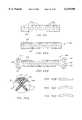
- FIG. 1is a perspective view of the first embodiment of a multiple locking plate.
- FIG. 2is a top plan view of the multiple locking plate shown in FIG. 1.
- FIG. 3is a side view of the multiple locking plate shown in FIG. 1.
- FIG. 4is an end view of the multiple locking plate shown in FIG. 1.
- FIG. 5is a bottom view of the multiple locking plate shown in FIG. 1.
- FIG. 6is a top view of the multiple locking plate shown in FIGS. 1-5, with locking elements installed, in an open configuration.
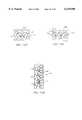
- FIG. 7is a top view of a modification of a plate of FIGS. 1-6 with a four bone screw locking element in place.
- FIG. 8is a top view of a further embodiment of the multiple locking plate of FIG. 1 with an elongated central slot for increased compression capability.
- FIG. 9is a locking element capable of use with the plates of FIGS. 1-6.
- FIG. 10is a top view of a locking element for use with the central opening of the plate of FIGS. 7 and 22.
- FIG. 11is a top view of a locking cap for use in the end openings shown in FIGS. 1, 6 and 7.
- FIG. 12is a side view of the locking element of FIG. 16.
- FIG. 13is a side view of another embodiment of the locking element of FIG. 16.
- FIG. 14is a perspective view of an alternative embodiment of cervical spine locking plate using locking rivets.
- FIG. 15is a bottom view of the multiple locking plate of FIG. 14.
- FIG. 16is a top view of a preinstallable two bone screw locking element.
- FIG. 17is a top view of an alternative embodiment of a four bone screw locking element having head slots for increased flexibility of the locking tabs.
- FIG. 18is a bottom view of the rivet type locking element for use with the central opening of the plate of FIG. 14.
- FIG. 19is a side view of a rivet locking element.
- FIG. 20is a top perspective view of the bottom portion of the head of rivet of FIG. 19 viewed along lines 20--20.
- FIG. 21is a top perspective view of the head portion of a three bone screw locking element.
- FIG. 22is a perspective view of a multiple locking plate formed to utilize locking elements in the form of threaded caps.
- FIG. 23is a side view of a locking element for use with the plate of FIG. 22.
- FIG. 24is a side view of a bone screw.
- FIG. 25is a side view of an alternative form of a bone screw.
- FIG. 26is a bottom view of the bone screws shown in FIG. 24.
- FIG. 27is a top view of the bone screw shown in FIG. 24.
- FIG. 28is a top perspective view of a fourth embodiment of a multiple locking plate.
- FIG. 29is a perspective view of locking element for use with the plate of FIG. 28.
- FIG. 30Ais a partial side sectional view of the plate of FIG. 28 along lines 30--30 with a bone screw in place.
- FIG. 30Bis an alternative embodiment of the bone screw of the present invention.
- FIGS. 31A-31Eillustrates top plan views of alternative embodiments of the multiple locking elements of the present invention.
- FIG. 32Ais an elevational, cross-sectional detail view of a portion of the bone forming device engaged to a portion of the plate of the present invention.
- FIG. 32Bis an alternative embodiment showing a cross-sectional view through the plate with a drill guide to guide a hole forming instrument.
- FIG. 32Cis an elevational, cross-sectional detail view of a portion of an alternative embodiment of a bone forming device engaged to a portion of the plate of the present invention.
- FIG. 32Dis a cross-sectional view along line 32D--32D of FIG. 32C.
- FIG. 33is a perspective view showing the locking of the bone screws to the plate.
- FIG. 34Ais a partial side sectional view of a shielded locking element attached to a driver instrument.
- FIG. 34Bis a partial side sectional view of an alternative embodiment of a locking element.
- FIG. 35is a partial side sectional view of another embodiment of the locking element.
- FIG. 36is a partial cross-sectional view showing a plate, locking element and bone screws along lines 36--36 of FIG. 33.
- FIG. 37is an enlarged portion of detail along line 37 of FIG. 36.
- FIG. 38is a side partial cross sectional view of a plate holder attached to a plate.
- FIG. 39Ais a side partial cross sectional view of another embodiment of a plate holder attached to a plate.
- FIG. 39Bis a side partial cross sectional view of another embodiment of a plate holder attached to a plate.
- FIG. 39Cis an end view of the plate holder shown in FIG. 39B.
- FIG. 39Dis an enlarged fragmentation view of the tip of the plate holder shown in FIG. 39B.
- FIG. 40is a top perspective view of an embodiment of a single locking plate.
- FIG. 41is a top plan view of the plate shown in FIG. 40.
- FIG. 42is a side view of the plate shown in FIG. 40.
- FIG. 43is an end view of the plate shown in FIG. 40.
- FIG. 44is a bottom plan view of the plate shown in FIG. 40.
- FIG. 45is a top plan view of the plate shown in FIG. 40, with locking elements in place.
- FIG. 46is a side view of a bone screw used with the plate shown in FIG. 40.
- FIG. 47is a top view of the bone screw shown in FIG. 46.
- FIG. 48is a bottom view of the bone screw of FIG. 46.
- FIG. 49is a top view of a locking cap for use with the single locking plate of FIG. 40.
- FIG. 50is a side view of the locking cap shown in FIG. 49.
- FIG. 51is a bottom view of the locking cap shown in FIGS. 49 and 50.
- FIG. 52is a bottom perspective view of the locking cap of FIGS. 49-51.
- FIG. 53is a cutaway view of the hole forming instrument threaded to a bone screw hole of a plate.
- FIG. 54is a perspective side sectional view of a drill and drill guide threadably engaged to the plate for drilling the hole for insertion of a bone screw.
- FIG. 55is a perspective view of a single locking plate installed along a bone with locking caps installed in two bone screw receiving holes.
- FIG. 56is a partial cross sectional view of a locking cap engaged to a driver for installing the locking cap.
- FIG. 57is a partial cross sectional view of the plate, bone screws and locking cap of FIG. 55.
- FIG. 58is an enlarged fragmentary view of area 58 of FIG. 57.
- FIG. 59is a perspective view of a second embodiment of a single locking plate having individual locking elements to lock each bone screw.
- FIG. 60is a perspective view of a threaded locking element for use with the single locking plate of FIG. 59.
- FIG. 61is a partial side sectional view of the plate of FIG. 59 viewed along lines 73--73 with the locking element of FIG. 60 in place to hold a bone screw, but not fully tightened.
- FIG. 62is a perspective view of an alternative locking element for use with a first modification of the single locking plate of FIG. 59.
- FIG. 63is a side sectional view of the first modification of the plate of FIG. 59 with the locking element of FIG. 62.
- FIG. 64is a perspective view of an alternative locking element for use with the first modification of the plate of FIG. 59.
- FIG. 65is a side sectional view of the first modification of the plate of FIG. 59 with the locking element of FIG. 64 in place.
- FIG. 66is a perspective view of another alternative locking element in the form of a rivet for use with a second modification of the locking plate of FIG. 59.
- FIG. 67is a partial side sectional detail view of the plate of FIG. 59 modified to use a locking element of FIG. 66 shown in place.
- FIG. 68is a top plan view of a single-lock plate.
- FIG. 69Ais a top plan view of plate of a single-lock the present invention having a staggered screw hole pattern to provide crossing over of the bone screws into bone.
- FIG. 69Bis an alternative embodiment of the plate shown in FIG. 69A.
- FIG. 70Ais cross sectional view of a bone with the plate of FIG. 69A or 69B engaged to the bone with two bone screws shown crossed over and penetrating the bone in different planes.
- FIGS. 70B-70Dare end views of alternative embodiments of the plate shown in FIG. 70A.
- FIG. 70Eis a side elevational view of a plate in accordance with the present invention shown applied to a long bone.
- FIG. 70Fis an enlarged detailed view along line 70F of FIG. 70E.
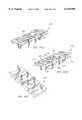
- FIG. 71is a top plan view of a further embodiment of the multiple locking plate for use in stabilizing multiple segments of the spine or portions of a long bone.
- FIGS. 72A-72Hare top plan view of various embodiments of multiple locking plates of the present invention.
- FIG. 73is a top plan view of an alternative embodiment of the present invention in the form of a multiple locking segmentable plate shown in a separated state.
- FIG. 74is a top plan view of an alternative embodiment of a multiple locking segmentable plate of FIG. 73 shown in a separated state.
- FIG. 75is a top plan view of an alternative embodiment of a multiple locking segmentable plate shown in an unseparated state.
- FIG. 76is a top plan view of an alternative embodiment of a multiple locking segmentable plate shown in an unseparated state.
- FIG. 77is a top plan view of a portion of an alternative embodiment of a multiple locking segmentable plate shown in an unseparated state.
- FIG. 78is a top plan view of an alternative embodiment of a multiple locking segmentable plate shown in an unseparated state.
- FIG. 79is a top plan view of the multiple locking segmentable plate of FIG. 78 shown in a separated state.
- FIG. 80is a top plan view of an alternative embodiment of the present invention in the form of a single-lock segmentable plate shown in an unseparated state.
- FIG. 81is a top plan view of the single-lock segmentable plate of FIG. 80 shown in a separated state.
- FIG. 82is a partial side sectional view of a passive dynamic screw-plate-lock system of the present invention.
- FIG. 83is a top plan view of an opening in the plate shown in FIG. 82.
- FIG. 84is a partial side sectional view of the passive dynamic screw-plate-lock system of FIG. 82 indicating motion in response to a force being applied to the screw in the direction of Arrow A.
- FIG. 85is a partial side sectional view of the self-compressing screw-plate-lock system of the present invention with the lock partially inserted.
- FIG. 86is a partial side sectional view of the self-compressing screw-plate-lock system of FIG. 85 in with the lock fully inserted and the screw seated.
- FIG. 87is a top plan view and opening in the plate shown in FIG. 86.
- FIG. 88is a side sectional view of the opening in the plate shown in FIG. 87.
- FIG. 89is a partial side sectional view of an active dynamic screw-plate-lock system of the present invention.
- FIG. 90is a top plan view of the opening in the plate shown in FIG. 89.
- FIG. 91is a top perspective view of the Belville type washer of the active dynamic screw-plate-lock system of FIG. 89.
- FIG. 92is a partial side sectional view of the active dynamic screw-plate-lock system of FIG. 82 with the lock further tightened and the screw seated.
- FIG. 93is a top perspective view of an alternative embodiment of the washer of FIG. 94 having a tab for insertion into a corresponding recess in the plate.
- FIG. 94is a partial side sectional view of the active dynamic screw-plate-lock system of FIG. 93 with the lock fully inserted, the screw seated, and the tab of the washer inserted into a corresponding recess in the plate.
- FIG. 95Ais a side perspective view of an alternative embodiment of a plate in accordance with the present invention.
- FIG. 95Bis a top perspective view of the plate in FIG. 95A.
- FIG. 95Cis a bottom perspective view of the plate in FIG. 95A.
- FIG. 96Ais a side perspective view of an alternative embodiment of a plate in accordance with the present invention.
- FIG. 96Bis a top perspective view of the plate in FIG. 96A.
- FIG. 96Cis a bottom perspective view of the plate in FIG. 96A.
- FIG. 97Ais a side perspective view of an alternative embodiment of a plate in accordance with the present invention.
- FIG. 97Bis a top perspective view of the plate in FIG. 97A.
- FIG. 97Cis a bottom perspective view of the plate in FIG. 97B.
- FIG. 97Dis a bottom plan view of the plate in FIG. 97B.
- a plurality of bone screwsare locked to a plate with a pre-installed locking element.
- Thisis referred to as the multiple locking plate system.
- the multiple locking plateswill be described, then the locking elements for locking the bone screws to the plate, and then novel bone screws for use with the plates of the present invention.
- a single locking elementlocks a single bone screw to the plate and is referred to as the single lock system.
- FIGS. 1-5The preferred embodiment of the multiple locking plate 2 according to the present invention is shown in FIGS. 1-5.
- Plate 2has a generally elongated form whose outline is generally rectangular. It is recognized that other shapes for plate 2 may be employed.
- Plate 2has a bottom surface 27 for placement against bone portions, wherein a substantial portion of bottom surface 27 is either flat and/or convex (as shown in FIGS. 95A-95C) along the longitudinal axis of the plate. Plate 2 is for general skeletal use other than in the anterior cervical spine.
- plate 2is provided with three locking screw holes 12, each of which in the preferred embodiment is internally threaded 3, and each of which is surrounded by a shallow countersunk region 14.
- bone screwsare inserted in the bone screw receiving holes and a single locking element associated with each of the locking screw holes 12 locks a number of bone screws 30 in position at one time.
- the locking elementmay be pre-installed to the plate.
- each end locking element 20will lock three bone screws 30 in place, while locking screw 21 in central locking hole 12 locks two bone screws 30 in place.
- central locking element 25can also be configured so that four bone screws 30 are locked at one time.
- Plate 2may have a thickness appropriate for the strength required for the bone or bones to which it is to be applied and generally in a range from 2 to 8 mm is preferred.
- bottom surface 27 of plate 2preferably has a porous, and/or textured surface and may be coated with, impregnated with, or comprise of fusion promoting substances (such as bone morphogenetic proteins) so as to encourage the growth of bone along the underside of plate 2 from bone portion to bone portion.
- the textured bottom surface 27also provides a medium for retaining fusion promoting substances with which the bottom surface 27 layer can be impregnated prior to installation.
- the bottom surface 27 of plate 2may be given the desired porous textured form by rough blasting or any other conventional technology, such as etching, plasma spraying, sintering, and casting for example.
- the bottom surface 27is formed to have a porosity or pore size in the order of 50-500 microns, and preferably 100-300 microns.
- Bone growth promoting substances with which the porous, textured bottom surface 27 can be impregnatedinclude, but are not limited to, bone morphogenetic proteins, hydroxyapatite, or hydroxyapatite tricalcium phosphate.
- the plate 2may comprise of at least in part a resorbable material which can further be impregnated with a bone growth material so that as the resorbable material is resorbed by the body of the patient, the bone growth material is released, thus acting as a time release mechanism.
- At least one end of plate 2may have a recess 18 that can cooperate with a compression apparatus.
- FIG. 6is a top plan view of plate 2 of FIG. 1 with locking elements 20, 21 inserted.
- the locking elementsare in the form of screws that cooperate with the threaded interior 3 of the locking holes 12.
- Each of these locking elements 20, 21is shown in its initial open orientation, where the orientation of the cutouts 22 in the head 23 of each locking element 20, 21 is oriented so as to permit introduction of bone screws 30 into adjacent bone screw receiving holes 6,8 without interference by the head 23 of the locking element 20, 21.
- FIG. 8is a top view of another embodiment of plate 2 of FIGS. 1-5, and is generally referred to as plate 120.
- Plate 120is provided with a longitudinally extending elongated slot 122 along its longitudinal axis which is superimposed on the middle locking hole 12.
- Elongated slot 122allows additional relative movement between plate 120 and a compression post 54 associated with a compression tool during a compression procedure.
- FIGS. 14 and 15an alternative embodiment of a multiple locking plate referred to by the number 70 is shown.
- plate 70rather than the threaded locking hole 12, a central opening 200 for receiving a removable rivet 202, of the type shown in FIGS. 17-20, is provided.
- FIG. 15is a bottom view of the plate 70 shown in FIG. 14. The contour of plate 70 is the same as that of plate 2 shown in FIGS. 1-5.
- the rivet 202is removable and fits within the unthreaded opening 200, comparable to the locking hole 12 and slot 122 described above.
- Other embodimentsmay employ a rivet that is not removable, but is manufactured as part of plate 70 as would be used in the end locking holes 19 of FIGS. 14 and 15.
- FIG. 22another alternative embodiment of a multiple locking plate is shown and is generally referred to by the number 230.
- the plate 230uses threaded caps, such as cap 300 shown in FIGS. 9 and 23, for a locking element or preferably one with cut outs as described herein having an appearance in a top view such as the locking screw element in FIGS. 10-11, for example.
- the central locking hole 602has an elongated slot 234 for providing an increased compression capability, if desired.
- FIG. 10is a top plan view illustrating the head 23 of the central locking element 25 shown in FIG. 7.
- the shaft 46 of locking element 25is threaded 47 to mate with the threading 3 within the associated locking hole 12 of plate 2.
- each segment 49 on each side of cutouts 22 of the locking element 21has a bearing surface 48 formed at the lower surface of locking element head 23.
- the locking element head 23can be provided with two slits 42 for providing flexibility to the locking element head 23 to assist in the locking element's ability to ride over the top of the bone screw head 32 during the locking action when the locking element is rotated.
- a ramp or wedge shaped surface 44may be used to increase the force applied to the bone screw head 32.
- cam design when lockedthe leading end of the ramped portion 44 of locking element 21 would be lower than the prominence of the bone screw head 32 so that more force is needed to lift the locking element 21 and untighten it than is needed for the locking element 21 to remain tight and locked.
- the locking element head 23need not have slits, be cammed or have a ramped surface to achieve the locking of bone screw 30 in place. Pressure, friction, interference fits, or other engagement means capable of preventing the locking element from moving from its locked position may be employed.
- Rivet 202intended for use in association with plate 70 of FIGS. 14-15, is shown and is also shown in detail in cross section in FIGS. 19 and 20.
- Rivet 202has a head 204, a shaft 206, and an elongated bottom segment 208 for fitting within the corresponding opening 200 in plate 70.
- the lower surface 210 of the head 204 of the rivet 202has a bearing surface, such as on the bottom of locking element 20, 21, for engaging the top surface 39 of the bone screw head 32.
- the upper surface of the elongated bottom segment 208can have a camming surface for cooperating with the camming surface 17 of the bottom of plate 70 to hold the rivet 202 in the locked position against the bone screw head 32, as shown in FIG. 15. While the rivet of FIG. 18 is a separate, removable component from the plate, the rivets, and particularly those for use with the end locking holes, can be formed as part of the plate during the manufacturing process of the plate and rivet can be non removable if so desired.
- the bearing surface of the rivet 202may also be cammed to prevent the rivet from unlocking once the cammed portion passes over the screw head.
- Each of the above embodimentsprovides tight attachment of the locking element relative the bone screw 30 and relevant plate.
- the locking elementcan be in the form of threaded locking cap 300 shown in FIG. 23.
- the threaded locking cap 300has a thread 302 on its outer circumference corresponding to the thread 303 on the inner circumference of the locking element depressions 304 in the top of plate 230 shown in FIG. 22.
- the locking cap 300is relatively thin, particularly compared to its width.
- the top 305 of locking cap 300may be provided with a noncircular recess or through hole 306 for receiving a similarly configured driving tool or employ other tool engaging means.
- Plate 400has an opening in its top surface for insertion of the thin locking member 412, a recess 402 associated with each of the bone screw receiving holes 408 and a slot 410 in the side wall of the bone screw receiving holes 408 to permit the thin locking member 412, having a series of thin projections or blades 414, thinner than the slot 410, that give this locking member 412 an appearance similar to that of a propeller.
- the thin locking member 412is able to be rotated within the plate so as to not cover the bone screw holes, thus allowing the thin locking member 412 to be pre-installed prior to the installation of the bone screws by the surgeon. Limited rotation of the thin locking member 412 allows the blades 414 to protrude through the slot 410 and to cover a portion of the top of the associated bone screws 30.
- the blades 414 of the thin locking member 412are flexible and, when rotated, slide over the top surface 39 of the bone screw head 32 to lock the bone screw 30 in place.
- each of the embodiments of the locking elementis capable of locking more than one bone screw 30. It is appreciated that the various multiple locking plates and locking element combinations are capable of locking as many as four bone screws at once, but are equally effective for locking a lesser number or none at all, that is securing itself to the plate.
- each of the above described locking element embodimentsis to have a driver engagement means, in these cases for example, a recess 24 as large as the recess 34 in the bone screws 30 so that the same tool can be used to turn both the bone screws 30 and the locking elements.
- the locking elementsare sufficiently strong and have sufficient mass so as to be able to withstand being locked without breakage.
- Bone screw 30'is a variable angle screw having a head 32' with a rounded top and has neck below the head 32' with relieved portions 33'a and 33'b to allow universal motion of the bone screw 30' within the bone screw receiving hole of a plate as the relieved portions provide clearance for the screw to move.
- bone screw 30'may be secured to the plate by a locking element that prevents the screw from backing out, but allows the locking element to bear down on the top of the screw head 32' still move relative to the plate.
- the bottom surface of the seat of the bone screw receiving hole and the bottom of the screw head 32'may be roughened to provide some resistance to movement of the screw head 32' within the bone screw receiving hole and/or the lock may bind the screw head with sufficient force such that once the lock is tightened no movement of the screw within the plate is possible.
- the multiple locking elementshave a number of cutout portions having an arc with a radius greater than that of the bone screw head.
- preinstallable multiple locking elementscan have a configuration without any cutout portions and still permit for clearance of the bone screw head.
- FIGS. 31A-31DSome examples of such locking elements are shown in FIGS. 31A-31D in which alternative embodiments of locking elements 20a-20d without cutout portions and in which the bone screws can be installed into the bone screw receiving hole 6 even when the locking element is pre-installed to the plate.
- the locking elementsmay be rotated in the direction of arrow A to bear upon at least a portion of the screw head to lock the bone screws to the plate.
- each locking element 20, 21is provided at its center with a noncircular recess 24, such as shown in FIG. 9 which is engageable by an appropriate manipulation tool, such as shown in FIGS. 33-35.
- the associated toolwould have a hex head, it is appreciated that other shapes of recesses in the head 23 may be used or other male or female driver engaging means may be used without departing from the scope of the present invention.
- the thread of each locking hole 12 and of each locking element 20, 21has a close tolerance so that they will reliably retain their orientations so as to permit introduction of bone screws 30 into bone screw receiving holes 6, 8 without interference. Alternatively, the threads can be slightly mismatched or a thread or threads can be made irregular or imperfect.
- FIG. 71an alternative multiple locking plate 990 is shown having additional intermediate bone screw receiving holes 980 and, associated locking elements 960 for locking the bone screws 30 in place.
- FIGS. 72A-72Hvarious plates 700a-h are shown. Each of these plates 700a-h have bone screws inserted through the bone screw receiving holes 6 and then locked in place. As shown in FIGS. 72A-72H, one locking element 710, or two locking elements can be used to lock four bone screws in place. In FIGS. 72A-72H, each of plates 700a-h is shown with the locking elements in their open orientation, before being rotated to lock the bone screws. Plates 700a-700h each have locking elements 710 for locking bone screws inserted into bone screw receiving hole 6 of the plate.
- FIG. 24provides a side view of one embodiment of a bone screw 30 according to the present invention.
- Bone screw 30has a bone screw head 32, a shaft 33, and a tip 36.
- FIG. 27is a top view of the bone screw 30.
- a profiled recess 34which may have the same form as the recess 24 of each locking element 20, 21 in which case it may be turned with the same tool as that employed for turning locking elements 20, 21. It is appreciated that the driver engaging portion of the bone screw 30 could be slotted, and be either male or female.
- the bone screw head 32is stepped, with the first lower head portion 35 being contiguous with the screw shank 33 and has a smaller diameter than the upper portion of the bone screw head 32.
- each bone screw receiving hole 6, 8 of plate 2has a countersunk region 14 matching the diameter of the upper portion of the bone screw head 32 and dimensioned for an interference fit.
- the lower portion 35 of the bone screw head 32is dimensioned to achieve an interference fit with its associated portion of bone screw receiving holes 6, 8.
- the larger diameter upper portion of bone screw head 32assures that the bone screw 30 cannot be advanced completely through bone screw receiving holes 6, 8 of plate 2.
- the bone screw 30passes completely through the upper surface of plate 2 without engaging the upper surface in any way.
- the head 32 of screw 30passes unobstructed through the upper surface of the plate until the lower surface of enlarged screw head 32 engages the upper face of the narrowed bone screw receiving portion at the midsubstance or below the midsubstance of the plate.
- Thisis considered optimal for allowing for the greatest screw to plate stability, even absent the lock, against all forces except those reverse the path of insertion, while still providing for the greatest plate strength beneath the bone screw head 23.
- a sheer vertical circumferential wallis best able to constrain the motion of a screw, if the head is similarly configured and there is little tolerance between them.
- Placing the support of the head near the mid thickness of the plateis preferred as it allows the upper head to remain large to accommodate the recess for the driver without being weakened, while placing the support of the head away from the upper surface of the plate allows the screw head to be deep into the plate. Placing the support of the head at approximately the mid thickness of the plate assures plenty of plate material beneath the head to support while providing adequate head length above and below the contact point to prevent the contact point from acting as a fulcrum by providing adequate lever arms to prevent unwanted motion.
- bone screw head 32'is tapered in the direction from the top of the bone screw head 32' toward screw tip 36'. Again, the bone screw head 32' is dimensioned to achieve an interference fit in the associated bone screw receiving hole 6, 8 when the bone screw 30' has been fully installed.
- bone screw receiving holes 6, 8need not be provided with a countersunk region 14.
- the bone screws 30 and 30'present a unique combination of a tapered screw shaft 33 and a helical thread 31.
- the diameter of screw shaft 33generally increases from a distal portion of the shaft near the screw tip 36 toward proximal portion of the shaft near screw head 32. In the preferred embodiment, the rate of increase in diameter is also greater near the bone screw head 32. Such a shape avoids stress risers and provides increased strength to the screw at the screw-plate junction, where it is needed the most.
- the tapering of screw shaft 33may have a concave form, as shown in FIG. 24, or may be linear. The distal portion of the screw shaft 33 may assume a constant diameter.
- the thread 31 of the bone screw 30has a substantially constant outer, or crest, diameter "d" from below the bone screw head 32 to near the bone screw tip 36.
- the crest diameter of thread 31may be reduced for preferably one to two turns to facilitate the insertion and penetration of the bone screw 30 into the bone.
- the thread 31 of each bone screw 30has an outer diameter slightly smaller than the diameter of the lowest portion 35 of the bone screw head 32, which is adjacent the trailing, or upper, end of the associated thread 31.
- the thread 31is relatively thin, in the direction of the longitudinal axis of the screw, and tapers outwardly, and has a cross section of a triangle, though the sides need not be straight.
- plate holder 870has a hollow tubular housing 872, with a central rod 874 having a thread 878 at one end for engaging one of the threaded locking holes 12 in plate 2.
- the bottom end of the housing 872has projections 880, 882 that extend outwardly and then downwardly to fit into the bone screw receiving holes 8 of plate 2 preventing the housing 872 from rotating.
- the central rod 874is located in the housing 872 such that it can be rotated by rotating a handle (not shown) which is fixed to the central rod 874 at its upper end.
- FIG. 39Aan alternative embodiment of the plate holder 890 is shown.
- a single solid member 890has a threaded projection 894 at its bottom end for attachment to the central threaded locking hole 12 in the plate.
- the bottom surface of the holder 890 of this embodimentis contoured so as to match the contours of the top surface of the plate adjacent to the locking hole 12, shown as a depression 14.
- Plate holder 890'has a hollow tubular housing 872' having a handle 891' at its top end and a bottom end 873' configured for insertion into a bone screw receiving holes 6 of a plate.
- a rod 874' having a sharp tip 875'is contained within housing 872' and is spring biased by a spring 875'.
- a lever 893'is provided for advancing rod 874' from within housing 872'.
- Lever 893'has a cammed portion 892' to lock rod 874' in position.
- the bottom end of the housing 872is slitted to form projections 880, 881, 882, and 883' that are moved outwardly by the shaft of rod 872' above tip 875' in the direction indicated by arrow A when rod 874' is advanced from within housing 872' to engage and lock into the bone screw receiving holes 6 of plate 2 preventing the housing 872' from separating from plate 2.
- the plate holder 890'functions as both a holder for a plate and also as a temporary plate fixation device to hold the plate in the correct position to the bone prior to the insertion of the bone screws. Further, holder 890' can be used to form pilot holes for screw insertion into the bone portions.
- FIG. 32ACertain structural features of hole forming apparatus 60 are shown in greater detail in FIG. 32A.
- the bottom end of housing 62has a projecting portion 69 dimensioned to fit precisely in a bone screw receiving hole 6 or 8 of plate 2.
- the bottom 71 of the projecting portion 69is flat in a plane perpendicular to the axis of housing 62.
- the lower end of the pilot hole forming apparatus 60is threaded so as to engage the thread in the bone screw receiving hole 6, 8 thereby fixing the plate and the pilot hole forming apparatus together, assuring a stable fit between the pilot hole forming apparatus and plate 2.
- the diameter of the leading end 66 of the shaft 64is small since it has to fit within the small space left between the inside wall of the pilot hole forming apparatus. Since it is only a pilot hole for a self tapping bone screw 30 that is being formed, the small diameter is satisfactory.
- a drill guide 80having a lower end as shown in FIG. 32B.
- the drill 80 guideconsists of a tubular member 82 and a small diameter lower end 84 which is dimensioned to achieve a precise interference fit in the associated bone screw receiving hole 6, 8 of plate 2.
- drill guide 80has an axial end surface in a plane perpendicular to the longitudinal axis of the drill guide 80 so that when the small diameter portion 84 is fitted into the bone screw receiving hole 6 and the surface surrounding the small diameter portion 84 is flush against the upper surface of plate 2, the axis of the drill guiding bore 86 in drill guide 80 will be precisely perpendicular to the upper and lower surfaces of the associated portion of plate 2.
- the bottom end of the drill guide 80can be threaded so as to engage to the threaded opening of plate 2.
- Hole forming apparatus 60'is similar to hole forming apparatus 60, except that it has a ball end 62' that fits within bone screw receiving hole 6. As shown in FIG. 32D, the ball end 62' may be oriented at any angle relative to the plate for angular hole formation into the bone. Hole forming apparatus 60' provides for variable angle preparation of the pilot holes for the bone screws relative to the plate.
- bone screws 30are threaded into the bone 50 while holding plate 2 firmly against the bone 50 with plate holder 800.
- FIG. 33is a perspective view showing plate 2 of FIGS. 1-5, at a stage of a surgical procedure when bone screws 30 have been fully installed in bones or pieces of the same bone, and locking screws 20, 21 have been rotated to lock three bone screws 30 in place; the left-hand locking screw 20 as viewed has been rotated through an angle of about 45° to lock three bone screws 30 in place and the central locking element 21 has been rotated through an angle of about 90° to lock two other bone screws 30 in place.
- one of the bearing surfaces 44 of each locking element 20, 21rests atop the screw head 32 of a respective bone screw 30.
- locking elements 20, 21are provided to the user almost fully tightened, but in the open position such that bone screws can be inserted. Full locking of the bone screw requires 90° or less of turning of the locking element and often 45° will suffice to lock the bone screws.
- Installation of the multilock locking element 300can also be performed with a tool 220 such as shown in FIGS. 34A and 35 having a suitably shaped tip 222 with a length corresponding to the depth of hole 306 in a locking cap 300.
- the end 222 of tool 220is flared just proximal to the most distal end so that it creates a friction fit with the screw cap 300 for ease of manipulation, and prevents the locking element 300 from falling off the tool 200.
- the tool receiving hole 306can be flared to cooperatively engage a tool having a tip with a corresponding configuration.
- FIG. 36is a cross-sectional view in the plane of the center of the two end locking screw holes 6 of plate 2, with two bone screws 30 in their installed positions and locking element 21 in its locking position.
- FIG. 37is an enlarged view of one of the bone screws 30 in plate 2 of FIG. 36.
- the axis of each screw 30is generally perpendicular to tangents to the upper and lower surfaces of plate 2 at points which are intersected by the longitudinal axis of the associated bone screw 30.
- bone screws 30can be directed so as to converge toward one another at a desired angle.
- the curvature of the plate from side to sidemay be so as to conform to the surface of the bone to which the plate is being applied and the axis of the paired screw hole may deviate from being perpendicular to the plate when viewed on end to achieve the optimal convergence.
- a "claw" of a rigid triangular frame structureis obtained at each pair of bone screws 30 such that the attachment of plate 2 to the bone would be highly secure due to the trapping of a wedged mass of bone material between the angled bone screws, even if any thread stripping should occur.
- the "claw”may be further formed by three angled bone screws in a tripod configuration or by four bone screws in a four sided claw configuration.
- FIGS. 40-45are views of a first embodiment of a single locking plate system generally referred to by the numeral 600.
- Plate 600has the same contour as plate 2 shown in FIGS. 1-5.
- Plate 600has a bottom surface 27 for placement against bone portions, wherein a substantial portion of bottom surface 27 is either flat and/or convex along the longitudinal axis of the plate though a lesser portion of bottom surface 27 may be otherwise configured.
- plate 600contains bone screw receiving holes 602 which are internally threaded 603 for receiving corresponding locking elements in the form of a locking cap 610, shown in FIGS. 49-52.
- the bone screw hole 602may have an outer diameter appropriate to the screw diameter appropriate to the bone(s) for which the plating system is to be applied.
- a bone screw of a diameter of 4.0 to 6.5 mmwould be used and generally the screw head would be slightly larger in diameter.
- the opening in the upper plate surface to receive the locking capwould be similar to generally 0.2 mm to 4.0 mm greater than the screw head size which could be 0.2 mm to 6 mm larger in diameter than the threaded shaft diameter of the bone screw of approximately 5 mm with a preferred range of 4-6 mm though possibly greater.
- Cap attaching means other than threadsmay be used, such as bayonet type attachment elements.
- each bone screw receiving hole 602 of plate 600has an inwardly stepped portion of properly selected dimensions for retaining an associated bone screw 170, as shown in FIGS. 46-48.
- the difference between the bone screw 170 used in the single locking embodiment of the plate from the bone screw used in association with the multiple locking plateis essentially due to the fact that whereas in the multiple locking plate embodiment the locking elements slide over a portion of the top 39 of the screw head 32 by a pressing, camming, or ramp action, in the single locking embodiment the locking cap 610 presses directly on the head 172 of the bone screw 170. Therefore, the head 172 of the bone screw 170 of the present embodiment need not be smooth.
- FIG. 55shows two bone screws 170 and associated threaded locking caps 610 in their fully installed positions. In these positions, head portions 174 and 176 of each bone screw 170 form an interference fit with corresponding portions of an associated bone screw receiving hole 602. Rim 612 of each threaded locking cap 610 forms an interference fit with upper portion 178 of the head of its associated bone screw 170. Because the thread 608 of each locking cap 610 mates precisely with the internal thread in an associated bone screw receiving hole 602, each threaded locking cap 610 is additionally subjected to a clamping force between associated head portion 178 and the internal threads 603 of associated bone screw receiving hole 602. Preferably the rounded head 614 of each threaded locking cap 610 assures that the upper surface of an assembled plating system will be free of sharp edges, or projections.
- FIG. 45is a top plan view of the plate 600 partially installed, with threaded locking caps 600 installed in bone screw receiving holes 602.
- FIGS. 47-49show a bone screw 170 for use with the single locking plating system according to the invention.
- Bone screw 170differs from bone screw 30 previously described in detail, only with regard to the stepped configuration of head 172.
- bone screw 170includes a lower portion 174 which is contiguous with the screw shank and has a reduced diameter equal to the maximum diameter of the shank 176.
- Portion 178 of head 172also has smaller diameter than lower portion 174.
- the thread 182has the same configuration as for the bone screw 30 discussed above. However, either embodiment of bone screws can be used with any of the plates.
- the bone screws 170 for use in the single locking plating systemare preferably solid, where the screws adjoin the lower plate surface, where as some screws used with prior art plates are hollow and are prone to breakage, the only recess in the heads of the present invention screws being for engagement of the tip 222 of driving tool 220 and with the recess being above the critical area of the lower plate surface screw junction. Therefore, these bone screws 170 remain robust.
- the screw headsare not deeply slitted into portions as per some prior art screws and the locking caps do not impose a radial outer force to expand the bone screw heads, so again the screw heads of the present invention are not spread apart and stressed and weakened, and so remain robust.
- variable angle screws 30' shown in FIG. 30Bmay be used in association with the single-lock plating system of the present invention.
- the plate 500may have any contour as any of the plates of the present invention appropriate for skeletal use and in which a substantial portion of the lower surface of the plate is either flat and/or convex (as shown in FIGS. 95A-95C) along the longitudinal axis of the plate.
- locking element 506may have a cutout portion with a radius greater than the radius of a bone screw head as is shown in connection with locking element 508 in FIG. 64.
- the heads 507 and 526 of the locking elements 508 and 522have a recess 510 and 524 corresponding to the radius of the bone screw openings 502 and 528 so that the locking element 508 and 522 may be installed in place prior to the insertion of the bone screw 170 into the bone screw receiving hole 502 and 528.
- the locking elements 508 and 522are rotated, a portion of its head extends over the top of the head of bone screw 170 to lock it in place.
- the bottom surface of the locking screws 508 and 522can have a ramped, cammed, or other configuration for engagement with at least a portion of the screw head.
- a locking plate 900is shown in which there are a number of bone screw receiving holes 950 along the longitudinal axis of plate 900.
- the close spacing and increased number of bone screw receiving holespermits the surgeon to locate appropriate holes to be aligned with each of the bone portions to be fixated, as well as allowing for more points of fixation to the bone.
- FIG. 69Aan alternative embodiment of the plate of the present invention is shown and generally referred to by the numeral 960.
- the plate 960has multiple bone screw receiving holes 970 passing through plate 960.
- the bone screw receiving holes 970are spaced apart in a staggered configuration such that the center point of each of the bone screw receiving holes 970 are on transverse lines that are offset from one another.
- the center point of the bone screw receiving holes 970are also offset from the midline of plate 970, but with less longitudinal distance between one another, while providing for sufficient distance between holes 970 to assure plate strength, than plate 900 shown in FIG. 68.
- plate 960is shown and generally referred to by the numeral 960'.
- Plate 960'has the same staggered pattern of bone screw holes 970 as plate 960 to permit crossing over of two bone screws 30.
- plate 960'has an overall configuration suitable for use in the spine including the anterior cervical spine.
- an embodimentcould have openings 910 in lobed portions at the corner of plate 960' and recesses 930 for use with a compressing apparatus.
- Plate 960could have additional pairs of lobes along the plate length. It is appreciated that the overall configuration of plate 960' can vary as can the offset pattern of the bone screw holes.
- the offset pattern of bone screw receiving holes 970permits longer bone screws 30 to be used than would otherwise be possible if the screws were aligned in transverse pairs without having bone screws 30 touch each other, due to the fact that the bone screws 30 are in different planes, and each bone screw 30 gets to travel a much longer diagonal path in crossing the sagittal midline, providing greater fixation.
- the shafts of two bone screws 30cross over in close proximity to each other and define an included angle IA preferably between 25 to 90 degrees.
- IApreferably between 25 to 90 degrees.
- FIGS. 70B-70Dend views of alternative embodiments of plate 960' are shown wherein the bottom surface of the plate may be in the transverse plane relatively flat, curved, or otherwise configured to fit the surface configuration of the bone or bones to which the plate is to be applied.
- plates 960'overall are generally shaped to conform to the bone(s) B to which they are applied.
- Segmentable plate 1000has an elongated body with a plurality of bone screw receiving holes 1010 spaced apart along a substantial portion of the length of the segmentable plate 1000.
- Segmentable plate 1000has a multiple locking system 1020 for locking bone screws to plate 1010 as described above in connection with multi-lock plate 2 shown in FIGS. 1-7.
- Plate 1000is preferably, but not limited to being made of a malleable material, such as titanium or one of its surgically acceptable alloys.
- Plate 1000comprises a plurality of segments 1030-1038 which can be separated from each other.
- a first segment 1030 of plate 1000is marked by a segmentation zone 1040 along which the plate may be separated to separate first segment 1030 from the remainder of plate 1000.
- Segmentation zone 1040can be any type of scoring which creates a place of least resistance along which when the plate 1000 is bent sufficiently to create a separation in the material of plate 1000, the separation will occur along the segmentation zone.
- segmentation zone 1040may be formed by removing approximately 0.25 mm to 0.5 mm of material in total from the upper surface, lower surface or both upper and low plate surfaces combined of the plate.
- the scoringcan be relatively thicker or thinner in width, variable in depth and of variable shape (e.g. "V" notched, rounded, etc.) to achieve the desired qualities.
- plate 1000is made of titanium, the inherent qualities of titanium are such that the plate may be separated simply by bending the plate sufficiently along segmentation zone 1040 while supporting the plate with appropriate plate holders to either side of segmentation zone 1040 and then bending the plate towards its original position at which time the plate will separate apart along the segmentation zone 1040, providing a sufficiently clean edge suitable for surgical use.
- a set of four segmentable plates 1000 to cover the various combinations required for application to one to four levels of the cervical spinewould include a first segmentable plate having a first segment with a spacing distance between the bone screw receiving holes of 10 mm, and subsequent segments similarly spaced at 10 mm intervals between the holes; a second segmentable plate having a first segment with a spacing distance between the bone screw receiving holes of 12.5 mm, and subsequent segments spaced at 12.5 mm intervals between the screw holes; a third segmentable plate having a first segment with a spacing distance between the bone screw receiving holes of 15 mm and subsequent segments spaced apart at 15 mm intervals between the holes; and a fourth segmentable plate having a first segment with a spacing distance between the bone screw receiving holes of 17.5 mm and subsequent segments spaced apart at 17.5 mm intervals between the holes
- the longitudinal spacing between the bone screw receiving holes 1010may be varied by changing the length of the portion of plate 1000 between bone screw receiving holes 1010 as illustrated by the dotted lines in FIG. 74.
- the described platesmay be separable into a multitude of usable portions, as would be desirable for manufacturing purposes and possibly for clinical use, because of regulatory issues involving the identification of each implant with a distinct and singular implant identification number for tracking purposes it may be desirable to configure the plates of the present invention such that each plate will yield only one usable portion.
- the segmentation zone 1040is made as shown in FIG. 79, such that the unused, separated pieces of the segmentable plates would not be usable as plates and would be discarded.
- the ability to separate a plate into segmentsalso provides significant advantages in the manufacturing process.
- the cost of the materialis not as significant as the labor involved in the manufacturing. Therefore, the manufacturer can cast one long segmentable plate which can then be separated in the later manufacturing stages to yield multiple plates at an overall lower cost.
- the platewere in the alternative to be manufactured by machining from solid stock, great labor could be saved by fixturing and securing a single long plate that is later separable into multiple plates rather than having to fixture and secure each of those plates individually.
- FIGS. 75-79various segmentable plates 1300-1700 are shown for application in reconstructive surgery.
- Plates 1300-1700have bone screw receiving holes 1310-1710, locking elements 1320-1720, and separation zones 1340-1740 respectively.
- the segmentable plates 1300-1700can be used to align and maintain the broken bone portions in correct spatial relationship.
- the curved characteristics of an eye socketwould require the plate used to repair the socket to match the curvature.
- the segmentable plates 1300-1700are made of a malleable metal, the malleability of which is enhanced by the segmentation of the plate, and can be easily contoured by the surgeon to the appropriate curvature.
- the correct length of the segmentable platecan also be easily be selected by the surgeon by separating the plate at the appropriate segment as described above in connection with plate 1000 shown in FIG. 73.
- the separation zonesallow the plate to be more easily bent, but without separating.
- the present inventionmakes a virtue of the material property of that alloy in that it may be bent without damage, but fails with surprisingly little force if first bent and then bent back. Back bending is therefore only done for plate separation and is not needed for contouring which requires only primary bending.
- segmentable plate 1800 and 1900alternative embodiments of the segmentable plate are shown and generally referred to by the numeral 1800 and 1900.
- Segmentable plates 1800-1900may be segmented at segmentation zones 1840 and 1940 as described above in connection with the multiple lock embodiment of the segmentation plate 1000.
- the passive dynamic system 2000is shown having a plate with a screw hole 2010 passing through the top and bottom surfaces of the plate 2020 for receiving a bone screw 2030.
- the screw hole 2010has a round opening 2040 at the top of the plate 2020 and an opening 2050 in the bottom of the plate that is in part coaxial with the top opening 2040, but extends in one direction to form an oblong.
- the rounded head 2032 of bone screw 2030is prevented from backing out of plate 2020 with a locking element 2060 that is engaged to plate 2020, while the shaft of bone screw 2030 is capable of angular motion in the direction of arrow A relative to plate 2020, since there is space in the oblong-shaped bottom opening 2040 of the screw hole 2010 for the shaft of the bone screw 2030 to travel in the one permitted direction relative to the plate 2020.
- the passive dynamic systemallows bone screw 2030 to move relative to plate 2020 even after being locked to plate when a force is presented against the screw. This system does not cause screw movement, but only allows for movement of the screw to occur and this is a "passive" system. Nevertheless, screw 2030 retains the ability to resist any unwanted motion in all other directions.
- the use of variable screw 30' as already describedmay also allow for passive dynamic action, but is not generally preferred as it does not limit the motion to but a single direction.
- a self-compressing system 2100comprising a plate 2120 having a bone screw receiving 2110 hole with a top opening 2140 that is preferably but not necessarily round, and having a rounded recessed portion 2142 is shown.
- the bone screw receiving holehas bottom opening 2150 that is smaller in diameter than the top opening 2140 and has a central longitudinal axis 2153 that is offset from the central longitudinal axis 2151 of the top opening 2140.
- the bone screwhas a rounded head portion 2132 which fits within the rounded bottom 2142 of the top opening 2140 and permits movement of the screw head 2132 within the top opening in order to provide the appropriate angle A of the bone screw shaft with respect to the plate 2120 as the bone screw shaft passes through the bottom opening 2150.
- the self-compressing systemAs the bone screw 2130 is being locked to the plate 2120 with a locking element 2160, the locking element 2160 puts pressure on the bone screw head 2132 to make the bone screw 2130 move in one direction. The bone screw 2130 cannot move back once it is locked to the plate 2120 by the locking element 2160.
- the purpose of the self-compressing system 2100is to provide a fixed and locked angle A on the bone screw 2130 for providing compression of bone portions.
- the active dynamic system 2200 of the present inventionis shown comprising a screw 2230 that is mounted to a plate 2220 under a spring loaded force, such as with a Belville type washer 2270 that applies a selected force to the screw 2230.
- the bone screw 2230will move in the direction of the force that is being applied as bottom opening 2250 of the bone screw receiving hole is oblong shaped.
- the big end 2272 of the spring formed by washer 2270bears down on the screw head 2232 away from the direction that the bone screw 2230 is to be moved.
- plate, screw, hole, and springit is simple to determine correct resistance, that being an amount less than would separate the bone.
- the washer 2270may also have a tab 2290 which fits into a recess 2292 formed within the top opening in order to facilitate proper orientation of the washer when placed within the opening or alternatively the washer 2270 may have a non-circular shape so as to not rotate when positioned.
- a pre-loaded forceis applied to a bone screw that keeps the screw in a certain orientation with respect to the plate.
- the bone screwwill only move further in the pre-oriented direction if there is space available and if there is no opposing force present to counteract the pre-loaded force on the screw.
- Plate 3000has a bottom surface 3027 that is convex along a substantial portion of the longitudinal axis of the plate and is concave along the transverse axis of the plate 3000.
- Plate 3000has a single-locking element 3022 for locking a single bone screw 3030 to plate 3000.
- Plate 3100has a bottom surface that is flat along a substantial portion of the longitudinal axis of the plate and is concave along the transverse axis of the plate.
- Plate 3100has a multiple locking element 3120 for locking two bone screws 3130 and single locking elements 3122 for locking individual bone screws 3130 to plate 3100.
- Bone screw receiving holes 3140are staggered such that the center point of each of the bone screw receiving holes 3142 and 3144 are on transverse lines that are offset from one another. The center point of the bone screw receiving holes 970 are also offset from the midline of plate.
- the shafts of two bone screws 30cross over in close proximity to each other and define an included angle IA between 25 to 90 degrees.
- Such a crossed configuration of bone screws 30provides an extremely stable engagement of plate 960 to the bone as they are very close together and diagonally crossed within the same bone, thus trapping an area of bone between them.
- Plate 3100comprises a plurality of segments 3150-3156 which can be separated from each other.
- a first segment 3150 of plate 3100is marked by segmentation zones 3160-3164 along which the plate may be separated to separate segments 3150, 3152, 3154, or 3156 from the remainder of plate 3100.
- Segmentation zones 3160-3164can be any type of scoring which creates a place of least resistance along which when the plate 3100 is bent sufficiently to create a separation in the material of plate 3100, the separation will occur along the segmentation zone.
- plate 3100may include one or more of the screw-lock-plating systems 2000, 2100, or 2200 described above in FIGS. 82-84.
- Plate 3200has a bottom surface that is flat along a substantial portion of the longitudinal axis of the plate and is concave along the transverse axis of the plate and has an upper surface that is concave along the transverse axis of the plate 3200.
- plate 3000may include one or more of the screw-lock-plating systems 2000, 2100, or 2200 described above in FIGS. 82-94.
Landscapes
- Health & Medical Sciences (AREA)
- Orthopedic Medicine & Surgery (AREA)
- Surgery (AREA)
- Life Sciences & Earth Sciences (AREA)
- Biomedical Technology (AREA)
- Public Health (AREA)
- Veterinary Medicine (AREA)
- Engineering & Computer Science (AREA)
- Nuclear Medicine, Radiotherapy & Molecular Imaging (AREA)
- Heart & Thoracic Surgery (AREA)
- Medical Informatics (AREA)
- Molecular Biology (AREA)
- Animal Behavior & Ethology (AREA)
- General Health & Medical Sciences (AREA)
- Neurology (AREA)
- Dentistry (AREA)
- Oral & Maxillofacial Surgery (AREA)
- Surgical Instruments (AREA)
- Prostheses (AREA)
Abstract
Description
This application claims priority of application Ser. No. 60/037,139 filed Feb. 11, 1997, incorporated herein by reference. Application Ser. No. 09/022,293, filed Feb. 11, 1998, and titled ANTERIOR CERVICAL PLATING SYSTEM, INSTRUMENTATION, AND METHOD OF INSTALLATION is incorporated by reference herein.
1. Field of the Invention
The present invention relates generally to skeletal plate systems for aligning and maintaining bone portions of the same bone or of different bones in a selected spatial relationship for healing or fusion of the bone portions, respectively. In particular, the present invention relates to skeletal plating systems comprising a plate that is flat and/or convex over a substantial portion of the lower surface of the plate along the longitudinal axis of the plate, bone screws, and locks for locking the bone screws to the plate; to segmentable plates; crossing screw plates; and combination bone screw-lock-plate systems permitting or causing, intersegmental bone compression and/or shortening.
2. Description of the Related Art
It is current practice in orthopedic surgery to use plating systems for joining portions of a broken bone, or for fusion of portions of separate bones. Such systems are composed essentially of plates and screws for aligning and holding the bone portions in a desired position relative to one another. Plating systems have usefulness in the spine, and have general skeletal use on the flat bones, such as the scapula and the pelvis by way of example, and for use on tubular bones, such as the humerus, ulna, radius, femur, and tibia by way of example.
Problems associated with such plating systems have included hardware breakage, hardware loosening, inability to gain adequate fixation, and distraction pseudoarthrosis where the plate will not allow the bone portions to come together over time resulting in a failure to get solid bone healing. These occurrences may cause problems, be associated with surgical failure, and require further surgical procedures to repair the damage, remove the failed hardware, and/or to reattempt skeletal stabilization.
Plates are usually provided to the surgeon for use in sets having a range of sizes so as to provide for such features as biological variability in size, the numbers of segments to be joined, and the length of the portions of bone to be joined. By way of example, it would be common for a plating system for use on the anterior cervical spine and for joining from two to five vertebrae to comprise of from forty to sixty plates. This requires manufacturers to make a large number of different plates, resulting in increased manufacturing costs and inventory costs and increased costs for hospitals to stock large numbers of plates. Further, in the event that a plate is used and another of its kind is needed before it can be replaced, the ability to provide to a patient the best care could be compromised.
Known plating systems additionally experience problems in connection with those procedures where bone grafts are placed between vertebral bodies to achieve an interbody fusion which heals by a process called "creeping substitution". In this process, dead bone at the interfaces between the graft and the adjacent vertebra is removed by the body, as a prelude to the new growth of bone forming cells and the deposition of new bone. While the plates allow for proper alignment of the vertebrae and their rigid fixation, they can therefore, at the same time unfortunately, hold the vertebrae apart while the resorption phase of the creeping substitution process forms gaps in the bone at the fusion site with the result that the desired fusion does not occur. Such failure in an attempted fusion is known as pseudoarthrosis. A similar phenomenon occurs at the interface of a fractured bone's fragments and is known as non-union. When such a failure occurs, the hardware itself will usually break or become loosened over time requiring further surgery to remove the broken hardware and to again attempt fusion or fracture repair.
Based on a consideration of the features of all of the known plating systems, there remains a need for an improved plating system having the following combination of features:
1) The plate and screws should be sufficiently strong to perform their intended function without mechanical failure;
2) The hardware, and specifically the screws, should be capable of achieving adequate purchase into the bone;
3) Means should be provided for locking each and every bone screw to the plate, and the locking means should be of sufficient size and strength to reliably perform its intended functions;
4) Bone screw locking means should preferably be retainable by the plate prior to bone screw insertion, or should be reliably attachable to a driver to prevent any small parts from becoming loose in the wound;
5) Bone screw orientation should be provided to create maximum screw purchase into bone and high resistance from being dislodged from the bone;
6) An improved and lower cost of production method for the manufacturer of medical plates should be provided;
7) A plate system should be provided for use in various sizes of patients which can be easily made to a selected length by a surgeon to fit the desired application in order to substantially reduce the number of plates required; and
8) Bone screw and plating system should be provided that prevent holding apart of bone portions during the process of creeping substitution and causes, or permits, or both causes and permits the bone portions to move toward each other to permit and promote the fusion or healing of the bone portions.
The present invention meets the above stated needs by providing various embodiments which are combinable, and may all be utilizable in the same plating system, such embodiments include (1) a skeletal plating system comprising a plate, that is flat over a substantial portion of its lower surface along the longitudinal axis of the plate and/or that has a lower surface that is convex curved along a substantial portion of the longitudinal axis of the plate, bone screws, and locks for locking the bone screws to the plate for skeletal use; (2) a skeletal plating system that permits a pair of bone screws to be inserted into a bone portion in a crossed over orientation and locked in place to the plate; (3) a segmentable skeletal plating system constructed so as to be selected for length by the surgeon; and (4) a combination screw-lock-plating system capable of allowing or urging bone portions together.
1. General Use Skeletal Plating-System
a. Multiple Lock System
The plating system of a first embodiment of the present invention comprises a general use skeletal plate having a bottom surface for placement against bone portions, wherein a substantial portion of the bottom surface of the plate is either flat or convex along the longitudinal axis of the plate. It is appreciated that a lesser portion of the lower surface of the plate may be otherwise shaped. The plate of the present invention has a plurality of bone screw receiving holes which extend through the plate, from the upper surface to the lower surface. The plate and its component parts, may be made of any implant quality material suitable for this purpose and suitable for use in the human body, such as, but not limited to, titanium or its alloys. The plate and/or the associated components may be made of a bioresorbable material and may comprise or be coated at least in part with fusion promoting chemical substances, such as bone morphogenetic proteins and the like.
Bone screws are each insertable into a respective bone screw receiving hole for attaching the plate to bone. A locking element, preferably, but not necessarily, in the form of a screw, is engageable in the locking screw hole of the plate and has a head formed to lock at least two of the bone screws to the plate. In the preferred embodiment, the locking elements are pre-installed prior to use by the surgeon in a manner so as to not impede installation of the bone screws into the bone screw receiving holes.
As a result, the problems previously associated with the locking screws of the type applied after the insertion of the bone screws, including the problems of instrumentation to position and deliver to the plate the locking means, backing out, breakage, stripping and misthreading associated with the prior art more delicate locking screws resembling "watchmaker's parts", are eliminated.
b. Single-lock System
The plating system of the second embodiment of the present invention comprises a single-lock plate for skeletal use having a bottom surface for placement against bone portions, wherein a substantial portion of the bottom surface of the plate is either flat or convex along the longitudinal axis of the plate. The single-lock plate has a locking element that fits within a bone screw receiving hole or into a recess overlapping a bone screw receiving hole to lock a respective one of the bone screws in place. According to this second embodiment of the invention, each of the bone screws is locked to the plate by means of an individual locking element which covers at least a portion of the bone screw. Since in the preferred embodiment of the single-lock plate, no other holes need be formed in the plate to attach the locking elements to the plate, the plate remains quite strong, or alternatively can be made thinner or narrower while keeping the requisite strength for the particular application.
The locking elements can be in many forms to achieve their intended purpose, such as, but not limited to, screws, threaded caps, rivets, set screws, projecting elements, and the like.
In common, neither the single-lock nor the multiple lock plating system requires that the head of the bone screw be hollow, as per some prior known plating systems. It will be appreciated that bone screws are weakened when their heads or head and neck portions are hollow so as to accommodate a second screw at least in part, if not wholly within.
2. Crossing Screw Plating System
In a further embodiment of the present invention, combinable in application with either the multiple lock or the single-lock systems and other novel features herein taught, a plate provides for the crossing over of the shafts of at least a pair of bone screws within a bone portion. A crossed orientation of the screws within the bone provides a more secure engagement of the plate to the bone to which it is to be applied because longer screws may be used and because an area of bone is wedged and trapped between the screws as compared to plates which do not allow paired screws to cross. The use of further screws crossed and/or not crossed in combination with the crossed screw pair can be utilized to trap a still larger section of bone. The plate of the present invention may have multiple bone screw receiving bores (with fixed central longitudinal axes) in which the bores are oriented in a staggered configuration, such that the center points of each of the paired bone screw hole receiving bores are on different transverse lines to permit at least a pair of bone screws to be inserted in a crossed-over configuration within a bone portion. Preferably, the screw bores have defined longitudinal axes in the transverse plane of the plate though the screws may be capable of a variation in positioning as will subsequently be described. In the preferred embodiment, the included angle formed by the shafts of the crossed screws is between 25 to 90 degrees. For spinal use, by way of example, the paired screws are staggered, but are still alignable within the same vertebra so as to be diagonally crossed within that same vertebra and preferably crossed within the posterior two thirds of the vertebral body.
3. Segmentable Plating System
In a further embodiment of the present invention a segmentable plating system is disclosed combinable with the multiple lock and single-lock plating system and the crossing screw teaching, as well as combinable with other novel features herein taught. The segmentable plating system provides a single plate, or a limited set of plates, for aligning and maintaining bone portions in selected spatial relationship in which the plates are manufactured so as to be strong in use, but separable into shorter lengths by the surgeon as needed, thereby eliminating the need to stock a multitude of plate lengths.
By way of example, for application in the spine, an embodiment of the segmentable plating system of the present invention comprises a plate that is capable of spanning multiple segments of a cervical spine and has predetermined separation zones. The separation zones may be positioned in a segmentable plate such that when a portion of the segmentable plate would be applied to the vertebrae, the remaining separation zones in the plate, if any, would be supported by an underlying vertebrae. In use, the surgeon would determine the appropriate plate length needed and if the length needed was less than the length of the provided plate, the surgeon would remove the unneeded portion of the plate at the appropriate separation zone. By way of example, this procedure may be easily performed when the plate is made of titanium or one of its alloys, as the properties of titanium are such that when the plate is bent and then returned to its original position, a clean separation is made at the bend. The parts of the segmentable plates that are being separated can be held to either side of the separation zone to ensure that a precise separation is effected. The separation zones of the segmentable plate, by way of example, may comprise of the plate being scored along its upper, lower, or both upper and lower surfaces. The depth of such scores being dependent on the thickness of the plate, and being sufficient to create surface notchings and a path of least resistance for the plate separation, and yet of limited depth and shape, so as to not weaken the plate so as to render it less than sufficiently strong for its intended use.
By way of example, for application to the anterior aspect of the cervical spine four segmentable plates each having generally a similar length for example sufficient to span five vertebrae (a length of from 80 to 120 mm), and each having different spacings between pairs of bone screw holes could comprise a complete set of plates allowing a surgeon to have all lengths and hole spacings needed to fuse from two to five vertebrae. While the described plates may be separable into a multitude of usable portions, because of regulatory issues involving the identification of each implant with a distinct and singular implant identification number for tracking purposes it may be desirable to configure the plates of the present invention such that each plate will yield only one usable portion, such as is taught in the present invention.
The segmentable plating system of the present invention also has application in reconstructive surgery. For example, during repair of a broken eye socket, the segmentable plating system of the present invention can be used to align and maintain the broken bone portions in correct spatial relationship. The curved characteristic of an eye socket would require the plate used to repair the socket to match the curvature. The segmentable plate of the present invention may be made of a malleable metal, with the malleability of the plate being enhanced by the segmentation of the plate, such that it can more easily be contoured by the surgeon to the appropriate curvature. The correct length of the segmentable plate can also be easily obtained by the surgeon as already described. It should be noted that if for example surgical titanium alloy is selected for the plate material, then the separation zones allow the plate to be more easily bent, but without separating. The present invention makes a virtue of the material property of that alloy in that it may be bent without damage, but fails with surprisingly little force if first bent and then bent back. Back bending is therefore only done for plate separation and is not needed for contouring which requires only primary bending.
The ability to separate a plate into segments also provides significant advantages in the manufacturing process. By way of example, in the process of investment casting, a process commonly used to produce plates. The investment casting cost of material is minor relative to the labor involved in the casting process for the production of each plate regardless of size. It is far more economical to cast one eight inch long plate, which is later separable into four two inch long plates, than to make four two inch castings. If machining is included in production, as from bare stock or stamping or casting, that work can be automated, but the placing of the piece into the machine and securing it (fixturing) generally requires hands on attention, is time consuming, and is a potential manufacturing bottleneck. An eight inch long plate yielding four two inch plates potentially separable at the end by the machine doing the machining, may be fixtured only once. In contrast, the prior art method of manufacturing would require each of the four two inch long plates to be fixtured separately, one at a time. Therefore, the manufacturer can cast one long segmentable plate which can then be separated in the later manufacturing stages to yield multiple plates at an overall lower cost. Similarly, if the plate were in the alternative to be manufactured by machining from solid stock, great labor could be saved by fixturing and securing a single long plate that is later separable into multiple plates rather than having to fixture and secure each of those plates individually.
4. Combination Screw-Lock-Plating System Capable of Intersegmentable Compression and Shortening
In a further alternative embodiment combinable with both the single-lock and multiple lock plate designs, the crossed screw teaching, and the segmentable plate teaching as well as other novel aspects of the present invention taught herein, three types of combination screw-lock-plate systems are taught, each capable of intersegmentable shortening and/or compression. Each of the taught systems is designed to counteract and compensate for the lack of contact between bone portions to be joined that may occur as a result of creeping substitution described above. The present invention will allow the vertebrae to move toward an interposed bone graft, and each other if necessary, instead of keeping the vertebrae apart during the occurrence of the resorption phase of the creeping substitution process. Unlike prior art "dynamic" and/or compression plating systems, the present invention may allow for the preservation and/or enhancement of lordosis while otherwise restricting the motion of the bone screws relative to the plate.
The three types of screw-plate-lock systems, which are themselves combinable with one another, are as follows: (1) Passive Dynamic; (2) Self-Compressing; and (3) Active Dynamic and are described below.
a. Locked Passive Dynamic Plating System
As used in this description, the term "locked" means the screws are locked to the plate and can not backout. The term "dynamic" means the screw is capable of movement even though it is locked within the plate to allow bone portions to move closer together. The term "passive" means motion of the screw relative to the plate is allowed, but not caused.
The passive dynamic system allows a bone screw to move relative to the plate even after being locked to the plate when a force is presented against the screw. This system does not cause screw movement, but only allows for movement of the screw to occur and thus is a "passive" system. In a preferred embodiment, motion of the screw relative to the plate is confined to but one direction, that direction permitting bone portions to move closer to one another along the longitudinal axis of the plate.
In the passive dynamic system, a plate having a screw hole passing through the top and bottom surfaces of the plate for receiving a bone screw, may have a round opening at the top of the plate and may have a bottom opening that is oblong-shaped with a length greater than the diameter of a bone screw shaft locatable the screw hole when in use. The head of the bone screw is secured to the plate against backing out and generally against significant linear motion with a locking element, while the shaft of the bone screw is capable of angular motion relative to the plate. The oblong-shaped bottom opening of the screw hole allows the shaft of the bone screw to travel relative to the plate while the bone screw head rotates. The movement of the screw is greatest at the distal end of the screw, allowing for differential shortening of the bone portions being joined. For example, if such a plating system is applied to the anterior aspect of the cervical spine, lordosis (a convex curvature forward of the aligned vertebrae of the neck when viewed from the side) is enhanced when said passive movement occurs.
b. Self-Compressing Locking Plate System
In the self-compressing system, as a bone screw undergoes final tightening, or as it is being locked to the plate with a locking element the bone screw is forced to move in one allowed and desired direction. The bone screw can not move back once it is locked to the plate by the locking element. A purpose of the self-compressing system is to provide a fixed and locked angle of the bone screw relative to the plate for providing compression of bone portions to be joined, such as for example the cervical vertebrae adjacent a disc space, with movement of the bone screw as it is seated to the plate, producing compression and lordosis.
Unlike prior screw systems, the screws are only allowed to move in one direction, that being the direction that would bring bone portions to be joined closer together by angular motion, rather than to produce translational motion of a screw as a whole, without angular change. This induction of a compressive load across bone portions to be joined or fused, induces bone growth and when bone resorption occurs at the interface of the bone portions to be joined, those bone portions are urged to move closer together, thus avoiding the formation of a gap so as to mitigate against non-union or pseudoarthrosis.
The self-compressing system may comprise a plate having a bone screw receiving hole passing through the top and bottom surfaces of the plate with a top opening that is round and has a rounded seat. The bone screw receiving hole has bottom opening that has a central longitudinal axis that is offset from the central longitudinal axis of the top opening. The bone screw may have a partially rounded head which fits within the upper portion of the bone screw opening and permits movement of the screw head within the top opening in order to provide the appropriate angle for the bone screw shaft with respect to the plate as the bone screw shaft passes through the bottom opening.
Further it is known in the art that compressive forces across the bone further induce bone growth and formation and the present invention teaches novel ways of maintaining bone to bone contact, compressive loading, and even a means for enhancing and increasing the compressive load. A further benefit of the present invention can be appreciated by way of example in regard to use of the present invention on the anterior cervical spine for spinal fusion.
c. Active Dynamic Locking Plating System
In the active dynamic system, a pre-load force is applied to a bone screw such that while the screw may undergo no added motion initially, there is a selective force applied to the screwhead and the screw is capable of motion in only one direction, such that should resorption occur at the interfaces of the bone portions to be joined then the screw is not only free to move in that, and only that direction, but is also urged to do so as it moves to relieve the preload force. Features of these systems may be combined with each other.
By way of example only and not limitation, a plating system may utilize bone screw holes that have a lower surface opening that is oblong and extends from the center aligned to the longitudinal axis of the bone screw receiving bore in a direction for which screw motion is desired. A loading means such as a Bellville washer, lock washer, or other springing means is employed to bear upon the screw head when the screw is locked within the plate from backing out. Such a system urges the bone portions together over time as resorption permits.
For any given use, (plate, screw, hole, and spring) it is simple to determine correct resistance, that being an amount less than would break the bone to which the force is being applied. The Belville-type washer can have a tab which fits into a recess formed within the top opening of the screw hole in order to facilitate proper orientation of the washer or the washer or spring means can be other than round so as to be directionally orientable when placed within the top opening of the screw hole.
When features of these self compressing and active dynamic systems are combined, such a system forces bone portions close upon tightening and then both allows and urges such further motion, as resorption permits over time. The bone screw will only move further in the pre-oriented direction if there is space available and if there is an opposing force present less than the pre-loaded force on the screw.
It is an object of the present invention to provide an improved plating system which has the above described features and which avoids many of the shortcomings of previously known systems.
It is another object of the present invention to provide a locking mechanism where a plurality of bone screws used for attaching a plate to a bone portion can be easily and reliably locked in place at the same time by a single operation, and wherein the locking mechanisms for locking the bone screws may be pre-installed by the manufacturer prior to the insertion of the bone screws by the physician so that the physician does not have to attach the locking mechanism to the plate as a separate procedure during the operation.
A further object of the invention is to provide plates which are textured or otherwise treated to promote bone growth beneath the plate.
Yet another object of the invention is to provide a system in which the bone screws and locking mechanisms, when fully installed, have a low profile.
It is another object of the present invention to provide for a plating system which may be at least in part bioresorbable.
It is another object of the present invention to provide for a plating system comprising at least in part of bone ingrowth materials and surfaces.
It is another object of the present invention to provide for a plating system comprising at least in part of bone growth promoting substances.
It is another object of the present invention to provide plates with an improved holding ability within the bone due to a locked screw to plate crossover configuration.
It is another object of the present invention to provide a locked plating system capable of selected and specific screw motion so as to accommodate shortening of the bones to be joined.
It is another object of the present invention is to provide means for preventing distraction pseudoarthrosis of the anterior cervical spine, while providing for cervical lordosis.
The above and other objects and features of the invention will become more readily apparent from the following description of preferred embodiments of the invention, provided with reference to the accompanying drawings, which illustrate embodiments of the invention solely by way of non-limiting example.
FIG. 1 is a perspective view of the first embodiment of a multiple locking plate.
FIG. 2 is a top plan view of the multiple locking plate shown in FIG. 1.
FIG. 3 is a side view of the multiple locking plate shown in FIG. 1.
FIG. 4 is an end view of the multiple locking plate shown in FIG. 1.
FIG. 5 is a bottom view of the multiple locking plate shown in FIG. 1.
FIG. 6 is a top view of the multiple locking plate shown in FIGS. 1-5, with locking elements installed, in an open configuration.
FIG. 7 is a top view of a modification of a plate of FIGS. 1-6 with a four bone screw locking element in place.
FIG. 8 is a top view of a further embodiment of the multiple locking plate of FIG. 1 with an elongated central slot for increased compression capability.
FIG. 9 is a locking element capable of use with the plates of FIGS. 1-6.
FIG. 10 is a top view of a locking element for use with the central opening of the plate of FIGS. 7 and 22.
FIG. 11 is a top view of a locking cap for use in the end openings shown in FIGS. 1, 6 and 7.
FIG. 12 is a side view of the locking element of FIG. 16.
FIG. 13 is a side view of another embodiment of the locking element of FIG. 16.
FIG. 14 is a perspective view of an alternative embodiment of cervical spine locking plate using locking rivets.
FIG. 15 is a bottom view of the multiple locking plate of FIG. 14.
FIG. 16 is a top view of a preinstallable two bone screw locking element.
FIG. 17 is a top view of an alternative embodiment of a four bone screw locking element having head slots for increased flexibility of the locking tabs.
FIG. 18 is a bottom view of the rivet type locking element for use with the central opening of the plate of FIG. 14.
FIG. 19 is a side view of a rivet locking element.
FIG. 20 is a top perspective view of the bottom portion of the head of rivet of FIG. 19 viewed alonglines 20--20.
FIG. 21 is a top perspective view of the head portion of a three bone screw locking element.
FIG. 22 is a perspective view of a multiple locking plate formed to utilize locking elements in the form of threaded caps.
FIG. 23 is a side view of a locking element for use with the plate of FIG. 22.
FIG. 24 is a side view of a bone screw.
FIG. 25 is a side view of an alternative form of a bone screw.
FIG. 26 is a bottom view of the bone screws shown in FIG. 24.
FIG. 27 is a top view of the bone screw shown in FIG. 24.
FIG. 28 is a top perspective view of a fourth embodiment of a multiple locking plate.
FIG. 29 is a perspective view of locking element for use with the plate of FIG. 28.
FIG. 30A is a partial side sectional view of the plate of FIG. 28 alonglines 30--30 with a bone screw in place.
FIG. 30B is an alternative embodiment of the bone screw of the present invention.
FIGS. 31A-31E illustrates top plan views of alternative embodiments of the multiple locking elements of the present invention.
FIG. 32A is an elevational, cross-sectional detail view of a portion of the bone forming device engaged to a portion of the plate of the present invention.
FIG. 32B is an alternative embodiment showing a cross-sectional view through the plate with a drill guide to guide a hole forming instrument.
FIG. 32C is an elevational, cross-sectional detail view of a portion of an alternative embodiment of a bone forming device engaged to a portion of the plate of the present invention.
FIG. 32D is a cross-sectional view alongline 32D--32D of FIG. 32C.
FIG. 33 is a perspective view showing the locking of the bone screws to the plate.
FIG. 34A is a partial side sectional view of a shielded locking element attached to a driver instrument.
FIG. 34B is a partial side sectional view of an alternative embodiment of a locking element.
FIG. 35 is a partial side sectional view of another embodiment of the locking element.
FIG. 36 is a partial cross-sectional view showing a plate, locking element and bone screws alonglines 36--36 of FIG. 33.
FIG. 37 is an enlarged portion of detail alongline 37 of FIG. 36.
FIG. 38 is a side partial cross sectional view of a plate holder attached to a plate.
FIG. 39A is a side partial cross sectional view of another embodiment of a plate holder attached to a plate.
FIG. 39B is a side partial cross sectional view of another embodiment of a plate holder attached to a plate.
FIG. 39C is an end view of the plate holder shown in FIG. 39B.
FIG. 39D is an enlarged fragmentation view of the tip of the plate holder shown in FIG. 39B.
FIG. 40 is a top perspective view of an embodiment of a single locking plate.
FIG. 41 is a top plan view of the plate shown in FIG. 40.
FIG. 42 is a side view of the plate shown in FIG. 40.
FIG. 43 is an end view of the plate shown in FIG. 40.
FIG. 44 is a bottom plan view of the plate shown in FIG. 40.
FIG. 45 is a top plan view of the plate shown in FIG. 40, with locking elements in place.
FIG. 46 is a side view of a bone screw used with the plate shown in FIG. 40.
FIG. 47 is a top view of the bone screw shown in FIG. 46.
FIG. 48 is a bottom view of the bone screw of FIG. 46.
FIG. 49 is a top view of a locking cap for use with the single locking plate of FIG. 40.
FIG. 50 is a side view of the locking cap shown in FIG. 49.
FIG. 51 is a bottom view of the locking cap shown in FIGS. 49 and 50.
FIG. 52 is a bottom perspective view of the locking cap of FIGS. 49-51.
FIG. 53 is a cutaway view of the hole forming instrument threaded to a bone screw hole of a plate.
FIG. 54 is a perspective side sectional view of a drill and drill guide threadably engaged to the plate for drilling the hole for insertion of a bone screw.
FIG. 55 is a perspective view of a single locking plate installed along a bone with locking caps installed in two bone screw receiving holes.
FIG. 56 is a partial cross sectional view of a locking cap engaged to a driver for installing the locking cap.
FIG. 57 is a partial cross sectional view of the plate, bone screws and locking cap of FIG. 55.
FIG. 58 is an enlarged fragmentary view ofarea 58 of FIG. 57.
FIG. 59 is a perspective view of a second embodiment of a single locking plate having individual locking elements to lock each bone screw.
FIG. 60 is a perspective view of a threaded locking element for use with the single locking plate of FIG. 59.
FIG. 61 is a partial side sectional view of the plate of FIG. 59 viewed along lines 73--73 with the locking element of FIG. 60 in place to hold a bone screw, but not fully tightened.
FIG. 62 is a perspective view of an alternative locking element for use with a first modification of the single locking plate of FIG. 59.
FIG. 63 is a side sectional view of the first modification of the plate of FIG. 59 with the locking element of FIG. 62.
FIG. 64 is a perspective view of an alternative locking element for use with the first modification of the plate of FIG. 59.
FIG. 65 is a side sectional view of the first modification of the plate of FIG. 59 with the locking element of FIG. 64 in place.
FIG. 66 is a perspective view of another alternative locking element in the form of a rivet for use with a second modification of the locking plate of FIG. 59.
FIG. 67 is a partial side sectional detail view of the plate of FIG. 59 modified to use a locking element of FIG. 66 shown in place.
FIG. 68 is a top plan view of a single-lock plate.
FIG. 69A is a top plan view of plate of a single-lock the present invention having a staggered screw hole pattern to provide crossing over of the bone screws into bone.
FIG. 69B is an alternative embodiment of the plate shown in FIG. 69A.
FIG. 70A is cross sectional view of a bone with the plate of FIG. 69A or 69B engaged to the bone with two bone screws shown crossed over and penetrating the bone in different planes.
FIGS. 70B-70D are end views of alternative embodiments of the plate shown in FIG. 70A.
FIG. 70E is a side elevational view of a plate in accordance with the present invention shown applied to a long bone.
FIG. 70F is an enlarged detailed view alongline 70F of FIG. 70E.
FIG. 71 is a top plan view of a further embodiment of the multiple locking plate for use in stabilizing multiple segments of the spine or portions of a long bone.
FIGS. 72A-72H are top plan view of various embodiments of multiple locking plates of the present invention.
FIG. 73 is a top plan view of an alternative embodiment of the present invention in the form of a multiple locking segmentable plate shown in a separated state.
FIG. 74 is a top plan view of an alternative embodiment of a multiple locking segmentable plate of FIG. 73 shown in a separated state.
FIG. 75 is a top plan view of an alternative embodiment of a multiple locking segmentable plate shown in an unseparated state.
FIG. 76 is a top plan view of an alternative embodiment of a multiple locking segmentable plate shown in an unseparated state.
FIG. 77 is a top plan view of a portion of an alternative embodiment of a multiple locking segmentable plate shown in an unseparated state.
FIG. 78 is a top plan view of an alternative embodiment of a multiple locking segmentable plate shown in an unseparated state.
FIG. 79 is a top plan view of the multiple locking segmentable plate of FIG. 78 shown in a separated state.
FIG. 80 is a top plan view of an alternative embodiment of the present invention in the form of a single-lock segmentable plate shown in an unseparated state.
FIG. 81 is a top plan view of the single-lock segmentable plate of FIG. 80 shown in a separated state.
FIG. 82 is a partial side sectional view of a passive dynamic screw-plate-lock system of the present invention.
FIG. 83 is a top plan view of an opening in the plate shown in FIG. 82.
FIG. 84 is a partial side sectional view of the passive dynamic screw-plate-lock system of FIG. 82 indicating motion in response to a force being applied to the screw in the direction of Arrow A.
FIG. 85 is a partial side sectional view of the self-compressing screw-plate-lock system of the present invention with the lock partially inserted.
FIG. 86 is a partial side sectional view of the self-compressing screw-plate-lock system of FIG. 85 in with the lock fully inserted and the screw seated.
FIG. 87 is a top plan view and opening in the plate shown in FIG. 86.
FIG. 88 is a side sectional view of the opening in the plate shown in FIG. 87.
FIG. 89 is a partial side sectional view of an active dynamic screw-plate-lock system of the present invention.
FIG. 90 is a top plan view of the opening in the plate shown in FIG. 89.
FIG. 91 is a top perspective view of the Belville type washer of the active dynamic screw-plate-lock system of FIG. 89.
FIG. 92 is a partial side sectional view of the active dynamic screw-plate-lock system of FIG. 82 with the lock further tightened and the screw seated.
FIG. 93 is a top perspective view of an alternative embodiment of the washer of FIG. 94 having a tab for insertion into a corresponding recess in the plate.
FIG. 94 is a partial side sectional view of the active dynamic screw-plate-lock system of FIG. 93 with the lock fully inserted, the screw seated, and the tab of the washer inserted into a corresponding recess in the plate.
FIG. 95A is a side perspective view of an alternative embodiment of a plate in accordance with the present invention.
FIG. 95B is a top perspective view of the plate in FIG. 95A.
FIG. 95C is a bottom perspective view of the plate in FIG. 95A.
FIG. 96A is a side perspective view of an alternative embodiment of a plate in accordance with the present invention.
FIG. 96B is a top perspective view of the plate in FIG. 96A.
FIG. 96C is a bottom perspective view of the plate in FIG. 96A.
FIG. 97A is a side perspective view of an alternative embodiment of a plate in accordance with the present invention.
FIG. 97B is a top perspective view of the plate in FIG. 97A.
FIG. 97C is a bottom perspective view of the plate in FIG. 97B.
FIG. 97D is a bottom plan view of the plate in FIG. 97B.
In a first embodiment of the present invention a plurality of bone screws are locked to a plate with a pre-installed locking element. This is referred to as the multiple locking plate system. The multiple locking plates will be described, then the locking elements for locking the bone screws to the plate, and then novel bone screws for use with the plates of the present invention. In an alternative embodiment, a single locking element locks a single bone screw to the plate and is referred to as the single lock system.
It is appreciated that the features associated with each of the embodiments of the present invention are not limited to the particular embodiment for which the features are described and are combinable with features described in association with all the embodiments of the present invention.
1. General Use Skeletal Plating-System
a. Multiple Locking Plate System
The preferred embodiment of themultiple locking plate 2 according to the present invention is shown in FIGS. 1-5.Plate 2 has a generally elongated form whose outline is generally rectangular. It is recognized that other shapes forplate 2 may be employed.Plate 2 has abottom surface 27 for placement against bone portions, wherein a substantial portion ofbottom surface 27 is either flat and/or convex (as shown in FIGS. 95A-95C) along the longitudinal axis of the plate.Plate 2 is for general skeletal use other than in the anterior cervical spine.
As an example only,plate 2 is provided with three locking screw holes 12, each of which in the preferred embodiment is internally threaded 3, and each of which is surrounded by a shallow countersunkregion 14. As will be described in greater detail below, in the preferred embodiment, bone screws are inserted in the bone screw receiving holes and a single locking element associated with each of the locking screw holes 12 locks a number of bone screws 30 in position at one time. The locking element may be pre-installed to the plate.
In the embodiment illustrated in FIGS. 1-5, eachend locking element 20 will lock threebone screws 30 in place, while lockingscrew 21 incentral locking hole 12 locks twobone screws 30 in place. As shown in FIG. 7,central locking element 25 can also be configured so that fourbone screws 30 are locked at one time.Plate 2 may have a thickness appropriate for the strength required for the bone or bones to which it is to be applied and generally in a range from 2 to 8 mm is preferred.
As shown in FIG. 5, at least a portion ofbottom surface 27 ofplate 2, preferably has a porous, and/or textured surface and may be coated with, impregnated with, or comprise of fusion promoting substances (such as bone morphogenetic proteins) so as to encourage the growth of bone along the underside ofplate 2 from bone portion to bone portion. Thetextured bottom surface 27 also provides a medium for retaining fusion promoting substances with which thebottom surface 27 layer can be impregnated prior to installation. Thebottom surface 27 ofplate 2 may be given the desired porous textured form by rough blasting or any other conventional technology, such as etching, plasma spraying, sintering, and casting for example. If porous so as to promote bone ingrowth, thebottom surface 27 is formed to have a porosity or pore size in the order of 50-500 microns, and preferably 100-300 microns. Bone growth promoting substances with which the porous,textured bottom surface 27 can be impregnated include, but are not limited to, bone morphogenetic proteins, hydroxyapatite, or hydroxyapatite tricalcium phosphate. Theplate 2 may comprise of at least in part a resorbable material which can further be impregnated with a bone growth material so that as the resorbable material is resorbed by the body of the patient, the bone growth material is released, thus acting as a time release mechanism. By havingplate 2 itself made from a material that is resorbable and by having bone growth promoting material present permits the bone portions to be joined to do so in a more natural manner as the plate becomes progressively less load bearing thereby avoiding late stress shielding of that bone area.
As further shown in FIGS. 4 and 5, at least one end ofplate 2 may have arecess 18 that can cooperate with a compression apparatus.
FIG. 6 is a top plan view ofplate 2 of FIG. 1 with lockingelements interior 3 of the locking holes 12. Each of these lockingelements cutouts 22 in thehead 23 of each lockingelement screw receiving holes head 23 of the lockingelement
FIG. 8 is a top view of another embodiment ofplate 2 of FIGS. 1-5, and is generally referred to asplate 120.Plate 120 is provided with a longitudinally extendingelongated slot 122 along its longitudinal axis which is superimposed on themiddle locking hole 12.Elongated slot 122 allows additional relative movement betweenplate 120 and a compression post 54 associated with a compression tool during a compression procedure.
Referring to FIGS. 14 and 15, an alternative embodiment of a multiple locking plate referred to by thenumber 70 is shown. Inplate 70, rather than the threadedlocking hole 12, acentral opening 200 for receiving aremovable rivet 202, of the type shown in FIGS. 17-20, is provided. FIG. 15 is a bottom view of theplate 70 shown in FIG. 14. The contour ofplate 70 is the same as that ofplate 2 shown in FIGS. 1-5. Therivet 202 is removable and fits within the unthreadedopening 200, comparable to the lockinghole 12 andslot 122 described above. Other embodiments may employ a rivet that is not removable, but is manufactured as part ofplate 70 as would be used in the end locking holes 19 of FIGS. 14 and 15.
Referring to FIG. 22, another alternative embodiment of a multiple locking plate is shown and is generally referred to by thenumber 230. Theplate 230 uses threaded caps, such ascap 300 shown in FIGS. 9 and 23, for a locking element or preferably one with cut outs as described herein having an appearance in a top view such as the locking screw element in FIGS. 10-11, for example. Thecentral locking hole 602 has an elongatedslot 234 for providing an increased compression capability, if desired.
Referring to FIGS. 10-13, a first embodiment of lockingelements plate 2 are shown. FIG. 10 is a top plan view illustrating thehead 23 of thecentral locking element 25 shown in FIG. 7. Theshaft 46 of lockingelement 25 is threaded 47 to mate with the threading 3 within the associated lockinghole 12 ofplate 2. As shown in FIG. 21, eachsegment 49 on each side ofcutouts 22 of the lockingelement 21 has a bearing surface 48 formed at the lower surface of lockingelement head 23. As shown in FIG. 16, the lockingelement head 23 can be provided with twoslits 42 for providing flexibility to thelocking element head 23 to assist in the locking element's ability to ride over the top of thebone screw head 32 during the locking action when the locking element is rotated.
Referring to FIGS. 6 and 10-13, it will be appreciated that when the lockingelements top surface 39 of a respectivebone screw head 32 in order to positively lock the associated bone screws 30 and thelocking elements elements
Alternatively, as shown in FIGS. 12 and 13, in place of a flat bearing surface 48, a ramp or wedge shapedsurface 44 may be used to increase the force applied to thebone screw head 32. In an alternative embodiment cam design when locked, the leading end of the rampedportion 44 of lockingelement 21 would be lower than the prominence of thebone screw head 32 so that more force is needed to lift the lockingelement 21 and untighten it than is needed for the lockingelement 21 to remain tight and locked. However, the lockingelement head 23 need not have slits, be cammed or have a ramped surface to achieve the locking ofbone screw 30 in place. Pressure, friction, interference fits, or other engagement means capable of preventing the locking element from moving from its locked position may be employed.
Referring to FIGS. 17-20 arivet 202 intended for use in association withplate 70 of FIGS. 14-15, is shown and is also shown in detail in cross section in FIGS. 19 and 20.Rivet 202 has ahead 204, ashaft 206, and anelongated bottom segment 208 for fitting within thecorresponding opening 200 inplate 70. Thelower surface 210 of thehead 204 of therivet 202 has a bearing surface, such as on the bottom of lockingelement top surface 39 of thebone screw head 32. For use in the end locking holes 19, the upper surface of theelongated bottom segment 208 can have a camming surface for cooperating with thecamming surface 17 of the bottom ofplate 70 to hold therivet 202 in the locked position against thebone screw head 32, as shown in FIG. 15. While the rivet of FIG. 18 is a separate, removable component from the plate, the rivets, and particularly those for use with the end locking holes, can be formed as part of the plate during the manufacturing process of the plate and rivet can be non removable if so desired. The bearing surface of therivet 202 may also be cammed to prevent the rivet from unlocking once the cammed portion passes over the screw head.
Each of the above embodiments provides tight attachment of the locking element relative thebone screw 30 and relevant plate.
In the alternative embodiment of multiple lockingplate 23 shown in FIG. 22, the locking element can be in the form of threadedlocking cap 300 shown in FIG. 23. The threadedlocking cap 300 has athread 302 on its outer circumference corresponding to thethread 303 on the inner circumference of the lockingelement depressions 304 in the top ofplate 230 shown in FIG. 22. The lockingcap 300 is relatively thin, particularly compared to its width. The top 305 of lockingcap 300 may be provided with a noncircular recess or throughhole 306 for receiving a similarly configured driving tool or employ other tool engaging means.
Referring to FIGS. 28, 29, and 30A another embodiment of the multiple locking plate generally referred to by thenumber 400 and a locking element in the form of athin locking member 412 are shown.Plate 400 has an opening in its top surface for insertion of thethin locking member 412, arecess 402 associated with each of the bonescrew receiving holes 408 and aslot 410 in the side wall of the bonescrew receiving holes 408 to permit thethin locking member 412, having a series of thin projections orblades 414, thinner than theslot 410, that give this lockingmember 412 an appearance similar to that of a propeller. Thethin locking member 412 is able to be rotated within the plate so as to not cover the bone screw holes, thus allowing thethin locking member 412 to be pre-installed prior to the installation of the bone screws by the surgeon. Limited rotation of thethin locking member 412 allows theblades 414 to protrude through theslot 410 and to cover a portion of the top of the associated bone screws 30. Theblades 414 of thethin locking member 412 are flexible and, when rotated, slide over thetop surface 39 of thebone screw head 32 to lock thebone screw 30 in place. As with the other embodiments discussed, each of the embodiments of the locking element is capable of locking more than onebone screw 30. It is appreciated that the various multiple locking plates and locking element combinations are capable of locking as many as four bone screws at once, but are equally effective for locking a lesser number or none at all, that is securing itself to the plate.
It will be noted that one characteristic of each of the above described locking element embodiments is to have a driver engagement means, in these cases for example, arecess 24 as large as therecess 34 in the bone screws 30 so that the same tool can be used to turn both the bone screws 30 and the locking elements. Also, the locking elements are sufficiently strong and have sufficient mass so as to be able to withstand being locked without breakage.
Referring to FIG. 30B an alternative embodiment of thebone screw 30 of the present invention is shown.Bone screw 30' is a variable angle screw having a head 32' with a rounded top and has neck below the head 32' with relieved portions 33'a and 33'b to allow universal motion of thebone screw 30' within the bone screw receiving hole of a plate as the relieved portions provide clearance for the screw to move. In one embodiment,bone screw 30' may be secured to the plate by a locking element that prevents the screw from backing out, but allows the locking element to bear down on the top of the screw head 32' still move relative to the plate. Alternatively, the bottom surface of the seat of the bone screw receiving hole and the bottom of the screw head 32' may be roughened to provide some resistance to movement of the screw head 32' within the bone screw receiving hole and/or the lock may bind the screw head with sufficient force such that once the lock is tightened no movement of the screw within the plate is possible.
The above described examples of the multiple locking elements have a number of cutout portions having an arc with a radius greater than that of the bone screw head. However, it is appreciated that preinstallable multiple locking elements can have a configuration without any cutout portions and still permit for clearance of the bone screw head. Some examples of such locking elements are shown in FIGS. 31A-31D in which alternative embodiments of lockingelements 20a-20d without cutout portions and in which the bone screws can be installed into the bonescrew receiving hole 6 even when the locking element is pre-installed to the plate. The locking elements may be rotated in the direction of arrow A to bear upon at least a portion of the screw head to lock the bone screws to the plate.
In addition, thehead 23 of each lockingelement noncircular recess 24, such as shown in FIG. 9 which is engageable by an appropriate manipulation tool, such as shown in FIGS. 33-35. In the embodiment ofhead 23 shown in FIG. 9, the associated tool would have a hex head, it is appreciated that other shapes of recesses in thehead 23 may be used or other male or female driver engaging means may be used without departing from the scope of the present invention. The thread of each lockinghole 12 and of each lockingelement screw receiving holes
It is appreciated that while various forms of locking elements have been disclosed, in light of the teaching, other equivalent means can be used for the purpose of locking the bone screws 30 in place. In FIG. 71, an alternativemultiple locking plate 990 is shown having additional intermediate bonescrew receiving holes 980 and, associated lockingelements 960 for locking the bone screws 30 in place.
In FIGS. 72A-72H various plates 700a-h are shown. Each of these plates 700a-h have bone screws inserted through the bonescrew receiving holes 6 and then locked in place. As shown in FIGS. 72A-72H, onelocking element 710, or two locking elements can be used to lock four bone screws in place. In FIGS. 72A-72H, each of plates 700a-h is shown with the locking elements in their open orientation, before being rotated to lock the bone screws. Plates 700a-700h each have lockingelements 710 for locking bone screws inserted into bonescrew receiving hole 6 of the plate.
FIG. 24 provides a side view of one embodiment of abone screw 30 according to the present invention.Bone screw 30 has abone screw head 32, ashaft 33, and atip 36. FIG. 27 is a top view of thebone screw 30. At the center ofbone screw head 32 is a profiledrecess 34 which may have the same form as therecess 24 of each lockingelement locking elements bone screw 30 could be slotted, and be either male or female.
In the embodiment ofbone screw 30 shown in FIG. 24, thebone screw head 32 is stepped, with the firstlower head portion 35 being contiguous with thescrew shank 33 and has a smaller diameter than the upper portion of thebone screw head 32. Preferably, but without limitation, when this embodiment ofbone screw 30 is employed, each bonescrew receiving hole plate 2 has a countersunkregion 14 matching the diameter of the upper portion of thebone screw head 32 and dimensioned for an interference fit. Thelower portion 35 of thebone screw head 32 is dimensioned to achieve an interference fit with its associated portion of bonescrew receiving holes bone screw head 32 assures that thebone screw 30 cannot be advanced completely through bonescrew receiving holes plate 2. Thebone screw 30 passes completely through the upper surface ofplate 2 without engaging the upper surface in any way.
As shown in FIG. 37, preferably, but without limitation, thehead 32 ofscrew 30 passes unobstructed through the upper surface of the plate until the lower surface ofenlarged screw head 32 engages the upper face of the narrowed bone screw receiving portion at the midsubstance or below the midsubstance of the plate. This is considered optimal for allowing for the greatest screw to plate stability, even absent the lock, against all forces except those reverse the path of insertion, while still providing for the greatest plate strength beneath thebone screw head 23. A sheer vertical circumferential wall is best able to constrain the motion of a screw, if the head is similarly configured and there is little tolerance between them. Placing the support of the head near the mid thickness of the plate is preferred as it allows the upper head to remain large to accommodate the recess for the driver without being weakened, while placing the support of the head away from the upper surface of the plate allows the screw head to be deep into the plate. Placing the support of the head at approximately the mid thickness of the plate assures plenty of plate material beneath the head to support while providing adequate head length above and below the contact point to prevent the contact point from acting as a fulcrum by providing adequate lever arms to prevent unwanted motion.
In the alternative embodiment ofbone screw 30', as shown in FIG. 25, bone screw head 32' is tapered in the direction from the top of the bone screw head 32' towardscrew tip 36'. Again, the bone screw head 32' is dimensioned to achieve an interference fit in the associated bonescrew receiving hole bone screw 30' has been fully installed. When this embodiment ofbone screw 30' is employed, bonescrew receiving holes region 14.
In each of the above embodiments of the bone screws, the bone screws 30 and 30' present a unique combination of a taperedscrew shaft 33 and ahelical thread 31. The diameter ofscrew shaft 33 generally increases from a distal portion of the shaft near thescrew tip 36 toward proximal portion of the shaft nearscrew head 32. In the preferred embodiment, the rate of increase in diameter is also greater near thebone screw head 32. Such a shape avoids stress risers and provides increased strength to the screw at the screw-plate junction, where it is needed the most. The tapering ofscrew shaft 33 may have a concave form, as shown in FIG. 24, or may be linear. The distal portion of thescrew shaft 33 may assume a constant diameter.
Thethread 31 of thebone screw 30 has a substantially constant outer, or crest, diameter "d" from below thebone screw head 32 to near thebone screw tip 36. In thescrew tip 36, the crest diameter ofthread 31 may be reduced for preferably one to two turns to facilitate the insertion and penetration of thebone screw 30 into the bone.
In the preferred embodiment, thethread 31 of eachbone screw 30 has an outer diameter slightly smaller than the diameter of thelowest portion 35 of thebone screw head 32, which is adjacent the trailing, or upper, end of the associatedthread 31. In addition, thethread 31 is relatively thin, in the direction of the longitudinal axis of the screw, and tapers outwardly, and has a cross section of a triangle, though the sides need not be straight.
As shown in FIG. 38,plate holder 870 has a hollowtubular housing 872, with acentral rod 874 having a thread 878 at one end for engaging one of the threaded locking holes 12 inplate 2. The bottom end of thehousing 872 hasprojections screw receiving holes 8 ofplate 2 preventing thehousing 872 from rotating. Thecentral rod 874 is located in thehousing 872 such that it can be rotated by rotating a handle (not shown) which is fixed to thecentral rod 874 at its upper end.
In FIG. 39A an alternative embodiment of theplate holder 890 is shown. A singlesolid member 890 has a threadedprojection 894 at its bottom end for attachment to the central threaded lockinghole 12 in the plate. The bottom surface of theholder 890 of this embodiment is contoured so as to match the contours of the top surface of the plate adjacent to the lockinghole 12, shown as adepression 14.
Referring to FIG. 39B-39D, an alternative embodiment of the plate holder 890' is shown. Plate holder 890' has a hollow tubular housing 872' having a handle 891' at its top end and a bottom end 873' configured for insertion into a bonescrew receiving holes 6 of a plate. A rod 874' having a sharp tip 875' is contained within housing 872' and is spring biased by a spring 875'. A lever 893' is provided for advancing rod 874' from within housing 872'. Lever 893' has a cammed portion 892' to lock rod 874' in position.
The bottom end of thehousing 872 is slitted to formprojections screw receiving holes 6 ofplate 2 preventing the housing 872' from separating fromplate 2. In this manner the plate holder 890' functions as both a holder for a plate and also as a temporary plate fixation device to hold the plate in the correct position to the bone prior to the insertion of the bone screws. Further, holder 890' can be used to form pilot holes for screw insertion into the bone portions.
Certain structural features ofhole forming apparatus 60 are shown in greater detail in FIG. 32A. In particular, it can be seen that the bottom end ofhousing 62 has a projectingportion 69 dimensioned to fit precisely in a bonescrew receiving hole plate 2. The bottom 71 of the projectingportion 69 is flat in a plane perpendicular to the axis ofhousing 62. When the projectingportion 69 ofhousing 62 is snugly inserted into a bonescrew receiving hole plate 2, it is assured that the leadingend 66 ofshaft 64 will form a pilot hole in the vertebral bone having an axis perpendicular to the plane of the associated portion ofplate 2, thereby assuring that thebone screw 30 will be subsequently installed so that its axis is also perpendicular to the plane which is parallel to the upper and lower surfaces of the associated portion ofplate 2.
When a plate is used which has a threaded bone screw receiving hole, the lower end of the pilothole forming apparatus 60 is threaded so as to engage the thread in the bonescrew receiving hole plate 2. It should be noted that the diameter of theleading end 66 of theshaft 64 is small since it has to fit within the small space left between the inside wall of the pilot hole forming apparatus. Since it is only a pilot hole for a self tappingbone screw 30 that is being formed, the small diameter is satisfactory.
Referring to FIG. 32B, if for any reason it should be desired to form the pilot hole in the bone 50 by drilling, rather than by the use of the pilothole forming apparatus 60, use can be made of adrill guide 80, having a lower end as shown in FIG. 32B. Thedrill 80 guide consists of atubular member 82 and a small diameterlower end 84 which is dimensioned to achieve a precise interference fit in the associated bonescrew receiving hole plate 2. Along the small diameterlower end 84,drill guide 80 has an axial end surface in a plane perpendicular to the longitudinal axis of thedrill guide 80 so that when thesmall diameter portion 84 is fitted into the bonescrew receiving hole 6 and the surface surrounding thesmall diameter portion 84 is flush against the upper surface ofplate 2, the axis of the drill guiding bore 86 indrill guide 80 will be precisely perpendicular to the upper and lower surfaces of the associated portion ofplate 2. As with the case described above, the bottom end of thedrill guide 80 can be threaded so as to engage to the threaded opening ofplate 2.
Referring to FIGS. 32C and 32D, an alternative embodiment of hole forming apparatus 60' is shown. Hole forming apparatus 60' is similar to hole formingapparatus 60, except that it has a ball end 62' that fits within bonescrew receiving hole 6. As shown in FIG. 32D, the ball end 62' may be oriented at any angle relative to the plate for angular hole formation into the bone. Hole forming apparatus 60' provides for variable angle preparation of the pilot holes for the bone screws relative to the plate.
After the bonescrew receiving holes screw securing holes 6 ofplate 2 by means of eitherhole forming apparatus 60 ordrill guide 80, bone screws 30 are threaded into the bone 50 while holdingplate 2 firmly against the bone 50 with plate holder 800.
FIG. 33 is a perspectiveview showing plate 2 of FIGS. 1-5, at a stage of a surgical procedure when bone screws 30 have been fully installed in bones or pieces of the same bone, and lockingscrews bone screws 30 in place; the left-hand locking screw 20 as viewed has been rotated through an angle of about 45° to lock threebone screws 30 in place and thecentral locking element 21 has been rotated through an angle of about 90° to lock two other bone screws 30 in place. At this time, one of the bearing surfaces 44 of each lockingelement screw head 32 of arespective bone screw 30. Ideally lockingelements
Installation of themultilock locking element 300 can also be performed with atool 220 such as shown in FIGS. 34A and 35 having a suitablyshaped tip 222 with a length corresponding to the depth ofhole 306 in alocking cap 300. Theend 222 oftool 220 is flared just proximal to the most distal end so that it creates a friction fit with thescrew cap 300 for ease of manipulation, and prevents the lockingelement 300 from falling off thetool 200. As shown in FIG. 34B, in the alternative, thetool receiving hole 306 can be flared to cooperatively engage a tool having a tip with a corresponding configuration.
FIG. 36 is a cross-sectional view in the plane of the center of the two end lockingscrew holes 6 ofplate 2, with twobone screws 30 in their installed positions and lockingelement 21 in its locking position. FIG. 37 is an enlarged view of one of the bone screws 30 inplate 2 of FIG. 36. In a preferred embodiment, the axis of eachscrew 30 is generally perpendicular to tangents to the upper and lower surfaces ofplate 2 at points which are intersected by the longitudinal axis of the associatedbone screw 30. Thus, because of the curvature ofplate 2 in the plane of FIG. 36, bone screws 30 can be directed so as to converge toward one another at a desired angle. The axis of the twobone screws 30 shown in FIG. 36 may subtend an angle sufficient to cause the paths of bone screws in the same plate to cross within the substance of the bone. Alternatively, the curvature of the plate from side to side may be so as to conform to the surface of the bone to which the plate is being applied and the axis of the paired screw hole may deviate from being perpendicular to the plate when viewed on end to achieve the optimal convergence.
Because the bone screws 30, once inserted, are locked to the plate, a "claw" of a rigid triangular frame structure is obtained at each pair of bone screws 30 such that the attachment ofplate 2 to the bone would be highly secure due to the trapping of a wedged mass of bone material between the angled bone screws, even if any thread stripping should occur. The "claw" may be further formed by three angled bone screws in a tripod configuration or by four bone screws in a four sided claw configuration.
b. Single-Lock Plate Systems
Another embodiment of the present invention, the single locking plate system will now be described. FIGS. 40-45 are views of a first embodiment of a single locking plate system generally referred to by the numeral 600.Plate 600 has the same contour asplate 2 shown in FIGS. 1-5.Plate 600 has abottom surface 27 for placement against bone portions, wherein a substantial portion ofbottom surface 27 is either flat and/or convex along the longitudinal axis of the plate though a lesser portion ofbottom surface 27 may be otherwise configured.
In a preferred embodiment,plate 600 contains bonescrew receiving holes 602 which are internally threaded 603 for receiving corresponding locking elements in the form of alocking cap 610, shown in FIGS. 49-52. For example, inplate 600, thebone screw hole 602 may have an outer diameter appropriate to the screw diameter appropriate to the bone(s) for which the plating system is to be applied. By way of example only, for use on a long bone such as the humerus, a bone screw of a diameter of 4.0 to 6.5 mm would be used and generally the screw head would be slightly larger in diameter. If a threaded locking cap were to be used then allowing for the space occupied by the cap is threads, the opening in the upper plate surface to receive the locking cap would be similar to generally 0.2 mm to 4.0 mm greater than the screw head size which could be 0.2 mm to 6 mm larger in diameter than the threaded shaft diameter of the bone screw of approximately 5 mm with a preferred range of 4-6 mm though possibly greater. Cap attaching means other than threads may be used, such as bayonet type attachment elements.
The bottom of each bonescrew receiving hole 602 ofplate 600 has an inwardly stepped portion of properly selected dimensions for retaining an associatedbone screw 170, as shown in FIGS. 46-48. As described in greater detail below, in this embodiment, a single locking element in the form of alocking cap 610 havingthreads 608 shown in FIGS. 49-52, is associated with each of the bonescrews receiving holes 602.
The difference between thebone screw 170 used in the single locking embodiment of the plate from the bone screw used in association with the multiple locking plate is essentially due to the fact that whereas in the multiple locking plate embodiment the locking elements slide over a portion of the top 39 of thescrew head 32 by a pressing, camming, or ramp action, in the single locking embodiment thelocking cap 610 presses directly on thehead 172 of thebone screw 170. Therefore, thehead 172 of thebone screw 170 of the present embodiment need not be smooth.
FIG. 55 shows twobone screws 170 and associated threaded lockingcaps 610 in their fully installed positions. In these positions,head portions bone screw 170 form an interference fit with corresponding portions of an associated bonescrew receiving hole 602.Rim 612 of each threadedlocking cap 610 forms an interference fit withupper portion 178 of the head of its associatedbone screw 170. Because thethread 608 of each lockingcap 610 mates precisely with the internal thread in an associated bonescrew receiving hole 602, each threaded lockingcap 610 is additionally subjected to a clamping force between associatedhead portion 178 and theinternal threads 603 of associated bonescrew receiving hole 602. Preferably therounded head 614 of each threadedlocking cap 610 assures that the upper surface of an assembled plating system will be free of sharp edges, or projections.
FIG. 45 is a top plan view of theplate 600 partially installed, with threaded locking caps 600 installed in bonescrew receiving holes 602.
FIGS. 47-49 show abone screw 170 for use with the single locking plating system according to the invention.Bone screw 170 differs frombone screw 30 previously described in detail, only with regard to the stepped configuration ofhead 172. Preferably,bone screw 170 includes alower portion 174 which is contiguous with the screw shank and has a reduced diameter equal to the maximum diameter of theshank 176.Portion 178 ofhead 172 also has smaller diameter thanlower portion 174. Thethread 182 has the same configuration as for thebone screw 30 discussed above. However, either embodiment of bone screws can be used with any of the plates.
As in the case of the multiple locking plating system described above, the bone screws 170 for use in the single locking plating system are preferably solid, where the screws adjoin the lower plate surface, where as some screws used with prior art plates are hollow and are prone to breakage, the only recess in the heads of the present invention screws being for engagement of thetip 222 of drivingtool 220 and with the recess being above the critical area of the lower plate surface screw junction. Therefore, these bone screws 170 remain robust. The screw heads are not deeply slitted into portions as per some prior art screws and the locking caps do not impose a radial outer force to expand the bone screw heads, so again the screw heads of the present invention are not spread apart and stressed and weakened, and so remain robust. It is appreciated that variable angle screws 30' shown in FIG. 30B may be used in association with the single-lock plating system of the present invention.
Referring to FIGS. 59, 61 and 63 another alternative embodiment of the plate system of the present invention is shown and referred to by thenumber 500. Theplate 500 may have any contour as any of the plates of the present invention appropriate for skeletal use and in which a substantial portion of the lower surface of the plate is either flat and/or convex (as shown in FIGS. 95A-95C) along the longitudinal axis of the plate. Associated with each of thebone screw openings 502, are threadedopenings 524 offset from thebone screw openings 502 for receiving thelocking element screw 508. Alternatively, lockingelement 506 may have a cutout portion with a radius greater than the radius of a bone screw head as is shown in connection with lockingelement 508 in FIG. 64.
It is appreciated that other configurations of single locking plates may be employed.
Referring to FIGS. 64-67 theheads elements recess bone screw openings element bone screw 170 into the bonescrew receiving hole elements bone screw 170 to lock it in place. As with the above embodiments, the bottom surface of the locking screws 508 and 522 can have a ramped, cammed, or other configuration for engagement with at least a portion of the screw head.
Referring to FIG. 68, alocking plate 900 is shown in which there are a number of bonescrew receiving holes 950 along the longitudinal axis ofplate 900. Withplate 900 of FIG. 68, the close spacing and increased number of bone screw receiving holes permits the surgeon to locate appropriate holes to be aligned with each of the bone portions to be fixated, as well as allowing for more points of fixation to the bone.
2. Crossing Screw Plating System
Referring to FIG. 69A, an alternative embodiment of the plate of the present invention is shown and generally referred to by the numeral 960. Theplate 960 has multiple bonescrew receiving holes 970 passing throughplate 960. The bonescrew receiving holes 970 are spaced apart in a staggered configuration such that the center point of each of the bonescrew receiving holes 970 are on transverse lines that are offset from one another. The center point of the bonescrew receiving holes 970 are also offset from the midline ofplate 970, but with less longitudinal distance between one another, while providing for sufficient distance betweenholes 970 to assure plate strength, thanplate 900 shown in FIG. 68.
Referring to FIG. 69B, an alternative embodiment ofplate 960 is shown and generally referred to by the numeral 960'. Plate 960' has the same staggered pattern of bone screw holes 970 asplate 960 to permit crossing over of two bone screws 30. In addition, plate 960' has an overall configuration suitable for use in the spine including the anterior cervical spine. For such use, an embodiment could haveopenings 910 in lobed portions at the corner of plate 960' and recesses 930 for use with a compressing apparatus.Plate 960 could have additional pairs of lobes along the plate length. It is appreciated that the overall configuration of plate 960' can vary as can the offset pattern of the bone screw holes.
As shown in FIG. 70A, the offset pattern of bonescrew receiving holes 970 permits longer bone screws 30 to be used than would otherwise be possible if the screws were aligned in transverse pairs without having bone screws 30 touch each other, due to the fact that the bone screws 30 are in different planes, and eachbone screw 30 gets to travel a much longer diagonal path in crossing the sagittal midline, providing greater fixation.
In the preferred embodiment ofplate 960, the shafts of twobone screws 30 cross over in close proximity to each other and define an included angle IA preferably between 25 to 90 degrees. Such a crossed configuration of bone screws 30 provides an extremely stable engagement ofplate 960 to the bone as they are diagonally crossed within the same bone, thus trapping an area of bone between them.
For example, as shown in FIGS. 70B-70D, end views of alternative embodiments of plate 960' are shown wherein the bottom surface of the plate may be in the transverse plane relatively flat, curved, or otherwise configured to fit the surface configuration of the bone or bones to which the plate is to be applied. As shown in FIGS. 70E and 70F, plates 960' overall are generally shaped to conform to the bone(s) B to which they are applied.
3. Segmentable Plating System
Referring to FIG. 73, a further embodiment of the present invention in the form of a segmentable plate generally referred to by thenumber 1000 is shown in an separated state.Segmentable plate 1000 has an elongated body with a plurality of bonescrew receiving holes 1010 spaced apart along a substantial portion of the length of thesegmentable plate 1000.Segmentable plate 1000 has amultiple locking system 1020 for locking bone screws to plate 1010 as described above in connection withmulti-lock plate 2 shown in FIGS. 1-7.Plate 1000 is preferably, but not limited to being made of a malleable material, such as titanium or one of its surgically acceptable alloys.
Ifplate 1000 is made of titanium, the inherent qualities of titanium are such that the plate may be separated simply by bending the plate sufficiently alongsegmentation zone 1040 while supporting the plate with appropriate plate holders to either side ofsegmentation zone 1040 and then bending the plate towards its original position at which time the plate will separate apart along thesegmentation zone 1040, providing a sufficiently clean edge suitable for surgical use.
In use in the cervical spine as few as, only four differentsegmentable plates 1000 may be required to cover the wide range of different longitudinal spacing distances between bonescrew receiving holes 1010 for application to one to four levels of the cervical spine. For example, a set of foursegmentable plates 1000 to cover the various combinations required for application to one to four levels of the cervical spine would include a first segmentable plate having a first segment with a spacing distance between the bone screw receiving holes of 10 mm, and subsequent segments similarly spaced at 10 mm intervals between the holes; a second segmentable plate having a first segment with a spacing distance between the bone screw receiving holes of 12.5 mm, and subsequent segments spaced at 12.5 mm intervals between the screw holes; a third segmentable plate having a first segment with a spacing distance between the bone screw receiving holes of 15 mm and subsequent segments spaced apart at 15 mm intervals between the holes; and a fourth segmentable plate having a first segment with a spacing distance between the bone screw receiving holes of 17.5 mm and subsequent segments spaced apart at 17.5 mm intervals between the holes.
The longitudinal spacing between the bonescrew receiving holes 1010 may be varied by changing the length of the portion ofplate 1000 between bonescrew receiving holes 1010 as illustrated by the dotted lines in FIG. 74.
While the described plates may be separable into a multitude of usable portions, as would be desirable for manufacturing purposes and possibly for clinical use, because of regulatory issues involving the identification of each implant with a distinct and singular implant identification number for tracking purposes it may be desirable to configure the plates of the present invention such that each plate will yield only one usable portion. In order to accomplish this goal, thesegmentation zone 1040 is made as shown in FIG. 79, such that the unused, separated pieces of the segmentable plates would not be usable as plates and would be discarded.
The ability to separate a plate into segments also provides significant advantages in the manufacturing process. By way of example, in the process of investment casting, a process commonly used to produce plates, the cost of the material is not as significant as the labor involved in the manufacturing. Therefore, the manufacturer can cast one long segmentable plate which can then be separated in the later manufacturing stages to yield multiple plates at an overall lower cost. Similarly, if the plate were in the alternative to be manufactured by machining from solid stock, great labor could be saved by fixturing and securing a single long plate that is later separable into multiple plates rather than having to fixture and secure each of those plates individually.
Referring to FIGS. 75-79, various segmentable plates 1300-1700 are shown for application in reconstructive surgery. Plates 1300-1700 have bone screw receiving holes 1310-1710, locking elements 1320-1720, and separation zones 1340-1740 respectively. For example, during repair of a broken eye socket, the segmentable plates 1300-1700 can be used to align and maintain the broken bone portions in correct spatial relationship. The curved characteristics of an eye socket would require the plate used to repair the socket to match the curvature. The segmentable plates 1300-1700 are made of a malleable metal, the malleability of which is enhanced by the segmentation of the plate, and can be easily contoured by the surgeon to the appropriate curvature. The correct length of the segmentable plate can also be easily be selected by the surgeon by separating the plate at the appropriate segment as described above in connection withplate 1000 shown in FIG. 73.
It should be noted that if for example surgical titanium alloy is selected for the plate material, then the separation zones allow the plate to be more easily bent, but without separating. The present invention makes a virtue of the material property of that alloy in that it may be bent without damage, but fails with surprisingly little force if first bent and then bent back. Back bending is therefore only done for plate separation and is not needed for contouring which requires only primary bending.
Referring to FIGS. 80 and 81, alternative embodiments of the segmentable plate are shown and generally referred to by the numeral 1800 and 1900. Plates 1800-1900 having locking elements 1820 that are inserted into bonescrew receiving holes 1810 and correspond to the single lock plate configuration described above in connection with FIGS. 40-49. Segmentable plates 1800-1900 may be segmented atsegmentation zones segmentation plate 1000.
4. Combination Screw-Lock-Plating System
a. Passive Dynamic
Referring to FIGS. 82-84 the passivedynamic system 2000 is shown having a plate with ascrew hole 2010 passing through the top and bottom surfaces of theplate 2020 for receiving abone screw 2030. Thescrew hole 2010 has around opening 2040 at the top of theplate 2020 and anopening 2050 in the bottom of the plate that is in part coaxial with thetop opening 2040, but extends in one direction to form an oblong. Therounded head 2032 ofbone screw 2030 is prevented from backing out ofplate 2020 with alocking element 2060 that is engaged toplate 2020, while the shaft ofbone screw 2030 is capable of angular motion in the direction of arrow A relative to plate 2020, since there is space in the oblong-shapedbottom opening 2040 of thescrew hole 2010 for the shaft of thebone screw 2030 to travel in the one permitted direction relative to theplate 2020.
The passive dynamic system allowsbone screw 2030 to move relative toplate 2020 even after being locked to plate when a force is presented against the screw. This system does not cause screw movement, but only allows for movement of the screw to occur and this is a "passive" system. Nevertheless,screw 2030 retains the ability to resist any unwanted motion in all other directions. The use ofvariable screw 30' as already described may also allow for passive dynamic action, but is not generally preferred as it does not limit the motion to but a single direction.
b. Self-Compressing
Referring to FIGS. 85-88, a self-compressingsystem 2100 is shown comprising aplate 2120 having a bone screw receiving 2110 hole with atop opening 2140 that is preferably but not necessarily round, and having a rounded recessedportion 2142 is shown. The bone screw receiving hole hasbottom opening 2150 that is smaller in diameter than thetop opening 2140 and has a centrallongitudinal axis 2153 that is offset from the centrallongitudinal axis 2151 of thetop opening 2140. The bone screw has a roundedhead portion 2132 which fits within therounded bottom 2142 of thetop opening 2140 and permits movement of thescrew head 2132 within the top opening in order to provide the appropriate angle A of the bone screw shaft with respect to theplate 2120 as the bone screw shaft passes through thebottom opening 2150.
In the self-compressing system, as thebone screw 2130 is being locked to theplate 2120 with alocking element 2160, thelocking element 2160 puts pressure on thebone screw head 2132 to make thebone screw 2130 move in one direction. Thebone screw 2130 cannot move back once it is locked to theplate 2120 by thelocking element 2160. The purpose of the self-compressingsystem 2100 is to provide a fixed and locked angle A on thebone screw 2130 for providing compression of bone portions.
c. Active Dynamic
Referring to FIGS. 89-92, the activedynamic system 2200 of the present invention is shown comprising ascrew 2230 that is mounted to aplate 2220 under a spring loaded force, such as with aBelville type washer 2270 that applies a selected force to thescrew 2230. Thebone screw 2230 will move in the direction of the force that is being applied asbottom opening 2250 of the bone screw receiving hole is oblong shaped. For example, thebig end 2272 of the spring formed bywasher 2270 bears down on the screw head 2232 away from the direction that thebone screw 2230 is to be moved. For any given use, (plate, screw, hole, and spring) it is simple to determine correct resistance, that being an amount less than would separate the bone.
Referring to FIGS. 93-94, thewasher 2270 may also have atab 2290 which fits into arecess 2292 formed within the top opening in order to facilitate proper orientation of the washer when placed within the opening or alternatively thewasher 2270 may have a non-circular shape so as to not rotate when positioned.
In an active dynamic system, a pre-loaded force is applied to a bone screw that keeps the screw in a certain orientation with respect to the plate. The bone screw will only move further in the pre-oriented direction if there is space available and if there is no opposing force present to counteract the pre-loaded force on the screw. These teachings may be readily and beneficially combined so as to for example form a system that compresses on full screw seating, continues to urge the bone portions together, and can permit still further shortenings.
Referring to FIGS. 95A-95C, an alternative embodiment of a plate of the present invention is shown and generally referred to by thenumeral 3000.Plate 3000 has abottom surface 3027 that is convex along a substantial portion of the longitudinal axis of the plate and is concave along the transverse axis of theplate 3000.Plate 3000 has a single-locking element 3022 for locking a single bone screw 3030 toplate 3000.
Referring to FIGS. 96A-96C, an alternative embodiment of a plate of the present invention is shown and generally referred to by thenumeral 3100.Plate 3100 has a bottom surface that is flat along a substantial portion of the longitudinal axis of the plate and is concave along the transverse axis of the plate.Plate 3100 has a multiple locking element 3120 for locking twobone screws 3130 andsingle locking elements 3122 for lockingindividual bone screws 3130 toplate 3100. Bone screw receiving holes 3140 are staggered such that the center point of each of the bonescrew receiving holes screw receiving holes 970 are also offset from the midline of plate. The shafts of twobone screws 30 cross over in close proximity to each other and define an included angle IA between 25 to 90 degrees. Such a crossed configuration of bone screws 30 provides an extremely stable engagement ofplate 960 to the bone as they are very close together and diagonally crossed within the same bone, thus trapping an area of bone between them.
It is appreciated thatplate 3100 may include one or more of the screw-lock-platingsystems
Referring to FIGS. 97A-97D, an alternative embodiment of a plate of the present invention is shown and generally referred to by thenumeral 3200.Plate 3200 has a bottom surface that is flat along a substantial portion of the longitudinal axis of the plate and is concave along the transverse axis of the plate and has an upper surface that is concave along the transverse axis of theplate 3200.
As shown in FIG. 97D,plate 3000 may include one or more of the screw-lock-platingsystems
While particular embodiments of the present invention have been shown and described, it will be obvious to those skilled in the art that changes and modifications may be made without departing from this invention in its broader aspects and, therefore, the aim in the appended claims is to cover all such changes and modifications as fall within the true spirit and scope of this invention.
While specific innovative features may have been presented in reference to specific examples, they are just examples, and it should be understood that various combinations of these innovative features beyond those specifically shown are taught such that they may now be easily alternatively combined and are hereby anticipated and claimed.
Claims (25)
1. A skeletal plating system for aligning and maintaining bone portions of the same bone or of different bones in a selected spatial relationship for healing or fusion of the bone portions, comprising:
a plate having a length sufficient to span at least two bone portions, said plate having an upper surface and a lower surface for placement against the bone portions, said lower surface being flat along a substantial portion of the longitudinal axis of said plate and being concave along the transverse axis of the plate, said plate having a plurality of bone screw receiving holes extending through said plate from said upper to lower surface, at least a first of said plurality of bone screw receiving holes associated with a first of the bone portions and at least a second of the said plurality of bone screw receiving holes associated with a second of the bone portions, said plate having a recess for retaining a locking element for locking bone screws in said bone screw receiving holes, said recess having a central longitudinal axis offset from a transverse line passing through the central longitudinal axes of said first and second bone screw receiving holes; and
a multiple locking element for locking to said plate at least two bone screws insertable into one of said plurality of bone screw receiving holes, said locking element movably engageable in said recess and being movable from at least a first position to a second position, said locking element being configured so as to permit insertion of bone screws into each of said first and second bone screw receiving holes when in said first position, and said head bearing against at least a portion of at least one of said bone screws in said first and second bone screw receiving holes when moved to said second position.
2. The plate of claim 1 in which said recess has a threaded portion.
3. The plate of claim 1 in which said locking element comprises a rivet.
4. The plate of claim 1 in which said locking element lock at least three bone screws.
5. The plate of claim 1 in which said locking element locks at least four bone screws.
6. The plate of claim 1 in which said locking element is permanently attached to said plate.
7. The plate of claim 1 in which at least a portion of said lower surface comprises a bone ingrowth material.
8. The plate of claim 1 in which at least a portion of said lower surface comprises a bone growth material.
9. The plate of claim 1 further comprising at least one segmentation zone in which said plate may be separated into more than one segment.
10. The plate of claim 1 in which at least one of said first bone screw receiving holes has a round opening at said upper surface of said plate and an oblong opening at said lower surface of said plate, said oblong opening being coaxial at least in part with said round opening, wherein when a bone screw is inserted into said bone screw receiving hole and locked to said plate, the bone screw is capable of passive motion relative to said plate.
11. The plate of claim 10 further comprising means for applying a selective force to the screw head of a bone screw inserted into said bone screw receiving hole and locked to said plate for causing active motion of the bone screw relative to said plate.
12. The plate of claim 1 in which at least one of said bone screw receiving holes has a first opening at said upper surface of said plate with a rounded seat and having an second opening at said lower surface of said plate, said second opening having a central longitudinal axis offset from the central longitudinal axis of said first opening, wherein when a bone screw is inserted into said bone screw receiving hole and locked to said plate, for providing a fixed and locked angle of the bone screw relative to said plate.
13. A skeletal plating system for aligning and maintaining bone portions of the same bone or of different bones in a selected spatial relationship for healing or fusion of the bone portions, comprising:
a plate having a length sufficient to span at least two bone portions, said plate having an upper surface and a lower surface for placement against the bone portions, said lower surface being convex along a substantial portion of the longitudinal axis of said plate, said plate having a plurality of bone screw receiving holes extending through said plate from said upper surface to lower surface, at least a first of said plurality of bone screw receiving holes associated with a first of the bone portions and at least a second of said plurality of bone screw receiving holes associated with a second of the bone portions; and
a multiple locking element for locking to said plate at least two bone screws insertable into at least two of said plurality of bone screw receiving holes, respectively.
14. The plate of claim 13 further comprising a recess wherein said locking element is movably engageable in said recess and is movable from at least a first position to a second position, said locking element being configured so as to permit insertion of at least one bone screw into each of said first and second bone screw receiving holes when in said first position, and said locking element being configured so as to bear against at least a portion of each of the bone screws in said first and second bone screw receiving holes when moved to said second position.
15. The plate of claim 13 in which said locking element is permanently attached to said plate.
16. The plate of claim 13 in which said locking element is pre-installed prior to the insertion of bone screws into said bone screw receiving holes.
17. The plate of claim 13 in which said locking element locks at least three bone screws.
18. The plate of claim 13 in which said locking element comprises a rivet.
19. The plate of claim 13 in which said locking element locks at least four bone screws.
20. The plate of claim 13 having a recess associated with at least two of said plurality of bone screw receiving holes, said locking element being movable in said recess from a first position to a second position, said locking element being configured so as to permit insertion of at least one bone screw into at least two of said plurality of bone screw receiving holes when in said first position.
21. The plate of claim 13 in which at least two of said bone screw receiving holes are paired, at least a first bone screw receiving hole in said paired bone screw receiving holes being staggered from a second bone screw receiving hole in said pair, and the center points of said first and second paired bone screw receiving holes being on different transverse lines along the transverse axis of said plate such that the central longitudinal axes of said first paired bone screw receiving holes form an included angle to each other greater than 25 degrees and less than 90 degrees.
22. The plate of claim 13 further comprising at least one segmentation zone in which said plate may be separated into more than one segment.
23. The plate of claim 13 in which at least one of said first bone screw receiving holes has a round opening at said upper surface of said plate and an oblong opening at said lower surface of said plate, said oblong opening being coaxial at least in part with said round opening, wherein when a bone screw is inserted into said bone screw receiving hole and locked to said plate, the bone screw is capable of passive motion relative to said plate.
24. The plate of claim 23 further comprising means for applying a selective force to the screw head of a bone screw inserted into said bone screw receiving hole and locked to said plate for causing active motion of the bone screw relative to said plate.
25. The plate of claim 13 in which at least one of said bone screw receiving holes has a first opening at said upper surface of said plate with a rounded seat and has a second opening at said lower surface of said plate, said second opening having a central longitudinal axis offset from the central longitudinal axis of said first opening, wherein when a bone screw is inserted into at least one of said bone screw receiving holes and locked to said plate, there is provided a fixed and locked angle of the bone screw relative to said plate.
Priority Applications (16)
| Application Number | Priority Date | Filing Date | Title |
|---|---|---|---|
| CA002279938ACA2279938C (en) | 1997-02-11 | 1998-02-11 | Skeletal plating system |
| DE69839011TDE69839011T2 (en) | 1997-02-11 | 1998-02-11 | DEVICE FOR ATTACHING SKELETAL PANELS |
| CA002523814ACA2523814C (en) | 1997-02-11 | 1998-02-11 | Segmentable skeletal plating system |
| AU61459/98AAU6145998A (en) | 1997-02-11 | 1998-02-11 | Skeletal plating system |
| PCT/US1998/002213WO1998034556A1 (en) | 1997-02-11 | 1998-02-11 | Skeletal plating system |
| EP98906158AEP0996385B1 (en) | 1997-02-11 | 1998-02-11 | Skeletal plating system |
| JP53488598AJP4467647B2 (en) | 1997-02-11 | 1998-02-11 | Bone plating system |
| US09/022,344US6139550A (en) | 1997-02-11 | 1998-02-11 | Skeletal plating system |
| US09/669,912US6383186B1 (en) | 1997-02-11 | 2000-09-26 | Single-lock skeletal plating system |
| US10/098,991US7077844B2 (en) | 1997-02-11 | 2002-03-15 | Segmentable skeletal plating system |
| US10/802,906US8048075B2 (en) | 1997-02-11 | 2004-03-17 | Orthopedic implant with locking element |
| US10/883,087US7651497B2 (en) | 1997-02-11 | 2004-07-01 | Segmentable plate with locking element |
| US10/938,380US8123788B2 (en) | 1997-02-11 | 2004-09-11 | Plating system having retaining member that permits movement of at least one bone fastener |
| US13/406,178US8262708B2 (en) | 1997-02-11 | 2012-02-27 | Single-lock plating system |
| US13/610,281US8480717B2 (en) | 1997-02-11 | 2012-09-11 | Orthopedic implant with locking element |
| US13/937,671US8641743B2 (en) | 1997-02-11 | 2013-07-09 | Orthopedic implant with locking element |
Applications Claiming Priority (2)
| Application Number | Priority Date | Filing Date | Title |
|---|---|---|---|
| US3713997P | 1997-02-11 | 1997-02-11 | |
| US09/022,344US6139550A (en) | 1997-02-11 | 1998-02-11 | Skeletal plating system |
Related Child Applications (1)
| Application Number | Title | Priority Date | Filing Date |
|---|---|---|---|
| US09/669,912DivisionUS6383186B1 (en) | 1997-02-11 | 2000-09-26 | Single-lock skeletal plating system |
Publications (1)
| Publication Number | Publication Date |
|---|---|
| US6139550Atrue US6139550A (en) | 2000-10-31 |
Family
ID=26695828
Family Applications (9)
| Application Number | Title | Priority Date | Filing Date |
|---|---|---|---|
| US09/022,344Expired - LifetimeUS6139550A (en) | 1997-02-11 | 1998-02-11 | Skeletal plating system |
| US09/669,912Expired - LifetimeUS6383186B1 (en) | 1997-02-11 | 2000-09-26 | Single-lock skeletal plating system |
| US10/098,991Expired - LifetimeUS7077844B2 (en) | 1997-02-11 | 2002-03-15 | Segmentable skeletal plating system |
| US10/802,906Expired - Fee RelatedUS8048075B2 (en) | 1997-02-11 | 2004-03-17 | Orthopedic implant with locking element |
| US10/883,087Expired - Fee RelatedUS7651497B2 (en) | 1997-02-11 | 2004-07-01 | Segmentable plate with locking element |
| US10/938,380Expired - Fee RelatedUS8123788B2 (en) | 1997-02-11 | 2004-09-11 | Plating system having retaining member that permits movement of at least one bone fastener |
| US13/406,178Expired - Fee RelatedUS8262708B2 (en) | 1997-02-11 | 2012-02-27 | Single-lock plating system |
| US13/610,281Expired - Fee RelatedUS8480717B2 (en) | 1997-02-11 | 2012-09-11 | Orthopedic implant with locking element |
| US13/937,671Expired - Fee RelatedUS8641743B2 (en) | 1997-02-11 | 2013-07-09 | Orthopedic implant with locking element |
Family Applications After (8)
| Application Number | Title | Priority Date | Filing Date |
|---|---|---|---|
| US09/669,912Expired - LifetimeUS6383186B1 (en) | 1997-02-11 | 2000-09-26 | Single-lock skeletal plating system |
| US10/098,991Expired - LifetimeUS7077844B2 (en) | 1997-02-11 | 2002-03-15 | Segmentable skeletal plating system |
| US10/802,906Expired - Fee RelatedUS8048075B2 (en) | 1997-02-11 | 2004-03-17 | Orthopedic implant with locking element |
| US10/883,087Expired - Fee RelatedUS7651497B2 (en) | 1997-02-11 | 2004-07-01 | Segmentable plate with locking element |
| US10/938,380Expired - Fee RelatedUS8123788B2 (en) | 1997-02-11 | 2004-09-11 | Plating system having retaining member that permits movement of at least one bone fastener |
| US13/406,178Expired - Fee RelatedUS8262708B2 (en) | 1997-02-11 | 2012-02-27 | Single-lock plating system |
| US13/610,281Expired - Fee RelatedUS8480717B2 (en) | 1997-02-11 | 2012-09-11 | Orthopedic implant with locking element |
| US13/937,671Expired - Fee RelatedUS8641743B2 (en) | 1997-02-11 | 2013-07-09 | Orthopedic implant with locking element |
Country Status (7)
| Country | Link |
|---|---|
| US (9) | US6139550A (en) |
| EP (1) | EP0996385B1 (en) |
| JP (1) | JP4467647B2 (en) |
| AU (1) | AU6145998A (en) |
| CA (2) | CA2523814C (en) |
| DE (1) | DE69839011T2 (en) |
| WO (1) | WO1998034556A1 (en) |
Cited By (359)
| Publication number | Priority date | Publication date | Assignee | Title |
|---|---|---|---|---|
| US6224602B1 (en)* | 1999-10-11 | 2001-05-01 | Interpore Cross International | Bone stabilization plate with a secured-locking mechanism for cervical fixation |
| US20010010020A1 (en)* | 1999-03-05 | 2001-07-26 | Michelson Gary K. | Interbody spinal fusion implant having an anatomically conformed trailing end |
| US6328738B1 (en)* | 1999-11-24 | 2001-12-11 | Loubert Suddaby | Anterior cervical fusion compression plate and screw guide |
| US6342055B1 (en)* | 1999-04-29 | 2002-01-29 | Theken Surgical Llc | Bone fixation system |
| US20020016595A1 (en)* | 1999-05-05 | 2002-02-07 | Gary K. Michelson | Screws of cortical bone and method of manufacture thereof |
| EP1205153A3 (en)* | 2000-11-10 | 2002-06-12 | BIEDERMANN MOTECH GmbH | Bone screw |
| US6413259B1 (en)* | 2000-12-14 | 2002-07-02 | Blackstone Medical, Inc | Bone plate assembly including a screw retaining member |
| WO2002058593A2 (en) | 2001-01-23 | 2002-08-01 | Michelson Gary K | Interbody spinal fusion implant with trailing end adapted to receive bone screws |
| US20020120273A1 (en)* | 1999-10-13 | 2002-08-29 | Needham Dusty Anna | Anterior cervical plating system and method |
| US20020183755A1 (en)* | 2001-06-04 | 2002-12-05 | Michelson Gary K. | Dynamic anterior cervical plate system having moveable segments, instrumentation, and method for installation thereof |
| US20020183754A1 (en)* | 2001-06-04 | 2002-12-05 | Michelson Gary K. | Anterior cervical plate system having vertebral body engaging anchors, connecting plate, and method for installation thereof |
| US20020188296A1 (en)* | 2001-06-06 | 2002-12-12 | Michelson Gary K. | Dynamic, modular, multilock anterior cervical plate system having detachably fastened assembleable and moveable segments, instrumentation, and method for installation thereof |
| US6503250B2 (en)* | 2000-11-28 | 2003-01-07 | Kamaljit S. Paul | Bone support assembly |
| US20030060828A1 (en)* | 2001-06-06 | 2003-03-27 | Michelson Gary K. | Dynamic multilock anterior cervical plate system having non-detachably fastened and moveable segments, instrumentation, and method for installation thereof |
| US20030078582A1 (en)* | 2001-10-19 | 2003-04-24 | Heggeness Michael H. | Bone compression devices and systems and methods of contouring and using same |
| US20030093082A1 (en)* | 2000-06-26 | 2003-05-15 | Stryker Spine | Bone screw retaining system |
| US20030135213A1 (en)* | 2001-04-06 | 2003-07-17 | Lehuec Jean-Charles | Anterior planting system and method |
| US6602255B1 (en) | 2000-06-26 | 2003-08-05 | Stryker Spine | Bone screw retaining system |
| US20030153911A1 (en)* | 2002-02-13 | 2003-08-14 | Endius Incorporated | Apparatus for connecting a longitudinal member to a bone portion |
| US20030181913A1 (en)* | 2000-10-05 | 2003-09-25 | The Cleveland Clinic Foundation | Apparatus for implantation into bone |
| US6626907B2 (en)* | 1998-05-19 | 2003-09-30 | Alphatec Manufacturing, Inc. | Anterior cervical plate and fixation system |
| US20030187440A1 (en)* | 2002-03-12 | 2003-10-02 | Marc Richelsoph | Bone plate and screw retaining mechanism |
| US20030187443A1 (en)* | 2002-03-27 | 2003-10-02 | Carl Lauryssen | Anterior bone plate system and method of use |
| US6652525B1 (en) | 1998-04-30 | 2003-11-25 | Sofamor S.N.C. | Anterior implant for the spine |
| US6669700B1 (en) | 1997-05-15 | 2003-12-30 | Sdgi Holdings, Inc. | Anterior cervical plating system |
| US6679883B2 (en) | 2001-10-31 | 2004-01-20 | Ortho Development Corporation | Cervical plate for stabilizing the human spine |
| US20040015169A1 (en)* | 2002-07-16 | 2004-01-22 | Larry Gause | Bone plate fastener retaining mechanisms and methods |
| NL1021137C2 (en)* | 2002-07-23 | 2004-01-27 | Fondel Finance B V | Support element for attachment to bone. |
| US20040030338A1 (en)* | 2001-12-14 | 2004-02-12 | Paul Kamaljit S. | Spinal plate assembly |
| US6692503B2 (en) | 1999-10-13 | 2004-02-17 | Sdgi Holdings, Inc | System and method for securing a plate to the spinal column |
| US20040034356A1 (en)* | 2002-07-16 | 2004-02-19 | Lehuec Jean-Charles | Plating system for stabilizing a bony segment |
| US20040034354A1 (en)* | 2002-07-24 | 2004-02-19 | Paul Kamaljit S. | Bone support assembly |
| US20040034352A1 (en)* | 2002-08-16 | 2004-02-19 | Needham Dusty Anna | Systems, instrumentation and techniques for retaining fasteners relative to a bone plate |
| US20040039387A1 (en)* | 2002-08-22 | 2004-02-26 | Larry Gause | System for stabilizing a portion of the spine |
| US20040068319A1 (en)* | 2002-10-04 | 2004-04-08 | Cordaro Nicholas M. | Cervical plate/screw system for immobilizing vertebral bodies |
| US20040097940A1 (en)* | 2001-12-14 | 2004-05-20 | Paul Kamaljit S. | Bone treatment plate assembly |
| US6740088B1 (en) | 2000-10-25 | 2004-05-25 | Sdgi Holdings, Inc. | Anterior lumbar plate and method |
| US20040127904A1 (en)* | 2002-12-31 | 2004-07-01 | Konieczynski David D. | Bone plate and resilient screw system allowing bi-directional assembly |
| US20040127899A1 (en)* | 2002-12-31 | 2004-07-01 | Konieczynski David D. | Bone plate and screw system allowing bi-directional attachment |
| US20040127896A1 (en)* | 2002-10-28 | 2004-07-01 | Alan Lombardo | Bone plate assembly provided with screw locking mechanisms |
| US20040133205A1 (en)* | 2002-06-24 | 2004-07-08 | Jeffrey Thramann | Cervical plate |
| US20040172025A1 (en)* | 2001-10-30 | 2004-09-02 | Drewry Troy D. | Flexible spinal stabilization system and method |
| US20040176772A1 (en)* | 2003-03-06 | 2004-09-09 | Rafail Zubok | Instrumentation and methods for use in implanting a cervical disc replacement device |
| US20040181226A1 (en)* | 2001-06-04 | 2004-09-16 | Michelson Gary K. | Method for installing dynamic, modular, single-lock anterior cervical plate system having assembleable and moveable segments |
| US20040193272A1 (en)* | 2003-03-06 | 2004-09-30 | Rafail Zubok | Instrumentation and methods for use in implanting a cervical disc replacement device |
| US20040204716A1 (en)* | 2003-04-09 | 2004-10-14 | Jonathan Fanger | Drill guide with alignment feature |
| US20040210217A1 (en)* | 2003-04-21 | 2004-10-21 | Baynham Bret O'neil | Bone fixation plate |
| US20040215196A1 (en)* | 2003-04-24 | 2004-10-28 | Loubert Suddaby | Cervical fusion screw guide |
| US20040220566A1 (en)* | 2003-05-01 | 2004-11-04 | Bray Robert S. | Slidable bone plate system |
| US20040220571A1 (en)* | 1998-04-30 | 2004-11-04 | Richard Assaker | Bone plate assembly |
| US20040238558A1 (en)* | 2003-05-26 | 2004-12-02 | Halfen Gmbh + Co. Kommanditgesellschaft | Device for Connecting Ends of Bars |
| US20050010227A1 (en)* | 2000-11-28 | 2005-01-13 | Paul Kamaljit S. | Bone support plate assembly |
| US20050027296A1 (en)* | 2002-06-24 | 2005-02-03 | Jeffrey Thramann | Cervical plate with backout protection |
| US20050048775A1 (en)* | 2001-07-19 | 2005-03-03 | Hilke Donohue | Depositing a tantalum film |
| US20050049594A1 (en)* | 2001-04-20 | 2005-03-03 | Wack Michael A. | Dual locking plate and associated method |
| US20050049593A1 (en)* | 2003-09-03 | 2005-03-03 | Duong Lan Anh Nguyen | Bone plate with captive clips |
| US20050055095A1 (en)* | 2001-07-16 | 2005-03-10 | Errico Joseph P. | Artificial intervertebral disc trials having a cylindrical engagement surface |
| US20050071006A1 (en)* | 2003-09-30 | 2005-03-31 | Kirschman David Louis | Spinal fusion system and method for fusing spinal bones |
| EP1520545A1 (en)* | 2003-10-01 | 2005-04-06 | SDGI Holdings, Inc. | Spinal device locking mechanism |
| US20050124996A1 (en)* | 2001-02-23 | 2005-06-09 | Hearn James P. | Sternum fixation device |
| WO2005056517A1 (en)* | 2003-12-09 | 2005-06-23 | Kls-Martin, L.P. | Bone plate holder and screw guide |
| US20050143737A1 (en)* | 2003-12-31 | 2005-06-30 | John Pafford | Dynamic spinal stabilization system |
| US20050149026A1 (en)* | 2003-12-22 | 2005-07-07 | Life Spine | Static & dynamic cervical plates and cervical plate constructs |
| US20050154391A1 (en)* | 2003-12-30 | 2005-07-14 | Thomas Doherty | Bone anchor assemblies |
| US20050154393A1 (en)* | 2003-12-30 | 2005-07-14 | Thomas Doherty | Bone anchor assemblies and methods of manufacturing bone anchor assemblies |
| US20050177161A1 (en)* | 2004-02-10 | 2005-08-11 | Baynham Bret O. | Static anterior cervical plate |
| US20050187553A1 (en)* | 2001-08-24 | 2005-08-25 | Grabowski John J. | Bone fixation device |
| US20050234455A1 (en)* | 2004-04-19 | 2005-10-20 | Lawrence Binder | Bone fixation plate |
| US20060030859A1 (en)* | 2004-07-20 | 2006-02-09 | Yechiel Gotfried | Targeting apparatus for bone fixation device |
| US20060036250A1 (en)* | 2004-08-12 | 2006-02-16 | Lange Eric C | Antero-lateral plating systems for spinal stabilization |
| US7001431B2 (en) | 1994-05-06 | 2006-02-21 | Disc Dynamics, Inc. | Intervertebral disc prosthesis |
| US20060084981A1 (en)* | 2004-10-20 | 2006-04-20 | Endius Incorporated | Apparatus for connecting a longitudinal member to a bone portion |
| US20060100626A1 (en)* | 2003-09-03 | 2006-05-11 | Rathbun David S | Bone plate with captive clips |
| US20060116678A1 (en)* | 2002-10-09 | 2006-06-01 | Biotech International (Sarl) | Self-locking osteosynthesis device |
| US7056321B2 (en) | 2000-08-01 | 2006-06-06 | Endius, Incorporated | Method of securing vertebrae |
| US20060122602A1 (en)* | 2004-12-08 | 2006-06-08 | Depuy Spine, Inc. | Hybrid spinal plates |
| US20060149253A1 (en)* | 2005-01-06 | 2006-07-06 | Doubler Robert L | Spinal plate with internal screw locks |
| US7081119B2 (en) | 2003-08-01 | 2006-07-25 | Hfsc Company | Drill guide assembly for a bone fixation device |
| US7097645B2 (en) | 2001-06-04 | 2006-08-29 | Sdgi Holdings, Inc. | Dynamic single-lock anterior cervical plate system having non-detachably fastened and moveable segments |
| US20060195089A1 (en)* | 2005-02-03 | 2006-08-31 | Lehuec Jean-Charles | Spinal plating and intervertebral support systems and methods |
| US20060200146A1 (en)* | 2005-01-06 | 2006-09-07 | Doubler Robert L | Spinal plate with screw locks and cam locks |
| US20060241599A1 (en)* | 2003-06-27 | 2006-10-26 | Konieczynski David D | Polyaxial Bone Screw |
| US20060241615A1 (en)* | 2005-04-19 | 2006-10-26 | Sdgi Holdings, Inc. | Antero-lateral plating systems and methods for spinal stabilization |
| US20060271052A1 (en)* | 2005-05-12 | 2006-11-30 | Stern Joseph D | Revisable anterior cervical plating system |
| US20060293670A1 (en)* | 2005-06-03 | 2006-12-28 | Smisson Hugh F Iii | Surgical stabilization system |
| US20070073297A1 (en)* | 2005-09-15 | 2007-03-29 | Joseph Reynolds | Implant with integral fastener retention |
| US20070093834A1 (en)* | 2005-10-06 | 2007-04-26 | Stevens Peter M | Bone alignment implant and method of use |
| US20070123885A1 (en)* | 2003-09-30 | 2007-05-31 | X-Spine Systems, Inc. | Screw locking mechanism and method |
| US20070162013A1 (en)* | 2005-12-09 | 2007-07-12 | Depuy Spine, Inc. | Spinal plate and drill guide |
| US20070173945A1 (en)* | 2006-01-20 | 2007-07-26 | Zimmer Technology, Inc. | Shoulder arthroplasty system |
| US20070213728A1 (en)* | 2006-03-07 | 2007-09-13 | Sdgi Holdings, Inc. | Methods and devices for retaining bone plate anchors |
| US20070233117A1 (en)* | 2006-02-21 | 2007-10-04 | Life Spine, Llc | Structure for joining and retaining multi-part orthopedic implants |
| US7278997B1 (en) | 2003-03-07 | 2007-10-09 | Theken Spine, Llc | Instrument guide and implant holder |
| US7309340B2 (en) | 2003-06-20 | 2007-12-18 | Medicinelodge, Inc. | Method and apparatus for bone plating |
| US7338494B2 (en) | 2003-08-19 | 2008-03-04 | Synthes (U.S.A.) | Spring-loaded awl |
| US20080058814A1 (en)* | 2003-07-08 | 2008-03-06 | Yechiel Gotfried | Apparatus for treating a fractured bone |
| US7341591B2 (en) | 2003-01-30 | 2008-03-11 | Depuy Spine, Inc. | Anterior buttress staple |
| US7357804B2 (en) | 2003-08-13 | 2008-04-15 | Synthes (U.S.A.) | Quick-release drill-guide assembly for bone-plate |
| US20080091206A1 (en)* | 2006-10-13 | 2008-04-17 | Jeffrey Johnson | Bone Plate |
| US20080119856A1 (en)* | 2006-11-20 | 2008-05-22 | Yechiel Gotfried | Intramedullary nail system and method for fixation of a fractured bone |
| US20080132955A1 (en)* | 2000-01-27 | 2008-06-05 | Robert Frigg | Bone Plate |
| US20080132953A1 (en)* | 2001-09-14 | 2008-06-05 | Stryker Spine | Methods for stabilizing bone using spinal fixation devices |
| US20080161816A1 (en)* | 2002-12-04 | 2008-07-03 | Peter M. Stevens | Bone alignment implant and method of use |
| US20080195098A1 (en)* | 2007-02-09 | 2008-08-14 | Yechiel Gotfried | Intramedullary nail system and method for fixation of a fractured bone |
| US7416553B2 (en) | 2003-04-09 | 2008-08-26 | Depuy Acromed, Inc. | Drill guide and plate inserter |
| US20080228281A1 (en)* | 2005-09-16 | 2008-09-18 | Zimmer Gmbh | Insert and Shell of a Joint Ball Receptacle |
| US20080243192A1 (en)* | 2007-03-27 | 2008-10-02 | Depuy Spine, Inc. | Passive Screw Locking Mechanism |
| US20080275571A1 (en)* | 2007-05-01 | 2008-11-06 | Exploramed Nc4, Inc. | Extra-articular implantable mechanical energy absorbing systems and implantation method |
| US20080275563A1 (en)* | 2007-05-01 | 2008-11-06 | Exploramed Nc4, Inc. | Adjustable absorber designs for implantable device |
| US20080275562A1 (en)* | 2007-05-01 | 2008-11-06 | Exploramed Nc4, Inc. | Femoral and tibial base components |
| US20080294268A1 (en)* | 2005-11-18 | 2008-11-27 | Zimmer Gmbh | Base Platform for an Artificial Joint |
| US20080306550A1 (en)* | 2007-06-07 | 2008-12-11 | Matityahu Amir M | Spine repair assembly |
| US20080312699A1 (en)* | 2007-04-11 | 2008-12-18 | Jeffrey Johnson | Recessed plate system |
| EP2005910A1 (en)* | 2007-06-21 | 2008-12-24 | Newdeal | Attachment kit for medical or surgical use |
| US7476251B2 (en) | 2002-10-29 | 2009-01-13 | Kyphon Sarl | Interspinous process apparatus and method with a selectably expandable spacer |
| US20090014016A1 (en)* | 2007-07-09 | 2009-01-15 | Exploramed Nc4, Inc. | Surgical implantation method and devices for an extra-articular mechanical energy absorbing apparatus |
| US20090018656A1 (en)* | 2007-07-09 | 2009-01-15 | Exploramed Nc4, Inc. | Surgical implantation method and devices for an extra-articular mechanical energy absorbing apparatus |
| US7488327B2 (en) | 2004-04-12 | 2009-02-10 | Synthes (U.S.A.) | Free hand drill guide |
| US20090105831A1 (en)* | 2007-10-19 | 2009-04-23 | Jones Robert J | Locking mechanisms and associated methods |
| US7524324B2 (en) | 2004-04-28 | 2009-04-28 | Kyphon Sarl | System and method for an interspinous process implant as a supplement to a spine stabilization implant |
| WO2009061517A1 (en)* | 2007-11-09 | 2009-05-14 | Stryker Spine | Cervical plate with a feedback device for selective association with bone screw blocking mechanism |
| USD592946S1 (en) | 2007-07-25 | 2009-05-26 | Spinal U.S.A. | Locking rivet head |
| US7549999B2 (en) | 2003-05-22 | 2009-06-23 | Kyphon Sarl | Interspinous process distraction implant and method of implantation |
| US20090171396A1 (en)* | 2003-04-21 | 2009-07-02 | Baynham Matthew G | Bone fixation plate |
| US20090177237A1 (en)* | 2008-01-04 | 2009-07-09 | Spartek Medical, Inc. | Cervical spine implant system and method |
| US20090187251A1 (en)* | 2002-04-25 | 2009-07-23 | Zimmer Technology, Inc. | Modular bone implant, tools, and method |
| US20090210008A1 (en)* | 2008-02-20 | 2009-08-20 | Life Spine, Inc. | Modular spine plate with projection and socket interface |
| US7591851B2 (en) | 2004-12-13 | 2009-09-22 | Kyphon Sarl | Inter-cervical facet implant and method |
| US20090270986A1 (en)* | 2005-12-08 | 2009-10-29 | Fbcdevice Aps | Disc Implant |
| USD603508S1 (en) | 2008-07-03 | 2009-11-03 | Theken Spine, Llc | Cervical plate |
| USD603511S1 (en) | 2008-07-03 | 2009-11-03 | Theken Spine, Llc | Cervical plate |
| USD603503S1 (en) | 2008-07-03 | 2009-11-03 | Theken Spine, Llc | Cervical plate |
| USD603510S1 (en) | 2008-07-03 | 2009-11-03 | Theken Spine, Llc | Cervical plate |
| USD603504S1 (en) | 2008-07-03 | 2009-11-03 | Theken Spine, Llc | Cervical plate |
| USD603506S1 (en) | 2008-07-03 | 2009-11-03 | Theken Spine, Llc | Cervical plate |
| USD603505S1 (en) | 2008-07-03 | 2009-11-03 | Theken Spine, Llc | Cervical plate |
| USD603507S1 (en) | 2008-07-03 | 2009-11-03 | Theken Spine, Llc | Cervical plate |
| USD603509S1 (en) | 2008-07-03 | 2009-11-03 | Theken Spine, Llc | Cervical plate |
| USD603964S1 (en) | 2008-07-03 | 2009-11-10 | Theken Spine, Llc | Cervical plate |
| USD603962S1 (en) | 2008-07-03 | 2009-11-10 | Theken Spine, Llc | Cervical plate |
| USD603961S1 (en) | 2008-07-03 | 2009-11-10 | Theken Spine, Llc | Cervical plate |
| USD603963S1 (en) | 2008-07-03 | 2009-11-10 | Theken Spine, Llc | Cervical plate |
| US7621939B2 (en) | 1997-01-02 | 2009-11-24 | Kyphon Sarl | Supplemental spine fixation device and method |
| US7625381B2 (en) | 1997-02-11 | 2009-12-01 | Warsaw Orthopedic, Inc. | System and method for stabilizing a portion of the spine |
| US20090326580A1 (en)* | 2008-06-25 | 2009-12-31 | Anderson Mark E | Spinal fixation device |
| US7641701B2 (en) | 2003-09-30 | 2010-01-05 | X-Spine Systems, Inc. | Spinal fusion system and method for fusing spinal bones |
| US7651497B2 (en) | 1997-02-11 | 2010-01-26 | Warsaw Orthopedic, Inc. | Segmentable plate with locking element |
| US7666185B2 (en) | 2003-09-03 | 2010-02-23 | Synthes Usa, Llc | Translatable carriage fixation system |
| US7682392B2 (en) | 2002-10-30 | 2010-03-23 | Depuy Spine, Inc. | Regenerative implants for stabilizing the spine and devices for attachment of said implants |
| US20100082067A1 (en)* | 2008-09-29 | 2010-04-01 | Kondrashov Dimitriy G | System and method to stablize a spinal column including a spinolaminar locking plate |
| US20100106248A1 (en)* | 2007-05-01 | 2010-04-29 | Moximed, Inc. | Extra-Articular Implantable Mechanical Energy Absorbing Systems |
| US7713302B2 (en) | 2001-10-01 | 2010-05-11 | Spinecore, Inc. | Intervertebral spacer device utilizing a spirally slotted belleville washer having radially spaced concentric grooves |
| US20100137996A1 (en)* | 2007-05-01 | 2010-06-03 | Moximed, Inc. | Femoral and tibial base components |
| US20100137916A1 (en)* | 2008-12-03 | 2010-06-03 | Warsaw Orthopedic, Inc., An Indiana Corporation | Spinal plates for stabilizing segments |
| US7731721B2 (en) | 2003-07-16 | 2010-06-08 | Synthes Usa, Llc | Plating system with multiple function drill guide |
| US20100145460A1 (en)* | 2008-11-07 | 2010-06-10 | Mcdonough William P | Zero-profile interbody spacer and coupled plate assembly |
| US7736380B2 (en) | 2004-12-21 | 2010-06-15 | Rhausler, Inc. | Cervical plate system |
| US20100152783A1 (en)* | 2008-12-11 | 2010-06-17 | Veterinary Implants Direct, Llc | Universal Surgical Plate with 30 Degree Compression Angle |
| US7740649B2 (en) | 2004-02-26 | 2010-06-22 | Pioneer Surgical Technology, Inc. | Bone plate system and methods |
| US7749252B2 (en) | 2005-03-21 | 2010-07-06 | Kyphon Sarl | Interspinous process implant having deployable wing and method of implantation |
| US7758619B2 (en) | 1997-01-02 | 2010-07-20 | Kyphon SÀRL | Spinous process implant with tethers |
| US7763050B2 (en) | 2004-12-13 | 2010-07-27 | Warsaw Orthopedic, Inc. | Inter-cervical facet implant with locking screw and method |
| US7766947B2 (en) | 2001-10-31 | 2010-08-03 | Ortho Development Corporation | Cervical plate for stabilizing the human spine |
| US7766911B1 (en) | 2002-07-05 | 2010-08-03 | Theken Spine, Llc | Fixed and variable locking fixation assembly |
| US7771477B2 (en) | 2001-10-01 | 2010-08-10 | Spinecore, Inc. | Intervertebral spacer device utilizing a belleville washer having radially spaced concentric grooves |
| US7776047B2 (en) | 2003-04-09 | 2010-08-17 | Depuy Spine, Inc. | Guide for spinal tools, implants, and devices |
| US7780664B2 (en) | 2002-12-10 | 2010-08-24 | Depuy Products, Inc. | Endosteal nail |
| US20100228291A1 (en)* | 2008-08-29 | 2010-09-09 | Butler Michael S | Single-Sided Dynamic Spine Plates |
| US20100234897A1 (en)* | 2009-03-13 | 2010-09-16 | Lanx, Inc. | Spinal plate assemblies with backout protection cap and methods |
| US20100256686A1 (en)* | 2009-04-06 | 2010-10-07 | Lanx, Inc. | Bone plate assemblies with backout protection and visual indicator |
| US7833246B2 (en) | 2002-10-29 | 2010-11-16 | Kyphon SÀRL | Interspinous process and sacrum implant and method |
| US7879075B2 (en) | 2002-02-13 | 2011-02-01 | Zimmer Spine, Inc. | Methods for connecting a longitudinal member to a bone portion |
| US20110035014A1 (en)* | 2006-01-20 | 2011-02-10 | Zimmer Gmbh | Humeral component |
| US7887595B1 (en) | 2005-12-05 | 2011-02-15 | Nuvasive, Inc. | Methods and apparatus for spinal fusion |
| US20110060422A1 (en)* | 2007-05-01 | 2011-03-10 | Moximed, Inc. | Adjustable Absorber Designs for Implantable Device |
| US7905909B2 (en) | 2005-09-19 | 2011-03-15 | Depuy Products, Inc. | Bone stabilization system including multi-directional threaded fixation element |
| US7909853B2 (en) | 2004-09-23 | 2011-03-22 | Kyphon Sarl | Interspinous process implant including a binder and method of implantation |
| US7909848B2 (en) | 2003-06-27 | 2011-03-22 | Depuy Spine, Inc. | Tissue retractor and guide device |
| US7909829B2 (en) | 2003-06-27 | 2011-03-22 | Depuy Spine, Inc. | Tissue retractor and drill guide |
| US7914561B2 (en) | 2002-12-31 | 2011-03-29 | Depuy Spine, Inc. | Resilient bone plate and screw system allowing bi-directional assembly |
| US20110082506A1 (en)* | 2009-10-02 | 2011-04-07 | Spinefrontier, Inc | Cervical plate assembly |
| US7959652B2 (en) | 2005-04-18 | 2011-06-14 | Kyphon Sarl | Interspinous process implant having deployable wings and method of implantation |
| US7963982B2 (en) | 2007-07-16 | 2011-06-21 | X-Spine Systems, Inc. | Implant plate screw locking system and screw having a locking member |
| US7985247B2 (en) | 2000-08-01 | 2011-07-26 | Zimmer Spine, Inc. | Methods and apparatuses for treating the spine through an access device |
| US20110202138A1 (en)* | 2009-08-27 | 2011-08-18 | The Foundry Llc | Method and Apparatus for Force Redistribution in Articular Joints |
| US20110208313A1 (en)* | 2001-04-02 | 2011-08-25 | Michelson Gary K | Spinal fusion implant with bone screws and a bone screw lock |
| US8012209B2 (en) | 2004-09-23 | 2011-09-06 | Kyphon Sarl | Interspinous process implant including a binder, binder aligner and method of implantation |
| US8029568B2 (en) | 2001-10-18 | 2011-10-04 | Spinecore, Inc. | Intervertebral spacer device having a slotted partial circular domed arch strip spring |
| US8038713B2 (en) | 2002-04-23 | 2011-10-18 | Spinecore, Inc. | Two-component artificial disc replacements |
| AU2005269990B2 (en)* | 2004-07-07 | 2011-10-20 | Depuy Products, Inc. | Bone plate system with bone screws fixed by secondary compression |
| US8048117B2 (en) | 2003-05-22 | 2011-11-01 | Kyphon Sarl | Interspinous process implant and method of implantation |
| US8070778B2 (en) | 2003-05-22 | 2011-12-06 | Kyphon Sarl | Interspinous process implant with slide-in distraction piece and method of implantation |
| USRE43008E1 (en)* | 1999-07-08 | 2011-12-06 | Acantha, Inc. | Orthopedic implant assembly |
| US8070749B2 (en) | 2005-05-12 | 2011-12-06 | Stern Joseph D | Revisable anterior cervical plating system |
| US8100955B2 (en) | 2005-03-17 | 2012-01-24 | Spinal Elements, Inc. | Orthopedic expansion fastener |
| US8114162B1 (en) | 2006-08-09 | 2012-02-14 | Nuvasive, Inc. | Spinal fusion implant and related methods |
| US8128660B2 (en)* | 2004-12-13 | 2012-03-06 | Kyphon Sarl | Inter-cervical facet joint implant with locking screw system |
| US8128667B2 (en) | 2002-09-06 | 2012-03-06 | Jackson Roger P | Anti-splay medical implant closure with multi-surface removal aperture |
| US20120059425A1 (en)* | 2010-03-08 | 2012-03-08 | Markku Biedermann | Locking Element for a Polyaxial Bone Anchor, Bone Plate Assembly and Tool |
| US8137386B2 (en) | 2003-08-28 | 2012-03-20 | Jackson Roger P | Polyaxial bone screw apparatus |
| US20120089192A1 (en)* | 2010-10-07 | 2012-04-12 | Miami Device Solutions, Llc | Bone Plate Assembly with Guide Member |
| US8172885B2 (en) | 2003-02-05 | 2012-05-08 | Pioneer Surgical Technology, Inc. | Bone plate system |
| US8236034B2 (en) | 2004-04-19 | 2012-08-07 | Globus Medical, Inc. | Bone fixation plate |
| US8246664B2 (en) | 2009-02-24 | 2012-08-21 | Osteomed Llc | Multiple bone fusion plate |
| US8257402B2 (en) | 2002-09-06 | 2012-09-04 | Jackson Roger P | Closure for rod receiving orthopedic implant having left handed thread removal |
| US8262710B2 (en) | 2006-10-24 | 2012-09-11 | Aesculap Implant Systems, Llc | Dynamic stabilization device for anterior lower lumbar vertebral fusion |
| US8273109B2 (en) | 2002-09-06 | 2012-09-25 | Jackson Roger P | Helical wound mechanically interlocking mating guide and advancement structure |
| US8277507B2 (en) | 2002-04-12 | 2012-10-02 | Spinecore, Inc. | Spacerless artificial disc replacements |
| US8328856B1 (en) | 2008-10-14 | 2012-12-11 | Nuvasive, Inc. | Surgical fixation system and related methods |
| US20130018424A1 (en)* | 2011-07-13 | 2013-01-17 | Michael Subik | Osteotomy and arthrodesis treatment system |
| US8361126B2 (en) | 2007-07-03 | 2013-01-29 | Pioneer Surgical Technology, Inc. | Bone plate system |
| US8366772B2 (en) | 2002-04-23 | 2013-02-05 | Spinecore, Inc. | Artificial disc replacements with natural kinematics |
| US8366753B2 (en) | 2003-06-18 | 2013-02-05 | Jackson Roger P | Polyaxial bone screw assembly with fixed retaining structure |
| US8372152B2 (en) | 2003-09-30 | 2013-02-12 | X-Spine Systems, Inc. | Spinal fusion system utilizing an implant plate having at least one integral lock and ratchet lock |
| US8377100B2 (en) | 2000-12-08 | 2013-02-19 | Roger P. Jackson | Closure for open-headed medical implant |
| US8398682B2 (en) | 2003-06-18 | 2013-03-19 | Roger P. Jackson | Polyaxial bone screw assembly |
| US8419777B2 (en) | 2009-07-24 | 2013-04-16 | Spinal Usa, Inc. | Bone plate screw-blocking systems and methods |
| US8425530B2 (en) | 2004-12-13 | 2013-04-23 | Warsaw Orthopedic, Inc. | Apparatus for sizing a facet joint |
| US20130211463A1 (en)* | 2010-09-28 | 2013-08-15 | Olympus Terumo Biomaterials Corp. | Bone plate and bone plate system |
| US8529608B2 (en) | 2009-04-28 | 2013-09-10 | Osteomed Llc | Bone plate with a transfixation screw hole |
| US8535354B2 (en) | 2009-07-24 | 2013-09-17 | Spinal Usa, Inc. | Bone plate system and methods of using the same |
| US8540746B2 (en) | 1998-08-20 | 2013-09-24 | Zimmer Spine, Inc. | Cannula for receiving surgical instruments |
| US20130345813A1 (en)* | 2012-06-22 | 2013-12-26 | Sheryl Frank | Dual Anchor Lateral Vertebral Body Fixation Plates |
| US8623019B2 (en) | 2007-07-03 | 2014-01-07 | Pioneer Surgical Technology, Inc. | Bone plate system |
| US8652182B1 (en)* | 2008-10-01 | 2014-02-18 | Spinal U.S.A. | Bone plate with retainer and stop for screw lock |
| US8668725B2 (en) | 2007-07-13 | 2014-03-11 | Southern Spine, Llc | Bone screw |
| US8668723B2 (en) | 2011-07-19 | 2014-03-11 | Neurostructures, Inc. | Anterior cervical plate |
| US8709085B2 (en) | 2003-02-06 | 2014-04-29 | DePuy Synthes Products, LLC | Intervertebral implant |
| US8740983B1 (en) | 2009-11-11 | 2014-06-03 | Nuvasive, Inc. | Spinal fusion implants and related methods |
| US8753396B1 (en) | 2010-09-13 | 2014-06-17 | Theken Spine, Llc | Intervertebral implant having back-out prevention feature |
| US8771324B2 (en) | 2011-05-27 | 2014-07-08 | Globus Medical, Inc. | Securing fasteners |
| USD708747S1 (en) | 2006-09-25 | 2014-07-08 | Nuvasive, Inc. | Spinal fusion implant |
| US8784027B2 (en) | 2010-09-14 | 2014-07-22 | Enduralock, Llc | Ratchet locking mechanism for threaded fastener |
| US20140222084A1 (en)* | 2011-01-07 | 2014-08-07 | Biomet Manufacturing, Llc | Variable angled locking screw |
| US20140236241A1 (en)* | 2013-02-13 | 2014-08-21 | Thomas N. Scioscia | Variable angle bone plate with semi-constrained articulating screw |
| US8814913B2 (en) | 2002-09-06 | 2014-08-26 | Roger P Jackson | Helical guide and advancement flange with break-off extensions |
| US8821553B2 (en) | 2003-09-30 | 2014-09-02 | X-Spine Systems, Inc. | Spinal fusion system utilizing an implant plate having at least one integral lock |
| US20140277019A1 (en)* | 2013-03-15 | 2014-09-18 | Neuropace, Inc. | Surgical accessory for use in implanting medical device |
| US8840668B1 (en) | 2009-11-11 | 2014-09-23 | Nuvasive, Inc. | Spinal implants, instruments and related methods |
| US8845724B2 (en) | 2009-08-27 | 2014-09-30 | Cotera, Inc. | Method and apparatus for altering biomechanics of the articular joints |
| US8876868B2 (en)* | 2002-09-06 | 2014-11-04 | Roger P. Jackson | Helical guide and advancement flange with radially loaded lip |
| US8876913B2 (en) | 2012-10-12 | 2014-11-04 | Tai Lore Made, LLC | Prosthetic foot with modular construction |
| US8894714B2 (en) | 2007-05-01 | 2014-11-25 | Moximed, Inc. | Unlinked implantable knee unloading device |
| US8900277B2 (en) | 2004-02-26 | 2014-12-02 | Pioneer Surgical Technology, Inc. | Bone plate system |
| US8936623B2 (en) | 2003-06-18 | 2015-01-20 | Roger P. Jackson | Polyaxial bone screw assembly |
| US8940030B1 (en) | 2011-01-28 | 2015-01-27 | Nuvasive, Inc. | Spinal fixation system and related methods |
| WO2015051080A1 (en)* | 2013-10-02 | 2015-04-09 | Renovis Surgical Technologies, Inc. | Surgical implant devices incorporating porous surfaces and a locking plate |
| US9005295B2 (en) | 2007-11-16 | 2015-04-14 | DePuy Synthes Products, LLC | Low profile intervertebral implant |
| US9011540B1 (en)* | 2005-03-24 | 2015-04-21 | Igip, Llc | Overlay or implant and method for improving stability of the implant |
| US9017412B2 (en) | 2011-04-29 | 2015-04-28 | Life Spine, Inc. | Spinal interbody implant with bone screw retention |
| US9039775B2 (en) | 2003-03-31 | 2015-05-26 | DePuy Synthes Products, Inc. | Spinal fixation plates |
| US9044270B2 (en) | 2011-03-29 | 2015-06-02 | Moximed, Inc. | Apparatus for controlling a load on a hip joint |
| US9078706B2 (en) | 2003-09-30 | 2015-07-14 | X-Spine Systems, Inc. | Intervertebral fusion device utilizing multiple mobile uniaxial and bidirectional screw interface plates |
| US20150238233A1 (en)* | 2012-08-09 | 2015-08-27 | Trinity Orthopedics, Llc | Intervertebral Plate Systems and Methods of Use |
| US20150250510A1 (en)* | 2010-02-02 | 2015-09-10 | Globus Medical, Inc. | Orthopedic plating assembly for bone fixation and subsidence |
| US9131969B2 (en) | 2011-06-30 | 2015-09-15 | Morgan Packard Lorio | Spinal plate and method for using same |
| US20150297273A1 (en)* | 2014-04-22 | 2015-10-22 | Stryker European Holdings I, Llc | Plates with countersinks |
| CN105012001A (en)* | 2014-04-17 | 2015-11-04 | 比德尔曼技术有限责任两合公司 | Bone plate with enlarged angle of inclination for a bone anchor to a favored side |
| US9198769B2 (en) | 2011-12-23 | 2015-12-01 | Pioneer Surgical Technology, Inc. | Bone anchor assembly, bone plate system, and method |
| USD745159S1 (en) | 2013-10-10 | 2015-12-08 | Nuvasive, Inc. | Intervertebral implant |
| US9216048B2 (en) | 2009-03-18 | 2015-12-22 | Integrated Spinal Concepts, Inc. | Image-guided minimal-step placement of screw into bone |
| US9220604B2 (en) | 2010-12-21 | 2015-12-29 | DePuy Synthes Products, Inc. | Intervertebral implants, systems, and methods of use |
| US9220547B2 (en) | 2009-03-27 | 2015-12-29 | Spinal Elements, Inc. | Flanged interbody fusion device |
| US9241809B2 (en) | 2010-12-21 | 2016-01-26 | DePuy Synthes Products, Inc. | Intervertebral implants, systems, and methods of use |
| US20160100932A1 (en)* | 2014-10-14 | 2016-04-14 | Avinash Kumar | Muscle tissue anchor plate |
| US9398957B2 (en) | 2007-05-01 | 2016-07-26 | Moximed, Inc. | Femoral and tibial bases |
| US9408715B2 (en) | 2009-04-15 | 2016-08-09 | DePuy Synthes Products, Inc. | Arcuate fixation member |
| US9414863B2 (en) | 2005-02-22 | 2016-08-16 | Roger P. Jackson | Polyaxial bone screw with spherical capture, compression insert and alignment and retention structures |
| US9445913B2 (en) | 2009-04-15 | 2016-09-20 | DePuy Synthes Products, Inc. | Arcuate fixation member |
| US9451995B1 (en)* | 2013-06-11 | 2016-09-27 | Presidio Surgical, Inc. | Anterior cervical plate with fixed angle caudal screws |
| US9468479B2 (en) | 2013-09-06 | 2016-10-18 | Cardinal Health 247, Inc. | Bone plate |
| US9468466B1 (en) | 2012-08-24 | 2016-10-18 | Cotera, Inc. | Method and apparatus for altering biomechanics of the spine |
| US9486250B2 (en) | 2014-02-20 | 2016-11-08 | Mastros Innovations, LLC. | Lateral plate |
| US9492291B2 (en) | 2005-08-15 | 2016-11-15 | Kunovus Pty Ltd. | Systems, methods and apparatuses for formation and insertion of tissue prosthesis |
| US9510880B2 (en) | 2013-08-13 | 2016-12-06 | Zimmer, Inc. | Polyaxial locking mechanism |
| US9526620B2 (en) | 2009-03-30 | 2016-12-27 | DePuy Synthes Products, Inc. | Zero profile spinal fusion cage |
| US20170014241A1 (en)* | 2014-05-15 | 2017-01-19 | Globus Medical, Inc. | Standalone interbody implants |
| US9572681B2 (en) | 2002-02-19 | 2017-02-21 | DePuy Synthes Products, Inc. | Intervertebral implant |
| US9629664B2 (en) | 2014-01-20 | 2017-04-25 | Neurostructures, Inc. | Anterior cervical plate |
| US20170112554A1 (en)* | 2015-09-28 | 2017-04-27 | Regenimmune, Inc. | Modular bone screw for surgical fixation to bone |
| US9657766B2 (en) | 2010-09-14 | 2017-05-23 | Enduralock, Llc | Tools and ratchet locking mechanisms for threaded fasteners |
| US9662225B2 (en) | 2012-03-06 | 2017-05-30 | DePuy Synthes Products, Inc. | Nubbed plate |
| US9668868B2 (en) | 2009-08-27 | 2017-06-06 | Cotera, Inc. | Apparatus and methods for treatment of patellofemoral conditions |
| US20170156739A1 (en)* | 2015-01-13 | 2017-06-08 | Eca Medical Instruments | Orbital trocar hole carving device with detachable handle and associated methods |
| EP3052037A4 (en)* | 2013-10-02 | 2017-06-21 | Renovis Surgical Technologies Inc. | Surgical implant devices incorporating porous surfaces and a locking plate |
| US9687354B2 (en) | 2008-03-26 | 2017-06-27 | DePuy Synthes Products, Inc. | Posterior intervertebral disc inserter and expansion techniques |
| US9743957B2 (en) | 2004-11-10 | 2017-08-29 | Roger P. Jackson | Polyaxial bone screw with shank articulation pressure insert and method |
| US9841046B2 (en) | 2015-04-17 | 2017-12-12 | Enduralock, Llc | Locking fastener with deflectable lock |
| US9861408B2 (en) | 2009-08-27 | 2018-01-09 | The Foundry, Llc | Method and apparatus for treating canine cruciate ligament disease |
| US9867718B2 (en) | 2014-10-22 | 2018-01-16 | DePuy Synthes Products, Inc. | Intervertebral implants, systems, and methods of use |
| US9877759B2 (en) | 2014-02-06 | 2018-01-30 | Life Spine, Inc. | Foot implant for bone fixation |
| US9889014B2 (en) | 2014-02-06 | 2018-02-13 | Life Spine, Inc. | Implant for bone fixation |
| US20180049785A1 (en)* | 2016-08-17 | 2018-02-22 | Globus Medical, Inc. | Stabilization systems |
| US9907645B2 (en) | 2007-05-01 | 2018-03-06 | Moximed, Inc. | Adjustable absorber designs for implantable device |
| US9968466B2 (en) | 2012-10-12 | 2018-05-15 | Tai Lore Made, LLC | Prosthetic foot with programmable movement |
| US9987052B2 (en) | 2015-02-24 | 2018-06-05 | X-Spine Systems, Inc. | Modular interspinous fixation system with threaded component |
| US20180271641A1 (en)* | 2017-02-15 | 2018-09-27 | Worcester Polytechnic Institute | Surgical fastening device |
| US10098647B2 (en) | 2015-01-13 | 2018-10-16 | Eca Medical Instruments | Trocar device with detachable handle and associated methods |
| US10125807B2 (en) | 2015-09-08 | 2018-11-13 | Enduralock, Llc | Locking mechanisms with deflectable washer members |
| US10159582B2 (en) | 2011-09-16 | 2018-12-25 | DePuy Synthes Products, Inc. | Removable, bone-securing cover plate for intervertebral fusion cage |
| US10172655B2 (en) | 2013-10-01 | 2019-01-08 | Degen Medical, Inc. | Osteosynthesis system, assemblies and components |
| US10182921B2 (en) | 2012-11-09 | 2019-01-22 | DePuy Synthes Products, Inc. | Interbody device with opening to allow packing graft and other biologics |
| US10206722B2 (en) | 2008-04-25 | 2019-02-19 | Pioneer Surgical Technology, Inc. | Bone plate system |
| US10206787B2 (en) | 2006-12-22 | 2019-02-19 | Medos International Sarl | Composite vertebral spacers and instrument |
| US10215217B2 (en) | 2015-04-17 | 2019-02-26 | Enduralock, Llc | Locking fastener with deflectable lock |
| CN109758221A (en)* | 2019-03-29 | 2019-05-17 | 大博医疗科技股份有限公司 | A kind of compound locking bone fracture plate |
| US10335289B2 (en) | 2010-09-23 | 2019-07-02 | DePuy Synthes Products, Inc. | Stand alone intervertebral fusion device |
| US20190209215A1 (en)* | 2018-01-05 | 2019-07-11 | Atlas Spine, Inc. | Locking cervical plate |
| US10349980B2 (en) | 2009-08-27 | 2019-07-16 | The Foundry, Llc | Method and apparatus for altering biomechanics of the shoulder |
| EP3366243A4 (en)* | 2015-10-19 | 2019-07-31 | L & K Biomed Co. Ltd. | SURGICAL SCREW AND MERGING DEVICE THEREFOR |
| US10369015B2 (en) | 2010-09-23 | 2019-08-06 | DePuy Synthes Products, Inc. | Implant inserter having a laterally-extending dovetail engagement feature |
| USD857894S1 (en) | 2007-08-20 | 2019-08-27 | Nuvasive, Inc. | Surgical fixation system |
| USD858769S1 (en) | 2014-11-20 | 2019-09-03 | Nuvasive, Inc. | Intervertebral implant |
| US10405900B2 (en)* | 2017-08-08 | 2019-09-10 | Solco Biomedical Co., Ltd. | Apparatus for fixing cervical spine |
| US20190357946A1 (en)* | 2018-05-25 | 2019-11-28 | Mirus Llc | Anterior cervical fixation plate for fixating portions of a cervical spine to facilitate bone fusion |
| US10500062B2 (en) | 2009-12-10 | 2019-12-10 | DePuy Synthes Products, Inc. | Bellows-like expandable interbody fusion cage |
| US10512548B2 (en) | 2006-02-27 | 2019-12-24 | DePuy Synthes Products, Inc. | Intervertebral implant with fixation geometry |
| US10512547B2 (en) | 2017-05-04 | 2019-12-24 | Neurostructures, Inc. | Interbody spacer |
| US10561456B2 (en) | 2014-07-24 | 2020-02-18 | KYOCERA Medical Technologies, Inc. | Bone screw incorporating a porous surface formed by an additive manufacturing process |
| US10675074B2 (en) | 2017-01-27 | 2020-06-09 | Zimmer, Inc. | Porous fixation devices and methods |
| US10758361B2 (en) | 2015-01-27 | 2020-09-01 | Spinal Elements, Inc. | Facet joint implant |
| US10786292B2 (en) | 2017-06-16 | 2020-09-29 | Stryker European Holdings I, Llc | Patient-specific bridging plates |
| US10801540B2 (en) | 2015-04-17 | 2020-10-13 | Enduralock, Llc | Locking mechanisms with deflectable lock member |
| US10828076B2 (en) | 2018-05-17 | 2020-11-10 | Biedermann Technologies Gmbh & Co. Kg | Bone fixation assembly with enlarged angle of inclination for a bone anchor to a favored side |
| US10849665B2 (en) | 2018-10-29 | 2020-12-01 | Stryker European Operations Holdings Llc | Snap-fit cutting guides and plating systems |
| US20210007785A1 (en)* | 2017-02-10 | 2021-01-14 | Zimmer Biomet CMF and Thoracic, LLC | Pectus bar and stabilizer devices and methods |
| US20210059726A1 (en)* | 2019-08-30 | 2021-03-04 | K2M, Inc. | All in One Plate Holder and Spring Loaded Awl |
| US10940016B2 (en) | 2017-07-05 | 2021-03-09 | Medos International Sarl | Expandable intervertebral fusion cage |
| US10980641B2 (en) | 2017-05-04 | 2021-04-20 | Neurostructures, Inc. | Interbody spacer |
| US11000321B2 (en) | 2017-05-25 | 2021-05-11 | Altus Partners Llc | Secondary screw blocking mechanism |
| US11071629B2 (en) | 2018-10-13 | 2021-07-27 | Neurostructures Inc. | Interbody spacer |
| US11076892B2 (en) | 2018-08-03 | 2021-08-03 | Neurostructures, Inc. | Anterior cervical plate |
| US11111950B2 (en) | 2019-04-01 | 2021-09-07 | Enduralock, Llc | Locking mechanisms with deflectable lock member |
| US20210298802A1 (en)* | 2017-03-13 | 2021-09-30 | Extremity Medical, Llc | Calcaneal cross medullary plate |
| US20210369310A1 (en)* | 2020-05-26 | 2021-12-02 | Howmedica Osteonics Corp. | Medial Trochanteric Plate Fixation |
| US11304817B2 (en) | 2020-06-05 | 2022-04-19 | Neurostructures, Inc. | Expandable interbody spacer |
| US11382769B2 (en) | 2018-09-20 | 2022-07-12 | Spinal Elements, Inc. | Spinal implant device |
| US11382761B2 (en) | 2020-04-11 | 2022-07-12 | Neurostructures, Inc. | Expandable interbody spacer |
| US11484324B2 (en)* | 2016-11-23 | 2022-11-01 | Eca Medical Instruments | Orbital trocar hole carving device with detachable handle and associated methods |
| CN115363730A (en)* | 2022-09-13 | 2022-11-22 | 青岛大学附属医院 | Special anterior reduction screw bone plate structure for cervical dislocation |
| US11510708B2 (en)* | 2020-02-05 | 2022-11-29 | Adam Isaac Lewis | Thoracolumbar plate with cam lock |
| US20220387085A1 (en)* | 2020-02-14 | 2022-12-08 | Paragon 28, Inc. | Bone plate hole caps, bone plate systems, and methods using same |
| US11529241B2 (en) | 2010-09-23 | 2022-12-20 | DePuy Synthes Products, Inc. | Fusion cage with in-line single piece fixation |
| US11564802B2 (en)* | 2017-10-16 | 2023-01-31 | Imascap Sas | Shoulder implants and assembly |
| US11583323B2 (en)* | 2018-07-12 | 2023-02-21 | Treace Medical Concepts, Inc. | Multi-diameter bone pin for installing and aligning bone fixation plate while minimizing bone damage |
| US11612401B2 (en) | 2016-11-23 | 2023-03-28 | Eca Medical Instruments | Orbital trocar device with detachable handle and associated methods |
| US20230200868A1 (en)* | 2015-11-13 | 2023-06-29 | Leith Medical LLC | Bone fixation system with fasteners and a removal tool for decoupling of the fasteners |
| US11717419B2 (en) | 2020-12-10 | 2023-08-08 | Neurostructures, Inc. | Expandable interbody spacer |
| US11779471B2 (en) | 2019-08-09 | 2023-10-10 | Howmedica Osteonics Corp. | Apparatuses and methods for implanting glenoid prostheses |
| US20240016528A1 (en)* | 2022-07-13 | 2024-01-18 | Globus Medical, Inc. | Plate inserter system and method |
| US11877933B2 (en) | 2011-02-01 | 2024-01-23 | Tornier Sas | Glenoid implant for a shoulder prosthesis, and surgical kit |
| US11877779B2 (en) | 2020-03-26 | 2024-01-23 | Xtant Medical Holdings, Inc. | Bone plate system |
| US11911284B2 (en) | 2020-11-19 | 2024-02-27 | Spinal Elements, Inc. | Curved expandable interbody devices and deployment tools |
| US20240225705A1 (en)* | 2016-08-17 | 2024-07-11 | Globus Medical, Inc. | Systems and methods for bone fixation anchor, plate, and spacer devices |
| US12144739B2 (en) | 2014-01-03 | 2024-11-19 | Howmedica Osteonics Corp. | Reverse shoulder systems and methods |
| US12161420B2 (en) | 2017-04-06 | 2024-12-10 | Stryker European Operations Holdings Llc | Plate selection user interface and design tool with database |
| US12226133B2 (en) | 2017-04-06 | 2025-02-18 | Extremity Medical Llc | Orthopedic plate with modular peg and compression screw |
| US12279969B2 (en) | 2020-12-17 | 2025-04-22 | Spinal Elements, Inc. | Spinal implant device |
| US12396862B2 (en) | 2019-05-13 | 2025-08-26 | Howmedica Osteonics Corp. | Glenoid baseplate and implant assemblies |
Families Citing this family (246)
| Publication number | Priority date | Publication date | Assignee | Title |
|---|---|---|---|---|
| FR2897259B1 (en) | 2006-02-15 | 2008-05-09 | Ldr Medical Soc Par Actions Si | INTERSOMATIC TRANSFORAMINAL CAGE WITH INTERBREBAL FUSION GRAFT AND CAGE IMPLANTATION INSTRUMENT |
| US6893444B2 (en)* | 2000-02-01 | 2005-05-17 | Hand Innovations, Llc | Bone fracture fixation systems with both multidirectional and unidirectional stabilization pegs |
| US7282053B2 (en)* | 2003-03-27 | 2007-10-16 | Depuy Products, Inc. | Method of using fracture fixation plate for performing osteotomy |
| US6706046B2 (en)* | 2000-02-01 | 2004-03-16 | Hand Innovations, Inc. | Intramedullary fixation device for metaphyseal long bone fractures and methods of using the same |
| US7857838B2 (en) | 2003-03-27 | 2010-12-28 | Depuy Products, Inc. | Anatomical distal radius fracture fixation plate |
| US20040153073A1 (en)* | 2000-02-01 | 2004-08-05 | Hand Innovations, Inc. | Orthopedic fixation system including plate element with threaded holes having divergent axes |
| US20060041260A1 (en)* | 2000-02-01 | 2006-02-23 | Orbay Jorge L | Fixation system with plate having holes with divergent axes and multidirectional fixators for use therethrough |
| US7695502B2 (en) | 2000-02-01 | 2010-04-13 | Depuy Products, Inc. | Bone stabilization system including plate having fixed-angle holes together with unidirectional locking screws and surgeon-directed locking screws |
| US6767351B2 (en)* | 2000-02-01 | 2004-07-27 | Hand Innovations, Inc. | Fixation system with multidirectional stabilization pegs |
| US20050038435A1 (en)* | 2000-08-22 | 2005-02-17 | J. Dean Cole | Intramerdullary canal diameter reducer background of the invention |
| US7833250B2 (en) | 2004-11-10 | 2010-11-16 | Jackson Roger P | Polyaxial bone screw with helically wound capture connection |
| EP1205154A3 (en)* | 2000-11-08 | 2003-04-02 | Aesculap AG & Co. KG | Osteosynthesis plating apparatus and method with extension plate |
| US6599290B2 (en) | 2001-04-17 | 2003-07-29 | Ebi, L.P. | Anterior cervical plating system and associated method |
| US7326212B2 (en) | 2002-11-19 | 2008-02-05 | Acumed Llc | Bone plates with reference marks |
| US7537604B2 (en)* | 2002-11-19 | 2009-05-26 | Acumed Llc | Bone plates with slots |
| US7833245B2 (en)* | 2001-07-12 | 2010-11-16 | Osteotech, Inc. | Intervertebral implant with movement resistant structure |
| US20030233093A1 (en)* | 2002-06-13 | 2003-12-18 | Randall Moles | Osteogenic distraction device |
| US20040111090A1 (en)* | 2002-10-03 | 2004-06-10 | The University Of North Carolina At Chapel Hill | Modification of percutaneous intrafocal plate system |
| US7736365B2 (en)* | 2002-12-20 | 2010-06-15 | Zimmer Technology, Inc. | Provisional bone plate |
| BRPI0408769A (en)* | 2003-03-26 | 2006-03-28 | Swiss Orthopedic Solutions Sa | lock bone plate |
| US20040193155A1 (en)* | 2003-03-27 | 2004-09-30 | Hand Innovations, Inc. | Fracture fixation plate with particular plate hole and fastener engagement and methods of using the same |
| DE502004010444D1 (en)* | 2003-04-03 | 2010-01-14 | Medartis Ag | RECORDING FOR A BLOCKING ELEMENT AND BLOCKING ELEMENT |
| US7377923B2 (en) | 2003-05-22 | 2008-05-27 | Alphatec Spine, Inc. | Variable angle spinal screw assembly |
| US7766915B2 (en) | 2004-02-27 | 2010-08-03 | Jackson Roger P | Dynamic fixation assemblies with inner core and outer coil-like member |
| US7967850B2 (en) | 2003-06-18 | 2011-06-28 | Jackson Roger P | Polyaxial bone anchor with helical capture connection, insert and dual locking assembly |
| US7635365B2 (en)* | 2003-08-28 | 2009-12-22 | Ellis Thomas J | Bone plates |
| US8105367B2 (en) | 2003-09-29 | 2012-01-31 | Smith & Nephew, Inc. | Bone plate and bone plate assemblies including polyaxial fasteners |
| US7306605B2 (en)* | 2003-10-02 | 2007-12-11 | Zimmer Spine, Inc. | Anterior cervical plate |
| WO2005041752A2 (en)* | 2003-10-20 | 2005-05-12 | Blackstone Medical, Inc. | Bone plate and method for using bone plate |
| CA2546050C (en)* | 2003-11-18 | 2012-08-28 | Synthes Gmbh | Osteosynthesis plate set |
| US7678137B2 (en) | 2004-01-13 | 2010-03-16 | Life Spine, Inc. | Pedicle screw constructs for spine fixation systems |
| EP2113227B1 (en) | 2004-02-04 | 2015-07-29 | LDR Medical | Intervertebral disc prosthesis |
| US9451990B2 (en)* | 2004-02-17 | 2016-09-27 | Globus Medical, Inc. | Facet joint replacement instruments and methods |
| US20050216027A1 (en)* | 2004-03-24 | 2005-09-29 | Suh Sean S | Extraction screwdriver |
| US7918891B1 (en)* | 2004-03-29 | 2011-04-05 | Nuvasive Inc. | Systems and methods for spinal fusion |
| US7163542B2 (en)* | 2004-03-30 | 2007-01-16 | Synthes (U.S.A.) | Adjustable depth drill bit |
| US7942913B2 (en)* | 2004-04-08 | 2011-05-17 | Ebi, Llc | Bone fixation device |
| CA2563426C (en) | 2004-05-05 | 2013-12-24 | Direct Flow Medical, Inc. | Unstented heart valve with formed in place support structure |
| US7744635B2 (en)* | 2004-06-09 | 2010-06-29 | Spinal Generations, Llc | Spinal fixation system |
| US7938848B2 (en) | 2004-06-09 | 2011-05-10 | Life Spine, Inc. | Spinal fixation system |
| US7727266B2 (en)* | 2004-06-17 | 2010-06-01 | Warsaw Orthopedic, Inc. | Method and apparatus for retaining screws in a plate |
| US9615866B1 (en) | 2004-10-18 | 2017-04-11 | Nuvasive, Inc. | Surgical fixation system and related methods |
| US8926672B2 (en) | 2004-11-10 | 2015-01-06 | Roger P. Jackson | Splay control closure for open bone anchor |
| US8394130B2 (en) | 2005-03-17 | 2013-03-12 | Biomet C.V. | Modular fracture fixation system |
| US8062296B2 (en)* | 2005-03-17 | 2011-11-22 | Depuy Products, Inc. | Modular fracture fixation plate system with multiple metaphyseal and diaphyseal plates |
| US9168069B2 (en) | 2009-06-15 | 2015-10-27 | Roger P. Jackson | Polyaxial bone anchor with pop-on shank and winged insert with lower skirt for engaging a friction fit retainer |
| US8444681B2 (en) | 2009-06-15 | 2013-05-21 | Roger P. Jackson | Polyaxial bone anchor with pop-on shank, friction fit retainer and winged insert |
| US7648508B2 (en)* | 2004-11-30 | 2010-01-19 | Stryker Trauma S.A. | Bone plating implants, instruments and methods |
| US7527640B2 (en)* | 2004-12-22 | 2009-05-05 | Ebi, Llc | Bone fixation system |
| US7901437B2 (en) | 2007-01-26 | 2011-03-08 | Jackson Roger P | Dynamic stabilization member with molded connection |
| CA2610669A1 (en) | 2005-06-07 | 2006-12-14 | Direct Flow Medical, Inc. | Stentless aortic valve replacement with high radial strength |
| US7288094B2 (en)* | 2005-06-10 | 2007-10-30 | Sdgi Holdings, Inc. | System and method for retaining screws relative to a vertebral plate |
| US20070055250A1 (en)* | 2005-07-11 | 2007-03-08 | Kamran Aflatoon | Cervical plates with spacer mechanism |
| US8382807B2 (en) | 2005-07-25 | 2013-02-26 | Smith & Nephew, Inc. | Systems and methods for using polyaxial plates |
| CA2616798C (en) | 2005-07-25 | 2014-01-28 | Smith & Nephew, Inc. | Systems and methods for using polyaxial plates |
| US7662154B2 (en)* | 2005-09-16 | 2010-02-16 | Blackstone Medical, Inc. | Anterior cervical plating system |
| US7955364B2 (en)* | 2005-09-21 | 2011-06-07 | Ebi, Llc | Variable angle bone fixation assembly |
| FR2891135B1 (en) | 2005-09-23 | 2008-09-12 | Ldr Medical Sarl | INTERVERTEBRAL DISC PROSTHESIS |
| CN100349552C (en)* | 2005-10-19 | 2007-11-21 | 中国人民解放军第三军医大学第一附属医院 | Front self locking fixing pin plate for lumbar vertebra |
| US7699880B2 (en) | 2005-10-24 | 2010-04-20 | Depuy Products, Inc. | Bone fixation system and bone screws having anti-back out feature |
| JP4898192B2 (en)* | 2005-10-31 | 2012-03-14 | 浩 三上 | Femoral stem for artificial hip joint and artificial hip joint including the same |
| EP1971282A2 (en) | 2006-01-10 | 2008-09-24 | Life Spine, Inc. | Pedicle screw constructs and spinal rod attachment assemblies |
| GB0603572D0 (en)* | 2006-02-23 | 2006-04-05 | Depuy Ireland Ltd | A glenoid component of a shoulder joint prosthesis |
| US7867261B2 (en) | 2006-03-17 | 2011-01-11 | Depuy Products, Inc. | Bone plate with variable torsional stiffness at fixed angle holes |
| CA2648444C (en)* | 2006-04-04 | 2014-03-18 | Smith & Nephew, Inc. | Trial coupler systems and methods |
| US20070299442A1 (en)* | 2006-06-26 | 2007-12-27 | Sdgi Holdings, Inc. | Vertebral stabilizer |
| US8187276B1 (en)* | 2006-09-26 | 2012-05-29 | Zahiri Christopher A | Odd angle internal bone fixation device for use in a transverse fracture of a humerus |
| US8361130B2 (en) | 2006-10-06 | 2013-01-29 | Depuy Spine, Inc. | Bone screw fixation |
| US20080091186A1 (en)* | 2006-10-13 | 2008-04-17 | Tyco Electronics Corporation | Electro-surgical device RF energy needle electrical shorting plate |
| US7935144B2 (en) | 2006-10-19 | 2011-05-03 | Direct Flow Medical, Inc. | Profile reduction of valve implant |
| US8133213B2 (en) | 2006-10-19 | 2012-03-13 | Direct Flow Medical, Inc. | Catheter guidance through a calcified aortic valve |
| US20080097445A1 (en)* | 2006-10-23 | 2008-04-24 | Weinstein Robert B | Bone fixation system |
| US20080177389A1 (en)* | 2006-12-21 | 2008-07-24 | Rob Gene Parrish | Intervertebral disc spacer |
| WO2008098728A2 (en)* | 2007-02-12 | 2008-08-21 | Stryker Trauma Gmbh | Fixation device |
| US20080195099A1 (en)* | 2007-02-13 | 2008-08-14 | The Brigham And Women's Hospital, Inc. | Osteotomy system |
| US8673005B1 (en) | 2007-03-07 | 2014-03-18 | Nuvasive, Inc. | System and methods for spinal fusion |
| US8398636B2 (en)* | 2007-04-19 | 2013-03-19 | Stryker Trauma Gmbh | Hip fracture device with barrel and end cap for load control |
| EP2134279B1 (en) | 2007-04-19 | 2017-01-04 | Stryker European Holdings I, LLC | Hip fracture device with static locking mechanism allowing compression |
| US8979904B2 (en) | 2007-05-01 | 2015-03-17 | Roger P Jackson | Connecting member with tensioned cord, low profile rigid sleeve and spacer with torsion control |
| EP1987792B1 (en) | 2007-05-03 | 2011-06-22 | Medartis AG | Fixing device, combination of a fixing device with a long element, assembly with such a combination and osteosynthesis set |
| FR2916956B1 (en) | 2007-06-08 | 2012-12-14 | Ldr Medical | INTERSOMATIC CAGE, INTERVERTEBRAL PROSTHESIS, ANCHORING DEVICE AND IMPLANTATION INSTRUMENTATION |
| US8262706B2 (en) | 2007-07-11 | 2012-09-11 | Stryker Trauma Gmbh | Device for creating a bone implant |
| EP2208481B1 (en) | 2007-07-27 | 2016-12-28 | R Tree Innovations, LLC | Inter-Body Implantation System |
| US20090177239A1 (en)* | 2007-08-06 | 2009-07-09 | Michael Castro | Cervical plate instrument kit |
| US8709054B2 (en) | 2007-08-07 | 2014-04-29 | Transcorp, Inc. | Implantable vertebral frame systems and related methods for spinal repair |
| WO2009021144A2 (en)* | 2007-08-07 | 2009-02-12 | Transcorp, Inc. | Device for variably adjusting intervertebral distraction and lordosis |
| US7867263B2 (en)* | 2007-08-07 | 2011-01-11 | Transcorp, Inc. | Implantable bone plate system and related method for spinal repair |
| US8343194B2 (en) | 2007-08-20 | 2013-01-01 | Kamran Aflatoon | Anterior cervical staple |
| WO2009026563A2 (en) | 2007-08-23 | 2009-02-26 | Direct Flow Medical, Inc. | Translumenally implantable heart valve with formed in place support |
| US8894651B2 (en)* | 2007-09-11 | 2014-11-25 | Kamran Aflatoon | Method of lateral facet approach, decompression and fusion using screws and staples as well as arthroplasty |
| WO2009036360A1 (en)* | 2007-09-13 | 2009-03-19 | Transcorp, Inc. | Device and method for tissue retraction in spinal surgery |
| US8430882B2 (en) | 2007-09-13 | 2013-04-30 | Transcorp, Inc. | Transcorporeal spinal decompression and repair systems and related methods |
| WO2009036367A1 (en)* | 2007-09-13 | 2009-03-19 | Transcorp, Inc. | Transcorporeal spinal decompression and repair system and related method |
| US8388663B2 (en) | 2007-09-13 | 2013-03-05 | Stryker Spine | Dynamic cervical plate |
| US20090088604A1 (en)* | 2007-09-28 | 2009-04-02 | David Lowry | Vertebrally-mounted tissue retractor and method for use in spinal surgery |
| US8496693B2 (en)* | 2007-10-16 | 2013-07-30 | Amendia Inc. | Bone screw retaining and removal system |
| US20090105756A1 (en) | 2007-10-23 | 2009-04-23 | Marc Richelsoph | Spinal implant |
| EP2397094B1 (en) | 2007-11-02 | 2013-06-26 | Biomet C.V. | Elbow fracture fixation system |
| EP2227181A1 (en) | 2007-11-27 | 2010-09-15 | Transcorp, Inc. | Methods and systems for repairing an intervertebral disc using a transcorporal approach |
| WO2009076207A1 (en) | 2007-12-10 | 2009-06-18 | Marcus Jeffrey R | Intermaxillary fixation device and method of using same |
| EP2237735B1 (en)* | 2007-12-31 | 2015-10-07 | Jeffrey R. Marcus | Intermaxillary fixation device |
| US8282675B2 (en)* | 2008-01-25 | 2012-10-09 | Depuy Spine, Inc. | Anti-backout mechanism |
| US8257403B2 (en)* | 2008-02-19 | 2012-09-04 | Orthohelix Surgical Designs, Inc. | Orthopedic plate for use in the midfoot |
| AU2009215830B2 (en)* | 2008-02-19 | 2012-07-12 | Stryker Corporation | Orthopedic plates for use in the midfoot |
| US8257406B2 (en)* | 2008-02-19 | 2012-09-04 | Orthohelix Surgical Designs, Inc. | Orthopedic plate for use on a single ray in the midfoot |
| US8267973B2 (en)* | 2008-02-27 | 2012-09-18 | Shoulder Options, Inc. | Fixable suture anchor plate and method for tendon-to-bone repair |
| US8083796B1 (en) | 2008-02-29 | 2011-12-27 | Nuvasive, Inc. | Implants and methods for spinal fusion |
| SE532211C2 (en)* | 2008-03-27 | 2009-11-17 | Swemac Innovation Ab | Device for fixing bone fragments in case of bone fracture |
| US8257407B2 (en)* | 2008-04-23 | 2012-09-04 | Aryan Henry E | Bone plate system and method |
| US8100949B2 (en)* | 2008-06-03 | 2012-01-24 | Warsaw Orthopedic, Inc. | Transverse rod connectors with osteoconductive material |
| US8562655B2 (en) | 2008-07-17 | 2013-10-22 | Alphatec Spine, Inc. | Bone plate assembly |
| AU2010260521C1 (en) | 2008-08-01 | 2013-08-01 | Roger P. Jackson | Longitudinal connecting member with sleeved tensioned cords |
| US8328872B2 (en) | 2008-09-02 | 2012-12-11 | Globus Medical, Inc. | Intervertebral fusion implant |
| US8709083B2 (en) | 2009-06-04 | 2014-04-29 | William E. Duffield | Intervertebral fusion implant |
| US9603629B2 (en) | 2008-09-09 | 2017-03-28 | Intelligent Implant Systems Llc | Polyaxial screw assembly |
| FR2936700B1 (en) | 2008-10-02 | 2012-04-13 | Memometal Technologies | ORTHOPEDIC IMPLANT IN THE FORM OF A PLATE TO BE FIXED BETWEEN TWO BONE PARTS |
| US12285197B2 (en) | 2008-10-10 | 2025-04-29 | Acumed Llc | Bone fixation system with opposed mounting portions |
| US9237910B2 (en) | 2012-01-26 | 2016-01-19 | Acute Innovations Llc | Clip for rib stabilization |
| USD615652S1 (en)* | 2008-11-07 | 2010-05-11 | Globus Medical, Inc. | Vertical inline plate |
| US8821554B2 (en) | 2008-11-10 | 2014-09-02 | Amendia, Inc. | Method, system, and apparatus for mammalian bony segment stabilization |
| US20100121383A1 (en)* | 2008-11-10 | 2010-05-13 | Todd Stanaford | Method, system, and apparatus for mammalian bony segment stabilization |
| USD623745S1 (en) | 2009-02-17 | 2010-09-14 | Orthohelix Surgical Designs, Inc. | Orthopedic plate |
| USD623743S1 (en) | 2009-02-17 | 2010-09-14 | Orthohelix Surgical Designs, Inc. | Orthopedic plate |
| USD754346S1 (en) | 2009-03-02 | 2016-04-19 | Nuvasive, Inc. | Spinal fusion implant |
| US8998959B2 (en) | 2009-06-15 | 2015-04-07 | Roger P Jackson | Polyaxial bone anchors with pop-on shank, fully constrained friction fit retainer and lock and release insert |
| CN103826560A (en) | 2009-06-15 | 2014-05-28 | 罗杰.P.杰克逊 | Polyaxial Bone Anchor with Socket Stem and Winged Inserts with Friction Fit Compression Collars |
| US11229457B2 (en) | 2009-06-15 | 2022-01-25 | Roger P. Jackson | Pivotal bone anchor assembly with insert tool deployment |
| US9668771B2 (en) | 2009-06-15 | 2017-06-06 | Roger P Jackson | Soft stabilization assemblies with off-set connector |
| US8808333B2 (en) | 2009-07-06 | 2014-08-19 | Zimmer Gmbh | Periprosthetic bone plates |
| US8834532B2 (en)* | 2009-07-07 | 2014-09-16 | Zimmer Gmbh | Plate for the treatment of bone fractures |
| ES2563172T3 (en) | 2009-07-09 | 2016-03-11 | R Tree Innovations, Llc | Flexible intersomatic implant |
| US8834536B2 (en)* | 2009-07-16 | 2014-09-16 | Nexxt Spine, LLC | Cervical plate fixation system |
| US9095444B2 (en) | 2009-07-24 | 2015-08-04 | Warsaw Orthopedic, Inc. | Implant with an interference fit fastener |
| FR2948553B1 (en)* | 2009-07-30 | 2012-06-08 | Clariance | ANTI-RETRACTOR DEVICE WITH DRAWERS FOR PROSTHESIS |
| CN105326585B (en)* | 2009-09-17 | 2018-12-11 | Ldr控股公司 | Intervertebral implant with extensible bone anchoring element |
| WO2011035103A2 (en) | 2009-09-18 | 2011-03-24 | Depuy Products, Inc. | Disposable orthopaedic surgery kit and components |
| US10390867B2 (en) | 2009-09-18 | 2019-08-27 | Biomet C.V. | Bone plate system and method |
| US8496692B2 (en)* | 2009-09-21 | 2013-07-30 | Jmea Corporation | Locking securing member |
| USD734853S1 (en) | 2009-10-14 | 2015-07-21 | Nuvasive, Inc. | Bone plate |
| WO2011050114A1 (en) | 2009-10-21 | 2011-04-28 | International Spinal Innovations, Llc | Spinal plate with compression locking |
| US20110106157A1 (en)* | 2009-10-30 | 2011-05-05 | Warsaw Orthropedic, Inc. | Self-Locking Interference Bone Screw for use with Spinal Implant |
| US8568417B2 (en) | 2009-12-18 | 2013-10-29 | Charles River Engineering Solutions And Technologies, Llc | Articulating tool and methods of using |
| WO2011080535A1 (en) | 2009-12-31 | 2011-07-07 | Lrd Medical | Anchoring device, intervertebral implant and implantation instrument |
| US8403970B1 (en) | 2010-01-06 | 2013-03-26 | Bernard M. Bedor | Cervical plate system and method |
| US8409259B1 (en) | 2010-01-06 | 2013-04-02 | Bernard M. Bedor | Cervical plate system and method |
| US8486116B2 (en) | 2010-01-08 | 2013-07-16 | Biomet Manufacturing Ring Corporation | Variable angle locking screw |
| US20110224736A1 (en)* | 2010-03-09 | 2011-09-15 | Humphrey C Scott | Proximal humerus fracture repair plate and system |
| US10219842B2 (en)* | 2010-03-23 | 2019-03-05 | Scapa Flow, Llc | Cervical link system |
| US9155631B2 (en) | 2010-04-08 | 2015-10-13 | Globus Medical Inc. | Intervertbral implant |
| US8425569B2 (en) | 2010-05-19 | 2013-04-23 | Transcorp, Inc. | Implantable vertebral frame systems and related methods for spinal repair |
| EP2826432B1 (en)* | 2010-06-02 | 2020-02-12 | Synthes GmbH | Bone plate |
| US8562656B2 (en) | 2010-10-15 | 2013-10-22 | Warsaw Orrthopedic, Inc. | Retaining mechanism |
| US8231624B1 (en) | 2010-12-22 | 2012-07-31 | Strippgen Walter E | Dynamic surgical implant |
| US9023085B2 (en) | 2010-12-22 | 2015-05-05 | Walter E. Strippgen | Dynamic surgical implant |
| US8992579B1 (en) | 2011-03-08 | 2015-03-31 | Nuvasive, Inc. | Lateral fixation constructs and related methods |
| EP2514372A1 (en)* | 2011-04-21 | 2012-10-24 | Deru GmbH | Set of instruments for inserting a joint prosthetic, in particular knee prosthetic |
| AU2012271441B2 (en) | 2011-06-15 | 2017-02-02 | Smith & Nephew, Inc. | Variable angle locking implant |
| CN102293681A (en)* | 2011-08-25 | 2011-12-28 | 尚鹏 | Rotary stop type anterior cervical inner fixing device |
| US10245155B2 (en) | 2011-09-16 | 2019-04-02 | Globus Medical, Inc. | Low profile plate |
| US9237957B2 (en) | 2011-09-16 | 2016-01-19 | Globus Medical, Inc. | Low profile plate |
| US9848994B2 (en) | 2011-09-16 | 2017-12-26 | Globus Medical, Inc. | Low profile plate |
| US9681959B2 (en) | 2011-09-16 | 2017-06-20 | Globus Medical, Inc. | Low profile plate |
| US9539109B2 (en) | 2011-09-16 | 2017-01-10 | Globus Medical, Inc. | Low profile plate |
| US9149365B2 (en) | 2013-03-05 | 2015-10-06 | Globus Medical, Inc. | Low profile plate |
| US10881526B2 (en) | 2011-09-16 | 2021-01-05 | Globus Medical, Inc. | Low profile plate |
| WO2013049849A2 (en) | 2011-09-30 | 2013-04-04 | Acute Innovations, Llc, An Oregon Limited Liability Company | Bone fixation system with opposed mounting portions |
| CN103040509A (en)* | 2011-10-14 | 2013-04-17 | 北京市春立正达医疗器械股份有限公司 | Y-shaped anterior bone plate |
| US9198765B1 (en) | 2011-10-31 | 2015-12-01 | Nuvasive, Inc. | Expandable spinal fusion implants and related methods |
| US8834484B2 (en)* | 2011-11-14 | 2014-09-16 | Biomet Manufacturing, Llc | Surgical instrument including angle adjustment mechanism and quick-connect mechanism |
| WO2013098828A1 (en)* | 2011-12-29 | 2013-07-04 | GEORGE, Samuel W. | A screw blocking mechanism for a bone plate |
| US8911479B2 (en) | 2012-01-10 | 2014-12-16 | Roger P. Jackson | Multi-start closures for open implants |
| US9254149B2 (en) | 2012-01-18 | 2016-02-09 | Neurosurj Research and Development, LLC | Spinal fixation method and apparatus |
| US9060815B1 (en) | 2012-03-08 | 2015-06-23 | Nuvasive, Inc. | Systems and methods for performing spine surgery |
| US20130325071A1 (en) | 2012-05-30 | 2013-12-05 | Marcin Niemiec | Aligning Vertebral Bodies |
| US9265531B2 (en) | 2012-06-05 | 2016-02-23 | Blackstone Medical, Inc. | Orthopedic devices with a locking mechanism |
| US8814912B2 (en) | 2012-07-27 | 2014-08-26 | Zimmer Spine, Inc. | Bone stabilization member with bone screw retention mechanism |
| US9326861B2 (en) | 2012-08-03 | 2016-05-03 | Globus Medical, Inc. | Stabilizing joints |
| WO2015028853A1 (en) | 2013-08-30 | 2015-03-05 | Newsouth Innovations Pty Limited | Spine stabilization device |
| AU2013308332B2 (en)* | 2012-08-31 | 2017-01-19 | Newsouth Innovations Pty Limited | Bone stabilization device and methods of use |
| DE102012219727A1 (en)* | 2012-10-29 | 2014-04-30 | Aesculap Ag | Atrium retractor |
| US9060821B2 (en) | 2012-11-16 | 2015-06-23 | DePuy Synthes Products, Inc. | Locking and lagging bone screws |
| US8911478B2 (en) | 2012-11-21 | 2014-12-16 | Roger P. Jackson | Splay control closure for open bone anchor |
| US10058354B2 (en) | 2013-01-28 | 2018-08-28 | Roger P. Jackson | Pivotal bone anchor assembly with frictional shank head seating surfaces |
| US9585765B2 (en) | 2013-02-14 | 2017-03-07 | Globus Medical, Inc | Devices and methods for correcting vertebral misalignment |
| US10105239B2 (en) | 2013-02-14 | 2018-10-23 | Globus Medical, Inc. | Devices and methods for correcting vertebral misalignment |
| US8852239B2 (en) | 2013-02-15 | 2014-10-07 | Roger P Jackson | Sagittal angle screw with integral shank and receiver |
| US10117754B2 (en) | 2013-02-25 | 2018-11-06 | Globus Medical, Inc. | Expandable intervertebral implant |
| US9433454B2 (en) | 2013-03-14 | 2016-09-06 | Amei Technologies, Inc. | Variable angle screws, plates and systems |
| US9539103B2 (en) | 2013-03-15 | 2017-01-10 | Globus Medical, Inc. | Expandable intervertebral implant |
| US9572677B2 (en) | 2013-03-15 | 2017-02-21 | Globus Medical, Inc. | Expandable intervertebral implant |
| US9233009B2 (en) | 2013-03-15 | 2016-01-12 | Globus Medical, Inc. | Expandable intervertebral implant |
| US9186258B2 (en) | 2013-03-15 | 2015-11-17 | Globus Medical, Inc. | Expandable intervertebral implant |
| US9456906B2 (en) | 2013-03-15 | 2016-10-04 | Globus Medical, Inc. | Expandable intervertebral implant |
| US9149367B2 (en) | 2013-03-15 | 2015-10-06 | Globus Medical Inc | Expandable intervertebral implant |
| US10010423B2 (en) | 2013-03-15 | 2018-07-03 | Avinash Kumar | Anatomical humeral fixation system and method |
| US9474622B2 (en) | 2013-03-15 | 2016-10-25 | Globus Medical, Inc | Expandable intervertebral implant |
| US9034045B2 (en) | 2013-03-15 | 2015-05-19 | Globus Medical, Inc | Expandable intervertebral implant |
| US9517087B2 (en) | 2013-03-19 | 2016-12-13 | Javier Montejo | Bone fixation system and methods |
| FR3005569B1 (en) | 2013-05-16 | 2021-09-03 | Ldr Medical | VERTEBRAL IMPLANT, VERTEBRAL IMPLANT FIXATION DEVICE AND IMPLANTATION INSTRUMENTATION |
| US9943341B2 (en) | 2013-07-16 | 2018-04-17 | K2M, Llc | Retention plate member for a spinal plate system |
| US8992582B1 (en) | 2013-08-26 | 2015-03-31 | Stryker Leibinger Gmbh & Co. Kg | Fixation devices and method |
| US9044273B2 (en) | 2013-10-07 | 2015-06-02 | Intelligent Implant Systems, Llc | Polyaxial plate rod system and surgical procedure |
| US9517089B1 (en) | 2013-10-08 | 2016-12-13 | Nuvasive, Inc. | Bone anchor with offset rod connector |
| US9566092B2 (en) | 2013-10-29 | 2017-02-14 | Roger P. Jackson | Cervical bone anchor with collet retainer and outer locking sleeve |
| US9717533B2 (en) | 2013-12-12 | 2017-08-01 | Roger P. Jackson | Bone anchor closure pivot-splay control flange form guide and advancement structure |
| US9451993B2 (en) | 2014-01-09 | 2016-09-27 | Roger P. Jackson | Bi-radial pop-on cervical bone anchor |
| ES2820558T3 (en) | 2014-02-18 | 2021-04-21 | Werner Clement Max Leonard | Bone support system |
| FR3020756B1 (en) | 2014-05-06 | 2022-03-11 | Ldr Medical | VERTEBRAL IMPLANT, VERTEBRAL IMPLANT FIXATION DEVICE AND IMPLANT INSTRUMENTATION |
| US10694820B2 (en)* | 2014-05-13 | 2020-06-30 | Wrdt, Llc | Attachment device |
| US9968461B2 (en) | 2014-05-15 | 2018-05-15 | Globus Medical, Inc. | Standalone interbody implants |
| US9675465B2 (en) | 2014-05-15 | 2017-06-13 | Globus Medical, Inc. | Standalone interbody implants |
| US11160666B2 (en) | 2014-05-15 | 2021-11-02 | Globus Medical, Inc. | Laterally insertable intervertebral spinal implant |
| US9545320B2 (en) | 2014-05-15 | 2017-01-17 | Globus Medical, Inc. | Standalone interbody implants |
| US9597119B2 (en) | 2014-06-04 | 2017-03-21 | Roger P. Jackson | Polyaxial bone anchor with polymer sleeve |
| US10064658B2 (en) | 2014-06-04 | 2018-09-04 | Roger P. Jackson | Polyaxial bone anchor with insert guides |
| EP3164093B1 (en) | 2014-07-03 | 2024-02-14 | Acumed LLC | Bone plate with movable joint |
| US9763705B2 (en)* | 2014-10-03 | 2017-09-19 | Globus Medical, Inc. | Orthopedic stabilization devices and methods for installation thereof |
| US10716687B2 (en)* | 2014-11-05 | 2020-07-21 | Eca Medical Instruments | Flexible adjustable radiopaque trial, plate and method of use |
| DE102014117175A1 (en)* | 2014-11-24 | 2016-05-25 | Aesculap Ag | Pedicle screw system and spine stabilization system |
| US9381093B1 (en)* | 2015-02-09 | 2016-07-05 | Alliance Partners, Llc | Locking device for fixation mechanism of medical implant |
| US20180221067A1 (en)* | 2015-08-06 | 2018-08-09 | Industrias Medicas Sampedro | Divergent, biplanar and segmental plate for bone fixation |
| US11197682B2 (en)* | 2015-08-27 | 2021-12-14 | Globus Medical, Inc. | Proximal humeral stabilization system |
| US11076898B2 (en)* | 2015-08-27 | 2021-08-03 | Globus Medical, Inc. | Proximal humeral stabilization system |
| US10034768B2 (en) | 2015-09-02 | 2018-07-31 | Globus Medical, Inc. | Implantable systems, devices and related methods |
| GB2557840B (en) | 2015-09-18 | 2021-07-21 | Smith & Nephew Inc | Bone plate |
| US10932834B2 (en)* | 2015-12-03 | 2021-03-02 | Howard D. Stupak | Oblique three-dimensional plate |
| CN105496537B (en)* | 2015-12-31 | 2018-09-21 | 林列 | A kind of internal fixation steel plate of articulatio sternoclavicularis |
| KR101701990B1 (en) | 2016-04-08 | 2017-02-13 | 주식회사 지에스메디칼 | Cervical screw apparatus |
| CA3041845A1 (en) | 2016-10-27 | 2018-05-03 | Eca Medical Instruments | Flexible radiopaque trial, plate and method of use |
| US10376385B2 (en) | 2017-04-05 | 2019-08-13 | Globus Medical, Inc. | Decoupled spacer and plate and method of installing the same |
| US11452608B2 (en) | 2017-04-05 | 2022-09-27 | Globus Medical, Inc. | Decoupled spacer and plate and method of installing the same |
| WO2018222801A1 (en)* | 2017-05-31 | 2018-12-06 | Marc Evan Richelsoph | Load sharing plating system and surgical procedure |
| US11744619B2 (en)* | 2018-04-06 | 2023-09-05 | K2M, Inc. | Faceted bone plate |
| US10932922B2 (en) | 2018-04-20 | 2021-03-02 | JWD Products, LLC | Spinal implant insertion tool |
| US11324609B2 (en) | 2018-04-20 | 2022-05-10 | JWD Products, LLC | Spinal implant insertion tool |
| EP3784176B1 (en)* | 2018-04-23 | 2025-08-27 | ECA Medical Instruments | Flexible adjustable radiopaque trial plate |
| US11298244B2 (en) | 2019-01-31 | 2022-04-12 | K2M, Inc. | Interbody implants and instrumentation |
| US11534307B2 (en) | 2019-09-16 | 2022-12-27 | K2M, Inc. | 3D printed cervical standalone implant |
| US11173042B2 (en) | 2019-11-26 | 2021-11-16 | GetSet Surgical SA | Spinal surgery devices, systems, and methods |
| USD925740S1 (en) | 2019-11-26 | 2021-07-20 | GetSet Surgical SA | Spinal fusion cage |
| US11273057B2 (en) | 2019-11-26 | 2022-03-15 | GetSet Surgical SA | Spinal surgery instruments, systems, and methods |
| US11278426B2 (en) | 2019-11-26 | 2022-03-22 | GetSet Surgical SA | Spinal surgery assemblies, systems, and methods |
| EP4103084A4 (en) | 2020-02-14 | 2024-03-13 | Kyocera Medical Technologies, Inc. | LATERAL LUMBAR PLATE SYSTEM WITH INTEGRATED ROTATION CONTROL MECHANISM FOR SCREW FIXATION |
| US11464526B2 (en)* | 2021-01-15 | 2022-10-11 | DePuy Synthes Products, Inc. | Self-orienting drill sleeve |
| US12349951B2 (en) | 2021-03-11 | 2025-07-08 | Bfm Holdings, Llc | Double helix bone screw |
| WO2025193752A1 (en)* | 2024-03-11 | 2025-09-18 | Stevens Peter M | Spiral growth tether systems and methods |
Citations (25)
| Publication number | Priority date | Publication date | Assignee | Title |
|---|---|---|---|---|
| US31628A (en)* | 1861-03-05 | Improvement in sewing-machines | ||
| USRE31628E (en) | 1966-06-22 | 1984-07-10 | Synthes Ag | Osteosynthetic pressure plate construction |
| US4493317A (en)* | 1980-11-20 | 1985-01-15 | Synthes Ltd. (U.S.A.) | Surgical compression plate and drill guide |
| US4651724A (en)* | 1984-05-18 | 1987-03-24 | Technomed Gmk | Bone joining plate |
| US4959065A (en)* | 1989-07-14 | 1990-09-25 | Techmedica, Inc. | Bone plate with positioning member |
| US5041113A (en)* | 1989-07-20 | 1991-08-20 | Lutz Biedermann | Stabilization member for stabilizing bones |
| US5053036A (en)* | 1987-11-03 | 1991-10-01 | Synthes (U.S.A.) | Point contact bone compression plate |
| US5127912A (en)* | 1990-10-05 | 1992-07-07 | R. Charles Ray | Sacral implant system |
| US5147361A (en)* | 1989-11-29 | 1992-09-15 | Asahi Kogaku Kogyo Kabushiki Kaisha | Vertebral connecting plate |
| US5180381A (en)* | 1991-09-24 | 1993-01-19 | Aust Gilbert M | Anterior lumbar/cervical bicortical compression plate |
| US5190544A (en)* | 1986-06-23 | 1993-03-02 | Pfizer Hospital Products Group, Inc. | Modular femoral fixation system |
| US5300073A (en)* | 1990-10-05 | 1994-04-05 | Salut, Ltd. | Sacral implant system |
| US5364399A (en)* | 1993-02-05 | 1994-11-15 | Danek Medical, Inc. | Anterior cervical plating system |
| US5380328A (en)* | 1993-08-09 | 1995-01-10 | Timesh, Inc. | Composite perforated implant structures |
| US5423826A (en)* | 1993-02-05 | 1995-06-13 | Danek Medical, Inc. | Anterior cervical plate holder/drill guide and method of use |
| US5492442A (en)* | 1990-11-27 | 1996-02-20 | National Medical Specialty, Inc. | Bone screw with improved threads |
| US5531746A (en)* | 1995-04-13 | 1996-07-02 | Fastenetix, L.L.C. | Posterior spinal polyaxial locking lateral mass screw plate assembly |
| US5549612A (en)* | 1992-11-25 | 1996-08-27 | Codman & Shurtleff, Inc. | Osteosynthesis plate system |
| US5558674A (en)* | 1993-12-17 | 1996-09-24 | Smith & Nephew Richards, Inc. | Devices and methods for posterior spinal fixation |
| US5601553A (en)* | 1994-10-03 | 1997-02-11 | Synthes (U.S.A.) | Locking plate and bone screw |
| US5676666A (en)* | 1994-08-23 | 1997-10-14 | Spinetech, Inc. | Cervical spine stabilization system |
| USD402032S (en) | 1996-02-20 | 1998-12-01 | Walter Lorenz Surgical, Inc. | Neuro gap plate for osteosynthesis |
| US5876446A (en)* | 1994-10-31 | 1999-03-02 | Board Of Regents, The University Of Texas System | Porous prosthesis with biodegradable material impregnated intersticial spaces |
| USD406646S (en) | 1996-02-20 | 1999-03-09 | Walter Lorenz Surgical, Inc. | Neuro sub-temporal plate for osteosynthesis |
| US5954722A (en)* | 1997-07-29 | 1999-09-21 | Depuy Acromed, Inc. | Polyaxial locking plate |
Family Cites Families (191)
| Publication number | Priority date | Publication date | Assignee | Title |
|---|---|---|---|---|
| US74489A (en)* | 1868-02-18 | Improvement in wood-soeews | ||
| US824867A (en) | 1906-02-15 | 1906-07-03 | William Houghton | Combined marking-peg and center-punch. |
| US1105105A (en)* | 1912-02-10 | 1914-07-28 | William O'n Sherman | Surgical appliance. |
| US2460613A (en)* | 1945-04-12 | 1949-02-01 | Ohio Nut & Bolt Company | Captive screw assembly |
| US2423511A (en) | 1946-03-12 | 1947-07-08 | Raymond R Luben | Self-centering awl |
| US2526959A (en) | 1947-07-01 | 1950-10-24 | Frank A Lorenzo | Fracture reduction apparatus |
| US2550867A (en)* | 1948-08-12 | 1951-05-01 | Rosan Joseph | Flush head locked-in fastening device |
| US2825329A (en)* | 1953-02-04 | 1958-03-04 | Orville S Caesar | Internal fixation of fractures |
| US2757457A (en) | 1955-01-18 | 1956-08-07 | Sr Albert R Ziegelski | Center punch |
| US3244170A (en)* | 1962-11-23 | 1966-04-05 | Robert T Mcelvenny | Compression type bone splint |
| US3386437A (en)* | 1966-01-14 | 1968-06-04 | Richard Mfg Company | Compression device for use with a bone fracture plate |
| US3604414A (en) | 1968-08-29 | 1971-09-14 | Nicomedes Borges | Bone setting device |
| NL139565B (en) | 1970-02-20 | 1973-08-15 | Stork Amsterdam | PROCESS FOR THE GALVANOPLASTIC MANUFACTURE OF CYLINDER-SHAPED, THIN-WALLED SCREEN TEMPLATES FOR THE ROTARY SCREEN PRINTING PROCESS AS WELL AS SCREEN TEMPLATE OBTAINED ACCORDING TO THIS PROCESS. |
| US3709219A (en)* | 1970-11-27 | 1973-01-09 | W Halloran | Bone compression device |
| US3750652A (en) | 1971-03-05 | 1973-08-07 | J Sherwin | Knee retractor |
| US3741205A (en)* | 1971-06-14 | 1973-06-26 | K Markolf | Bone fixation plate |
| US4081309A (en)* | 1971-06-23 | 1978-03-28 | Monarch Marking Systems, Inc. | Method of making a composite label web |
| GB1409052A (en) | 1971-09-24 | 1975-10-08 | Nat Res Dev | Surgical apparatus for bone manipulation |
| US3866523A (en)* | 1973-05-30 | 1975-02-18 | Lancaster Research And Dev Cor | Method and apparatus for forming bulk containers from articulatable composite panels |
| US3842825A (en) | 1973-11-12 | 1974-10-22 | R Wagner | Hip fixation device |
| US3960147A (en)* | 1975-03-10 | 1976-06-01 | Murray William M | Compression bone staples and methods of compressing bone segments |
| GB1551705A (en) | 1975-04-28 | 1979-08-30 | Downs Surgicial Ltd | Surgial implant |
| CH600862A5 (en) | 1976-03-26 | 1978-06-30 | Synthes Ag | |
| US4069586A (en)* | 1976-05-19 | 1978-01-24 | Skelton Horace C | Center punch |
| US4164794A (en) | 1977-04-14 | 1979-08-21 | Union Carbide Corporation | Prosthetic devices having coatings of selected porous bioengineering thermoplastics |
| CH613858A5 (en)* | 1977-04-22 | 1979-10-31 | Straumann Inst Ag | |
| CH645264A5 (en)* | 1980-05-28 | 1984-09-28 | Straumann Inst Ag | FITTING WITH A PLATE AND SCREWS THAT FIX IT TO A BONE. |
| CH648197A5 (en) | 1980-05-28 | 1985-03-15 | Synthes Ag | IMPLANT AND SCREW FASTENING ON ITS BONE. |
| US4338926A (en) | 1980-11-21 | 1982-07-13 | Howmedica, Inc. | Bone fracture prosthesis with controlled stiffness |
| DE3114136C2 (en)* | 1981-04-08 | 1986-02-06 | Aesculap-Werke Ag Vormals Jetter & Scheerer, 7200 Tuttlingen | Osteosynthesis plate |
| FR2519857A1 (en)* | 1982-01-19 | 1983-07-22 | Butel Jean | DEVICE FOR OSTEOSYNTHESIS OF THE FRACTURES OF THE END OF THE FEMUR |
| US4542539A (en)* | 1982-03-12 | 1985-09-24 | Artech Corp. | Surgical implant having a graded porous coating |
| US4573458A (en)* | 1982-08-17 | 1986-03-04 | Zimmer, Inc. | Bone fixation plate |
| US4628923A (en) | 1983-11-28 | 1986-12-16 | Medoff Robert J | Axial compression device |
| US4563489A (en)* | 1984-02-10 | 1986-01-07 | University Of California | Biodegradable organic polymer delivery system for bone morphogenetic protein |
| DE3414374C2 (en)* | 1984-04-16 | 1986-12-18 | Patrick Dr. 3590 Bad Wildungen Kluger | Device for setting up a spine with damaged vertebral bodies |
| US4596574A (en)* | 1984-05-14 | 1986-06-24 | The Regents Of The University Of California | Biodegradable porous ceramic delivery system for bone morphogenetic protein |
| US4863475A (en) | 1984-08-31 | 1989-09-05 | Zimmer, Inc. | Implant and method for production thereof |
| FR2570594B1 (en) | 1984-09-26 | 1989-02-24 | Kehr Pierre | VERTEBRAL PROSTHESIS, PARTICULARLY FOR CERVICAL VERTEBRES |
| DE8513288U1 (en)* | 1985-05-06 | 1986-09-04 | Wolter, Dietmar, Prof. Dr., 2000 Hamburg | Osteosynthesis plate |
| US4599086A (en) | 1985-06-07 | 1986-07-08 | Doty James R | Spine stabilization device and method |
| CH668174A5 (en)* | 1985-08-30 | 1988-12-15 | Synthes Ag | OSTEOSYNTHETIC PRINT PLATE. |
| US4743256A (en)* | 1985-10-04 | 1988-05-10 | Brantigan John W | Surgical prosthetic implant facilitating vertebral interbody fusion and method |
| US4683108A (en) | 1985-12-10 | 1987-07-28 | Westinghouse Electric Corp. | Locking screw apparatus and method for underwater remote replacement |
| DE3601715A1 (en) | 1986-01-22 | 1987-07-23 | Heinl Thomas | SURGICAL INSTRUMENT SET FOR CONNECTING BONE FRAGMENTS |
| SU1375252A1 (en) | 1986-01-28 | 1988-02-23 | М.А. Магарамов | Arrangement for osteosynthesis |
| DE8610858U1 (en) | 1986-04-21 | 1986-06-12 | Wolter, Dietmar, Prof. Dr., 2000 Hamburg | Bone plate assembly |
| US4781183A (en) | 1986-08-27 | 1988-11-01 | American Cyanamid Company | Surgical prosthesis |
| DE3630863A1 (en) | 1986-09-08 | 1988-03-17 | Mecron Med Prod Gmbh | Bone screw |
| FI80605C (en)* | 1986-11-03 | 1990-07-10 | Biocon Oy | BENKIRURGISK BIOKOMPOSITMATERIAL. |
| WO1988003781A1 (en) | 1986-11-25 | 1988-06-02 | Synthes Ag | Osteosynthetic device |
| DE3707097A1 (en)* | 1986-12-05 | 1988-06-09 | S & G Implants Gmbh | PLIERS FOR SPREADING SPINE BODIES |
| DE3701765C1 (en) | 1987-01-22 | 1988-06-09 | Ethicon Gmbh | Bone screw |
| DE3711091A1 (en) | 1987-04-02 | 1988-10-13 | Kluger Patrick | DEVICE FOR SETTING UP A SPINE WITH A DAMAGED SPINE |
| CH672589A5 (en)* | 1987-07-09 | 1989-12-15 | Sulzer Ag | |
| CH672588A5 (en) | 1987-07-09 | 1989-12-15 | Sulzer Ag | |
| US5151103A (en) | 1987-11-03 | 1992-09-29 | Synthes (U.S.A.) | Point contact bone compression plate |
| US5057111A (en) | 1987-11-04 | 1991-10-15 | Park Joon B | Non-stress-shielding bone fracture healing device |
| US4896661A (en)* | 1988-02-05 | 1990-01-30 | Pfizer, Inc. | Multi purpose orthopedic ratcheting forceps |
| SU1560165A1 (en) | 1988-03-04 | 1990-04-30 | Центральный научно-исследовательский институт травматологии и ортопедии им.Н.Н.Приорова | Fixative for osteosynthesis |
| DE8804457U1 (en) | 1988-04-02 | 1988-06-01 | Aesculap-Werke Ag Vormals Jetter & Scheerer, 7200 Tuttlingen | Bone screw |
| CH674709A5 (en)* | 1988-04-27 | 1990-07-13 | Sulzer Ag | |
| FR2632029B1 (en)* | 1988-05-30 | 1990-09-07 | Surer Patrick | DEVICE FOR FIXING A WORKPIECE ON A SUPPORT, IN PARTICULAR OF AN IMPLANT ON A BONE |
| US6923810B1 (en) | 1988-06-13 | 2005-08-02 | Gary Karlin Michelson | Frusto-conical interbody spinal fusion implants |
| US5772661A (en)* | 1988-06-13 | 1998-06-30 | Michelson; Gary Karlin | Methods and instrumentation for the surgical correction of human thoracic and lumbar spinal disease from the antero-lateral aspect of the spine |
| US7534254B1 (en)* | 1988-06-13 | 2009-05-19 | Warsaw Orthopedic, Inc. | Threaded frusto-conical interbody spinal fusion implants |
| CA1333209C (en) | 1988-06-28 | 1994-11-29 | Gary Karlin Michelson | Artificial spinal fusion implants |
| US5052373A (en) | 1988-07-29 | 1991-10-01 | Michelson Gary K | Spinal retractor |
| WO1990002526A1 (en) | 1988-09-09 | 1990-03-22 | Australian Defence Industries Pty. Limited | Screw |
| DE3831657A1 (en)* | 1988-09-17 | 1990-03-22 | Boehringer Ingelheim Kg | DEVICE FOR THE OSTEOSYNTHESIS AND METHOD FOR THE PRODUCTION THEREOF |
| US4929247A (en)* | 1988-10-06 | 1990-05-29 | Rayhack John M | Bone compression and distraction device |
| US4961740B1 (en) | 1988-10-17 | 1997-01-14 | Surgical Dynamics Inc | V-thread fusion cage and method of fusing a bone joint |
| DE3838774A1 (en)* | 1988-11-11 | 1990-05-17 | Mecron Med Prod Gmbh | SLIDING PLATE |
| US4950270A (en) | 1989-02-03 | 1990-08-21 | Boehringer Mannheim Corporation | Cannulated self-tapping bone screw |
| IT1232572B (en) | 1989-02-10 | 1992-02-26 | Calderale Pasquale Mario | MEANS OF OSTEOSYNTHESIS FOR THE CONNECTION OF BONE FRACTURE SEGMENTS |
| CA1318469C (en) | 1989-02-15 | 1993-06-01 | Acromed Corporation | Artificial disc |
| FR2651992B1 (en)* | 1989-09-18 | 1991-12-13 | Sofamor | IMPLANT FOR ANTERIOR DORSO-LUMBAR SPINE OSTEOSYNTHESIS FOR CORRECTION OF CYPHOSIS. |
| US4923471A (en)* | 1989-10-17 | 1990-05-08 | Timesh, Inc. | Bone fracture reduction and fixation devices with identity tags |
| IT1237496B (en) | 1989-10-26 | 1993-06-08 | Giuseppe Vrespa | SCREW DEVICE FOR ANCHORING BONE PROSTHESES, METHOD FOR THE APPLICATION OF SUCH DEVICE AND RELATED EQUIPMENT |
| US5019079A (en)* | 1989-11-20 | 1991-05-28 | Zimmer, Inc. | Bone screw |
| US5290288A (en)* | 1990-02-08 | 1994-03-01 | Vignaud Jean Louis | Multi-function device for the osteosynthesis of rachis |
| US5059194A (en) | 1990-02-12 | 1991-10-22 | Michelson Gary K | Cervical distractor |
| PL162734B1 (en) | 1990-05-04 | 1994-01-31 | Jerzy Cieplak | Stabilizer for immobilization broken bones |
| US5041116A (en) | 1990-05-21 | 1991-08-20 | Wilson James T | Compression hip screw system |
| GB9014817D0 (en)* | 1990-07-04 | 1990-08-22 | Mehdian Seyed M H | Improvements in or relating to apparatus for use in the treatment of spinal disorders |
| US5417533A (en)* | 1990-07-13 | 1995-05-23 | National Medical Specialty, Inc. | Bone screw with improved threads |
| US5085660A (en)* | 1990-11-19 | 1992-02-04 | Lin Kwan C | Innovative locking plate system |
| CH682300A5 (en)* | 1990-12-17 | 1993-08-31 | Synthes Ag | |
| DE9017101U1 (en) | 1990-12-19 | 1991-04-11 | Gerhard Hug Gmbh, 7801 Umkirch | Bone screw |
| DE4102462C2 (en)* | 1991-01-28 | 1994-02-17 | Gundolf Ferdinand | Stabilizing element for osteosynthesis of bone fragments, especially for the fixation of bone fractures |
| US5129899A (en) | 1991-03-27 | 1992-07-14 | Smith & Nephew Richards Inc. | Bone fixation apparatus |
| DE9104025U1 (en) | 1991-04-03 | 1992-07-30 | Waldemar Link Gmbh & Co, 2000 Hamburg | Bone plate arrangement |
| US5318567A (en) | 1991-07-02 | 1994-06-07 | Olivier Vichard | Screw-on plate for treatment of fractures of the odontoid apophysis |
| EP0523926A3 (en) | 1991-07-15 | 1993-12-01 | Smith & Nephew Richards Inc | Prosthetic implants with bioabsorbable coating |
| PT100685A (en)* | 1991-07-15 | 1994-05-31 | Danek Group Inc | SPINAL FIXING SYSTEM |
| US5306307A (en)* | 1991-07-22 | 1994-04-26 | Calcitek, Inc. | Spinal disk implant |
| US5275601A (en)* | 1991-09-03 | 1994-01-04 | Synthes (U.S.A) | Self-locking resorbable screws and plates for internal fixation of bone fractures and tendon-to-bone attachment |
| DE4135310A1 (en) | 1991-10-25 | 1993-04-29 | Habermeyer Peter | CEMENT-FREE ENDOPROTHESIS |
| DE9114118U1 (en)* | 1991-11-13 | 1992-01-02 | Howmedica GmbH, 2314 Schönkirchen | Supports for the human spine |
| US5234430A (en) | 1991-12-18 | 1993-08-10 | Huebner Randall J | Orthopedic fixation screw and method |
| US5211664A (en) | 1992-01-14 | 1993-05-18 | Forschungsinstitut, Davos Laboratorium Fur Experimentelle Chirugie | Shell structure for bone replacement |
| US5167662A (en) | 1992-01-24 | 1992-12-01 | Zimmer, Inc. | Temporary clamp and inserter for a posterior midline spinal clamp |
| DE4202748A1 (en) | 1992-01-31 | 1993-08-05 | Kluger Patrick | SPINAL IMPLANT AND REPOSITION INSTRUMENTS |
| US5261910A (en) | 1992-02-19 | 1993-11-16 | Acromed Corporation | Apparatus for maintaining spinal elements in a desired spatial relationship |
| US5209751A (en)* | 1992-02-19 | 1993-05-11 | Danek Medical, Inc. | Spinal fixation system |
| ATE124238T1 (en)* | 1992-05-18 | 1995-07-15 | Pina Vertriebs Ag | IMPLANT FOR THE SPINE. |
| FR2693899B1 (en) | 1992-07-24 | 1994-09-23 | Laboureau Jacques | Osteosynthesis plate clip. |
| US5397363A (en) | 1992-08-11 | 1995-03-14 | Gelbard; Steven D. | Spinal stabilization implant system |
| JP2604957B2 (en)* | 1992-09-02 | 1997-04-30 | アドバンスト スパイン フィクセイション システムス,インコーポレイティド | Low profile screw fastening assembly for spinal fixation devices |
| US5545165A (en) | 1992-10-09 | 1996-08-13 | Biedermann Motech Gmbh | Anchoring member |
| US5324290A (en)* | 1992-09-24 | 1994-06-28 | Danek Medical, Inc. | Anterior thoracolumbar plate |
| US5348026A (en) | 1992-09-29 | 1994-09-20 | Smith & Nephew Richards Inc. | Osteoinductive bone screw |
| US5484440A (en)* | 1992-11-03 | 1996-01-16 | Zimmer, Inc. | Bone screw and screwdriver |
| JPH0748247Y2 (en)* | 1992-11-16 | 1995-11-08 | 株式会社タグチ | Bone joint |
| DE9216565U1 (en)* | 1992-12-04 | 1994-03-31 | Waldemar Link GmbH & Co, 22339 Hamburg | Device for connecting bone parts by means of a bone plate |
| US5545164A (en) | 1992-12-28 | 1996-08-13 | Advanced Spine Fixation Systems, Incorporated | Occipital clamp assembly for cervical spine rod fixation |
| US5527314A (en)* | 1993-01-04 | 1996-06-18 | Danek Medical, Inc. | Spinal fixation system |
| WO1994016636A1 (en) | 1993-01-21 | 1994-08-04 | Huebner Randall J | Tapered bone screw with continuously varying pitch |
| US5405391A (en)* | 1993-02-16 | 1995-04-11 | Hednerson; Fraser C. | Fusion stabilization chamber |
| DE4307576C1 (en) | 1993-03-10 | 1994-04-21 | Biedermann Motech Gmbh | Bone screw esp. for spinal column correction - has U=shaped holder section for receiving straight or bent rod |
| CA2093900C (en) | 1993-04-13 | 1996-12-10 | Norman H. K. Kwan | Dental implant having cutting means |
| SE501265C2 (en) | 1993-05-07 | 1994-12-19 | Elos Ind Ab | Device for fixing vertebrae |
| FR2705226B1 (en) | 1993-05-17 | 1995-07-07 | Tornier Sa | Spine fixator to maintain a spine. |
| US5534027A (en) | 1993-06-21 | 1996-07-09 | Zimmer, Inc. | Method for providing a barrier to the advancement of wear debris in an orthopaedic implant assembly |
| EP0708619A4 (en) | 1993-07-16 | 1997-04-23 | Artifex Ltd | Implant device and method of installing |
| US5344421A (en) | 1993-07-16 | 1994-09-06 | Amei Technologies Inc. | Apparatus and method for adjusting a bone plate |
| FR2709246B1 (en) | 1993-08-27 | 1995-09-29 | Martin Jean Raymond | Dynamic implanted spinal orthosis. |
| US5478348A (en) | 1993-09-03 | 1995-12-26 | Bajada; Serge | Medical sharp apparatus with means for rendering it safe after use |
| US5380238A (en)* | 1993-09-30 | 1995-01-10 | Warnaco Inc. | Double-closure clasp |
| FR2712047B1 (en) | 1993-11-05 | 1995-12-08 | Jeanson Jean Francois | Self-retention device for assembly and fixing elements such as screws, bolts and nuts. |
| US5468242A (en)* | 1993-11-19 | 1995-11-21 | Leibinger Gmbh | Form-fitting mesh implant |
| SE506279C2 (en)* | 1993-12-20 | 1997-12-01 | Nobel Biocare Ab | Screw-shaped fasteners of titanium for permanent anchoring in bone tissue |
| US5456685A (en) | 1994-02-14 | 1995-10-10 | Smith & Nephew Dyonics, Inc. | Interference screw having a tapered back root |
| US5487743A (en)* | 1994-02-15 | 1996-01-30 | Sofamore, S.N.C. | Anterior dorso-lumbar spinal osteosynthesis instrumentation for the correction of kyphosis |
| DE59409392D1 (en) | 1994-03-15 | 2000-07-13 | Sulzer Orthopaedie Ag Baar | Tibial plateau for an artificial knee joint |
| DE4409833A1 (en) | 1994-03-22 | 1995-10-05 | Biedermann Motech Gmbh | Stabilizing device, in particular for stabilizing the spine |
| PT1197181E (en) | 1994-03-28 | 2005-02-28 | Michelson Gary K | VERTEBRAL FIXING APPARATUS |
| CA2551185C (en)* | 1994-03-28 | 2007-10-30 | Sdgi Holdings, Inc. | Apparatus and method for anterior spinal stabilization |
| US5662652A (en) | 1994-04-28 | 1997-09-02 | Schafer Micomed Gmbh | Bone surgery holding apparatus |
| DE4414781C2 (en) | 1994-04-28 | 2000-05-11 | Schaefer Micomed Gmbh | Bone surgery holding device |
| CA2144353C (en) | 1994-05-24 | 2001-08-21 | Slobodan Tepic | Bone plate |
| EP0746256A1 (en) | 1994-05-25 | 1996-12-11 | American Cyanamid Company | Vertebral fusion system with expandable anchor |
| SE9402130D0 (en)* | 1994-06-17 | 1994-06-17 | Sven Olerud | Device and method for plate fixation of legs |
| DE4423210A1 (en) | 1994-07-01 | 1996-01-04 | Sigurd Dr Kesler | Fixation and positioning system for intramedullary force carriers |
| US5527310A (en)* | 1994-07-01 | 1996-06-18 | Cole; J. Dean | Modular pelvic fixation system and method |
| US5545166A (en) | 1994-07-14 | 1996-08-13 | Advanced Spine Fixation Systems, Incorporated | Spinal segmental reduction derotational fixation system |
| US5616142A (en)* | 1994-07-20 | 1997-04-01 | Yuan; Hansen A. | Vertebral auxiliary fixation device |
| US5681311A (en) | 1994-09-15 | 1997-10-28 | Smith & Nephew, Inc. | Osteosynthesis apparatus |
| WO1996008206A1 (en) | 1994-09-15 | 1996-03-21 | Smith & Nephew Richards Inc. | Osteosynthesis apparatus |
| AU4853596A (en)* | 1994-12-08 | 1996-07-03 | Vanderbilt University | Low profile intraosseous anterior spinal fusion system and method |
| US5620443A (en)* | 1995-01-25 | 1997-04-15 | Danek Medical, Inc. | Anterior screw-rod connector |
| CN1134810A (en)* | 1995-02-17 | 1996-11-06 | 索发默达纳集团股份有限公司 | Improved interbody spinal fusion implants |
| US5860973A (en)* | 1995-02-27 | 1999-01-19 | Michelson; Gary Karlin | Translateral spinal implant |
| AU2101495A (en) | 1995-03-13 | 1996-10-02 | Steven D. Gelbard | Spinal stabilization implant system |
| US5782919A (en) | 1995-03-27 | 1998-07-21 | Sdgi Holdings, Inc. | Interbody fusion device and method for restoration of normal spinal anatomy |
| DE19511268A1 (en)* | 1995-03-27 | 1996-10-02 | Johannes Franz Dr Med Hoenig | Osteosynthesis plate for bone stabilising e.g. post-tumour resection etc. |
| JP3501542B2 (en)* | 1995-04-07 | 2004-03-02 | 富久 腰野 | Medical hard tissue replacements and artificial joints |
| US5582612A (en) | 1995-05-01 | 1996-12-10 | Lin; Chih-I | Vertebral fixing and retrieving device having centrally two fixation |
| US5578034A (en) | 1995-06-07 | 1996-11-26 | Danek Medical, Inc. | Apparatus for preventing screw backout in a bone plate fixation system |
| US5562663A (en) | 1995-06-07 | 1996-10-08 | Danek Medical, Inc. | Implant interconnection mechanism |
| US6193719B1 (en)* | 1995-08-24 | 2001-02-27 | Sofamor S.N.C. | Threaded clamping plug for interconnecting two implants of a spinal osteosynthesis instrumentation or other implants |
| FR2739151B1 (en) | 1995-09-22 | 1997-11-28 | Numedic | DEVICE FOR SOLIDARIZING A PART ON A SUPPORT |
| US5782830A (en) | 1995-10-16 | 1998-07-21 | Sdgi Holdings, Inc. | Implant insertion device |
| FR2740321B3 (en) | 1995-10-27 | 1997-12-05 | Fuentes Jean Marc | ANTERIOR OSTEOSYNTHESIS DEVICE FOR CERVICAL VERTEBRES |
| DE19542116A1 (en) | 1995-11-11 | 1997-05-15 | Peter Brehm | Device for fixing implant to bone |
| CA2242645A1 (en) | 1995-12-08 | 1997-06-12 | Robert S. Bray, Jr. | Anterior stabilization device |
| DE29520312U1 (en) | 1995-12-21 | 1996-02-08 | Leibinger Medizintech | Bone screw |
| SE9600208D0 (en) | 1996-01-19 | 1996-01-19 | Astra Ab | Fixture and prosthesis including the same |
| US5849012A (en) | 1996-03-11 | 1998-12-15 | Abboudi; Shalom Y. | Surgical clamping assemblies and methods of use |
| US5868749A (en)* | 1996-04-05 | 1999-02-09 | Reed; Thomas M. | Fixation devices |
| FR2748387B1 (en)* | 1996-05-13 | 1998-10-30 | Stryker France Sa | BONE FIXATION DEVICE, IN PARTICULAR TO THE SACRUM, IN OSTEOSYNTHESIS OF THE SPINE |
| US5755796A (en)* | 1996-06-06 | 1998-05-26 | Ibo; Ivo | Prosthesis of the cervical intervertebralis disk |
| US5718705A (en)* | 1996-07-16 | 1998-02-17 | Sammarco; Giacomo J. | Internal fixation plate |
| US5931838A (en) | 1997-01-28 | 1999-08-03 | Vito; Raymond P. | Fixation assembly for orthopedic applications |
| US6139550A (en)* | 1997-02-11 | 2000-10-31 | Michelson; Gary K. | Skeletal plating system |
| ES2297092T3 (en) | 1997-02-11 | 2008-05-01 | Warsaw Orthopedic, Inc. | PREVIOUS CERVICAL PLATE OF UNIQUE BLOCK. |
| ZA983955B (en) | 1997-05-15 | 2001-08-13 | Sdgi Holdings Inc | Anterior cervical plating system. |
| DE59708326D1 (en) | 1997-06-12 | 2002-10-31 | Sulzer Orthopaedie Ag Baar | Fastening system for metallic support shells |
| US6123709A (en) | 1997-07-25 | 2000-09-26 | Jones; Andrew R. | Bone buttress plate and method of using same |
| US6030389A (en)* | 1997-08-04 | 2000-02-29 | Spinal Concepts, Inc. | System and method for stabilizing the human spine with a bone plate |
| CA2311803A1 (en)* | 1997-10-24 | 1999-05-06 | Robert S. Bray, Jr. | Bone plate and bone screw guide mechanism |
| US5876442A (en)* | 1998-01-15 | 1999-03-02 | Visioncare Ltd. | Intraocular lens implant with telescope support |
| US5899904A (en)* | 1998-10-19 | 1999-05-04 | Third Milennium Engineering, Llc | Compression locking vertebral body screw, staple, and rod assembly |
| US6342055B1 (en)* | 1999-04-29 | 2002-01-29 | Theken Surgical Llc | Bone fixation system |
| US20020115742A1 (en) | 2001-02-22 | 2002-08-22 | Trieu Hai H. | Bioactive nanocomposites and methods for their use |
| JP4283665B2 (en)* | 2001-06-04 | 2009-06-24 | ウォーソー・オーソペディック・インコーポレーテッド | Dynamic plate for anterior cervical spine with movable segments |
| US7186256B2 (en)* | 2001-06-04 | 2007-03-06 | Warsaw Orthopedic, Inc. | Dynamic, modular, single-lock anterior cervical plate system having assembleable and movable segments |
| US7097645B2 (en)* | 2001-06-04 | 2006-08-29 | Sdgi Holdings, Inc. | Dynamic single-lock anterior cervical plate system having non-detachably fastened and moveable segments |
| US7041105B2 (en)* | 2001-06-06 | 2006-05-09 | Sdgi Holdings, Inc. | Dynamic, modular, multilock anterior cervical plate system having detachably fastened assembleable and moveable segments |
| US7044952B2 (en)* | 2001-06-06 | 2006-05-16 | Sdgi Holdings, Inc. | Dynamic multilock anterior cervical plate system having non-detachably fastened and moveable segments |
| AU2004274240A1 (en) | 2004-02-29 | 2005-03-31 | Ljubomir Nikolic | Improved universal vehicle engine, gearbox and like stand |
- 1998
- 1998-02-11USUS09/022,344patent/US6139550A/ennot_activeExpired - Lifetime
- 1998-02-11JPJP53488598Apatent/JP4467647B2/ennot_activeExpired - Lifetime
- 1998-02-11CACA002523814Apatent/CA2523814C/ennot_activeExpired - Fee Related
- 1998-02-11DEDE69839011Tpatent/DE69839011T2/ennot_activeExpired - Lifetime
- 1998-02-11CACA002279938Apatent/CA2279938C/ennot_activeExpired - Fee Related
- 1998-02-11EPEP98906158Apatent/EP0996385B1/ennot_activeExpired - Lifetime
- 1998-02-11WOPCT/US1998/002213patent/WO1998034556A1/enactiveIP Right Grant
- 1998-02-11AUAU61459/98Apatent/AU6145998A/ennot_activeAbandoned
- 2000
- 2000-09-26USUS09/669,912patent/US6383186B1/ennot_activeExpired - Lifetime
- 2002
- 2002-03-15USUS10/098,991patent/US7077844B2/ennot_activeExpired - Lifetime
- 2004
- 2004-03-17USUS10/802,906patent/US8048075B2/ennot_activeExpired - Fee Related
- 2004-07-01USUS10/883,087patent/US7651497B2/ennot_activeExpired - Fee Related
- 2004-09-11USUS10/938,380patent/US8123788B2/ennot_activeExpired - Fee Related
- 2012
- 2012-02-27USUS13/406,178patent/US8262708B2/ennot_activeExpired - Fee Related
- 2012-09-11USUS13/610,281patent/US8480717B2/ennot_activeExpired - Fee Related
- 2013
- 2013-07-09USUS13/937,671patent/US8641743B2/ennot_activeExpired - Fee Related
Patent Citations (26)
| Publication number | Priority date | Publication date | Assignee | Title |
|---|---|---|---|---|
| US31628A (en)* | 1861-03-05 | Improvement in sewing-machines | ||
| USRE31628E (en) | 1966-06-22 | 1984-07-10 | Synthes Ag | Osteosynthetic pressure plate construction |
| US4493317A (en)* | 1980-11-20 | 1985-01-15 | Synthes Ltd. (U.S.A.) | Surgical compression plate and drill guide |
| US4651724A (en)* | 1984-05-18 | 1987-03-24 | Technomed Gmk | Bone joining plate |
| US5190544A (en)* | 1986-06-23 | 1993-03-02 | Pfizer Hospital Products Group, Inc. | Modular femoral fixation system |
| US5053036A (en)* | 1987-11-03 | 1991-10-01 | Synthes (U.S.A.) | Point contact bone compression plate |
| US4959065A (en)* | 1989-07-14 | 1990-09-25 | Techmedica, Inc. | Bone plate with positioning member |
| US5041113A (en)* | 1989-07-20 | 1991-08-20 | Lutz Biedermann | Stabilization member for stabilizing bones |
| US5147361A (en)* | 1989-11-29 | 1992-09-15 | Asahi Kogaku Kogyo Kabushiki Kaisha | Vertebral connecting plate |
| US5127912A (en)* | 1990-10-05 | 1992-07-07 | R. Charles Ray | Sacral implant system |
| US5300073A (en)* | 1990-10-05 | 1994-04-05 | Salut, Ltd. | Sacral implant system |
| US5492442A (en)* | 1990-11-27 | 1996-02-20 | National Medical Specialty, Inc. | Bone screw with improved threads |
| US5180381A (en)* | 1991-09-24 | 1993-01-19 | Aust Gilbert M | Anterior lumbar/cervical bicortical compression plate |
| US5549612A (en)* | 1992-11-25 | 1996-08-27 | Codman & Shurtleff, Inc. | Osteosynthesis plate system |
| US5364399A (en)* | 1993-02-05 | 1994-11-15 | Danek Medical, Inc. | Anterior cervical plating system |
| US5423826A (en)* | 1993-02-05 | 1995-06-13 | Danek Medical, Inc. | Anterior cervical plate holder/drill guide and method of use |
| US5380328A (en)* | 1993-08-09 | 1995-01-10 | Timesh, Inc. | Composite perforated implant structures |
| US5558674A (en)* | 1993-12-17 | 1996-09-24 | Smith & Nephew Richards, Inc. | Devices and methods for posterior spinal fixation |
| US5676666A (en)* | 1994-08-23 | 1997-10-14 | Spinetech, Inc. | Cervical spine stabilization system |
| US5601553A (en)* | 1994-10-03 | 1997-02-11 | Synthes (U.S.A.) | Locking plate and bone screw |
| US5876446A (en)* | 1994-10-31 | 1999-03-02 | Board Of Regents, The University Of Texas System | Porous prosthesis with biodegradable material impregnated intersticial spaces |
| US5531746A (en)* | 1995-04-13 | 1996-07-02 | Fastenetix, L.L.C. | Posterior spinal polyaxial locking lateral mass screw plate assembly |
| US5607426A (en)* | 1995-04-13 | 1997-03-04 | Fastenletix, L.L.C. | Threaded polyaxial locking screw plate assembly |
| USD402032S (en) | 1996-02-20 | 1998-12-01 | Walter Lorenz Surgical, Inc. | Neuro gap plate for osteosynthesis |
| USD406646S (en) | 1996-02-20 | 1999-03-09 | Walter Lorenz Surgical, Inc. | Neuro sub-temporal plate for osteosynthesis |
| US5954722A (en)* | 1997-07-29 | 1999-09-21 | Depuy Acromed, Inc. | Polyaxial locking plate |
Non-Patent Citations (9)
| Title |
|---|
| Advertisement for Codman Anterior Cervical Plate System by Codman, Johnson & Johnson, Professional, Inc. (No Date).* |
| AESCULAP Scientific Information Booklet, Anterior Cervical Fusion and Interbody Stabilization with the Trapezial Osteosynthetic Plate Technique by Wolfhard Casper, Feb. 1986.* |
| Article from Plastic and Reconstructive Surgery, Comparison of Compression and Torque Measurements of Self Tapping and Pretapped Screws by John H. Phillips, M.D.,F.R.C.S. (C), and Berton A. Rahn, M.D.,D.D.S., Mar. 1989.* |
| Article from Plastic and Reconstructive Surgery, Comparison of Compression and Torque Measurements of Self-Tapping and Pretapped Screws by John H. Phillips, M.D.,F.R.C.S. (C), and Berton A. Rahn, M.D.,D.D.S., Mar. 1989. |
| Article from The Journal of Prosthetic Dentistry, Bone implant interface structures after nontapping and tapping insertion of screw type titanium alloy endosseous implants by Keiichi Satomi, D.D.S., Yasumasa Akagawa, D.D.S., Ph.D., Hiromasa Nikai, D.D.S., Ph.D., and Hiroshima Tsuru, D.D.S., Ph.D., Mar. 1988, vol. 59, No. 3.* |
| Article from The Journal of Prosthetic Dentistry, Bone-implant interface structures after nontapping and tapping insertion of screw-type titanium alloy endosseous implants by Keiichi Satomi, D.D.S., Yasumasa Akagawa, D.D.S., Ph.D., Hiromasa Nikai, D.D.S., Ph.D., and Hiroshima Tsuru, D.D.S., Ph.D., Mar. 1988, vol. 59, No. 3. |
| Brochure by SYNTHES Spine for Cervical Spine Locking Plate, 1991.* |
| Codman Brochure, Anterior Cervical Plate System, Sep. 1995.* |
| Orion Brochure, Anterior Cervical Plate System, Surgical Technique, as described by Gary L. Lowery, M.D., Ph.D., 1996.* |
Cited By (887)
| Publication number | Priority date | Publication date | Assignee | Title |
|---|---|---|---|---|
| US7077865B2 (en) | 1994-05-06 | 2006-07-18 | Disc Dynamics, Inc. | Method of making an intervertebral disc prosthesis |
| US7001431B2 (en) | 1994-05-06 | 2006-02-21 | Disc Dynamics, Inc. | Intervertebral disc prosthesis |
| US7713301B2 (en) | 1994-05-06 | 2010-05-11 | Disc Dynamics, Inc. | Intervertebral disc prosthesis |
| US7766965B2 (en) | 1994-05-06 | 2010-08-03 | Disc Dynamics, Inc. | Method of making an intervertebral disc prosthesis |
| US7955356B2 (en) | 1997-01-02 | 2011-06-07 | Kyphon Sarl | Laterally insertable interspinous process implant |
| US7758619B2 (en) | 1997-01-02 | 2010-07-20 | Kyphon SÀRL | Spinous process implant with tethers |
| US7918877B2 (en) | 1997-01-02 | 2011-04-05 | Kyphon Sarl | Lateral insertion method for spinous process spacer with deployable member |
| US7828822B2 (en) | 1997-01-02 | 2010-11-09 | Kyphon SÀRL | Spinous process implant |
| US7621939B2 (en) | 1997-01-02 | 2009-11-24 | Kyphon Sarl | Supplemental spine fixation device and method |
| US7651497B2 (en) | 1997-02-11 | 2010-01-26 | Warsaw Orthopedic, Inc. | Segmentable plate with locking element |
| US7625381B2 (en) | 1997-02-11 | 2009-12-01 | Warsaw Orthopedic, Inc. | System and method for stabilizing a portion of the spine |
| US8048075B2 (en)* | 1997-02-11 | 2011-11-01 | Warsaw Orthopedic, Inc. | Orthopedic implant with locking element |
| US8641743B2 (en) | 1997-02-11 | 2014-02-04 | Warsaw Orthopedic, Inc. | Orthopedic implant with locking element |
| US8480717B2 (en) | 1997-02-11 | 2013-07-09 | Warsaw Orthopedic, Inc. | Orthopedic implant with locking element |
| US8262708B2 (en) | 1997-02-11 | 2012-09-11 | Warsaw Orthopedic, Inc. | Single-lock plating system |
| US8123788B2 (en) | 1997-02-11 | 2012-02-28 | Warsaw Orthopedic, Inc. | Plating system having retaining member that permits movement of at least one bone fastener |
| US7704255B2 (en) | 1997-02-11 | 2010-04-27 | Warsaw Orthopedic, Inc. | Threadless multi-lock anterior cervical plating system |
| US6669700B1 (en) | 1997-05-15 | 2003-12-30 | Sdgi Holdings, Inc. | Anterior cervical plating system |
| US20060189990A1 (en)* | 1997-05-15 | 2006-08-24 | Farris Robert A | Anterior cervical plating system |
| US8277493B2 (en) | 1997-05-15 | 2012-10-02 | Warsaw Orthopedic, Inc. | Anterior cervical plating system |
| US7001387B2 (en) | 1997-05-15 | 2006-02-21 | Sdgi Holdings, Inc. | Anterior cervical plating system |
| US20040097934A1 (en)* | 1997-05-15 | 2004-05-20 | Farris Robert A. | Anterior cervical plating system |
| US20040158246A1 (en)* | 1998-04-30 | 2004-08-12 | Sofamor S.N.C. | Anterior implant for the spine |
| US20110270311A1 (en)* | 1998-04-30 | 2011-11-03 | Warsaw Orthopedic, Inc. | Anterior implant for the spine |
| US6652525B1 (en) | 1998-04-30 | 2003-11-25 | Sofamor S.N.C. | Anterior implant for the spine |
| US20100069968A1 (en)* | 1998-04-30 | 2010-03-18 | Sofamor S.N.C. | Anterior implant for the spine |
| US8016864B2 (en) | 1998-04-30 | 2011-09-13 | Warsaw Orthopedic, Inc. | Anterior implant for the spine |
| US20040220571A1 (en)* | 1998-04-30 | 2004-11-04 | Richard Assaker | Bone plate assembly |
| US6626907B2 (en)* | 1998-05-19 | 2003-09-30 | Alphatec Manufacturing, Inc. | Anterior cervical plate and fixation system |
| US8540746B2 (en) | 1998-08-20 | 2013-09-24 | Zimmer Spine, Inc. | Cannula for receiving surgical instruments |
| US20010010020A1 (en)* | 1999-03-05 | 2001-07-26 | Michelson Gary K. | Interbody spinal fusion implant having an anatomically conformed trailing end |
| US9078768B2 (en) | 1999-03-05 | 2015-07-14 | Warsaw Orthopedic, Inc. | Arcuate interbody spinal fusion implant having a reduced width and an anatomically conformed trailing end |
| US8882835B2 (en) | 1999-03-05 | 2014-11-11 | Warsaw Orthopedic, Inc. | Interbody spinal fusion implant having an anatomically conformed trailing end |
| US6342055B1 (en)* | 1999-04-29 | 2002-01-29 | Theken Surgical Llc | Bone fixation system |
| US7094239B1 (en)* | 1999-05-05 | 2006-08-22 | Sdgi Holdings, Inc. | Screws of cortical bone and method of manufacture thereof |
| US8323543B2 (en) | 1999-05-05 | 2012-12-04 | Warsaw Orthopedic, Inc. | Method for preparing an implant of cortical bone |
| US20020016595A1 (en)* | 1999-05-05 | 2002-02-07 | Gary K. Michelson | Screws of cortical bone and method of manufacture thereof |
| US7063702B2 (en) | 1999-05-05 | 2006-06-20 | Sdgi Holdings, Inc. | Screws of cortical bone and method of manufacture thereof |
| US7063701B2 (en) | 1999-05-05 | 2006-06-20 | Sdgi Holdings, Inc. | Screws of cortical bone having a trailing end configured to cooperatively engage an implant |
| US20020022843A1 (en)* | 1999-05-05 | 2002-02-21 | Michelson Gary K. | Screws of cortical bone and method of manufacture thereof |
| US20050033433A1 (en)* | 1999-05-05 | 2005-02-10 | Michelson Gary K. | Implant having upper and lower extended members and method for use thereof |
| US20110125267A1 (en)* | 1999-05-05 | 2011-05-26 | Michelson Gary K | Method for preparing an implant of cortical bone |
| US7931840B2 (en) | 1999-05-05 | 2011-04-26 | Warsaw Orthopedic, Inc. | Method for preparing a spinal implant |
| USRE43008E1 (en)* | 1999-07-08 | 2011-12-06 | Acantha, Inc. | Orthopedic implant assembly |
| US6224602B1 (en)* | 1999-10-11 | 2001-05-01 | Interpore Cross International | Bone stabilization plate with a secured-locking mechanism for cervical fixation |
| US20020120273A1 (en)* | 1999-10-13 | 2002-08-29 | Needham Dusty Anna | Anterior cervical plating system and method |
| US6533786B1 (en) | 1999-10-13 | 2003-03-18 | Sdgi Holdings, Inc. | Anterior cervical plating system |
| US6692503B2 (en) | 1999-10-13 | 2004-02-17 | Sdgi Holdings, Inc | System and method for securing a plate to the spinal column |
| US8167919B2 (en) | 1999-10-13 | 2012-05-01 | Warsaw Orthopedic, Inc. | System and method for securing a plate to the spinal column |
| US6328738B1 (en)* | 1999-11-24 | 2001-12-11 | Loubert Suddaby | Anterior cervical fusion compression plate and screw guide |
| US9161791B2 (en)* | 2000-01-27 | 2015-10-20 | DePuy Synthes Products, Inc. | Bone Plate |
| US20080132955A1 (en)* | 2000-01-27 | 2008-06-05 | Robert Frigg | Bone Plate |
| US6602255B1 (en) | 2000-06-26 | 2003-08-05 | Stryker Spine | Bone screw retaining system |
| US8734496B2 (en) | 2000-06-26 | 2014-05-27 | Stryker Spine | Bone screw retaining system |
| US20030093082A1 (en)* | 2000-06-26 | 2003-05-15 | Stryker Spine | Bone screw retaining system |
| US9186189B2 (en) | 2000-06-26 | 2015-11-17 | Stryker Spine | Bone screw retaining system |
| US8287550B2 (en) | 2000-06-26 | 2012-10-16 | Stryker Spine | Bone screw retaining system |
| US7887547B2 (en) | 2000-06-26 | 2011-02-15 | Stryker Spine | Bone screw retaining system |
| US20110152944A1 (en)* | 2000-06-26 | 2011-06-23 | Stryker Spine | Bone screw retaining system |
| US20050149027A1 (en)* | 2000-06-26 | 2005-07-07 | Stryker Spine | Bone screw retaining system |
| US8277486B2 (en) | 2000-08-01 | 2012-10-02 | Zimmer Spine, Inc. | System for performing a procedure at a spinal location |
| US7699877B2 (en) | 2000-08-01 | 2010-04-20 | Zimmer Spine, Inc. | Method of securing vertebrae |
| US9622735B2 (en) | 2000-08-01 | 2017-04-18 | Zimmer Spine, Inc. | Method for securing vertebrae |
| US7850695B2 (en) | 2000-08-01 | 2010-12-14 | Zimmer Spine, Inc. | Method of securing vertebrae |
| US7722530B2 (en) | 2000-08-01 | 2010-05-25 | Zimmer Spine, Inc. | Method of securing vertebrae |
| US8864785B2 (en) | 2000-08-01 | 2014-10-21 | Zimmer Spine, Inc. | Method for securing vertebrae |
| US7985247B2 (en) | 2000-08-01 | 2011-07-26 | Zimmer Spine, Inc. | Methods and apparatuses for treating the spine through an access device |
| US8777997B2 (en) | 2000-08-01 | 2014-07-15 | Zimmer Spine, Inc. | Method for securing vertebrae |
| US9101353B2 (en) | 2000-08-01 | 2015-08-11 | Zimmer Spine, Inc. | Method of securing vertebrae |
| US7056321B2 (en) | 2000-08-01 | 2006-06-06 | Endius, Incorporated | Method of securing vertebrae |
| US7601167B2 (en) | 2000-10-05 | 2009-10-13 | The Cleveland Clinic Foundation | Apparatus for implantation into bone |
| US20030181913A1 (en)* | 2000-10-05 | 2003-09-25 | The Cleveland Clinic Foundation | Apparatus for implantation into bone |
| US6953462B2 (en)* | 2000-10-05 | 2005-10-11 | The Cleveland Clinic Foundation | Apparatus for implantation into bone |
| US20110125195A1 (en)* | 2000-10-11 | 2011-05-26 | Lutz Biedermann | Bone Screw |
| US6740088B1 (en) | 2000-10-25 | 2004-05-25 | Sdgi Holdings, Inc. | Anterior lumbar plate and method |
| US7060069B2 (en) | 2000-10-25 | 2006-06-13 | Sdgi Holdings, Inc. | Anterior lumbar plate and method |
| US8617224B2 (en) | 2000-10-25 | 2013-12-31 | Warsaw Orthopedic, Inc. | Anterior lumbar plate and method |
| US20040143266A1 (en)* | 2000-10-25 | 2004-07-22 | Jeffrey Kozak | Anterior lumbar plate and method |
| US20040210221A1 (en)* | 2000-10-25 | 2004-10-21 | Jeffrey Kozak | Anterior lumbar plate and method |
| US8016863B2 (en) | 2000-10-25 | 2011-09-13 | Warsaw Orthopedic, Inc. | Anterior lumbar plate and method |
| US6736820B2 (en) | 2000-11-10 | 2004-05-18 | Biedermann Motech Gmbh | Bone screw |
| KR100776776B1 (en)* | 2000-11-10 | 2007-11-19 | 비이더만 모테크 게엠베하 | Bone screw |
| US10058353B2 (en) | 2000-11-10 | 2018-08-28 | Biedermann Technologies Gmbh & Co. Kg | Bone screw |
| US20110066189A2 (en)* | 2000-11-10 | 2011-03-17 | Biedermann Motech Gmbh | Bone screw |
| US20040153077A1 (en)* | 2000-11-10 | 2004-08-05 | Lutz Biedermann | Bone screw |
| US11197694B2 (en) | 2000-11-10 | 2021-12-14 | Biedermann Technologies Gmbh & Co. Kg | Bone screw |
| US20060106383A1 (en)* | 2000-11-10 | 2006-05-18 | Biedermann Motech Gmbh | Bone screw |
| EP1205153A3 (en)* | 2000-11-10 | 2002-06-12 | BIEDERMANN MOTECH GmbH | Bone screw |
| US7785354B2 (en) | 2000-11-10 | 2010-08-31 | Biedermann Motech Gmbh | Bone screw |
| US9566093B2 (en) | 2000-11-10 | 2017-02-14 | Biedermann Technologies Gmbh & Co. Kg | Bone screw |
| US8864803B2 (en) | 2000-11-10 | 2014-10-21 | Biedermann Technologies Gmbh & Co. Kg | Bone screw |
| US9498256B2 (en) | 2000-11-10 | 2016-11-22 | Biedermann Technologies Gmbh & Co. Kg | Bone screw |
| US8945194B2 (en) | 2000-11-10 | 2015-02-03 | Biedermann Technologies Gmbh & Co. Kg | Bone screw |
| US8409260B2 (en)* | 2000-11-10 | 2013-04-02 | Biedermann Technologies Gmbh & Co. Kg | Bone screw |
| US20060084995A1 (en)* | 2000-11-10 | 2006-04-20 | Biedermann Motech Gmbh | Bone screw |
| US20030149434A1 (en)* | 2000-11-28 | 2003-08-07 | Paul Kamaljit S. | Bone support assembly |
| US20050216011A1 (en)* | 2000-11-28 | 2005-09-29 | Paul Kamaljit S | Bone support plate assembly |
| US20050010227A1 (en)* | 2000-11-28 | 2005-01-13 | Paul Kamaljit S. | Bone support plate assembly |
| US6503250B2 (en)* | 2000-11-28 | 2003-01-07 | Kamaljit S. Paul | Bone support assembly |
| US7727265B2 (en) | 2000-11-28 | 2010-06-01 | Paul Kamaljit S | Bone support plate assembly |
| US8377100B2 (en) | 2000-12-08 | 2013-02-19 | Roger P. Jackson | Closure for open-headed medical implant |
| US6413259B1 (en)* | 2000-12-14 | 2002-07-02 | Blackstone Medical, Inc | Bone plate assembly including a screw retaining member |
| WO2003053262A1 (en)* | 2000-12-14 | 2003-07-03 | Blackstone Medical, Inc. | A bone plate assembly |
| US20090062921A1 (en)* | 2001-01-23 | 2009-03-05 | Michelson Gary K | Implant with openings adapted to receive bone screws |
| WO2002058593A2 (en) | 2001-01-23 | 2002-08-01 | Michelson Gary K | Interbody spinal fusion implant with trailing end adapted to receive bone screws |
| EP2156812A1 (en) | 2001-01-23 | 2010-02-24 | Warsaw Orthopedic, Inc. | Interbody spinal fusion implant with trailing end adapted to receive bone screws |
| US7794502B2 (en) | 2001-01-23 | 2010-09-14 | Warsaw Orthopedic, Inc. | Implant with openings adapted to receive bone screws |
| US8668741B2 (en) | 2001-01-23 | 2014-03-11 | Warsaw Orthopedic, Inc. | Implant with openings adapted to receive bone screws |
| US8167946B2 (en) | 2001-01-23 | 2012-05-01 | Warsaw Orthopedic, Inc. | Implant with openings adapted to receive bone screws |
| US20110009966A1 (en)* | 2001-01-23 | 2011-01-13 | Michelson Gary K | Implant with openings adapted to receive bone screws |
| US20050124996A1 (en)* | 2001-02-23 | 2005-06-09 | Hearn James P. | Sternum fixation device |
| US8221421B2 (en)* | 2001-02-23 | 2012-07-17 | Synthes Usa, Llc | Sternum fixation device |
| US8876824B2 (en) | 2001-02-23 | 2014-11-04 | DePuy Synthes Products, LLC | Sternum fixation device |
| US8926703B2 (en)* | 2001-04-02 | 2015-01-06 | Warsaw Orthopedic, Inc. | Spinal fusion implant with bone screws and a bone screw lock |
| US9463098B2 (en) | 2001-04-02 | 2016-10-11 | Warsaw Orthopedic, Inc. | Spinal fusion implant with bone screws and a bone screw lock |
| US20110208313A1 (en)* | 2001-04-02 | 2011-08-25 | Michelson Gary K | Spinal fusion implant with bone screws and a bone screw lock |
| WO2004039264A3 (en)* | 2001-04-06 | 2004-07-15 | Sdgi Holdings Inc | Anterior plating system and method |
| US6793658B2 (en) | 2001-04-06 | 2004-09-21 | Society De Fabrication De Material Orthopedique, S.A. | Anterior plating system and method |
| US20050027293A1 (en)* | 2001-04-06 | 2005-02-03 | Lehuec Jean-Charles | Anterior plating system and method |
| US20100228294A1 (en)* | 2001-04-06 | 2010-09-09 | Warsaw Othropedic.Inc. | Anterior plating system and method |
| US8388662B2 (en) | 2001-04-06 | 2013-03-05 | Warsaw Orthopedic, Inc | Anterior plating system and method |
| US20030135213A1 (en)* | 2001-04-06 | 2003-07-17 | Lehuec Jean-Charles | Anterior planting system and method |
| US7758616B2 (en) | 2001-04-06 | 2010-07-20 | Warsaw Orthopedic, Inc. | Anterior plating system and method |
| US6884242B2 (en) | 2001-04-06 | 2005-04-26 | Society De Fabrication De Materiel Orthopedique, S.A. | Anterior plating system and method |
| US20050049594A1 (en)* | 2001-04-20 | 2005-03-03 | Wack Michael A. | Dual locking plate and associated method |
| US7547306B2 (en) | 2001-06-04 | 2009-06-16 | Warsaw Orthopedic, Inc. | Method for installation of dynamic, single-lock anterior cervical plate system having non-detachably fastened and moveable segments |
| US7118573B2 (en) | 2001-06-04 | 2006-10-10 | Sdgi Holdings, Inc. | Dynamic anterior cervical plate system having moveable segments, instrumentation, and method for installation thereof |
| US7811285B2 (en) | 2001-06-04 | 2010-10-12 | Warsaw Orthopedic, Inc. | Dynamic, modular, single-lock anterior cervical plate system having assembleable and moveable segments and instrumentation for installation thereof |
| US8323283B2 (en) | 2001-06-04 | 2012-12-04 | Warsaw Orthopedic, Inc. | Plate system having bone portion engaging anchors and connecting plate |
| US7824432B2 (en) | 2001-06-04 | 2010-11-02 | Warsaw Orthopedic, Inc. | Method for installation of dynamic anterior cervical plate system having moveable segments |
| US7186256B2 (en) | 2001-06-04 | 2007-03-06 | Warsaw Orthopedic, Inc. | Dynamic, modular, single-lock anterior cervical plate system having assembleable and movable segments |
| US8048076B2 (en) | 2001-06-04 | 2011-11-01 | Warsaw Orthopedic, Inc. | Method for installation of anterior cervical plate system having vertebral body engaging anchors and connecting plate |
| US8834533B2 (en) | 2001-06-04 | 2014-09-16 | Warsaw Orthopedic, Inc. | Dynamic plate system having moveable segments |
| US20040181226A1 (en)* | 2001-06-04 | 2004-09-16 | Michelson Gary K. | Method for installing dynamic, modular, single-lock anterior cervical plate system having assembleable and moveable segments |
| US20020183755A1 (en)* | 2001-06-04 | 2002-12-05 | Michelson Gary K. | Dynamic anterior cervical plate system having moveable segments, instrumentation, and method for installation thereof |
| US7097645B2 (en) | 2001-06-04 | 2006-08-29 | Sdgi Holdings, Inc. | Dynamic single-lock anterior cervical plate system having non-detachably fastened and moveable segments |
| US7740630B2 (en) | 2001-06-04 | 2010-06-22 | Warsaw Orthopedic, Inc. | Anterior cervical plate system having vertebral body engaging anchors and connecting plate |
| US7985224B2 (en) | 2001-06-04 | 2011-07-26 | Warsaw Orthopedic, Inc. | Method for installation of dynamic, single-lock anterior cervical plate system having non-detachably fastened and moveable segments |
| US7112202B2 (en) | 2001-06-04 | 2006-09-26 | Warsaw Orthopedic, Inc. | Method for installing dynamic, modular, single-lock anterior cervical plate system having assembleable and moveable segments |
| US20020183754A1 (en)* | 2001-06-04 | 2002-12-05 | Michelson Gary K. | Anterior cervical plate system having vertebral body engaging anchors, connecting plate, and method for installation thereof |
| US7399301B2 (en) | 2001-06-04 | 2008-07-15 | Warsaw Orthopedic, Inc. | Instrumentation for use with dynamic single-lock anterior cervical plate system having non-detachably fastened and moveable segments |
| US20020188296A1 (en)* | 2001-06-06 | 2002-12-12 | Michelson Gary K. | Dynamic, modular, multilock anterior cervical plate system having detachably fastened assembleable and moveable segments, instrumentation, and method for installation thereof |
| US7115130B2 (en) | 2001-06-06 | 2006-10-03 | Warsaw Orthopedic, Inc. | Method for installing dynamic, modular, multilock anterior cervical plate system having detachably fastened assembleable and moveable segments |
| US7803157B2 (en) | 2001-06-06 | 2010-09-28 | Warsaw Orthopedic, Inc. | Dynamic, modular, multilock anterior cervical plate system having detachably fastened assembleable and moveable segments and instrumentation for installation thereof |
| US7041105B2 (en) | 2001-06-06 | 2006-05-09 | Sdgi Holdings, Inc. | Dynamic, modular, multilock anterior cervical plate system having detachably fastened assembleable and moveable segments |
| US7044952B2 (en) | 2001-06-06 | 2006-05-16 | Sdgi Holdings, Inc. | Dynamic multilock anterior cervical plate system having non-detachably fastened and moveable segments |
| US20030060828A1 (en)* | 2001-06-06 | 2003-03-27 | Michelson Gary K. | Dynamic multilock anterior cervical plate system having non-detachably fastened and moveable segments, instrumentation, and method for installation thereof |
| US20040186476A1 (en)* | 2001-06-06 | 2004-09-23 | Michelson Gary K. | Method for installing dynamic, modular, multilock anterior cervical plate system having detachably fastened assembleable and moveable segments |
| US7704250B2 (en) | 2001-06-06 | 2010-04-27 | Warsaw Orthopedic, Inc. | Instrumentation for use with dynamic multilock anterior cervical plate system having non-detachably fastened and moveable segments |
| US7621943B2 (en) | 2001-06-06 | 2009-11-24 | Warsaw Orthopedic, Inc. | Method for installing dynamic multilock anterior cervical plate system having detachably fastened and moveable segments |
| US20100174371A9 (en)* | 2001-07-16 | 2010-07-08 | Errico Joseph P | Artificial intervertebral disc trials having a cylindrical engagement surface |
| US8357167B2 (en) | 2001-07-16 | 2013-01-22 | Spinecore, Inc. | Artificial intervertebral disc trials with baseplates having inward tool engagement holes |
| US20050055095A1 (en)* | 2001-07-16 | 2005-03-10 | Errico Joseph P. | Artificial intervertebral disc trials having a cylindrical engagement surface |
| US20050048775A1 (en)* | 2001-07-19 | 2005-03-03 | Hilke Donohue | Depositing a tantalum film |
| US7833226B2 (en)* | 2001-08-24 | 2010-11-16 | Zimmer Spine, Inc. | Bone fixation device |
| US20050187553A1 (en)* | 2001-08-24 | 2005-08-25 | Grabowski John J. | Bone fixation device |
| US10517646B2 (en) | 2001-09-14 | 2019-12-31 | Stryker European Holdings I, Llc | Stabilizing bone using spinal fixation devices and systems |
| US9662144B2 (en) | 2001-09-14 | 2017-05-30 | Stryker European Holdings I, Llc | Stabilizing bone using spinal fixation devices and systems |
| US8870930B2 (en) | 2001-09-14 | 2014-10-28 | Stryker Spine | Methods for stabilizing bone using spinal fixation devices |
| US8506600B2 (en) | 2001-09-14 | 2013-08-13 | Stryker Spine | Methods for stabilizing bone using spinal fixation devices |
| US20080132953A1 (en)* | 2001-09-14 | 2008-06-05 | Stryker Spine | Methods for stabilizing bone using spinal fixation devices |
| US7771477B2 (en) | 2001-10-01 | 2010-08-10 | Spinecore, Inc. | Intervertebral spacer device utilizing a belleville washer having radially spaced concentric grooves |
| US8092539B2 (en) | 2001-10-01 | 2012-01-10 | Spinecore, Inc. | Intervertebral spacer device having a belleville washer with concentric grooves |
| US7713302B2 (en) | 2001-10-01 | 2010-05-11 | Spinecore, Inc. | Intervertebral spacer device utilizing a spirally slotted belleville washer having radially spaced concentric grooves |
| US8029568B2 (en) | 2001-10-18 | 2011-10-04 | Spinecore, Inc. | Intervertebral spacer device having a slotted partial circular domed arch strip spring |
| US9005251B2 (en) | 2001-10-19 | 2015-04-14 | Baylor College Of Medicine | Bone compression device |
| US20110178555A1 (en)* | 2001-10-19 | 2011-07-21 | Baylor College Of Medicine | Bone compression device |
| US20030078582A1 (en)* | 2001-10-19 | 2003-04-24 | Heggeness Michael H. | Bone compression devices and systems and methods of contouring and using same |
| US7931679B2 (en) | 2001-10-19 | 2011-04-26 | Baylor College Of Medicine | Bone compression device |
| US7115129B2 (en) | 2001-10-19 | 2006-10-03 | Baylor College Of Medicine | Bone compression devices and systems and methods of contouring and using same |
| US20060293671A1 (en)* | 2001-10-19 | 2006-12-28 | Baylor College Of Medicine | Bone compression device |
| US20090157122A1 (en)* | 2001-10-19 | 2009-06-18 | Baylor College Of Medicine | Bone compression device |
| US20100331890A1 (en)* | 2001-10-30 | 2010-12-30 | Drewry Troy D | Flexible spinal stabilization system and method |
| US8142483B2 (en) | 2001-10-30 | 2012-03-27 | Warsaw Orthopedic, Inc. | Flexible spinal stabilization system and method |
| US9358045B2 (en) | 2001-10-30 | 2016-06-07 | Warsaw Orthopedic, Inc. | Flexible spinal stabilization system and method |
| US7018379B2 (en)* | 2001-10-30 | 2006-03-28 | Sdgi Holdings, Inc. | Flexible spinal stabilization system and method |
| US10898230B2 (en) | 2001-10-30 | 2021-01-26 | Warsaw Orthopedic, Inc. | Flexible spinal stabilization system and method |
| US7828826B2 (en) | 2001-10-30 | 2010-11-09 | Warsaw Orthopedic, Inc. | Flexible spinal stabilization system and method |
| US10206715B2 (en) | 2001-10-30 | 2019-02-19 | Warsaw Orthopedic, Inc. | Flexible spinal stabilization system and method |
| US20040172025A1 (en)* | 2001-10-30 | 2004-09-02 | Drewry Troy D. | Flexible spinal stabilization system and method |
| US6679883B2 (en) | 2001-10-31 | 2004-01-20 | Ortho Development Corporation | Cervical plate for stabilizing the human spine |
| US7766947B2 (en) | 2001-10-31 | 2010-08-03 | Ortho Development Corporation | Cervical plate for stabilizing the human spine |
| US20070288015A1 (en)* | 2001-12-14 | 2007-12-13 | Paul Kamaljit S | Spinal plate assembly |
| US6755833B1 (en) | 2001-12-14 | 2004-06-29 | Kamaljit S. Paul | Bone support assembly |
| US20060142768A1 (en)* | 2001-12-14 | 2006-06-29 | Paul Kamaljit S | Bone treatment plate assembly |
| US8221476B2 (en) | 2001-12-14 | 2012-07-17 | Paul Kamaljit S | Spinal plate assembly |
| US8236033B2 (en) | 2001-12-14 | 2012-08-07 | Paul Kamaljit S | Spinal plate assembly |
| US20040030338A1 (en)* | 2001-12-14 | 2004-02-12 | Paul Kamaljit S. | Spinal plate assembly |
| US20080033439A1 (en)* | 2001-12-14 | 2008-02-07 | Paul Kamaljit S | Spinal plate assembly |
| US8128668B2 (en) | 2001-12-14 | 2012-03-06 | Paul Kamaljit S | Bone treatment plate assembly |
| US20040097940A1 (en)* | 2001-12-14 | 2004-05-20 | Paul Kamaljit S. | Bone treatment plate assembly |
| US7008426B2 (en) | 2001-12-14 | 2006-03-07 | Paul Kamaljit S | Bone treatment plate assembly |
| US20040153069A1 (en)* | 2001-12-14 | 2004-08-05 | Paul Kamaljit S. | Spinal plate assembly |
| US7204837B2 (en) | 2001-12-14 | 2007-04-17 | Paul Kamaljit S | Spinal plate assembly |
| US7255699B2 (en) | 2001-12-14 | 2007-08-14 | Paul Kamaljit S | Spinal plate assembly |
| US10219835B2 (en) | 2002-02-13 | 2019-03-05 | Zimmer Spine, Inc. | Systems and devices for connecting a longitudinal member to a bone portion |
| US7066937B2 (en) | 2002-02-13 | 2006-06-27 | Endius Incorporated | Apparatus for connecting a longitudinal member to a bone portion |
| US9848913B2 (en) | 2002-02-13 | 2017-12-26 | Zimmer Spine, Inc. | Methods for connecting a longitudinal member to a bone portion |
| US20030153911A1 (en)* | 2002-02-13 | 2003-08-14 | Endius Incorporated | Apparatus for connecting a longitudinal member to a bone portion |
| US20060293665A1 (en)* | 2002-02-13 | 2006-12-28 | Shluzas Alan E | Apparatus for connecting a longitudinal member to a bone portion |
| US7144396B2 (en) | 2002-02-13 | 2006-12-05 | Endius Incorporated | Apparatus for connecting a longitudinal member to a bone portion |
| US7879075B2 (en) | 2002-02-13 | 2011-02-01 | Zimmer Spine, Inc. | Methods for connecting a longitudinal member to a bone portion |
| US8709050B2 (en) | 2002-02-13 | 2014-04-29 | Zimmer Spine, Inc. | Methods for connecting a longitudinal member to a bone portion |
| US7604656B2 (en) | 2002-02-13 | 2009-10-20 | Zimmer Spine, Inc. | Apparatus for connecting a longitudinal member to a bone portion |
| US8936624B2 (en) | 2002-02-13 | 2015-01-20 | Zimmer Spine, Inc. | Methods for connecting a longitudinal member to a bone portion |
| US20110118793A1 (en)* | 2002-02-13 | 2011-05-19 | Zimmer Spine, Inc. | Methods for connecting a longitudinal member to a bone portion |
| US10492922B2 (en) | 2002-02-19 | 2019-12-03 | DePuy Synthes Products, Inc. | Intervertebral implant |
| US9572681B2 (en) | 2002-02-19 | 2017-02-21 | DePuy Synthes Products, Inc. | Intervertebral implant |
| US8500737B2 (en) | 2002-03-12 | 2013-08-06 | Aesculap Implant Systems, Llc | Bone plate and screw retaining mechanism |
| US6695846B2 (en) | 2002-03-12 | 2004-02-24 | Spinal Innovations, Llc | Bone plate and screw retaining mechanism |
| EP1346697A3 (en)* | 2002-03-12 | 2004-08-04 | Spinal Innovations, Inc. | Bone plate and screw retaining mechanism |
| US20040097935A1 (en)* | 2002-03-12 | 2004-05-20 | Marc Richelsoph | Bone plate and screw retaining mechanism |
| US7972366B2 (en) | 2002-03-12 | 2011-07-05 | Aesculap Implant Systems, Llc | Bone plate and screw retaining mechanism |
| US20030187440A1 (en)* | 2002-03-12 | 2003-10-02 | Marc Richelsoph | Bone plate and screw retaining mechanism |
| US20030187443A1 (en)* | 2002-03-27 | 2003-10-02 | Carl Lauryssen | Anterior bone plate system and method of use |
| US8491643B2 (en) | 2002-03-27 | 2013-07-23 | Depuy Spine, Inc. | Anterior bone plate system and method of use |
| US20050182404A1 (en)* | 2002-03-27 | 2005-08-18 | Depuy Spine, Inc. | Anterior bone plate system and method of use |
| US8277507B2 (en) | 2002-04-12 | 2012-10-02 | Spinecore, Inc. | Spacerless artificial disc replacements |
| US10786363B2 (en) | 2002-04-12 | 2020-09-29 | Spinecore, Inc. | Spacerless artificial disc replacements |
| US8801789B2 (en) | 2002-04-12 | 2014-08-12 | Spinecore, Inc. | Two-component artificial disc replacements |
| US10271956B2 (en) | 2002-04-12 | 2019-04-30 | Spinecore, Inc. | Spacerless artificial disc replacements |
| US8679182B2 (en) | 2002-04-12 | 2014-03-25 | Spinecore, Inc. | Spacerless artificial disc replacements |
| US9198773B2 (en) | 2002-04-12 | 2015-12-01 | Spinecore, Inc. | Spacerless artificial disc replacements |
| US8470041B2 (en) | 2002-04-12 | 2013-06-25 | Spinecore, Inc. | Two-component artificial disc replacements |
| US9572679B2 (en) | 2002-04-23 | 2017-02-21 | Spinecore, Inc. | Artificial disc replacements with natural kinematics |
| US8784492B2 (en) | 2002-04-23 | 2014-07-22 | Spinecore, Inc. | Artificial disc replacements with natural kinematics |
| US8038713B2 (en) | 2002-04-23 | 2011-10-18 | Spinecore, Inc. | Two-component artificial disc replacements |
| US10299933B2 (en) | 2002-04-23 | 2019-05-28 | Spinecore, Inc. | Artificial disc replacements with natural kinematics |
| US9877841B2 (en) | 2002-04-23 | 2018-01-30 | Spinecore, Inc. | Artificial disc replacements with natural kinematics |
| US9168146B2 (en) | 2002-04-23 | 2015-10-27 | Spinecore, Inc. | Artificial disc replacements with natural kinematics |
| US8366772B2 (en) | 2002-04-23 | 2013-02-05 | Spinecore, Inc. | Artificial disc replacements with natural kinematics |
| US20090187251A1 (en)* | 2002-04-25 | 2009-07-23 | Zimmer Technology, Inc. | Modular bone implant, tools, and method |
| US8075628B2 (en) | 2002-04-25 | 2011-12-13 | Zimmer, Inc. | Modular bone implant, tools, and method |
| US7175623B2 (en) | 2002-06-24 | 2007-02-13 | Lanx, Llc | Cervical plate with backout protection |
| US20050027296A1 (en)* | 2002-06-24 | 2005-02-03 | Jeffrey Thramann | Cervical plate with backout protection |
| US8778001B2 (en) | 2002-06-24 | 2014-07-15 | Lanx, Inc. | Cervical plate |
| US7077843B2 (en) | 2002-06-24 | 2006-07-18 | Lanx, Llc | Cervical plate |
| US20070016206A1 (en)* | 2002-06-24 | 2007-01-18 | Lanx, Llc | Cervical plate |
| US20040133205A1 (en)* | 2002-06-24 | 2004-07-08 | Jeffrey Thramann | Cervical plate |
| US8652181B2 (en) | 2002-06-24 | 2014-02-18 | Lanx, Inc. | Cervical plate |
| US7785327B1 (en) | 2002-07-05 | 2010-08-31 | Theken Spine, Llc | Fixed and variable locking fixation assembly |
| US7780666B1 (en) | 2002-07-05 | 2010-08-24 | Theken Spine, Llc | Fixed and variable locking fixation assembly |
| US7766911B1 (en) | 2002-07-05 | 2010-08-03 | Theken Spine, Llc | Fixed and variable locking fixation assembly |
| US20040015169A1 (en)* | 2002-07-16 | 2004-01-22 | Larry Gause | Bone plate fastener retaining mechanisms and methods |
| US8070784B2 (en)* | 2002-07-16 | 2011-12-06 | Warsaw Orthopedic, Inc. | Plating system for stabilizing a bony segment |
| US20040034356A1 (en)* | 2002-07-16 | 2004-02-19 | Lehuec Jean-Charles | Plating system for stabilizing a bony segment |
| US20060074420A1 (en)* | 2002-07-16 | 2006-04-06 | Lehuec Jean-Charles | Plating system for stabilizing a bony segment |
| US7004944B2 (en) | 2002-07-16 | 2006-02-28 | Sdgi Holdings, Inc. | Bone plate fastener retaining mechanisms and methods |
| US6989012B2 (en) | 2002-07-16 | 2006-01-24 | Sdgi Holdings, Inc. | Plating system for stabilizing a bony segment |
| NL1021137C2 (en)* | 2002-07-23 | 2004-01-27 | Fondel Finance B V | Support element for attachment to bone. |
| CN100464718C (en)* | 2002-07-23 | 2009-03-04 | 丰德尔财经公司 | Supporting element for attachment to bone |
| AU2003247235B2 (en)* | 2002-07-23 | 2008-12-11 | Fondel Finance B.V. | Supporting element for attachment to bone |
| EP2258291A3 (en)* | 2002-07-23 | 2013-09-11 | Fondel Finance B.V. | Supporting element for attachment to bone. |
| US20050177162A1 (en)* | 2002-07-23 | 2005-08-11 | Fondel Finance B.V. | Supporting element for attachment to bone |
| WO2004021905A1 (en) | 2002-07-23 | 2004-03-18 | Fondel Finance B.V. | Supporting element for attachement to bone |
| US20040034354A1 (en)* | 2002-07-24 | 2004-02-19 | Paul Kamaljit S. | Bone support assembly |
| US7070599B2 (en) | 2002-07-24 | 2006-07-04 | Paul Kamaljit S | Bone support assembly |
| US7060067B2 (en) | 2002-08-16 | 2006-06-13 | Sdgi Holdings, Inc. | Systems, instrumentation and techniques for retaining fasteners relative to a bone plate |
| US20040034352A1 (en)* | 2002-08-16 | 2004-02-19 | Needham Dusty Anna | Systems, instrumentation and techniques for retaining fasteners relative to a bone plate |
| US20110106158A1 (en)* | 2002-08-22 | 2011-05-05 | Larry Gause | System for stabilizing a portion of the spine |
| US20040039387A1 (en)* | 2002-08-22 | 2004-02-26 | Larry Gause | System for stabilizing a portion of the spine |
| US7862597B2 (en) | 2002-08-22 | 2011-01-04 | Warsaw Orthopedic, Inc. | System for stabilizing a portion of the spine |
| US8523920B2 (en) | 2002-08-22 | 2013-09-03 | Warsaw Orthopedic, Inc. | System for stabilizing a portion of the spine |
| US9180020B2 (en) | 2002-08-22 | 2015-11-10 | Warsaw Orthopedic, Inc. | System for stabilizing a portion of the spine |
| US8814913B2 (en) | 2002-09-06 | 2014-08-26 | Roger P Jackson | Helical guide and advancement flange with break-off extensions |
| US8591552B2 (en) | 2002-09-06 | 2013-11-26 | Roger P. Jackson | Anti-splay medical implant closure with multi-surface removal aperture |
| US8273109B2 (en) | 2002-09-06 | 2012-09-25 | Jackson Roger P | Helical wound mechanically interlocking mating guide and advancement structure |
| US8257402B2 (en) | 2002-09-06 | 2012-09-04 | Jackson Roger P | Closure for rod receiving orthopedic implant having left handed thread removal |
| US8128667B2 (en) | 2002-09-06 | 2012-03-06 | Jackson Roger P | Anti-splay medical implant closure with multi-surface removal aperture |
| US8876868B2 (en)* | 2002-09-06 | 2014-11-04 | Roger P. Jackson | Helical guide and advancement flange with radially loaded lip |
| US8282673B2 (en) | 2002-09-06 | 2012-10-09 | Jackson Roger P | Anti-splay medical implant closure with multi-surface removal aperture |
| US20040068319A1 (en)* | 2002-10-04 | 2004-04-08 | Cordaro Nicholas M. | Cervical plate/screw system for immobilizing vertebral bodies |
| US7220263B2 (en) | 2002-10-04 | 2007-05-22 | Seaspine, Inc. | Cervical plate/screw system for immobilizing vertebral bodies |
| US20060116678A1 (en)* | 2002-10-09 | 2006-06-01 | Biotech International (Sarl) | Self-locking osteosynthesis device |
| US9241749B2 (en) | 2002-10-28 | 2016-01-26 | Blackstone Medical, Inc. | Bone plate assembly provided with screw locking mechanisms |
| US20080009870A1 (en)* | 2002-10-28 | 2008-01-10 | Alan Lombardo | Bone plate assembly provided with screw locking mechanisms |
| US20040127896A1 (en)* | 2002-10-28 | 2004-07-01 | Alan Lombardo | Bone plate assembly provided with screw locking mechanisms |
| US8439957B2 (en) | 2002-10-28 | 2013-05-14 | Blackstone Medical, Inc. | Bone plate assembly provided with screw locking mechanisms |
| US8075602B2 (en) | 2002-10-28 | 2011-12-13 | Blackstone Medical, Inc. | Bone plate assembly provided with screw locking mechanisms |
| US7273481B2 (en) | 2002-10-28 | 2007-09-25 | Blackstone Medical, Inc. | Bone plate assembly provided with screw locking mechanisms |
| US7803190B2 (en) | 2002-10-29 | 2010-09-28 | Kyphon SÀRL | Interspinous process apparatus and method with a selectably expandable spacer |
| US7833246B2 (en) | 2002-10-29 | 2010-11-16 | Kyphon SÀRL | Interspinous process and sacrum implant and method |
| US7476251B2 (en) | 2002-10-29 | 2009-01-13 | Kyphon Sarl | Interspinous process apparatus and method with a selectably expandable spacer |
| US7682392B2 (en) | 2002-10-30 | 2010-03-23 | Depuy Spine, Inc. | Regenerative implants for stabilizing the spine and devices for attachment of said implants |
| US8133230B2 (en) | 2002-12-04 | 2012-03-13 | Peter M. Stevens | Bone alignment implant and method of use |
| US8641742B2 (en) | 2002-12-04 | 2014-02-04 | Peter M. Stevens | Methods for bone alignment |
| US20080161816A1 (en)* | 2002-12-04 | 2008-07-03 | Peter M. Stevens | Bone alignment implant and method of use |
| US7811312B2 (en) | 2002-12-04 | 2010-10-12 | Morphographics, Lc | Bone alignment implant and method of use |
| US7780664B2 (en) | 2002-12-10 | 2010-08-24 | Depuy Products, Inc. | Endosteal nail |
| US7048739B2 (en) | 2002-12-31 | 2006-05-23 | Depuy Spine, Inc. | Bone plate and resilient screw system allowing bi-directional assembly |
| US7175624B2 (en)* | 2002-12-31 | 2007-02-13 | Depuy Spine, Inc. | Bone plate and screw system allowing bi-directional assembly |
| US7651517B2 (en) | 2002-12-31 | 2010-01-26 | Depuy Acromed, Inc. | Bone plate and resilient screw system allowing bi-directional assembly |
| US20060241616A1 (en)* | 2002-12-31 | 2006-10-26 | Depuy Spine, Inc. | Bone Plate and Resilient Screw System Allowing Bi-Directional Assembly |
| US8747441B2 (en) | 2002-12-31 | 2014-06-10 | Depuy Spine, Inc. | Resilient bone plate and screw system allowing bi-directional assembly |
| US7914561B2 (en) | 2002-12-31 | 2011-03-29 | Depuy Spine, Inc. | Resilient bone plate and screw system allowing bi-directional assembly |
| US20040127904A1 (en)* | 2002-12-31 | 2004-07-01 | Konieczynski David D. | Bone plate and resilient screw system allowing bi-directional assembly |
| US7981142B2 (en) | 2002-12-31 | 2011-07-19 | Depuy Spine, Inc. | Bone plate and screw system allowing bi-directional assembly |
| US9351774B2 (en) | 2002-12-31 | 2016-05-31 | DePuy Synthes Products, Inc. | Resilient bone plate and screw system allowing bi-directional assembly |
| US20040127899A1 (en)* | 2002-12-31 | 2004-07-01 | Konieczynski David D. | Bone plate and screw system allowing bi-directional attachment |
| US7341591B2 (en) | 2003-01-30 | 2008-03-11 | Depuy Spine, Inc. | Anterior buttress staple |
| US8172885B2 (en) | 2003-02-05 | 2012-05-08 | Pioneer Surgical Technology, Inc. | Bone plate system |
| US10660765B2 (en) | 2003-02-06 | 2020-05-26 | DePuy Synthes Products, Inc. | Intervertebral implant |
| US10064740B2 (en) | 2003-02-06 | 2018-09-04 | DePuy Synthes Products, LLC | Intervertebral implant |
| US8709085B2 (en) | 2003-02-06 | 2014-04-29 | DePuy Synthes Products, LLC | Intervertebral implant |
| US8715354B2 (en) | 2003-02-06 | 2014-05-06 | DePuy Synthes Products, LLC | Intervertebral implant |
| US9463097B2 (en) | 2003-02-06 | 2016-10-11 | DePuy Synthes Products, Inc. | Intervertebral implant |
| US8764831B2 (en) | 2003-02-06 | 2014-07-01 | DePuy Synthes Products, LLC | Intervertebral implant |
| US7618439B2 (en) | 2003-03-06 | 2009-11-17 | Spinecore, Inc. | Instrumentation and methods for use in implanting a cervical disc replacement device |
| US7641654B2 (en) | 2003-03-06 | 2010-01-05 | Spinecore, Inc. | Instrumentation and methods for use in implanting a cervical disc replacement device |
| US10369005B2 (en) | 2003-03-06 | 2019-08-06 | Spinecore, Inc. | Cervical disc replacement |
| US7708780B2 (en) | 2003-03-06 | 2010-05-04 | Spinecore, Inc. | Instrumentation and methods for use in implanting a cervical disc replacement device |
| US8231628B2 (en) | 2003-03-06 | 2012-07-31 | Spinecore, Inc. | Instrumentation and methods for use in implanting a cervical disc replacement device |
| US8109979B2 (en) | 2003-03-06 | 2012-02-07 | Spinecore, Inc. | Instrumentation and methods for use in implanting a cervical disc replacement device |
| US8936640B2 (en) | 2003-03-06 | 2015-01-20 | Spinecore, Inc. | Cervical disc replacement |
| US20050240270A1 (en)* | 2003-03-06 | 2005-10-27 | Spinecore, Inc. | Cervical disc replacement |
| US8961608B2 (en) | 2003-03-06 | 2015-02-24 | Spinecore, Inc. | Intervertebral disc replacement |
| US7674292B2 (en) | 2003-03-06 | 2010-03-09 | Spinecore, Inc. | Instrumentation and methods for use in implanting a cervical disc replacement device |
| US7662182B2 (en)* | 2003-03-06 | 2010-02-16 | Spinecore, Inc. | Instrumentation and methods for use in implanting a cervical disc replacement device |
| US20040176772A1 (en)* | 2003-03-06 | 2004-09-09 | Rafail Zubok | Instrumentation and methods for use in implanting a cervical disc replacement device |
| US20040193272A1 (en)* | 2003-03-06 | 2004-09-30 | Rafail Zubok | Instrumentation and methods for use in implanting a cervical disc replacement device |
| US10835385B2 (en) | 2003-03-06 | 2020-11-17 | Howmedica Osteonics Corp. | Instrumentation and methods for use in implanting a cervical disc replacement device |
| US20050240271A1 (en)* | 2003-03-06 | 2005-10-27 | Spinecore, Inc. | Cervical disc replacement |
| US9028552B2 (en) | 2003-03-06 | 2015-05-12 | Spinecore, Inc. | Cervical disc replacement |
| US20050240272A1 (en)* | 2003-03-06 | 2005-10-27 | Spinecore, Inc. | Cervical disc replacement |
| US10159578B2 (en) | 2003-03-06 | 2018-12-25 | Spinecore, Inc. | Instrumentation and methods for use in implanting a cervical disc replacement device |
| US9603716B2 (en) | 2003-03-06 | 2017-03-28 | Spinecore, Inc. | Intervertebral disc replacement |
| US11382762B2 (en) | 2003-03-06 | 2022-07-12 | Howmedica Osteonics Corp. | Instrumentation and methods for use in implanting a cervical disc replacement device |
| US7637911B2 (en) | 2003-03-06 | 2009-12-29 | Spinecore, Inc. | Instrumentation and methods for use in implanting a cervical disc replacement device |
| US7648511B2 (en) | 2003-03-06 | 2010-01-19 | Spinecore, Inc. | Instrumentation and methods for use in implanting a cervical disc replacement device |
| US7641665B2 (en) | 2003-03-06 | 2010-01-05 | Spinecore, Inc. | Instrumentation and methods for use in implementing a cervical disc replacement device |
| US20040176778A1 (en)* | 2003-03-06 | 2004-09-09 | Rafail Zubok | Instrumentation and methods for use in implanting a cervical disc replacement device |
| US8435297B2 (en) | 2003-03-06 | 2013-05-07 | Spinecore, Inc. | Intervertebral disc replacement |
| US7278997B1 (en) | 2003-03-07 | 2007-10-09 | Theken Spine, Llc | Instrument guide and implant holder |
| WO2004084704A3 (en)* | 2003-03-24 | 2005-04-14 | Cleveland Clinic Foundation | Apparatus for implantation into bone |
| US9320549B2 (en) | 2003-03-31 | 2016-04-26 | DePuy Synthes Products, Inc. | Spinal fixation plates |
| US9039775B2 (en) | 2003-03-31 | 2015-05-26 | DePuy Synthes Products, Inc. | Spinal fixation plates |
| US8394107B2 (en) | 2003-04-09 | 2013-03-12 | Depuy Spine, Inc. | Guide for spinal tools, implants, and devices |
| US20040204716A1 (en)* | 2003-04-09 | 2004-10-14 | Jonathan Fanger | Drill guide with alignment feature |
| US7416553B2 (en) | 2003-04-09 | 2008-08-26 | Depuy Acromed, Inc. | Drill guide and plate inserter |
| US7935123B2 (en) | 2003-04-09 | 2011-05-03 | Depuy Acromed, Inc. | Drill guide with alignment feature |
| US7776047B2 (en) | 2003-04-09 | 2010-08-17 | Depuy Spine, Inc. | Guide for spinal tools, implants, and devices |
| US7481829B2 (en) | 2003-04-21 | 2009-01-27 | Atlas Spine, Inc. | Bone fixation plate |
| US20090171396A1 (en)* | 2003-04-21 | 2009-07-02 | Baynham Matthew G | Bone fixation plate |
| US8348982B2 (en) | 2003-04-21 | 2013-01-08 | Atlas Spine, Inc. | Bone fixation plate |
| US20040210217A1 (en)* | 2003-04-21 | 2004-10-21 | Baynham Bret O'neil | Bone fixation plate |
| US20040215196A1 (en)* | 2003-04-24 | 2004-10-28 | Loubert Suddaby | Cervical fusion screw guide |
| US6945973B2 (en) | 2003-05-01 | 2005-09-20 | Nuvasive, Inc. | Slidable bone plate system |
| US20040220566A1 (en)* | 2003-05-01 | 2004-11-04 | Bray Robert S. | Slidable bone plate system |
| US7549999B2 (en) | 2003-05-22 | 2009-06-23 | Kyphon Sarl | Interspinous process distraction implant and method of implantation |
| US7695513B2 (en) | 2003-05-22 | 2010-04-13 | Kyphon Sarl | Distractible interspinous process implant and method of implantation |
| US8070778B2 (en) | 2003-05-22 | 2011-12-06 | Kyphon Sarl | Interspinous process implant with slide-in distraction piece and method of implantation |
| US8048117B2 (en) | 2003-05-22 | 2011-11-01 | Kyphon Sarl | Interspinous process implant and method of implantation |
| US20040238558A1 (en)* | 2003-05-26 | 2004-12-02 | Halfen Gmbh + Co. Kommanditgesellschaft | Device for Connecting Ends of Bars |
| US8366753B2 (en) | 2003-06-18 | 2013-02-05 | Jackson Roger P | Polyaxial bone screw assembly with fixed retaining structure |
| US8398682B2 (en) | 2003-06-18 | 2013-03-19 | Roger P. Jackson | Polyaxial bone screw assembly |
| US8936623B2 (en) | 2003-06-18 | 2015-01-20 | Roger P. Jackson | Polyaxial bone screw assembly |
| US7309340B2 (en) | 2003-06-20 | 2007-12-18 | Medicinelodge, Inc. | Method and apparatus for bone plating |
| US10136924B2 (en) | 2003-06-27 | 2018-11-27 | DePuy Synthes Products, Inc. | Polyaxial bone screw |
| US8313516B2 (en) | 2003-06-27 | 2012-11-20 | Depuy Spine, Inc. | Polyaxial bone screw |
| US9155579B2 (en) | 2003-06-27 | 2015-10-13 | DePuy Synthes Products, Inc. | Polyaxial bone screw |
| US10980574B2 (en) | 2003-06-27 | 2021-04-20 | Medos International Sarl | Polyaxial bone screw |
| US8663288B2 (en) | 2003-06-27 | 2014-03-04 | Depuy Synthes Products Llc | Polyaxial bone screw |
| US20080140135A1 (en)* | 2003-06-27 | 2008-06-12 | Depuy Spine, Inc. | Polyaxial bone screw |
| US20060241599A1 (en)* | 2003-06-27 | 2006-10-26 | Konieczynski David D | Polyaxial Bone Screw |
| US7909848B2 (en) | 2003-06-27 | 2011-03-22 | Depuy Spine, Inc. | Tissue retractor and guide device |
| US9463049B2 (en) | 2003-06-27 | 2016-10-11 | DePuy Synthes Products, Inc. | Polyaxial bone screw |
| US7682377B2 (en) | 2003-06-27 | 2010-03-23 | Depuy Spine, Inc. | Polyaxial bone screw |
| US9655657B2 (en) | 2003-06-27 | 2017-05-23 | DePuy Synthes Products, Inc. | Polyaxial bone screw |
| US20100131018A1 (en)* | 2003-06-27 | 2010-05-27 | Depuy Spine, Inc. | Polyaxial bone screw |
| US7909829B2 (en) | 2003-06-27 | 2011-03-22 | Depuy Spine, Inc. | Tissue retractor and drill guide |
| US20080058813A1 (en)* | 2003-07-08 | 2008-03-06 | Yechiel Gotfried | Apparatus and method fixing a fractured bone |
| US20080058814A1 (en)* | 2003-07-08 | 2008-03-06 | Yechiel Gotfried | Apparatus for treating a fractured bone |
| US8137348B2 (en) | 2003-07-08 | 2012-03-20 | Yechiel Gotfried | Apparatus for treating a fractured bone |
| US7731721B2 (en) | 2003-07-16 | 2010-06-08 | Synthes Usa, Llc | Plating system with multiple function drill guide |
| US7081119B2 (en) | 2003-08-01 | 2006-07-25 | Hfsc Company | Drill guide assembly for a bone fixation device |
| US7357804B2 (en) | 2003-08-13 | 2008-04-15 | Synthes (U.S.A.) | Quick-release drill-guide assembly for bone-plate |
| US7338494B2 (en) | 2003-08-19 | 2008-03-04 | Synthes (U.S.A.) | Spring-loaded awl |
| US8137386B2 (en) | 2003-08-28 | 2012-03-20 | Jackson Roger P | Polyaxial bone screw apparatus |
| US20100121329A1 (en)* | 2003-09-03 | 2010-05-13 | Ryan Christopher J | Translatable carriage fixation system |
| US7666185B2 (en) | 2003-09-03 | 2010-02-23 | Synthes Usa, Llc | Translatable carriage fixation system |
| US20120065682A1 (en)* | 2003-09-03 | 2012-03-15 | Lan Anh Nguyen Duong | Bone plate with captive clips |
| US8262659B2 (en) | 2003-09-03 | 2012-09-11 | Synthes Usa, Llc | Translatable carriage fixation system |
| US7857839B2 (en) | 2003-09-03 | 2010-12-28 | Synthes Usa, Llc | Bone plate with captive clips |
| US9220548B2 (en)* | 2003-09-03 | 2015-12-29 | DePuy Synthes Products, Inc. | Bone plate with captive clips |
| US7909860B2 (en)* | 2003-09-03 | 2011-03-22 | Synthes Usa, Llc | Bone plate with captive clips |
| US9414870B2 (en) | 2003-09-03 | 2016-08-16 | DePuy Synthes Products, Inc. | Translatable carriage fixation system |
| US10368927B2 (en) | 2003-09-03 | 2019-08-06 | DePuy Synthes Products, Inc. | Bone plate with captive clips |
| US20060100626A1 (en)* | 2003-09-03 | 2006-05-11 | Rathbun David S | Bone plate with captive clips |
| US20050049593A1 (en)* | 2003-09-03 | 2005-03-03 | Duong Lan Anh Nguyen | Bone plate with captive clips |
| US9408646B2 (en) | 2003-09-03 | 2016-08-09 | DePuy Synthes Products, Inc. | Bone plate with captive clips |
| US8062367B2 (en)* | 2003-09-30 | 2011-11-22 | X-Spine Systems, Inc. | Screw locking mechanism and method |
| US8821553B2 (en) | 2003-09-30 | 2014-09-02 | X-Spine Systems, Inc. | Spinal fusion system utilizing an implant plate having at least one integral lock |
| US20050071006A1 (en)* | 2003-09-30 | 2005-03-31 | Kirschman David Louis | Spinal fusion system and method for fusing spinal bones |
| US20100145453A1 (en)* | 2003-09-30 | 2010-06-10 | X-Spine Systems, Inc. | Fusion system and method for fusing spinal bones |
| US7182782B2 (en) | 2003-09-30 | 2007-02-27 | X-Spine Systems, Inc. | Spinal fusion system and method for fusing spinal bones |
| US8795370B2 (en) | 2003-09-30 | 2014-08-05 | X-Spine Systems, Inc. | Fusion system and method for fusing spinal bones |
| US20070123885A1 (en)* | 2003-09-30 | 2007-05-31 | X-Spine Systems, Inc. | Screw locking mechanism and method |
| US8372152B2 (en) | 2003-09-30 | 2013-02-12 | X-Spine Systems, Inc. | Spinal fusion system utilizing an implant plate having at least one integral lock and ratchet lock |
| US9078706B2 (en) | 2003-09-30 | 2015-07-14 | X-Spine Systems, Inc. | Intervertebral fusion device utilizing multiple mobile uniaxial and bidirectional screw interface plates |
| US8282682B2 (en) | 2003-09-30 | 2012-10-09 | X-Spine Systems, Inc. | Fusion system and method for fusing spinal bones |
| US8734493B2 (en) | 2003-09-30 | 2014-05-27 | X-Spine Systems, Inc. | Screw locking mechanism and method |
| US7641701B2 (en) | 2003-09-30 | 2010-01-05 | X-Spine Systems, Inc. | Spinal fusion system and method for fusing spinal bones |
| US7655028B2 (en) | 2003-09-30 | 2010-02-02 | X-Spine Systems, Inc. | Spinal fusion system and method for fusing spinal bones |
| EP1520545A1 (en)* | 2003-10-01 | 2005-04-06 | SDGI Holdings, Inc. | Spinal device locking mechanism |
| US8470006B2 (en) | 2003-10-22 | 2013-06-25 | Kamaljit S. Paul | Bone repair systems |
| WO2005056517A1 (en)* | 2003-12-09 | 2005-06-23 | Kls-Martin, L.P. | Bone plate holder and screw guide |
| US20050149026A1 (en)* | 2003-12-22 | 2005-07-07 | Life Spine | Static & dynamic cervical plates and cervical plate constructs |
| US8182518B2 (en) | 2003-12-22 | 2012-05-22 | Life Spine, Inc. | Static and dynamic cervical plates and cervical plate constructs |
| US20050154391A1 (en)* | 2003-12-30 | 2005-07-14 | Thomas Doherty | Bone anchor assemblies |
| US20050154393A1 (en)* | 2003-12-30 | 2005-07-14 | Thomas Doherty | Bone anchor assemblies and methods of manufacturing bone anchor assemblies |
| US20050203515A1 (en)* | 2003-12-30 | 2005-09-15 | Thomas Doherty | Bone anchor assemblies |
| US20050159750A1 (en)* | 2003-12-30 | 2005-07-21 | Thomas Doherty | Bone anchor assemblies and methods of manufacturing bone anchor assemblies |
| US20050143737A1 (en)* | 2003-12-31 | 2005-06-30 | John Pafford | Dynamic spinal stabilization system |
| US20050177161A1 (en)* | 2004-02-10 | 2005-08-11 | Baynham Bret O. | Static anterior cervical plate |
| US7468069B2 (en) | 2004-02-10 | 2008-12-23 | Atlas Spine, Inc. | Static anterior cervical plate |
| US7740649B2 (en) | 2004-02-26 | 2010-06-22 | Pioneer Surgical Technology, Inc. | Bone plate system and methods |
| US7909859B2 (en) | 2004-02-26 | 2011-03-22 | Pioneer Surgical Technology, Inc. | Bone plate system and methods |
| US11129653B2 (en) | 2004-02-26 | 2021-09-28 | Pioneer Surgical Technology, Inc. | Bone plate system |
| US8900277B2 (en) | 2004-02-26 | 2014-12-02 | Pioneer Surgical Technology, Inc. | Bone plate system |
| US10166051B2 (en) | 2004-02-26 | 2019-01-01 | Pioneer Surgical Technology, Inc. | Bone plate system |
| US7488327B2 (en) | 2004-04-12 | 2009-02-10 | Synthes (U.S.A.) | Free hand drill guide |
| US8343195B2 (en) | 2004-04-12 | 2013-01-01 | Synthes Usa, Llc | Drill-tap-screw drill guide |
| US20050234455A1 (en)* | 2004-04-19 | 2005-10-20 | Lawrence Binder | Bone fixation plate |
| US9364272B2 (en) | 2004-04-19 | 2016-06-14 | Globus Medical, Inc. | Bone fixation plate |
| US8236034B2 (en) | 2004-04-19 | 2012-08-07 | Globus Medical, Inc. | Bone fixation plate |
| US7963981B2 (en) | 2004-04-19 | 2011-06-21 | Globus Medical, Inc. | Bone fixation plate |
| US7524324B2 (en) | 2004-04-28 | 2009-04-28 | Kyphon Sarl | System and method for an interspinous process implant as a supplement to a spine stabilization implant |
| AU2005269990B2 (en)* | 2004-07-07 | 2011-10-20 | Depuy Products, Inc. | Bone plate system with bone screws fixed by secondary compression |
| US7488328B2 (en)* | 2004-07-20 | 2009-02-10 | Yechiel Gotfried | Targeting apparatus for bone fixation device |
| US20060030859A1 (en)* | 2004-07-20 | 2006-02-09 | Yechiel Gotfried | Targeting apparatus for bone fixation device |
| US20060036250A1 (en)* | 2004-08-12 | 2006-02-16 | Lange Eric C | Antero-lateral plating systems for spinal stabilization |
| US7909853B2 (en) | 2004-09-23 | 2011-03-22 | Kyphon Sarl | Interspinous process implant including a binder and method of implantation |
| US8012209B2 (en) | 2004-09-23 | 2011-09-06 | Kyphon Sarl | Interspinous process implant including a binder, binder aligner and method of implantation |
| US8366747B2 (en) | 2004-10-20 | 2013-02-05 | Zimmer Spine, Inc. | Apparatus for connecting a longitudinal member to a bone portion |
| US20060084981A1 (en)* | 2004-10-20 | 2006-04-20 | Endius Incorporated | Apparatus for connecting a longitudinal member to a bone portion |
| US9743957B2 (en) | 2004-11-10 | 2017-08-29 | Roger P. Jackson | Polyaxial bone screw with shank articulation pressure insert and method |
| US8940025B2 (en) | 2004-12-08 | 2015-01-27 | DePuy Synthes Products, LLC | Hybrid spinal plates |
| US7931678B2 (en) | 2004-12-08 | 2011-04-26 | Depuy Spine, Inc. | Hybrid spinal plates |
| US20060122602A1 (en)* | 2004-12-08 | 2006-06-08 | Depuy Spine, Inc. | Hybrid spinal plates |
| US20110190827A1 (en)* | 2004-12-08 | 2011-08-04 | Depuy Spine, Inc. | Hybrid spinal plates |
| US11026725B2 (en) | 2004-12-08 | 2021-06-08 | DePuy Synthes Products, Inc. | Hybrid spinal plates |
| US7591851B2 (en) | 2004-12-13 | 2009-09-22 | Kyphon Sarl | Inter-cervical facet implant and method |
| US7776090B2 (en) | 2004-12-13 | 2010-08-17 | Warsaw Orthopedic, Inc. | Inter-cervical facet implant and method |
| US8128660B2 (en)* | 2004-12-13 | 2012-03-06 | Kyphon Sarl | Inter-cervical facet joint implant with locking screw system |
| US8425530B2 (en) | 2004-12-13 | 2013-04-23 | Warsaw Orthopedic, Inc. | Apparatus for sizing a facet joint |
| US7763050B2 (en) | 2004-12-13 | 2010-07-27 | Warsaw Orthopedic, Inc. | Inter-cervical facet implant with locking screw and method |
| US8100944B2 (en) | 2004-12-13 | 2012-01-24 | Kyphon Sarl | Inter-cervical facet implant and method for preserving the tissues surrounding the facet joint |
| US7601170B2 (en) | 2004-12-13 | 2009-10-13 | Kyphon Sarl | Inter-cervical facet implant and method |
| US7736380B2 (en) | 2004-12-21 | 2010-06-15 | Rhausler, Inc. | Cervical plate system |
| US7322984B2 (en)* | 2005-01-06 | 2008-01-29 | Spinal, Llc | Spinal plate with internal screw locks |
| US20060149253A1 (en)* | 2005-01-06 | 2006-07-06 | Doubler Robert L | Spinal plate with internal screw locks |
| US7662174B2 (en)* | 2005-01-06 | 2010-02-16 | Spinal, Llc | Spinal plate with screw locks and cam locks |
| US20060200146A1 (en)* | 2005-01-06 | 2006-09-07 | Doubler Robert L | Spinal plate with screw locks and cam locks |
| US20060195089A1 (en)* | 2005-02-03 | 2006-08-31 | Lehuec Jean-Charles | Spinal plating and intervertebral support systems and methods |
| USRE47551E1 (en) | 2005-02-22 | 2019-08-06 | Roger P. Jackson | Polyaxial bone screw with spherical capture, compression insert and alignment and retention structures |
| US9414863B2 (en) | 2005-02-22 | 2016-08-16 | Roger P. Jackson | Polyaxial bone screw with spherical capture, compression insert and alignment and retention structures |
| US8496691B2 (en) | 2005-03-17 | 2013-07-30 | Spinal Elements, Inc. | Side-biased orthopedic fastener retention |
| US8696721B2 (en) | 2005-03-17 | 2014-04-15 | Spinal Elements, Inc. | Orthopedic expansion fastener |
| US8470039B2 (en) | 2005-03-17 | 2013-06-25 | Spinal Elements, Inc. | Flanged interbody fusion device with fastener insert and retaining ring |
| US9936984B2 (en) | 2005-03-17 | 2018-04-10 | Spinal Elements, Inc. | Flanged interbody fusion device with fastener insert and retaining ring |
| US9265546B2 (en) | 2005-03-17 | 2016-02-23 | Spinal Elements, Inc. | Side-biased orthopedic fastener retention |
| US8100955B2 (en) | 2005-03-17 | 2012-01-24 | Spinal Elements, Inc. | Orthopedic expansion fastener |
| US8801794B2 (en) | 2005-03-17 | 2014-08-12 | Spinal Elements, Inc. | Flanged interbody fusion device with fastener insert and retaining ring |
| US9585707B2 (en) | 2005-03-17 | 2017-03-07 | Spinal Elements, Inc. | Flanged interbody fusion device with fastener insert and retaining ring |
| US8496708B2 (en) | 2005-03-17 | 2013-07-30 | Spinal Elements, Inc. | Flanged interbody fusion device with hinge |
| US7931674B2 (en) | 2005-03-21 | 2011-04-26 | Kyphon Sarl | Interspinous process implant having deployable wing and method of implantation |
| US7749252B2 (en) | 2005-03-21 | 2010-07-06 | Kyphon Sarl | Interspinous process implant having deployable wing and method of implantation |
| US9011540B1 (en)* | 2005-03-24 | 2015-04-21 | Igip, Llc | Overlay or implant and method for improving stability of the implant |
| US7959652B2 (en) | 2005-04-18 | 2011-06-14 | Kyphon Sarl | Interspinous process implant having deployable wings and method of implantation |
| US7678113B2 (en)* | 2005-04-19 | 2010-03-16 | Warsaw Orthopedic, Inc. | Antero-lateral plating systems and methods for spinal stabilization |
| US8109980B2 (en) | 2005-04-19 | 2012-02-07 | Kyphon Sarl | Antero-lateral plating systems and methods for spinal stabilization |
| US8470007B2 (en) | 2005-04-19 | 2013-06-25 | Warsaw Orthopedic, Inc. | Antero-lateral plating systems and methods for spinal stabilization |
| US20060241615A1 (en)* | 2005-04-19 | 2006-10-26 | Sdgi Holdings, Inc. | Antero-lateral plating systems and methods for spinal stabilization |
| US9668782B2 (en) | 2005-05-12 | 2017-06-06 | Joseph D. Stern | Revisable anterior cervical plating system |
| US9662146B2 (en) | 2005-05-12 | 2017-05-30 | Joseph D. Stern | Revisable anterior cervical plating system |
| US8858556B2 (en) | 2005-05-12 | 2014-10-14 | Joseph D. Stern | Revisable anterior cervical plating system |
| US8070749B2 (en) | 2005-05-12 | 2011-12-06 | Stern Joseph D | Revisable anterior cervical plating system |
| US10383665B2 (en) | 2005-05-12 | 2019-08-20 | Globus Medical, Inc. | Revisable anterior cervical plating system |
| US9095381B2 (en) | 2005-05-12 | 2015-08-04 | Joseph D. Stern | Revisable anterior cervical plating system |
| US8556895B2 (en) | 2005-05-12 | 2013-10-15 | Joseph D. Stern | Revisable anterior cervical plating system |
| US20090264886A1 (en)* | 2005-05-12 | 2009-10-22 | Stern Joseph D | Distraction device for use with a revisable anterior cervical plating system |
| US20060271052A1 (en)* | 2005-05-12 | 2006-11-30 | Stern Joseph D | Revisable anterior cervical plating system |
| US8057521B2 (en)* | 2005-06-03 | 2011-11-15 | Southern Spine, Llc | Surgical stabilization system |
| US20060293670A1 (en)* | 2005-06-03 | 2006-12-28 | Smisson Hugh F Iii | Surgical stabilization system |
| US20070021750A1 (en)* | 2005-07-20 | 2007-01-25 | Shluzas Alan E | Apparatus for connecting a longitudinal member to a bone portion |
| US8167911B2 (en) | 2005-07-20 | 2012-05-01 | Zimmer Spine, Inc. | Apparatus for connecting a longitudinal member to a bone portion |
| US9492291B2 (en) | 2005-08-15 | 2016-11-15 | Kunovus Pty Ltd. | Systems, methods and apparatuses for formation and insertion of tissue prosthesis |
| US20070073297A1 (en)* | 2005-09-15 | 2007-03-29 | Joseph Reynolds | Implant with integral fastener retention |
| US8062294B2 (en) | 2005-09-15 | 2011-11-22 | Spineform Llc | Implant with integral fastener retention |
| US20080228281A1 (en)* | 2005-09-16 | 2008-09-18 | Zimmer Gmbh | Insert and Shell of a Joint Ball Receptacle |
| US8608805B2 (en) | 2005-09-16 | 2013-12-17 | Zimmer Gmbh | Insert and shell of a joint ball receptacle |
| US7905909B2 (en) | 2005-09-19 | 2011-03-15 | Depuy Products, Inc. | Bone stabilization system including multi-directional threaded fixation element |
| US20070093834A1 (en)* | 2005-10-06 | 2007-04-26 | Stevens Peter M | Bone alignment implant and method of use |
| US8690951B2 (en) | 2005-11-18 | 2014-04-08 | Zimmer, Gmbh | Base platform for an artificial joint |
| US20080294268A1 (en)* | 2005-11-18 | 2008-11-27 | Zimmer Gmbh | Base Platform for an Artificial Joint |
| US7887595B1 (en) | 2005-12-05 | 2011-02-15 | Nuvasive, Inc. | Methods and apparatus for spinal fusion |
| US20090270986A1 (en)* | 2005-12-08 | 2009-10-29 | Fbcdevice Aps | Disc Implant |
| US8007536B2 (en) | 2005-12-08 | 2011-08-30 | FBC Device ApS | Disc implant |
| US10357375B2 (en) | 2005-12-08 | 2019-07-23 | FBC Device ApS | Method of spinal treatment |
| US8795372B2 (en) | 2005-12-08 | 2014-08-05 | FBC Device ApS | Disc implant |
| US9757163B2 (en) | 2005-12-09 | 2017-09-12 | DePuy Synthes Products, Inc. | Spinal plate and drill guide |
| US9119677B2 (en)* | 2005-12-09 | 2015-09-01 | DePuy Synthes Products, Inc. | Spinal plate and drill guide |
| US20070162013A1 (en)* | 2005-12-09 | 2007-07-12 | Depuy Spine, Inc. | Spinal plate and drill guide |
| US11298234B2 (en) | 2006-01-20 | 2022-04-12 | Zimmer, Inc. | Shoulder arthroplasty system |
| US20110166662A2 (en)* | 2006-01-20 | 2011-07-07 | Zimmer Gmbh | Humeral component |
| US20070173945A1 (en)* | 2006-01-20 | 2007-07-26 | Zimmer Technology, Inc. | Shoulder arthroplasty system |
| US8940054B2 (en) | 2006-01-20 | 2015-01-27 | Zimmer Technology, Inc. | Shoulder arthroplasty system |
| US10383735B2 (en) | 2006-01-20 | 2019-08-20 | Zimmer, Inc. | Shoulder arthroplasty system |
| US7854768B2 (en) | 2006-01-20 | 2010-12-21 | Zimmer Technology, Inc. | Shoulder arthroplasty system |
| US20100222886A1 (en)* | 2006-01-20 | 2010-09-02 | Zimmer Technology, Inc. | Shoulder arthroplasty system |
| US20110035014A1 (en)* | 2006-01-20 | 2011-02-10 | Zimmer Gmbh | Humeral component |
| US9770334B2 (en) | 2006-01-20 | 2017-09-26 | Zimmer, Inc. | Shoulder arthroplasty system |
| US9283075B2 (en) | 2006-01-20 | 2016-03-15 | Zimmer, Inc. | Shoulder arthroplasty system |
| US20070233117A1 (en)* | 2006-02-21 | 2007-10-04 | Life Spine, Llc | Structure for joining and retaining multi-part orthopedic implants |
| US7951151B2 (en) | 2006-02-21 | 2011-05-31 | Life Spine, Inc. | Structure for joining and retaining multi-part orthopedic implants |
| US10512548B2 (en) | 2006-02-27 | 2019-12-24 | DePuy Synthes Products, Inc. | Intervertebral implant with fixation geometry |
| US11696837B2 (en) | 2006-02-27 | 2023-07-11 | DePuy Synthes Products, Inc. | Intervertebral implant with fixation geometry |
| US20070213728A1 (en)* | 2006-03-07 | 2007-09-13 | Sdgi Holdings, Inc. | Methods and devices for retaining bone plate anchors |
| US7875062B2 (en)* | 2006-03-07 | 2011-01-25 | Warsaw Orthopedic, Inc. | Methods and devices for retaining bone plate anchors |
| US8114162B1 (en) | 2006-08-09 | 2012-02-14 | Nuvasive, Inc. | Spinal fusion implant and related methods |
| USD708747S1 (en) | 2006-09-25 | 2014-07-08 | Nuvasive, Inc. | Spinal fusion implant |
| US7674279B2 (en)* | 2006-10-13 | 2010-03-09 | Spinal U.S.A. | Bone plate |
| US20080091206A1 (en)* | 2006-10-13 | 2008-04-17 | Jeffrey Johnson | Bone Plate |
| US8262710B2 (en) | 2006-10-24 | 2012-09-11 | Aesculap Implant Systems, Llc | Dynamic stabilization device for anterior lower lumbar vertebral fusion |
| US20080119856A1 (en)* | 2006-11-20 | 2008-05-22 | Yechiel Gotfried | Intramedullary nail system and method for fixation of a fractured bone |
| US11020237B2 (en) | 2006-12-22 | 2021-06-01 | Medos International Sarl | Composite vertebral spacers and instrument |
| US10206787B2 (en) | 2006-12-22 | 2019-02-19 | Medos International Sarl | Composite vertebral spacers and instrument |
| US7763023B2 (en) | 2007-02-09 | 2010-07-27 | Yechiel Gotfried | Intramedullary nail system and method for fixation of a fractured bone |
| US20080195098A1 (en)* | 2007-02-09 | 2008-08-14 | Yechiel Gotfried | Intramedullary nail system and method for fixation of a fractured bone |
| US9320552B2 (en) | 2007-03-27 | 2016-04-26 | DePuy Synthes Products, Inc. | Passive screw locking mechanism |
| US20080243192A1 (en)* | 2007-03-27 | 2008-10-02 | Depuy Spine, Inc. | Passive Screw Locking Mechanism |
| US8702762B2 (en) | 2007-03-27 | 2014-04-22 | Depuy Spine, Inc. | Passive screw locking mechanism |
| US20080312699A1 (en)* | 2007-04-11 | 2008-12-18 | Jeffrey Johnson | Recessed plate system |
| US20080275571A1 (en)* | 2007-05-01 | 2008-11-06 | Exploramed Nc4, Inc. | Extra-articular implantable mechanical energy absorbing systems and implantation method |
| US9005298B2 (en) | 2007-05-01 | 2015-04-14 | Moximed, Inc. | Extra-articular implantable mechanical energy absorbing systems |
| US8894714B2 (en) | 2007-05-01 | 2014-11-25 | Moximed, Inc. | Unlinked implantable knee unloading device |
| US10010421B2 (en) | 2007-05-01 | 2018-07-03 | Moximed, Inc. | Extra-articular implantable mechanical energy absorbing systems |
| US20080275562A1 (en)* | 2007-05-01 | 2008-11-06 | Exploramed Nc4, Inc. | Femoral and tibial base components |
| US20100137996A1 (en)* | 2007-05-01 | 2010-06-03 | Moximed, Inc. | Femoral and tibial base components |
| US20100114322A1 (en)* | 2007-05-01 | 2010-05-06 | Moximed, Inc. | Extra-Articular Implantable Mechanical Energy Absorbing Systems and Implantation Method |
| US20100106248A1 (en)* | 2007-05-01 | 2010-04-29 | Moximed, Inc. | Extra-Articular Implantable Mechanical Energy Absorbing Systems |
| US9907645B2 (en) | 2007-05-01 | 2018-03-06 | Moximed, Inc. | Adjustable absorber designs for implantable device |
| US20080275563A1 (en)* | 2007-05-01 | 2008-11-06 | Exploramed Nc4, Inc. | Adjustable absorber designs for implantable device |
| US10070964B2 (en) | 2007-05-01 | 2018-09-11 | Moximed, Inc. | Extra-articular implantable mechanical energy absorbing systems and implantation method |
| US8801795B2 (en) | 2007-05-01 | 2014-08-12 | Moximed, Inc. | Extra-articular implantable mechanical energy absorbing systems |
| US7678147B2 (en) | 2007-05-01 | 2010-03-16 | Moximed, Inc. | Extra-articular implantable mechanical energy absorbing systems and implantation method |
| US10596007B2 (en) | 2007-05-01 | 2020-03-24 | Moximed, Inc. | Extra-articular implantable mechanical energy absorbing systems and implantation method |
| US10639161B2 (en) | 2007-05-01 | 2020-05-05 | Moximed, Inc. | Extra-articular implantable load sharing systems |
| US20110060422A1 (en)* | 2007-05-01 | 2011-03-10 | Moximed, Inc. | Adjustable Absorber Designs for Implantable Device |
| US11389298B2 (en) | 2007-05-01 | 2022-07-19 | Moximed, Inc. | Extra-articular implantable mechanical energy absorbing systems |
| US9655648B2 (en) | 2007-05-01 | 2017-05-23 | Moximed, Inc. | Femoral and tibial base components |
| US9398957B2 (en) | 2007-05-01 | 2016-07-26 | Moximed, Inc. | Femoral and tibial bases |
| US9125746B2 (en) | 2007-05-01 | 2015-09-08 | Moximed, Inc. | Methods of implanting extra-articular implantable mechanical energy absorbing systems |
| US7655041B2 (en) | 2007-05-01 | 2010-02-02 | Moximed, Inc. | Extra-articular implantable mechanical energy absorbing systems and implantation method |
| US10383736B2 (en) | 2007-05-01 | 2019-08-20 | Moximed, Inc. | Femoral and tibial base components |
| US9814579B2 (en) | 2007-05-01 | 2017-11-14 | Moximed, Inc. | Unlinked implantable knee unloading device |
| US10327816B2 (en) | 2007-05-01 | 2019-06-25 | Moximed, Inc. | Adjustable absorber designs for implantable device |
| US8100967B2 (en) | 2007-05-01 | 2012-01-24 | Moximed, Inc. | Adjustable absorber designs for implantable device |
| US8088166B2 (en) | 2007-05-01 | 2012-01-03 | Moximed, Inc. | Adjustable absorber designs for implantable device |
| US8709090B2 (en) | 2007-05-01 | 2014-04-29 | Moximed, Inc. | Adjustable absorber designs for implantable device |
| US10736746B2 (en) | 2007-05-01 | 2020-08-11 | Moximed, Inc. | Extra-articular implantable mechanical energy absorbing systems |
| US20110137415A1 (en)* | 2007-05-01 | 2011-06-09 | Moximed, Inc. | Extra-Articular Implantable Mechanical Energy Absorbing Systems and Implantation Method |
| US9700419B2 (en) | 2007-05-01 | 2017-07-11 | Moximed, Inc. | Extra-articular implantable mechanical energy absorbing systems and implantation method |
| US9072548B2 (en)* | 2007-06-07 | 2015-07-07 | Anthem Orthopaedics Llc | Spine repair assembly |
| US20080306550A1 (en)* | 2007-06-07 | 2008-12-11 | Matityahu Amir M | Spine repair assembly |
| US20090036932A1 (en)* | 2007-06-21 | 2009-02-05 | Guillaume Francois Rouyer | Fixation kit for medical or surgical use |
| FR2917596A1 (en)* | 2007-06-21 | 2008-12-26 | Newdeal Soc Par Actions Simplifiee | FASTENING KIT FOR MEDICAL OR SURGICAL USE |
| EP2005910A1 (en)* | 2007-06-21 | 2008-12-24 | Newdeal | Attachment kit for medical or surgical use |
| US10898247B2 (en) | 2007-07-03 | 2021-01-26 | Pioneer Surgical Technology, Inc. | Bone plate system |
| US8361126B2 (en) | 2007-07-03 | 2013-01-29 | Pioneer Surgical Technology, Inc. | Bone plate system |
| US9381046B2 (en) | 2007-07-03 | 2016-07-05 | Pioneer Surgical Technology, Inc. | Bone plate system |
| US9655665B2 (en) | 2007-07-03 | 2017-05-23 | Pioneer Surgical Technology, Inc. | Bone plate systems |
| US10226291B2 (en) | 2007-07-03 | 2019-03-12 | Pioneer Surgical Technology, Inc. | Bone plate system |
| US8623019B2 (en) | 2007-07-03 | 2014-01-07 | Pioneer Surgical Technology, Inc. | Bone plate system |
| US7632310B2 (en) | 2007-07-09 | 2009-12-15 | Moximed, Inc. | Surgical implantation method and devices for an extra-articular mechanical energy absorbing apparatus |
| US7846211B2 (en) | 2007-07-09 | 2010-12-07 | Moximed, Inc. | Surgical implantation method and devices for an extra-articular mechanical energy absorbing apparatus |
| US20090018656A1 (en)* | 2007-07-09 | 2009-01-15 | Exploramed Nc4, Inc. | Surgical implantation method and devices for an extra-articular mechanical energy absorbing apparatus |
| US20090014016A1 (en)* | 2007-07-09 | 2009-01-15 | Exploramed Nc4, Inc. | Surgical implantation method and devices for an extra-articular mechanical energy absorbing apparatus |
| US20110071643A1 (en)* | 2007-07-09 | 2011-03-24 | Moximed, Inc. | Surgical implantation method and devices for an extra-articular mechanical energy absorbing apparatus |
| US8668725B2 (en) | 2007-07-13 | 2014-03-11 | Southern Spine, Llc | Bone screw |
| US7963982B2 (en) | 2007-07-16 | 2011-06-21 | X-Spine Systems, Inc. | Implant plate screw locking system and screw having a locking member |
| US20110238123A1 (en)* | 2007-07-16 | 2011-09-29 | X-Spine Systems, Inc. | Implant plate screw locking system and screw having a locking member |
| US8728130B2 (en) | 2007-07-16 | 2014-05-20 | X-Spine Systems, Inc. | Implant plate screw locking system and screw having a locking member |
| USD592946S1 (en) | 2007-07-25 | 2009-05-26 | Spinal U.S.A. | Locking rivet head |
| USD857894S1 (en) | 2007-08-20 | 2019-08-27 | Nuvasive, Inc. | Surgical fixation system |
| US20090105831A1 (en)* | 2007-10-19 | 2009-04-23 | Jones Robert J | Locking mechanisms and associated methods |
| US8882813B2 (en) | 2007-10-19 | 2014-11-11 | Spinesmith Partners, L.P. | Locking mechanisms and associated methods |
| US9351775B2 (en) | 2007-11-09 | 2016-05-31 | Stryker European Holdings I, Llc | Cervical plate with a feedback device for selective association with bone screw blocking mechanism |
| US9918760B2 (en) | 2007-11-09 | 2018-03-20 | Stryker European Holdings I, Llc | Cervical plate with a feedback device for selective association with bone screw blocking mechanism |
| US8906077B2 (en) | 2007-11-09 | 2014-12-09 | Stryker Spine | Cervical plate with a feedback device for selective association with bone screw blocking mechanism |
| US10588675B2 (en) | 2007-11-09 | 2020-03-17 | Stryker European Holdings I, Llc | Cervical plate with a feedback device for selective association with bone screw blocking mechanism |
| WO2009061517A1 (en)* | 2007-11-09 | 2009-05-14 | Stryker Spine | Cervical plate with a feedback device for selective association with bone screw blocking mechanism |
| US20090131988A1 (en)* | 2007-11-09 | 2009-05-21 | Stryker Spine | Cervical plate with a feedback device for selective association with bone screw blocking mechanism |
| US11504175B2 (en) | 2007-11-09 | 2022-11-22 | Stryker European Operations Holdings Llc | Cervical plate with a feedback device for selective association with bone screw blocking mechanism |
| US9744049B2 (en) | 2007-11-16 | 2017-08-29 | DePuy Synthes Products, Inc. | Low profile intervertebral implant |
| US9005295B2 (en) | 2007-11-16 | 2015-04-14 | DePuy Synthes Products, LLC | Low profile intervertebral implant |
| US10137003B2 (en) | 2007-11-16 | 2018-11-27 | DePuy Synthes Products, Inc. | Low profile intervertebral implant |
| US10543102B2 (en) | 2007-11-16 | 2020-01-28 | DePuy Synthes Products, Inc. | Low profile intervertebral implant |
| US20090177237A1 (en)* | 2008-01-04 | 2009-07-09 | Spartek Medical, Inc. | Cervical spine implant system and method |
| US20090210008A1 (en)* | 2008-02-20 | 2009-08-20 | Life Spine, Inc. | Modular spine plate with projection and socket interface |
| US10206784B2 (en) | 2008-03-26 | 2019-02-19 | DePuy Synthes Products, Inc. | Posterior intervertebral disc inserter and expansion techniques |
| US9687354B2 (en) | 2008-03-26 | 2017-06-27 | DePuy Synthes Products, Inc. | Posterior intervertebral disc inserter and expansion techniques |
| US10206722B2 (en) | 2008-04-25 | 2019-02-19 | Pioneer Surgical Technology, Inc. | Bone plate system |
| US10888358B2 (en) | 2008-04-25 | 2021-01-12 | Pioneer Surgical Technology, Inc. | Bone plate system |
| US8425514B2 (en) | 2008-06-25 | 2013-04-23 | Westmark Medical, Llc. | Spinal fixation device |
| US20090326580A1 (en)* | 2008-06-25 | 2009-12-31 | Anderson Mark E | Spinal fixation device |
| USD603964S1 (en) | 2008-07-03 | 2009-11-10 | Theken Spine, Llc | Cervical plate |
| USD603509S1 (en) | 2008-07-03 | 2009-11-03 | Theken Spine, Llc | Cervical plate |
| USD603962S1 (en) | 2008-07-03 | 2009-11-10 | Theken Spine, Llc | Cervical plate |
| USD603506S1 (en) | 2008-07-03 | 2009-11-03 | Theken Spine, Llc | Cervical plate |
| USD603504S1 (en) | 2008-07-03 | 2009-11-03 | Theken Spine, Llc | Cervical plate |
| USD603508S1 (en) | 2008-07-03 | 2009-11-03 | Theken Spine, Llc | Cervical plate |
| USD603510S1 (en) | 2008-07-03 | 2009-11-03 | Theken Spine, Llc | Cervical plate |
| USD603505S1 (en) | 2008-07-03 | 2009-11-03 | Theken Spine, Llc | Cervical plate |
| USD603507S1 (en) | 2008-07-03 | 2009-11-03 | Theken Spine, Llc | Cervical plate |
| USD603961S1 (en) | 2008-07-03 | 2009-11-10 | Theken Spine, Llc | Cervical plate |
| USD603963S1 (en) | 2008-07-03 | 2009-11-10 | Theken Spine, Llc | Cervical plate |
| USD603511S1 (en) | 2008-07-03 | 2009-11-03 | Theken Spine, Llc | Cervical plate |
| USD603503S1 (en) | 2008-07-03 | 2009-11-03 | Theken Spine, Llc | Cervical plate |
| US8348949B2 (en) | 2008-08-29 | 2013-01-08 | Life Spine, Inc. | Single-sided dynamic spine plates |
| US20100228291A1 (en)* | 2008-08-29 | 2010-09-09 | Butler Michael S | Single-Sided Dynamic Spine Plates |
| US20100082067A1 (en)* | 2008-09-29 | 2010-04-01 | Kondrashov Dimitriy G | System and method to stablize a spinal column including a spinolaminar locking plate |
| US8623062B2 (en) | 2008-09-29 | 2014-01-07 | Dimitriy G. Kondrashov | System and method to stablize a spinal column including a spinolaminar locking plate |
| US20140088653A1 (en)* | 2008-10-01 | 2014-03-27 | Spinal U.S.A. | Bone Plate With Retainer and Stop for Screw Lock |
| US8652182B1 (en)* | 2008-10-01 | 2014-02-18 | Spinal U.S.A. | Bone plate with retainer and stop for screw lock |
| US8328856B1 (en) | 2008-10-14 | 2012-12-11 | Nuvasive, Inc. | Surgical fixation system and related methods |
| US10433976B2 (en) | 2008-11-07 | 2019-10-08 | DePuy Synthes Products, Inc. | Zero-profile interbody spacer and coupled plate assembly |
| US9402735B2 (en) | 2008-11-07 | 2016-08-02 | DePuy Synthes Products, Inc. | Zero-profile interbody spacer and coupled plate assembly |
| US11612492B2 (en) | 2008-11-07 | 2023-03-28 | DePuy Synthes Products, Inc. | Zero-profile interbody spacer and coupled plate assembly |
| US11517444B2 (en) | 2008-11-07 | 2022-12-06 | DePuy Synthes Products, Inc. | Zero-profile interbody spacer and coupled plate assembly |
| US10531960B2 (en) | 2008-11-07 | 2020-01-14 | DePuy Synthes Products, Inc. | Zero-profile interbody spacer and coupled plate assembly |
| US9192419B2 (en) | 2008-11-07 | 2015-11-24 | DePuy Synthes Products, Inc. | Zero-profile interbody spacer and coupled plate assembly |
| US20100145460A1 (en)* | 2008-11-07 | 2010-06-10 | Mcdonough William P | Zero-profile interbody spacer and coupled plate assembly |
| US12263096B2 (en) | 2008-11-07 | 2025-04-01 | DePuy Synthes Products, Inc. | Zero-profile interbody spacer and coupled plate assembly |
| US9414935B2 (en) | 2008-11-07 | 2016-08-16 | DePuy Synthes Products, Inc. | Zero-profile interbody spacer and coupled plate assembly |
| US20100137916A1 (en)* | 2008-12-03 | 2010-06-03 | Warsaw Orthopedic, Inc., An Indiana Corporation | Spinal plates for stabilizing segments |
| US20100152783A1 (en)* | 2008-12-11 | 2010-06-17 | Veterinary Implants Direct, Llc | Universal Surgical Plate with 30 Degree Compression Angle |
| US8246664B2 (en) | 2009-02-24 | 2012-08-21 | Osteomed Llc | Multiple bone fusion plate |
| US20100234897A1 (en)* | 2009-03-13 | 2010-09-16 | Lanx, Inc. | Spinal plate assemblies with backout protection cap and methods |
| US8486115B2 (en) | 2009-03-13 | 2013-07-16 | Lanx, Inc. | Spinal plate assemblies with backout protection cap and methods |
| US9687306B2 (en) | 2009-03-18 | 2017-06-27 | Integrated Spinal Concepts, Inc. | Image-guided minimal-step placement of screw into bone |
| US11471220B2 (en) | 2009-03-18 | 2022-10-18 | Integrated Spinal Concepts, Inc. | Image-guided minimal-step placement of screw into bone |
| US9216048B2 (en) | 2009-03-18 | 2015-12-22 | Integrated Spinal Concepts, Inc. | Image-guided minimal-step placement of screw into bone |
| US10603116B2 (en) | 2009-03-18 | 2020-03-31 | Integrated Spinal Concepts, Inc. | Image-guided minimal-step placement of screw into bone |
| US10568664B2 (en) | 2009-03-27 | 2020-02-25 | Spinal Elements, Inc. | Flanged interbody fusion device |
| US11364057B2 (en) | 2009-03-27 | 2022-06-21 | Spinal Elements, Inc. | Flanged interbody fusion device |
| US9220547B2 (en) | 2009-03-27 | 2015-12-29 | Spinal Elements, Inc. | Flanged interbody fusion device |
| US9592129B2 (en) | 2009-03-30 | 2017-03-14 | DePuy Synthes Products, Inc. | Zero profile spinal fusion cage |
| US12097124B2 (en) | 2009-03-30 | 2024-09-24 | DePuy Synthes Products, Inc. | Zero profile spinal fusion cage |
| US10624758B2 (en) | 2009-03-30 | 2020-04-21 | DePuy Synthes Products, Inc. | Zero profile spinal fusion cage |
| US11612491B2 (en) | 2009-03-30 | 2023-03-28 | DePuy Synthes Products, Inc. | Zero profile spinal fusion cage |
| US9526620B2 (en) | 2009-03-30 | 2016-12-27 | DePuy Synthes Products, Inc. | Zero profile spinal fusion cage |
| US20100256686A1 (en)* | 2009-04-06 | 2010-10-07 | Lanx, Inc. | Bone plate assemblies with backout protection and visual indicator |
| US8211154B2 (en) | 2009-04-06 | 2012-07-03 | Lanx, Inc. | Bone plate assemblies with backout protection and visual indicator |
| US9445913B2 (en) | 2009-04-15 | 2016-09-20 | DePuy Synthes Products, Inc. | Arcuate fixation member |
| US10105236B2 (en) | 2009-04-15 | 2018-10-23 | DePuy Synthes Products, Inc. | Arcuate fixation member |
| US9408715B2 (en) | 2009-04-15 | 2016-08-09 | DePuy Synthes Products, Inc. | Arcuate fixation member |
| US9925056B2 (en) | 2009-04-15 | 2018-03-27 | DePuy Synthes Products, Inc. | Arcuate fixation member |
| US11617654B2 (en) | 2009-04-15 | 2023-04-04 | DePuy Synthes Products, Inc. | Arcuate fixation member |
| US10806592B2 (en) | 2009-04-15 | 2020-10-20 | DePuy Synthes Products, Inc. | Arcuate fixation member |
| US10716680B2 (en) | 2009-04-15 | 2020-07-21 | DePuy Synthes Products, Inc. | Arcuate fixation member |
| US12357467B2 (en) | 2009-04-15 | 2025-07-15 | DePuy Synthes Products, Inc. | Arcuate fixation member |
| US12121452B2 (en) | 2009-04-15 | 2024-10-22 | DePuy Synthes Products, Inc. | Arcuate fixation member |
| US9351776B2 (en) | 2009-04-28 | 2016-05-31 | Osteomed Llc | Bone plate with a transfixation screw hole |
| US10245085B2 (en) | 2009-04-28 | 2019-04-02 | Osteomed Llc | Bone plate with a transfixation screw hole |
| US9763716B2 (en) | 2009-04-28 | 2017-09-19 | Osteomed Llc | Bone plate with a transfixation screw hole |
| US8529608B2 (en) | 2009-04-28 | 2013-09-10 | Osteomed Llc | Bone plate with a transfixation screw hole |
| US8535354B2 (en) | 2009-07-24 | 2013-09-17 | Spinal Usa, Inc. | Bone plate system and methods of using the same |
| US8795341B2 (en) | 2009-07-24 | 2014-08-05 | Spinal Usa, Inc. | Bone plate screw-blocking systems and methods |
| US9445851B2 (en) | 2009-07-24 | 2016-09-20 | Spinal Usa, Inc. | Bone plate screw-blocking systems and methods |
| US8419777B2 (en) | 2009-07-24 | 2013-04-16 | Spinal Usa, Inc. | Bone plate screw-blocking systems and methods |
| US8845724B2 (en) | 2009-08-27 | 2014-09-30 | Cotera, Inc. | Method and apparatus for altering biomechanics of the articular joints |
| US8597362B2 (en) | 2009-08-27 | 2013-12-03 | Cotera, Inc. | Method and apparatus for force redistribution in articular joints |
| US10349980B2 (en) | 2009-08-27 | 2019-07-16 | The Foundry, Llc | Method and apparatus for altering biomechanics of the shoulder |
| US9795410B2 (en) | 2009-08-27 | 2017-10-24 | Cotera, Inc. | Method and apparatus for force redistribution in articular joints |
| US9861408B2 (en) | 2009-08-27 | 2018-01-09 | The Foundry, Llc | Method and apparatus for treating canine cruciate ligament disease |
| US10695094B2 (en) | 2009-08-27 | 2020-06-30 | The Foundry, Llc | Method and apparatus for altering biomechanics of articular joints |
| US9114016B2 (en) | 2009-08-27 | 2015-08-25 | Cotera, Inc. | Method and apparatus for altering biomechanics of the articular joints |
| US20110202138A1 (en)* | 2009-08-27 | 2011-08-18 | The Foundry Llc | Method and Apparatus for Force Redistribution in Articular Joints |
| US9931136B2 (en) | 2009-08-27 | 2018-04-03 | The Foundry, Llc | Method and apparatus for altering biomechanics of articular joints |
| US9668868B2 (en) | 2009-08-27 | 2017-06-06 | Cotera, Inc. | Apparatus and methods for treatment of patellofemoral conditions |
| US11517360B2 (en) | 2009-08-27 | 2022-12-06 | The Foundry, Llc | Method and apparatus for treating canine cruciate ligament disease |
| US11730519B2 (en) | 2009-08-27 | 2023-08-22 | The Foundry, Llc | Method and apparatus for force redistribution in articular joints |
| US9278004B2 (en) | 2009-08-27 | 2016-03-08 | Cotera, Inc. | Method and apparatus for altering biomechanics of the articular joints |
| US20110082506A1 (en)* | 2009-10-02 | 2011-04-07 | Spinefrontier, Inc | Cervical plate assembly |
| US8840668B1 (en) | 2009-11-11 | 2014-09-23 | Nuvasive, Inc. | Spinal implants, instruments and related methods |
| US8740983B1 (en) | 2009-11-11 | 2014-06-03 | Nuvasive, Inc. | Spinal fusion implants and related methods |
| US10500062B2 (en) | 2009-12-10 | 2019-12-10 | DePuy Synthes Products, Inc. | Bellows-like expandable interbody fusion cage |
| US11607321B2 (en) | 2009-12-10 | 2023-03-21 | DePuy Synthes Products, Inc. | Bellows-like expandable interbody fusion cage |
| US20160228166A1 (en)* | 2010-02-02 | 2016-08-11 | Globus Medical, Inc. | Orthopedic plating assembly for bone fixation and subsidence |
| US10314625B2 (en)* | 2010-02-02 | 2019-06-11 | Globus Medical, Inc | Orthopedic plating assembly for bone fixation and subsidence |
| US20150250510A1 (en)* | 2010-02-02 | 2015-09-10 | Globus Medical, Inc. | Orthopedic plating assembly for bone fixation and subsidence |
| US10945774B2 (en)* | 2010-02-02 | 2021-03-16 | Global Medical Inc | Orthopedic plating assembly for bone fixation and subsidence |
| US9339314B2 (en)* | 2010-02-02 | 2016-05-17 | Globus Medical, Inc. | Orthopedic plating assembly for bone fixation and subsidence |
| US10499964B2 (en) | 2010-03-08 | 2019-12-10 | Biedermann Technologies Gmbh & Co. Kg | Locking element for a polyaxial bone anchor, bone plate assembly and tool |
| US8808335B2 (en)* | 2010-03-08 | 2014-08-19 | Miami Device Solutions, Llc | Locking element for a polyaxial bone anchor, bone plate assembly and tool |
| US11925396B2 (en) | 2010-03-08 | 2024-03-12 | Biedermann Technologies Gmbh & Co. Kg | Locking element for a polyaxial bone anchor, bone plate assembly and tool |
| US11547458B2 (en) | 2010-03-08 | 2023-01-10 | Biedermann Technologies Gmbh & Co. Kg | Locking element for a polyaxial bone anchor, bone plate assembly and tool |
| US20120059425A1 (en)* | 2010-03-08 | 2012-03-08 | Markku Biedermann | Locking Element for a Polyaxial Bone Anchor, Bone Plate Assembly and Tool |
| US8753396B1 (en) | 2010-09-13 | 2014-06-17 | Theken Spine, Llc | Intervertebral implant having back-out prevention feature |
| US10094413B2 (en) | 2010-09-14 | 2018-10-09 | Enduralock, Llc | Ratchet locking mechanism for threaded fastener |
| US10330139B2 (en) | 2010-09-14 | 2019-06-25 | Enduralock, Llc | Tools and ratchet locking mechanisms for threaded fasteners |
| US9657766B2 (en) | 2010-09-14 | 2017-05-23 | Enduralock, Llc | Tools and ratchet locking mechanisms for threaded fasteners |
| US8784027B2 (en) | 2010-09-14 | 2014-07-22 | Enduralock, Llc | Ratchet locking mechanism for threaded fastener |
| US9255600B2 (en) | 2010-09-14 | 2016-02-09 | Enduralock, Llc | Ratchet locking mechanism for threaded fastener |
| US10335289B2 (en) | 2010-09-23 | 2019-07-02 | DePuy Synthes Products, Inc. | Stand alone intervertebral fusion device |
| US11529241B2 (en) | 2010-09-23 | 2022-12-20 | DePuy Synthes Products, Inc. | Fusion cage with in-line single piece fixation |
| US11678996B2 (en) | 2010-09-23 | 2023-06-20 | DePuy Synthes Products, Inc. | Stand alone intervertebral fusion device |
| US10369015B2 (en) | 2010-09-23 | 2019-08-06 | DePuy Synthes Products, Inc. | Implant inserter having a laterally-extending dovetail engagement feature |
| US12109127B2 (en) | 2010-09-23 | 2024-10-08 | DePuy Synthes Products, Inc. | Implant inserter having a laterally-extending dovetail engagement feature |
| US11382768B2 (en) | 2010-09-23 | 2022-07-12 | DePuy Synthes Products, Inc. | Implant inserter having a laterally-extending dovetail engagement feature |
| US20130211463A1 (en)* | 2010-09-28 | 2013-08-15 | Olympus Terumo Biomaterials Corp. | Bone plate and bone plate system |
| US20120089192A1 (en)* | 2010-10-07 | 2012-04-12 | Miami Device Solutions, Llc | Bone Plate Assembly with Guide Member |
| US10258351B2 (en)* | 2010-10-07 | 2019-04-16 | Biedermann Technologies Gmbh & Co. Kg | Bone plate assembly with guide member |
| US10507117B2 (en) | 2010-12-21 | 2019-12-17 | DePuy Synthes Products, Inc. | Intervertebral implants, systems, and methods of use |
| US9220604B2 (en) | 2010-12-21 | 2015-12-29 | DePuy Synthes Products, Inc. | Intervertebral implants, systems, and methods of use |
| US9848992B2 (en) | 2010-12-21 | 2017-12-26 | DePuy Synthes Products, Inc. | Intervertebral implants, systems, and methods of use |
| US9241809B2 (en) | 2010-12-21 | 2016-01-26 | DePuy Synthes Products, Inc. | Intervertebral implants, systems, and methods of use |
| US11458027B2 (en) | 2010-12-21 | 2022-10-04 | DePuy Synthes Products, Inc. | Intervertebral implants, systems, and methods of use |
| US10561451B2 (en)* | 2011-01-07 | 2020-02-18 | Biomet Manufacturing, Llc | Variable angled locking screw |
| US20140222084A1 (en)* | 2011-01-07 | 2014-08-07 | Biomet Manufacturing, Llc | Variable angled locking screw |
| US8940030B1 (en) | 2011-01-28 | 2015-01-27 | Nuvasive, Inc. | Spinal fixation system and related methods |
| US11877933B2 (en) | 2011-02-01 | 2024-01-23 | Tornier Sas | Glenoid implant for a shoulder prosthesis, and surgical kit |
| US12290447B2 (en) | 2011-02-01 | 2025-05-06 | Tornier Sas | Glenoid implant for a shoulder prosthesis, and surgical kit |
| US9044270B2 (en) | 2011-03-29 | 2015-06-02 | Moximed, Inc. | Apparatus for controlling a load on a hip joint |
| US9017412B2 (en) | 2011-04-29 | 2015-04-28 | Life Spine, Inc. | Spinal interbody implant with bone screw retention |
| US9649198B2 (en) | 2011-04-29 | 2017-05-16 | Life Spine, Inc. | Spinal interbody implant with bone screw retention |
| USD789839S1 (en) | 2011-04-29 | 2017-06-20 | Life Spine, Inc. | Screw retention for interbody implant |
| US11172967B2 (en) | 2011-05-27 | 2021-11-16 | Globus Medical Inc. | Securing fasteners |
| US10231763B2 (en) | 2011-05-27 | 2019-03-19 | Globus Medical, Inc. | Securing fasteners |
| US8771324B2 (en) | 2011-05-27 | 2014-07-08 | Globus Medical, Inc. | Securing fasteners |
| US11986224B2 (en) | 2011-05-27 | 2024-05-21 | Globus Medical, Inc. | Securing fasteners |
| US9636156B2 (en) | 2011-05-27 | 2017-05-02 | Globus Medical, Inc. | Securing fasteners |
| US9131969B2 (en) | 2011-06-30 | 2015-09-15 | Morgan Packard Lorio | Spinal plate and method for using same |
| US20130018424A1 (en)* | 2011-07-13 | 2013-01-17 | Michael Subik | Osteotomy and arthrodesis treatment system |
| US9918749B2 (en) | 2011-07-19 | 2018-03-20 | Howmedica Osteonics Corp. | Anterior cervical plate |
| US9113964B2 (en) | 2011-07-19 | 2015-08-25 | Howmedica Osteonics Corp. | Anterior cervical plate |
| US9101407B2 (en) | 2011-07-19 | 2015-08-11 | Howmedica Osteonics Corp. | Anterior cervical plate |
| US11478283B2 (en) | 2011-07-19 | 2022-10-25 | Howmedica Osteonics Corp. | Anterior cervical plate |
| US8668723B2 (en) | 2011-07-19 | 2014-03-11 | Neurostructures, Inc. | Anterior cervical plate |
| US10912591B2 (en) | 2011-07-19 | 2021-02-09 | Howmedica Osteonics Corp. | Anterior cervical plate |
| US10159582B2 (en) | 2011-09-16 | 2018-12-25 | DePuy Synthes Products, Inc. | Removable, bone-securing cover plate for intervertebral fusion cage |
| US10813773B2 (en) | 2011-09-16 | 2020-10-27 | DePuy Synthes Products, Inc. | Removable, bone-securing cover plate for intervertebral fusion cage |
| US10980575B2 (en) | 2011-12-23 | 2021-04-20 | Pioneer Surgical Technology, Inc. | Instrument for inserting a spinal device |
| US10159514B2 (en) | 2011-12-23 | 2018-12-25 | Pioneer Surgical Technology, Inc. | Method of implanting a bone plate |
| US11696786B2 (en) | 2011-12-23 | 2023-07-11 | Pioneer Surgical Technology, Inc. | Instrument for inserting a spinal device |
| US9198769B2 (en) | 2011-12-23 | 2015-12-01 | Pioneer Surgical Technology, Inc. | Bone anchor assembly, bone plate system, and method |
| US9668877B2 (en) | 2012-03-06 | 2017-06-06 | DePuy Synthes Products, Inc. | Nubbed plate |
| US9662225B2 (en) | 2012-03-06 | 2017-05-30 | DePuy Synthes Products, Inc. | Nubbed plate |
| US10327915B2 (en) | 2012-03-06 | 2019-06-25 | DePuy Synthes Products, Inc. | Nubbed plate |
| US9872781B2 (en) | 2012-03-06 | 2018-01-23 | DePuy Synthes Products, Inc. | Nubbed plate |
| US11844702B2 (en) | 2012-03-06 | 2023-12-19 | DePuy Synthes Products, Inc. | Nubbed plate |
| US11071634B2 (en) | 2012-03-06 | 2021-07-27 | DePuy Synthes Products, Inc. | Nubbed plate |
| US10154913B2 (en) | 2012-06-21 | 2018-12-18 | Renovis Surgical Technologies, Inc. | Surgical implant devices incorporating porous surfaces and a locking plate |
| US20130345813A1 (en)* | 2012-06-22 | 2013-12-26 | Sheryl Frank | Dual Anchor Lateral Vertebral Body Fixation Plates |
| US20150238233A1 (en)* | 2012-08-09 | 2015-08-27 | Trinity Orthopedics, Llc | Intervertebral Plate Systems and Methods of Use |
| US10898237B2 (en) | 2012-08-24 | 2021-01-26 | The Foundry, Llc | Method and apparatus for altering biomechanics of the spine |
| US9468466B1 (en) | 2012-08-24 | 2016-10-18 | Cotera, Inc. | Method and apparatus for altering biomechanics of the spine |
| US9844449B2 (en) | 2012-10-12 | 2017-12-19 | Tai Lore Made, L.L.C. | Prosthetic foot with modular construction |
| US9968466B2 (en) | 2012-10-12 | 2018-05-15 | Tai Lore Made, LLC | Prosthetic foot with programmable movement |
| US8876913B2 (en) | 2012-10-12 | 2014-11-04 | Tai Lore Made, LLC | Prosthetic foot with modular construction |
| US9265627B2 (en) | 2012-10-12 | 2016-02-23 | Tai Lore Made, LLC | Prosthetic foot with modular construction |
| US10433986B2 (en) | 2012-10-12 | 2019-10-08 | Tai Lore Made, LLC | Prosthetic foot with modular construction |
| US9186264B2 (en) | 2012-10-12 | 2015-11-17 | Tai Lore Made, LLC | Prosthetic foot with modular construction |
| US11497616B2 (en) | 2012-11-09 | 2022-11-15 | DePuy Synthes Products, Inc. | Interbody device with opening to allow packing graft and other biologics |
| US10182921B2 (en) | 2012-11-09 | 2019-01-22 | DePuy Synthes Products, Inc. | Interbody device with opening to allow packing graft and other biologics |
| US9642652B2 (en)* | 2013-02-13 | 2017-05-09 | Choice Spine, Lp | Variable angle bone plate with semi-constrained articulating screw |
| US20140236241A1 (en)* | 2013-02-13 | 2014-08-21 | Thomas N. Scioscia | Variable angle bone plate with semi-constrained articulating screw |
| US20140277019A1 (en)* | 2013-03-15 | 2014-09-18 | Neuropace, Inc. | Surgical accessory for use in implanting medical device |
| US9451995B1 (en)* | 2013-06-11 | 2016-09-27 | Presidio Surgical, Inc. | Anterior cervical plate with fixed angle caudal screws |
| US9867643B2 (en) | 2013-08-13 | 2018-01-16 | Zimmer, Inc. | Polyaxial locking mechanism |
| US9510880B2 (en) | 2013-08-13 | 2016-12-06 | Zimmer, Inc. | Polyaxial locking mechanism |
| US9468479B2 (en) | 2013-09-06 | 2016-10-18 | Cardinal Health 247, Inc. | Bone plate |
| US10172655B2 (en) | 2013-10-01 | 2019-01-08 | Degen Medical, Inc. | Osteosynthesis system, assemblies and components |
| WO2015051080A1 (en)* | 2013-10-02 | 2015-04-09 | Renovis Surgical Technologies, Inc. | Surgical implant devices incorporating porous surfaces and a locking plate |
| EP3052037A4 (en)* | 2013-10-02 | 2017-06-21 | Renovis Surgical Technologies Inc. | Surgical implant devices incorporating porous surfaces and a locking plate |
| EP4108211A1 (en)* | 2013-10-02 | 2022-12-28 | Kyocera Medical Technologies, Inc. | Surgical implant devices incorporating porous surfaces and a locking plate |
| USD794796S1 (en) | 2013-10-10 | 2017-08-15 | Nuvasive, Inc. | Intervertebral implant |
| USD767137S1 (en) | 2013-10-10 | 2016-09-20 | Nuvasive, Inc. | Intervertebral implant |
| USD745159S1 (en) | 2013-10-10 | 2015-12-08 | Nuvasive, Inc. | Intervertebral implant |
| US12144739B2 (en) | 2014-01-03 | 2024-11-19 | Howmedica Osteonics Corp. | Reverse shoulder systems and methods |
| US9629664B2 (en) | 2014-01-20 | 2017-04-25 | Neurostructures, Inc. | Anterior cervical plate |
| USD855184S1 (en) | 2014-02-06 | 2019-07-30 | Life Spine, Inc. | Implant for bone fixation |
| US10117750B2 (en) | 2014-02-06 | 2018-11-06 | Life Spine, Inc. | Implant for bone fixation |
| US9877759B2 (en) | 2014-02-06 | 2018-01-30 | Life Spine, Inc. | Foot implant for bone fixation |
| US10117691B2 (en) | 2014-02-06 | 2018-11-06 | Life Spine, Inc. | Implant for bone fixation |
| US9889014B2 (en) | 2014-02-06 | 2018-02-13 | Life Spine, Inc. | Implant for bone fixation |
| US9775652B2 (en) | 2014-02-20 | 2017-10-03 | Mastros Innovations, Llc | Lateral plate |
| US9486250B2 (en) | 2014-02-20 | 2016-11-08 | Mastros Innovations, LLC. | Lateral plate |
| CN105012001A (en)* | 2014-04-17 | 2015-11-04 | 比德尔曼技术有限责任两合公司 | Bone plate with enlarged angle of inclination for a bone anchor to a favored side |
| CN105012001B (en)* | 2014-04-17 | 2019-06-28 | 比德尔曼技术有限责任两合公司 | With bone anchor assembly to advantageous side expansion inclination angle bone plate |
| US20150320462A1 (en)* | 2014-04-17 | 2015-11-12 | Markku Biedermann | Bone plate with enlarged angle of inclination for a bone anchor to a favored side |
| US10052142B2 (en)* | 2014-04-17 | 2018-08-21 | Biedermann Technologies Gmbh & Co. Kg | Bone plate with enlarged angle of inclination for a bone anchor to a favored side |
| US20150297273A1 (en)* | 2014-04-22 | 2015-10-22 | Stryker European Holdings I, Llc | Plates with countersinks |
| US9987063B2 (en)* | 2014-04-22 | 2018-06-05 | Stryker European Holdings I, Llc | Plates with countersinks |
| US9980826B2 (en)* | 2014-05-15 | 2018-05-29 | Globus Medical, Inc. | Standalone interbody implants |
| US20170014241A1 (en)* | 2014-05-15 | 2017-01-19 | Globus Medical, Inc. | Standalone interbody implants |
| US10561456B2 (en) | 2014-07-24 | 2020-02-18 | KYOCERA Medical Technologies, Inc. | Bone screw incorporating a porous surface formed by an additive manufacturing process |
| US20160100932A1 (en)* | 2014-10-14 | 2016-04-14 | Avinash Kumar | Muscle tissue anchor plate |
| US10350053B2 (en)* | 2014-10-14 | 2019-07-16 | Avinash Kumar | Muscle tissue anchor plate |
| US9867718B2 (en) | 2014-10-22 | 2018-01-16 | DePuy Synthes Products, Inc. | Intervertebral implants, systems, and methods of use |
| US10702394B2 (en) | 2014-10-22 | 2020-07-07 | DePuy Synthes Products, Inc. | Intervertebral implants, systems, and methods of use |
| US10010432B2 (en) | 2014-10-22 | 2018-07-03 | DePuy Synthes Products, Inc. | Intervertebral implants, systems, and methods of use |
| US10130492B2 (en) | 2014-10-22 | 2018-11-20 | DePuy Synthes Products, Inc. | Intervertebral implants, systems, and methods of use |
| US11540927B2 (en) | 2014-10-22 | 2023-01-03 | DePuy Synthes Products, Inc. | Intervertebral implants, systems, and methods of use |
| USD858769S1 (en) | 2014-11-20 | 2019-09-03 | Nuvasive, Inc. | Intervertebral implant |
| US10098647B2 (en) | 2015-01-13 | 2018-10-16 | Eca Medical Instruments | Trocar device with detachable handle and associated methods |
| US20170156739A1 (en)* | 2015-01-13 | 2017-06-08 | Eca Medical Instruments | Orbital trocar hole carving device with detachable handle and associated methods |
| US10758361B2 (en) | 2015-01-27 | 2020-09-01 | Spinal Elements, Inc. | Facet joint implant |
| USD857201S1 (en) | 2015-02-06 | 2019-08-20 | Life Spine, Inc. | Implant for bone fixation |
| US9987052B2 (en) | 2015-02-24 | 2018-06-05 | X-Spine Systems, Inc. | Modular interspinous fixation system with threaded component |
| US11598364B2 (en) | 2015-04-17 | 2023-03-07 | Enduralock, Llc | Locking mechanisms with deflectable lock member |
| US9841046B2 (en) | 2015-04-17 | 2017-12-12 | Enduralock, Llc | Locking fastener with deflectable lock |
| US10801540B2 (en) | 2015-04-17 | 2020-10-13 | Enduralock, Llc | Locking mechanisms with deflectable lock member |
| US10215217B2 (en) | 2015-04-17 | 2019-02-26 | Enduralock, Llc | Locking fastener with deflectable lock |
| US10125807B2 (en) | 2015-09-08 | 2018-11-13 | Enduralock, Llc | Locking mechanisms with deflectable washer members |
| US20170112554A1 (en)* | 2015-09-28 | 2017-04-27 | Regenimmune, Inc. | Modular bone screw for surgical fixation to bone |
| US10357296B2 (en)* | 2015-09-28 | 2019-07-23 | Regenimmune, Inc. | Modular bone screw for surgical fixation to bone |
| US11033309B2 (en)* | 2015-09-28 | 2021-06-15 | Homayoun H. Zadeh | Modular bone screw for surgical fixation to bone |
| US11723702B2 (en) | 2015-09-28 | 2023-08-15 | Homayoun H. Zadeh | Modular bone screw for surgical fixation to bone |
| US11241256B2 (en) | 2015-10-15 | 2022-02-08 | The Foundry, Llc | Method and apparatus for altering biomechanics of the shoulder |
| EP3366243A4 (en)* | 2015-10-19 | 2019-07-31 | L & K Biomed Co. Ltd. | SURGICAL SCREW AND MERGING DEVICE THEREFOR |
| US20230200868A1 (en)* | 2015-11-13 | 2023-06-29 | Leith Medical LLC | Bone fixation system with fasteners and a removal tool for decoupling of the fasteners |
| US12290293B2 (en)* | 2015-11-13 | 2025-05-06 | Leith Medical, LLC | Bone fixation systems, apparatuses, and methods with anti-back-out feature |
| US20220000526A1 (en)* | 2016-08-17 | 2022-01-06 | Globus Medical, Inc. | Systems and methods for bone fixation anchor, plate, and spacer devices |
| US20240225705A1 (en)* | 2016-08-17 | 2024-07-11 | Globus Medical, Inc. | Systems and methods for bone fixation anchor, plate, and spacer devices |
| US20190000518A1 (en)* | 2016-08-17 | 2019-01-03 | Globus Medical, Inc. | Systems and methods for bone fixation anchor, plate, and spacer devices |
| US20200253652A1 (en)* | 2016-08-17 | 2020-08-13 | Globus Medical, Inc. | Stabilization systems |
| US20180049785A1 (en)* | 2016-08-17 | 2018-02-22 | Globus Medical, Inc. | Stabilization systems |
| US11957389B2 (en)* | 2016-08-17 | 2024-04-16 | Globus Medical, Inc. | Systems and methods for bone fixation anchor, plate, and spacer devices |
| US11612422B2 (en)* | 2016-08-17 | 2023-03-28 | Globus Medical Inc. | Stabilization systems |
| US10687873B2 (en)* | 2016-08-17 | 2020-06-23 | Globus Medical Inc. | Stabilization systems |
| US11147599B2 (en)* | 2016-08-17 | 2021-10-19 | Globus Medical Inc. | Systems and methods for bone fixation anchor, plate, and spacer devices |
| US11484324B2 (en)* | 2016-11-23 | 2022-11-01 | Eca Medical Instruments | Orbital trocar hole carving device with detachable handle and associated methods |
| US11612401B2 (en) | 2016-11-23 | 2023-03-28 | Eca Medical Instruments | Orbital trocar device with detachable handle and associated methods |
| US10675074B2 (en) | 2017-01-27 | 2020-06-09 | Zimmer, Inc. | Porous fixation devices and methods |
| US11633218B2 (en)* | 2017-02-10 | 2023-04-25 | Zimmer Biomet CMF and Thoracic, LLC | Pectus bar and stabilizer devices and methods |
| US20210007785A1 (en)* | 2017-02-10 | 2021-01-14 | Zimmer Biomet CMF and Thoracic, LLC | Pectus bar and stabilizer devices and methods |
| US11432858B2 (en) | 2017-02-10 | 2022-09-06 | Zimmer Biomet CMF and Thoracic, LLC | Stabilizer holder and inserter tool and methods |
| US20180271641A1 (en)* | 2017-02-15 | 2018-09-27 | Worcester Polytechnic Institute | Surgical fastening device |
| US20210298802A1 (en)* | 2017-03-13 | 2021-09-30 | Extremity Medical, Llc | Calcaneal cross medullary plate |
| US11911081B2 (en)* | 2017-03-13 | 2024-02-27 | Extremity Medical Llc | Calcaneal cross medullary plate |
| US12226133B2 (en) | 2017-04-06 | 2025-02-18 | Extremity Medical Llc | Orthopedic plate with modular peg and compression screw |
| US12161420B2 (en) | 2017-04-06 | 2024-12-10 | Stryker European Operations Holdings Llc | Plate selection user interface and design tool with database |
| US10980641B2 (en) | 2017-05-04 | 2021-04-20 | Neurostructures, Inc. | Interbody spacer |
| US10512547B2 (en) | 2017-05-04 | 2019-12-24 | Neurostructures, Inc. | Interbody spacer |
| US11000321B2 (en) | 2017-05-25 | 2021-05-11 | Altus Partners Llc | Secondary screw blocking mechanism |
| US11484354B2 (en) | 2017-06-16 | 2022-11-01 | Stryker European Operations Holdings Llc | Patient-specific bridging plates |
| US10786292B2 (en) | 2017-06-16 | 2020-09-29 | Stryker European Holdings I, Llc | Patient-specific bridging plates |
| US10940016B2 (en) | 2017-07-05 | 2021-03-09 | Medos International Sarl | Expandable intervertebral fusion cage |
| US10405900B2 (en)* | 2017-08-08 | 2019-09-10 | Solco Biomedical Co., Ltd. | Apparatus for fixing cervical spine |
| US11564802B2 (en)* | 2017-10-16 | 2023-01-31 | Imascap Sas | Shoulder implants and assembly |
| US20190209215A1 (en)* | 2018-01-05 | 2019-07-11 | Atlas Spine, Inc. | Locking cervical plate |
| US10828076B2 (en) | 2018-05-17 | 2020-11-10 | Biedermann Technologies Gmbh & Co. Kg | Bone fixation assembly with enlarged angle of inclination for a bone anchor to a favored side |
| US12064146B2 (en) | 2018-05-25 | 2024-08-20 | Mirus Llc | Anterior cervical fixation plate for fixating portions of a cervical spine to facilitate bone fusion |
| US20190357946A1 (en)* | 2018-05-25 | 2019-11-28 | Mirus Llc | Anterior cervical fixation plate for fixating portions of a cervical spine to facilitate bone fusion |
| US10987140B2 (en)* | 2018-05-25 | 2021-04-27 | Mirus Llc | Anterior cervical fixation plate for fixating portions of a cervical spine to facilitate bone fusion |
| US11583323B2 (en)* | 2018-07-12 | 2023-02-21 | Treace Medical Concepts, Inc. | Multi-diameter bone pin for installing and aligning bone fixation plate while minimizing bone damage |
| US20230200870A1 (en)* | 2018-07-12 | 2023-06-29 | Treace Medical Concepts, Inc. | Multi-diameter bone pin for installing and aligning bone fixation plate while minimizing bone damage |
| US11076892B2 (en) | 2018-08-03 | 2021-08-03 | Neurostructures, Inc. | Anterior cervical plate |
| US11382769B2 (en) | 2018-09-20 | 2022-07-12 | Spinal Elements, Inc. | Spinal implant device |
| US12318311B2 (en) | 2018-09-20 | 2025-06-03 | Spinal Elements, Inc. | Spinal implant device |
| US11071629B2 (en) | 2018-10-13 | 2021-07-27 | Neurostructures Inc. | Interbody spacer |
| US10849665B2 (en) | 2018-10-29 | 2020-12-01 | Stryker European Operations Holdings Llc | Snap-fit cutting guides and plating systems |
| CN109758221B (en)* | 2019-03-29 | 2023-10-24 | 大博医疗科技股份有限公司 | Composite locking bone fracture plate |
| CN109758221A (en)* | 2019-03-29 | 2019-05-17 | 大博医疗科技股份有限公司 | A kind of compound locking bone fracture plate |
| US11111950B2 (en) | 2019-04-01 | 2021-09-07 | Enduralock, Llc | Locking mechanisms with deflectable lock member |
| US12396862B2 (en) | 2019-05-13 | 2025-08-26 | Howmedica Osteonics Corp. | Glenoid baseplate and implant assemblies |
| US11779471B2 (en) | 2019-08-09 | 2023-10-10 | Howmedica Osteonics Corp. | Apparatuses and methods for implanting glenoid prostheses |
| US12329659B2 (en) | 2019-08-09 | 2025-06-17 | Howmedica Osteonics Corp. | Apparatuses and methods for implanting glenoid prostheses |
| US11793558B2 (en)* | 2019-08-30 | 2023-10-24 | K2M, Inc. | All in one plate holder and spring loaded awl |
| US20210059726A1 (en)* | 2019-08-30 | 2021-03-04 | K2M, Inc. | All in One Plate Holder and Spring Loaded Awl |
| US12201335B2 (en)* | 2019-08-30 | 2025-01-21 | K2M, Inc. | All in one plate holder and spring loaded awl |
| US11510708B2 (en)* | 2020-02-05 | 2022-11-29 | Adam Isaac Lewis | Thoracolumbar plate with cam lock |
| US20220387085A1 (en)* | 2020-02-14 | 2022-12-08 | Paragon 28, Inc. | Bone plate hole caps, bone plate systems, and methods using same |
| US11877779B2 (en) | 2020-03-26 | 2024-01-23 | Xtant Medical Holdings, Inc. | Bone plate system |
| US11382761B2 (en) | 2020-04-11 | 2022-07-12 | Neurostructures, Inc. | Expandable interbody spacer |
| US20210369310A1 (en)* | 2020-05-26 | 2021-12-02 | Howmedica Osteonics Corp. | Medial Trochanteric Plate Fixation |
| US11813008B2 (en)* | 2020-05-26 | 2023-11-14 | Howmedica Osteonics Corp. | Medial trochanteric plate fixation |
| US11304817B2 (en) | 2020-06-05 | 2022-04-19 | Neurostructures, Inc. | Expandable interbody spacer |
| US12414858B2 (en) | 2020-11-19 | 2025-09-16 | Spinal Elements, Inc. | Curved expandable interbody devices and deployment tools |
| US11911284B2 (en) | 2020-11-19 | 2024-02-27 | Spinal Elements, Inc. | Curved expandable interbody devices and deployment tools |
| US11717419B2 (en) | 2020-12-10 | 2023-08-08 | Neurostructures, Inc. | Expandable interbody spacer |
| US12279969B2 (en) | 2020-12-17 | 2025-04-22 | Spinal Elements, Inc. | Spinal implant device |
| US20240016528A1 (en)* | 2022-07-13 | 2024-01-18 | Globus Medical, Inc. | Plate inserter system and method |
| US12408959B2 (en)* | 2022-07-13 | 2025-09-09 | Globus Medical, Inc. | Plate inserter system and method |
| CN115363730A (en)* | 2022-09-13 | 2022-11-22 | 青岛大学附属医院 | Special anterior reduction screw bone plate structure for cervical dislocation |
Also Published As
| Publication number | Publication date |
|---|---|
| WO1998034556A1 (en) | 1998-08-13 |
| US8262708B2 (en) | 2012-09-11 |
| US20050059971A1 (en) | 2005-03-17 |
| US20040236335A1 (en) | 2004-11-25 |
| CA2523814A1 (en) | 1998-08-13 |
| CA2279938C (en) | 2006-01-31 |
| DE69839011D1 (en) | 2008-03-06 |
| US6383186B1 (en) | 2002-05-07 |
| US7651497B2 (en) | 2010-01-26 |
| US7077844B2 (en) | 2006-07-18 |
| US20020128655A1 (en) | 2002-09-12 |
| DE69839011T2 (en) | 2009-01-08 |
| US8123788B2 (en) | 2012-02-28 |
| US20040220572A1 (en) | 2004-11-04 |
| US8641743B2 (en) | 2014-02-04 |
| EP0996385B1 (en) | 2008-01-16 |
| US8480717B2 (en) | 2013-07-09 |
| US8048075B2 (en) | 2011-11-01 |
| US20130013002A1 (en) | 2013-01-10 |
| JP4467647B2 (en) | 2010-05-26 |
| JP2002515800A (en) | 2002-05-28 |
| US20130296942A1 (en) | 2013-11-07 |
| CA2279938A1 (en) | 1998-08-13 |
| CA2523814C (en) | 2007-02-06 |
| AU6145998A (en) | 1998-08-26 |
| EP0996385A4 (en) | 2001-10-31 |
| EP0996385A1 (en) | 2000-05-03 |
| US20120158058A1 (en) | 2012-06-21 |
Similar Documents
| Publication | Publication Date | Title |
|---|---|---|
| US6139550A (en) | Skeletal plating system | |
| EP1847229A2 (en) | Single lock skeletal plating system | |
| JP4286308B2 (en) | Bone plating system |
Legal Events
| Date | Code | Title | Description |
|---|---|---|---|
| STCF | Information on status: patent grant | Free format text:PATENTED CASE | |
| FPAY | Fee payment | Year of fee payment:4 | |
| AS | Assignment | Owner name:SDGI HOLDINGS, INC.,DELAWARE Free format text:ASSIGNMENT OF ASSIGNORS INTEREST;ASSIGNOR:MICHELSON, GARY KARLIN;REEL/FRAME:016164/0253 Effective date:20050517 Owner name:SDGI HOLDINGS, INC., DELAWARE Free format text:ASSIGNMENT OF ASSIGNORS INTEREST;ASSIGNOR:MICHELSON, GARY KARLIN;REEL/FRAME:016164/0253 Effective date:20050517 | |
| AS | Assignment | Owner name:WARSAW ORTHOPEDIC, INC., INDIANA Free format text:MERGER;ASSIGNOR:SDGI HOLDINGS, INC.;REEL/FRAME:018654/0480 Effective date:20050517 | |
| FPAY | Fee payment | Year of fee payment:8 | |
| REMI | Maintenance fee reminder mailed | ||
| FPAY | Fee payment | Year of fee payment:12 |