US6139544A - Computer guided cryosurgery - Google Patents
Computer guided cryosurgeryDownload PDFInfo
- Publication number
- US6139544A US6139544AUS09/318,710US31871099AUS6139544AUS 6139544 AUS6139544 AUS 6139544AUS 31871099 AUS31871099 AUS 31871099AUS 6139544 AUS6139544 AUS 6139544A
- Authority
- US
- United States
- Prior art keywords
- prostate
- cryoprobe
- cryoprobes
- image
- probes
- Prior art date
- Legal status (The legal status is an assumption and is not a legal conclusion. Google has not performed a legal analysis and makes no representation as to the accuracy of the status listed.)
- Expired - Lifetime
Links
Images


Classifications
- A—HUMAN NECESSITIES
- A61—MEDICAL OR VETERINARY SCIENCE; HYGIENE
- A61B—DIAGNOSIS; SURGERY; IDENTIFICATION
- A61B18/00—Surgical instruments, devices or methods for transferring non-mechanical forms of energy to or from the body
- A61B18/02—Surgical instruments, devices or methods for transferring non-mechanical forms of energy to or from the body by cooling, e.g. cryogenic techniques
- A—HUMAN NECESSITIES
- A61—MEDICAL OR VETERINARY SCIENCE; HYGIENE
- A61B—DIAGNOSIS; SURGERY; IDENTIFICATION
- A61B17/00—Surgical instruments, devices or methods
- A61B17/00234—Surgical instruments, devices or methods for minimally invasive surgery
- A61B2017/00238—Type of minimally invasive operation
- A61B2017/00274—Prostate operation, e.g. prostatectomy, turp, bhp treatment
- A—HUMAN NECESSITIES
- A61—MEDICAL OR VETERINARY SCIENCE; HYGIENE
- A61B—DIAGNOSIS; SURGERY; IDENTIFICATION
- A61B18/00—Surgical instruments, devices or methods for transferring non-mechanical forms of energy to or from the body
- A61B2018/00315—Surgical instruments, devices or methods for transferring non-mechanical forms of energy to or from the body for treatment of particular body parts
- A61B2018/00547—Prostate
- A—HUMAN NECESSITIES
- A61—MEDICAL OR VETERINARY SCIENCE; HYGIENE
- A61B—DIAGNOSIS; SURGERY; IDENTIFICATION
- A61B90/00—Instruments, implements or accessories specially adapted for surgery or diagnosis and not covered by any of the groups A61B1/00 - A61B50/00, e.g. for luxation treatment or for protecting wound edges
- A61B90/36—Image-producing devices or illumination devices not otherwise provided for
- A61B90/37—Surgical systems with images on a monitor during operation
- A61B2090/378—Surgical systems with images on a monitor during operation using ultrasound
- A—HUMAN NECESSITIES
- A61—MEDICAL OR VETERINARY SCIENCE; HYGIENE
- A61B—DIAGNOSIS; SURGERY; IDENTIFICATION
- A61B34/00—Computer-aided surgery; Manipulators or robots specially adapted for use in surgery
- A61B34/10—Computer-aided planning, simulation or modelling of surgical operations
Definitions
- the inventions described hereinrelate to the field of cryosurgery and ablative surgery.
- Cryosurgery of prostateis an effective treatment for prostate cancer and benign prostate hyperplasia, conditions which affect many men.
- cryosurgical probesfor cryoablation of prostate is described in Onik, Ultrasound-Guided Crvosurgerv, Scientific American at 62 (January 1996) and Onik, Cohen, et al., Transrectal Ultrasound-Guided Percutaneous Radial Cryosurgical Ablation Of The Prostate, 72 Cancer 1291 (1993).
- this proceduregenerally referred to as cryoablation of the prostate, several cryosurgical probes are inserted through the skin in the perineal area (between the scrotum and the anus) which provides the easiest access to the prostate.
- the probesare pushed into the prostate gland through previously placed cannulas. Placement of the probes within the prostate gland is visualized with an ultrasound imaging probe placed in the rectum.
- the probesare quickly cooled to temperatures typically below -120 C.
- the prostate tissueis killed by the freezing, and any tumor or cancer within the prostate is also killed.
- the bodywill absorb some of the dead tissue over a period of several weeks.
- Other necrosed tissuemay slough off through the urethra.
- the urethra, bladder neck sphincter and external sphincterare protected from freezing by a warming catheter placed in the urethra and continuously flushed with warm saline to keep the urethra from freezing.
- the entire prostateshould be ablated.
- surrounding structuressuch as the rectum and the neurovascular bundles should not be frozen.
- the amount of the prostate which is ablated by the cryosurgical proceduredepends on the number of cryoprobes used and their placement within the prostate gland. Wong, et al., Cryosurgery as a Treatment for Prostate Carcinoma, 79 Cancer 963 (March 1997), suggests a placement scheme for cryosurgical probes within the prostate. Probes were inserted through the perineal area into the prostate while attempting to keep the probes within 1.8 cm of each other. The systems and methods presented below were developed to assist surgeons in placing the probes as suggested by Wong, or as suggested by others, with the assistance of ultrasound imaging and computer graphics and computer assisted calculations of optimal probe placement within the prostate.
- the inventions described beloware designed to assist surgeons performing cryoablation of the prostate gland in a male human patient.
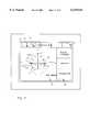
- the systemincludes an ultrasound imaging probe and associated image processing hardware and software and image display systems, a computer system which generates a user interface which accepts input from a surgeon as to the size and shape of the prostate gland imaged by the ultrasound imaging system, and calculates an optimal cryosurgical probe placement for the particular imaged prostate gland, and displays a template on the display screen indicating the optimal placement.
- the systemalso images the cryosurgical probes as they are inserted into the prostate gland, and presents the images of the cryosurgical probes on the display for comparison with the template and the optimal placement positions as calculated by the system. Using the system, the surgeon performing the procedure can be assured that the intended probe placement corresponds to optimal positions, and that the actual probe placement is accomplished according to the optimal placement.
- the algorithmsdecide whether the prostate size fits within parameters for successful calculations, whether five or sixth probes are required, the optimal placement of two cryoprobes in the anterior lobe of the prostate gland, the optimum placement for two cryoprobes in the outer portions of the posterior lobe of the prostate, and the optimum placement for one or two cryoprobes in the center area of the posterior lobe of the prostate.
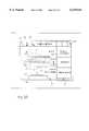
- FIG. 1is an overview of the transperineal cryosurgical ablation of the prostate.
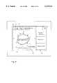
- FIG. 2is an illustration of a sagittal or longitudinal cross section of the prostate and surrounding anatomy as displayed on the video display provided by the system.
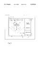
- FIG. 3is an illustration of a horizontal or transverse cross section of the prostate and surrounding anatomy as displayed on the video display provided by the system.
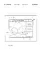
- FIG. 4is an illustration of the system in use to outline the prostate image shown in FIG. 2.
- FIG. 5is an illustration of the system in use to outline the prostate image shown in FIG. 2, illustrating measurements calculated by the computer system.
- FIG. 6is an illustration of the system in use to outline the prostate image shown in FIG. 3.
- FIG. 7is an illustration of the system in use to outline the prostate image shown in FIG. 3, illustrating measurements calculated by the computer system.
- FIG. 8is an illustration of the system determination of the optimum placement of cryoprobes within the anterior lobe of the prostate image shown in FIG. 3, where the prostate is relatively large.
- FIG. 9is an illustration of the system determination of the optimum placement of two cryoprobes within the anterior lobe of the prostate image shown in FIG. 3, where the prostate is relatively large.
- FIG. 10is an illustration of the system determination of the optimum placement of two cryoprobes within the anterior lobe of the prostate image shown in FIG. 3 where the prostate is relatively small.
- FIG. 11is an illustration of the system determination of the optimum placement of two cryoprobes within the posterior lobe of the prostate image shown in FIG. 3.
- FIG. 12is an illustration of the system determination of the optimum placement of a fifth cryoprobe within the prostate image shown in FIG. 3, in the case that only five probes are required for effective cryosurgical ablation of the prostate.
- FIG. 13is an illustration of the system determination of the optimum placement of the fifth and sixth cryoprobes within the prostate image shown in FIG. 3, in the case that a sixth probe is required for effective cryosurgical ablation of the prostate.
- FIGS. 14 through 21illustrate a second method for the system determination of the optimum placement of cryoprobes within the prostate.
- FIG. 22is an illustration of the system output indicating the optimum placement of the fifth and sixth cryoprobes within the prostate image shown in FIG. 3, in the case that a sixth probe is required for effective cryosurgical ablation of the prostate.
- FIG. 23is an illustration of the system output indicating the optimum placement of cryoprobes within the prostate image shown in FIG. 2.
- FIG. 24is an illustration of the system output indicating the optimum placement of cryoprobes within the prostate image shown in FIG. 2.
- FIG. 25is an illustration of the system output indicating the actual placement of cryoprobes in relation to the displayed optimum placement of cryoprobes within the prostate image shown in FIG. 2.
- FIG. 26is an illustration of the system output indicating the actual placement of cryoprobes in relation to the displayed optimum placement of cryoprobes within the prostate image shown in FIG. 2, displaying probes and graphical markers obscured in the view of FIG. 25.
- FIG. 27is an illustration of the system output indicating the actual placement of cryoprobes in relation to the displayed optimum placement of cryoprobes within the prostate image shown in FIG. 3.
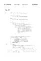
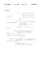
- FIG. 28is a copy of the portion of the computer program which performs the calculations used to determine the optimum placement of cryoprobes.
- FIG. 1shows one of the basic operations for which the cryoprobes are designed.
- Several probes 1, 2, 3, 4 and 5are shown inserted in the prostate 6 (in some instances a sixth probe, not shown, is used). All five probes are inserted through the perineal region 7 between the scrotum and the anus.
- Probes 2 and 3are shown inserted into the anterior lobe 6a of the prostate, and Probes 1, 4 and 5 are shown inserted into the posterior lobe 6p, which is larger than the anterior lobe.
- the probesare placed within the prostate according to procedures well known in the art, and a suitable procedure is described in step-by-step detail in Onik, et al., Percutaneous Prostate Cryoablation, (1995) at pages 108-112 and Onik, Ultrasound-Guided Cryosurgery, Scientific American at 62 (January 1996). Typically five or six probes are used in the procedure, though more or less may be used when required by unusual anatomy of a particular patient.
- the urethra 8 which passes through the prostateis one of the anatomic structures that usually should not be frozen during this surgery. Accordingly, the urethra is protected and kept warm with the urethral warming catheter 9.
- the bladder neck sphincter 10 and the external sphincter 11are also structures that should be protected from freezing, and these are protected from freezing by the warming catheter. Neurovascular bundles on the right and left of the prostate should also be protected from freezing.
- Transrectal probe 13is inserted into the rectum 14 in order to visualize the placement of the probes and the growth of the iceballs formed by the cryoprobes.
- a template 15is used which supports the probes during insertion and while they are installed in the body. The patient is placed horizontally on an operating table with legs positioned to provide access for the ultrasound probe to be inserted into the rectum and cryoprobes to be inserted through the perineal area into the prostate.
- the transrectal ultrasound probe 13is used to visualize the prostate and the cryosurgical probes.
- the ultrasound probeoperates in the range of about 2-10 MHz, depending on the equipment used (the process described herein may be used with any ultrasound probe and ultrasound generator, which may be selected based on various technical, medical and budgetary considerations).
- the imageis displayed as a two dimensional representation of the boundaries of the prostate, as illustrated in FIGS. 2 and 3.
- FIG. 2shows a longitudinal (also referred to as saggital or coronal) cross section of the prostate, generally denoted by the ultrasound outline 21.
- the top, bottom, anterior and posterior sides of the outlineare delineated by the letters T, B, A and P, respectively.
- the apex of the prostate 22points generally to the perineal area shown in FIG. 1.
- Other anatomical structures visible in displayinclude the urethra, whose outline 23 may not appear fully in the coronal cross section.
- the urethral warming catheter image 24appears within the urethra.
- the ultrasound image of the rectal wall 25appears along the bottom of the display area, and the image of the ultrasound probe 26 may appear directly below the rectal wall.
- the rectum and rectal wallare preferably straightened by the pressure exerted by the insertion of the ultrasound probe, as explained below, to set up the system for the calculations and displays described below. Since the prostate is generally oblong in this direction, and longer in this direction than in the horizontal or transverse cross section, we refer to this cross section as the longitudinal cross section.
- FIG. 3shows a horizontal or transverse cross section of the prostate generally denoted by the ultrasound outline 28.
- the anterior (towards the front of the body), posterior (toward the back), right and left of the prostateare marked as A, P, R and L, respectively.
- the urethraappears as the ultrasound outline 29.
- the warming catheter outline 24appears within the urethra image 29.
- the shadow of the probe itselfmarked as item 30, and the ultrasound outline of the rectum 31.
- the image shownis refreshed at a regular rate by the ultrasound imaging system and the images may shift with movement of the ultrasound probe.
- the surgeonis instructed to translate the ultrasound probe within the rectum to obtain several cross sectional views and to choose the largest viewable cross section of the prostate for analysis and display.
- the ultrasound display area 32is used by the system to display the image of the prostate generated by the ultrasound imaging system, and is used as described below to enter information regarding the prostate outline and display suggested probe placements.
- the toolbar area 33 across the top of the screenis used by the system to present drawing and viewing tools and other interface tools (typical selection, pen and zoom tool icons 34, 35 and 36 are illustrated in the toolbar).
- the data presentation area 37 along the right side of the screenis used by the system to indicate program information and patient information, step by step instructions to the surgeon, and measurements derived from operator inputs in the display area.
- the systemprovides a function for the operator to freeze the image in order to accept outlining and path-finding inputs followed by calculating functions.
- the operatoris prompted to orient the ultrasound image such that the rectal wall is substantially parallel to the bottom edge of the display area.
- the operatoris instructed or prompted to search for the largest cross section of the prostate as seen through the ultrasound probe, and to freeze the image on the screen.
- a single framewill be captured or grabbed by the system software and displayed as a frozen image.
- the frozen imagesare presented on the display to allow the operator to interact with the system to determine the size and shape of the prostate.
- FIG. 4shows the grabbed image of the coronal cross section of the prostate shown in FIG. 2.
- the surgeoninstructs the system to freeze the image when an appropriate cross section is displayed.
- the largest visualized cross section in which the urethra appearsshould be used.
- Visualization of the urethraindicates that the image plan is at or near the center of the prostate.
- the computer systemgrabs a frame from the live image, and presents a frozen image as illustrated in FIG. 4.
- the operatormarks at least two points 39 and 40 along the rectal wall image 25 and instructs the computer system to analyze these two points to make sure that they are sufficiently horizontal (parallel with the ultrasound probe) and straight to support later functions of the system. If the rectal wall image is not horizontal within acceptable limits (currently, not more than 4 mm difference in height on the display area), and near the bottom of the display area within acceptable limits (currently set at 3 cm), the system will reject the frozen image as a basis for later functions and prompt the operator to correct the image orientation, probe placement or patient position. If the rectal wall image is substantially horizontal on the display, indicating that the rectal wall is parallel with the ultrasound probe, the system will indicate that the image is acceptable and prompt the operator to continue the procedure and outline the prostate image on the display.
- the operatorUsing outline functions of the supporting computer system, such as the pen tool selected from the toolbar, the operator outlines the image of the prostate by moving the pen tool around the outline and anchoring the pen tool at selected points around the perimeter until the prostate is fully outlined.
- the anchor pointsmay be created by the operator with standard input devices such as a mouse or touch screen and other standard software tools such as an anchor point adding tool, pen tool or polygon tool.
- the operatorthen creates an outline of the horizontal cross section of the prostate by drawing a polygon having several anchor points 41, 42, 43, 44, 45, 46, and 47 around the perimeter of the prostate ultrasound image 21 (any number of anchor points may be used).
- the operatorindicates to the system that the outline is accurate relative to the displayed image, and the computer system accepts the image as a representation of the coronal cross section of the prostate.
- the computer systemsearches the display data for the outline and defines the two parameters H2 and L2.
- the parameter H2is the "height" of the prostate that will be considered by the system.
- the parameter L2is the length of the prostate that will be considered by the program. (It should be appreciated that any variable name may be assigned to these parameters; the H2 and L2 designations correspond to variables used in the computer program which the inventors have devised to implement the system.)
- the computer systemanalyzes the variables to assist the operator in deciding how to accomplish the cryosurgery. If L2 is greater than 35 mm, the system will notify the operator that a pullback freeze is required to completely ablate the prostate.
- the doctorwill then be apprised that a single freezing operation will be insufficient, and that the cryosurgery must be accomplished in two steps, with a first freeze being accomplished with the probe tips near the top of the prostate and the second freeze be accomplished afterward, with the cryoprobes pulled back about 10 mm toward the apex of the prostate. If H2 is less than a predetermined distance from either end of the prostate, the system will prompt the operator to verify that the outline accurately reflects the size and shape of the prostate, whereupon the process may continue or be restarted.
- FIG. 6shows the display of FIG. 3 modified by the operator with the addition of a polygon comprising several anchor points 48, 49, 50, 51, 52, 53 and 54 around the perimeter of the prostate ultrasound image 28 (any number of points may be entered).
- the operatorindicates to the system that the outline is accurate relative to the displayed image, and the computer system accepts the image as a representation of the coronal cross section of the prostate.
- the operatoris also prompted to mark the center of the urethral prostate, and enters a mark 55, which the computer system accepts as the location of the prostatic urethra in the horizontal cross section.
- the computer systemsearches the display data for the outline and defines the two parameters H1 and L1.
- the parameter H1is the "height" of the prostate that will be considered by the system, as determined in the horizontal cross section image.
- the parameter L1is the width of the prostate that will be considered by the program.
- the computer systemwill compare it with the parameter H2 (the height as determined in the coronal cross section image as shown in FIG. 5). These two parameter are expected to be the same if the operator has actually selected the largest identifiable cross section in both planes.
- H1is different from H2 by more that a predetermined amount, this indicates that the cross sections do not closely correspond to the largest actual cross section, and the computer system will prompt the operator to restart the procedure at the image selection stage (presently, 3 mm difference is the maximum allowed difference, but this may vary with experience with the present system, or with the cryoprobes in use).
- the computerUpon determining L1, the computer will compare it with a predetermined width, and if L1 is greater than the predetermined width (currently set at 3.5 cm) the system will notify the operator that six cryoprobes are required for the operation, and proceed as described below to calculate a position for the sixth cryoprobe.
- the systemwill not calculate positions for extremely large or small glands, thus if the prostate width in the anterior lobe is greater than 54 mm, the system will display a message in the instruction area that the gland is too large for calculated positioning of the probes. If the prostate width in the anterior lobe is smaller than 23 mm, the system will display a message in the instructions area that the gland is too small for calculated positioning of the probes.
- the supporting computer systemis programmed with software which permits the drawing and outlining functions described above, and calculation functions for calculating the size of the prostate based on the input, determining the optimal number of probes required, and determining the optimal placement for the probes.
- the computer systemoperates to calculate the optimum number of cryoprobes and the optimum placement of the cryoprobes, and communicate this information to the operator.
- the computer systemrequires input or calculation of certain parameters in order to determine probe placement.
- the parameters requiredare:
- prtUrethraThe location of the center of urethra within the horizontal cross section
- iY0the vertical position of the anterior extreme of the prostate gland in the horizontal cross section
- iY01 and iY5The vertical position of the rectal wall in the horizontal cross section, as approximated by the posterior extreme of the prostate gland;
- the measured parametersare used to calculate the optimum position for the placement of the cryosurgical probes.
- the optimum placement of probesis determined empirically, based upon histological evidence of lethal ablation zones, and the calculations may vary as histological data accumulates.
- the systemfirst calculates the position of probes in the horizontal plane, and from this derives the position of the probes in the coronal cross section.
- the systemuses data from the outlining step, the system first calculates the desired position of probes 2 and 3, which are placed in the interior lobe of the prostate. Referring to FIG. 8 (horizontal cross section), if L1 exceeds 3.6 cm, the computer system searches the horizontal outline of the prostate (using a line by line measurement of the display data generated by the computer system) from the top to identify the first horizontal length which equals 3.6 cm. When this line is found, as exemplified by line 57, the line is divided into four sections of equal length, and the five points P1, P2, P3, P4, and P5. The system next tests whether the distance from point P2 to the midline highest point 58 (pctrpt) is less than 9 mm.
- the systemuses this vertical position for placement of the probes 2 and 3.
- Graphical markers corresponding to Probes 2 and 3are placed on the points P2 and P4, which correspond to the middle points on the two line segments from the outer edge of the prostate to the center of the prostate at the point where the width of the prostate first measures 3.6 cm. If this distance is initially more than 9 mm, the system moves the line 57 upward until the distance is 9 mm, and adjusts P1 through P5 to match the outer edge of the prostate, the centerline of the prostate, and the points between the center and the outer edges, and uses this new vertical position for placement of probes 2 and 3. This is illustrated in FIG.
- placement of the first two probesis determined as illustrated in FIG. 10.
- the computer systemsearches the horizontal outline of the prostate (using a line by line measurement of the display data generated by the computer system) by iteratively drawing horizontal lines and identifying the five points P1 through P5, from the top to identify the first horizontal line in which the distance point P2 to the top centerline is 9 mm, or until the distance between P2 and P4 is 9 mm, whichever occurs first.
- this lineis found, as exemplified by line 61, the points P2 and P4 are identified as the position for Probes 2 and 3, respectively.
- the systemnext determines the optimal position for probes 1 and 4, which are placed in the posterior lobe of the prostate.
- the procedureis explained in reference to FIG. 11.
- the systemfinds all points at which the distance along the horizontal from the outer edge of the prostate (distance b) is one half of the distance along the vertical from the outer edge of the prostate (distance a).
- the systemnext draws the arc 65 at a distance of 18 mm from point Probe 2, and a similar arc 66 from point Probe 3.
- the point where the arc 65 and the line 63 intersectis chosen as the position of probe 1 and the point where the arc 66 and the line 64 intersect is chosen as the position of probe 4.
- these probesare positioned in this manner regardless of prostate size, except as inherited from the positioning of probes 2 and 3.
- Placement of probe 5depends on the size of the prostate. If the system has decided that 5 probes are sufficient to accomplish effective ablation, the fifth probe is placed on the line H1 between the rectal wall and the urethra. The system finds the point along H1 which is 2/3 of the way up from the rectal wall, and assigns this position to Probe 5, as illustrated in FIG. 12. If the system has decided that 6 probes are necessary (i.e., L1 is greater than 3.6 cm), the system determines the position of probes 5 and 6. As illustrated in FIG. 13, the system determines the position of these probes relative to previously placed probes.
- the systemdetermines the position of probe 6 so that it falls within 1.8 cm of probe 1, and the distance from the horizontal centerline L1 to the probe is not more than 1 cm, and the distance between from the vertical center line H1 is not more that 9 mm.
- Arc 67is drawn around Probe 1 with radius of 18 mm, and a line 68 is drawn 1 cm below L1.
- Probe 5is placed on the higher of (1) the intersection of line 69 (drawn 9 mm away from H1) with the arc 67, or (2) the intersection of the line 69 and line 68.
- a similar constructionis performed on the other side of the prostate, and probe 6 is placed within the intersection of line 70 and the arc 71 or the line 68, whichever is higher.
- Probes 5 and 6are located on the screen relative to the ultrasound image of the prostate.
- FIGS. 14 through 21illustrate a second method for the system determination of the optimum placement of cryoprobes within the prostate.
- the prostate outlineis used as before to define H1 and L1.
- the systemfinds the top of the prostate outline, and sets the variable iY0 at the top of prostate (represented by the horizontal line iY0), and sets the variable pctrpt as the x and y values at the top of the prostate.
- Minimum and maximum potential vertical levelsare defined for analysis as locations for probes 2 and 3.
- the systemdefines the variable ip2ymin at 8 mm below the line iY0 (labeled as horizontal line ip2ymin), and defines the variable ip2ymax at highest of (1) 16 mm below iY0 (labeled as horizontal line iY0+16 mm) and (2) 4 mm above the center of the urethra (labeled as horizontal line pctUrethra-4 mm), and defines the variable ip2ylimit (the lowest allowed height for probes 2 and 3) as the horizontal line 7/16 down H1 (labeled iP2ylimit).
- the systemsearches line on the screen starting at ip2ymin and continuing through to the highest of ip2ymax or ip2ylimit, which ever is higher. (If iP2ymin is lower than iP2ymax, the system sets ip2ymin as the y value for probes 2 and 3.)
- the systemsearches the region defined in FIG. 14 for the desired vertical placement of probes 2 and 3.
- the systemdetermines the length of ip2ymin, and the length of line ip2ymax across the prostate. If upper line (iP2ymin) length (dpt1topt2min) is greater than 54 mm, the outline cannot be automatically analyzed because it is too big, and the system communicates this to the operator. If the lower line (iP2ymax) length (dpt1topt2max) is smaller than 23 mm, the outline cannot be automatically analyzed because it is too small, and the system communicates this to the operator. In all other instances, the system continues on to create and define variables as follows:
- variable pt1topt2For L1 between 26 and 36 mm, create variable pt1topt2, and store the minimum value of 26 or dpt1topt2max (length of ip2ymax line) as pt1topt2;
- the systemsearches for the proper height for probes 2 and 3. From the top line (iP2ymin), the system scans each pixel line from iP2ymin to iP2ymax, searching for outside points X1 and X5 on the outline intersecting the horizontal line. When a line is found where the length of this line equals the defined dPt1toPt2 (calculated in reference to FIG. 15, above), that line is used as the vertical placement of probes 2 and 3. The corresponding line in FIG. 16 is labeled 72. Finally, the system calculates the x values for probes 2 and 3, setting them along the line at a spacing of 1/4 and 3/4 from the left, respectively.
- the systemdetermines the position of two probes in the anterior lobe of the prostate based upon the width of the prostate approximately at the anterior-most location of (1) 16 mm posterior to the anterior extremity of the prostate, (2) 4 mm anterior to the center of the prostatic urethra, or (3) 7/16 of the total thickness of the prostate from the anterior extremity of the prostate.
- the systemanalyzes the outline to determine the proper location of probes 1 and 4 in the posterior lobe of the prostate.
- the systemdefines the vertical location iY01 (horizontal line iY01 in FIG. 17) as the y value or line at 5/8 down the prostate (5/8 down the length of H1).
- the systemdetermines the Y distance between iY01 line and probes 2 and 3 (about 10 mm, as illustrated). If this distance is less than 16 mm, the system uses iY01 line as vertical height for placement of probes 1 and 4. Here, iY01 is only 10 mm away, so this is height for probes 1 and 4. If the distance is greater than 16 mm, the system raises line iY01 until it is only 16 mm down from probes 2 and 3.
- the systemplaces point iXL 1/6 across iY01 line, and if greater than 18 mm from probe 2, slide right (or left) until the point is 18 mm from probe 2 (i.e., within circle 73, drawn at a radius of 18 mm from probe 2).
- the systemplaces point iXR 5/6 of the distance across the line iY01, and if greater than 18 mm from probe 3, the point is moved left (or right) until the point is 18 mm from probe 3 (i.e., within circle 74, drawn at a radius of 18 mm from probe 3).
- FIG. 18illustrates the same procedure in relation to a larger prostate which requires sliding point iXR to the left after initial placement at 5/6 across line iY01, so that it comes within 18 mm of probe 3 (and meets circle 74). In all other respects, FIG. 18 is described in the same manner as FIG. 17.
- the systemdetermines the position of two probes in the posterior lobe of the prostate based upon the width of the prostate at the anterior-most location of (1) approximately 5/8 of the total thickness of the prostate from the anterior extremity of the prostate or (2) 16 mm posterior to the two probes positioned in the anterior lobe of the prostate.
- the systemdetermines the placement of Probes 5 and 6 within the posterior lobe of the prostate.
- the systemsets line iY01 as y height of probes 1 and 4, and sets the horizontal line iY56 at 1/4 up from bottom of screen (prostate/rectum/screen bottom are in reality so close together that they may be treated as the same y level), and sets the line (labeled as the horizontal line iY01+16) 16 mm down from probes 1 and 4.
- the systemresets line iY56 at the highest (the minimum y value) of the two lines, here the 1/4 up line is chosen.
- the systemplaces points X5 and X6 at left and right extremities of line iY56, which is the intersection of the prostate outline with iY56.
- FIG. 20illustrates the placement of probes 5 and 6 in a larger prostate, to illustrate the system choice of the highest line for placement of the probes.
- line iY56is below line iY01+16, so line iY56 is reset to the height of line iY01+16.
- the points X5 and X6are moved inward along the higher line until they are only 10 mm apart, and probes 5 and 6 are located at these points, as illustrated in the figure.
- the systemdetermines the position of the two probes 5 and 6 in the center portion of the posterior lobe of the prostate based upon the width of the prostate at a the anterior-most location of (1) approximately 1/4 of the distance on the display from the rectum to the top of the display; (2) 16 mm posterior to the two probes 1 and 4 already positioned in the posterior lobe of the prostate.
- probe 5In a prostate where L1 is less that 35 mm across, only probe 5 is used, and it is located at or near the horizontal center of the prostate outline. As illustrated in FIG. 21, the system sets iY5 at bottom of outline. The system also defines the horizontal line 1/3 the way down H1 from the urethra to rectum (the horizontal line labeled as pctUrethra+1/3), and defines the horizontal line 18 mm above iY5 (the horizontal line labeled iY5-18). The system then selects the lowest of these two lines as the vertical position for probe 5. Probe 5 is placed horizontally on the horizontal midpoint between probes 1 and 4 (expected to be on or near H1).
- the systemplaces probe 5, based upon the width of the prostate, in the center portion of the prostate at the posterior-most location of (1) 1/3 the distance posterior from the urethra to the rectum or (2) 18 mm anterior to the posterior extremity of the prostate
- the systemgraphically displays the desired locations to assist the operator in placing the actual probes in the prostate of the patient.
- the optimal location of the probesis indicated in the horizontal cross section by a graphic representation overlaid over the live ultrasound images of FIGS. 3 and 2 and/or the still images of FIGS. 6 and 4.
- the desired representationis illustrated in FIGS. 22 and 25.
- FIG. 22is an illustration of the system output indicating the optimum placement of cryoprobes within the prostate horizontal cross sectional image shown in FIG. 2.
- the suggested probe placementis indicated by graphical markers 75, 76, 77, 78, 79 and 80 for Probes 1, 2, 3 4, 5 and 6 respectively. The markers are placed in the display by the computer system, overlaying the ultrasound image of the prostate horizontal cross section.
- FIGS. 23 and 24show the display presented by the computer system of graphical markers for each probe. The vertical position of the probes is dependent on the positions calculated in reference to calculated positions in the horizontal cross section.
- FIGS. 23 and 24show the system output indicating the optimum placement of cryoprobes within the prostate longitudinal cross sectional image shown in FIG. 3.
- the suggested probe placement, as viewed on the saggital plane,is indicated by graphical markers, 81, 82, 83, 84, 85 and 86.
- the markersare placed in the display by the computer system, overlaying the ultrasound image of the prostate saggital cross section.
- probes 2 and 3, and probes 1 and 4, and probes 5 and 6are likely to be symmetrically located in reference to the line H1, the probes in these pairs will overlap in this view.
- probes 3, 4 and 6are displayed as shown in FIG. 24.
- the computer systempermits the operator to switch between views of FIG. 23 and FIG. 24.
- FIG. 23is used by the operator to assist in placement of Probes 1, 2 and 5, while FIG. 24 is used to assist in placement of Probes 3, 4 and 6.
- FIGS. 25, 26 and 27illustrate the feedback provided to the operator indicating the actual position of the cryoprobes in relation to the suggested placement shown in FIGS. 22, 23 and 24.
- the graphical markers 75, 76, 77, 78, and 80are shown in the horizontal cross section, displayed as generated by the computer system.
- the ultrasound image of the probesis displayed in the display area, since the probes enter the ultrasound imaging field and are imaged by the ultrasound imaging system.
- Probe 1has been placed in good correspondence with the template provided by the computer, and the ultrasound image is aligned with the graphical marker 75.
- Probe 2has been placed in a position different than its associated graphical marker 76, and the surgeon may decide on that basis to reinsert the probe to more closely align it with the marker.
- Probe 3has been placed close to the marker 77, and the surgeon may decide to reposition the probe or to leave it in place.
- Probes 4 and 5appear in the display on or near their associated markers 78 and 80, providing feedback to the surgeon ensuring proper placement of the probes.
- FIG. 25shows the graphical markers 81, 82 and 85, displayed as generated by the computer system.
- the ultrasound image of the probesis displayed in the display area, since the probes enter the ultrasound imaging field and are imaged by the ultrasound imaging system. Again, the surgeon may view the ultrasound image of the actual probes, and place the probes as closely as possible positions corresponding to the markers.
- FIG. 26shows a display containing the graphical markers 83 and 84 corresponding to probes 3 and 4 which are located on the right side of the prostate relative to the anterior/posterior centerline. These displays help the operator in placing the probes as desired in parallel relationship with the ultrasound probe and the rectal wall. The operator may switch repeatedly being the displays of FIGS.
- cryoprobe placementis satisfactory, the surgeon will start the flow of cooling gas to freeze the prostate.
- the freezing operationcan be confirmed in the ultrasound image by watching the iceballs (the mass of frozen tissue) around each cryoprobe form.
- the extent of the iceballs and the extent of the prostate that is frozenis monitored to ensure that substantially all of the prostate is frozen.
- the freezing processmay be repeated to ensure ablation of the prostate.
- the section of the computer program which performs these calculationsis provided as FIG. 28, which is programmed in the C++ programming language.
- the programimplements the second method described above in relation to FIGS. 14 through 22.
- the section of the code which finds the proper vertical location for probes 2 and 3 in the anterior lobe of the prostatestarts at item number 90.
- the section of code which determines if the gland is too large or smallis indicated by item number 91.
- the section of the code which finds the proper horizontal and vertical location for probes 2 and 3 in the anterior lobe of the prostateis labeled as item 92.
- the section of the program which calculates the position of probes 1 and 4is indicated by item number 93.
- This segment of codealso incorporates a test for adequate symmetry of the prostate, in that if probe 1 or probe 4 cannot be properly place, the system communicates this to the operator (leading to re-imaging or cancellation of the computer assisted surgery).
- the section of the program which calculates the position of probes 5 and 6 (or only probe 5)is indicated by item number 94.
- cryosurgery of the prostateby calculating optimal positions for cryoprobes and providing display based templates for overlay over an ultrasound image display, and displaying actual cryoprobe ultrasound images together with template images so that the surgeon may compare suggested and actual placement of the probes, and adjust placement accordingly.
- the method and systemis described above in relation to our CRYOcareTM cryosurgical system, which is provided with up to eight independently controlled 3 mm argon powered cryoprobes.
- the systemcools the probes to cryosurgically effective temperatures (typically below -120° C.) through Joule-Thomson cooling within the probe tips.
- the systemmay be implemented with other cooling systems such as liquid nitrogen cryoprobes and mixed gas cryoprobes.
- probesThe placement of probes is calculated based on this system, and the calculations may be adjusted for different systems and numbers of probes.
- the systemhas been described with ultrasound as the imaging mechanism and the rectum as the point of view, the system may be implemented with other imaging systems such as fluoroscopy or new imaging systems.
- the systemmay be adapted to other forms of ablation and treatment of the prostate or other organs, with adjustments in the calculations being made to account for the ablative range of the devices used and the geometry of the organ.
- the preferred embodiments of the devices and methodshave been described in reference to the environment in which they were developed, they are merely illustrative of the principles of the inventions. Other embodiments and configurations may be devised without departing from the spirit of the inventions and the scope of the appended claims.
Landscapes
- Health & Medical Sciences (AREA)
- Surgery (AREA)
- Life Sciences & Earth Sciences (AREA)
- Nuclear Medicine, Radiotherapy & Molecular Imaging (AREA)
- Biomedical Technology (AREA)
- Engineering & Computer Science (AREA)
- Otolaryngology (AREA)
- Heart & Thoracic Surgery (AREA)
- Medical Informatics (AREA)
- Molecular Biology (AREA)
- Animal Behavior & Ethology (AREA)
- General Health & Medical Sciences (AREA)
- Public Health (AREA)
- Veterinary Medicine (AREA)
- Ultra Sonic Daignosis Equipment (AREA)
Abstract
Description
Claims (2)
Priority Applications (11)
| Application Number | Priority Date | Filing Date | Title |
|---|---|---|---|
| US09/318,710US6139544A (en) | 1999-05-26 | 1999-05-26 | Computer guided cryosurgery |
| EP00930837AEP1158922A4 (en) | 1999-05-26 | 2000-05-22 | Computer guided cryosurgery |
| PCT/US2000/014056WO2000072773A1 (en) | 1999-05-26 | 2000-05-22 | Computer guided cryosurgery |
| AU48591/00AAU4859100A (en) | 1999-05-26 | 2000-05-22 | Computer guided cryosurgery |
| US09/699,938US6485422B1 (en) | 1999-05-26 | 2000-10-30 | Computer guided cryosurgery |
| US09/957,306US6544176B2 (en) | 1999-05-26 | 2001-09-20 | Computer guided cryosurgery |
| US09/981,336US6694170B1 (en) | 1999-05-26 | 2001-10-16 | Computer guided surgery for prostatic nerve sparing |
| US10/120,722US20020198518A1 (en) | 1999-05-26 | 2002-04-11 | Entry position grid for computer guided cryosurgery |
| US10/307,036US6643535B2 (en) | 1999-05-26 | 2002-11-27 | System for providing computer guided ablation of tissue |
| US10/700,326US7363071B2 (en) | 1999-05-26 | 2003-03-11 | Computer guided ablation of tissue using integrated ablative/temperature sensing devices |
| US12/025,619US9326808B2 (en) | 1999-05-26 | 2008-02-04 | System for providing computer guided ablation of tissue |
Applications Claiming Priority (1)
| Application Number | Priority Date | Filing Date | Title |
|---|---|---|---|
| US09/318,710US6139544A (en) | 1999-05-26 | 1999-05-26 | Computer guided cryosurgery |
Related Child Applications (1)
| Application Number | Title | Priority Date | Filing Date |
|---|---|---|---|
| US09/699,938ContinuationUS6485422B1 (en) | 1999-05-26 | 2000-10-30 | Computer guided cryosurgery |
Publications (1)
| Publication Number | Publication Date |
|---|---|
| US6139544Atrue US6139544A (en) | 2000-10-31 |
Family
ID=23239299
Family Applications (3)
| Application Number | Title | Priority Date | Filing Date |
|---|---|---|---|
| US09/318,710Expired - LifetimeUS6139544A (en) | 1999-05-26 | 1999-05-26 | Computer guided cryosurgery |
| US09/699,938Expired - LifetimeUS6485422B1 (en) | 1999-05-26 | 2000-10-30 | Computer guided cryosurgery |
| US09/957,306Expired - LifetimeUS6544176B2 (en) | 1999-05-26 | 2001-09-20 | Computer guided cryosurgery |
Family Applications After (2)
| Application Number | Title | Priority Date | Filing Date |
|---|---|---|---|
| US09/699,938Expired - LifetimeUS6485422B1 (en) | 1999-05-26 | 2000-10-30 | Computer guided cryosurgery |
| US09/957,306Expired - LifetimeUS6544176B2 (en) | 1999-05-26 | 2001-09-20 | Computer guided cryosurgery |
Country Status (4)
| Country | Link |
|---|---|
| US (3) | US6139544A (en) |
| EP (1) | EP1158922A4 (en) |
| AU (1) | AU4859100A (en) |
| WO (1) | WO2000072773A1 (en) |
Cited By (117)
| Publication number | Priority date | Publication date | Assignee | Title |
|---|---|---|---|---|
| US6311084B1 (en)* | 1998-05-04 | 2001-10-30 | Robert A. Cormack | Radiation seed implant method and apparatus |
| US20020068928A1 (en)* | 2000-11-10 | 2002-06-06 | Werneth Randell L. | Apparatus and method to diagnose and treat vulnerable plaque |
| US6485422B1 (en)* | 1999-05-26 | 2002-11-26 | Endocare, Inc. | Computer guided cryosurgery |
| US20020198518A1 (en)* | 1999-05-26 | 2002-12-26 | Mikus Paul W. | Entry position grid for computer guided cryosurgery |
| US20030083574A1 (en)* | 2001-05-16 | 2003-05-01 | Svaasand Lars Othar | Cryosurgical apparatus and methods |
| US6612990B1 (en)* | 1999-04-08 | 2003-09-02 | Rick L. Pruter | Method and apparatus for guiding needles |
| US6643535B2 (en) | 1999-05-26 | 2003-11-04 | Endocare, Inc. | System for providing computer guided ablation of tissue |
| US20030220634A1 (en)* | 2000-08-09 | 2003-11-27 | Ryba Eric L. | Refrigeration source for a cryoablation catheter |
| US6692487B2 (en)* | 2002-01-23 | 2004-02-17 | Endocare, Inc. | Cryosurgical monitoring system |
| US6694170B1 (en) | 1999-05-26 | 2004-02-17 | Endocare, Inc. | Computer guided surgery for prostatic nerve sparing |
| US20040034345A1 (en)* | 2002-08-16 | 2004-02-19 | Lentz David J. | Heat transfer segment for a cryoablation catheter |
| US20040034344A1 (en)* | 2002-08-16 | 2004-02-19 | Eric Ryba | Tip pressure monitoring for cryoablation catheters |
| US20040049177A1 (en)* | 2000-10-24 | 2004-03-11 | Roni Zvuloni | Multiple cryoprobe apparatus and method |
| US6758817B1 (en) | 2002-09-11 | 2004-07-06 | Protek Medical Products, Inc. | Method and disposable apparatus for guiding needles |
| US20040143181A1 (en)* | 1999-05-26 | 2004-07-22 | Damasco Sanford D. | Computer guided ablation of tissue using integrated ablative/temperature sensing devices |
| US20040215294A1 (en)* | 2003-01-15 | 2004-10-28 | Mediphysics Llp | Cryotherapy probe |
| US20040243118A1 (en)* | 2001-06-01 | 2004-12-02 | Ayers Gregory M. | Device and method for positioning a catheter tip for creating a cryogenic lesion |
| US20040243117A1 (en)* | 2002-12-11 | 2004-12-02 | Lentz David J. | Catheter system for performing a single step cryoablation |
| US20050016188A1 (en)* | 2003-07-24 | 2005-01-27 | Lentz David J. | Distal end for cryoablation catheters |
| US20050027289A1 (en)* | 2003-07-31 | 2005-02-03 | Thomas Castellano | Cryoablation systems and methods |
| US6884219B1 (en) | 2002-10-17 | 2005-04-26 | Rick L. Pruter | Method and disposable apparatus for guiding needles with an endocavity medical imaging device |
| US20050177146A1 (en)* | 2004-02-10 | 2005-08-11 | Marshall Sherman | System and method for assessing ice ball formation during a cryoablation procedure |
| US20050198972A1 (en)* | 2004-03-10 | 2005-09-15 | Lentz David J. | Pressure-temperature control for a cryoablation catheter system |
| US20050224085A1 (en)* | 2000-10-24 | 2005-10-13 | Roni Zvuloni | Apparatus and method for compressing a gas, and cryosurgery system and method utilizing same |
| US20050251124A1 (en)* | 2001-05-21 | 2005-11-10 | Galil Medical Ltd. | Apparatus and method for cryosurgery within a body cavity |
| US20050261753A1 (en)* | 2003-01-15 | 2005-11-24 | Mediphysics Llp | Methods and systems for cryogenic cooling |
| US20050283146A1 (en)* | 2004-06-17 | 2005-12-22 | Lentz David J | Thermally extended spiral cryotip for a cryoablation catheter |
| US20050288658A1 (en)* | 2002-10-04 | 2005-12-29 | Sanarus Medical, Inc. | Method and system for cryoablating tumors |
| US20050288657A1 (en)* | 2004-06-29 | 2005-12-29 | Lentz David J | Pressure monitor for cryoablation catheter |
| US20060004350A1 (en)* | 2004-06-30 | 2006-01-05 | Eric Ryba | System and method for varying return pressure to control tip temperature of a cryoablation catheter |
| US20060004349A1 (en)* | 2004-06-30 | 2006-01-05 | Eric Ryba | System for detecting leaks and occlusions in a cryoablation catheter |
| US20060025761A1 (en)* | 2004-07-29 | 2006-02-02 | Riley Lee B | Linear-array radio frequency resections |
| US20060069385A1 (en)* | 2004-09-28 | 2006-03-30 | Scimed Life Systems, Inc. | Methods and apparatus for tissue cryotherapy |
| US20060079867A1 (en)* | 2003-04-03 | 2006-04-13 | Nir Berzak | Apparatus and method for accurately delimited cryoablation |
| US7083612B2 (en) | 2003-01-15 | 2006-08-01 | Cryodynamics, Llc | Cryotherapy system |
| US20070088247A1 (en)* | 2000-10-24 | 2007-04-19 | Galil Medical Ltd. | Apparatus and method for thermal ablation of uterine fibroids |
| US20070156125A1 (en)* | 2005-12-30 | 2007-07-05 | Russell Delonzor | Encodable cryogenic device |
| US20070255117A1 (en)* | 2001-01-30 | 2007-11-01 | Barnes-Jewish Hospital | Enhanced ultrasound detection with temperature-dependent contrast agents |
| US20080027420A1 (en)* | 2006-07-25 | 2008-01-31 | Ams Research Corporation | Cryosurgical Imaging and Monitoring Systems |
| US20080045934A1 (en)* | 2000-10-24 | 2008-02-21 | Galil Medical Ltd. | Device and method for coordinated insertion of a plurality of cryoprobes |
| US20080051657A1 (en)* | 2005-02-28 | 2008-02-28 | Rold Michael D | Systems And Methods For Estimating The Size And Position Of A Medical Device To Be Applied Within A Patient |
| US20080051774A1 (en)* | 2001-05-21 | 2008-02-28 | Galil Medical Ltd. | Device and method for coordinated insertion of a plurality of cryoprobes |
| US20080051776A1 (en)* | 2001-05-21 | 2008-02-28 | Galil Medical Ltd. | Thin uninsulated cryoprobe and insulating probe introducer |
| US20080161687A1 (en)* | 2006-12-29 | 2008-07-03 | Suri Jasjit S | Repeat biopsy system |
| US20080228166A1 (en)* | 2004-05-17 | 2008-09-18 | Gergely Robert Z | Sonography guided embryo transfer for in vitro fertilization |
| WO2008090484A3 (en)* | 2007-01-24 | 2008-10-23 | Koninkl Philips Electronics Nv | Rf ablation planner |
| US7452331B1 (en) | 1999-04-08 | 2008-11-18 | Rick L Pruter | Vascular adjustable multi-gauge tilt-out method and apparatus for guiding needles |
| US20090292279A1 (en)* | 2006-01-26 | 2009-11-26 | Galil Medical Ltd. | Device and Method for Coordinated Insertion of a Plurality of Cryoprobes |
| US20110015628A1 (en)* | 2007-01-24 | 2011-01-20 | Koninklijke Philips Electronics N.V. | Advanced ablation planning |
| EP2311398A1 (en) | 2003-01-15 | 2011-04-20 | Cryodynamics, LLC. | Cryotherapy probe and system |
| US20110105823A1 (en)* | 2009-10-30 | 2011-05-05 | Angiodynamics, Inc. | Medical Template Device and Method for Use in Positioning Therapeutic Probes at a Target Tissue |
| US8007847B2 (en) | 2004-01-13 | 2011-08-30 | Eytan Biderman | Feeding formula appliance |
| US20110238051A1 (en)* | 2010-01-25 | 2011-09-29 | Zeltiq Aesthetics, Inc. | Home-use applicators for non-invasively removing heat from subcutaneous lipid-rich cells via phase change coolants, and associated devices, systems and methods |
| US8187260B1 (en)* | 2006-12-29 | 2012-05-29 | Endocare, Inc. | Variable cryosurgical probe planning system |
| US8353840B1 (en) | 2002-09-11 | 2013-01-15 | Pruter Rick L | Method and disposable apparatus for guiding needles with a double button unlocking and locking mechanism |
| US20130060242A1 (en)* | 2008-12-23 | 2013-03-07 | Cryomedix Llc | Isotherm-based tissue ablation control method |
| US8401620B2 (en) | 2006-10-16 | 2013-03-19 | Perfint Healthcare Private Limited | Needle positioning apparatus and method |
| US8613748B2 (en) | 2010-11-10 | 2013-12-24 | Perfint Healthcare Private Limited | Apparatus and method for stabilizing a needle |
| JP2014239767A (en)* | 2013-06-11 | 2014-12-25 | ジーイー・メディカル・システムズ・グローバル・テクノロジー・カンパニー・エルエルシー | Insertion target point setting apparatus, and ultrasound diagnostic apparatus |
| US20150051861A1 (en)* | 2012-03-29 | 2015-02-19 | Koninklijke Philips N.V. | Quality assurance system and method for navigation-assisted procedures |
| US8986188B2 (en) | 2007-04-28 | 2015-03-24 | The Board Of Trustees Of The Leland Stanford Junior University | Dynamic and adjustable support devices |
| US9113989B2 (en) | 2007-08-14 | 2015-08-25 | The Board Of Trustees Of The Leland Stanford Junior University | Methods and devices for supporting, elevating, or compressing internal structures |
| US9375345B2 (en) | 2006-09-26 | 2016-06-28 | Zeltiq Aesthetics, Inc. | Cooling device having a plurality of controllable cooling elements to provide a predetermined cooling profile |
| US9408745B2 (en) | 2007-08-21 | 2016-08-09 | Zeltiq Aesthetics, Inc. | Monitoring the cooling of subcutaneous lipid-rich cells, such as the cooling of adipose tissue |
| US20160235481A1 (en)* | 2015-02-13 | 2016-08-18 | Scapa Flow, Llc | System and method for medical device placement in bone |
| US9545523B2 (en) | 2013-03-14 | 2017-01-17 | Zeltiq Aesthetics, Inc. | Multi-modality treatment systems, methods and apparatus for altering subcutaneous lipid-rich tissue |
| USD777338S1 (en) | 2014-03-20 | 2017-01-24 | Zeltiq Aesthetics, Inc. | Cryotherapy applicator for cooling tissue |
| US9655770B2 (en) | 2007-07-13 | 2017-05-23 | Zeltiq Aesthetics, Inc. | System for treating lipid-rich regions |
| US9737434B2 (en) | 2008-12-17 | 2017-08-22 | Zeltiq Aestehtics, Inc. | Systems and methods with interrupt/resume capabilities for treating subcutaneous lipid-rich cells |
| US9844460B2 (en) | 2013-03-14 | 2017-12-19 | Zeltiq Aesthetics, Inc. | Treatment systems with fluid mixing systems and fluid-cooled applicators and methods of using the same |
| US9861421B2 (en) | 2014-01-31 | 2018-01-09 | Zeltiq Aesthetics, Inc. | Compositions, treatment systems and methods for improved cooling of lipid-rich tissue |
| US9861520B2 (en) | 2009-04-30 | 2018-01-09 | Zeltiq Aesthetics, Inc. | Device, system and method of removing heat from subcutaneous lipid-rich cells |
| US10092346B2 (en) | 2010-07-20 | 2018-10-09 | Zeltiq Aesthetics, Inc. | Combined modality treatment systems, methods and apparatus for body contouring applications |
| US10383787B2 (en) | 2007-05-18 | 2019-08-20 | Zeltiq Aesthetics, Inc. | Treatment apparatus for removing heat from subcutaneous lipid-rich cells and massaging tissue |
| US10524956B2 (en) | 2016-01-07 | 2020-01-07 | Zeltiq Aesthetics, Inc. | Temperature-dependent adhesion between applicator and skin during cooling of tissue |
| US10543032B2 (en) | 2014-11-13 | 2020-01-28 | Adagio Medical, Inc. | Pressure modulated cryoablation system and related methods |
| US10555831B2 (en) | 2016-05-10 | 2020-02-11 | Zeltiq Aesthetics, Inc. | Hydrogel substances and methods of cryotherapy |
| US10568759B2 (en) | 2014-08-19 | 2020-02-25 | Zeltiq Aesthetics, Inc. | Treatment systems, small volume applicators, and methods for treating submental tissue |
| US10610280B1 (en) | 2019-02-02 | 2020-04-07 | Ayad K. M. Agha | Surgical method and apparatus for destruction and removal of intraperitoneal, visceral, and subcutaneous fat |
| US10617459B2 (en) | 2014-04-17 | 2020-04-14 | Adagio Medical, Inc. | Endovascular near critical fluid based cryoablation catheter having plurality of preformed treatment shapes |
| US10667854B2 (en) | 2013-09-24 | 2020-06-02 | Adagio Medical, Inc. | Endovascular near critical fluid based cryoablation catheter and related methods |
| US10675176B1 (en) | 2014-03-19 | 2020-06-09 | Zeltiq Aesthetics, Inc. | Treatment systems, devices, and methods for cooling targeted tissue |
| US10682297B2 (en) | 2016-05-10 | 2020-06-16 | Zeltiq Aesthetics, Inc. | Liposomes, emulsions, and methods for cryotherapy |
| US10765552B2 (en) | 2016-02-18 | 2020-09-08 | Zeltiq Aesthetics, Inc. | Cooling cup applicators with contoured heads and liner assemblies |
| WO2020226693A1 (en)* | 2019-05-03 | 2020-11-12 | Neil Glossop | Systems, methods, and devices for registering and tracking organs during interventional procedures |
| US10864031B2 (en) | 2015-11-30 | 2020-12-15 | Adagio Medical, Inc. | Ablation method for creating elongate continuous lesions enclosing multiple vessel entries |
| US10935174B2 (en) | 2014-08-19 | 2021-03-02 | Zeltiq Aesthetics, Inc. | Stress relief couplings for cryotherapy apparatuses |
| US10952891B1 (en) | 2014-05-13 | 2021-03-23 | Zeltiq Aesthetics, Inc. | Treatment systems with adjustable gap applicators and methods for cooling tissue |
| US11013547B2 (en) | 2017-06-30 | 2021-05-25 | R2 Technologies, Inc. | Dermatological cryospray devices having linear array of nozzles and methods of use |
| US11051867B2 (en) | 2015-09-18 | 2021-07-06 | Adagio Medical, Inc. | Tissue contact verification system |
| US11076879B2 (en) | 2017-04-26 | 2021-08-03 | Zeltiq Aesthetics, Inc. | Shallow surface cryotherapy applicators and related technology |
| US11154418B2 (en) | 2015-10-19 | 2021-10-26 | Zeltiq Aesthetics, Inc. | Vascular treatment systems, cooling devices, and methods for cooling vascular structures |
| US20220176155A1 (en)* | 2019-04-01 | 2022-06-09 | Koninklijke Philips N.V. | Treatment planning for focal therapy treatments |
| US11382790B2 (en) | 2016-05-10 | 2022-07-12 | Zeltiq Aesthetics, Inc. | Skin freezing systems for treating acne and skin conditions |
| US11395760B2 (en) | 2006-09-26 | 2022-07-26 | Zeltiq Aesthetics, Inc. | Tissue treatment methods |
| US11446175B2 (en) | 2018-07-31 | 2022-09-20 | Zeltiq Aesthetics, Inc. | Methods, devices, and systems for improving skin characteristics |
| US11564725B2 (en) | 2017-09-05 | 2023-01-31 | Adagio Medical, Inc. | Ablation catheter having a shape memory stylet |
| US11707629B2 (en) | 2009-05-28 | 2023-07-25 | Angiodynamics, Inc. | System and method for synchronizing energy delivery to the cardiac rhythm |
| US11723710B2 (en) | 2016-11-17 | 2023-08-15 | Angiodynamics, Inc. | Techniques for irreversible electroporation using a single-pole tine-style internal device communicating with an external surface electrode |
| US11751930B2 (en) | 2018-01-10 | 2023-09-12 | Adagio Medical, Inc. | Cryoablation element with conductive liner |
| US11779395B2 (en) | 2011-09-28 | 2023-10-10 | Angiodynamics, Inc. | Multiple treatment zone ablation probe |
| US11832886B2 (en) | 2017-08-14 | 2023-12-05 | Circinus Medical Technology Llc | System and method using augmented reality with shape alignment for medical device placement |
| US11857240B2 (en) | 2019-01-14 | 2024-01-02 | Cryoelectric Science Ltd. | Methods, systems, and apparatuses for cryosurgery, coldsurgery, and electrolysis |
| US11931096B2 (en) | 2010-10-13 | 2024-03-19 | Angiodynamics, Inc. | System and method for electrically ablating tissue of a patient |
| US11957405B2 (en) | 2013-06-13 | 2024-04-16 | Angiodynamics, Inc. | Methods of sterilization and treating infection using irreversible electroporation |
| US11974816B2 (en) | 2018-12-21 | 2024-05-07 | R2 Technologies, Inc. | Automated control and positioning systems for dermatological cryospray devices |
| US11986421B2 (en) | 2006-09-26 | 2024-05-21 | Zeltiq Aesthetics, Inc. | Cooling devices with flexible sensors |
| US12063433B2 (en) | 2019-04-15 | 2024-08-13 | Circinus Medical Technology Llc | Orientation calibration system for image capture |
| US12064186B2 (en) | 2021-02-02 | 2024-08-20 | Circinus Medical Technology Llc | Systems and methods for simulating three-dimensional orientations of surgical hardware devices about an insertion point of an anatomy |
| US12070411B2 (en) | 2006-04-28 | 2024-08-27 | Zeltiq Aesthetics, Inc. | Cryoprotectant for use with a treatment device for improved cooling of subcutaneous lipid-rich cells |
| US12102376B2 (en) | 2012-02-08 | 2024-10-01 | Angiodynamics, Inc. | System and method for increasing a target zone for electrical ablation |
| US12114911B2 (en) | 2014-08-28 | 2024-10-15 | Angiodynamics, Inc. | System and method for ablating a tissue site by electroporation with real-time pulse monitoring |
| US12133669B2 (en) | 2018-12-21 | 2024-11-05 | R2 Technologies, Inc. | Automated dermatological cryospray treatment planning system |
| US12201349B2 (en) | 2009-04-03 | 2025-01-21 | Angiodynamics, Inc. | Congestive obstruction pulmonary disease (COPD) |
| US12400355B2 (en) | 2020-11-19 | 2025-08-26 | Circinus Medical Technology Llc | Systems and methods for artificial intelligence based image analysis for placement of surgical appliance |
| US12433690B2 (en) | 2021-04-14 | 2025-10-07 | Circinus Medical Technology Llc | System and method for lidar-based anatomical mapping |
| US12440279B2 (en) | 2020-04-15 | 2025-10-14 | Circinus Medical Technology, LLC | Attachment apparatus to secure a medical alignment device to align a tool |
Families Citing this family (93)
| Publication number | Priority date | Publication date | Assignee | Title |
|---|---|---|---|---|
| US7547307B2 (en)* | 2001-02-27 | 2009-06-16 | Smith & Nephew, Inc. | Computer assisted knee arthroplasty instrumentation, systems, and processes |
| US20050113846A1 (en)* | 2001-02-27 | 2005-05-26 | Carson Christopher P. | Surgical navigation systems and processes for unicompartmental knee arthroplasty |
| DE60232315D1 (en)* | 2001-02-27 | 2009-06-25 | Smith & Nephew Inc | SURGICAL NAVIGATION SYSTEM FOR PARTIAL KNEE JOINT CONSTRUCTION |
| JP2005516724A (en) | 2002-02-11 | 2005-06-09 | スミス アンド ネフュー インコーポレーテッド | Image guided fracture reduction |
| CA2507289C (en)* | 2002-11-27 | 2011-08-09 | Endocare, Inc. | System for providing computer guided ablation of tissue |
| US9655676B2 (en)* | 2003-05-16 | 2017-05-23 | Trod Medical | Method of percutaneous localized or focal treatment of prostate lesions using radio frequency |
| US7862570B2 (en) | 2003-10-03 | 2011-01-04 | Smith & Nephew, Inc. | Surgical positioners |
| US7764985B2 (en)* | 2003-10-20 | 2010-07-27 | Smith & Nephew, Inc. | Surgical navigation system component fault interfaces and related processes |
| US20050085822A1 (en)* | 2003-10-20 | 2005-04-21 | Thornberry Robert C. | Surgical navigation system component fault interfaces and related processes |
| ATE495706T1 (en) | 2003-11-14 | 2011-02-15 | Smith & Nephew Inc | ADJUSTABLE SURGICAL CUTTING SYSTEMS |
| WO2005053559A1 (en)* | 2003-11-25 | 2005-06-16 | Smith & Nephew, Inc. | Methods and apparatuses for providing a navigational array |
| US20050113659A1 (en)* | 2003-11-26 | 2005-05-26 | Albert Pothier | Device for data input for surgical navigation system |
| WO2005072629A1 (en)* | 2004-01-16 | 2005-08-11 | Smith & Nephew, Inc. | Computer-assisted ligament balancing in total knee arthroplasty |
| US20050159759A1 (en)* | 2004-01-20 | 2005-07-21 | Mark Harbaugh | Systems and methods for performing minimally invasive incisions |
| WO2005070319A1 (en)* | 2004-01-22 | 2005-08-04 | Smith & Nephew, Inc. | Methods, systems, and apparatuses for providing patient-mounted surgical navigational sensors |
| CA2561493A1 (en)* | 2004-03-31 | 2005-10-20 | Smith & Nephew, Inc. | Methods and apparatuses for providing a reference array input device |
| US20050234466A1 (en)* | 2004-03-31 | 2005-10-20 | Jody Stallings | TLS adjustable block |
| US20050234465A1 (en)* | 2004-03-31 | 2005-10-20 | Mccombs Daniel L | Guided saw with pins |
| JP4808704B2 (en)* | 2004-04-15 | 2011-11-02 | スミス アンド ネフュー インコーポレーテッド | Detachable and repositionable reference frame for computer-assisted surgery |
| EP1737375B1 (en)* | 2004-04-21 | 2021-08-11 | Smith & Nephew, Inc | Computer-aided navigation systems for shoulder arthroplasty |
| US20050279368A1 (en)* | 2004-06-16 | 2005-12-22 | Mccombs Daniel L | Computer assisted surgery input/output systems and processes |
| JP2008521574A (en)* | 2004-12-02 | 2008-06-26 | スミス アンド ネフュー インコーポレーテッド | System providing a reference plane for attaching an acetabular cup |
| AU2005311751A1 (en)* | 2004-12-02 | 2006-06-08 | Smith & Nephew, Inc. | Systems, methods, and apparatus for automatic software flow using instrument detection during computer-aided surgery |
| US20060161051A1 (en)* | 2005-01-18 | 2006-07-20 | Lauralan Terrill-Grisoni | Method of computer-assisted ligament balancing and component placement in total knee arthroplasty |
| WO2006091704A1 (en) | 2005-02-22 | 2006-08-31 | Smith & Nephew, Inc. | In-line milling system |
| US20070118055A1 (en)* | 2005-11-04 | 2007-05-24 | Smith & Nephew, Inc. | Systems and methods for facilitating surgical procedures involving custom medical implants |
| WO2007129308A2 (en)* | 2006-05-02 | 2007-11-15 | Galil Medical Ltd. | Cryotherapy planning and control system |
| ES2524303T3 (en)* | 2006-05-08 | 2014-12-05 | C.R. Bard, Inc. | User interface and methods for an ultrasound presentation device |
| US7771339B2 (en)* | 2006-05-31 | 2010-08-10 | Ab Mimator | Method and system for radiotherapy treatment |
| WO2008029408A1 (en)* | 2006-09-08 | 2008-03-13 | Arbel Medical Ltd. | Method and device for combined treatment |
| US7871405B2 (en) | 2006-09-21 | 2011-01-18 | Boston Scientific Scimed, Inc. | Detachable grid |
| US8092448B2 (en)* | 2007-04-16 | 2012-01-10 | Sanarus Technologies, Llc | Cryosurgical system with low pressure cryogenic fluid supply |
| US7976538B2 (en)* | 2007-04-16 | 2011-07-12 | Sanarus Technologies, Llc | Fast fibroadenoma treatment system and method |
| US20100162730A1 (en)* | 2007-06-14 | 2010-07-01 | Arbel Medical Ltd. | Siphon for delivery of liquid cryogen from dewar flask |
| WO2009007963A1 (en)* | 2007-07-09 | 2009-01-15 | Arbel Medical Ltd. | Cryosheath |
| US8088072B2 (en)* | 2007-10-12 | 2012-01-03 | Gynesonics, Inc. | Methods and systems for controlled deployment of needles in tissue |
| WO2009066292A1 (en)* | 2007-11-21 | 2009-05-28 | Arbel Medical Ltd. | Pumping unit for delivery of liquid medium from a vessel |
| WO2009090647A2 (en)* | 2008-01-15 | 2009-07-23 | Arbel Medical Ltd. | Cryosurgical instrument insulating system |
| WO2009128014A1 (en) | 2008-04-16 | 2009-10-22 | Arbel Medical Ltd | Cryosurgical instrument with enhanced heat exchange |
| US20100281917A1 (en)* | 2008-11-05 | 2010-11-11 | Alexander Levin | Apparatus and Method for Condensing Contaminants for a Cryogenic System |
| US7967814B2 (en) | 2009-02-05 | 2011-06-28 | Icecure Medical Ltd. | Cryoprobe with vibrating mechanism |
| WO2010102310A2 (en)* | 2009-03-03 | 2010-09-10 | Mc10, Inc. | Systems, methods, and devices having stretchable integrated circuitry for sensing and delivering therapy |
| US8162812B2 (en)* | 2009-03-12 | 2012-04-24 | Icecure Medical Ltd. | Combined cryotherapy and brachytherapy device and method |
| CN102387755A (en)* | 2009-04-06 | 2012-03-21 | 克莱米迪克斯有限责任公司 | Single phase liquid refrigerant cryoablation system with multitubular distal section and related method |
| US8888768B2 (en)* | 2009-04-30 | 2014-11-18 | Cryomedix, Llc | Cryoablation system having docking station for charging cryogen containers and related method |
| US20100305439A1 (en)* | 2009-05-27 | 2010-12-02 | Eyal Shai | Device and Method for Three-Dimensional Guidance and Three-Dimensional Monitoring of Cryoablation |
| US7967815B1 (en) | 2010-03-25 | 2011-06-28 | Icecure Medical Ltd. | Cryosurgical instrument with enhanced heat transfer |
| US7938822B1 (en) | 2010-05-12 | 2011-05-10 | Icecure Medical Ltd. | Heating and cooling of cryosurgical instrument using a single cryogen |
| US8080005B1 (en) | 2010-06-10 | 2011-12-20 | Icecure Medical Ltd. | Closed loop cryosurgical pressure and flow regulated system |
| CN103118613A (en) | 2010-08-26 | 2013-05-22 | 克莱米迪克斯有限责任公司 | Cryoablation balloon catheter and related method |
| EP2632372A4 (en) | 2010-10-27 | 2015-04-01 | Cryomedix Llc | Cryoablation apparatus with enhanced heat exchange area and related method |
| CN103717167B (en)* | 2011-07-28 | 2017-06-27 | 皇家飞利浦有限公司 | Ablation planning system |
| US9023023B2 (en) | 2013-03-15 | 2015-05-05 | Warsaw Orthopedic, Inc. | Nerve and soft tissue ablation device |
| US9023022B2 (en) | 2013-03-15 | 2015-05-05 | Warsaw Orthopedic, Inc. | Nerve and soft tissue ablation device having release instrument |
| US9198707B2 (en) | 2013-03-15 | 2015-12-01 | Warsaw Orthopedic, Inc. | Nerve and soft tissue ablation device and method |
| US9186197B2 (en) | 2013-03-15 | 2015-11-17 | Warsaw Orthopedic, Inc. | Nerve and soft tissue ablation device for treating pain |
| US9033966B2 (en) | 2013-03-15 | 2015-05-19 | Warsaw Orthopedic, Inc. | Nerve and soft tissue ablation device |
| US9131975B2 (en) | 2013-03-15 | 2015-09-15 | Warsaw Orthopedic, Inc. | Nerve and soft tissue ablation device |
| US9241754B2 (en) | 2013-03-15 | 2016-01-26 | Warsaw Orthopedic, Inc. | Nerve and soft tissue ablation device |
| US9895190B2 (en) | 2014-04-28 | 2018-02-20 | Warsaw Orthopedic, Inc. | Devices and methods for radiofrequency ablation having at least two electrodes |
| US9974525B2 (en) | 2014-10-31 | 2018-05-22 | Covidien Lp | Computed tomography enhanced fluoroscopic system, device, and method of utilizing the same |
| US10013808B2 (en) | 2015-02-03 | 2018-07-03 | Globus Medical, Inc. | Surgeon head-mounted display apparatuses |
| US10631893B2 (en) | 2015-07-10 | 2020-04-28 | Warsaw Orthopedic, Inc. | Nerve and soft tissue removal device |
| US10716525B2 (en) | 2015-08-06 | 2020-07-21 | Covidien Lp | System and method for navigating to target and performing procedure on target utilizing fluoroscopic-based local three dimensional volume reconstruction |
| US10674982B2 (en) | 2015-08-06 | 2020-06-09 | Covidien Lp | System and method for local three dimensional volume reconstruction using a standard fluoroscope |
| US10702226B2 (en) | 2015-08-06 | 2020-07-07 | Covidien Lp | System and method for local three dimensional volume reconstruction using a standard fluoroscope |
| US10398509B2 (en)* | 2015-09-18 | 2019-09-03 | General Electric Company | System and method for optimal catheter selection for individual patient anatomy |
| US11172895B2 (en) | 2015-12-07 | 2021-11-16 | Covidien Lp | Visualization, navigation, and planning with electromagnetic navigation bronchoscopy and cone beam computed tomography integrated |
| US11051886B2 (en) | 2016-09-27 | 2021-07-06 | Covidien Lp | Systems and methods for performing a surgical navigation procedure |
| CN115715689B (en) | 2016-11-11 | 2025-01-17 | 杰尼索尼克斯公司 | Tissue controlled treatment and dynamic interaction and comparison with tissue and/or treatment data |
| US10699448B2 (en) | 2017-06-29 | 2020-06-30 | Covidien Lp | System and method for identifying, marking and navigating to a target using real time two dimensional fluoroscopic data |
| EP3694412A4 (en) | 2017-10-10 | 2021-08-18 | Covidien LP | SYSTEM AND METHOD FOR IDENTIFYING AND MARKING A TARGET IN A FLUOROSCOPIC THREE-DIMENSIONAL RECONSTRUCTION |
| US10905498B2 (en) | 2018-02-08 | 2021-02-02 | Covidien Lp | System and method for catheter detection in fluoroscopic images and updating displayed position of catheter |
| US20190254753A1 (en) | 2018-02-19 | 2019-08-22 | Globus Medical, Inc. | Augmented reality navigation systems for use with robotic surgical systems and methods of their use |
| CN112930148A (en)* | 2018-08-21 | 2021-06-08 | In医疗集团私人有限公司 | Apparatus and method for ablating biological tissue |
| GB2577718B (en) | 2018-10-03 | 2022-08-24 | Cmr Surgical Ltd | Feature identification |
| GB2577719B (en)* | 2018-10-03 | 2023-04-26 | Cmr Surgical Ltd | Navigational aid |
| US10667855B1 (en) | 2019-05-10 | 2020-06-02 | Trod Medical Us, Llc | Dual coil ablation devices |
| US11992373B2 (en) | 2019-12-10 | 2024-05-28 | Globus Medical, Inc | Augmented reality headset with varied opacity for navigated robotic surgery |
| US12133772B2 (en) | 2019-12-10 | 2024-11-05 | Globus Medical, Inc. | Augmented reality headset for navigated robotic surgery |
| US12220176B2 (en) | 2019-12-10 | 2025-02-11 | Globus Medical, Inc. | Extended reality instrument interaction zone for navigated robotic |
| US11464581B2 (en) | 2020-01-28 | 2022-10-11 | Globus Medical, Inc. | Pose measurement chaining for extended reality surgical navigation in visible and near infrared spectrums |
| US11382699B2 (en) | 2020-02-10 | 2022-07-12 | Globus Medical Inc. | Extended reality visualization of optical tool tracking volume for computer assisted navigation in surgery |
| US11633224B2 (en) | 2020-02-10 | 2023-04-25 | Icecure Medical Ltd. | Cryogen pump |
| US11207150B2 (en) | 2020-02-19 | 2021-12-28 | Globus Medical, Inc. | Displaying a virtual model of a planned instrument attachment to ensure correct selection of physical instrument attachment |
| US11607277B2 (en) | 2020-04-29 | 2023-03-21 | Globus Medical, Inc. | Registration of surgical tool with reference array tracked by cameras of an extended reality headset for assisted navigation during surgery |
| US11510750B2 (en) | 2020-05-08 | 2022-11-29 | Globus Medical, Inc. | Leveraging two-dimensional digital imaging and communication in medicine imagery in three-dimensional extended reality applications |
| US11382700B2 (en) | 2020-05-08 | 2022-07-12 | Globus Medical Inc. | Extended reality headset tool tracking and control |
| US11153555B1 (en) | 2020-05-08 | 2021-10-19 | Globus Medical Inc. | Extended reality headset camera system for computer assisted navigation in surgery |
| US11737831B2 (en) | 2020-09-02 | 2023-08-29 | Globus Medical Inc. | Surgical object tracking template generation for computer assisted navigation during surgical procedure |
| CN113491577B (en)* | 2021-09-07 | 2021-11-30 | 海杰亚(北京)医疗器械有限公司 | Multi-needle combined cryoablation path planning equipment |
| US12426934B2 (en) | 2022-02-28 | 2025-09-30 | Icecure Medical Ltd. | Cryogen flow control |
| US12215811B2 (en) | 2022-07-18 | 2025-02-04 | Icecure Medical Ltd. | Cryogenic system connector |
Citations (6)
| Publication number | Priority date | Publication date | Assignee | Title |
|---|---|---|---|---|
| US4672963A (en)* | 1985-06-07 | 1987-06-16 | Israel Barken | Apparatus and method for computer controlled laser surgery |
| US5531742A (en)* | 1992-01-15 | 1996-07-02 | Barken; Israel | Apparatus and method for computer controlled cryosurgery |
| US5647868A (en)* | 1994-02-02 | 1997-07-15 | Chinn; Douglas Owen | Cryosurgical integrated control and monitoring system and method |
| US5706810A (en)* | 1993-03-23 | 1998-01-13 | The Regents Of The University Of California | Magnetic resonance imaging assisted cryosurgery |
| US5882306A (en)* | 1997-04-11 | 1999-03-16 | Acuson Corporation | Ultrasound imaging methods and systems |
| US6083166A (en)* | 1997-12-02 | 2000-07-04 | Situs Corporation | Method and apparatus for determining a measure of tissue manipulation |
Family Cites Families (12)
| Publication number | Priority date | Publication date | Assignee | Title |
|---|---|---|---|---|
| US5158088A (en)* | 1990-11-14 | 1992-10-27 | Advanced Technology Laboratories, Inc. | Ultrasonic diagnostic systems for imaging medical instruments within the body |
| US5161536A (en)* | 1991-03-22 | 1992-11-10 | Catheter Technology | Ultrasonic position indicating apparatus and methods |
| US5494039A (en)* | 1993-07-16 | 1996-02-27 | Cryomedical Sciences, Inc. | Biopsy needle insertion guide and method of use in prostate cryosurgery |
| EP0736284A3 (en)* | 1995-04-03 | 1999-06-16 | Hans Dr. Polz | Method and device for detection of diagnostically usable three dimensional ultrasonic picture data set |
| AU5112698A (en)* | 1996-11-29 | 1998-06-22 | Life Imaging Systems Inc. | Apparatus for guiding medical instruments during ultrasonographic imaging |
| WO1998031273A1 (en)* | 1997-01-22 | 1998-07-23 | Barzell Whitmore Maroon Bells, Inc. | Omni-directional precision instrument platform |
| US6095975A (en)* | 1997-05-27 | 2000-08-01 | Silvern; David A. | Apparatus and method for determining optimal locations to place radioactive seeds at a cancerous site |
| US6129670A (en)* | 1997-11-24 | 2000-10-10 | Burdette Medical Systems | Real time brachytherapy spatial registration and visualization system |
| US6190378B1 (en)* | 1997-12-05 | 2001-02-20 | Massachusetts Institute Of Technology | Cryosurgical instrument and related techniques |
| US5976092A (en)* | 1998-06-15 | 1999-11-02 | Chinn; Douglas O. | Combination stereotactic surgical guide and ultrasonic probe |
| US6139544A (en)* | 1999-05-26 | 2000-10-31 | Endocare, Inc. | Computer guided cryosurgery |
| US6235018B1 (en)* | 1999-10-29 | 2001-05-22 | Cryoflex, Inc. | Method and apparatus for monitoring cryosurgical operations |
- 1999
- 1999-05-26USUS09/318,710patent/US6139544A/ennot_activeExpired - Lifetime
- 2000
- 2000-05-22EPEP00930837Apatent/EP1158922A4/ennot_activeWithdrawn
- 2000-05-22WOPCT/US2000/014056patent/WO2000072773A1/ennot_activeApplication Discontinuation
- 2000-05-22AUAU48591/00Apatent/AU4859100A/ennot_activeAbandoned
- 2000-10-30USUS09/699,938patent/US6485422B1/ennot_activeExpired - Lifetime
- 2001
- 2001-09-20USUS09/957,306patent/US6544176B2/ennot_activeExpired - Lifetime
Patent Citations (6)
| Publication number | Priority date | Publication date | Assignee | Title |
|---|---|---|---|---|
| US4672963A (en)* | 1985-06-07 | 1987-06-16 | Israel Barken | Apparatus and method for computer controlled laser surgery |
| US5531742A (en)* | 1992-01-15 | 1996-07-02 | Barken; Israel | Apparatus and method for computer controlled cryosurgery |
| US5706810A (en)* | 1993-03-23 | 1998-01-13 | The Regents Of The University Of California | Magnetic resonance imaging assisted cryosurgery |
| US5647868A (en)* | 1994-02-02 | 1997-07-15 | Chinn; Douglas Owen | Cryosurgical integrated control and monitoring system and method |
| US5882306A (en)* | 1997-04-11 | 1999-03-16 | Acuson Corporation | Ultrasound imaging methods and systems |
| US6083166A (en)* | 1997-12-02 | 2000-07-04 | Situs Corporation | Method and apparatus for determining a measure of tissue manipulation |
Cited By (198)
| Publication number | Priority date | Publication date | Assignee | Title |
|---|---|---|---|---|
| US6311084B1 (en)* | 1998-05-04 | 2001-10-30 | Robert A. Cormack | Radiation seed implant method and apparatus |
| US6612990B1 (en)* | 1999-04-08 | 2003-09-02 | Rick L. Pruter | Method and apparatus for guiding needles |
| US7087024B1 (en) | 1999-04-08 | 2006-08-08 | Pruter Rick L | Method and apparatus for guiding needles |
| US7452331B1 (en) | 1999-04-08 | 2008-11-18 | Rick L Pruter | Vascular adjustable multi-gauge tilt-out method and apparatus for guiding needles |
| US7635336B1 (en) | 1999-04-08 | 2009-12-22 | Pruter Rick L | Method and apparatus for guiding needles |
| US9326808B2 (en)* | 1999-05-26 | 2016-05-03 | ENOCARE, Inc. | System for providing computer guided ablation of tissue |
| US6544176B2 (en) | 1999-05-26 | 2003-04-08 | Endocare, Inc. | Computer guided cryosurgery |
| US20080154253A1 (en)* | 1999-05-26 | 2008-06-26 | Endocare, Inc. | System for providing computer guided ablation of tissue |
| US20020198518A1 (en)* | 1999-05-26 | 2002-12-26 | Mikus Paul W. | Entry position grid for computer guided cryosurgery |
| US6485422B1 (en)* | 1999-05-26 | 2002-11-26 | Endocare, Inc. | Computer guided cryosurgery |
| US6643535B2 (en) | 1999-05-26 | 2003-11-04 | Endocare, Inc. | System for providing computer guided ablation of tissue |
| US20040143181A1 (en)* | 1999-05-26 | 2004-07-22 | Damasco Sanford D. | Computer guided ablation of tissue using integrated ablative/temperature sensing devices |
| US6694170B1 (en) | 1999-05-26 | 2004-02-17 | Endocare, Inc. | Computer guided surgery for prostatic nerve sparing |
| USRE40868E1 (en)* | 1999-06-25 | 2009-08-11 | Cryocor, Inc. | Refrigeration source for a cryoblation catheter |
| US20030220634A1 (en)* | 2000-08-09 | 2003-11-27 | Ryba Eric L. | Refrigeration source for a cryoablation catheter |
| US7004936B2 (en) | 2000-08-09 | 2006-02-28 | Cryocor, Inc. | Refrigeration source for a cryoablation catheter |
| US20070088247A1 (en)* | 2000-10-24 | 2007-04-19 | Galil Medical Ltd. | Apparatus and method for thermal ablation of uterine fibroids |
| US8066697B2 (en)* | 2000-10-24 | 2011-11-29 | Galil Medical Ltd. | Multiple cryoprobe delivery apparatus |
| US20040049177A1 (en)* | 2000-10-24 | 2004-03-11 | Roni Zvuloni | Multiple cryoprobe apparatus and method |
| US20080045934A1 (en)* | 2000-10-24 | 2008-02-21 | Galil Medical Ltd. | Device and method for coordinated insertion of a plurality of cryoprobes |
| US20050224085A1 (en)* | 2000-10-24 | 2005-10-13 | Roni Zvuloni | Apparatus and method for compressing a gas, and cryosurgery system and method utilizing same |
| US20080300586A1 (en)* | 2000-10-24 | 2008-12-04 | Galil Medical Ltd. | Apparatus and method for compressing a gas, and cryosurgery system and method utilizing same |
| US7150743B2 (en)* | 2000-10-24 | 2006-12-19 | Galil Medical Ltd. | Multiple cryoprobe apparatus and method |
| US7407501B2 (en) | 2000-10-24 | 2008-08-05 | Galil Medical Ltd. | Apparatus and method for compressing a gas, and cryosurgery system and method utilizing same |
| US20070167938A1 (en)* | 2000-10-24 | 2007-07-19 | Galil Medical Ltd. | Multiple cryoprobe delivery apparatus |
| US6673066B2 (en) | 2000-11-10 | 2004-01-06 | Cardiostream, Inc. | Apparatus and method to diagnose and treat vulnerable plaque |
| US20020068928A1 (en)* | 2000-11-10 | 2002-06-06 | Werneth Randell L. | Apparatus and method to diagnose and treat vulnerable plaque |
| US20070255117A1 (en)* | 2001-01-30 | 2007-11-01 | Barnes-Jewish Hospital | Enhanced ultrasound detection with temperature-dependent contrast agents |
| US7081111B2 (en)* | 2001-05-16 | 2006-07-25 | Optomed. As | Cryosurgical apparatus and methods |
| US20030083574A1 (en)* | 2001-05-16 | 2003-05-01 | Svaasand Lars Othar | Cryosurgical apparatus and methods |
| US20080051776A1 (en)* | 2001-05-21 | 2008-02-28 | Galil Medical Ltd. | Thin uninsulated cryoprobe and insulating probe introducer |
| US20050251124A1 (en)* | 2001-05-21 | 2005-11-10 | Galil Medical Ltd. | Apparatus and method for cryosurgery within a body cavity |
| US20080051774A1 (en)* | 2001-05-21 | 2008-02-28 | Galil Medical Ltd. | Device and method for coordinated insertion of a plurality of cryoprobes |
| US20040243118A1 (en)* | 2001-06-01 | 2004-12-02 | Ayers Gregory M. | Device and method for positioning a catheter tip for creating a cryogenic lesion |
| US6692487B2 (en)* | 2002-01-23 | 2004-02-17 | Endocare, Inc. | Cryosurgical monitoring system |
| US6955673B2 (en) | 2002-08-16 | 2005-10-18 | Cryocor, Inc. | Heat transfer segment for a cryoablation catheter |
| US20040034344A1 (en)* | 2002-08-16 | 2004-02-19 | Eric Ryba | Tip pressure monitoring for cryoablation catheters |
| US20040034345A1 (en)* | 2002-08-16 | 2004-02-19 | Lentz David J. | Heat transfer segment for a cryoablation catheter |
| US8747324B1 (en) | 2002-09-11 | 2014-06-10 | Protek Medical Products, Inc. | Method and disposable apparatus for guiding needles |
| US8353840B1 (en) | 2002-09-11 | 2013-01-15 | Pruter Rick L | Method and disposable apparatus for guiding needles with a double button unlocking and locking mechanism |
| US6758817B1 (en) | 2002-09-11 | 2004-07-06 | Protek Medical Products, Inc. | Method and disposable apparatus for guiding needles |
| US7458379B2 (en) | 2002-10-04 | 2008-12-02 | Sanarus Medical, Inc. | Method and system for cryoablating tumors |
| US20050288658A1 (en)* | 2002-10-04 | 2005-12-29 | Sanarus Medical, Inc. | Method and system for cryoablating tumors |
| US6884219B1 (en) | 2002-10-17 | 2005-04-26 | Rick L. Pruter | Method and disposable apparatus for guiding needles with an endocavity medical imaging device |
| WO2004051409A2 (en) | 2002-11-27 | 2004-06-17 | Endocare, Inc. | System for providing computer guided ablation of tissue |
| US20040243117A1 (en)* | 2002-12-11 | 2004-12-02 | Lentz David J. | Catheter system for performing a single step cryoablation |
| US7195625B2 (en) | 2002-12-11 | 2007-03-27 | Cryocor, Inc. | Catheter system for performing a single step cryoablation |
| EP2311398A1 (en) | 2003-01-15 | 2011-04-20 | Cryodynamics, LLC. | Cryotherapy probe and system |
| EP2904986A1 (en) | 2003-01-15 | 2015-08-12 | Cryodynamics, LLC. | Cryotherapy probe and system |
| US8387402B2 (en) | 2003-01-15 | 2013-03-05 | Cryodynamics, Llc | Methods and systems for cryogenic cooling |
| US9408656B2 (en) | 2003-01-15 | 2016-08-09 | Adagio Medical, Inc. | Cryotherapy probe |
| US7410484B2 (en) | 2003-01-15 | 2008-08-12 | Cryodynamics, Llc | Cryotherapy probe |
| US7273479B2 (en) | 2003-01-15 | 2007-09-25 | Cryodynamics, Llc | Methods and systems for cryogenic cooling |
| US20040215294A1 (en)* | 2003-01-15 | 2004-10-28 | Mediphysics Llp | Cryotherapy probe |
| US20060235375A1 (en)* | 2003-01-15 | 2006-10-19 | Cryodynamics, Llc | Cryotherapy system |
| US7083612B2 (en) | 2003-01-15 | 2006-08-01 | Cryodynamics, Llc | Cryotherapy system |
| US7921657B2 (en) | 2003-01-15 | 2011-04-12 | Endocare, Inc. | Methods and systems for cryogenic cooling |
| US20050261753A1 (en)* | 2003-01-15 | 2005-11-24 | Mediphysics Llp | Methods and systems for cryogenic cooling |
| US7507233B2 (en) | 2003-01-15 | 2009-03-24 | Cryo Dynamics, Llc | Cryotherapy system |
| US20110162390A1 (en)* | 2003-01-15 | 2011-07-07 | Littrup Peter J | Methods and systems for cryogenic cooling |
| US20080119836A1 (en)* | 2003-01-15 | 2008-05-22 | Cryodynamics, Llc | Cryotherapy probe |
| US20080173028A1 (en)* | 2003-01-15 | 2008-07-24 | Cryodynamics, Llc | Methods and systems for cryogenic cooling |
| US8591503B2 (en) | 2003-01-15 | 2013-11-26 | Cryodynamics, Llc | Cryotherapy probe |
| US7942870B2 (en)* | 2003-04-03 | 2011-05-17 | Galil Medical Ltd. | Apparatus and method for accurately delimited cryoablation |
| US20060079867A1 (en)* | 2003-04-03 | 2006-04-13 | Nir Berzak | Apparatus and method for accurately delimited cryoablation |
| US20050016188A1 (en)* | 2003-07-24 | 2005-01-27 | Lentz David J. | Distal end for cryoablation catheters |
| US6981382B2 (en) | 2003-07-24 | 2006-01-03 | Cryocor, Inc. | Distal end for cryoablation catheters |
| US20050027289A1 (en)* | 2003-07-31 | 2005-02-03 | Thomas Castellano | Cryoablation systems and methods |
| US8007847B2 (en) | 2004-01-13 | 2011-08-30 | Eytan Biderman | Feeding formula appliance |
| US20050177146A1 (en)* | 2004-02-10 | 2005-08-11 | Marshall Sherman | System and method for assessing ice ball formation during a cryoablation procedure |
| US7070594B2 (en) | 2004-02-10 | 2006-07-04 | Cryocor, Inc. | System and method for assessing ice ball formation during a cryoablation procedure |
| US20050198972A1 (en)* | 2004-03-10 | 2005-09-15 | Lentz David J. | Pressure-temperature control for a cryoablation catheter system |
| EP1765199A4 (en)* | 2004-05-17 | 2010-11-17 | Robert Gergely | Sonography guided embryo transfer for in vitro fertilization |
| US8622887B2 (en) | 2004-05-17 | 2014-01-07 | Robert Z. Gergeley | Sonography guided embryo transfer for in vitro fertilization |
| US20080228166A1 (en)* | 2004-05-17 | 2008-09-18 | Gergely Robert Z | Sonography guided embryo transfer for in vitro fertilization |
| US20050283146A1 (en)* | 2004-06-17 | 2005-12-22 | Lentz David J | Thermally extended spiral cryotip for a cryoablation catheter |
| US20050288657A1 (en)* | 2004-06-29 | 2005-12-29 | Lentz David J | Pressure monitor for cryoablation catheter |
| US7156840B2 (en) | 2004-06-29 | 2007-01-02 | Cryocor, Inc. | Pressure monitor for cryoablation catheter |
| US20060004350A1 (en)* | 2004-06-30 | 2006-01-05 | Eric Ryba | System and method for varying return pressure to control tip temperature of a cryoablation catheter |
| US7163535B2 (en) | 2004-06-30 | 2007-01-16 | Cryocor, Inc. | System for detecting leaks and occlusions in a cryoablation catheter |
| US20060004349A1 (en)* | 2004-06-30 | 2006-01-05 | Eric Ryba | System for detecting leaks and occlusions in a cryoablation catheter |
| US7357797B2 (en) | 2004-06-30 | 2008-04-15 | Cryocor, Inc. | System and method for varying return pressure to control tip temperature of a cryoablation catheter |
| US20060025761A1 (en)* | 2004-07-29 | 2006-02-02 | Riley Lee B | Linear-array radio frequency resections |
| US20080208182A1 (en)* | 2004-09-28 | 2008-08-28 | Boston Scientfic Scimed, Inc. | Method for tissue cryotherapy |
| US8080006B2 (en) | 2004-09-28 | 2011-12-20 | Boston Scientific Scimed, Inc. | Method for tissue cryotherapy |
| US20060069385A1 (en)* | 2004-09-28 | 2006-03-30 | Scimed Life Systems, Inc. | Methods and apparatus for tissue cryotherapy |
| US8529455B2 (en) | 2005-02-28 | 2013-09-10 | Boston Scientific Scimed, Inc. | Systems and methods for estimating the size and position of a medical device to be applied within a patient |
| US7892177B2 (en) | 2005-02-28 | 2011-02-22 | Scimed Life Systems, Inc. | Systems and methods for estimating the length and position of a stent to be applied within a patient |
| US8025622B2 (en) | 2005-02-28 | 2011-09-27 | Boston Scientific Scimed, Inc. | Systems and methods for estimating the size and position of a medical device to be applied within a patient |
| US20080051657A1 (en)* | 2005-02-28 | 2008-02-28 | Rold Michael D | Systems And Methods For Estimating The Size And Position Of A Medical Device To Be Applied Within A Patient |
| US20070156125A1 (en)* | 2005-12-30 | 2007-07-05 | Russell Delonzor | Encodable cryogenic device |
| US20090292279A1 (en)* | 2006-01-26 | 2009-11-26 | Galil Medical Ltd. | Device and Method for Coordinated Insertion of a Plurality of Cryoprobes |
| US12070411B2 (en) | 2006-04-28 | 2024-08-27 | Zeltiq Aesthetics, Inc. | Cryoprotectant for use with a treatment device for improved cooling of subcutaneous lipid-rich cells |
| US20080027420A1 (en)* | 2006-07-25 | 2008-01-31 | Ams Research Corporation | Cryosurgical Imaging and Monitoring Systems |
| US11395760B2 (en) | 2006-09-26 | 2022-07-26 | Zeltiq Aesthetics, Inc. | Tissue treatment methods |
| US11179269B2 (en) | 2006-09-26 | 2021-11-23 | Zeltiq Aesthetics, Inc. | Cooling device having a plurality of controllable cooling elements to provide a predetermined cooling profile |
| US11219549B2 (en) | 2006-09-26 | 2022-01-11 | Zeltiq Aesthetics, Inc. | Cooling device having a plurality of controllable cooling elements to provide a predetermined cooling profile |
| US10292859B2 (en) | 2006-09-26 | 2019-05-21 | Zeltiq Aesthetics, Inc. | Cooling device having a plurality of controllable cooling elements to provide a predetermined cooling profile |
| US9375345B2 (en) | 2006-09-26 | 2016-06-28 | Zeltiq Aesthetics, Inc. | Cooling device having a plurality of controllable cooling elements to provide a predetermined cooling profile |
| US11986421B2 (en) | 2006-09-26 | 2024-05-21 | Zeltiq Aesthetics, Inc. | Cooling devices with flexible sensors |
| US8774901B2 (en) | 2006-10-16 | 2014-07-08 | Perfint Healthcare Private Limited | Needle positioning apparatus and method |
| US8401620B2 (en) | 2006-10-16 | 2013-03-19 | Perfint Healthcare Private Limited | Needle positioning apparatus and method |
| US9724150B1 (en) | 2006-12-29 | 2017-08-08 | Endocare, Inc. | Variable cryosurgical probe planning system |
| US8562593B2 (en) | 2006-12-29 | 2013-10-22 | Endocare, Inc. | Variable cryosurgical probe planning system |
| US12433660B2 (en) | 2006-12-29 | 2025-10-07 | Varian Medical Systems, Inc. | Variable cryosurgical probe planning system |
| WO2008083225A3 (en)* | 2006-12-29 | 2008-08-21 | Eigen | Repeat biopsy system |
| US11813013B2 (en) | 2006-12-29 | 2023-11-14 | Varian Medical Systems, Inc. | Variable cryosurgical probe planning system |
| US10952784B2 (en) | 2006-12-29 | 2021-03-23 | Endocare, Inc. | Variable cryosurgical probe planning system |
| US8187260B1 (en)* | 2006-12-29 | 2012-05-29 | Endocare, Inc. | Variable cryosurgical probe planning system |
| US20080161687A1 (en)* | 2006-12-29 | 2008-07-03 | Suri Jasjit S | Repeat biopsy system |
| US8267927B2 (en) | 2007-01-24 | 2012-09-18 | Koninklijke Philips Electronics N.V. | Advanced ablation planning |
| US20110015628A1 (en)* | 2007-01-24 | 2011-01-20 | Koninklijke Philips Electronics N.V. | Advanced ablation planning |
| US20100063496A1 (en)* | 2007-01-24 | 2010-03-11 | Koninklijke Philips Electronics N. V. | Rf ablation planner |
| US9747684B2 (en)* | 2007-01-24 | 2017-08-29 | Koninklijke Philips N.V. | RF ablation planner |
| WO2008090484A3 (en)* | 2007-01-24 | 2008-10-23 | Koninkl Philips Electronics Nv | Rf ablation planner |
| US8986188B2 (en) | 2007-04-28 | 2015-03-24 | The Board Of Trustees Of The Leland Stanford Junior University | Dynamic and adjustable support devices |
| US10383787B2 (en) | 2007-05-18 | 2019-08-20 | Zeltiq Aesthetics, Inc. | Treatment apparatus for removing heat from subcutaneous lipid-rich cells and massaging tissue |
| US11291606B2 (en) | 2007-05-18 | 2022-04-05 | Zeltiq Aesthetics, Inc. | Treatment apparatus for removing heat from subcutaneous lipid-rich cells and massaging tissue |
| US9655770B2 (en) | 2007-07-13 | 2017-05-23 | Zeltiq Aesthetics, Inc. | System for treating lipid-rich regions |
| US9113989B2 (en) | 2007-08-14 | 2015-08-25 | The Board Of Trustees Of The Leland Stanford Junior University | Methods and devices for supporting, elevating, or compressing internal structures |
| US11583438B1 (en) | 2007-08-21 | 2023-02-21 | Zeltiq Aesthetics, Inc. | Monitoring the cooling of subcutaneous lipid-rich cells, such as the cooling of adipose tissue |
| US9408745B2 (en) | 2007-08-21 | 2016-08-09 | Zeltiq Aesthetics, Inc. | Monitoring the cooling of subcutaneous lipid-rich cells, such as the cooling of adipose tissue |
| US10675178B2 (en) | 2007-08-21 | 2020-06-09 | Zeltiq Aesthetics, Inc. | Monitoring the cooling of subcutaneous lipid-rich cells, such as the cooling of adipose tissue |
| US9737434B2 (en) | 2008-12-17 | 2017-08-22 | Zeltiq Aestehtics, Inc. | Systems and methods with interrupt/resume capabilities for treating subcutaneous lipid-rich cells |
| US20130060242A1 (en)* | 2008-12-23 | 2013-03-07 | Cryomedix Llc | Isotherm-based tissue ablation control method |
| US8685014B2 (en)* | 2008-12-23 | 2014-04-01 | Cryomedix, Llc | Isotherm-based tissue ablation control method |
| US12201349B2 (en) | 2009-04-03 | 2025-01-21 | Angiodynamics, Inc. | Congestive obstruction pulmonary disease (COPD) |
| US11452634B2 (en) | 2009-04-30 | 2022-09-27 | Zeltiq Aesthetics, Inc. | Device, system and method of removing heat from subcutaneous lipid-rich cells |
| US11224536B2 (en) | 2009-04-30 | 2022-01-18 | Zeltiq Aesthetics, Inc. | Device, system and method of removing heat from subcutaneous lipid-rich cells |
| US9861520B2 (en) | 2009-04-30 | 2018-01-09 | Zeltiq Aesthetics, Inc. | Device, system and method of removing heat from subcutaneous lipid-rich cells |
| US11707629B2 (en) | 2009-05-28 | 2023-07-25 | Angiodynamics, Inc. | System and method for synchronizing energy delivery to the cardiac rhythm |
| US20110105823A1 (en)* | 2009-10-30 | 2011-05-05 | Angiodynamics, Inc. | Medical Template Device and Method for Use in Positioning Therapeutic Probes at a Target Tissue |
| US9844461B2 (en) | 2010-01-25 | 2017-12-19 | Zeltiq Aesthetics, Inc. | Home-use applicators for non-invasively removing heat from subcutaneous lipid-rich cells via phase change coolants |
| US20110238051A1 (en)* | 2010-01-25 | 2011-09-29 | Zeltiq Aesthetics, Inc. | Home-use applicators for non-invasively removing heat from subcutaneous lipid-rich cells via phase change coolants, and associated devices, systems and methods |
| US9314368B2 (en) | 2010-01-25 | 2016-04-19 | Zeltiq Aesthetics, Inc. | Home-use applicators for non-invasively removing heat from subcutaneous lipid-rich cells via phase change coolants, and associates devices, systems and methods |
| US10092346B2 (en) | 2010-07-20 | 2018-10-09 | Zeltiq Aesthetics, Inc. | Combined modality treatment systems, methods and apparatus for body contouring applications |
| US11931096B2 (en) | 2010-10-13 | 2024-03-19 | Angiodynamics, Inc. | System and method for electrically ablating tissue of a patient |
| US8613748B2 (en) | 2010-11-10 | 2013-12-24 | Perfint Healthcare Private Limited | Apparatus and method for stabilizing a needle |
| US11779395B2 (en) | 2011-09-28 | 2023-10-10 | Angiodynamics, Inc. | Multiple treatment zone ablation probe |
| US12102376B2 (en) | 2012-02-08 | 2024-10-01 | Angiodynamics, Inc. | System and method for increasing a target zone for electrical ablation |
| US10113889B2 (en)* | 2012-03-29 | 2018-10-30 | Koninklijke Philips N.V. | Quality assurance system and method for navigation-assisted procedures |
| US20150051861A1 (en)* | 2012-03-29 | 2015-02-19 | Koninklijke Philips N.V. | Quality assurance system and method for navigation-assisted procedures |
| US9844460B2 (en) | 2013-03-14 | 2017-12-19 | Zeltiq Aesthetics, Inc. | Treatment systems with fluid mixing systems and fluid-cooled applicators and methods of using the same |
| US9545523B2 (en) | 2013-03-14 | 2017-01-17 | Zeltiq Aesthetics, Inc. | Multi-modality treatment systems, methods and apparatus for altering subcutaneous lipid-rich tissue |
| JP2014239767A (en)* | 2013-06-11 | 2014-12-25 | ジーイー・メディカル・システムズ・グローバル・テクノロジー・カンパニー・エルエルシー | Insertion target point setting apparatus, and ultrasound diagnostic apparatus |
| US11957405B2 (en) | 2013-06-13 | 2024-04-16 | Angiodynamics, Inc. | Methods of sterilization and treating infection using irreversible electroporation |
| US10667854B2 (en) | 2013-09-24 | 2020-06-02 | Adagio Medical, Inc. | Endovascular near critical fluid based cryoablation catheter and related methods |
| US11883085B2 (en) | 2013-09-24 | 2024-01-30 | Adagio Medical, Inc. | Endovascular near critical fluid based cryoablation catheter and related methods |
| US11179186B2 (en) | 2013-09-24 | 2021-11-23 | Adagio Medical, Inc. | Endovascular near critical fluid based cryoablation catheter and related methods |
| US11819257B2 (en) | 2014-01-31 | 2023-11-21 | Zeltiq Aesthetics, Inc. | Compositions, treatment systems and methods for improved cooling of lipid-rich tissue |
| US10201380B2 (en) | 2014-01-31 | 2019-02-12 | Zeltiq Aesthetics, Inc. | Treatment systems, methods, and apparatuses for improving the appearance of skin and providing other treatments |
| US10912599B2 (en) | 2014-01-31 | 2021-02-09 | Zeltiq Aesthetics, Inc. | Compositions, treatment systems and methods for improved cooling of lipid-rich tissue |
| US10806500B2 (en) | 2014-01-31 | 2020-10-20 | Zeltiq Aesthetics, Inc. | Treatment systems, methods, and apparatuses for improving the appearance of skin and providing other treatments |
| US10575890B2 (en) | 2014-01-31 | 2020-03-03 | Zeltiq Aesthetics, Inc. | Treatment systems and methods for affecting glands and other targeted structures |
| US9861421B2 (en) | 2014-01-31 | 2018-01-09 | Zeltiq Aesthetics, Inc. | Compositions, treatment systems and methods for improved cooling of lipid-rich tissue |
| US10675176B1 (en) | 2014-03-19 | 2020-06-09 | Zeltiq Aesthetics, Inc. | Treatment systems, devices, and methods for cooling targeted tissue |
| USD777338S1 (en) | 2014-03-20 | 2017-01-24 | Zeltiq Aesthetics, Inc. | Cryotherapy applicator for cooling tissue |
| US10617459B2 (en) | 2014-04-17 | 2020-04-14 | Adagio Medical, Inc. | Endovascular near critical fluid based cryoablation catheter having plurality of preformed treatment shapes |
| US10952891B1 (en) | 2014-05-13 | 2021-03-23 | Zeltiq Aesthetics, Inc. | Treatment systems with adjustable gap applicators and methods for cooling tissue |
| US10935174B2 (en) | 2014-08-19 | 2021-03-02 | Zeltiq Aesthetics, Inc. | Stress relief couplings for cryotherapy apparatuses |
| US10568759B2 (en) | 2014-08-19 | 2020-02-25 | Zeltiq Aesthetics, Inc. | Treatment systems, small volume applicators, and methods for treating submental tissue |
| US12114911B2 (en) | 2014-08-28 | 2024-10-15 | Angiodynamics, Inc. | System and method for ablating a tissue site by electroporation with real-time pulse monitoring |
| US10543032B2 (en) | 2014-11-13 | 2020-01-28 | Adagio Medical, Inc. | Pressure modulated cryoablation system and related methods |
| US12213740B2 (en) | 2015-02-13 | 2025-02-04 | Circinus Medical Technology Llc | System and method for medical device placement |
| US20160235481A1 (en)* | 2015-02-13 | 2016-08-18 | Scapa Flow, Llc | System and method for medical device placement in bone |
| US10123840B2 (en)* | 2015-02-13 | 2018-11-13 | Scapa Flow, Llc | System and method for medical device placement in bone |
| US11737828B2 (en) | 2015-02-13 | 2023-08-29 | Circinus Medical Technology Llc | System and method for medical device placement |
| US11000335B2 (en) | 2015-02-13 | 2021-05-11 | Circinus Medical Technology Llc | System and method for medical device placement in bone |
| US11051867B2 (en) | 2015-09-18 | 2021-07-06 | Adagio Medical, Inc. | Tissue contact verification system |
| US11154418B2 (en) | 2015-10-19 | 2021-10-26 | Zeltiq Aesthetics, Inc. | Vascular treatment systems, cooling devices, and methods for cooling vascular structures |
| US10864031B2 (en) | 2015-11-30 | 2020-12-15 | Adagio Medical, Inc. | Ablation method for creating elongate continuous lesions enclosing multiple vessel entries |
| US10524956B2 (en) | 2016-01-07 | 2020-01-07 | Zeltiq Aesthetics, Inc. | Temperature-dependent adhesion between applicator and skin during cooling of tissue |
| US10765552B2 (en) | 2016-02-18 | 2020-09-08 | Zeltiq Aesthetics, Inc. | Cooling cup applicators with contoured heads and liner assemblies |
| US11382790B2 (en) | 2016-05-10 | 2022-07-12 | Zeltiq Aesthetics, Inc. | Skin freezing systems for treating acne and skin conditions |
| US10555831B2 (en) | 2016-05-10 | 2020-02-11 | Zeltiq Aesthetics, Inc. | Hydrogel substances and methods of cryotherapy |
| US10682297B2 (en) | 2016-05-10 | 2020-06-16 | Zeltiq Aesthetics, Inc. | Liposomes, emulsions, and methods for cryotherapy |
| US11723710B2 (en) | 2016-11-17 | 2023-08-15 | Angiodynamics, Inc. | Techniques for irreversible electroporation using a single-pole tine-style internal device communicating with an external surface electrode |
| US11076879B2 (en) | 2017-04-26 | 2021-08-03 | Zeltiq Aesthetics, Inc. | Shallow surface cryotherapy applicators and related technology |
| US11786286B2 (en) | 2017-06-30 | 2023-10-17 | R2 Technologies, Inc. | Dermatological cryospray devices having linear array of nozzles and methods of use |
| US11013547B2 (en) | 2017-06-30 | 2021-05-25 | R2 Technologies, Inc. | Dermatological cryospray devices having linear array of nozzles and methods of use |
| US11832886B2 (en) | 2017-08-14 | 2023-12-05 | Circinus Medical Technology Llc | System and method using augmented reality with shape alignment for medical device placement |
| US12364530B2 (en) | 2017-09-05 | 2025-07-22 | Adagio Medical, Inc. | Ablation catheter having a shape memory stylet |
| US11564725B2 (en) | 2017-09-05 | 2023-01-31 | Adagio Medical, Inc. | Ablation catheter having a shape memory stylet |
| US11751930B2 (en) | 2018-01-10 | 2023-09-12 | Adagio Medical, Inc. | Cryoablation element with conductive liner |
| US12102557B2 (en) | 2018-07-31 | 2024-10-01 | Zeltiq Aesthetics, Inc. | Methods, devices, and systems for improving skin characteristics |
| US11446175B2 (en) | 2018-07-31 | 2022-09-20 | Zeltiq Aesthetics, Inc. | Methods, devices, and systems for improving skin characteristics |
| US11974816B2 (en) | 2018-12-21 | 2024-05-07 | R2 Technologies, Inc. | Automated control and positioning systems for dermatological cryospray devices |
| US12133669B2 (en) | 2018-12-21 | 2024-11-05 | R2 Technologies, Inc. | Automated dermatological cryospray treatment planning system |
| US11857240B2 (en) | 2019-01-14 | 2024-01-02 | Cryoelectric Science Ltd. | Methods, systems, and apparatuses for cryosurgery, coldsurgery, and electrolysis |
| US10610280B1 (en) | 2019-02-02 | 2020-04-07 | Ayad K. M. Agha | Surgical method and apparatus for destruction and removal of intraperitoneal, visceral, and subcutaneous fat |
| US20220176155A1 (en)* | 2019-04-01 | 2022-06-09 | Koninklijke Philips N.V. | Treatment planning for focal therapy treatments |
| US12063433B2 (en) | 2019-04-15 | 2024-08-13 | Circinus Medical Technology Llc | Orientation calibration system for image capture |
| WO2020226693A1 (en)* | 2019-05-03 | 2020-11-12 | Neil Glossop | Systems, methods, and devices for registering and tracking organs during interventional procedures |
| US11766298B2 (en) | 2019-05-03 | 2023-09-26 | Neil Glossop | Systems, methods, and devices for registering and tracking organs during interventional procedures |
| US12440279B2 (en) | 2020-04-15 | 2025-10-14 | Circinus Medical Technology, LLC | Attachment apparatus to secure a medical alignment device to align a tool |
| US12400355B2 (en) | 2020-11-19 | 2025-08-26 | Circinus Medical Technology Llc | Systems and methods for artificial intelligence based image analysis for placement of surgical appliance |
| US12064186B2 (en) | 2021-02-02 | 2024-08-20 | Circinus Medical Technology Llc | Systems and methods for simulating three-dimensional orientations of surgical hardware devices about an insertion point of an anatomy |
| US12433690B2 (en) | 2021-04-14 | 2025-10-07 | Circinus Medical Technology Llc | System and method for lidar-based anatomical mapping |
Also Published As
| Publication number | Publication date |
|---|---|
| AU4859100A (en) | 2000-12-18 |
| US6544176B2 (en) | 2003-04-08 |
| WO2000072773A1 (en) | 2000-12-07 |
| US20020016540A1 (en) | 2002-02-07 |
| EP1158922A4 (en) | 2005-06-15 |
| EP1158922A1 (en) | 2001-12-05 |
| US6485422B1 (en) | 2002-11-26 |
Similar Documents
| Publication | Publication Date | Title |
|---|---|---|
| US6139544A (en) | Computer guided cryosurgery | |
| US6694170B1 (en) | Computer guided surgery for prostatic nerve sparing | |
| US9326808B2 (en) | System for providing computer guided ablation of tissue | |
| US6643535B2 (en) | System for providing computer guided ablation of tissue | |
| US12082789B2 (en) | Method and apparatus for laser ablation under ultrasound guidance | |
| CN106132330B (en) | System and method for ablation treatment planning and intra-operative location update of ablation devices | |
| US6423009B1 (en) | System, employing three-dimensional ultrasonographic imaging, for assisting in guiding and placing medical instruments | |
| EP2401979B1 (en) | Systems and methods for thermally profiling radiofrequency electrodes | |
| US12433660B2 (en) | Variable cryosurgical probe planning system | |
| US9147289B2 (en) | Method for visualizing the quality of an ablation process | |
| US7399298B2 (en) | Planning and facilitation systems and methods for cryosurgery | |
| IL130057A (en) | Apparatus for guiding medical instruments during ultransonographic imaging | |
| WO1998023214A9 (en) | System, employing three-dimensional ultrasonographic imaging, for assisting in guiding and placing medical instruments | |
| WO1998023213A9 (en) | Apparatus for guiding medical instruments during ultrasonographic imaging | |
| JP2013540517A (en) | System and method for temperature feedback for adaptive radio frequency ablation | |
| CA2507289C (en) | System for providing computer guided ablation of tissue | |
| Wong et al. | Open-configuration MR imaging, intervention, and surgery of the urinary tract | |
| US20250235272A1 (en) | Simulated ablation treatment plans for energy delivery systems |
Legal Events
| Date | Code | Title | Description |
|---|---|---|---|
| AS | Assignment | Owner name:ENDOCARE, INC., CALIFORNIA Free format text:ASSIGNMENT OF ASSIGNORS INTEREST;ASSIGNORS:MIKUS, PAUL W.;EUM, JAY;WONG, WILSON S.;REEL/FRAME:010141/0942;SIGNING DATES FROM 19990719 TO 19990720 | |
| STCF | Information on status: patent grant | Free format text:PATENTED CASE | |
| FEPP | Fee payment procedure | Free format text:PAYOR NUMBER ASSIGNED (ORIGINAL EVENT CODE: ASPN); ENTITY STATUS OF PATENT OWNER: LARGE ENTITY | |
| REMI | Maintenance fee reminder mailed | ||
| FPAY | Fee payment | Year of fee payment:4 | |
| SULP | Surcharge for late payment | ||
| FPAY | Fee payment | Year of fee payment:8 | |
| FEPP | Fee payment procedure | Free format text:PAT HOLDER NO LONGER CLAIMS SMALL ENTITY STATUS, ENTITY STATUS SET TO UNDISCOUNTED (ORIGINAL EVENT CODE: STOL); ENTITY STATUS OF PATENT OWNER: LARGE ENTITY | |
| FPAY | Fee payment | Year of fee payment:12 | |
| AS | Assignment | Owner name:REGIONS BANK, TENNESSEE Free format text:SECURITY AGREEMENT;ASSIGNOR:ENDOCARE, INC.;REEL/FRAME:032372/0077 Effective date:20140203 | |
| AS | Assignment | Owner name:MIDCAP FINANCIAL TRUST, AS ADMINISTRATIVE AGENT, MARYLAND Free format text:SECURITY INTEREST;ASSIGNORS:HEALTHTRONICS, INC.;ENDOCARE, INC.;REEL/FRAME:038063/0201 Effective date:20160308 Owner name:MIDCAP FINANCIAL TRUST, AS ADMINISTRATIVE AGENT, M Free format text:SECURITY INTEREST;ASSIGNORS:HEALTHTRONICS, INC.;ENDOCARE, INC.;REEL/FRAME:038063/0201 Effective date:20160308 | |
| AS | Assignment | Owner name:ENDOCARE, INC., TEXAS Free format text:RELEASE BY SECURED PARTY;ASSIGNOR:MIDCAP FINANCIAL TRUST, AS ADMINISTRATIVE AGENT;REEL/FRAME:046429/0787 Effective date:20180625 | |
| AS | Assignment | Owner name:HEALTHTRONICS, INC., TEXAS Free format text:RELEASE BY SECURED PARTY;ASSIGNOR:REGIONS BANK;REEL/FRAME:046500/0151 Effective date:20160308 Owner name:ENDOCARE, INC., TEXAS Free format text:RELEASE BY SECURED PARTY;ASSIGNOR:REGIONS BANK;REEL/FRAME:046500/0151 Effective date:20160308 |