US6138634A - Oil lubrication system for an internal combustion engine - Google Patents
Oil lubrication system for an internal combustion engineDownload PDFInfo
- Publication number
- US6138634A US6138634AUS09/371,996US37199699AUS6138634AUS 6138634 AUS6138634 AUS 6138634AUS 37199699 AUS37199699 AUS 37199699AUS 6138634 AUS6138634 AUS 6138634A
- Authority
- US
- United States
- Prior art keywords
- oil
- crankshaft
- outlet opening
- dead center
- piston
- Prior art date
- Legal status (The legal status is an assumption and is not a legal conclusion. Google has not performed a legal analysis and makes no representation as to the accuracy of the status listed.)
- Expired - Lifetime
Links
- 238000002485combustion reactionMethods0.000titleclaimsabstractdescription38
- 238000005461lubricationMethods0.000titleabstractdescription15
- 230000005484gravityEffects0.000claimsabstractdescription9
- 239000007850fluorescent dyeSubstances0.000claimsdescription10
- 238000000034methodMethods0.000claimsdescription7
- 238000012360testing methodMethods0.000claimsdescription5
- 238000000151depositionMethods0.000claims1
- 239000003921oilSubstances0.000description135
- 239000000446fuelSubstances0.000description19
- 210000000707wristAnatomy0.000description15
- 230000000712assemblyEffects0.000description8
- 238000000429assemblyMethods0.000description8
- 239000010687lubricating oilSubstances0.000description7
- 239000003595mistSubstances0.000description6
- 235000014676Phragmites communisNutrition0.000description4
- 239000011248coating agentSubstances0.000description3
- 238000000576coating methodMethods0.000description3
- 238000013461designMethods0.000description2
- 239000000203mixtureSubstances0.000description2
- 239000010705motor oilSubstances0.000description2
- 206010021580Inadequate lubricationDiseases0.000description1
- 238000004891communicationMethods0.000description1
- 238000007796conventional methodMethods0.000description1
- 238000005260corrosionMethods0.000description1
- 230000007797corrosionEffects0.000description1
- 238000011161developmentMethods0.000description1
- 239000006185dispersionSubstances0.000description1
- 239000000975dyeSubstances0.000description1
- 239000012530fluidSubstances0.000description1
- 238000002347injectionMethods0.000description1
- 239000007924injectionSubstances0.000description1
- 239000007788liquidSubstances0.000description1
- 239000007787solidSubstances0.000description1
- 238000011144upstream manufacturingMethods0.000description1
- XLYOFNOQVPJJNP-UHFFFAOYSA-NwaterSubstancesOXLYOFNOQVPJJNP-UHFFFAOYSA-N0.000description1
Images


Classifications
- F—MECHANICAL ENGINEERING; LIGHTING; HEATING; WEAPONS; BLASTING
- F01—MACHINES OR ENGINES IN GENERAL; ENGINE PLANTS IN GENERAL; STEAM ENGINES
- F01M—LUBRICATING OF MACHINES OR ENGINES IN GENERAL; LUBRICATING INTERNAL COMBUSTION ENGINES; CRANKCASE VENTILATING
- F01M9/00—Lubrication means having pertinent characteristics not provided for in, or of interest apart from, groups F01M1/00 - F01M7/00
- F01M9/06—Dip or splash lubrication
- F—MECHANICAL ENGINEERING; LIGHTING; HEATING; WEAPONS; BLASTING
- F01—MACHINES OR ENGINES IN GENERAL; ENGINE PLANTS IN GENERAL; STEAM ENGINES
- F01M—LUBRICATING OF MACHINES OR ENGINES IN GENERAL; LUBRICATING INTERNAL COMBUSTION ENGINES; CRANKCASE VENTILATING
- F01M1/00—Pressure lubrication
- F01M1/08—Lubricating systems characterised by the provision therein of lubricant jetting means
- F—MECHANICAL ENGINEERING; LIGHTING; HEATING; WEAPONS; BLASTING
- F01—MACHINES OR ENGINES IN GENERAL; ENGINE PLANTS IN GENERAL; STEAM ENGINES
- F01M—LUBRICATING OF MACHINES OR ENGINES IN GENERAL; LUBRICATING INTERNAL COMBUSTION ENGINES; CRANKCASE VENTILATING
- F01M11/00—Component parts, details or accessories, not provided for in, or of interest apart from, groups F01M1/00 - F01M9/00
- F01M11/02—Arrangements of lubricant conduits
- F—MECHANICAL ENGINEERING; LIGHTING; HEATING; WEAPONS; BLASTING
- F01—MACHINES OR ENGINES IN GENERAL; ENGINE PLANTS IN GENERAL; STEAM ENGINES
- F01P—COOLING OF MACHINES OR ENGINES IN GENERAL; COOLING OF INTERNAL-COMBUSTION ENGINES
- F01P3/00—Liquid cooling
- F01P3/06—Arrangements for cooling pistons
- F01P3/08—Cooling of piston exterior only, e.g. by jets
- F—MECHANICAL ENGINEERING; LIGHTING; HEATING; WEAPONS; BLASTING
- F02—COMBUSTION ENGINES; HOT-GAS OR COMBUSTION-PRODUCT ENGINE PLANTS
- F02B—INTERNAL-COMBUSTION PISTON ENGINES; COMBUSTION ENGINES IN GENERAL
- F02B75/00—Other engines
- F02B75/16—Engines characterised by number of cylinders, e.g. single-cylinder engines
- F02B75/18—Multi-cylinder engines
- F02B75/20—Multi-cylinder engines with cylinders all in one line
- F—MECHANICAL ENGINEERING; LIGHTING; HEATING; WEAPONS; BLASTING
- F02—COMBUSTION ENGINES; HOT-GAS OR COMBUSTION-PRODUCT ENGINE PLANTS
- F02B—INTERNAL-COMBUSTION PISTON ENGINES; COMBUSTION ENGINES IN GENERAL
- F02B75/00—Other engines
- F02B75/02—Engines characterised by their cycles, e.g. six-stroke
- F02B2075/022—Engines characterised by their cycles, e.g. six-stroke having less than six strokes per cycle
- F02B2075/025—Engines characterised by their cycles, e.g. six-stroke having less than six strokes per cycle two
- F—MECHANICAL ENGINEERING; LIGHTING; HEATING; WEAPONS; BLASTING
- F02—COMBUSTION ENGINES; HOT-GAS OR COMBUSTION-PRODUCT ENGINE PLANTS
- F02B—INTERNAL-COMBUSTION PISTON ENGINES; COMBUSTION ENGINES IN GENERAL
- F02B75/00—Other engines
- F02B75/12—Other methods of operation
- F02B2075/125—Direct injection in the combustion chamber for spark ignition engines, i.e. not in pre-combustion chamber
- F—MECHANICAL ENGINEERING; LIGHTING; HEATING; WEAPONS; BLASTING
- F02—COMBUSTION ENGINES; HOT-GAS OR COMBUSTION-PRODUCT ENGINE PLANTS
- F02B—INTERNAL-COMBUSTION PISTON ENGINES; COMBUSTION ENGINES IN GENERAL
- F02B75/00—Other engines
- F02B75/16—Engines characterised by number of cylinders, e.g. single-cylinder engines
- F02B75/18—Multi-cylinder engines
- F02B2075/1804—Number of cylinders
- F02B2075/1812—Number of cylinders three
- F—MECHANICAL ENGINEERING; LIGHTING; HEATING; WEAPONS; BLASTING
- F02—COMBUSTION ENGINES; HOT-GAS OR COMBUSTION-PRODUCT ENGINE PLANTS
- F02B—INTERNAL-COMBUSTION PISTON ENGINES; COMBUSTION ENGINES IN GENERAL
- F02B75/00—Other engines
- F02B75/16—Engines characterised by number of cylinders, e.g. single-cylinder engines
- F02B75/18—Multi-cylinder engines
- F02B2075/1804—Number of cylinders
- F02B2075/1824—Number of cylinders six
- F—MECHANICAL ENGINEERING; LIGHTING; HEATING; WEAPONS; BLASTING
- F02—COMBUSTION ENGINES; HOT-GAS OR COMBUSTION-PRODUCT ENGINE PLANTS
- F02B—INTERNAL-COMBUSTION PISTON ENGINES; COMBUSTION ENGINES IN GENERAL
- F02B61/00—Adaptations of engines for driving vehicles or for driving propellers; Combinations of engines with gearing
- F02B61/04—Adaptations of engines for driving vehicles or for driving propellers; Combinations of engines with gearing for driving propellers
- F02B61/045—Adaptations of engines for driving vehicles or for driving propellers; Combinations of engines with gearing for driving propellers for marine engines
- F—MECHANICAL ENGINEERING; LIGHTING; HEATING; WEAPONS; BLASTING
- F02—COMBUSTION ENGINES; HOT-GAS OR COMBUSTION-PRODUCT ENGINE PLANTS
- F02B—INTERNAL-COMBUSTION PISTON ENGINES; COMBUSTION ENGINES IN GENERAL
- F02B75/00—Other engines
- F02B75/16—Engines characterised by number of cylinders, e.g. single-cylinder engines
- F02B75/18—Multi-cylinder engines
- F02B75/22—Multi-cylinder engines with cylinders in V, fan, or star arrangement
Definitions
- the present inventionrelates to an oil distribution system for an internal combustion engine. More specifically, the invention relates to an oil distribution system for a direct fuel injected (DFI) internal combustion engine that deposits oil in specific locations such that the reciprocating movement of the internal engine components distributes the oil.
- DFIdirect fuel injected
- the reciprocating movement of the pistonscreates a vacuum inside the crankcase that draws air into the crankcase through a reed valve assembly.
- the fuel required for combustionis injected in a fine mist into the air flowing into the crankcase.
- lubricating oilis combined with the fuel upstream from the reed valve assembly.
- the oil/fuel mixtureforms a fine mist that is distributed into the crankcase under pressure.
- the pistoncreates a pressure that pushes the fine mist from the crankcase into the combustion chamber, where a spark plug ignites the fuel to power the engine.
- the lubricating oilis distributed along with the fuel, the oil/fuel mixture in the crankcase coats the crank shaft, the connecting rods, the underside of the piston heads and the other internal engine components that are in communication with the crankcase to provide adequate lubrication for the entire engine, particularly the bearings joining each connecting rod to one of the pistons and the crankshaft.
- This type of oil lubrication systemis well known and has been used for many years to provide adequate lubrication for an internal combustion engine.
- DFIdirect fuel injection
- oilis typically introduced along with air into the crankcase at a location downstream from the reed valve assembly.
- an oil pumpdistributes the oil in the air in an attempt to provide lubrication for the engine components, including the bearings between the connecting rods, the crankshaft, and the pistons.
- the lubricating oilis not efficiently dispersed within the engine block to provide the required amount of lubrication for the internal engine components.
- the engine blockwhen a DFI engine is used in a marine outboard motor, the engine block is typically mounted such that the crankshaft is oriented along a vertical axis and the pistons reciprocate in a generally horizontal plane.
- the oilWhen lubricating oil is introduced into the crankcase downstream from the reed valve assembly, the oil has a tendency to be drawn by gravity toward the bottom of the crankcase. Thus, only a relatively small amount of oil contacts the wrist pin between the connecting rod and the piston head.
- the oil lubrication system in a conventional DFI engineoftentimes provides inadequate lubrication for the bearings between the connecting rod and the crankshaft.
- an improved oil distribution system for an internal combustion enginethat provides adequate distribution of oil on all of the internal engine components would be a desirable improvement.
- an oil distribution systemthat can be used on a DFI engine to efficiently distribute oil in the required locations would be particularly desirable.
- the present inventionis an oil lubrication system for an internal combustion engine that directly applies oil to the rapidly moving internal engine components.
- the oil distribution system of the present inventioncan be utilized on a variety of engine configurations, including an in-line engine or an engine having a V configuration.
- An internal combustion engine incorporating the oil distribution system of the present inventionincludes a cylinder block that includes and defines a plurality of engine cylinders.
- Each of the engine cylindersincludes a piston that is reciprocally movable within the cylinder.
- Each of the pistonsis coupled to a rotatable crankshaft by a connecting rod.
- the connecting rodsare joined to the crankshaft, such that through the connecting rod, the reciprocating movement of the pistons is converted into the rotational movement of the crankshaft.
- the oil distribution system of the present inventionincludes a plurality of oil passageways, each of which terminates in an outlet opening.
- the outlet opening of each oil passagewayis positioned such that the oil within the oil passageway exits the outlet opening and comes into direct contact with a portion of the crankshaft assembly. Since the crankshaft assembly is rotating at a high rate of speed, any oil contacting the crankshaft assembly is thrown off of the crankshaft assembly and into contact with the other internal engine components near the crankshaft assembly.
- the crankshaft assemblycan be used to distribute the oil within the internal combustion engine to lubricate the bearings between the connecting rods and either the pistons or the crankshaft.
- crankshaft of the inventionis positioned to rotate about a vertical axis, and each of the outlet openings is positioned above a portion of the crankshaft assembly, such that oil exiting the outlet openings falls onto the crankshaft assembly. In this manner, the rotating crankshaft assembly distributes oil within the internal combustion engine to lubricate the bearings as required.
- the crankshaft assemblyincludes a plurality of counterweights that rotate within a plurality of internal cavities defined by the cylinder block.
- Each of the oil passagewaysincludes an oil channel that terminates in an outlet opening. The outlet openings are positioned such that oil falls into the internal cavities and onto the rotating counterweights, such that the centrifugal force created by the rotating counterweights throws the oil outward into contact with the underside of each piston.
- each oil passagewayterminates in an outlet opening in the top wall in one of the cylinders.
- the oil exiting the outlet opening in the second embodimentfalls directly into contact with one of the connecting rods, such that the motion of the connecting rods distributes the oil into contact with the pistons and the crankshaft.
- lubricating oilis applied directly onto the rapidly moving internal engine components such that the movement of the engine components distributes the oil.
- a fluorescent dyeis used to determine the optimum position for the outlet opening in order to maximize the efficiency of the oil lubrication system.
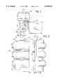
- FIG. 1is a side view of an outboard marine motor incorporating the oil distribution system of the present invention
- FIG. 2is a side view of an internal combustion engine incorporating the oil distribution system of the present invention
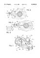
- FIG. 3is a sectional view taken along line 3--3 of FIG. 2 showing the oil passageways in relation to the crankshaft and the cylinder block;
- FIG. 4is a partial sectional view taken along line 4--4 of FIG. 3 showing one of the oil passageways;
- FIG. 5is a partial sectional view taken along line 5--5 of FIG. 3 showing one of the oil passageways;
- FIG. 6is a partial sectional view taken along line 6--6 of FIG. 4 showing one of the oil channels;
- FIG. 7is a partial perspective view showing the placement of oil on the engine components in accordance with the present invention.
- FIG. 8is a top view of an internal combustion engine of the second embodiment of the invention.
- FIG. 9is a partial sectional view taken along line 9--9 of FIG. 8 showing the oil passageways of the second embodiment of the invention in relation to the crankshaft and the cylinder block;
- FIG. 10is a partial sectional view taken along line 10--10 of FIG. 9 showing one of the oil passageways of the second embodiment of the invention.
- FIG. 11is a partial sectional view taken alone line 11--11 of FIG. 9 showing one of the oil passageways of the second embodiment of the invention.
- FIG. 1shows a marine outboard motor 10 as conventionally mounted to a boat 12.
- the outboard motor 10generally includes an internal combustion engine 14 that communicates with a submerged propeller 16 through a vertical drive train 18, such that the internal combustion engine 14 can provide the required force to rotate the propeller 16 and propel the boat 12.
- the internal combustion engine 20 of the first embodimentis a three-cylinder, two-cycle direct fuel injected (DFI) engine.
- the engine 20generally includes a cylinder block 22 and a crankcase cover 24 securely attached to the cylinder block 22.
- the engine 20further includes a crankshaft 26 and a bank of cylinders 28.
- the engine 20is mounted within the outboard motor 10 such that the crankshaft 26 extends along a vertical axis while the individual cylinders 28 each extend longitudinally along a generally horizontal axis.
- a piston 30(FIG. 7) is reciprocally movable within each of the cylinders 28 defined by the cylinder block 22. Each of the pistons 30 reciprocates along a horizontal axis within its respective cylinder 28 in a conventional manner.
- each of the pistons 30generally includes a piston head 32 surrounded by a piston ring 34.
- the piston ring 34interacts with the inside wall of the engine cylinder 28 to provide a seal between the piston head 32 and the engine cylinder 28.
- Each of the pistons 30includes a wrist pin 36 extending across its generally hollow interior 38.
- a connecting rod 40joins the piston 30 to the crankshaft 26.
- a first end 42 of the connecting rod 40surrounds the wrist pin 36.
- a first bearing assembly 44is positioned between the first end 42 of the connecting rod 40 and the wrist pin 36 such that the wrist pin 36 can freely rotate with respect to the first end 42 of the connecting rod 40.
- a second end 46 of the connecting rod 40surrounds a connecting portion 47 (FIG. 3) of the crankshaft 26.
- a second bearing assembly(not shown) is positioned between the second end 46 of the connecting rod 40 and the connecting portion 47 such that the crankshaft 26 can rotate with respect to the second end 46 of the connecting rod 40.
- the crankshaft 26includes a pair of counterweights 48, each of which are positioned on opposite sides of the connecting rod 40.
- the counterweights 48are sized to offset the inertial forces created by the reciprocating piston 30 in an effort to eliminate engine shaking in a conventional manner.
- the crankshaft 26is rotatably supported between the cylinder block 22 and the crankcase cover 24 by a series of main bearing assemblies 50.
- the crankshaft 26passes through each of the main bearing assemblies 50 such that when the main bearing assemblies 50 are secured between the cylinder block 22 and the crankcase cover 24, the main bearing assemblies 50 allow the crankshaft 26 to freely rotate with respect to the stationary cylinder block 22 and crankcase cover 24.
- Each of the main bearing assemblies 50is supported by a solid web portion 52 of the cylinder block 22.
- a series of corresponding web portionsare also formed on the crank case cover 24, such that each of the main bearing assemblies 50 is securely captured between the cylinder block 22 and the crankcase cover 24.
- the web portions 52separate and define a series of internal cavities 54 that are sized to permit the rotating movement of the crankshaft 26, including the counterweights 48 and the connecting rods 40.
- a corresponding set of internal cavities(not shown) is also formed in the crankcase cover 24 such that the crankshaft 26 can freely rotate without the counterweights 48 or connecting rods 40 contacting either the cylinder block 22 or the crankcase cover 24.
- each of the web portions 52generally includes a first face surface 58 and a second face surface 60.
- each of the face surfaces 58 and 60is a generally flat surface that defines a portion of an attachment surface 62 of the cylinder block 22.
- the attachment surface 62 of the cylinder block 22interacts with a similar flat attachment surface of the crankcase cover 24.
- a liquid gasket 63(FIG. 2) is applied between the attachment surfaces of the cylinder block 22 and the crankcase cover 24 to form a fluid tight seal therebetween.
- the first face surface 58 of the web portion 52is to the left of the crankshaft 26, while the second face surface 60 is on the right side of the crankshaft 26 when viewed as shown in FIG. 3.
- the cylinder block 22includes a series of oil passageways 64.
- the oil passageways 64are removed portions of the cylinder block 22 and each include an oil channel 66 formed in the first face surface 58 of the web portion 52 of the cylinder block 22.
- the oil channels 66are depressions or removed grooves formed in the otherwise flat first face surface 58, as shown in FIG. 6.
- each oil channel 66is generally semi-circular, although other configurations are contemplated as being within the scope of the invention.
- each oil channel 66is formed in the cylinder block 22, each one corresponding to one of the three cylinders 28.
- Each of the oil channels 66is generally perpendicular to the crankshaft 26 and extends from an inlet opening 67 spaced from the outer wall of the cylinder block 22 to an outlet opening 68.
- the outlet opening 68is formed in the inside wall 69 of the respective web portion 52 such that each oil channel 66 can communicate with the internal cavity 54 through the respective outlet opening 68.
- Each of the oil passageways 64is connected to a supply of oil through a fitting 70 and an oil supply line 72.
- oilis supplied through the oil lines 72 by a conventional low pressure diaphragm-type oil pump.
- the manner in which oil is supplied to the fittings 70could be accomplished by numerous oil pump arrangements.
- oil supplied through the oil lines 72can be supplied at a low pressure, such as approximately 10 psi in the preferred embodiment.
- oil flowing in the direction of arrow 74travels through the oil channel 66 until it reaches the outlet opening 68. Since the engine block 22 is typically mounted within the outboard motor 10 such that the crankshaft 26 extends along a vertical axis, oil reaching the outlet opening 68 falls in the direction shown by arrow 76 due to the force of gravity.
- crankshaft assembly 79As the oil is outwardly directed by the rotating counterweights 48, the oil comes into contact with the first bearing assembly 44 between the wrist pin 36 and the connecting rod 40. Additionally, as the crankshaft 26 rotates, oil exiting the outlet opening 68 directly coats the second bearing assembly between the crankshaft 26 and the connecting rod 40. In this manner, oil flowing through the oil passageway 64 and oil channel 66 is directly applied to the crankshaft assembly 79, including the crankshaft 26, the connecting rod 40, and the counterweight 48, such that the crankshaft assembly 79 can distribute the oil to lubricate the internal engine components.
- the oil channel 66be formed in the first face surface 58 on the left side of the crankshaft 26, rather than the second face surface 60 on the right side of the crankshaft. If the oil channel 66 was formed in the second face surface 60, the clockwise rotating counterweights 48 would direct a majority of the oil in the opposite direction away from the pistons 30 and into the crankcase cover 24. In addition, it is extremely important that the location of the outlet opening 68 be specifically positioned such that oil (arrow 76) is directly applied to the counterweight 48 in an optimal manner. For example, if the outlet opening 68 were located a greater distance from the main bearing assembly 50, the oil may not optimally contact the rotating counterweights 48 and the bearings between the connecting rod 40 and the crankshaft 26.
- a fluorescent dyewas mixed with the oil to determine the optimum position of the outlet openings 68.
- a fluorescent dyecalled "fluoro-dye", available from Corrosion Consultants, was mixed with conventional engine oil at a ratio of approximately 10:1 and the engine was operated for a test period of approximately 15 seconds.
- the crankshaft assembly 79 and the pistons 30were removed and examined under black light.
- the effectiveness of the outlet openings 68 positioncould be determined. This procedure was repeated numerous times until an optimal position of the outlet openings 68 was determined.
- the method of using the fluorescent dye to determine the optimum position of the outlet openings 68allows each engine to be configured according to the specific design characteristics of the engine itself.
- engine oilcan be directly applied through the oil channels 66 to the crankshaft assembly 79, including the crankshaft 26 and connecting rods 40, such that the movement of the counterweights 48 and the crankshaft 26 distributes oil into contact with the bearings positioned between the connecting rods 40, the pistons 30 and crankshaft 26.
- oilis directly applied to the engine components and the movement of the components themselves distributes the oil, unlike the conventional method of distributing oil in which the oil is distributed as a fine mist throughout the engine.
- FIGS. 8-11Shown in FIGS. 8-11 is a second embodiment of an internal combustion engine incorporating the oil lubrication system of the present invention.
- the internal combustion engine 80 of the second embodimentis a six-cylinder DFI engine.
- the six cylindersare arranged in a V configuration as is clearly shown in FIG. 8.
- the engine 80includes a cylinder block 82, a crankcase cover 84 and a pair of cylinder heads 86.
- the cylinder heads 86define the top of each of the cylinders 88, as shown in FIG. 9.
- FIG. 9As is best shown in FIG.
- each of the cylinders 88includes a piston 90 joined to a crankshaft assembly 91, including a crankshaft 92 and a plurality of connecting rods 94.
- Each of the connecting rods 94is connected to one of the pistons 90 by a wrist pin 96.
- the first end 98 of the connecting rod 94surrounds the wrist pin 96.
- a bearing assembly(not shown) is positioned between the first end 98 and the wrist pin 96 such that the first end 98 of the connecting rod 94 can rotate with respect to the wrist pin 96.
- a second end 100 of each connecting rod 94is connected to the crankshaft 92 and surrounds a bearing assembly (not shown), such that the second end 100 of the connecting rod 94 can rotate with respect with the crankshaft 92.
- the crankshaft 92is rotatably supported by a pair of main bearing assemblies 102 that are received in the web portions 104 of the cylinder block 82.
- the main bearing assemblies 102allow the crankshaft 92 to rotate with respect to the cylinder block 82 and the crankcase cover 84.
- the crankshaft assembly 91includes a pair of counterweights 106 positioned on opposite axial ends of the crankshaft 92.
- the crankshaft assembly 91 of the second embodimentdoes not include counterweights which can be used to distribute oil into contact with the wrist pin 96 on each of the pistons 90. For this reason, the oil distribution system in the six-cylinder internal combustion engine 80 differs slightly from the oil distribution system in the three-cylinder internal combustion engine 20.
- the cylinder block 82includes a series of oil passageways 108 that extend between the exterior of the cylinder block 82 and the individual cylinders 88.
- each of the oil passageways 108includes a fitting 70 connected to the oil line 72, such that oil is supplied to each of the cylinders 88 from a low pressure oil pump. After the oil passes through the fitting 70, the oil enters the oil passageway 108 and travels to an outlet opening 110 formed in the bottom wall 111 of the cylinder.
- each of the outlet openings 110is positioned above the corresponding connecting rod 94 for each cylinder 88, such that oil exiting the outlet opening 110 falls downward onto the connecting rod 94 as shown by arrow 112.
- the engine 80is mounted such that the crankshaft is vertically disposed as shown in FIG. 9.
- the connecting rod 94due to the influence of gravity. Since each of the connecting rods 94 is reciprocating at a high rate of speed as shown by arrow 114, the oil that falls into contact with the connecting rod 94 is thrown throughout the cylinder 88 below the piston 90.
- each of the outlet openings 110must be positioned above one of the connecting rods 94, such that oil is forced by gravity into contact with the connecting rod 94.
- the movement of the crankshaft assembly 91, specifically the connecting rods 94acts to distribute the oil to lubricate the bearings between the connecting rod 94 and either the piston 90 or the crankshaft 92.
- a fluorescent dyewas used in determining the optimum position for the outlet openings 110. By injecting the fluorescent dye into the oil and allowing the engine to operate for a brief period of time, the dispersion of oil within the engine could be determined.
- an oil distribution systemwhich uses the components within the engine, specifically the crankshaft and connecting rods, to disperse a coating of lubricating oil into contact with the bearings of the engine.
- the engine componentsthemselves are used to distribute the oil, without requiring a fine mist of oil to be entrained with the fuel supply.
- the oil distribution system of the present inventionis particularly desirable for use in a direct fuel injected (DFI) engine.
- DFIdirect fuel injected
Landscapes
- Engineering & Computer Science (AREA)
- Mechanical Engineering (AREA)
- General Engineering & Computer Science (AREA)
- Chemical & Material Sciences (AREA)
- Combustion & Propulsion (AREA)
- Lubrication Of Internal Combustion Engines (AREA)
Abstract
Description
Claims (7)
Priority Applications (1)
| Application Number | Priority Date | Filing Date | Title |
|---|---|---|---|
| US09/371,996US6138634A (en) | 1997-12-10 | 1999-08-11 | Oil lubrication system for an internal combustion engine |
Applications Claiming Priority (2)
| Application Number | Priority Date | Filing Date | Title |
|---|---|---|---|
| US08/988,156US5950588A (en) | 1997-12-10 | 1997-12-10 | Oil lubrication system for an internal combustion engine |
| US09/371,996US6138634A (en) | 1997-12-10 | 1999-08-11 | Oil lubrication system for an internal combustion engine |
Related Parent Applications (1)
| Application Number | Title | Priority Date | Filing Date |
|---|---|---|---|
| US08/988,156ContinuationUS5950588A (en) | 1997-12-10 | 1997-12-10 | Oil lubrication system for an internal combustion engine |
Publications (1)
| Publication Number | Publication Date |
|---|---|
| US6138634Atrue US6138634A (en) | 2000-10-31 |
Family
ID=25533899
Family Applications (2)
| Application Number | Title | Priority Date | Filing Date |
|---|---|---|---|
| US08/988,156Expired - LifetimeUS5950588A (en) | 1997-12-10 | 1997-12-10 | Oil lubrication system for an internal combustion engine |
| US09/371,996Expired - LifetimeUS6138634A (en) | 1997-12-10 | 1999-08-11 | Oil lubrication system for an internal combustion engine |
Family Applications Before (1)
| Application Number | Title | Priority Date | Filing Date |
|---|---|---|---|
| US08/988,156Expired - LifetimeUS5950588A (en) | 1997-12-10 | 1997-12-10 | Oil lubrication system for an internal combustion engine |
Country Status (1)
| Country | Link |
|---|---|
| US (2) | US5950588A (en) |
Cited By (7)
| Publication number | Priority date | Publication date | Assignee | Title |
|---|---|---|---|---|
| US6450297B1 (en)* | 1999-06-25 | 2002-09-17 | Samsung Kwangju Electronics Co., Ltd. | Hermetic compressor |
| US6651779B2 (en)* | 2000-09-06 | 2003-11-25 | Eaton Corporation | Valve lift control unit with simplified lubrication |
| US6652338B2 (en)* | 2001-08-29 | 2003-11-25 | Yamaha Marine Kabushiki Kaisha | Lubricant drain arrangement for multi-cylinder internal combustion engine |
| US20080035101A1 (en)* | 2004-04-22 | 2008-02-14 | Wacker Construction Equipment Ag | Oil Supply For An Internal Combustion Engine |
| US8074355B1 (en) | 2007-11-08 | 2011-12-13 | Brunswick Corporation | Method for manufacturing a connecting rod for an engine |
| US8757028B2 (en) | 2010-12-23 | 2014-06-24 | Brp Us Inc. | Crankshaft for a two-stroke engine |
| US10533467B1 (en) | 2018-06-28 | 2020-01-14 | Brunswick Corporation | Outboard motors having idler-driven lubricating pump |
Families Citing this family (5)
| Publication number | Priority date | Publication date | Assignee | Title |
|---|---|---|---|---|
| US5950588A (en)* | 1997-12-10 | 1999-09-14 | Brunswick Corporation | Oil lubrication system for an internal combustion engine |
| US6477885B1 (en)* | 1998-12-25 | 2002-11-12 | Nsk Ltd. | Lubricant applying system for a rolling bearing |
| US6845744B2 (en)* | 2002-01-22 | 2005-01-25 | Bombardier Recreational Products Inc. | Method and apparatus for inter-cylinder lubrication transfer in a multi-cylinder internal combustion engine |
| US8746068B2 (en)* | 2010-04-16 | 2014-06-10 | U.E. Systems, Inc. | Ultrasonically controllable grease dispensing tool |
| US11313409B1 (en)* | 2019-12-19 | 2022-04-26 | Brunswick Corporation | Crankshaft and cranktrain for internal combustion engine |
Citations (9)
| Publication number | Priority date | Publication date | Assignee | Title |
|---|---|---|---|---|
| US4493661A (en)* | 1980-07-12 | 1985-01-15 | Yamaha Hatsudoki Kabushiki Kaisha | Outboard engine |
| US4926814A (en)* | 1989-07-12 | 1990-05-22 | Tecumseh Products Company | Crankcase breather and lubrication oil system for an internal combustion engine |
| US5570662A (en)* | 1993-07-27 | 1996-11-05 | Outboard Marine Corporation | Internal combustion engine with lubricating oil supply system |
| US5755194A (en)* | 1995-07-06 | 1998-05-26 | Tecumseh Products Company | Overhead cam engine with dry sump lubrication system |
| US5950588A (en)* | 1997-12-10 | 1999-09-14 | Brunswick Corporation | Oil lubrication system for an internal combustion engine |
| US5960764A (en)* | 1997-03-03 | 1999-10-05 | Kioritz Corporation | Four-stroke internal combustion engine |
| US5975042A (en)* | 1997-06-26 | 1999-11-02 | Ishiakawjima-Shibaura Machinery Co., Ltd. | Oil supply apparatus of a four-stroke-cycle engine |
| US6058900A (en)* | 1999-07-20 | 2000-05-09 | Brunswick Corporation | Internal combustion engine with improved cylinder wall lubrication system |
| US6067952A (en)* | 1998-12-10 | 2000-05-30 | Brunswick Corporation | Cylinder bore lubrication with residual oil |
Family Cites Families (10)
| Publication number | Priority date | Publication date | Assignee | Title |
|---|---|---|---|---|
| US1612372A (en)* | 1925-07-09 | 1926-12-28 | August H Gussman | Lubricating apparatus |
| US2728412A (en)* | 1949-08-17 | 1955-12-27 | Hartford Nat Bank & Trust Co | Motor oiling system |
| US3672172A (en)* | 1971-03-15 | 1972-06-27 | Gary L Hammond | Simplified supercharged internal combustion engine with emissions control |
| DE3146799C1 (en)* | 1981-11-26 | 1983-06-01 | Audi Nsu Auto Union Ag, 7107 Neckarsulm | Reciprocating internal combustion engine |
| GB2115484B (en)* | 1982-02-25 | 1985-01-16 | Massey Ferguson Perkins Ltd | The sump |
| US4741303A (en)* | 1986-10-14 | 1988-05-03 | Tecumseh Products Company | Combination counterbalance and oil slinger for horizontal shaft engines |
| US5513608A (en)* | 1992-08-26 | 1996-05-07 | Sanshin Kogyo Kabushiki Kaisha | Two cycle engine lubricating system |
| US5709185A (en)* | 1994-11-29 | 1998-01-20 | Ishikawajima-Shibaura Machinery Co., Ltd. | Lubricating system for four-stroke-cycle engine |
| US5472360A (en)* | 1995-01-03 | 1995-12-05 | Brunswick Corporation | Oil containment means for outboard motor |
| JPH08303238A (en)* | 1995-05-11 | 1996-11-19 | Ishikawajima Shibaura Mach Co Ltd | Four-cycle engine |
- 1997
- 1997-12-10USUS08/988,156patent/US5950588A/ennot_activeExpired - Lifetime
- 1999
- 1999-08-11USUS09/371,996patent/US6138634A/ennot_activeExpired - Lifetime
Patent Citations (9)
| Publication number | Priority date | Publication date | Assignee | Title |
|---|---|---|---|---|
| US4493661A (en)* | 1980-07-12 | 1985-01-15 | Yamaha Hatsudoki Kabushiki Kaisha | Outboard engine |
| US4926814A (en)* | 1989-07-12 | 1990-05-22 | Tecumseh Products Company | Crankcase breather and lubrication oil system for an internal combustion engine |
| US5570662A (en)* | 1993-07-27 | 1996-11-05 | Outboard Marine Corporation | Internal combustion engine with lubricating oil supply system |
| US5755194A (en)* | 1995-07-06 | 1998-05-26 | Tecumseh Products Company | Overhead cam engine with dry sump lubrication system |
| US5960764A (en)* | 1997-03-03 | 1999-10-05 | Kioritz Corporation | Four-stroke internal combustion engine |
| US5975042A (en)* | 1997-06-26 | 1999-11-02 | Ishiakawjima-Shibaura Machinery Co., Ltd. | Oil supply apparatus of a four-stroke-cycle engine |
| US5950588A (en)* | 1997-12-10 | 1999-09-14 | Brunswick Corporation | Oil lubrication system for an internal combustion engine |
| US6067952A (en)* | 1998-12-10 | 2000-05-30 | Brunswick Corporation | Cylinder bore lubrication with residual oil |
| US6058900A (en)* | 1999-07-20 | 2000-05-09 | Brunswick Corporation | Internal combustion engine with improved cylinder wall lubrication system |
Cited By (8)
| Publication number | Priority date | Publication date | Assignee | Title |
|---|---|---|---|---|
| US6450297B1 (en)* | 1999-06-25 | 2002-09-17 | Samsung Kwangju Electronics Co., Ltd. | Hermetic compressor |
| US6651779B2 (en)* | 2000-09-06 | 2003-11-25 | Eaton Corporation | Valve lift control unit with simplified lubrication |
| US6652338B2 (en)* | 2001-08-29 | 2003-11-25 | Yamaha Marine Kabushiki Kaisha | Lubricant drain arrangement for multi-cylinder internal combustion engine |
| US20080035101A1 (en)* | 2004-04-22 | 2008-02-14 | Wacker Construction Equipment Ag | Oil Supply For An Internal Combustion Engine |
| US7753024B2 (en)* | 2004-04-22 | 2010-07-13 | Wacker Neuson Se | Oil supply for an internal combustion engine |
| US8074355B1 (en) | 2007-11-08 | 2011-12-13 | Brunswick Corporation | Method for manufacturing a connecting rod for an engine |
| US8757028B2 (en) | 2010-12-23 | 2014-06-24 | Brp Us Inc. | Crankshaft for a two-stroke engine |
| US10533467B1 (en) | 2018-06-28 | 2020-01-14 | Brunswick Corporation | Outboard motors having idler-driven lubricating pump |
Also Published As
| Publication number | Publication date |
|---|---|
| US5950588A (en) | 1999-09-14 |
Similar Documents
| Publication | Publication Date | Title |
|---|---|---|
| US6138634A (en) | Oil lubrication system for an internal combustion engine | |
| US3528394A (en) | Internal combustion engine | |
| US4945864A (en) | Two cycle engine piston lubrication | |
| US6145488A (en) | Reduced volume scavenging system for two cycle engines | |
| US5771849A (en) | Internal combustion engine with crankcase pressure barrier | |
| US5513608A (en) | Two cycle engine lubricating system | |
| JP2694907B2 (en) | 2 cycle engine | |
| CA2674151C (en) | Two-stroke engine | |
| US6536385B1 (en) | Piston ring | |
| JPH06229219A (en) | Lubricating device for two-cycle engine | |
| US5396867A (en) | Two-cycle engine | |
| US6644263B2 (en) | Engine with dry sump lubrication | |
| US6792910B2 (en) | Oil injection system | |
| US3800753A (en) | Drainage system for internal combustion engine having a horizontally disposed crankshaft | |
| US3753425A (en) | Two stroke internal combustion engines | |
| JPS63280810A (en) | Piston-pin lubricating device for two cycle engine | |
| US5797359A (en) | Stepped piston two-cycle internal combustion engine | |
| EP0937920A1 (en) | Bearing arrangement for a piston pin | |
| MX2008015124A (en) | Two-stroke internal combustion chamber with two pistons per cylinder. | |
| JP3487534B2 (en) | Engine lubrication structure | |
| US20010040346A1 (en) | Piston ring assembly | |
| JPH0123650B2 (en) | ||
| JPS5933843Y2 (en) | 2 cylinder 2 cycle engine | |
| JPH07656Y2 (en) | Lubricator for 2-cycle engine | |
| JPH06212931A (en) | Oil feeder for two-cycle engine |
Legal Events
| Date | Code | Title | Description |
|---|---|---|---|
| STCF | Information on status: patent grant | Free format text:PATENTED CASE | |
| FPAY | Fee payment | Year of fee payment:4 | |
| FPAY | Fee payment | Year of fee payment:8 | |
| AS | Assignment | Owner name:JPMORGAN CHASE BANK, N.A., TEXAS Free format text:SECURITY AGREEMENT;ASSIGNORS:BRUNSWICK CORPORATION;TRITON BOAT COMPANY, L.P.;ATTWOOD CORPORATION;AND OTHERS;REEL/FRAME:022092/0365 Effective date:20081219 Owner name:JPMORGAN CHASE BANK, N.A.,TEXAS Free format text:SECURITY AGREEMENT;ASSIGNORS:BRUNSWICK CORPORATION;TRITON BOAT COMPANY, L.P.;ATTWOOD CORPORATION;AND OTHERS;REEL/FRAME:022092/0365 Effective date:20081219 | |
| AS | Assignment | Owner name:THE BANK OF NEW YORK MELLON TRUST COMPANY, N.A., I Free format text:SECURITY AGREEMENT;ASSIGNORS:BRUNSWICK CORPORATION;ATTWOOD CORPORATION;BOSTON WHALER, INC.;AND OTHERS;REEL/FRAME:023180/0493 Effective date:20090814 Owner name:THE BANK OF NEW YORK MELLON TRUST COMPANY, N.A.,IL Free format text:SECURITY AGREEMENT;ASSIGNORS:BRUNSWICK CORPORATION;ATTWOOD CORPORATION;BOSTON WHALER, INC.;AND OTHERS;REEL/FRAME:023180/0493 Effective date:20090814 | |
| AS | Assignment | Owner name:LAND 'N' SEA DISTRIBUTING, INC., FLORIDA Free format text:RELEASE BY SECURED PARTY;ASSIGNOR:JPMORGAN CHASE BANK, N.A., AS ADMINISTRATIVE AGENT;REEL/FRAME:026026/0001 Effective date:20110321 Owner name:LUND BOAT COMPANY, MINNESOTA Free format text:RELEASE BY SECURED PARTY;ASSIGNOR:JPMORGAN CHASE BANK, N.A., AS ADMINISTRATIVE AGENT;REEL/FRAME:026026/0001 Effective date:20110321 Owner name:BRUNSWICK CORPORATION, ILLINOIS Free format text:RELEASE BY SECURED PARTY;ASSIGNOR:JPMORGAN CHASE BANK, N.A., AS ADMINISTRATIVE AGENT;REEL/FRAME:026026/0001 Effective date:20110321 Owner name:BRUNSWICK COMMERICAL & GOVERNMENT PRODUCTS, INC., Free format text:RELEASE BY SECURED PARTY;ASSIGNOR:JPMORGAN CHASE BANK, N.A., AS ADMINISTRATIVE AGENT;REEL/FRAME:026026/0001 Effective date:20110321 Owner name:BRUNSWICK LEISURE BOAT COMPANY, LLC, INDIANA Free format text:RELEASE BY SECURED PARTY;ASSIGNOR:JPMORGAN CHASE BANK, N.A., AS ADMINISTRATIVE AGENT;REEL/FRAME:026026/0001 Effective date:20110321 Owner name:ATTWOOD CORPORATION, MICHIGAN Free format text:RELEASE BY SECURED PARTY;ASSIGNOR:JPMORGAN CHASE BANK, N.A., AS ADMINISTRATIVE AGENT;REEL/FRAME:026026/0001 Effective date:20110321 Owner name:TRITON BOAT COMPANY, L.P., TENNESSEE Free format text:RELEASE BY SECURED PARTY;ASSIGNOR:JPMORGAN CHASE BANK, N.A., AS ADMINISTRATIVE AGENT;REEL/FRAME:026026/0001 Effective date:20110321 Owner name:BRUNSWICK BOWLING & BILLIARDS CORPORATION, ILLINOI Free format text:RELEASE BY SECURED PARTY;ASSIGNOR:JPMORGAN CHASE BANK, N.A., AS ADMINISTRATIVE AGENT;REEL/FRAME:026026/0001 Effective date:20110321 Owner name:BRUNSWICK FAMILY BOAT CO. INC., WASHINGTON Free format text:RELEASE BY SECURED PARTY;ASSIGNOR:JPMORGAN CHASE BANK, N.A., AS ADMINISTRATIVE AGENT;REEL/FRAME:026026/0001 Effective date:20110321 Owner name:BOSTON WHALER, INC., FLORIDA Free format text:RELEASE BY SECURED PARTY;ASSIGNOR:JPMORGAN CHASE BANK, N.A., AS ADMINISTRATIVE AGENT;REEL/FRAME:026026/0001 Effective date:20110321 | |
| AS | Assignment | Owner name:JPMORGAN CHASE BANK, N.A., AS ADMINISTRATIVE AGENT Free format text:SECURITY AGREEMENT;ASSIGNORS:BRUNSWICK CORPORATION;ATTWOOD CORPORATION;BOSTON WHALER, INC.;AND OTHERS;REEL/FRAME:026072/0239 Effective date:20110321 | |
| FPAY | Fee payment | Year of fee payment:12 | |
| AS | Assignment | Owner name:BRUNSWICK CORPORATION, ILLINOIS Free format text:RELEASE BY SECURED PARTY;ASSIGNOR:THE BANK OF NEW YORK MELLON;REEL/FRAME:031973/0242 Effective date:20130717 | |
| AS | Assignment | Owner name:LAND 'N' SEA DISTRIBUTING, INC., ILLINOIS Free format text:RELEASE BY SECURED PARTY;ASSIGNOR:JPMORGAN CHASE BANK, N.A.;REEL/FRAME:034794/0300 Effective date:20141226 Owner name:BOSTON WHALER, INC., ILLINOIS Free format text:RELEASE BY SECURED PARTY;ASSIGNOR:JPMORGAN CHASE BANK, N.A.;REEL/FRAME:034794/0300 Effective date:20141226 Owner name:BRUNSWICK BOWLING & BILLIARDS CORPORATION, ILLINOI Free format text:RELEASE BY SECURED PARTY;ASSIGNOR:JPMORGAN CHASE BANK, N.A.;REEL/FRAME:034794/0300 Effective date:20141226 Owner name:BRUNSWICK CORPORATION, ILLINOIS Free format text:RELEASE BY SECURED PARTY;ASSIGNOR:JPMORGAN CHASE BANK, N.A.;REEL/FRAME:034794/0300 Effective date:20141226 Owner name:BRUNSWICK LEISURE BOAT COMPANY, LLC, ILLINOIS Free format text:RELEASE BY SECURED PARTY;ASSIGNOR:JPMORGAN CHASE BANK, N.A.;REEL/FRAME:034794/0300 Effective date:20141226 Owner name:ATTWOOD CORPORATION, ILLINOIS Free format text:RELEASE BY SECURED PARTY;ASSIGNOR:JPMORGAN CHASE BANK, N.A.;REEL/FRAME:034794/0300 Effective date:20141226 Owner name:BRUNSWICK FAMILY BOAT CO. INC., ILLINOIS Free format text:RELEASE BY SECURED PARTY;ASSIGNOR:JPMORGAN CHASE BANK, N.A.;REEL/FRAME:034794/0300 Effective date:20141226 Owner name:BRUNSWICK COMMERCIAL & GOVERNMENT PRODUCTS, INC., Free format text:RELEASE BY SECURED PARTY;ASSIGNOR:JPMORGAN CHASE BANK, N.A.;REEL/FRAME:034794/0300 Effective date:20141226 Owner name:LUND BOAT COMPANY, ILLINOIS Free format text:RELEASE BY SECURED PARTY;ASSIGNOR:JPMORGAN CHASE BANK, N.A.;REEL/FRAME:034794/0300 Effective date:20141226 |