US6138466A - System for cooling electric vehicle batteries - Google Patents
System for cooling electric vehicle batteriesDownload PDFInfo
- Publication number
- US6138466A US6138466AUS09/190,543US19054398AUS6138466AUS 6138466 AUS6138466 AUS 6138466AUS 19054398 AUS19054398 AUS 19054398AUS 6138466 AUS6138466 AUS 6138466A
- Authority
- US
- United States
- Prior art keywords
- refrigerant
- heat
- flow
- heat exchanger
- temperature
- Prior art date
- Legal status (The legal status is an assumption and is not a legal conclusion. Google has not performed a legal analysis and makes no representation as to the accuracy of the status listed.)
- Expired - Lifetime
Links
Images


Classifications
- F—MECHANICAL ENGINEERING; LIGHTING; HEATING; WEAPONS; BLASTING
- F25—REFRIGERATION OR COOLING; COMBINED HEATING AND REFRIGERATION SYSTEMS; HEAT PUMP SYSTEMS; MANUFACTURE OR STORAGE OF ICE; LIQUEFACTION SOLIDIFICATION OF GASES
- F25B—REFRIGERATION MACHINES, PLANTS OR SYSTEMS; COMBINED HEATING AND REFRIGERATION SYSTEMS; HEAT PUMP SYSTEMS
- F25B13/00—Compression machines, plants or systems, with reversible cycle
- B—PERFORMING OPERATIONS; TRANSPORTING
- B60—VEHICLES IN GENERAL
- B60H—ARRANGEMENTS OF HEATING, COOLING, VENTILATING OR OTHER AIR-TREATING DEVICES SPECIALLY ADAPTED FOR PASSENGER OR GOODS SPACES OF VEHICLES
- B60H1/00—Heating, cooling or ventilating [HVAC] devices
- B60H1/00271—HVAC devices specially adapted for particular vehicle parts or components and being connected to the vehicle HVAC unit
- B60H1/00278—HVAC devices specially adapted for particular vehicle parts or components and being connected to the vehicle HVAC unit for the battery
- B—PERFORMING OPERATIONS; TRANSPORTING
- B60—VEHICLES IN GENERAL
- B60H—ARRANGEMENTS OF HEATING, COOLING, VENTILATING OR OTHER AIR-TREATING DEVICES SPECIALLY ADAPTED FOR PASSENGER OR GOODS SPACES OF VEHICLES
- B60H1/00—Heating, cooling or ventilating [HVAC] devices
- B60H1/00357—Air-conditioning arrangements specially adapted for particular vehicles
- B60H1/00385—Air-conditioning arrangements specially adapted for particular vehicles for vehicles having an electrical drive, e.g. hybrid or fuel cell
- B60H1/00392—Air-conditioning arrangements specially adapted for particular vehicles for vehicles having an electrical drive, e.g. hybrid or fuel cell for electric vehicles having only electric drive means
- B—PERFORMING OPERATIONS; TRANSPORTING
- B60—VEHICLES IN GENERAL
- B60H—ARRANGEMENTS OF HEATING, COOLING, VENTILATING OR OTHER AIR-TREATING DEVICES SPECIALLY ADAPTED FOR PASSENGER OR GOODS SPACES OF VEHICLES
- B60H1/00—Heating, cooling or ventilating [HVAC] devices
- B60H1/00642—Control systems or circuits; Control members or indication devices for heating, cooling or ventilating devices
- B60H1/00814—Control systems or circuits characterised by their output, for controlling particular components of the heating, cooling or ventilating installation
- B60H1/00878—Control systems or circuits characterised by their output, for controlling particular components of the heating, cooling or ventilating installation the components being temperature regulating devices
- B60H1/00899—Controlling the flow of liquid in a heat pump system
- B60H1/00907—Controlling the flow of liquid in a heat pump system where the flow direction of the refrigerant changes and an evaporator becomes condenser
- B—PERFORMING OPERATIONS; TRANSPORTING
- B60—VEHICLES IN GENERAL
- B60L—PROPULSION OF ELECTRICALLY-PROPELLED VEHICLES; SUPPLYING ELECTRIC POWER FOR AUXILIARY EQUIPMENT OF ELECTRICALLY-PROPELLED VEHICLES; ELECTRODYNAMIC BRAKE SYSTEMS FOR VEHICLES IN GENERAL; MAGNETIC SUSPENSION OR LEVITATION FOR VEHICLES; MONITORING OPERATING VARIABLES OF ELECTRICALLY-PROPELLED VEHICLES; ELECTRIC SAFETY DEVICES FOR ELECTRICALLY-PROPELLED VEHICLES
- B60L3/00—Electric devices on electrically-propelled vehicles for safety purposes; Monitoring operating variables, e.g. speed, deceleration or energy consumption
- B60L3/0023—Detecting, eliminating, remedying or compensating for drive train abnormalities, e.g. failures within the drive train
- B60L3/0046—Detecting, eliminating, remedying or compensating for drive train abnormalities, e.g. failures within the drive train relating to electric energy storage systems, e.g. batteries or capacitors
- B—PERFORMING OPERATIONS; TRANSPORTING
- B60—VEHICLES IN GENERAL
- B60L—PROPULSION OF ELECTRICALLY-PROPELLED VEHICLES; SUPPLYING ELECTRIC POWER FOR AUXILIARY EQUIPMENT OF ELECTRICALLY-PROPELLED VEHICLES; ELECTRODYNAMIC BRAKE SYSTEMS FOR VEHICLES IN GENERAL; MAGNETIC SUSPENSION OR LEVITATION FOR VEHICLES; MONITORING OPERATING VARIABLES OF ELECTRICALLY-PROPELLED VEHICLES; ELECTRIC SAFETY DEVICES FOR ELECTRICALLY-PROPELLED VEHICLES
- B60L58/00—Methods or circuit arrangements for monitoring or controlling batteries or fuel cells, specially adapted for electric vehicles
- B60L58/10—Methods or circuit arrangements for monitoring or controlling batteries or fuel cells, specially adapted for electric vehicles for monitoring or controlling batteries
- B60L58/24—Methods or circuit arrangements for monitoring or controlling batteries or fuel cells, specially adapted for electric vehicles for monitoring or controlling batteries for controlling the temperature of batteries
- B60L58/26—Methods or circuit arrangements for monitoring or controlling batteries or fuel cells, specially adapted for electric vehicles for monitoring or controlling batteries for controlling the temperature of batteries by cooling
- F—MECHANICAL ENGINEERING; LIGHTING; HEATING; WEAPONS; BLASTING
- F25—REFRIGERATION OR COOLING; COMBINED HEATING AND REFRIGERATION SYSTEMS; HEAT PUMP SYSTEMS; MANUFACTURE OR STORAGE OF ICE; LIQUEFACTION SOLIDIFICATION OF GASES
- F25B—REFRIGERATION MACHINES, PLANTS OR SYSTEMS; COMBINED HEATING AND REFRIGERATION SYSTEMS; HEAT PUMP SYSTEMS
- F25B41/00—Fluid-circulation arrangements
- F25B41/30—Expansion means; Dispositions thereof
- F25B41/31—Expansion valves
- F25B41/34—Expansion valves with the valve member being actuated by electric means, e.g. by piezoelectric actuators
- H—ELECTRICITY
- H01—ELECTRIC ELEMENTS
- H01M—PROCESSES OR MEANS, e.g. BATTERIES, FOR THE DIRECT CONVERSION OF CHEMICAL ENERGY INTO ELECTRICAL ENERGY
- H01M10/00—Secondary cells; Manufacture thereof
- H01M10/60—Heating or cooling; Temperature control
- H01M10/61—Types of temperature control
- H01M10/613—Cooling or keeping cold
- H—ELECTRICITY
- H01—ELECTRIC ELEMENTS
- H01M—PROCESSES OR MEANS, e.g. BATTERIES, FOR THE DIRECT CONVERSION OF CHEMICAL ENERGY INTO ELECTRICAL ENERGY
- H01M10/00—Secondary cells; Manufacture thereof
- H01M10/60—Heating or cooling; Temperature control
- H01M10/62—Heating or cooling; Temperature control specially adapted for specific applications
- H01M10/625—Vehicles
- H—ELECTRICITY
- H01—ELECTRIC ELEMENTS
- H01M—PROCESSES OR MEANS, e.g. BATTERIES, FOR THE DIRECT CONVERSION OF CHEMICAL ENERGY INTO ELECTRICAL ENERGY
- H01M10/00—Secondary cells; Manufacture thereof
- H01M10/60—Heating or cooling; Temperature control
- H01M10/63—Control systems
- H—ELECTRICITY
- H01—ELECTRIC ELEMENTS
- H01M—PROCESSES OR MEANS, e.g. BATTERIES, FOR THE DIRECT CONVERSION OF CHEMICAL ENERGY INTO ELECTRICAL ENERGY
- H01M10/00—Secondary cells; Manufacture thereof
- H01M10/60—Heating or cooling; Temperature control
- H01M10/65—Means for temperature control structurally associated with the cells
- H01M10/656—Means for temperature control structurally associated with the cells characterised by the type of heat-exchange fluid
- H01M10/6567—Liquids
- H01M10/6568—Liquids characterised by flow circuits, e.g. loops, located externally to the cells or cell casings
- H—ELECTRICITY
- H01—ELECTRIC ELEMENTS
- H01M—PROCESSES OR MEANS, e.g. BATTERIES, FOR THE DIRECT CONVERSION OF CHEMICAL ENERGY INTO ELECTRICAL ENERGY
- H01M10/00—Secondary cells; Manufacture thereof
- H01M10/60—Heating or cooling; Temperature control
- H01M10/66—Heat-exchange relationships between the cells and other systems, e.g. central heating systems or fuel cells
- H01M10/663—Heat-exchange relationships between the cells and other systems, e.g. central heating systems or fuel cells the system being an air-conditioner or an engine
- B—PERFORMING OPERATIONS; TRANSPORTING
- B60—VEHICLES IN GENERAL
- B60H—ARRANGEMENTS OF HEATING, COOLING, VENTILATING OR OTHER AIR-TREATING DEVICES SPECIALLY ADAPTED FOR PASSENGER OR GOODS SPACES OF VEHICLES
- B60H1/00—Heating, cooling or ventilating [HVAC] devices
- B60H1/00271—HVAC devices specially adapted for particular vehicle parts or components and being connected to the vehicle HVAC unit
- B60H2001/00307—Component temperature regulation using a liquid flow
- B—PERFORMING OPERATIONS; TRANSPORTING
- B60—VEHICLES IN GENERAL
- B60H—ARRANGEMENTS OF HEATING, COOLING, VENTILATING OR OTHER AIR-TREATING DEVICES SPECIALLY ADAPTED FOR PASSENGER OR GOODS SPACES OF VEHICLES
- B60H1/00—Heating, cooling or ventilating [HVAC] devices
- B60H1/00642—Control systems or circuits; Control members or indication devices for heating, cooling or ventilating devices
- B60H1/00814—Control systems or circuits characterised by their output, for controlling particular components of the heating, cooling or ventilating installation
- B60H1/00878—Control systems or circuits characterised by their output, for controlling particular components of the heating, cooling or ventilating installation the components being temperature regulating devices
- B60H2001/00935—Control systems or circuits characterised by their output, for controlling particular components of the heating, cooling or ventilating installation the components being temperature regulating devices comprising four way valves for controlling the fluid direction
- B—PERFORMING OPERATIONS; TRANSPORTING
- B60—VEHICLES IN GENERAL
- B60K—ARRANGEMENT OR MOUNTING OF PROPULSION UNITS OR OF TRANSMISSIONS IN VEHICLES; ARRANGEMENT OR MOUNTING OF PLURAL DIVERSE PRIME-MOVERS IN VEHICLES; AUXILIARY DRIVES FOR VEHICLES; INSTRUMENTATION OR DASHBOARDS FOR VEHICLES; ARRANGEMENTS IN CONNECTION WITH COOLING, AIR INTAKE, GAS EXHAUST OR FUEL SUPPLY OF PROPULSION UNITS IN VEHICLES
- B60K1/00—Arrangement or mounting of electrical propulsion units
- B60K2001/003—Arrangement or mounting of electrical propulsion units with means for cooling the electrical propulsion units
- B60K2001/005—Arrangement or mounting of electrical propulsion units with means for cooling the electrical propulsion units the electric storage means
- F—MECHANICAL ENGINEERING; LIGHTING; HEATING; WEAPONS; BLASTING
- F25—REFRIGERATION OR COOLING; COMBINED HEATING AND REFRIGERATION SYSTEMS; HEAT PUMP SYSTEMS; MANUFACTURE OR STORAGE OF ICE; LIQUEFACTION SOLIDIFICATION OF GASES
- F25B—REFRIGERATION MACHINES, PLANTS OR SYSTEMS; COMBINED HEATING AND REFRIGERATION SYSTEMS; HEAT PUMP SYSTEMS
- F25B2313/00—Compression machines, plants or systems with reversible cycle not otherwise provided for
- F25B2313/023—Compression machines, plants or systems with reversible cycle not otherwise provided for using multiple indoor units
- F—MECHANICAL ENGINEERING; LIGHTING; HEATING; WEAPONS; BLASTING
- F25—REFRIGERATION OR COOLING; COMBINED HEATING AND REFRIGERATION SYSTEMS; HEAT PUMP SYSTEMS; MANUFACTURE OR STORAGE OF ICE; LIQUEFACTION SOLIDIFICATION OF GASES
- F25B—REFRIGERATION MACHINES, PLANTS OR SYSTEMS; COMBINED HEATING AND REFRIGERATION SYSTEMS; HEAT PUMP SYSTEMS
- F25B43/00—Arrangements for separating or purifying gases or liquids; Arrangements for vaporising the residuum of liquid refrigerant, e.g. by heat
- F25B43/003—Filters
- Y—GENERAL TAGGING OF NEW TECHNOLOGICAL DEVELOPMENTS; GENERAL TAGGING OF CROSS-SECTIONAL TECHNOLOGIES SPANNING OVER SEVERAL SECTIONS OF THE IPC; TECHNICAL SUBJECTS COVERED BY FORMER USPC CROSS-REFERENCE ART COLLECTIONS [XRACs] AND DIGESTS
- Y02—TECHNOLOGIES OR APPLICATIONS FOR MITIGATION OR ADAPTATION AGAINST CLIMATE CHANGE
- Y02B—CLIMATE CHANGE MITIGATION TECHNOLOGIES RELATED TO BUILDINGS, e.g. HOUSING, HOUSE APPLIANCES OR RELATED END-USER APPLICATIONS
- Y02B30/00—Energy efficient heating, ventilation or air conditioning [HVAC]
- Y02B30/70—Efficient control or regulation technologies, e.g. for control of refrigerant flow, motor or heating
- Y—GENERAL TAGGING OF NEW TECHNOLOGICAL DEVELOPMENTS; GENERAL TAGGING OF CROSS-SECTIONAL TECHNOLOGIES SPANNING OVER SEVERAL SECTIONS OF THE IPC; TECHNICAL SUBJECTS COVERED BY FORMER USPC CROSS-REFERENCE ART COLLECTIONS [XRACs] AND DIGESTS
- Y02—TECHNOLOGIES OR APPLICATIONS FOR MITIGATION OR ADAPTATION AGAINST CLIMATE CHANGE
- Y02E—REDUCTION OF GREENHOUSE GAS [GHG] EMISSIONS, RELATED TO ENERGY GENERATION, TRANSMISSION OR DISTRIBUTION
- Y02E60/00—Enabling technologies; Technologies with a potential or indirect contribution to GHG emissions mitigation
- Y02E60/10—Energy storage using batteries
- Y—GENERAL TAGGING OF NEW TECHNOLOGICAL DEVELOPMENTS; GENERAL TAGGING OF CROSS-SECTIONAL TECHNOLOGIES SPANNING OVER SEVERAL SECTIONS OF THE IPC; TECHNICAL SUBJECTS COVERED BY FORMER USPC CROSS-REFERENCE ART COLLECTIONS [XRACs] AND DIGESTS
- Y02—TECHNOLOGIES OR APPLICATIONS FOR MITIGATION OR ADAPTATION AGAINST CLIMATE CHANGE
- Y02T—CLIMATE CHANGE MITIGATION TECHNOLOGIES RELATED TO TRANSPORTATION
- Y02T10/00—Road transport of goods or passengers
- Y02T10/60—Other road transportation technologies with climate change mitigation effect
- Y02T10/70—Energy storage systems for electromobility, e.g. batteries
Definitions
- the present inventionrelates generally to automotive HVAC systems for controlling the environment of an automobile passenger compartment. More particularly, the invention relates to a battery cooling system for efficiently reusing the heat generated by an electric vehicle battery assembly.
- HVACautomotive heating, ventilation and air conditioning, HVAC, systems have traditionally been single loop designs in which the full volume of refrigerant flows through each component in the system.
- refrigerant in the vapor phaseis pressurized by a compressor or pump.
- the pressurized refrigerantflows through a condenser which is typically configured as a long serpentine coil.
- refrigerant flows through the condenserheat energy stored in the refrigerant is radiated to the external environment resulting in the refrigerant transitioning to a liquid phase.
- the liquefied refrigerantflows from the condenser to an expansion valve located prior to an evaporator.
- the liquidflows through the expansion valve it is converted from a high pressure, high temperature liquid to a low pressure, low temperature spray allowing it to absorb heat.
- the refrigerantflows through the evaporator absorbing heat from the air that is blown through the evaporator fins. When a sufficient amount of heat is absorbed the refrigerant transitions to the vapor phase. Any further heat that is absorbed pushes the vaporized refrigerant into the superheated temperature range where the temperature of the refrigerant increases beyond the saturation temperature.
- the superheated refrigerantflows from the outlet of the evaporator to the compressor where the cycle repeats. Generally, the refrigerant flowing into the compressor should be in the vapor phase to maximize pumping efficiency.
- the operation of the refrigerant loop in conventional automotive HVAC systemsis controlled by cycling the compressor on and off, and by varying the volume of refrigerant that is permitted to flow through the expansion valve. Increasing the volume of refrigerant that flows through the valve lengthens the distance traversed by the liquid before it changes to the vapor phase, allowing the heat exchanger to operate at maximum efficiency.
- Zone control systemsgenerally include an evaporator and expansion valve for each zone.
- the refrigerantflows through a compressor and condenser, then is split by a system of valves before flowing to the expansion valve and evaporator of each zone.
- the refrigerant flowing out of the evaporator of each zoneis then recombined before returning to the compressor.
- Heat that is transferred to the refrigerant from each of the evaporatorsis shed to the external environment as the refrigerant flows through the condenser.
- a complex series of valves and plumbingis generally required to maintain a balanced HVAC system that provides individualized cooling control for each of the zones.
- the HVAC systemcan either heat or cool a compartment depending on the direction of the refrigerant flow.
- refrigerantflows from the compressor through an outside coil (condenser) and into an expansion valve and inside coil (evaporator) before returning to the compressor.
- Heat energyis extracted from air that is blown through the inside coil (evaporator) into the passenger compartment thus providing cooled air.
- a four way valvereverses the flow of refrigerant through the coils, thereby reversing the function of the coils.
- Refrigerantflows from the compressor through the inside coil (condenser) then into an expansion valve and the outside coil (evaporator) before returning to the compressor.
- Heat energy in the liquefied refrigerant flowing through the inside coilis absorbed by air that is blown through the coil into the passenger compartment thus providing heated air.
- the amount of heat that can be transferred from the evaporator in an HVAC system to the condenseris limited by the system components as well as the temperature of the outside air. Therefore, under some temperature conditions a heat pump system will not be able to provide sufficient heat to warm the passenger compartment to the desired temperature. Under these conditions another heater such as an electric heater is required to provide the desired heating.
- a drawback of electric heatersis that they are less energy efficient than a heat pump. To supply heat to the passenger compartment electric heaters such as PTC heaters convert energy drawn from the vehicle electrical system. Therefore, energy directed towards heating reduces the energy available for propulsion of the vehicle, thereby reducing the overall efficiency.
- a heat pumpuses a small amount of energy to drive a compressor which extracts heat energy from the external environment and transfers it into the passenger compartment.
- a heat pumpuses about 40% of the energy that a PTC heater would use to heat the passenger compartment to a desired temperature.
- Electric vehicleshave an additional constraint in that the vehicle batteries must be cooled.
- propulsionis provided by an assembly of batteries that store energy.
- the energy stored in the batteriessupplies electric motors which drive the vehicle wheels.
- heatis generated within the battery assembly.
- Conventional electric vehicle designscool the battery assembly with a heat exchanger circuit and then exhaust the heat that was absorbed from the batteries to the outside environment.
- Heating the passenger compartment of an electric vehiclecauses a significant energy load on the vehicle battery assembly, especially so when electric heaters are used. Cooling the battery assembly of an electric vehicle requires energy from the battery assembly further depleting the energy available for propulsion of the vehicle. Energy diverted from the battery assembly towards heating the passenger compartment reduces the operating range of the vehicle, increases operating costs, and reduces the lifetime of the vehicle batteries by subjecting them to deeper discharge cycles.
- One object of the present inventionis to provide a system for increasing the operating range of an automotive heat pump system.
- Another object of the present inventionis to provide an energy efficient method for cooling the battery pack of an electric vehicle.
- a further object of the present inventionis to provide a system for efficiently distributing the heat energy of an electric automobile.
- the inventionprovides a battery cooling system to cool an electric vehicle battery pack and extend the operating range of an automotive heat pump system. Waste heat from the battery pack is transferred to a secondary coolant system thereby cooling the battery pack.
- a secondary heat exchangeris coupled between the secondary cooling system and a reversible HVAC system. The secondary heat exchanger transfers the secondary coolant system heat energy to the reversible HVAC system. The heat energy transferred to the reversible HVAC system supplements the existing stored energy thereby extending the heating mode operating range of the HVAC system.
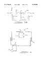
- FIG. 1is a schematic representation of a preferred embodiment of the automotive refrigerant circuit
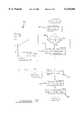
- FIG. 2is a cross-sectional view of the flow management center shown in FIG. 1;
- FIGS. 3a and 3bpresent cross-sectional views of flow management devices embodying the present invention
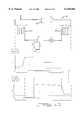
- FIG. 4is a schematic representation of an alternative automotive refrigerant circuit
- FIG. 5is a block diagram illustration of the control circuit interconnection to a reversible HVAC refrigerant circuit
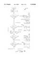
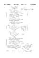
- FIG. 6is a flow diagram showing an overview of the control program for the preferred embodiment of the invention.
- FIG. 7is a flow diagram illustration of the expansion valve control program for the preferred embodiment of the invention.
- FIG. 8is a flow diagram of the compressor speed control module for the preferred embodiment of the invention.
- FIG. 9is a diagram illustrating the interaction between the expansion valve and compressor during the turn-on transition.
- FIG. 10is a datagram illustrating the relationship between the temperature cycle and a schematic representation of an HVAC system
- FIG. 11is a flow diagram of the anti-fog algorithm for the preferred embodiment of the invention.
- FIG. 12is a flow diagram of the heating mode selection module for the preferred embodiment of the invention.
- FIG. 13is a flow diagram of the air-handling method for the preferred embodiment of the invention.
- FIG. 14is a schematic representation of a preferred embodiment of an HVAC system coupled to a battery pack module
- FIG. 15is datagram illustrating the relationship between a preferred embodiment of the HVAC system and its heat load cycle.
- FIG. 16is a datagram illustrating the relationship between the temperature lever position and the corresponding operating mode.
- FIG. 1illustrates an exemplary reversible HVAC system 50 for motor vehicles that includes an air-flow structure 52, a refrigerant flow system 54, and a front panel 55 for providing controlling inputs.
- the reversible HVAC system 50can both heat and cool the passenger compartment air of a motor vehicle by using the refrigerant flow system 54 in conjunction with the air-flow structure 52 to transfer heat energy between the outside environment and the passenger compartment.
- heat energyis transferred from the outside environment to air that flows into the passenger compartment
- cooling modeheat energy is transferred to the outside environment from air that flows into the passenger compartment.
- the refrigerant flow system 54acts as a storage medium for heat energy that is being transferred between the outside environment and the passenger compartment.
- the air-flow structure 52controls the flow of conditioned air into the passenger compartment.
- An inside heat exchanger 88provides an interface between the refrigerant flow system 54 and the air-flow structure permitting the transfer of heat energy between the refrigerant and the air flowing into the passenger compartment.
- the front panel 55provides a means for the passengers to control the temperature, flow rate, and operating mode of the HVAC system.
- the air-flow structure 52includes a duct 56 through which air is supplied into the passenger compartment, a blower 58 for introducing air into the duct 56, a recirculation door 60 for controlling the proportion of fresh air to recirculated air, a PTC heater 62 for heating the air, a blend door 60 for controlling the proportion of air that flows over the PTC heater 62, and a set of duct outlets for discharging air into the passenger compartment.
- the duct outletsinclude a defrost outlet 64 for directing air towards the windshield of the vehicle, a panel outlet 66 for directing air towards the upper extremities of the passengers, and a floor outlet 68 for discharging air towards the lower extremities of the passengers.
- the duct outlets 64-68are selectively opened and closed by a mode damper 70 which operates in accordance with the position of the mode selector switch 72 located on front panel 55.
- the refrigerant flow system 54is operable in a heating mode and a cooling mode and includes a compressor 76, a four-way switch 78 for controlling the direction of refrigerant flow, an inside heat exchanger 88 for transferring energy between the refrigerant and air flowing into the passenger compartment, an outside heat exchanger 80 for interfacing with the outside environment, a flow management center 82 for reducing the pressure of refrigerant flowing into a heat exchanger that is functioning as an evaporator, shut-off valves 84 and 86 for system protection, zone-control heat exchanger 92 for providing independently controlled cooling to a local region, and pressure reducing device 90 for reducing the pressure of refrigerant flowing into the zone-control heat exchanger 92.
- the refrigerant flow system 54interacts with the air-flow structure 52 and the passenger compartment through the operation of the inside heat exchanger 88 during the heating and cooling modes.
- the function of the inside heat exchanger 88changes in each operating mode; during heating mode the inside heat exchanger 88 functions as a condenser transferring heat energy to air that passes through air-flow structure 52 into the passenger compartment and during cooling mode the inside heat exchanger 88 functions as an evaporator absorbing heat energy from the air that passes through air-flow structure 52 into the passenger compartment.
- the compressor 76is driven by a variable speed electric motor (not shown). Varying the speed of the electric motor causes a commensurate change in the suction pressure and refrigerant discharge capacity of compressor 76.
- the compressor in the present embodimentis a variable speed compressor, it is within the scope of the invention to employ a single speed compressor.
- the four-way switch 78is connected between the compressor 76 and the heat exchangers 80 and 88 to provide a method of changing from air conditioning mode to heat pump mode by reversing the direction of refrigerant flow.
- the inside heat exchanger 88functions as an evaporator during a cooling operation and as a condenser during a heating operation.
- Inside heat exchanger 88is arranged within duct 56 so that the air blown through the exchanger 88 is conditioned prior to passing over PTC heater 62 and being discharged through the duct outlets.
- Shut-off valve 84provides a means of interrupting refrigerant flow during HVAC operating modes that do not require operation of inside heat exchanger 88. Examples of such operating modes include disabling operation of the inside heat exchanger 88 as an evaporator at low ambient temperatures that could result in freezing of the heat exchanger 88 due to condensation, and modes where only secondary heat exchangers are operational such as zone control heat exchanger 92. Such operating modes include cooling of a battery assembly and cooling of pre-selected regions within the vehicle.
- the flow management center 82reduces the pressure of and expands the refrigerant to be supplied to the inside heat exchanger 88 during a cooling operation.
- the outside heat exchanger 80which is generally located towards the front of the vehicle, exchanges heat between the outside air and the refrigerant.
- a fan 94ensures a constant supply of outside air flows through outside heat exchanger 80.
- the outside heat exchanger 80functions as a condenser providing a means for the refrigerant to shed heat to the outside air.
- the outside heat exchanger 80functions as an evaporator absorbing heat energy from the outside air into the refrigerant.
- the flow management center 82provides a centrallized device for reducing the pressure of refrigerant flowing into a heat exchanger 80 or 88 functioning as an evaporator and acts as a source of high pressure liquid refrigerant for secondary heat exchangers.
- Conventional circuitsuse a separate pressure reducing device with bypass plumbing for each heat exchanger that functions as an evaporator.
- a receiver/drier functionis integrated into the flow management center 82 for eliminating contaminants and providing a reservoir of pressurized liquid refrigerant. Refrigerant tapped from the receiver portion is routed to pressure reducing device 90 and then to zone-control heat exchanger 92.
- the flow management center in the preferred embodimentincludes a receiver/drier function the principles of the invention can be extended to flow management devices that do not include a receiver/drier function.
- Flow management center 82is illustrated in greater detail in FIG. 2 to include a housing 100 defining bi-directional ports 102 and 104, a pressure sensitive valve 106, check valves 108 and 110, desiccant 112, a uni-directional flow member 114, pressure reducing valve 116, outlets 118 and 120, temperature probe 124, and pressure probe 122.
- Pressurized liquid refrigerantflows into bi-directional port 102 or 104, through the corresponding check valve 108 or 110, through the dessicant 112, into reservoir 113, up the uni-directional flow member 114, through pressure reducing device 116 and pressure sensitive valve 106, and finally reduced pressure refrigerant flows out of the other bi-directional port 104 or 102.
- the direction of refrigerant flowreverses as high pressure refrigerant flows into the bi-directional port that pressure reduced refrigerant was flowing from.
- the refrigerantthen flows through the corresponding check valve 110 or 108, through the dessicant 112, into reservoir 113, up the uni-directional flow member 114, through pressure reducing device 116 and pressure sensitive valve 106, and finally reduced pressure refrigerant flows out of the other bi-directional port 102 or 104.
- the pressure sensitive valve 106permits the flow of pressure reduced refrigerant out of one bi-directional port while preventing high pressure refrigerant from flowing directly between the bi-directional ports.
- the pressure sensitive valve 106closes the flow path from the port to the pressure reducing device 116 and opens a path from the pressure reducing device to the other bi-directional port 104 and 102. Closing the flow path from the bi-directional port 102 or 104 to the pressure reducing device forces refrigerant to flow through the corresponding check valve 108 or 110, through the dessicant 112, and into reservoir 113.
- the opposing check valve 110 or 108prevents high pressure liquid refrigerant in reservoir 113 from flowing out the opposing bi-directional port 104 or 102. Impurities within the refrigerant are removed by dessicant 112.
- Reservoir 113provides a pool of high pressure liquid refrigerant that can be sourced to multiple pressure reducing devices such as device 116 within the flow management center 82 as well as pressure reducing devices that provide reduced pressure refrigerant to secondary heat exchangers.
- Outlets 118 and 120provide a means of tapping off refrigerant from reservoir 113 and directing it to secondary heat exchanger circuits.
- the pressure sensitive valve 106is a dual poppet valve, however it is envisioned that other valves such as multiple check valves, mushroom valves, reed valves, or rotary valves may be employed. Additionally, similar valves as listed above can replace check valves 108 and 110.
- the pressure reducing device 116 in the preferred embodimentis an electronically controlled expansion valve it is within the scope of the invention to use mechanically controlled expansion valves as well as 90° valves.
- the desiccant 112 and the temperature and pressure probes 122 and 124are merely exemplary of additional functions that can be added to the flow management center, they are not required to practice the invention.
- the zone-control heat exchanger 92located within the interior of the vehicle provides cooling functions for local zones or assemblies.
- Examples of local zone coolinginclude battery assembly cooling, air conditioned seats, and individualized cooling of one side of the passenger compartment.
- Pressure reducing device 90reduces the pressure of and expands the refrigerant to be supplied to zone control heat exchanger 92.
- the expanded refrigerantabsorbs heat from the air or liquid which is passed through heat exchanger 92, thereby cooling the air or liquid.
- the front panel 55includes selector switches for setting the operating parameters of the air conditioning circuit 50.
- the switchesinclude a blower speed selector 73 that in the preferred embodiment is adjustable from 30% to 100% of the maximum blower speed, a mode selector switch 72 having five mode settings, a recirculation selector 75 for selecting fresh or recirculated air, and a sliding temperature lever 74 for setting the temperature of air discharged from the duct outlets.
- a mode selector switch in the preferred embodimenthas five discrete settings, the principles of the invention can be extended to a mode selector having an unlimited number of settings.
- the refrigerant discharged from the compressor 76flows through four-way switch 78 into outside heat exchanger 80 which functions as a condenser. As heat energy stored in the refrigerant is shed to the outside air which is blown through the exchanger 80 the refrigerant condenses to a high pressure liquid.
- the liquid refrigerantflows into a bi-directional port 102 of the flow management center 82, through the desiccant 112, into the reservoir 113, up the uni-directional flow member 114, through the pressure reducing valve 116, and then out the other bi-directional port 104.
- a portion of the refrigerantis tapped off from the reservoir 113 and directed towards a secondary loop as shown in FIG. 1 will be explained in a later paragraph.
- the refrigerant flowing through the pressure reducing valve 116is pressure reduced and then passes through the other bi-directional port 104.
- the pressure reduced refrigerantflows into the inside heat exchanger 88 which functions as an evaporator. Heat energy from air passing through inside heat exchanger 88 is absorbed by the pressure reduced refrigerant causing the refrigerant to change to the vapor state.
- the vapor state refrigerantflows from the heat exchanger 88 through the four-way switch 78 and back to the inlet of compressor 76 which compresses the vapor and directs it through four-way switch 78 to outside heat exchanger 80.
- the operation of the secondary loop during cooling modeis as follows.
- the portion of refrigerant that flowed from an outlet in reservoir 113flows through shut-off valve 86 into pressure reducing device 90.
- Pressure reduced refrigerantflows out of device 90 into local-zone heat exchanger 92 which functions as an evaporator.
- the refrigerantabsorbs heat from the air which passes through it thereby providing separately controlled cooling for a portion of the passenger compartment.
- the zone control heat exchanger 92 in the preferred embodimentfunctions as an air-to-refrigerant evaporator, it is within the scope of the invention to employ other heat exchangers such as refrigerant-to-refrigerant, water-to-refrigerant, and oil-to-refrigerant heat exchangers.
- the direction of refrigerant flowis reversed by changing the orientation of four-way switch 78.
- the refrigerant discharged from the compressor 76flows through four-way switch 78 into inside heat exchanger 88 which functions as a condenser. As heat energy stored in the refrigerant is shed to the inside air which is blown through the exchanger 88 the refrigerant condenses to a high pressure liquid.
- the liquid refrigerantflows into the bi-directional port 104 of the flow management center 82, through the desiccant 112, into the reservoir 113, up the uni-directional flow member 114, through the pressure reducing valve 116, and then out the other bi-directional port 102.
- the refrigerant flowing through the pressure reducing valve 116is pressure reduced and then passes through bi-directional port 102.
- the pressure reduced refrigerantflows into the outside heat exchanger 80 which functions as an evaporator. Heat energy from air passing through outside heat exchanger 80 is absorbed by the pressure reduced refrigerant causing the refrigerant to change to the vapor state.
- the vapor state refrigerantflows from the heat exchanger 80 through the four-way switch 78 and back to the inlet of compressor 76 which compresses the vapor and directs it back through four-way switch 78 to inside heat exchanger 88.
- the secondary loopoperates in the same manner as during a cooling mode.
- Refrigerant from outlet 118 of flow management center 82flows through pressure reducing device 90 and into local-zone heat exchanger 92 in which it absorbs heat from air that is passing through the exchanger 92.
- Pressure reducing device 90 pressurereduces the refrigerant to increase its capacity to absorb heat energy from air or fluid flowing through the heat exchanger 92.
- a common sense point at the outlet of pressure reducing device 116is provided for pressure reduced (low-side) refrigerant. Sensing temperature and pressure at the flow management center eliminates the need of conventional systems for sensing at the inlet to each heat exchanger.
- an alternate flow management device 81which does not include the receiver/drier function, but provides reversibility with simpler plumbing than conventional systems and a single pressure reducing device.
- the flow management deviceincludes a housing 100 defining bi-directional ports 102 and 104, a pressure sensitive valve 106, check valves 108 and 110, a uni-directional flow member 114, temperature probe 122, and pressure probe 124.
- the flow management device 81includes all the capabilities of the flow management center 82 with the exception of the receiver/drier function.
- FIG. 4illustrates another embodiment of an automotive air conditioning circuit 40 that includes a compressor 41, an outside heat exchanger 42, an inside heat exchanger 43, two four-way switches 44 and 45, a receiver/drier 46, and an electronic expansion valve 47.
- Four-way switch 45, receiver/drier 46, and expansion valve 47functionally replace the flow management center 82 that is employed in circuit 50 (see FIG. 1).
- the function of four-way valve 45is the mirror image of the function of four-way valve 44.
- Valve 44is employed to reverse the flow of refrigerant through the heat exchangers 42 and 43. It essentially converts uni-directional refrigerant flow from the compressor 41 into bi-directional refrigerant flow into the heat exchangers 42 and 43.
- four-way valve 45converts bi-directional refrigerant flow from the heat exchangers 42 and 43 into a uni-directional flow through receiver/drier 46 and expansion valve 47.
- Receiver/drier 46removes contaminants from the refrigerant and ensures a continuous flow of high pressure liquid refrigerant into expansion valve 47.
- Expansion valve 47provides refrigerant pressure reduction and expansion for heat exchangers 42 and 43.
- Expansion valve 47is preferably an electronic expansion valve that receives its controlling inputs from a controller that monitors the saturation and superheat temperature of the heat exchangers 42 and 43.
- other pressure reducing devicessuch as block valves, 90° valves, and thermal expansion valves (TXV) are within the scope of the invention.
- TXVthermal expansion valves
- outside heat exchanger 42functions as a condenser shedding heat to the outside environment and inside heat exchanger 43 functions as an evaporator absorbing heat from air that is blown into the passenger compartment.
- the refrigerant cycleis as follows: refrigerant flows out of compressor 41, through four-way valve 44, into the outside heat exchanger 42, through four-way valve 45, into receiver/drier 46 and expansion valve 47, through four-way valve 45, to inside heat exchanger 43, through four-way valve 44, and back to compressor 41.
- four-way valve 44changes orientation causing the flow of refrigerant to heat exchangers 42 and 43 to reverse. With the reversal in the direction of refrigerant flow the functions of the heat exchangers 42 and 43 reverse as inside heat exchanger 43 functions as a condenser and outside heat exchanger 42 functions as an evaporator.
- the orientation of four-way valve 45is also changed to ensure that the direction of refrigerant flowing into receiver/drier 46 and expansion valve 47 remains constant.
- the refrigerant cycle during heat pump modeis as follows: refrigerant flows out of compressor 41, through four-way valve 44, into the inside heat exchanger 43, through four-way valve 45, into receiver/drier 46 and expansion valve 47, through four-way valve 45, to outside heat exchanger 42, through four-way valve 44, and back to compressor 41.
- the inventionprovides a flow management device with bi-directional ports in which refrigerant flowing into either port passes through an expansion valve and exits the other port. Additionally, the invention can integrate the receiver/drier function into a flow management device with bi-directional ports to provide the capability of tapping off refrigerant flow for secondary cooling circuits. Also, the present invention decreases the complexity of automotive HVAC systems by integrating a flow management device into the system to reduce the number of valves required to implement a reversible heating and cooling HVAC system. A further capability of the invention is to provide a centralized flow management center with taps for refrigerant to reduce the complexity of automotive HVAC systems that implement multi-zone control.
- FIG. 5illustrates the control system configuration to implement the preferred embodiment of the HVAC circuit 50.
- the outside coil 80, flow management center 82, inside heat exchanger 88, four-way switch 78, compressor 76, duct 56, and front panel 55are interconnected in a manner similar to circuit 50 illustrated in FIG. 1.
- controller 130which controls the compressor speed and flow management center 82 operation based upon inputs from front panel 55, duct 56, and the refrigerant system 54.
- the passengerselects a passenger compartment temperature and operating mode by setting the switches of front panel 55.
- the front panel 55 switch settingsare decoded by the controller 130, which converts the settings to values that represent desired temperature, operating mode, and blower speed.
- the controller 130also monitors sensors that measure the actual ambient and passenger compartment temperature as well as refrigerant temperature and pressure.
- the controller 130compares the decoded settings to the actual ambient and passenger compartment temperature, and generates signals that modify the operation of the refrigerant flow system 54 and air-flow structure 52 to bring the actual passenger compartment temperature in conformance with the desired temperature as represented by the front panel 55 switch settings.
- the operation of the refrigerant flow system 54is modified by controller 130 through output signals that control the orientation of the four-way switch 78, the speed of compressor 76 and the duty cycle applied to the pressure reducing device 116 within the flow management center 82.
- Changing the orientation of four-way switch 78causes a reversal in the direction of refrigerant flow.
- the direction that refrigerant flowsdictates whether the HVAC system is in the heating mode or the cooling mode by interchanging the functions of the outside heat exchanger 80 and the inside heat exchanger 88. In heating mode the outside heat exchanger 80 functions as an evaporator and the inside heat exchanger 88 functions as a condenser 88.
- the outside heat exchanger 80functions as a condenser and the inside heat exchanger 88 functions as an evaporator.
- Varying the speed of compressor 76 during a cooling mode or a heating modecauses a change in the refrigerant temperature at the compressor 76 inlet and outlet, which has a direct effect on the temperature of air blown into the passenger compartment.
- Changing the duty cycle applied to the pressure reducing device 116 during either cooling or heating modecauses a variation in the quantity of refrigerant that the pressure reducing device 116 permits to flow into the heat exchanger 80 or 88 that is functioning as an evaporator. Too much refrigerant flowing through the evaporator leads to flooding the compressor 76, causing degraded compressor 76 performance.
- the controller 130constantly adjusts the duty cycle applied to the pressure reducing device to keep the evaporator operating at maximum efficiency and adjusts the speed of compressor 76 to control the temperature of the air blown into the passenger compartment.
- the air-flow structure 52 operationis modified by changing the position of blend door 61 and the position of recirculation door 60.
- Changing the position of blend door 61changes the amount of supplemental electric heating that is applied to the air flowing through the air-flow structure 52, directly effecting the temperature of the passenger compartment.
- the position of recirculation door 60controls whether fresh air from the outside or recirculated air from inside is directed into the passenger compartment. Typically, more energy is required to heat or cool fresh air than recirculated air because of the greater differential between the temperature of the air flowing into the HVAC system 50 and the desired passenger compartment temperature.
- Inputs to controller 130 from the front panel 55include blower speed from blower speed selector 73, mode selection from mode selector switch 72, and the target temperature from temperature lever 74.
- the duct 56 inputsinclude inlet and outlet temperatures from temperature probes 132, 133, and 134.
- Inputs from the refrigerant system 54 to the controller 130include temperature probe 135 for sensing ambient temperature, temperature probe 124 for sensing the expansion valve 116 outlet temperature, temperature probe 136 for sensing superheat temperature, and pressure probe 138 for sensing suction pressure.
- Controller 130is preferably a microprocessor-based controller, that includes a processor 140 and associated memory 142.
- An analog-to-digital converter (A/D) 144converts signals from the various sensors to a digital form used by processor 140.
- a driver circuit 146operates the flow management center 82 and compressor 76. This may be for example an interface circuit that connects to the electric motor for driving the compressor 76 in response to system temperature inputs. The interface circuit may also provide a duty cycle signal for controlling the expansion valve 116 to maintain a regulated average superheat temperature in the compressor suction line. Additionally, the driver 146 may include an interface circuit coupled to four-way switch 78 for reversing the switch from cooling mode to heating mode.
- Processor 140includes a main program 151, depicted in the flowchart of FIG. 6, to control the operating mode selection, compressor speed control, and electronic expansion valve (EXV) control.
- FIG. 6gives an overview of the control strategy illustrating the major functional modules that are involved.
- the main program 151provides the timing for execution of the various control modules.
- the programenters the operating mode selection module in which the operating mode of the system is selected.
- the supported operating modesinclude defrost mode, vent mode, PTC heater mode, heat pump mode, and air conditioning mode.
- the inputs monitored by the controller 130 to select the HVAC system 50 operating modeinclude the position of mode selector switch 72, temperature lever 74, inlet temperature, and during a heating operation the capacity of heat pump mode.
- the preferred embodimenthas five discrete operating modes, the principles of the invention can be extended to systems having either fewer operating modes or a continuously variable set of operating modes.
- FIG. 16illustrates the system operating modes.
- controller 130turns on the PTC heater 62 and moves the blend door to a position determined by the location of temperature lever 74. However, for the first 3% of temperature lever 74 travel from the full cold position the controller turns off PTC heater 62 and only enables the vents.
- controller 130In the heating mode, with ambient temperatures greater than 40° F. or defrost operation with ambient temperatures between 40° F. and 60° F., controller 130 turns on the heat pump and if necessary the PTC heater with blend door to generate the desired temperature that is reflected by the position of temperature lever 74. For the first 3% of temperature lever 74 travel from full cold the controller 130 turns off the heat pump and PTC heater 62 and only enables the vents. At temperatures greater than 100° F. the controller 130 turns off PTC heater 62.
- the third operating modeis selectable for ambient temperatures that are greater than 40° F. Cooling mode is also used for defrost when the ambient temperature is greater than 60° F.
- Cooling modeis also used for defrost when the ambient temperature is greater than 60° F.
- the controller 130varies the compressor suction pressure set point from 20 to 45 psig as the temperature lever 74 is moved from cold to warm. Varying the suction pressure set point causes a direct change in the compressor speed, thereby causing the air temperature at the duct outlets to change. From 33% to 100% of temperature lever travel the controller 130 sets the compressor 76 suction pressure to a constant 30 psig and turns on the PTC heater 62 to reheat the conditioned air.
- the programenters the recirculation door positioning module which is described below with reference to FIG. 13.
- the recirculation door positioning modulecontrols the proportion of fresh air to recirculated air that is blown into the passenger compartment.
- the programenters modules for monitoring and disabling the compressor in response to detected faults.
- the compressor speed control modulewhich is described below with reference to FIG. 8, is entered at step 160. Varying the speed of compressor 76 causes a proportional change in the air temperature blown from the duct outlets 64-68.
- Step 162leads to the EXV control module which is described with reference to FIG. 7.
- the EXV control module 162modulates the output of the expansion valve 116 in response to changes in the vapor temperature sensed at the compressor 76 and the compressor suction pressure.
- FIG. 7illustrates the detailed operation of EXV control module 162.
- the module 162controls the volume of refrigerant that is pressure reduced by the expansion valve 116 to maintain a relatively constant superheat temperature at the outlet of the evaporator.
- To reduce the outlet temperature of the refrigerantthe volume of refrigerant flowing into the evaporator is increased, thereby increasing the heat load capacity of the refrigerant.
- step 164the proportional-integral-differential (PID) constants are chosen based upon whether the system is in heating mode or cooling mode.
- PIDproportional-integral-differential
- the selection of PID constantsis based upon the particular system characteristics and is well known in the art.
- the EXV control moduleproceeds to steps 166 and 168 wherein the expansion valve duty cycle is initialized based upon ambient temperature and operating mode when the system first enters either heat pump mode or air conditioning mode.
- the graph appended to step 168depicts the selection criteria for the duty cycle.
- Ambient temperatureis sensed by temperature probe 135 located in front of the outside heat exchanger 80.
- the initial duty cycleis then set to a value ranging from 50% to 100% of the maximum EXV duty cycle depending on the ambient temperature.
- the systemtransitions through a start-up period before settling into steady-state operation.
- the duty cycle of the EXVis varied in order to maintain a constant superheat temperature, 4° F. greater than the saturation temperature, at the inlet to compressor 76.
- the average superheat temperatureis calculated by measuring the vapor temperature of refrigerant exiting the evaporator and subtracting the saturation temperature of the fluid.
- the saturation temperatureis obtained by measuring the compressor inlet suction pressure and using the saturation temperature that corresponds to the suction pressure.
- the outlet of the expansion valve 116 located in the flow management centerprovides a common temperature measurement location for evaporator inlet temperature in either heating mode or cooling mode.
- temperature probesare required at the inlets to both the inside and outside heat exchangers to provide inlet temperature in both operating modes.
- the updated superheat temperature from step 170is used at step 172 to calculate a revised setting for the EXV duty cycle.
- the controller 130limits the value of the EXV duty cycle to between 5% and 100% to ensure the device remains within a known operating region.
- the compressor speed control module 160is illustrated.
- the compressor speedis controlled by applying a variable duty cycle to the electric motor that drives the compressor 76.
- the duty cycleis varied in response to a controlling input such as temperature lever position and compressor suction pressure. Varying the speed of compressor 76 causes a proportionate variation in the discharge temperature and discharge pressure of refrigerant flowing out of the compressor 76 as well as an inversely proportional change in the compressor suction pressure and refrigerant suction temperature.
- the increased refrigerant discharge temperatureresults in an increased condenser temperature, increasing the capacity of the HVAC system 50 to provide heat during heating mode.
- the decreased refrigerant suction temperatureresults in a decreased evaporator temperature, increasing the capacity of the HVAC system 50 provide cooling during cooling mode.
- the speed of the compressor 76is therefore varied to maintain air blown into the passenger compartment at a relatively constant temperature during both heating mode and cooling mode.
- the desired temperatureis set by adjusting the temperature lever 74 on front panel 55.
- the controller 130calculates the target suction pressure corresponding to the temperature lever position (x/L) which is equal to 20+75*(x/L) for a lever travel distance equal to 33% of the available distance. Using the suction pressure as the controlled parameter instead of air temperature provides a more stable and faster responding system.
- the duty cycle of pressure reducing valve 116is changed by controller 130, causing a shift in the flow of refrigerant, resulting in a slight variation of the compressor suction pressure.
- the controller 130modifies the speed of compressor 76 to bring it in conformance with the target suction pressure.
- the required change in the speed of the compressor 76is significantly less than the change that would be required in an HVAC system that uses compressor speed alone to compensate for changes in outlet temperature.
- the minor change in compressor speedis imperceptible to the passengers, leading to enhanced driving comfort.
- HVAC system 50In addition to eliminating surging, the response time of HVAC system 50 is reduced by using suction pressure as the controlled input. Cooling air at the desired temperature is blown over passengers in significantly less time than conventional systems that control air temperature directly. As a result, unlike conventional systems, PTC heating of the cooled air is not required to provide fine control over the air temperature, resulting in more energy efficient vehicle operation.
- the compressor speedis varied in reaction to changes in the temperature of the air flowing out of the inside heat exchanger 88.
- suction pressureis not directly related to the temperature of air flowing out of the inside heat exchanger. Therefore the air temperature sensed by temperature probe 133 is used as the controlling input for compressor speed.
- step 176the controller 130 calculates the error and error derivative to be used in the PID controller for the controlled input.
- the controlled inputIn air conditioning mode the controlled input is the suction pressure and in heat pump mode the controlled input is the post inside heat exchanger air temperature measured by temperature probe 133.
- step 178the PID constants corresponding to the appropriate operating mode are selected.
- step 180the PID controller calculates the change in compressor duty cycle based on the PID constants and the calculated error and error derivative. The revised duty cycle is limited to between 5% and 90% to ensure the compressor 76 is operated within specified parameters.
- FIG. 9illustrates the interaction between the EXV control loop and the compressor speed control loop during the cooling mode start-up transition.
- the EXV control loopregulates the volume of refrigerant that flows through pressure reducing device 116 maintaining a predetermined refrigerant superheat temperature at the outlet of the evaporator.
- a secondary effect of the EXV operationis that as the EXV permits an increased volume of refrigerant to flow, the suction pressure at the inlet to compressor 76 decreases.
- the operation of the compressor 76has a corresponding interaction with the EXV.
- the speed of compressor 76is changed, the resulting change in suction pressure and temperature at the inlet to compressor 76 causes a change in the saturation temperature of refrigerant that flows through the evaporator.
- Increased compressor 76 speedcauses a lower suction pressure, leading to a lower saturation temperature, resulting in the refrigerant temperature rising to the predetermined superheat temperature earlier in the traverse of the evaporator.
- the EXV loopcompensates for the change in superheat temperature by permitting an increased volume of refrigerant to flow through the evaporator, thereby causing a higher suction pressure.
- the EXVis set to an initial duty cycle of 50% at step 168 (see FIG. 7).
- the compressor suction pressureis set to achieve the target suction pressure corresponding to the location of temperature lever 74. Initially, the compressor suction pressure decreases slightly during the first seconds of operation as fluid pours through the EXV, then as the compressor spins up towards steady-state speed suction pressure begins to increase significantly.
- the EXV duty cycleincreases until the suction pressure has increased to a point where the EXV begins to track the suction pressure.
- the compressorDuring the early stages of start-up it is not unusual for the compressor to flood until the compressor speed increases a sufficient amount to develop appropriate suction pressure.
- the compressoris operated on the borderline of flooding during the start-up transition thereby contributing to a faster system response time. Also, as the EXV duty cycle begins to track the suction pressure it will overshoot its steady-state value by a slight amount. The underdamped response displayed by the EXV control loop results in a further reduction in the system response time. In combination the improvements result in air cooled to the desired temperature blowing over the faces of passengers within approximately 35 seconds of system start-up.
- the inventionprovides a system for improving the steady-state response time of an automotive HVAC system. Additionally, the invention permits a reduction in the start-up time of an automotive air conditioning system. Also, the invention provides a system for controlling an HVAC system that employs a flow management device. The invention further provides a system for controlling an HVAC system incorporating a centralized flow management center.
- a single loop reversible air conditioning and heat pump system 191is illustrated with the corresponding temperature cycle diagrams for air conditioning mode 190 and heat pump mode 192.
- the preferred embodiment of the present inventionprevents undesirable fogging by slowly increasing the speed of compressor 76 over a predetermined period of time.
- foggingmay occur during the transition from cooling mode to heating mode.
- FIG. 10Prior to describing the solution provided by the presently preferred embodiment, a brief description of the refrigeration cycle and how fogging occurs in a reversible system is provided with reference to FIG. 10.
- the refrigeration cycleessentially uses a small amount of energy to power a compressor in order to transfer a greater amount of heat energy from one environmental region to another environmental region. It does this by using the cooling effect of evaporation to lower the temperature of the air passing through one heat exchanger (the evaporator) 88 and using the heating effect of condensing high temperature, high pressure gas to raise the temperature of the air passing through another heat exchanger (the condenser) 80.
- the condenser 80With reference to waveform t 1 of FIG. 10, drawn from right to left, the temperature profile of refrigerant flowing from an evaporator 88, through a compressor 76 and four-way switch 78, and then through a condenser 80 is illustrated.
- Refrigerant entering the evaporator 88is at low pressure and low temperature.
- the temperaturebeing the saturation temperature of the pressure reduced refrigerant.
- the air that exits the evaporator 88is noticeably cooled due to the transfer of heat energy from the air to the refrigerant.
- the cooler airno longer has the capacity to retain the same amount of moisture as the warmer air that was blown into the evaporator 88, therefore the excess moisture condenses out of the air onto the external surface of the evaporator 88.
- the vapor state refrigerantflows from the evaporator 88 to the compressor 76 where it is compressed to a high pressure, high temperature vapor before flowing into the condenser 80.
- any further heat energy that is absorbed in the refrigerantcauses the refrigerant temperature to increase beyond the saturation temperature into a superheated temperature range.
- the superheated refrigerantflows to the compressor 76 which compresses it to a high pressure, high temperature vapor which is directed to the inside heat exchanger (the condenser) 88.
- the condenser 88As the high temperature vapor flows into the condenser 88, the temperature of the condenser 88 rapidly rises to an equivalent temperature.
- Moisture that had accumulated on the inside coil 88 during the air conditioning modebegins to boil off as the condenser 88 increases in temperature.
- the moistureis absorbed by air flowing through condenser 88 into the passenger compartment. Fogging then occurs when the moisture laden air strikes the cold inside surface of the passenger compartment windows.
- FIGS. 5 and 11illustrate an exemplary anti-fogging system for controlling the operation of a reversible HVAC system 50 for automobiles.
- FIG. 5as explained earlier in this specification illustrates a control system for an automotive HVAC system.
- controller 130minimizes the effects of fogging by gradually increasing the compressor speed at a predetermined rate and regulating the flow management center operation to ensure efficient use of the evaporator.
- a flow management center 82is employed in the preferred embodiment it is within the scope of the invention to use a pressure reducing device with a separate receiver/drier. Additionally, the invention encompasses any variable speed or capacity compressor, even though the compressor in the preferred embodiment is an electric compressor.
- Processor 140is programmed to control the compressor speed and flow management center operation as depicted in the flowchart of FIG. 11.
- FIG. 11provides a general overview of the main system operating modes and the detailed program steps related to the anti-fogging routine.
- the steps that are included in the anti-fogging routine 201are spread throughout a number of program modules such as the operating mode selection 152, compressor speed control 160, and EXV control 162 (see FIG. 6). Calculated changes to the outputs that control the speed of compressor 76 and the regulation of pressure reducing device 116 only occur within the designated modules. To clarify the included steps, they have been brought together and listed in anti-fog routine 201.
- the programenters air conditioning mode in which cooling air is blown into the passenger compartment.
- air conditioning modeas a byproduct of the refrigeration process moisture accumulates on the external surface of inside heat exchanger 88.
- an anti-fog flagis set to provide an indication that there is moisture on the surface of the inside heat exchanger 88. The anti-fog flag will remain set until heat pump mode is entered at step 204.
- the programcontinues into the anti-fog sequence 208 if the anti-fog flag is set, otherwise it branches off to steady-state heat pump mode at step 210.
- the anti-fog sequencebegins with selecting a post-inside heat exchanger air target temperature and a duration of operation at step 212 from a table of values that are represented in the graph.
- the actual post-inside heat exchanger air temperatureis measured by probe 133.
- the target temperatureis set equal to the ambient plus an offset that is increased over time. Limiting the post-inside heat exchanger target temperature to a specified offset above ambient indirectly limits the temperature of the compressed refrigerant vapor that flows into the condenser 88.
- the evaporation rate of moisture located on the inside heat exchanger 88is directly related to the refrigerant temperature at the inlet to condenser 88.
- gradually increasing the target temperaturecauses a gradual increase in the compressor speed, which causes a gradual increase in the compressor discharge pressure, which results in a gradual increase in the refrigerant temperature at the inlet to the condenser, thereby limiting the evaporation rate of moisture on the condenser 88.
- the compressor target suction pressureis set to 45 psi. Starting the suction pressure at 45 psi ensures that the starting discharge pressure and temperature are low enough to prevent uncontrolled moisture evaporation from the condenser 88.
- the suction pressureis related directly to the speed of compressor 76.
- a PID controllercalculates the new compressor speed setting based upon the target temperature and previous suction pressure.
- the change in suction pressure from the previous settingis limited to prevent undesirable changes in compressor speed which could lead to high discharge temperatures and uncontrolled condenser moisture evaporation.
- the preferred embodiment of the inventioncontrols the compressor speed to regulate the moisture evaporation rate, it is within the scope of the invention to control other system parameters such as suction pressure, discharge pressure, or condenser inlet temperature.
- the PTC heater 62is turned on and the blend door 61 is set to a position that will enable the HVAC to achieve the temperature lever target temperature.
- the required door 61 positionis obtained from a lookup table that correlates blend door position to differential temperature and airflow.
- the recirculation door 60is set to the full fresh air position. Setting the recirculation door 60 to the full fresh air position in combination with slowly evaporating moisture from the condenser prevents fogging in the passenger compartment. As moisture is slowly evaporated off of the condenser it is absorbed by the fresh air flowing past the recirculation door 60, through inside heat exchanger 88, and into the passenger compartment. The moisture laden air flowing into the passenger compartment from the outside causes the internal air pressure to increase, acting to drive air out of the compartment through vents and other unsealed openings. Pushing air out the vents prevents an excessive amount of moisture laden air from accumulating in the passenger compartment as well as ensuring that the driest possible air is passed over the inside heat exchanger 88.
- controller 130has executed the table of values depicted graphically at step 212. Having completed the predetermined routine, all of the moisture that existed on inside heat exchanger 88 has evaporated and therefore the temperature of the refrigerant entering the condenser 88 no longer needs to be controlled.
- the anti-fog flagis reset and the heat pump system transitions to normal steady-state heat pump mode in which the speed of the compressor 76 is controlled such that a desired duct outlet temperature as selected with temperature lever 74 is attained.
- the inventionprovides a system which controls fogging when changing modes in a reversible HVAC system. Additionally, through the use of the anti-fogging method the rate of initial heating of the passenger compartment is not compromised. Additionally, the invention permits a system which controls fogging in an HVAC system when initially starting air conditioning mode.
- FIGS. 5 and 12illustrate an exemplary temperature control system for a reversible air conditioning and heat pump HVAC system for an electric automobile.
- FIG. 5illustrates the interconnection of controller 130 to an automotive air conditioning circuit 50.
- Controller 130controls the compressor speed, flow management center 82 operation, and blend door 61 positioning based upon inputs from front panel 55, duct 56, and the refrigerant system.
- the controller 130is preferably a microprocessor-based circuit, that includes processor 140 for executing a program, its associated memory 142, an A/D 144 for converting analog signals into digital inputs, and a driver circuit 146 for interfacing with system components.
- Processor 140is programmed to control the heating mode selection that is depicted in the flowcharts of FIGS. 12A and 12B.
- the heating mode selection programscontrol the operation of the HVAC circuit 50 during a heating operation.
- the steps that are included in the heating mode selection modulesare spread throughout a number of program modules such as the operating mode selection 152, compressor speed control 160, and EXV control 162 (see FIG. 6). Calculated changes to the outputs that control the speed of compressor 76 and the regulation of pressure reducing device 116 only occur within the designated modules. To clarify the included steps, they have been brought together and listed in the two heating mode selection modules.
- Heat to the passenger compartmentis provided by a combination of the HVAC in heat pump mode and PTC heaters 62 depending on the ambient temperature and the requested target temperature as selected by the position of the temperature lever 74.
- heatis supplied only by the PTC heater as the reversible HVAC refrigerant system is disabled to prevent icing of the heat exchangers 80 and 88 which would result in reduced airflow and odors in the passenger compartment.
- heatis supplied by either the heat pump, the PTC heater 62, or the heat pump supplemented by the PTC heater 62.
- a target temperatureis calculated based upon the position of temperature lever 74.
- a lookup tablecontains values that correlate temperature lever position to the target temperature of the air flowing from the duct outlets 64-68. The creation of a lookup table containing such values is well known in the art.
- the target temperatureis then compared to the temperature of air flowing into inside heat exchanger 88.
- the pre-indoor heat exchanger air temperatureis measured by probe 132. If the air temperature at probe 132 exceeds the target temperature the PTC heater 62 is turned off, the heat pump is turned off, and the blend door 61 is set to the max cool position. In the max cool position air bypasses the PTC heater and flows directly to the duct outlets. During this mode of operation the outside air which flows into the duct 56 is warmer than the passenger has requested via the temperature lever 74. To cool the incoming air to the desired temperature the passenger has the option of enabling air conditioning mode.
- the compressor speedis adjusted by a PID controller at step 276 to drive the temperature of post inside heat exchanger air to the target temperature.
- the refrigerant suction pressure and temperaturedecreases enabling the refrigerant to absorb a greater amount of heat from the external air as the refrigerant traverses the outside heat exchanger (evaporator) 80.
- the refrigerantis additionally compressed by the compressor to a greater discharge temperature and pressure prior to being routed to the inside heat exchanger (condenser) 88.
- the increased heat load of the refrigerant, obtained from the outside heat exchanger 80,is then transferred to the air flowing through the inside heat exchanger 88.
- the increased heat transfercauses a commensurate increase in the post inside heat exchanger air temperature, assuming the ambient temperature and air flow rate remains constant.
- the post inside heat exchanger air temperatureis measured by probe 133 and compared to the target temperature.
- the post inside heat exchanger air temperaturerepresents the air temperature prior to the PTC heater. If the air temperature is greater than the target temperature, then supplemental heat is not required to achieve the target temperature. Therefore, at step 280 the controller turns PTC heater 62 off, sets the blend door 61 to the max cool position, and returns to step 270 to begin another iteration. This is the normal operating loop during heat mode operation as the controller 130 regulates the air temperature to the selected target temperature.
- the post inside heat exchanger air temperaturewill exhibit normal closed loop operation by fluctuating slightly about the target temperature.
- the electric heater, PTC heater 62is turned on. As the air flow rate across the PTC heater 62 increases, the heat output of the device increases thereby transferring a greater amount of heat to the passenger compartment.
- blend door 61provides a path for a portion of the air to bypass the PTC heater 62 and recombine downstream with air that has flowed through the PTC heater 62. By reducing the quantity of air that flows over the PTC heater 62, less heat is transferred to the air, thereby reducing the commensurate increase in the temperature of the air, and providing a simple means of regulating the temperature of the recombined air.
- the required blend door position to achieve the target temperatureis calculated in a manner known in the art.
- the required effectivenessrepresents the amount of PTC heating that is required to raise the temperature of the post inside heat exchanger air to the target temperature at the existing airflow across the PTC.
- the controller 130sets the position of blend door 61 and the loop returns to step 270 to start another iteration. This is the normal operating loop when supplemental heat from the PTC heater 62 is required to raise the duct outlet air to the requested temperature.
- the position of the blend door 61is varied slightly as the controller 130 responds to changing conditions.
- the heating mode selection programcan be implemented as illustrated in FIG. 12B.
- the program illustrated in FIG. 12Bis particularly suitable for operating modes where the overhead energy that is expended turning on the heat pump or PTC heater 62 exceeds the energy required to raise the passenger compartment temperature to the desired temperature.
- a forty second timeris started. The timer sets the time period during which the heat pump attempts to attain the target temperature.
- the heat pump target temperatureis calculated based on the position of temperature lever 74.
- the compressor speed PID controlleris adjusted at step 304 to drive the compressor speed towards attaining the target temperature.
- the heat pump gainis calculated.
- the heat pump gainrepresents the work the heat pump contributes to raise the temperature of the passenger compartment under the existing operating conditions.
- the heat pump gainis set equal to the outlet temperature, probe 133, minus the inlet temperature, probe 132, divided by the outlet temperature.
- the post-inside heat exchanger air temperature as measured by probe 133is compared to the target temperature calculated at step 302 to determine if the heat pump is capable of attaining the target temperature. If the heat pump does attain the target temperature the forty second timer is reset at step 310 and the program returns to step 302. Additionally, if the heat pump has not attained the target temperature but the 40 second timer has not timed out, the program returns to step 302 to continue to attempt to attain the target temperature. However, if the heat pump does not attain the target temperature within 40 seconds then at step 314 the measured values for heat pump gain and ambient temperature are stored for later use.
- the heat pumpis allowed 40 seconds to attain the target temperature, it is within the scope of the invention that the allowed time may range from about 0 seconds to beyond 40 seconds.
- the heat pump heating capabilitymay be characterized by factory test or simulation and a number representative of the capability may be stored in memory for later recall to determine if the heat pump is capable of attaining a target temperature.
- the heating modetransitions from the heat pump to PTC heater 62 by gradually decreasing the heat pump output and increasing the PTC heater 62 over a 40 second period. Making a gradual transition enhances passenger comfort by reducing the noticeability of the change in system operation.
- the stored value for heat pump gainis adjusted for changes in ambient temperature.
- the revised value for heat pump gainis compared to the system gain that represents the amount of work required to heat the passenger compartment to the target temperature. If the system gain exceeds the heat pump gain, there is insufficient capacity in heat pump mode for heating the passenger compartment, therefore the program remains in PTC heat mode and returns to step 318. If the heat pump gain exceeds the system gain, the heat pump is capable of supplying the required heat necessary to attain the target temperature.
- the programadvances to step 322 and transitions from the PTC heater 62 to heat pump over a 40 second time period, finally returning to heat pump mode at step 300.
- the inventionprovides a system which minimizes energy consumption during a heating operation of an automotive HVAC system. Additionally, the method can be employed to dynamically update the heating mode selection as operating conditions change. Also, through the use of the method the energy efficiency of an electric vehicle is increased. Additionally, the invention provides an energy efficient method for controlling the passenger compartment temperature of an electric vehicle.
- FIG. 5illustrates the interconnection of controller 130 to an automotive air conditioning circuit 50.
- Controller 130controls the compressor speed, flow management center 82 operation, and recirculation door 60 positioning based upon inputs from front panel 55, duct 56, and the refrigerant system.
- Recirculation door 60may be set to any value from full fresh air, through part fresh air with part recirculated air, to full recirculated air.
- the recirculation door control program 251is illustrated in FIG. 13. Although FIG. 13 depicts all of the recirculation door program components existing in a single separate program module, it is within the scope of the invention for the different elements to be spread throughout the system program. In the preferred embodiment of the invention the steps that are included in the heating mode selection module are spread throughout a number of program modules such as the operating mode selection 152 and recirc. door positioning 154 modules (see FIG. 6). To clarify the included steps, they have been brought together and listed in the blend door control module.
- step 250is executed and the recirculation door 60 is set to the recirculation position.
- the recirculation door 60By starting in the recirculation position less energy is consumed controlling the temperature of the passenger compartment.
- air from within the passenger compartmentis routed through the inside heat exchanger 88 before being directed back into the passenger compartment. Therefore to raise the duct outlet air to the desired temperature the heat transferred from inside heat exchanger 88 only has to supplement the difference between the desired temperature and the temperature of the passenger compartment.
- fresh air modeto raise the duct outlet air to the desired temperature the heat transferred from inside heat exchanger 88 supplements the difference between the desired temperature and the temperature of the external air which is flowing into the passenger compartment.
- step 252the inputs from the front panel 55 are interrogated to determine if a particular positioning of the recirculation door has been requested. If a recirculation door position change has been requested, then at step 254 the recirculation door is set to the requested position at step 254.
- step 256the program optionally begins an anti-fog sequence.
- fogging of the passenger compartment windowsmay occur when the reversible HVAC system 50 switches from cooling mode to heating mode.
- moistureaccumulates on the external surface of the inside heat exchanger 88 which functions as an evaporator.
- the HVACswitches from cooling mode to heating mode the refrigerant flowing into the inside heat exchanger 88, which functions as a condenser, rapidly increases in temperature.
- the refrigerantbegins to raise the temperature of the condenser 88, moisture that had accumulated on the inside heat exchanger 88 during the cooling mode begins to boil off.
- the evaporating moistureis absorbed by air flowing through condenser 88 into the passenger compartment. Fogging then occurs when the moisture laden air strikes the colder windows of the passenger compartment.
- step 258the air handling procedure during an anti-fog sequence is performed.
- the front panel selection for the recirculation door 60 positionis overridden as the door 60 is set to the full fresh air position. With fresh air flowing into the passenger compartment the air pressure within the compartment increases, forcing air out of vents and door seal cracks. As new fresh air carrying its load of moisture is blown into the passenger compartment, pre-existing moisture laden air is forced out through the vents to the outside environment.
- the recirculation door 60remains in the fresh air position until the anti-fog sequence is completed, at which time the recirculation door is reset to its former position.
- step 260the program begins an air blow-by sequence.
- a predetermined valuesuch as approximately 42 mph
- the pressure from air flowing into the fresh air duct 59flows not only through the blower 58, but also back up through the recirculation air duct 57.
- the air flowing back into the recirculation air duct 57bypasses the inside heat exchanger 88 and PTC heater 62 which are downstream from the recirculation door 60. Therefore, the air flowing back into the recirculation duct is unconditioned external air.
- the external aircould vary from extremely cold dry air during winter months to very hot humid air during the summer months.
- the external airflows out of the duct inlets and directly onto the passengers in the passenger compartment.
- the programsets the recirculation door 60 to prevent an undesirable air blow-by event from occurring.
- the previous setting of the recirculation door 60is overridden and the door is set to the full fresh air setting.
- the recirculation air duct 57is blocked when the recirculation door 60 is in the full fresh air position, therefore the fresh air is forced through blower 58, inside heat exchanger 88, and PTC heater 62.
- the fresh airis properly conditioned to the desired temperature before being blown into the passenger compartment and no air flows back through the recirculation duct 57.
- the recirculation dooris set to the full fresh air setting it could alternately be set to the full recirculation air setting, in which case the fresh air duct 59 is blocked, preventing fresh air from flowing into the duct 56.
- the setting of the recirculation door 60is independent of the prior position of the recirculation door 60, the selection of the full fresh air setting versus the full recirculation setting could be based on the position of the recirculation door 60 prior to entering the air blow-by sequence.
- the inventionprovides a system for selectively overriding the passenger air mixture selection under predetermined vehicle operating conditions to permit HVAC operating modes that enhance passenger comfort. Additionally, the system can be employed to improve vehicle performance by automatically adjusting the air mix during predetermined vehicle operating modes.
- FIG. 14a schematic of an automotive HVAC circuit 220 for an electric vehicle is illustrated.
- the HVAC circuit 220is an alternative embodiment of the invention wherein heat from the battery pack 224 is used to supplement heating of the passenger compartment.
- the circuit 220is similar to the HVAC circuit 50 illustrated in FIG. 1 with the addition of a heat exchanger circuit 222 for cooling a battery pack 224.
- a heat exchanger circuit 222communicates with auxiliary heat exchanger 92 to cool battery pack 224 and controller 130, and includes a heat exchanger 228, a battery pack 224, a reservoir 230, and a pump 232.
- Liquid high pressure refrigerant from flow management center 82flows through expansion valve 226 and shut-off valve 86 into heat exchanger 228.
- high pressure refrigerant in the preferred embodimentis obtained from flow management center 82, it is within the scope of the invention to obtain high pressure refrigerant from other means such as a valve, a receiver/drier, or a reservoir.
- a thermal expansion valveis employed in the preferred embodiment, the principles of the invention may be readily extended to other pressure reducing means such as an electronic expansion valve.
- Shut-off valve 86is included merely to show a possible method of controlling battery cooling by preventing the flow of refrigerant into heat exchanger 228.
- the refrigerant outlet of heat exchanger 228is connected to the compressor 76 suction line such that the vapor is combined with refrigerant vapor from other system evaporators prior to flowing into the compressor 76 inlet.
- the coolant outlet of heat exchanger 228connects to battery pack 224 which includes the vehicle energy storage batteries. Heat is generated in the batteries during energy storage and discharge cycles due to energy losses from converting chemical energy to electrical energy. Heat from the batteries is transferred through the battery pack into the coolant.
- the outlet of battery pack 224connects to reservoir 230 which connects to the inlet of pump 232.
- the pump 232propels the coolant through heat exchanger circuit 222. Coolant from the pump 232 flows through controller 130, cooling the system electronics. The heat generated by the controller 130 is additionally transferred into the coolant.
- the controller 130controls the operation of HVAC system 220.
- the temperature of battery pack 224is sensed by temperature probe 225 which provides an input to the Battery Energy Management System (BEMS) 234.
- BEMS 234controls the operation of shut-off valve 86 in response to the temperature sensed by probe 225.
- FIG. 15illustrates the operation of HVAC circuit 220.
- controller 130sets four-way valve 78 such that the system heating mode is operational.
- High pressure, high temperature refrigerantflows from compressor 76 outlet through four-way valve 78 into inside heat exchanger 88 which functions as a condenser.
- Liquid refrigerantflows from the outlet of condenser 88 through shut-off valve 84 into a bi-directional port of flow management center 82.
- the refrigerantthen splits with a portion flowing from an outlet of flow management center 82 to expansion valve 226, and the remainder of the refrigerant flowing out of the expansion valve 116 of the flow management center 226 to outside heat exchanger 80.
- Pressure reduced refrigerantflows through the outside heat exchanger 80 which functions as an evaporator absorbing heat energy from the outside air flowing through it.
- the refrigerant that flowed from the outlet of flow management center 82flows through expansion valve 226 and shut-off valve 86 before entering heat exchanger 228.
- the pressure reduced refrigerant that flows through heat exchanger 228absorbs heat energy from coolant that is routed through heat exchanger circuit 222.
- the process by which heat energy is transferred from the coolant to the refrigerant in heat exchanger 222is the same as what occurs in inside heat exchanger 88 the functioning of an evaporator described earlier.
- the coolant in circuit 222flows through battery pack 224 absorbing heat from the vehicle batteries.
- the coolantthen flows through reservoir 230 and pump 232 before absorbing additional heat from controller 130 prior to returning to heat exchanger 228.
- Hot coolantenters the heat exchanger 228 inlet and transfers its heat energy to the pressure reduced refrigerant flowing through the refrigerant line within the heat exchanger 228.
- the pressure reduced refrigeranttransitions to the vapor state as it absorbs heat energy from the coolant.
- the vapor state refrigerantthen flows through the four-way switch 78 before combining with vapor state refrigerant from outside heat exchanger 80 prior to the inlet to compressor 76.
- Coolantcontinues to circulate through circuit 222 so long as the temperature of the battery pack 224 remains above 40° F.
- the BEMS 234disables shut-off valve 86 interrupting the flow of refrigerant to the heat exchanger 228. Coolant continues to flow through heat exchanger circuit 222 as the temperature of the battery begins to slowly increase. Once the temperature of the battery pack 224 once again rises above 40° F. the BEMS 234 enables shut-off valve 86, reestablishing the flow of refrigerant to the heat exchanger 228 and the transfer of heat from the heat exchanger circuit 224 to the HVAC circuit 220 resumes.
- Waveform h 1 of FIG. 15illustrates the heat cycle of HVAC circuit 220.
- Refrigerant flowing into evaporator 80initially carries a heat load depicted as plateau 238. As the refrigerant flows through evaporator 80 it absorbs heat energy from outside air that is blown through the evaporator 80. Meanwhile, refrigerant flowing through heat exchanger 228 also carries a heat load depicted as plateau 238. The refrigerant flowing through heat exchanger 228 absorbs heat energy that is transferred from the battery pack 224 of heat exchanger circuit 222. The heat load of the refrigerant increases to plateau 242 when the vapor state refrigerant from heat exchangers 80 and 228 combines prior to compressor 76.
- the refrigerant heat loadfurther increases to plateau 244 when compressor 76 compresses the vapor state refrigerant to a high pressure, high temperature vapor.
- the stored refrigerant heat energydecreases to plateau 238 as the refrigerant traverses the inside heat exchanger 88 and the heat energy is transferred to air that is blown through into the passenger compartment.
- waste heat from the battery packto supplement heat energy absorbed from the outside air for heating the passenger compartment provides a number of advantages. It expands the operating conditions under which heat mode operation of the HVAC is possible by increasing the stored energy in the refrigerant. It improves the efficiency of the overall vehicle system by reducing the need to rely on electric energy to heat the passenger compartment. Where conventional systems would exhaust the battery pack waste heat to the external environment and use electric energy from the batteries to provide supplemental heat to the passenger compartment, the invention reduces the need for electrical heating by using the waste heat from the batteries to supplement the heat pump system.
- the flow of the refrigerant through the main loopis reversed from heat pump mode. Heat from air passing through the inside heat exchanger (evaporator) 88 is absorbed by the refrigerant.
- the refrigerant flowing through local-zone heat exchanger 228continues to absorb heat from the heat exchanger circuit 222 (refer to FIG. 14).
- the refrigerant from the local-zone heat exchanger 228combines with refrigerant from inside heat exchanger 88 prior to compressor 76.
- the refrigerantis compressed further adding to the heat load and directed to the outside heat exchanger 80 (condenser). As the refrigerant traverses the condenser 80 the combined heat load is shed to the outside air that flows through the condenser 80.
- the refrigerantthen flows to the flow management center 82 and then through the remainder of the circuit.
- the inventionprovides a system for increasing the operating range of an automotive heat pump system. Additionally, the invention provides a system for improving the energy efficiency of an electric automobile. Further, the invention provides a system for efficiently distributing the heat energy of an electric automobile. Also, a method is presented for cooling the battery pack of an electric vehicle.
- the inventionprovides a flow management device with bi-directional ports in which refrigerant flowing into either port passes through an expansion valve and exits the other port. Additionally, the invention can integrate the receiver/drier function into a flow management device with bi-directional ports to provide the capability of tapping off refrigerant flow for secondary cooling circuits. Also, the present invention decreases the complexity of automotive HVAC systems by integrating a flow management device into the system to reduce the number of valves required to implement a reversible heating and cooling HVAC system. A further capability of the invention is to provide a centralized flow management center with taps for refrigerant to reduce the complexity of automotive HVAC systems that implement multi-zone control.
- the inventionprovides a system for improving the steady-state response time of an automotive HVAC system. Additionally, the invention permits a reduction in the start-up time of an automotive air conditioning system. Also, the invention provides a system for controlling an HVAC system that employs a flow management device. The invention further provides a system for controlling an HVAC system incorporating a centralized flow management center.
- the inventionprovides a system which controls fogging when changing modes in a reversible HVAC system. Additionally, through the use of the anti-fogging method the rate of initial heating of the passenger compartment is not compromised. Additionally, the invention permits a system which controls fogging in an HVAC system when initially starting air conditioning mode.
- the inventionprovides a system which minimizes energy consumption during a heating operation of an automotive HVAC system. Additionally, the method can be employed to dynamically update the heating mode selection as operating conditions change. Also, through the use of the method the energy efficiency of an electric vehicle is increased. Additionally, the invention provides an energy efficient method for controlling the passenger compartment temperature of an electric vehicle.
- the inventionprovides a system for selectively overriding the passenger air mixture selection under predetermined vehicle operating conditions to permit HVAC operating modes that enhance passenger comfort. Additionally, the system can be employed to improve vehicle performance by automatically adjusting the air mix during predetermined vehicle operating modes.
- the inventionprovides a system for increasing the operating range of an automotive heat pump system. Additionally, the invention provides a system for improving the energy efficiency of an electric automobile. Further, the invention provides a system for efficiently distributing the heat energy of an electric automobile. Also, a method is presented for cooling the battery pack of an electric vehicle.
Landscapes
- Engineering & Computer Science (AREA)
- Mechanical Engineering (AREA)
- General Chemical & Material Sciences (AREA)
- Thermal Sciences (AREA)
- Physics & Mathematics (AREA)
- Manufacturing & Machinery (AREA)
- Chemical & Material Sciences (AREA)
- Chemical Kinetics & Catalysis (AREA)
- Electrochemistry (AREA)
- Sustainable Energy (AREA)
- Life Sciences & Earth Sciences (AREA)
- Sustainable Development (AREA)
- General Engineering & Computer Science (AREA)
- Power Engineering (AREA)
- Transportation (AREA)
- Automation & Control Theory (AREA)
- Air-Conditioning For Vehicles (AREA)
Abstract
Description
Claims (8)
Priority Applications (1)
| Application Number | Priority Date | Filing Date | Title |
|---|---|---|---|
| US09/190,543US6138466A (en) | 1998-11-12 | 1998-11-12 | System for cooling electric vehicle batteries |
Applications Claiming Priority (1)
| Application Number | Priority Date | Filing Date | Title |
|---|---|---|---|
| US09/190,543US6138466A (en) | 1998-11-12 | 1998-11-12 | System for cooling electric vehicle batteries |
Publications (1)
| Publication Number | Publication Date |
|---|---|
| US6138466Atrue US6138466A (en) | 2000-10-31 |
Family
ID=22701773
Family Applications (1)
| Application Number | Title | Priority Date | Filing Date |
|---|---|---|---|
| US09/190,543Expired - LifetimeUS6138466A (en) | 1998-11-12 | 1998-11-12 | System for cooling electric vehicle batteries |
Country Status (1)
| Country | Link |
|---|---|
| US (1) | US6138466A (en) |
Cited By (132)
| Publication number | Priority date | Publication date | Assignee | Title |
|---|---|---|---|---|
| US6318101B1 (en)* | 2000-03-15 | 2001-11-20 | Carrier Corporation | Method for controlling an electronic expansion valve based on cooler pinch and discharge superheat |
| US6321549B1 (en)* | 2000-04-14 | 2001-11-27 | Carrier Corporation | Electronic expansion valve control system |
| US6378318B1 (en)* | 2000-05-08 | 2002-04-30 | Keum Su Jin | Heat pump type air conditioning apparatus |
| FR2819344A1 (en)* | 2001-01-05 | 2002-07-12 | Renault | VEHICLE COMPRISING AN ACCUMULATOR COOLED BY AN AIR CONDITIONING DEVICE |
| US6446456B2 (en)* | 2000-04-18 | 2002-09-10 | Lg Electronics, Inc. | Heat pump and method for controlling operation thereof |
| US6481230B2 (en)* | 2000-10-13 | 2002-11-19 | Honda Giken Kogyo Kabushiki Kaisha | Vehicle battery cooling apparatus |
| US6543245B1 (en)* | 2001-11-08 | 2003-04-08 | Thermo King Corporation | Multi-temperature cold plate refrigeration system |
| US20040100225A1 (en)* | 2002-11-20 | 2004-05-27 | Neil Robert Miles | Cooling and control system for battery charging |
| US20040137313A1 (en)* | 2003-01-09 | 2004-07-15 | Ford Motor Company | Battery system for automotive vehicle |
| US20040182097A1 (en)* | 2003-03-04 | 2004-09-23 | La Falce Guy E. | Extended engine off passenger climate control system and method |
| US20040194489A1 (en)* | 2001-08-09 | 2004-10-07 | Jacob Pode | Thermal jacket for battery |
| US20050056035A1 (en)* | 2003-09-12 | 2005-03-17 | Ford Global Technologies, Llc | Vehicle cooling system |
| US20050056472A1 (en)* | 2003-09-12 | 2005-03-17 | Ford Global Technologies, Llc | Cooling system for a vehicle battery |
| US6902020B2 (en) | 2002-07-29 | 2005-06-07 | Daimlerchrysler Corporation | Interior vehicle battery system and method |
| US20050137824A1 (en)* | 2003-12-17 | 2005-06-23 | Thom Augustin | Electronic device environmental effect prediction |
| US20060036883A1 (en)* | 2004-08-16 | 2006-02-16 | Kazuki Hashizumi | Power supply device for vehicle |
| US20060150657A1 (en)* | 2005-01-10 | 2006-07-13 | Caterpillar Inc. | Thermoelectric enhanced HVAC system and method |
| US20060162349A1 (en)* | 2003-11-03 | 2006-07-27 | Edwards Tim L | Heat exhaustion evaporative cooling |
| US20080295535A1 (en)* | 2007-06-04 | 2008-12-04 | Robinet Kevin J | Active high voltage liquid cooled thermal management system |
| US20090024256A1 (en)* | 2007-07-18 | 2009-01-22 | Daniel Thomas Adams | Centralized multi-zone cooling for increased battery efficiency |
| EP1264715B2 (en)† | 2001-06-09 | 2009-02-11 | Behr GmbH & Co. KG | Vehicle cooling system for a temperature increasing device as well as method for the cooling of the temperature increasing device |
| US20090280395A1 (en)* | 2008-05-09 | 2009-11-12 | Gm Global Technology Operations, Inc. | Battery Thermal System for Vehicle |
| US20100012295A1 (en)* | 2008-07-21 | 2010-01-21 | Gm Global Technology Operations, Inc. | Vehicle HVAC and RESS Thermal Management |
| US20100025006A1 (en)* | 2007-04-11 | 2010-02-04 | Tesla Motors, Inc. | Electric vehicle thermal management system |
| US20100084112A1 (en)* | 2008-10-02 | 2010-04-08 | Ford Global Technologies, Llc | Hybrid electric vehicle and method for managing heat therein |
| US20100122801A1 (en)* | 2008-11-17 | 2010-05-20 | Tai-Her Yang | Single flow circuit heat exchange device for periodic positive and reverse directional pumping |
| US20100122804A1 (en)* | 2008-11-19 | 2010-05-20 | Tai-Her Yang | Fluid heat transfer device having multiple counter flow circuits of temperature difference with periodic flow directional change |
| US20100147488A1 (en)* | 2008-12-15 | 2010-06-17 | Pierre Eric D | Heat exchanger for temperature control of vehicle batteries |
| WO2010083981A1 (en)* | 2009-01-23 | 2010-07-29 | Li-Tec Battery Gmbh | Temperature-controlled battery system |
| US20100218521A1 (en)* | 2009-02-28 | 2010-09-02 | Electrolux Home Products, Inc. | Dryer for a refrigeration appliance and a refrigeration appliance including the dryer |
| US20100225264A1 (en)* | 2009-03-04 | 2010-09-09 | Panasonic Ev Energy Co., Ltd. | Battery cooling system for vehicle |
| US20100239894A1 (en)* | 2001-12-12 | 2010-09-23 | Honda Giken Kogyo Kabushiki Kaisha | Temperature controlling apparatus for battery, vehicle apparatus using the same, and controlling method therefor |
| CN101919106A (en)* | 2008-01-18 | 2010-12-15 | 株式会社Lg化学 | Battery cell assembly and method for assembling the same |
| US20110020676A1 (en)* | 2008-03-24 | 2011-01-27 | Sanyo Electric Co., Ltd. | Battery device and battery unit |
| DE102009042774A1 (en)* | 2009-09-25 | 2011-03-31 | Behr Gmbh & Co. Kg | System for a motor vehicle for heating and / or cooling a battery and a motor vehicle interior |
| US20110174004A1 (en)* | 2008-07-29 | 2011-07-21 | Thomas Heckenberger | Device for cooling a heat source of a motor vehicle |
| CN101614450B (en)* | 2008-06-23 | 2011-08-10 | 通用汽车环球科技运作公司 | Vehicular combination refrigerator bypass system and method |
| US20110215077A1 (en)* | 2010-03-04 | 2011-09-08 | Airbus Operations Limited | Water drain tool |
| US20120011869A1 (en)* | 2009-08-07 | 2012-01-19 | Mitsubishi Heavy Industries, Ltd. | Vehicle air-conditioning system |
| US20120025785A1 (en)* | 2009-02-09 | 2012-02-02 | Dow Kokam France Sas | Method for managing the heat in an electric battery |
| WO2012021104A1 (en)* | 2010-08-12 | 2012-02-16 | Scania Cv Ab | Arrangement for maintaining a desired operating temperature of a battery in a vehicle |
| US20120073797A1 (en)* | 2010-09-27 | 2012-03-29 | Kia Motors Corporation | Battery cooling apparatus for vehicle and control method thereof |
| US20120082871A1 (en)* | 2010-09-30 | 2012-04-05 | Gm Global Technology Operations, Inc. | Thermal Management Controls for a Vehicle Having a Rechargeable Energy Storage System |
| CN102519175A (en)* | 2012-01-30 | 2012-06-27 | 代纪青 | Automobile cooling and heating electric air-conditioning system |
| JP2012126328A (en)* | 2010-12-17 | 2012-07-05 | Calsonic Kansei Corp | Air conditioner for vehicle |
| US20120183815A1 (en)* | 2010-06-04 | 2012-07-19 | Tesla Motors, Inc. | Thermal Management System with Dual Mode Coolant Loops |
| WO2012069052A3 (en)* | 2010-11-25 | 2012-08-09 | Danfoss Drives A/S | A thermal energy administration system |
| WO2012146853A1 (en)* | 2011-04-26 | 2012-11-01 | Peugeot Citroen Automobiles Sa | Device and method for cooling cells of a motor vehicle battery pack |
| US8338012B2 (en) | 2009-02-09 | 2012-12-25 | Dow Kokam France Sas | Method for managing the heat in an electric battery |
| US20130074525A1 (en)* | 2011-09-28 | 2013-03-28 | Tesla Motors, Inc. | Thermal Management System with Heat Exchanger Blending Valve |
| US20130119937A1 (en)* | 2011-11-11 | 2013-05-16 | Lg Chem, Ltd. | System and method for cooling and cycling a battery pack |
| US8502504B1 (en) | 2006-12-13 | 2013-08-06 | Maxim Integrated Products, Inc. | Model-based battery fuel gauges and methods |
| FR2987888A1 (en)* | 2012-03-08 | 2013-09-13 | Peugeot Citroen Automobiles Sa | Dehydration reservoir for air-conditioning/heating installation in interior space of passenger compartment in e.g. electric car, has outlets discharging refrigerant in liquid phase to subcooler and external pressure reducer from lower part |
| FR2987887A1 (en)* | 2012-03-08 | 2013-09-13 | Peugeot Citroen Automobiles Sa | Dehydration reservoir for air-conditioning/heating installation in interior space of passenger compartment of e.g. electric car, has control unit directing refrigerant to valve, and outlet discharging refrigerant in gas phase to compressor |
| US20130297234A1 (en)* | 2012-05-04 | 2013-11-07 | Inergy Automotive Sys. Research ( Societe Anonyme) | Method and system for detecting a leak in a fuel system |
| US20130298583A1 (en)* | 2011-09-28 | 2013-11-14 | Tesla Motors, Inc. | Battery Centric Thermal Management System Utilizing a Heat Exchanger Blending Valve |
| US8643331B1 (en)* | 2008-07-02 | 2014-02-04 | Maxim Integrated Products, Inc. | Enhanced voltage-based fuel gauges and methods |
| DE102012214098A1 (en)* | 2012-08-08 | 2014-02-13 | Bayerische Motoren Werke Aktiengesellschaft | Method for cooling a battery, in particular a high-performance battery, in motor vehicles |
| US20140060102A1 (en)* | 2012-09-04 | 2014-03-06 | GM Global Technology Operations LLC | Mild ambient vehicular heat pump system |
| US20140070013A1 (en)* | 2012-09-12 | 2014-03-13 | Ford Global Technologies, Llc | Thermal system and method for a vehicle having traction battery |
| US8722222B2 (en) | 2011-07-11 | 2014-05-13 | Gentherm Incorporated | Thermoelectric-based thermal management of electrical devices |
| US8773058B2 (en) | 2010-07-08 | 2014-07-08 | Tesla Motors, Inc. | Rotor temperature estimation and motor control torque limiting for vector-controlled AC induction motors |
| US8816692B2 (en) | 2011-12-01 | 2014-08-26 | Lg Chem, Ltd. | Test system for a battery module |
| US8915091B2 (en) | 2005-04-08 | 2014-12-23 | Gentherm Incorporated | Thermoelectric-based thermal management system |
| WO2014202377A1 (en)* | 2013-06-17 | 2014-12-24 | Bayerische Motoren Werke Aktiengesellschaft | Method and control device for optimizing cooling of a high voltage accumulator by means of an air-conditioning system |
| US8974942B2 (en) | 2009-05-18 | 2015-03-10 | Gentherm Incorporated | Battery thermal management system including thermoelectric assemblies in thermal communication with a battery |
| CN104501445A (en)* | 2014-12-11 | 2015-04-08 | 华南理工大学 | Electric vehicle waste heat utilization variable-frequency thermal pump air conditioning system and method thereof |
| TWI481807B (en)* | 2008-11-19 | 2015-04-21 | Tai Her Yang | Dual-flow heat exchange device with periodic positive reverse pumping |
| US20150111081A1 (en)* | 2012-06-16 | 2015-04-23 | Atlas Elektronik Gmbh | Activation device for an electric battery unit and electric battery unit with at least one activation device |
| US9035616B2 (en) | 2010-12-07 | 2015-05-19 | Maxim Integrated Products, Inc. | State based full and empty control for rechargeable batteries |
| US9063179B2 (en) | 2012-09-26 | 2015-06-23 | Lg Chem, Ltd. | System and method for determining an isolation resistance of a battery pack disposed on a vehicle chassis |
| US9103573B2 (en) | 2006-08-02 | 2015-08-11 | Gentherm Incorporated | HVAC system for a vehicle |
| US20150291002A1 (en)* | 2014-04-15 | 2015-10-15 | Ford Global Technologies, Llc | Vehicle cooling system |
| US9164151B2 (en) | 2013-08-07 | 2015-10-20 | Lg Chem, Ltd. | System and method for determining isolation resistances of a battery pack |
| US20150333379A1 (en)* | 2014-05-16 | 2015-11-19 | Ford Global Technologies, Llc | Thermal management system for an electrified vehicle |
| WO2015197613A1 (en)* | 2014-06-26 | 2015-12-30 | Valeo Klimasysteme Gmbh | Method for operating a battery cooler system, and battery cooler system |
| US20160052365A1 (en)* | 2013-06-14 | 2016-02-25 | Mitsubishi Heavy Industries Automotive Thermal Systems Co., Ltd. | Heat-pump-type vehicular air-conditioning system |
| WO2016054068A1 (en)* | 2014-10-03 | 2016-04-07 | Lightening Energy | Electric vehicle battery thermal management system and method |
| US20160153686A1 (en)* | 2013-05-27 | 2016-06-02 | Mitsubishi Electric Corporation | Air-conditioning apparatus |
| CN105984304A (en)* | 2016-05-03 | 2016-10-05 | 浙江吉利控股集团有限公司 | Whole vehicle heat management system of pure electric vehicle |
| CN106004337A (en)* | 2016-07-04 | 2016-10-12 | 浙江大学 | Electric vehicle intelligent complete heat management system and method thereof |
| US20160325598A1 (en)* | 2015-05-06 | 2016-11-10 | Robert Bosch Gmbh | Device for controlling the temperature of a battery and of a vehicle interior, method for conditioning the temperature of a battery and of a vehicle interior with such a device for controlling temperature, and use of such a device for controlling temperature |
| CN106114277A (en)* | 2016-08-30 | 2016-11-16 | 福州丹诺西诚电子科技有限公司 | A thermal management system for an electric vehicle |
| US9590282B2 (en) | 2013-10-29 | 2017-03-07 | Gentherm Incorporated | Battery thermal management systems including heat spreaders with thermoelectric devices |
| EP2937236A4 (en)* | 2012-12-18 | 2017-05-03 | Mitsubishi Jidosha Kogyo Kabushiki Kaisha | Refrigerant circulation device |
| US9853335B2 (en) | 2013-12-23 | 2017-12-26 | Rolls-Royce North American Technologies, Inc. | Thermal management of energy storage |
| CN108007001A (en)* | 2017-12-29 | 2018-05-08 | 扬州海通电子科技有限公司 | A kind of vehicle-mounted removable constant temperature liquid cold source device |
| CN108016235A (en)* | 2016-11-01 | 2018-05-11 | 现代自动车株式会社 | Heat pump system for vehicle |
| CN108583348A (en)* | 2018-06-08 | 2018-09-28 | 上海加冷松芝汽车空调股份有限公司 | The charging station of preheating and cooling can be provided for new-energy automobile rechargeable battery |
| CN108944504A (en)* | 2018-06-28 | 2018-12-07 | 赵磊 | A kind of electric automobile whole heat management system based on heat pump principle |
| US10170811B2 (en) | 2013-01-14 | 2019-01-01 | Gentherm Incorporated | Thermoelectric-based thermal management of electrical devices |
| CN109130952A (en)* | 2018-08-31 | 2019-01-04 | 长沙理工大学 | A kind of electric car regulator control system |
| US10220672B2 (en)* | 2014-03-21 | 2019-03-05 | Aleees Eco Ark Co. Ltd. | Thermal control system of electric vehicle |
| US10270141B2 (en) | 2013-01-30 | 2019-04-23 | Gentherm Incorporated | Thermoelectric-based thermal management system |
| US10293658B2 (en) | 2016-04-29 | 2019-05-21 | Ford Global Technologies, Llc | Traction battery cooling system for an electrified vehicle |
| CN109818104A (en)* | 2018-12-27 | 2019-05-28 | 苏州新同创汽车空调有限公司 | A kind of BTS battery constant temperature system |
| CN109873240A (en)* | 2017-12-05 | 2019-06-11 | 现代自动车株式会社 | The control method of Vehicular battery cooling system and the Vehicular battery cooling system |
| US20190176578A1 (en)* | 2017-12-08 | 2019-06-13 | Ford Global Technologies, Llc | Electric compressor speed control for battery chiller in electrified vehicles |
| US10340563B2 (en) | 2016-04-29 | 2019-07-02 | Ford Global Technologies, Llc | Traction battery cooling system with coolant proportional valve |
| US10464391B2 (en) | 2007-05-25 | 2019-11-05 | Gentherm Incorporated | System and method for distributed thermoelectric heating and cooling |
| US10570872B2 (en) | 2018-02-13 | 2020-02-25 | Ford Global Technologies, Llc | System and method for a range extender engine of a hybrid electric vehicle |
| US10700393B2 (en) | 2014-09-12 | 2020-06-30 | Gentherm Incorporated | Graphite thermoelectric and/or resistive thermal management systems and methods |
| CN111391715A (en)* | 2020-03-24 | 2020-07-10 | 潍柴动力股份有限公司 | Whole vehicle thermal management method, system and device of electric vehicle and storage medium |
| US10749229B2 (en)* | 2017-09-26 | 2020-08-18 | Ford Global Technologies, Llc | Arrangement for tempering a battery, vehicle, and methods for heating and cooling a battery |
| US10766380B2 (en) | 2018-09-11 | 2020-09-08 | Toyota Motor Engineering & Manufacturing North America, Inc. | Automotive window opening for battery cooling |
| US10781784B2 (en) | 2018-02-13 | 2020-09-22 | Ford Global Technologies, Llc | System and method for a range extender engine of a hybrid electric vehicle |
| CN111740054A (en)* | 2020-06-22 | 2020-10-02 | 中国科学院电工研究所 | A directional temperature control power electronic equipment sealed cabin system |
| US10794231B2 (en)* | 2016-05-20 | 2020-10-06 | Safran | Reversible system for dissipating thermal power generated in a gas-turbine engine |
| CN111755642A (en)* | 2020-06-22 | 2020-10-09 | 中国科学院电工研究所 | Phase Change Thermoelectric Equipment Enclosure System for High Altitude Areas |
| CN111755644A (en)* | 2020-06-22 | 2020-10-09 | 中国科学院电工研究所 | Electrical Equipment Enclosure System for High Altitude Areas |
| CN111762456A (en)* | 2020-06-22 | 2020-10-13 | 中国科学院电工研究所 | A sealed cabin system for electrical equipment with nitrogen directional temperature control |
| US10882413B2 (en)* | 2017-06-15 | 2021-01-05 | Airbus Sas | Charging system for at least one accumulator battery of a vehicle including heat transfer fluid distribution for thermal conditioning of the battery and method for managing the recharging of said at least one battery |
| US10913369B2 (en)* | 2017-02-16 | 2021-02-09 | Ford Global Technologies, Llc | Charging energy recapture assembly and method |
| CN112389162A (en)* | 2020-11-25 | 2021-02-23 | 中国第一汽车股份有限公司 | Whole car thermal management system of new energy automobile |
| WO2021116723A1 (en)* | 2019-12-11 | 2021-06-17 | Heatventors Kft | Method and assembly for thermal regulation of parts of an electrical vehicle |
| US11142037B2 (en)* | 2018-12-03 | 2021-10-12 | Hyundai Motor Company | Thermal management system for vehicle |
| US11152557B2 (en) | 2019-02-20 | 2021-10-19 | Gentherm Incorporated | Thermoelectric module with integrated printed circuit board |
| KR20210129482A (en)* | 2020-04-20 | 2021-10-28 | 현대자동차주식회사 | Cooling system of electric power system of vehicle |
| LU101819B1 (en) | 2020-05-25 | 2021-11-25 | Cebi Luxembourg S A | System and Method for Thermal Management in Electric Vehicles |
| US11214114B2 (en) | 2013-02-01 | 2022-01-04 | Ford Global Technologies, Llc | Electric vehicle thermal management system |
| CN114043845A (en)* | 2021-12-15 | 2022-02-15 | 东风汽车集团股份有限公司 | Heat pump air conditioning system and automobile |
| US20220052390A1 (en)* | 2020-08-13 | 2022-02-17 | Hyundai Motor Company | Thermal management system for vehicle |
| US11260719B2 (en)* | 2019-01-08 | 2022-03-01 | Toyota Jidosha Kabushiki Kaisha | Battery cooling system including a cooling water circulation circuit |
| CN114388930A (en)* | 2021-11-29 | 2022-04-22 | 珠海格力节能环保制冷技术研究中心有限公司 | A locomotive power battery cooling system and its control method and air conditioner |
| US20220146213A1 (en)* | 2020-11-11 | 2022-05-12 | B/E Aerospace, Inc. | Heat transfer systems |
| US11407280B1 (en) | 2022-02-10 | 2022-08-09 | Rancho Del I.P. | Ultra-low-cost coolant heating apparatus for electric vehicle applications |
| US20220320872A1 (en)* | 2019-12-20 | 2022-10-06 | Huawei Technologies Co., Ltd. | Charging time estimation method and apparatus, and storage medium |
| US20220384881A1 (en)* | 2021-05-28 | 2022-12-01 | Uif (University Industry Foundation), Yonsei University | Battery pack thermal management system |
| US11597255B2 (en)* | 2020-03-25 | 2023-03-07 | Pony Al Inc. | Systems and methods for cooling vehicle components |
| US11766920B2 (en) | 2022-02-10 | 2023-09-26 | Rancho Del I.P. | Selective efficiency traction inverters and chargers as heat sources for thermal conditioning of electric vehicles |
| US11993132B2 (en) | 2018-11-30 | 2024-05-28 | Gentherm Incorporated | Thermoelectric conditioning system and methods |
| US20240332670A1 (en)* | 2023-03-28 | 2024-10-03 | EV Battery Technology Inc. | Electric Vehicle Battery Pack Cooling System |
Citations (16)
| Publication number | Priority date | Publication date | Assignee | Title |
|---|---|---|---|---|
| US4007315A (en)* | 1974-03-27 | 1977-02-08 | Varta Batterie Aktiengesellschaft | Battery cell cooling system |
| US5299431A (en)* | 1991-04-26 | 1994-04-05 | Nippondenso Co., Ltd. | Automotive air conditioner having condenser and evaporator provided within air duct |
| US5316074A (en)* | 1990-10-12 | 1994-05-31 | Nippondenso Co., Ltd. | Automotive hair conditioner |
| US5320190A (en)* | 1990-06-08 | 1994-06-14 | Audi Ag | Arrangement for cooling the battery of a motor vehicle |
| US5385793A (en)* | 1992-07-20 | 1995-01-31 | Globe-Union Inc. | Thermal management of battery systems |
| US5395708A (en)* | 1994-01-14 | 1995-03-07 | Space Systems/Loral, Inc. | Bimodal electric vehicle battery system |
| US5467605A (en)* | 1993-11-22 | 1995-11-21 | Chrysler Corporation | System for preventing fogging in climate control system |
| US5490572A (en)* | 1991-12-04 | 1996-02-13 | Honda Giken Kogyo Kabushiki Kaisha | Battery temperature control system in electric automobile |
| US5501267A (en)* | 1991-12-27 | 1996-03-26 | Nippondenso Co., Ltd. | Air conditioning apparatus for an electric vehicle using least power consumption between compressor and electric heater |
| US5537831A (en)* | 1993-04-23 | 1996-07-23 | Nippondenso Co., Ltd. | Air conditioning apparatus for electric automobiles |
| US5547125A (en)* | 1995-08-01 | 1996-08-20 | Chrysler Corporation | Vehicle climate control system and operating method |
| US5549153A (en)* | 1992-11-13 | 1996-08-27 | Behr Gmbh & Co. | Device for cooling drive components and heating a passenger compartment of an electric vehicle |
| US5557941A (en)* | 1993-11-12 | 1996-09-24 | Thermo King Corporation | Refrigeration unit and method of operating same |
| US5605051A (en)* | 1991-04-26 | 1997-02-25 | Nippondenso Co., Ltd. | Automotive air conditioner having condenser and evaporator provided within air duct |
| US5749239A (en)* | 1995-11-20 | 1998-05-12 | Valeo Climatisation | Refrigerant fluid reservoir for a heat pump installation |
| US5878589A (en)* | 1996-04-10 | 1999-03-09 | Denso Corporation | Vehicular air conditioning system for electric vehicles |
- 1998
- 1998-11-12USUS09/190,543patent/US6138466A/ennot_activeExpired - Lifetime
Patent Citations (16)
| Publication number | Priority date | Publication date | Assignee | Title |
|---|---|---|---|---|
| US4007315A (en)* | 1974-03-27 | 1977-02-08 | Varta Batterie Aktiengesellschaft | Battery cell cooling system |
| US5320190A (en)* | 1990-06-08 | 1994-06-14 | Audi Ag | Arrangement for cooling the battery of a motor vehicle |
| US5316074A (en)* | 1990-10-12 | 1994-05-31 | Nippondenso Co., Ltd. | Automotive hair conditioner |
| US5299431A (en)* | 1991-04-26 | 1994-04-05 | Nippondenso Co., Ltd. | Automotive air conditioner having condenser and evaporator provided within air duct |
| US5605051A (en)* | 1991-04-26 | 1997-02-25 | Nippondenso Co., Ltd. | Automotive air conditioner having condenser and evaporator provided within air duct |
| US5490572A (en)* | 1991-12-04 | 1996-02-13 | Honda Giken Kogyo Kabushiki Kaisha | Battery temperature control system in electric automobile |
| US5501267A (en)* | 1991-12-27 | 1996-03-26 | Nippondenso Co., Ltd. | Air conditioning apparatus for an electric vehicle using least power consumption between compressor and electric heater |
| US5385793A (en)* | 1992-07-20 | 1995-01-31 | Globe-Union Inc. | Thermal management of battery systems |
| US5549153A (en)* | 1992-11-13 | 1996-08-27 | Behr Gmbh & Co. | Device for cooling drive components and heating a passenger compartment of an electric vehicle |
| US5537831A (en)* | 1993-04-23 | 1996-07-23 | Nippondenso Co., Ltd. | Air conditioning apparatus for electric automobiles |
| US5557941A (en)* | 1993-11-12 | 1996-09-24 | Thermo King Corporation | Refrigeration unit and method of operating same |
| US5467605A (en)* | 1993-11-22 | 1995-11-21 | Chrysler Corporation | System for preventing fogging in climate control system |
| US5395708A (en)* | 1994-01-14 | 1995-03-07 | Space Systems/Loral, Inc. | Bimodal electric vehicle battery system |
| US5547125A (en)* | 1995-08-01 | 1996-08-20 | Chrysler Corporation | Vehicle climate control system and operating method |
| US5749239A (en)* | 1995-11-20 | 1998-05-12 | Valeo Climatisation | Refrigerant fluid reservoir for a heat pump installation |
| US5878589A (en)* | 1996-04-10 | 1999-03-09 | Denso Corporation | Vehicular air conditioning system for electric vehicles |
Cited By (213)
| Publication number | Priority date | Publication date | Assignee | Title |
|---|---|---|---|---|
| US6318101B1 (en)* | 2000-03-15 | 2001-11-20 | Carrier Corporation | Method for controlling an electronic expansion valve based on cooler pinch and discharge superheat |
| US6321549B1 (en)* | 2000-04-14 | 2001-11-27 | Carrier Corporation | Electronic expansion valve control system |
| US6446456B2 (en)* | 2000-04-18 | 2002-09-10 | Lg Electronics, Inc. | Heat pump and method for controlling operation thereof |
| US6378318B1 (en)* | 2000-05-08 | 2002-04-30 | Keum Su Jin | Heat pump type air conditioning apparatus |
| US6481230B2 (en)* | 2000-10-13 | 2002-11-19 | Honda Giken Kogyo Kabushiki Kaisha | Vehicle battery cooling apparatus |
| FR2819344A1 (en)* | 2001-01-05 | 2002-07-12 | Renault | VEHICLE COMPRISING AN ACCUMULATOR COOLED BY AN AIR CONDITIONING DEVICE |
| EP1264715B2 (en)† | 2001-06-09 | 2009-02-11 | Behr GmbH & Co. KG | Vehicle cooling system for a temperature increasing device as well as method for the cooling of the temperature increasing device |
| US20040194489A1 (en)* | 2001-08-09 | 2004-10-07 | Jacob Pode | Thermal jacket for battery |
| US6840050B2 (en) | 2001-08-09 | 2005-01-11 | Polyrit | Thermal jacket for battery |
| US6543245B1 (en)* | 2001-11-08 | 2003-04-08 | Thermo King Corporation | Multi-temperature cold plate refrigeration system |
| US7947387B2 (en)* | 2001-12-12 | 2011-05-24 | Honda Giken Kogyo Kabushiki Kaisha | Temperature controlling apparatus for battery, vehicle apparatus using the same, and controlling method therefor |
| US20100239894A1 (en)* | 2001-12-12 | 2010-09-23 | Honda Giken Kogyo Kabushiki Kaisha | Temperature controlling apparatus for battery, vehicle apparatus using the same, and controlling method therefor |
| US6902020B2 (en) | 2002-07-29 | 2005-06-07 | Daimlerchrysler Corporation | Interior vehicle battery system and method |
| US20040100225A1 (en)* | 2002-11-20 | 2004-05-27 | Neil Robert Miles | Cooling and control system for battery charging |
| US20040137313A1 (en)* | 2003-01-09 | 2004-07-15 | Ford Motor Company | Battery system for automotive vehicle |
| US7172831B2 (en)* | 2003-01-09 | 2007-02-06 | Ford Motor Company | Battery system for automotive vehicle |
| US20040182097A1 (en)* | 2003-03-04 | 2004-09-23 | La Falce Guy E. | Extended engine off passenger climate control system and method |
| US7007856B2 (en)* | 2003-03-04 | 2006-03-07 | General Motors Corporation | Extended engine off passenger climate control system and method |
| US7025159B2 (en) | 2003-09-12 | 2006-04-11 | Ford Global Technologies, Llc | Cooling system for a vehicle battery |
| US7607501B2 (en) | 2003-09-12 | 2009-10-27 | Ford Global Technologies, Llc | Cooling system for a vehicle battery |
| US20050056035A1 (en)* | 2003-09-12 | 2005-03-17 | Ford Global Technologies, Llc | Vehicle cooling system |
| US7096683B2 (en) | 2003-09-12 | 2006-08-29 | Ford Global Technologies, Llc | Vehicle cooling system |
| US7631512B2 (en)* | 2003-09-12 | 2009-12-15 | Ford Global Technologies, Llc | Vehicle cooling system |
| US20060289663A1 (en)* | 2003-09-12 | 2006-12-28 | Ford Global Technologies, Llc | Vehicle cooling system |
| US20050056472A1 (en)* | 2003-09-12 | 2005-03-17 | Ford Global Technologies, Llc | Cooling system for a vehicle battery |
| US20060116062A1 (en)* | 2003-09-12 | 2006-06-01 | Ford Global Technologies, Llc | Cooling system for a vehicle battery |
| US20060162349A1 (en)* | 2003-11-03 | 2006-07-27 | Edwards Tim L | Heat exhaustion evaporative cooling |
| US7082775B1 (en)* | 2003-11-03 | 2006-08-01 | Emergency Water Solutions, Inc. | Heat exhaustion evaporative cooling |
| US7284381B2 (en) | 2003-11-03 | 2007-10-23 | Emergency Water Solutions, Inc. | Heat exhaustion evaporative cooling |
| US7222043B2 (en)* | 2003-12-17 | 2007-05-22 | Hewlett-Packard Development Company, L.P. | Electronic device environmental effect prediction |
| US20050137824A1 (en)* | 2003-12-17 | 2005-06-23 | Thom Augustin | Electronic device environmental effect prediction |
| US20060036883A1 (en)* | 2004-08-16 | 2006-02-16 | Kazuki Hashizumi | Power supply device for vehicle |
| US7143724B2 (en)* | 2004-08-16 | 2006-12-05 | Sanyo Electric Co., Ltd. | Power supply device for vehicle |
| US20060150657A1 (en)* | 2005-01-10 | 2006-07-13 | Caterpillar Inc. | Thermoelectric enhanced HVAC system and method |
| US8915091B2 (en) | 2005-04-08 | 2014-12-23 | Gentherm Incorporated | Thermoelectric-based thermal management system |
| US9863672B2 (en) | 2005-04-08 | 2018-01-09 | Gentherm Incorporated | Thermoelectric-based air conditioning system |
| US9103573B2 (en) | 2006-08-02 | 2015-08-11 | Gentherm Incorporated | HVAC system for a vehicle |
| US8502504B1 (en) | 2006-12-13 | 2013-08-06 | Maxim Integrated Products, Inc. | Model-based battery fuel gauges and methods |
| US7841431B2 (en) | 2007-04-11 | 2010-11-30 | Tesla Motors, Inc. | Electric vehicle thermal management system |
| US20100025006A1 (en)* | 2007-04-11 | 2010-02-04 | Tesla Motors, Inc. | Electric vehicle thermal management system |
| US10464391B2 (en) | 2007-05-25 | 2019-11-05 | Gentherm Incorporated | System and method for distributed thermoelectric heating and cooling |
| US20080295535A1 (en)* | 2007-06-04 | 2008-12-04 | Robinet Kevin J | Active high voltage liquid cooled thermal management system |
| US7890218B2 (en) | 2007-07-18 | 2011-02-15 | Tesla Motors, Inc. | Centralized multi-zone cooling for increased battery efficiency |
| US20090024256A1 (en)* | 2007-07-18 | 2009-01-22 | Daniel Thomas Adams | Centralized multi-zone cooling for increased battery efficiency |
| CN101919106A (en)* | 2008-01-18 | 2010-12-15 | 株式会社Lg化学 | Battery cell assembly and method for assembling the same |
| US20110020676A1 (en)* | 2008-03-24 | 2011-01-27 | Sanyo Electric Co., Ltd. | Battery device and battery unit |
| US8215432B2 (en)* | 2008-05-09 | 2012-07-10 | GM Global Technology Operations LLC | Battery thermal system for vehicle |
| US20090280395A1 (en)* | 2008-05-09 | 2009-11-12 | Gm Global Technology Operations, Inc. | Battery Thermal System for Vehicle |
| CN101614450B (en)* | 2008-06-23 | 2011-08-10 | 通用汽车环球科技运作公司 | Vehicular combination refrigerator bypass system and method |
| US8643331B1 (en)* | 2008-07-02 | 2014-02-04 | Maxim Integrated Products, Inc. | Enhanced voltage-based fuel gauges and methods |
| CN101633306B (en)* | 2008-07-21 | 2013-06-19 | 通用汽车环球科技运作公司 | Vehicle HVAC and RESS thermal management |
| US7975757B2 (en)* | 2008-07-21 | 2011-07-12 | GM Global Technology Operations LLC | Vehicle HVAC and RESS thermal management |
| US20100012295A1 (en)* | 2008-07-21 | 2010-01-21 | Gm Global Technology Operations, Inc. | Vehicle HVAC and RESS Thermal Management |
| US20110174004A1 (en)* | 2008-07-29 | 2011-07-21 | Thomas Heckenberger | Device for cooling a heat source of a motor vehicle |
| US8863543B2 (en)* | 2008-07-29 | 2014-10-21 | Behr Gmbh & Co. Kg | Device for cooling a heat source of a motor vehicle |
| US20100084112A1 (en)* | 2008-10-02 | 2010-04-08 | Ford Global Technologies, Llc | Hybrid electric vehicle and method for managing heat therein |
| US8887843B2 (en) | 2008-10-02 | 2014-11-18 | Ford Global Technologies, Llc | Hybrid electric vehicle and method for managing heat therein |
| US20100122801A1 (en)* | 2008-11-17 | 2010-05-20 | Tai-Her Yang | Single flow circuit heat exchange device for periodic positive and reverse directional pumping |
| US8651171B2 (en)* | 2008-11-17 | 2014-02-18 | Tai-Her Yang | Single flow circuit heat exchange device for periodic positive and reverse directional pumping |
| TWI481807B (en)* | 2008-11-19 | 2015-04-21 | Tai Her Yang | Dual-flow heat exchange device with periodic positive reverse pumping |
| US8607854B2 (en)* | 2008-11-19 | 2013-12-17 | Tai-Her Yang | Fluid heat transfer device having plural counter flow circuits with periodic flow direction change therethrough |
| US20100122804A1 (en)* | 2008-11-19 | 2010-05-20 | Tai-Her Yang | Fluid heat transfer device having multiple counter flow circuits of temperature difference with periodic flow directional change |
| US20100147488A1 (en)* | 2008-12-15 | 2010-06-17 | Pierre Eric D | Heat exchanger for temperature control of vehicle batteries |
| US9530994B2 (en) | 2008-12-15 | 2016-12-27 | Hanon Systems | Heat exchanger for temperature control of vehicle batteries |
| WO2010083981A1 (en)* | 2009-01-23 | 2010-07-29 | Li-Tec Battery Gmbh | Temperature-controlled battery system |
| US8338012B2 (en) | 2009-02-09 | 2012-12-25 | Dow Kokam France Sas | Method for managing the heat in an electric battery |
| US20120025785A1 (en)* | 2009-02-09 | 2012-02-02 | Dow Kokam France Sas | Method for managing the heat in an electric battery |
| US8395358B2 (en)* | 2009-02-09 | 2013-03-12 | Dow Kokam France Sas | Method for managing the heat in an electric battery |
| US8689571B2 (en)* | 2009-02-28 | 2014-04-08 | Electrolux Home Products, Inc. | Dryer for a refrigeration appliance and a refrigeration appliance including the dryer |
| US20100218521A1 (en)* | 2009-02-28 | 2010-09-02 | Electrolux Home Products, Inc. | Dryer for a refrigeration appliance and a refrigeration appliance including the dryer |
| US20100225264A1 (en)* | 2009-03-04 | 2010-09-09 | Panasonic Ev Energy Co., Ltd. | Battery cooling system for vehicle |
| US8258726B2 (en)* | 2009-03-04 | 2012-09-04 | Panasonic Ev Energy Co., Ltd. | Battery cooling system for vehicle |
| US9666914B2 (en) | 2009-05-18 | 2017-05-30 | Gentherm Incorporated | Thermoelectric-based battery thermal management system |
| US11264655B2 (en) | 2009-05-18 | 2022-03-01 | Gentherm Incorporated | Thermal management system including flapper valve to control fluid flow for thermoelectric device |
| US8974942B2 (en) | 2009-05-18 | 2015-03-10 | Gentherm Incorporated | Battery thermal management system including thermoelectric assemblies in thermal communication with a battery |
| US9440514B2 (en)* | 2009-08-07 | 2016-09-13 | Mitsubishi Heavy Industries, Ltd. | Vehicle air-conditioning system |
| US20120011869A1 (en)* | 2009-08-07 | 2012-01-19 | Mitsubishi Heavy Industries, Ltd. | Vehicle air-conditioning system |
| US10322617B2 (en) | 2009-09-25 | 2019-06-18 | Mahle International Gmbh | System for a motor vehicle for heating and/or cooling a battery and a motor vehicle interior |
| CN102574442A (en)* | 2009-09-25 | 2012-07-11 | 贝洱两合公司 | System for a motor vehicle for heating and/or cooling a battery and a motor vehicle interior |
| DE102009042774A1 (en)* | 2009-09-25 | 2011-03-31 | Behr Gmbh & Co. Kg | System for a motor vehicle for heating and / or cooling a battery and a motor vehicle interior |
| CN102574442B (en)* | 2009-09-25 | 2014-12-24 | 贝洱两合公司 | System for a motor vehicle for heating and/or cooling a battery and a motor vehicle interior |
| US20110215077A1 (en)* | 2010-03-04 | 2011-09-08 | Airbus Operations Limited | Water drain tool |
| EP2392486B1 (en) | 2010-06-04 | 2018-04-04 | Tesla, Inc. | Thermal management system with dual mode coolant loops |
| US8336319B2 (en) | 2010-06-04 | 2012-12-25 | Tesla Motors, Inc. | Thermal management system with dual mode coolant loops |
| US8448696B2 (en) | 2010-06-04 | 2013-05-28 | Tesla Motors, Inc. | Coolant de-aeration reservoir |
| US20120183815A1 (en)* | 2010-06-04 | 2012-07-19 | Tesla Motors, Inc. | Thermal Management System with Dual Mode Coolant Loops |
| US8402776B2 (en)* | 2010-06-04 | 2013-03-26 | Tesla Motors, Inc. | Thermal management system with dual mode coolant loops |
| US8773058B2 (en) | 2010-07-08 | 2014-07-08 | Tesla Motors, Inc. | Rotor temperature estimation and motor control torque limiting for vector-controlled AC induction motors |
| CN103068602B (en)* | 2010-08-12 | 2015-06-24 | 斯堪尼亚商用车有限公司 | Apparatus for maintaining a desired operating temperature of a battery in a vehicle |
| CN103068602A (en)* | 2010-08-12 | 2013-04-24 | 斯堪尼亚商用车有限公司 | Apparatus for maintaining a desired operating temperature of a battery in a vehicle |
| WO2012021104A1 (en)* | 2010-08-12 | 2012-02-16 | Scania Cv Ab | Arrangement for maintaining a desired operating temperature of a battery in a vehicle |
| US9758009B2 (en) | 2010-08-12 | 2017-09-12 | Scania Cv Ab | Arrangement for maintaining a desired operating temperature of a battery in a vehicle |
| US20120073797A1 (en)* | 2010-09-27 | 2012-03-29 | Kia Motors Corporation | Battery cooling apparatus for vehicle and control method thereof |
| US20120082871A1 (en)* | 2010-09-30 | 2012-04-05 | Gm Global Technology Operations, Inc. | Thermal Management Controls for a Vehicle Having a Rechargeable Energy Storage System |
| US8932743B2 (en)* | 2010-09-30 | 2015-01-13 | GM Global Technology Operations LLC | Thermal management controls for a vehicle having a rechargeable energy storage system |
| WO2012069052A3 (en)* | 2010-11-25 | 2012-08-09 | Danfoss Drives A/S | A thermal energy administration system |
| US10139452B2 (en) | 2010-12-07 | 2018-11-27 | Maxim Integraqted Products, Inc. | State based full and empty control for rechargeable batteries |
| US9791517B2 (en) | 2010-12-07 | 2017-10-17 | Maxim Integrated Products, Inc. | State based full and empty control for rechargeable batteries |
| US9035616B2 (en) | 2010-12-07 | 2015-05-19 | Maxim Integrated Products, Inc. | State based full and empty control for rechargeable batteries |
| JP2012126328A (en)* | 2010-12-17 | 2012-07-05 | Calsonic Kansei Corp | Air conditioner for vehicle |
| WO2012146853A1 (en)* | 2011-04-26 | 2012-11-01 | Peugeot Citroen Automobiles Sa | Device and method for cooling cells of a motor vehicle battery pack |
| FR2974541A1 (en)* | 2011-04-26 | 2012-11-02 | Peugeot Citroen Automobiles Sa | DEVICE AND METHOD FOR COOLING CELLS OF A MOTOR VEHICLE BATTERY PACK |
| US9671142B2 (en) | 2011-07-11 | 2017-06-06 | Gentherm Incorporated | Thermoelectric-based thermal management of electrical devices |
| US10337770B2 (en) | 2011-07-11 | 2019-07-02 | Gentherm Incorporated | Thermoelectric-based thermal management of electrical devices |
| US8722222B2 (en) | 2011-07-11 | 2014-05-13 | Gentherm Incorporated | Thermoelectric-based thermal management of electrical devices |
| US10427491B2 (en)* | 2011-09-28 | 2019-10-01 | Tesla, Inc. | Thermal management system with heat exchanger blending valve |
| US20130074525A1 (en)* | 2011-09-28 | 2013-03-28 | Tesla Motors, Inc. | Thermal Management System with Heat Exchanger Blending Valve |
| US10522845B2 (en)* | 2011-09-28 | 2019-12-31 | Tesla, Inc. | Battery centric thermal management system utilizing a heat exchanger blending valve |
| US20130298583A1 (en)* | 2011-09-28 | 2013-11-14 | Tesla Motors, Inc. | Battery Centric Thermal Management System Utilizing a Heat Exchanger Blending Valve |
| US8716981B2 (en)* | 2011-11-11 | 2014-05-06 | Lg Chem, Ltd. | System and method for cooling and cycling a battery pack |
| US20130119937A1 (en)* | 2011-11-11 | 2013-05-16 | Lg Chem, Ltd. | System and method for cooling and cycling a battery pack |
| US8816692B2 (en) | 2011-12-01 | 2014-08-26 | Lg Chem, Ltd. | Test system for a battery module |
| CN102519175A (en)* | 2012-01-30 | 2012-06-27 | 代纪青 | Automobile cooling and heating electric air-conditioning system |
| FR2987887A1 (en)* | 2012-03-08 | 2013-09-13 | Peugeot Citroen Automobiles Sa | Dehydration reservoir for air-conditioning/heating installation in interior space of passenger compartment of e.g. electric car, has control unit directing refrigerant to valve, and outlet discharging refrigerant in gas phase to compressor |
| FR2987888A1 (en)* | 2012-03-08 | 2013-09-13 | Peugeot Citroen Automobiles Sa | Dehydration reservoir for air-conditioning/heating installation in interior space of passenger compartment in e.g. electric car, has outlets discharging refrigerant in liquid phase to subcooler and external pressure reducer from lower part |
| US9702782B2 (en)* | 2012-05-04 | 2017-07-11 | Inergy Automotive Systems Research (Societe Anonym) | Method and system for detecting a leak in a fuel system |
| US20130297234A1 (en)* | 2012-05-04 | 2013-11-07 | Inergy Automotive Sys. Research ( Societe Anonyme) | Method and system for detecting a leak in a fuel system |
| US20150111081A1 (en)* | 2012-06-16 | 2015-04-23 | Atlas Elektronik Gmbh | Activation device for an electric battery unit and electric battery unit with at least one activation device |
| US9806349B2 (en)* | 2012-06-16 | 2017-10-31 | Atlas Elektronik Gmbh | Activation device for an electric battery unit and electric battery unit with at least one activation device |
| DE102012214098A1 (en)* | 2012-08-08 | 2014-02-13 | Bayerische Motoren Werke Aktiengesellschaft | Method for cooling a battery, in particular a high-performance battery, in motor vehicles |
| US20140060102A1 (en)* | 2012-09-04 | 2014-03-06 | GM Global Technology Operations LLC | Mild ambient vehicular heat pump system |
| US20140070013A1 (en)* | 2012-09-12 | 2014-03-13 | Ford Global Technologies, Llc | Thermal system and method for a vehicle having traction battery |
| US9063179B2 (en) | 2012-09-26 | 2015-06-23 | Lg Chem, Ltd. | System and method for determining an isolation resistance of a battery pack disposed on a vehicle chassis |
| US9895959B2 (en) | 2012-12-18 | 2018-02-20 | Mitsubishi Jidosha Kogyo Kabushiki Kaisha | Refrigerant circulation apparatus with controlled operation of an evporator for on-vehicle battery cooling |
| EP2937236A4 (en)* | 2012-12-18 | 2017-05-03 | Mitsubishi Jidosha Kogyo Kabushiki Kaisha | Refrigerant circulation device |
| US10686232B2 (en) | 2013-01-14 | 2020-06-16 | Gentherm Incorporated | Thermoelectric-based thermal management of electrical devices |
| US10170811B2 (en) | 2013-01-14 | 2019-01-01 | Gentherm Incorporated | Thermoelectric-based thermal management of electrical devices |
| US10270141B2 (en) | 2013-01-30 | 2019-04-23 | Gentherm Incorporated | Thermoelectric-based thermal management system |
| US10784546B2 (en) | 2013-01-30 | 2020-09-22 | Gentherm Incorporated | Thermoelectric-based thermal management system |
| US11214114B2 (en) | 2013-02-01 | 2022-01-04 | Ford Global Technologies, Llc | Electric vehicle thermal management system |
| US20160153686A1 (en)* | 2013-05-27 | 2016-06-02 | Mitsubishi Electric Corporation | Air-conditioning apparatus |
| US20160052365A1 (en)* | 2013-06-14 | 2016-02-25 | Mitsubishi Heavy Industries Automotive Thermal Systems Co., Ltd. | Heat-pump-type vehicular air-conditioning system |
| US10118462B2 (en)* | 2013-06-14 | 2018-11-06 | Mitsubishi Heavy Industries Thermal Systems, Ltd. | Heat-pump-type vehicular air-conditioning system |
| US10126027B2 (en) | 2013-06-17 | 2018-11-13 | Bayerische Motoren Werke Aktiengesellschaft | Method and control device for optimizing cooling of a high voltage accumulator by means of an air-conditioning system |
| WO2014202377A1 (en)* | 2013-06-17 | 2014-12-24 | Bayerische Motoren Werke Aktiengesellschaft | Method and control device for optimizing cooling of a high voltage accumulator by means of an air-conditioning system |
| US9164151B2 (en) | 2013-08-07 | 2015-10-20 | Lg Chem, Ltd. | System and method for determining isolation resistances of a battery pack |
| US9590282B2 (en) | 2013-10-29 | 2017-03-07 | Gentherm Incorporated | Battery thermal management systems including heat spreaders with thermoelectric devices |
| US10236547B2 (en) | 2013-10-29 | 2019-03-19 | Gentherm Incorporated | Battery thermal management systems including heat spreaders with thermoelectric devices |
| US9853335B2 (en) | 2013-12-23 | 2017-12-26 | Rolls-Royce North American Technologies, Inc. | Thermal management of energy storage |
| US10220672B2 (en)* | 2014-03-21 | 2019-03-05 | Aleees Eco Ark Co. Ltd. | Thermal control system of electric vehicle |
| US20150291002A1 (en)* | 2014-04-15 | 2015-10-15 | Ford Global Technologies, Llc | Vehicle cooling system |
| CN105083043A (en)* | 2014-05-16 | 2015-11-25 | 福特全球技术公司 | Thermal management system for electrified vehicle |
| US20150333379A1 (en)* | 2014-05-16 | 2015-11-19 | Ford Global Technologies, Llc | Thermal management system for an electrified vehicle |
| US10211493B2 (en)* | 2014-05-16 | 2019-02-19 | Ford Global Technologies, Llc | Thermal management system for an electrified vehicle |
| WO2015197613A1 (en)* | 2014-06-26 | 2015-12-30 | Valeo Klimasysteme Gmbh | Method for operating a battery cooler system, and battery cooler system |
| US10700393B2 (en) | 2014-09-12 | 2020-06-30 | Gentherm Incorporated | Graphite thermoelectric and/or resistive thermal management systems and methods |
| US10857887B2 (en) | 2014-10-03 | 2020-12-08 | Lightening Energy | Electric vehicle battery thermal management system and method |
| WO2016054068A1 (en)* | 2014-10-03 | 2016-04-07 | Lightening Energy | Electric vehicle battery thermal management system and method |
| CN104501445A (en)* | 2014-12-11 | 2015-04-08 | 华南理工大学 | Electric vehicle waste heat utilization variable-frequency thermal pump air conditioning system and method thereof |
| CN104501445B (en)* | 2014-12-11 | 2016-04-13 | 华南理工大学 | A kind of electric motor car Waste Heat Reuse frequency conversion heat pump air-conditioning system and method thereof |
| US10449826B2 (en)* | 2015-05-06 | 2019-10-22 | Robert Bosch Gmbh | Device for controlling the temperature of a battery and of a vehicle interior, method for conditioning the temperature of a battery and of a vehicle interior with such a device for controlling temperature, and use of such a device for controlling temperature |
| US20160325598A1 (en)* | 2015-05-06 | 2016-11-10 | Robert Bosch Gmbh | Device for controlling the temperature of a battery and of a vehicle interior, method for conditioning the temperature of a battery and of a vehicle interior with such a device for controlling temperature, and use of such a device for controlling temperature |
| US10293658B2 (en) | 2016-04-29 | 2019-05-21 | Ford Global Technologies, Llc | Traction battery cooling system for an electrified vehicle |
| US10340563B2 (en) | 2016-04-29 | 2019-07-02 | Ford Global Technologies, Llc | Traction battery cooling system with coolant proportional valve |
| US10601087B2 (en) | 2016-04-29 | 2020-03-24 | Ford Global Technologies, Llc | Traction battery cooling system with coolant proportional valve |
| CN105984304A (en)* | 2016-05-03 | 2016-10-05 | 浙江吉利控股集团有限公司 | Whole vehicle heat management system of pure electric vehicle |
| US10794231B2 (en)* | 2016-05-20 | 2020-10-06 | Safran | Reversible system for dissipating thermal power generated in a gas-turbine engine |
| CN106004337B (en)* | 2016-07-04 | 2018-05-01 | 浙江大学 | A kind of electric automobile intelligence thermal management system of whole and its method |
| CN106004337A (en)* | 2016-07-04 | 2016-10-12 | 浙江大学 | Electric vehicle intelligent complete heat management system and method thereof |
| CN106114277B (en)* | 2016-08-30 | 2019-03-29 | 福州丹诺西诚电子科技有限公司 | A thermal management system for an electric vehicle |
| CN106114277A (en)* | 2016-08-30 | 2016-11-16 | 福州丹诺西诚电子科技有限公司 | A thermal management system for an electric vehicle |
| CN108016235A (en)* | 2016-11-01 | 2018-05-11 | 现代自动车株式会社 | Heat pump system for vehicle |
| US10913369B2 (en)* | 2017-02-16 | 2021-02-09 | Ford Global Technologies, Llc | Charging energy recapture assembly and method |
| US10882413B2 (en)* | 2017-06-15 | 2021-01-05 | Airbus Sas | Charging system for at least one accumulator battery of a vehicle including heat transfer fluid distribution for thermal conditioning of the battery and method for managing the recharging of said at least one battery |
| US10749229B2 (en)* | 2017-09-26 | 2020-08-18 | Ford Global Technologies, Llc | Arrangement for tempering a battery, vehicle, and methods for heating and cooling a battery |
| CN109873240A (en)* | 2017-12-05 | 2019-06-11 | 现代自动车株式会社 | The control method of Vehicular battery cooling system and the Vehicular battery cooling system |
| CN109873240B (en)* | 2017-12-05 | 2024-01-26 | 现代自动车株式会社 | Vehicle battery cooling system and control method thereof |
| US20190176578A1 (en)* | 2017-12-08 | 2019-06-13 | Ford Global Technologies, Llc | Electric compressor speed control for battery chiller in electrified vehicles |
| CN108007001A (en)* | 2017-12-29 | 2018-05-08 | 扬州海通电子科技有限公司 | A kind of vehicle-mounted removable constant temperature liquid cold source device |
| US10570872B2 (en) | 2018-02-13 | 2020-02-25 | Ford Global Technologies, Llc | System and method for a range extender engine of a hybrid electric vehicle |
| US10781784B2 (en) | 2018-02-13 | 2020-09-22 | Ford Global Technologies, Llc | System and method for a range extender engine of a hybrid electric vehicle |
| CN108583348B (en)* | 2018-06-08 | 2023-08-18 | 上海加冷松芝汽车空调股份有限公司 | A charging station that can provide preheating and cooling for rechargeable batteries of new energy vehicles |
| CN108583348A (en)* | 2018-06-08 | 2018-09-28 | 上海加冷松芝汽车空调股份有限公司 | The charging station of preheating and cooling can be provided for new-energy automobile rechargeable battery |
| CN108944504B (en)* | 2018-06-28 | 2023-10-31 | 赵磊 | Whole electric automobile thermal management system based on heat pump principle |
| CN108944504A (en)* | 2018-06-28 | 2018-12-07 | 赵磊 | A kind of electric automobile whole heat management system based on heat pump principle |
| CN109130952A (en)* | 2018-08-31 | 2019-01-04 | 长沙理工大学 | A kind of electric car regulator control system |
| CN109130952B (en)* | 2018-08-31 | 2021-03-23 | 长沙理工大学 | Electric automobile regulation and control system |
| US10766380B2 (en) | 2018-09-11 | 2020-09-08 | Toyota Motor Engineering & Manufacturing North America, Inc. | Automotive window opening for battery cooling |
| US11993132B2 (en) | 2018-11-30 | 2024-05-28 | Gentherm Incorporated | Thermoelectric conditioning system and methods |
| US11142037B2 (en)* | 2018-12-03 | 2021-10-12 | Hyundai Motor Company | Thermal management system for vehicle |
| CN109818104A (en)* | 2018-12-27 | 2019-05-28 | 苏州新同创汽车空调有限公司 | A kind of BTS battery constant temperature system |
| US11260719B2 (en)* | 2019-01-08 | 2022-03-01 | Toyota Jidosha Kabushiki Kaisha | Battery cooling system including a cooling water circulation circuit |
| US11152557B2 (en) | 2019-02-20 | 2021-10-19 | Gentherm Incorporated | Thermoelectric module with integrated printed circuit board |
| WO2021116723A1 (en)* | 2019-12-11 | 2021-06-17 | Heatventors Kft | Method and assembly for thermal regulation of parts of an electrical vehicle |
| US20220320872A1 (en)* | 2019-12-20 | 2022-10-06 | Huawei Technologies Co., Ltd. | Charging time estimation method and apparatus, and storage medium |
| CN111391715B (en)* | 2020-03-24 | 2022-04-26 | 潍柴动力股份有限公司 | Vehicle thermal management method, system, device and storage medium for electric vehicle |
| CN111391715A (en)* | 2020-03-24 | 2020-07-10 | 潍柴动力股份有限公司 | Whole vehicle thermal management method, system and device of electric vehicle and storage medium |
| US12023989B2 (en) | 2020-03-25 | 2024-07-02 | Pony Al Inc. | Systems and methods for cooling vehicle components |
| US11597255B2 (en)* | 2020-03-25 | 2023-03-07 | Pony Al Inc. | Systems and methods for cooling vehicle components |
| US11358464B2 (en)* | 2020-04-20 | 2022-06-14 | Hyundai Motor Company | Cooling system of electric power system for vehicle |
| KR20210129482A (en)* | 2020-04-20 | 2021-10-28 | 현대자동차주식회사 | Cooling system of electric power system of vehicle |
| US11602984B2 (en)* | 2020-04-20 | 2023-03-14 | Hyundai Motor Company | Cooling system of electric power system for vehicle |
| US20220266679A1 (en)* | 2020-04-20 | 2022-08-25 | Hyundai Motor Company | Cooling system of electric power system for vehicle |
| DE102021113339A1 (en) | 2020-05-25 | 2021-11-25 | Cebi Luxembourg S.A. | System and method for thermal management in electric vehicles |
| LU101819B1 (en) | 2020-05-25 | 2021-11-25 | Cebi Luxembourg S A | System and Method for Thermal Management in Electric Vehicles |
| CN111762456A (en)* | 2020-06-22 | 2020-10-13 | 中国科学院电工研究所 | A sealed cabin system for electrical equipment with nitrogen directional temperature control |
| CN111755644A (en)* | 2020-06-22 | 2020-10-09 | 中国科学院电工研究所 | Electrical Equipment Enclosure System for High Altitude Areas |
| CN111755642A (en)* | 2020-06-22 | 2020-10-09 | 中国科学院电工研究所 | Phase Change Thermoelectric Equipment Enclosure System for High Altitude Areas |
| CN111740054A (en)* | 2020-06-22 | 2020-10-02 | 中国科学院电工研究所 | A directional temperature control power electronic equipment sealed cabin system |
| US20220052390A1 (en)* | 2020-08-13 | 2022-02-17 | Hyundai Motor Company | Thermal management system for vehicle |
| US11870045B2 (en)* | 2020-08-13 | 2024-01-09 | Hyundai Motor Company | Thermal management system for vehicle |
| US20220146213A1 (en)* | 2020-11-11 | 2022-05-12 | B/E Aerospace, Inc. | Heat transfer systems |
| US11946701B2 (en)* | 2020-11-11 | 2024-04-02 | B/E Aerospace, Inc. | Heat transfer systems |
| CN112389162B (en)* | 2020-11-25 | 2022-06-10 | 中国第一汽车股份有限公司 | Whole car thermal management system of new energy automobile |
| CN112389162A (en)* | 2020-11-25 | 2021-02-23 | 中国第一汽车股份有限公司 | Whole car thermal management system of new energy automobile |
| US20220384881A1 (en)* | 2021-05-28 | 2022-12-01 | Uif (University Industry Foundation), Yonsei University | Battery pack thermal management system |
| CN114388930A (en)* | 2021-11-29 | 2022-04-22 | 珠海格力节能环保制冷技术研究中心有限公司 | A locomotive power battery cooling system and its control method and air conditioner |
| CN114043845B (en)* | 2021-12-15 | 2023-04-25 | 东风汽车集团股份有限公司 | Heat pump air conditioning system and car |
| CN114043845A (en)* | 2021-12-15 | 2022-02-15 | 东风汽车集团股份有限公司 | Heat pump air conditioning system and automobile |
| US11766920B2 (en) | 2022-02-10 | 2023-09-26 | Rancho Del I.P. | Selective efficiency traction inverters and chargers as heat sources for thermal conditioning of electric vehicles |
| US11407280B1 (en) | 2022-02-10 | 2022-08-09 | Rancho Del I.P. | Ultra-low-cost coolant heating apparatus for electric vehicle applications |
| US12179558B2 (en) | 2022-02-10 | 2024-12-31 | Rancho Del I.P. | Electric vehicle thermal management and safety apparatus |
| US20240332670A1 (en)* | 2023-03-28 | 2024-10-03 | EV Battery Technology Inc. | Electric Vehicle Battery Pack Cooling System |
Similar Documents
| Publication | Publication Date | Title |
|---|---|---|
| US6138466A (en) | System for cooling electric vehicle batteries | |
| US6077158A (en) | Air handling controller for HVAC system for electric vehicles | |
| US6089034A (en) | Controller for reversible air conditioning and heat pump HVAC system for electric vehicles | |
| US6118099A (en) | Controller for heating in reversible air conditioning and heat pump HVAC system for electric vehicles | |
| US6082128A (en) | Reversible air conditioning and heat pump HVAC system for electric vehicles | |
| US5316074A (en) | Automotive hair conditioner | |
| US6059027A (en) | Anti-fog controller for reversible air conditioning and heat pump HVAC system for electric vehicles | |
| CN110505968B (en) | Air conditioner for vehicle | |
| US5983652A (en) | Automotive air conditioner having condenser and evaporator provided within air duct | |
| US20180209708A1 (en) | Vehicle air conditioner | |
| CN108430813B (en) | Car air conditioner | |
| CN113474190B (en) | Thermal Management System | |
| JP7434847B2 (en) | Refrigeration cycle equipment and flow rate adjustment mechanism | |
| US11378295B2 (en) | Air conditioner with heater priority mode and compressor priority mode | |
| US20090095005A1 (en) | Air-Conditioning System | |
| WO2014073689A1 (en) | Vehicle air conditioner | |
| JP2019023023A (en) | Air conditioner for vehicles | |
| CN110214092B (en) | Air conditioner for vehicle | |
| US6094930A (en) | Refrigerant flow management center for automobiles | |
| CN110520316B (en) | Air conditioner for vehicle | |
| CN105764727A (en) | Heat pump system | |
| CN104884285A (en) | Vehicle air-conditioning device | |
| JP7387520B2 (en) | Vehicle air conditioner | |
| JP7099425B2 (en) | In-vehicle temperature control device | |
| KR100927811B1 (en) | Air-conditioning system with heating function and method for operating an air-conditioning system with heating function |
Legal Events
| Date | Code | Title | Description |
|---|---|---|---|
| AS | Assignment | Owner name:DAIMLERCHRYSLER CORPORATION, MICHIGAN Free format text:ASSIGNMENT OF ASSIGNORS INTEREST;ASSIGNORS:LAKE, BARRY J.;SIEKKINEN, BRUCE T;SPEZIA, GERALD P;REEL/FRAME:010938/0547;SIGNING DATES FROM 20000828 TO 20000907 | |
| STCF | Information on status: patent grant | Free format text:PATENTED CASE | |
| FPAY | Fee payment | Year of fee payment:4 | |
| AS | Assignment | Owner name:WILMINGTON TRUST COMPANY, DELAWARE Free format text:GRANT OF SECURITY INTEREST IN PATENT RIGHTS - FIRST PRIORITY;ASSIGNOR:CHRYSLER LLC;REEL/FRAME:019773/0001 Effective date:20070803 Owner name:WILMINGTON TRUST COMPANY,DELAWARE Free format text:GRANT OF SECURITY INTEREST IN PATENT RIGHTS - FIRST PRIORITY;ASSIGNOR:CHRYSLER LLC;REEL/FRAME:019773/0001 Effective date:20070803 | |
| AS | Assignment | Owner name:WILMINGTON TRUST COMPANY, DELAWARE Free format text:GRANT OF SECURITY INTEREST IN PATENT RIGHTS - SECOND PRIORITY;ASSIGNOR:CHRYSLER LLC;REEL/FRAME:019767/0810 Effective date:20070803 Owner name:WILMINGTON TRUST COMPANY,DELAWARE Free format text:GRANT OF SECURITY INTEREST IN PATENT RIGHTS - SECOND PRIORITY;ASSIGNOR:CHRYSLER LLC;REEL/FRAME:019767/0810 Effective date:20070803 | |
| FPAY | Fee payment | Year of fee payment:8 | |
| AS | Assignment | Owner name:DAIMLERCHRYSLER COMPANY LLC, MICHIGAN Free format text:CHANGE OF NAME;ASSIGNOR:DAIMLERCHRYSLER CORPORATION;REEL/FRAME:021779/0793 Effective date:20070329 | |
| AS | Assignment | Owner name:CHRYSLER LLC, MICHIGAN Free format text:CHANGE OF NAME;ASSIGNOR:DAIMLERCHRYSLER COMPANY LLC;REEL/FRAME:021826/0001 Effective date:20070727 | |
| AS | Assignment | Owner name:US DEPARTMENT OF THE TREASURY, DISTRICT OF COLUMBI Free format text:GRANT OF SECURITY INTEREST IN PATENT RIGHTS - THIR;ASSIGNOR:CHRYSLER LLC;REEL/FRAME:022259/0188 Effective date:20090102 Owner name:US DEPARTMENT OF THE TREASURY,DISTRICT OF COLUMBIA Free format text:GRANT OF SECURITY INTEREST IN PATENT RIGHTS - THIR;ASSIGNOR:CHRYSLER LLC;REEL/FRAME:022259/0188 Effective date:20090102 | |
| AS | Assignment | Owner name:CHRYSLER LLC, MICHIGAN Free format text:RELEASE BY SECURED PARTY;ASSIGNOR:US DEPARTMENT OF THE TREASURY;REEL/FRAME:022910/0273 Effective date:20090608 | |
| AS | Assignment | Owner name:CHRYSLER LLC, MICHIGAN Free format text:RELEASE OF SECURITY INTEREST IN PATENT RIGHTS - FIRST PRIORITY;ASSIGNOR:WILMINGTON TRUST COMPANY;REEL/FRAME:022910/0498 Effective date:20090604 Owner name:CHRYSLER LLC, MICHIGAN Free format text:RELEASE OF SECURITY INTEREST IN PATENT RIGHTS - SECOND PRIORITY;ASSIGNOR:WILMINGTON TRUST COMPANY;REEL/FRAME:022910/0740 Effective date:20090604 Owner name:NEW CARCO ACQUISITION LLC, MICHIGAN Free format text:ASSIGNMENT OF ASSIGNORS INTEREST;ASSIGNOR:CHRYSLER LLC;REEL/FRAME:022915/0001 Effective date:20090610 Owner name:THE UNITED STATES DEPARTMENT OF THE TREASURY, DIST Free format text:SECURITY AGREEMENT;ASSIGNOR:NEW CARCO ACQUISITION LLC;REEL/FRAME:022915/0489 Effective date:20090610 Owner name:CHRYSLER LLC,MICHIGAN Free format text:RELEASE OF SECURITY INTEREST IN PATENT RIGHTS - FIRST PRIORITY;ASSIGNOR:WILMINGTON TRUST COMPANY;REEL/FRAME:022910/0498 Effective date:20090604 Owner name:CHRYSLER LLC,MICHIGAN Free format text:RELEASE OF SECURITY INTEREST IN PATENT RIGHTS - SECOND PRIORITY;ASSIGNOR:WILMINGTON TRUST COMPANY;REEL/FRAME:022910/0740 Effective date:20090604 Owner name:NEW CARCO ACQUISITION LLC,MICHIGAN Free format text:ASSIGNMENT OF ASSIGNORS INTEREST;ASSIGNOR:CHRYSLER LLC;REEL/FRAME:022915/0001 Effective date:20090610 Owner name:THE UNITED STATES DEPARTMENT OF THE TREASURY,DISTR Free format text:SECURITY AGREEMENT;ASSIGNOR:NEW CARCO ACQUISITION LLC;REEL/FRAME:022915/0489 Effective date:20090610 | |
| AS | Assignment | Owner name:CHRYSLER GROUP LLC, MICHIGAN Free format text:CHANGE OF NAME;ASSIGNOR:NEW CARCO ACQUISITION LLC;REEL/FRAME:022919/0126 Effective date:20090610 Owner name:CHRYSLER GROUP LLC,MICHIGAN Free format text:CHANGE OF NAME;ASSIGNOR:NEW CARCO ACQUISITION LLC;REEL/FRAME:022919/0126 Effective date:20090610 | |
| AS | Assignment | Owner name:CHRYSLER GROUP LLC, MICHIGAN Free format text:RELEASE BY SECURED PARTY;ASSIGNOR:THE UNITED STATES DEPARTMENT OF THE TREASURY;REEL/FRAME:026343/0298 Effective date:20110524 Owner name:CHRYSLER GROUP GLOBAL ELECTRIC MOTORCARS LLC, NORT Free format text:RELEASE BY SECURED PARTY;ASSIGNOR:THE UNITED STATES DEPARTMENT OF THE TREASURY;REEL/FRAME:026343/0298 Effective date:20110524 | |
| AS | Assignment | Owner name:CITIBANK, N.A., NEW YORK Free format text:SECURITY AGREEMENT;ASSIGNOR:CHRYSLER GROUP LLC;REEL/FRAME:026404/0123 Effective date:20110524 | |
| AS | Assignment | Owner name:CITIBANK, N.A., NEW YORK Free format text:SECURITY AGREEMENT;ASSIGNOR:CHRYSLER GROUP LLC;REEL/FRAME:026435/0652 Effective date:20110524 | |
| FPAY | Fee payment | Year of fee payment:12 | |
| AS | Assignment | Owner name:JPMORGAN CHASE BANK, N.A., ILLINOIS Free format text:SECURITY AGREEMENT;ASSIGNOR:CHRYSLER GROUP LLC;REEL/FRAME:032384/0640 Effective date:20140207 | |
| AS | Assignment | Owner name:FCA US LLC, MICHIGAN Free format text:CHANGE OF NAME;ASSIGNOR:CHRYSLER GROUP LLC;REEL/FRAME:035553/0356 Effective date:20141203 | |
| AS | Assignment | Owner name:FCA US LLC, FORMERLY KNOWN AS CHRYSLER GROUP LLC, Free format text:RELEASE OF SECURITY INTEREST RELEASING SECOND-LIEN SECURITY INTEREST PREVIOUSLY RECORDED AT REEL 026426 AND FRAME 0644, REEL 026435 AND FRAME 0652, AND REEL 032384 AND FRAME 0591;ASSIGNOR:CITIBANK, N.A.;REEL/FRAME:037784/0001 Effective date:20151221 | |
| AS | Assignment | Owner name:FCA US LLC (FORMERLY KNOWN AS CHRYSLER GROUP LLC), Free format text:RELEASE BY SECURED PARTY;ASSIGNOR:CITIBANK, N.A.;REEL/FRAME:042885/0255 Effective date:20170224 | |
| AS | Assignment | Owner name:FCA US LLC (FORMERLY KNOWN AS CHRYSLER GROUP LLC), Free format text:RELEASE BY SECURED PARTY;ASSIGNOR:JPMORGAN CHASE BANK, N.A.;REEL/FRAME:048177/0356 Effective date:20181113 |