US6138348A - Method of forming electrically conductive polymer interconnects on electrical substrates - Google Patents
Method of forming electrically conductive polymer interconnects on electrical substratesDownload PDFInfo
- Publication number
- US6138348A US6138348AUS09/264,396US26439699AUS6138348AUS 6138348 AUS6138348 AUS 6138348AUS 26439699 AUS26439699 AUS 26439699AUS 6138348 AUS6138348 AUS 6138348A
- Authority
- US
- United States
- Prior art keywords
- substrate
- bond pads
- electrically conductive
- protective layer
- organic protective
- Prior art date
- Legal status (The legal status is an assumption and is not a legal conclusion. Google has not performed a legal analysis and makes no representation as to the accuracy of the status listed.)
- Expired - Fee Related
Links
Images


Classifications
- H—ELECTRICITY
- H05—ELECTRIC TECHNIQUES NOT OTHERWISE PROVIDED FOR
- H05K—PRINTED CIRCUITS; CASINGS OR CONSTRUCTIONAL DETAILS OF ELECTRIC APPARATUS; MANUFACTURE OF ASSEMBLAGES OF ELECTRICAL COMPONENTS
- H05K3/00—Apparatus or processes for manufacturing printed circuits
- H05K3/10—Apparatus or processes for manufacturing printed circuits in which conductive material is applied to the insulating support in such a manner as to form the desired conductive pattern
- H05K3/12—Apparatus or processes for manufacturing printed circuits in which conductive material is applied to the insulating support in such a manner as to form the desired conductive pattern using thick film techniques, e.g. printing techniques to apply the conductive material or similar techniques for applying conductive paste or ink patterns
- H05K3/1216—Apparatus or processes for manufacturing printed circuits in which conductive material is applied to the insulating support in such a manner as to form the desired conductive pattern using thick film techniques, e.g. printing techniques to apply the conductive material or similar techniques for applying conductive paste or ink patterns by screen printing or stencil printing
- H—ELECTRICITY
- H01—ELECTRIC ELEMENTS
- H01L—SEMICONDUCTOR DEVICES NOT COVERED BY CLASS H10
- H01L21/00—Processes or apparatus adapted for the manufacture or treatment of semiconductor or solid state devices or of parts thereof
- H01L21/02—Manufacture or treatment of semiconductor devices or of parts thereof
- H01L21/04—Manufacture or treatment of semiconductor devices or of parts thereof the devices having potential barriers, e.g. a PN junction, depletion layer or carrier concentration layer
- H01L21/48—Manufacture or treatment of parts, e.g. containers, prior to assembly of the devices, using processes not provided for in a single one of the groups H01L21/18 - H01L21/326 or H10D48/04 - H10D48/07
- H01L21/4814—Conductive parts
- H01L21/4846—Leads on or in insulating or insulated substrates, e.g. metallisation
- H01L21/4853—Connection or disconnection of other leads to or from a metallisation, e.g. pins, wires, bumps
- H—ELECTRICITY
- H01—ELECTRIC ELEMENTS
- H01L—SEMICONDUCTOR DEVICES NOT COVERED BY CLASS H10
- H01L21/00—Processes or apparatus adapted for the manufacture or treatment of semiconductor or solid state devices or of parts thereof
- H01L21/02—Manufacture or treatment of semiconductor devices or of parts thereof
- H01L21/04—Manufacture or treatment of semiconductor devices or of parts thereof the devices having potential barriers, e.g. a PN junction, depletion layer or carrier concentration layer
- H01L21/48—Manufacture or treatment of parts, e.g. containers, prior to assembly of the devices, using processes not provided for in a single one of the groups H01L21/18 - H01L21/326 or H10D48/04 - H10D48/07
- H01L21/4814—Conductive parts
- H01L21/4846—Leads on or in insulating or insulated substrates, e.g. metallisation
- H01L21/4867—Applying pastes or inks, e.g. screen printing
- H—ELECTRICITY
- H01—ELECTRIC ELEMENTS
- H01L—SEMICONDUCTOR DEVICES NOT COVERED BY CLASS H10
- H01L21/00—Processes or apparatus adapted for the manufacture or treatment of semiconductor or solid state devices or of parts thereof
- H01L21/02—Manufacture or treatment of semiconductor devices or of parts thereof
- H01L21/04—Manufacture or treatment of semiconductor devices or of parts thereof the devices having potential barriers, e.g. a PN junction, depletion layer or carrier concentration layer
- H01L21/50—Assembly of semiconductor devices using processes or apparatus not provided for in a single one of the groups H01L21/18 - H01L21/326 or H10D48/04 - H10D48/07 e.g. sealing of a cap to a base of a container
- H01L21/56—Encapsulations, e.g. encapsulation layers, coatings
- H01L21/563—Encapsulation of active face of flip-chip device, e.g. underfilling or underencapsulation of flip-chip, encapsulation preform on chip or mounting substrate
- H—ELECTRICITY
- H01—ELECTRIC ELEMENTS
- H01L—SEMICONDUCTOR DEVICES NOT COVERED BY CLASS H10
- H01L23/00—Details of semiconductor or other solid state devices
- H01L23/48—Arrangements for conducting electric current to or from the solid state body in operation, e.g. leads, terminal arrangements ; Selection of materials therefor
- H01L23/482—Arrangements for conducting electric current to or from the solid state body in operation, e.g. leads, terminal arrangements ; Selection of materials therefor consisting of lead-in layers inseparably applied to the semiconductor body (electrodes)
- H01L23/4827—Materials
- H01L23/4828—Conductive organic material or pastes, e.g. conductive adhesives, inks
- H—ELECTRICITY
- H01—ELECTRIC ELEMENTS
- H01L—SEMICONDUCTOR DEVICES NOT COVERED BY CLASS H10
- H01L23/00—Details of semiconductor or other solid state devices
- H01L23/52—Arrangements for conducting electric current within the device in operation from one component to another, i.e. interconnections, e.g. wires, lead frames
- H01L23/522—Arrangements for conducting electric current within the device in operation from one component to another, i.e. interconnections, e.g. wires, lead frames including external interconnections consisting of a multilayer structure of conductive and insulating layers inseparably formed on the semiconductor body
- H01L23/532—Arrangements for conducting electric current within the device in operation from one component to another, i.e. interconnections, e.g. wires, lead frames including external interconnections consisting of a multilayer structure of conductive and insulating layers inseparably formed on the semiconductor body characterised by the materials
- H01L23/53204—Conductive materials
- H01L23/5328—Conductive materials containing conductive organic materials or pastes, e.g. conductive adhesives, inks
- H—ELECTRICITY
- H01—ELECTRIC ELEMENTS
- H01L—SEMICONDUCTOR DEVICES NOT COVERED BY CLASS H10
- H01L24/00—Arrangements for connecting or disconnecting semiconductor or solid-state bodies; Methods or apparatus related thereto
- H01L24/01—Means for bonding being attached to, or being formed on, the surface to be connected, e.g. chip-to-package, die-attach, "first-level" interconnects; Manufacturing methods related thereto
- H01L24/10—Bump connectors ; Manufacturing methods related thereto
- H01L24/11—Manufacturing methods
- H—ELECTRICITY
- H01—ELECTRIC ELEMENTS
- H01L—SEMICONDUCTOR DEVICES NOT COVERED BY CLASS H10
- H01L24/00—Arrangements for connecting or disconnecting semiconductor or solid-state bodies; Methods or apparatus related thereto
- H01L24/01—Means for bonding being attached to, or being formed on, the surface to be connected, e.g. chip-to-package, die-attach, "first-level" interconnects; Manufacturing methods related thereto
- H01L24/10—Bump connectors ; Manufacturing methods related thereto
- H01L24/12—Structure, shape, material or disposition of the bump connectors prior to the connecting process
- H01L24/13—Structure, shape, material or disposition of the bump connectors prior to the connecting process of an individual bump connector
- H—ELECTRICITY
- H01—ELECTRIC ELEMENTS
- H01L—SEMICONDUCTOR DEVICES NOT COVERED BY CLASS H10
- H01L24/00—Arrangements for connecting or disconnecting semiconductor or solid-state bodies; Methods or apparatus related thereto
- H01L24/01—Means for bonding being attached to, or being formed on, the surface to be connected, e.g. chip-to-package, die-attach, "first-level" interconnects; Manufacturing methods related thereto
- H01L24/26—Layer connectors, e.g. plate connectors, solder or adhesive layers; Manufacturing methods related thereto
- H01L24/28—Structure, shape, material or disposition of the layer connectors prior to the connecting process
- H01L24/29—Structure, shape, material or disposition of the layer connectors prior to the connecting process of an individual layer connector
- H—ELECTRICITY
- H01—ELECTRIC ELEMENTS
- H01L—SEMICONDUCTOR DEVICES NOT COVERED BY CLASS H10
- H01L24/00—Arrangements for connecting or disconnecting semiconductor or solid-state bodies; Methods or apparatus related thereto
- H01L24/80—Methods for connecting semiconductor or other solid state bodies using means for bonding being attached to, or being formed on, the surface to be connected
- H01L24/81—Methods for connecting semiconductor or other solid state bodies using means for bonding being attached to, or being formed on, the surface to be connected using a bump connector
- H—ELECTRICITY
- H01—ELECTRIC ELEMENTS
- H01L—SEMICONDUCTOR DEVICES NOT COVERED BY CLASS H10
- H01L24/00—Arrangements for connecting or disconnecting semiconductor or solid-state bodies; Methods or apparatus related thereto
- H01L24/80—Methods for connecting semiconductor or other solid state bodies using means for bonding being attached to, or being formed on, the surface to be connected
- H01L24/83—Methods for connecting semiconductor or other solid state bodies using means for bonding being attached to, or being formed on, the surface to be connected using a layer connector
- H—ELECTRICITY
- H05—ELECTRIC TECHNIQUES NOT OTHERWISE PROVIDED FOR
- H05K—PRINTED CIRCUITS; CASINGS OR CONSTRUCTIONAL DETAILS OF ELECTRIC APPARATUS; MANUFACTURE OF ASSEMBLAGES OF ELECTRICAL COMPONENTS
- H05K3/00—Apparatus or processes for manufacturing printed circuits
- H05K3/30—Assembling printed circuits with electric components, e.g. with resistor
- H05K3/32—Assembling printed circuits with electric components, e.g. with resistor electrically connecting electric components or wires to printed circuits
- H05K3/321—Assembling printed circuits with electric components, e.g. with resistor electrically connecting electric components or wires to printed circuits by conductive adhesives
- H—ELECTRICITY
- H01—ELECTRIC ELEMENTS
- H01L—SEMICONDUCTOR DEVICES NOT COVERED BY CLASS H10
- H01L2224/00—Indexing scheme for arrangements for connecting or disconnecting semiconductor or solid-state bodies and methods related thereto as covered by H01L24/00
- H01L2224/01—Means for bonding being attached to, or being formed on, the surface to be connected, e.g. chip-to-package, die-attach, "first-level" interconnects; Manufacturing methods related thereto
- H01L2224/02—Bonding areas; Manufacturing methods related thereto
- H01L2224/04—Structure, shape, material or disposition of the bonding areas prior to the connecting process
- H01L2224/06—Structure, shape, material or disposition of the bonding areas prior to the connecting process of a plurality of bonding areas
- H01L2224/061—Disposition
- H01L2224/0612—Layout
- H01L2224/0613—Square or rectangular array
- H01L2224/06134—Square or rectangular array covering only portions of the surface to be connected
- H01L2224/06135—Covering only the peripheral area of the surface to be connected, i.e. peripheral arrangements
- H—ELECTRICITY
- H01—ELECTRIC ELEMENTS
- H01L—SEMICONDUCTOR DEVICES NOT COVERED BY CLASS H10
- H01L2224/00—Indexing scheme for arrangements for connecting or disconnecting semiconductor or solid-state bodies and methods related thereto as covered by H01L24/00
- H01L2224/01—Means for bonding being attached to, or being formed on, the surface to be connected, e.g. chip-to-package, die-attach, "first-level" interconnects; Manufacturing methods related thereto
- H01L2224/10—Bump connectors; Manufacturing methods related thereto
- H01L2224/12—Structure, shape, material or disposition of the bump connectors prior to the connecting process
- H01L2224/13—Structure, shape, material or disposition of the bump connectors prior to the connecting process of an individual bump connector
- H01L2224/13001—Core members of the bump connector
- H01L2224/13099—Material
- H01L2224/13198—Material with a principal constituent of the material being a combination of two or more materials in the form of a matrix with a filler, i.e. being a hybrid material, e.g. segmented structures, foams
- H01L2224/13199—Material of the matrix
- H01L2224/1329—Material of the matrix with a principal constituent of the material being a polymer, e.g. polyester, phenolic based polymer, epoxy
- H—ELECTRICITY
- H01—ELECTRIC ELEMENTS
- H01L—SEMICONDUCTOR DEVICES NOT COVERED BY CLASS H10
- H01L2224/00—Indexing scheme for arrangements for connecting or disconnecting semiconductor or solid-state bodies and methods related thereto as covered by H01L24/00
- H01L2224/01—Means for bonding being attached to, or being formed on, the surface to be connected, e.g. chip-to-package, die-attach, "first-level" interconnects; Manufacturing methods related thereto
- H01L2224/10—Bump connectors; Manufacturing methods related thereto
- H01L2224/12—Structure, shape, material or disposition of the bump connectors prior to the connecting process
- H01L2224/13—Structure, shape, material or disposition of the bump connectors prior to the connecting process of an individual bump connector
- H01L2224/13001—Core members of the bump connector
- H01L2224/13099—Material
- H01L2224/13198—Material with a principal constituent of the material being a combination of two or more materials in the form of a matrix with a filler, i.e. being a hybrid material, e.g. segmented structures, foams
- H01L2224/13298—Fillers
- H01L2224/13299—Base material
- H01L2224/133—Base material with a principal constituent of the material being a metal or a metalloid, e.g. boron [B], silicon [Si], germanium [Ge], arsenic [As], antimony [Sb], tellurium [Te] and polonium [Po], and alloys thereof
- H01L2224/13338—Base material with a principal constituent of the material being a metal or a metalloid, e.g. boron [B], silicon [Si], germanium [Ge], arsenic [As], antimony [Sb], tellurium [Te] and polonium [Po], and alloys thereof the principal constituent melting at a temperature of greater than or equal to 950°C and less than 1550°C
- H01L2224/13339—Silver [Ag] as principal constituent
- H—ELECTRICITY
- H01—ELECTRIC ELEMENTS
- H01L—SEMICONDUCTOR DEVICES NOT COVERED BY CLASS H10
- H01L2224/00—Indexing scheme for arrangements for connecting or disconnecting semiconductor or solid-state bodies and methods related thereto as covered by H01L24/00
- H01L2224/01—Means for bonding being attached to, or being formed on, the surface to be connected, e.g. chip-to-package, die-attach, "first-level" interconnects; Manufacturing methods related thereto
- H01L2224/10—Bump connectors; Manufacturing methods related thereto
- H01L2224/12—Structure, shape, material or disposition of the bump connectors prior to the connecting process
- H01L2224/13—Structure, shape, material or disposition of the bump connectors prior to the connecting process of an individual bump connector
- H01L2224/13001—Core members of the bump connector
- H01L2224/13099—Material
- H01L2224/13198—Material with a principal constituent of the material being a combination of two or more materials in the form of a matrix with a filler, i.e. being a hybrid material, e.g. segmented structures, foams
- H01L2224/13298—Fillers
- H01L2224/13299—Base material
- H01L2224/133—Base material with a principal constituent of the material being a metal or a metalloid, e.g. boron [B], silicon [Si], germanium [Ge], arsenic [As], antimony [Sb], tellurium [Te] and polonium [Po], and alloys thereof
- H01L2224/13338—Base material with a principal constituent of the material being a metal or a metalloid, e.g. boron [B], silicon [Si], germanium [Ge], arsenic [As], antimony [Sb], tellurium [Te] and polonium [Po], and alloys thereof the principal constituent melting at a temperature of greater than or equal to 950°C and less than 1550°C
- H01L2224/13344—Gold [Au] as principal constituent
- H—ELECTRICITY
- H01—ELECTRIC ELEMENTS
- H01L—SEMICONDUCTOR DEVICES NOT COVERED BY CLASS H10
- H01L2224/00—Indexing scheme for arrangements for connecting or disconnecting semiconductor or solid-state bodies and methods related thereto as covered by H01L24/00
- H01L2224/01—Means for bonding being attached to, or being formed on, the surface to be connected, e.g. chip-to-package, die-attach, "first-level" interconnects; Manufacturing methods related thereto
- H01L2224/10—Bump connectors; Manufacturing methods related thereto
- H01L2224/15—Structure, shape, material or disposition of the bump connectors after the connecting process
- H01L2224/16—Structure, shape, material or disposition of the bump connectors after the connecting process of an individual bump connector
- H01L2224/161—Disposition
- H01L2224/16151—Disposition the bump connector connecting between a semiconductor or solid-state body and an item not being a semiconductor or solid-state body, e.g. chip-to-substrate, chip-to-passive
- H01L2224/16221—Disposition the bump connector connecting between a semiconductor or solid-state body and an item not being a semiconductor or solid-state body, e.g. chip-to-substrate, chip-to-passive the body and the item being stacked
- H01L2224/16225—Disposition the bump connector connecting between a semiconductor or solid-state body and an item not being a semiconductor or solid-state body, e.g. chip-to-substrate, chip-to-passive the body and the item being stacked the item being non-metallic, e.g. insulating substrate with or without metallisation
- H—ELECTRICITY
- H01—ELECTRIC ELEMENTS
- H01L—SEMICONDUCTOR DEVICES NOT COVERED BY CLASS H10
- H01L2224/00—Indexing scheme for arrangements for connecting or disconnecting semiconductor or solid-state bodies and methods related thereto as covered by H01L24/00
- H01L2224/01—Means for bonding being attached to, or being formed on, the surface to be connected, e.g. chip-to-package, die-attach, "first-level" interconnects; Manufacturing methods related thereto
- H01L2224/26—Layer connectors, e.g. plate connectors, solder or adhesive layers; Manufacturing methods related thereto
- H01L2224/28—Structure, shape, material or disposition of the layer connectors prior to the connecting process
- H01L2224/29—Structure, shape, material or disposition of the layer connectors prior to the connecting process of an individual layer connector
- H01L2224/29001—Core members of the layer connector
- H01L2224/2901—Shape
- H01L2224/29011—Shape comprising apertures or cavities
- H—ELECTRICITY
- H01—ELECTRIC ELEMENTS
- H01L—SEMICONDUCTOR DEVICES NOT COVERED BY CLASS H10
- H01L2224/00—Indexing scheme for arrangements for connecting or disconnecting semiconductor or solid-state bodies and methods related thereto as covered by H01L24/00
- H01L2224/01—Means for bonding being attached to, or being formed on, the surface to be connected, e.g. chip-to-package, die-attach, "first-level" interconnects; Manufacturing methods related thereto
- H01L2224/26—Layer connectors, e.g. plate connectors, solder or adhesive layers; Manufacturing methods related thereto
- H01L2224/28—Structure, shape, material or disposition of the layer connectors prior to the connecting process
- H01L2224/29—Structure, shape, material or disposition of the layer connectors prior to the connecting process of an individual layer connector
- H01L2224/29001—Core members of the layer connector
- H01L2224/29099—Material
- H01L2224/291—Material with a principal constituent of the material being a metal or a metalloid, e.g. boron [B], silicon [Si], germanium [Ge], arsenic [As], antimony [Sb], tellurium [Te] and polonium [Po], and alloys thereof
- H01L2224/29101—Material with a principal constituent of the material being a metal or a metalloid, e.g. boron [B], silicon [Si], germanium [Ge], arsenic [As], antimony [Sb], tellurium [Te] and polonium [Po], and alloys thereof the principal constituent melting at a temperature of less than 400°C
- H—ELECTRICITY
- H01—ELECTRIC ELEMENTS
- H01L—SEMICONDUCTOR DEVICES NOT COVERED BY CLASS H10
- H01L2224/00—Indexing scheme for arrangements for connecting or disconnecting semiconductor or solid-state bodies and methods related thereto as covered by H01L24/00
- H01L2224/01—Means for bonding being attached to, or being formed on, the surface to be connected, e.g. chip-to-package, die-attach, "first-level" interconnects; Manufacturing methods related thereto
- H01L2224/26—Layer connectors, e.g. plate connectors, solder or adhesive layers; Manufacturing methods related thereto
- H01L2224/28—Structure, shape, material or disposition of the layer connectors prior to the connecting process
- H01L2224/29—Structure, shape, material or disposition of the layer connectors prior to the connecting process of an individual layer connector
- H01L2224/29001—Core members of the layer connector
- H01L2224/29099—Material
- H01L2224/2919—Material with a principal constituent of the material being a polymer, e.g. polyester, phenolic based polymer, epoxy
- H—ELECTRICITY
- H01—ELECTRIC ELEMENTS
- H01L—SEMICONDUCTOR DEVICES NOT COVERED BY CLASS H10
- H01L2224/00—Indexing scheme for arrangements for connecting or disconnecting semiconductor or solid-state bodies and methods related thereto as covered by H01L24/00
- H01L2224/73—Means for bonding being of different types provided for in two or more of groups H01L2224/10, H01L2224/18, H01L2224/26, H01L2224/34, H01L2224/42, H01L2224/50, H01L2224/63, H01L2224/71
- H01L2224/732—Location after the connecting process
- H01L2224/73201—Location after the connecting process on the same surface
- H01L2224/73203—Bump and layer connectors
- H01L2224/73204—Bump and layer connectors the bump connector being embedded into the layer connector
- H—ELECTRICITY
- H01—ELECTRIC ELEMENTS
- H01L—SEMICONDUCTOR DEVICES NOT COVERED BY CLASS H10
- H01L2224/00—Indexing scheme for arrangements for connecting or disconnecting semiconductor or solid-state bodies and methods related thereto as covered by H01L24/00
- H01L2224/80—Methods for connecting semiconductor or other solid state bodies using means for bonding being attached to, or being formed on, the surface to be connected
- H01L2224/81—Methods for connecting semiconductor or other solid state bodies using means for bonding being attached to, or being formed on, the surface to be connected using a bump connector
- H01L2224/8112—Aligning
- H01L2224/81136—Aligning involving guiding structures, e.g. spacers or supporting members
- H01L2224/81138—Aligning involving guiding structures, e.g. spacers or supporting members the guiding structures being at least partially left in the finished device
- H01L2224/8114—Guiding structures outside the body
- H—ELECTRICITY
- H01—ELECTRIC ELEMENTS
- H01L—SEMICONDUCTOR DEVICES NOT COVERED BY CLASS H10
- H01L2224/00—Indexing scheme for arrangements for connecting or disconnecting semiconductor or solid-state bodies and methods related thereto as covered by H01L24/00
- H01L2224/80—Methods for connecting semiconductor or other solid state bodies using means for bonding being attached to, or being formed on, the surface to be connected
- H01L2224/81—Methods for connecting semiconductor or other solid state bodies using means for bonding being attached to, or being formed on, the surface to be connected using a bump connector
- H01L2224/8119—Arrangement of the bump connectors prior to mounting
- H01L2224/81191—Arrangement of the bump connectors prior to mounting wherein the bump connectors are disposed only on the semiconductor or solid-state body
- H—ELECTRICITY
- H01—ELECTRIC ELEMENTS
- H01L—SEMICONDUCTOR DEVICES NOT COVERED BY CLASS H10
- H01L2224/00—Indexing scheme for arrangements for connecting or disconnecting semiconductor or solid-state bodies and methods related thereto as covered by H01L24/00
- H01L2224/80—Methods for connecting semiconductor or other solid state bodies using means for bonding being attached to, or being formed on, the surface to be connected
- H01L2224/81—Methods for connecting semiconductor or other solid state bodies using means for bonding being attached to, or being formed on, the surface to be connected using a bump connector
- H01L2224/818—Bonding techniques
- H01L2224/8185—Bonding techniques using a polymer adhesive, e.g. an adhesive based on silicone, epoxy, polyimide, polyester
- H01L2224/81855—Hardening the adhesive by curing, i.e. thermosetting
- H—ELECTRICITY
- H01—ELECTRIC ELEMENTS
- H01L—SEMICONDUCTOR DEVICES NOT COVERED BY CLASS H10
- H01L2224/00—Indexing scheme for arrangements for connecting or disconnecting semiconductor or solid-state bodies and methods related thereto as covered by H01L24/00
- H01L2224/80—Methods for connecting semiconductor or other solid state bodies using means for bonding being attached to, or being formed on, the surface to be connected
- H01L2224/83—Methods for connecting semiconductor or other solid state bodies using means for bonding being attached to, or being formed on, the surface to be connected using a layer connector
- H01L2224/8319—Arrangement of the layer connectors prior to mounting
- H01L2224/83192—Arrangement of the layer connectors prior to mounting wherein the layer connectors are disposed only on another item or body to be connected to the semiconductor or solid-state body
- H—ELECTRICITY
- H01—ELECTRIC ELEMENTS
- H01L—SEMICONDUCTOR DEVICES NOT COVERED BY CLASS H10
- H01L2224/00—Indexing scheme for arrangements for connecting or disconnecting semiconductor or solid-state bodies and methods related thereto as covered by H01L24/00
- H01L2224/80—Methods for connecting semiconductor or other solid state bodies using means for bonding being attached to, or being formed on, the surface to be connected
- H01L2224/83—Methods for connecting semiconductor or other solid state bodies using means for bonding being attached to, or being formed on, the surface to be connected using a layer connector
- H01L2224/838—Bonding techniques
- H01L2224/8385—Bonding techniques using a polymer adhesive, e.g. an adhesive based on silicone, epoxy, polyimide, polyester
- H01L2224/83855—Hardening the adhesive by curing, i.e. thermosetting
- H01L2224/83856—Pre-cured adhesive, i.e. B-stage adhesive
- H—ELECTRICITY
- H01—ELECTRIC ELEMENTS
- H01L—SEMICONDUCTOR DEVICES NOT COVERED BY CLASS H10
- H01L2924/00—Indexing scheme for arrangements or methods for connecting or disconnecting semiconductor or solid-state bodies as covered by H01L24/00
- H01L2924/0001—Technical content checked by a classifier
- H01L2924/00013—Fully indexed content
- H—ELECTRICITY
- H01—ELECTRIC ELEMENTS
- H01L—SEMICONDUCTOR DEVICES NOT COVERED BY CLASS H10
- H01L2924/00—Indexing scheme for arrangements or methods for connecting or disconnecting semiconductor or solid-state bodies as covered by H01L24/00
- H01L2924/01—Chemical elements
- H01L2924/01005—Boron [B]
- H—ELECTRICITY
- H01—ELECTRIC ELEMENTS
- H01L—SEMICONDUCTOR DEVICES NOT COVERED BY CLASS H10
- H01L2924/00—Indexing scheme for arrangements or methods for connecting or disconnecting semiconductor or solid-state bodies as covered by H01L24/00
- H01L2924/01—Chemical elements
- H01L2924/01006—Carbon [C]
- H—ELECTRICITY
- H01—ELECTRIC ELEMENTS
- H01L—SEMICONDUCTOR DEVICES NOT COVERED BY CLASS H10
- H01L2924/00—Indexing scheme for arrangements or methods for connecting or disconnecting semiconductor or solid-state bodies as covered by H01L24/00
- H01L2924/01—Chemical elements
- H01L2924/01022—Titanium [Ti]
- H—ELECTRICITY
- H01—ELECTRIC ELEMENTS
- H01L—SEMICONDUCTOR DEVICES NOT COVERED BY CLASS H10
- H01L2924/00—Indexing scheme for arrangements or methods for connecting or disconnecting semiconductor or solid-state bodies as covered by H01L24/00
- H01L2924/01—Chemical elements
- H01L2924/01032—Germanium [Ge]
- H—ELECTRICITY
- H01—ELECTRIC ELEMENTS
- H01L—SEMICONDUCTOR DEVICES NOT COVERED BY CLASS H10
- H01L2924/00—Indexing scheme for arrangements or methods for connecting or disconnecting semiconductor or solid-state bodies as covered by H01L24/00
- H01L2924/01—Chemical elements
- H01L2924/01033—Arsenic [As]
- H—ELECTRICITY
- H01—ELECTRIC ELEMENTS
- H01L—SEMICONDUCTOR DEVICES NOT COVERED BY CLASS H10
- H01L2924/00—Indexing scheme for arrangements or methods for connecting or disconnecting semiconductor or solid-state bodies as covered by H01L24/00
- H01L2924/01—Chemical elements
- H01L2924/01047—Silver [Ag]
- H—ELECTRICITY
- H01—ELECTRIC ELEMENTS
- H01L—SEMICONDUCTOR DEVICES NOT COVERED BY CLASS H10
- H01L2924/00—Indexing scheme for arrangements or methods for connecting or disconnecting semiconductor or solid-state bodies as covered by H01L24/00
- H01L2924/01—Chemical elements
- H01L2924/01074—Tungsten [W]
- H—ELECTRICITY
- H01—ELECTRIC ELEMENTS
- H01L—SEMICONDUCTOR DEVICES NOT COVERED BY CLASS H10
- H01L2924/00—Indexing scheme for arrangements or methods for connecting or disconnecting semiconductor or solid-state bodies as covered by H01L24/00
- H01L2924/01—Chemical elements
- H01L2924/01078—Platinum [Pt]
- H—ELECTRICITY
- H01—ELECTRIC ELEMENTS
- H01L—SEMICONDUCTOR DEVICES NOT COVERED BY CLASS H10
- H01L2924/00—Indexing scheme for arrangements or methods for connecting or disconnecting semiconductor or solid-state bodies as covered by H01L24/00
- H01L2924/01—Chemical elements
- H01L2924/01079—Gold [Au]
- H—ELECTRICITY
- H01—ELECTRIC ELEMENTS
- H01L—SEMICONDUCTOR DEVICES NOT COVERED BY CLASS H10
- H01L2924/00—Indexing scheme for arrangements or methods for connecting or disconnecting semiconductor or solid-state bodies as covered by H01L24/00
- H01L2924/01—Chemical elements
- H01L2924/01082—Lead [Pb]
- H—ELECTRICITY
- H01—ELECTRIC ELEMENTS
- H01L—SEMICONDUCTOR DEVICES NOT COVERED BY CLASS H10
- H01L2924/00—Indexing scheme for arrangements or methods for connecting or disconnecting semiconductor or solid-state bodies as covered by H01L24/00
- H01L2924/013—Alloys
- H01L2924/014—Solder alloys
- H—ELECTRICITY
- H01—ELECTRIC ELEMENTS
- H01L—SEMICONDUCTOR DEVICES NOT COVERED BY CLASS H10
- H01L2924/00—Indexing scheme for arrangements or methods for connecting or disconnecting semiconductor or solid-state bodies as covered by H01L24/00
- H01L2924/06—Polymers
- H01L2924/0665—Epoxy resin
- H—ELECTRICITY
- H01—ELECTRIC ELEMENTS
- H01L—SEMICONDUCTOR DEVICES NOT COVERED BY CLASS H10
- H01L2924/00—Indexing scheme for arrangements or methods for connecting or disconnecting semiconductor or solid-state bodies as covered by H01L24/00
- H01L2924/06—Polymers
- H01L2924/078—Adhesive characteristics other than chemical
- H01L2924/0781—Adhesive characteristics other than chemical being an ohmic electrical conductor
- H—ELECTRICITY
- H01—ELECTRIC ELEMENTS
- H01L—SEMICONDUCTOR DEVICES NOT COVERED BY CLASS H10
- H01L2924/00—Indexing scheme for arrangements or methods for connecting or disconnecting semiconductor or solid-state bodies as covered by H01L24/00
- H01L2924/10—Details of semiconductor or other solid state devices to be connected
- H01L2924/11—Device type
- H01L2924/12—Passive devices, e.g. 2 terminal devices
- H01L2924/1204—Optical Diode
- H01L2924/12042—LASER
- H—ELECTRICITY
- H01—ELECTRIC ELEMENTS
- H01L—SEMICONDUCTOR DEVICES NOT COVERED BY CLASS H10
- H01L2924/00—Indexing scheme for arrangements or methods for connecting or disconnecting semiconductor or solid-state bodies as covered by H01L24/00
- H01L2924/10—Details of semiconductor or other solid state devices to be connected
- H01L2924/11—Device type
- H01L2924/14—Integrated circuits
- H—ELECTRICITY
- H05—ELECTRIC TECHNIQUES NOT OTHERWISE PROVIDED FOR
- H05K—PRINTED CIRCUITS; CASINGS OR CONSTRUCTIONAL DETAILS OF ELECTRIC APPARATUS; MANUFACTURE OF ASSEMBLAGES OF ELECTRICAL COMPONENTS
- H05K1/00—Printed circuits
- H05K1/18—Printed circuits structurally associated with non-printed electric components
- H05K1/181—Printed circuits structurally associated with non-printed electric components associated with surface mounted components
- H—ELECTRICITY
- H05—ELECTRIC TECHNIQUES NOT OTHERWISE PROVIDED FOR
- H05K—PRINTED CIRCUITS; CASINGS OR CONSTRUCTIONAL DETAILS OF ELECTRIC APPARATUS; MANUFACTURE OF ASSEMBLAGES OF ELECTRICAL COMPONENTS
- H05K2201/00—Indexing scheme relating to printed circuits covered by H05K1/00
- H05K2201/09—Shape and layout
- H05K2201/09209—Shape and layout details of conductors
- H05K2201/09372—Pads and lands
- H05K2201/09472—Recessed pad for surface mounting; Recessed electrode of component
- H—ELECTRICITY
- H05—ELECTRIC TECHNIQUES NOT OTHERWISE PROVIDED FOR
- H05K—PRINTED CIRCUITS; CASINGS OR CONSTRUCTIONAL DETAILS OF ELECTRIC APPARATUS; MANUFACTURE OF ASSEMBLAGES OF ELECTRICAL COMPONENTS
- H05K2201/00—Indexing scheme relating to printed circuits covered by H05K1/00
- H05K2201/10—Details of components or other objects attached to or integrated in a printed circuit board
- H05K2201/10613—Details of electrical connections of non-printed components, e.g. special leads
- H05K2201/10621—Components characterised by their electrical contacts
- H05K2201/10674—Flip chip
- H—ELECTRICITY
- H05—ELECTRIC TECHNIQUES NOT OTHERWISE PROVIDED FOR
- H05K—PRINTED CIRCUITS; CASINGS OR CONSTRUCTIONAL DETAILS OF ELECTRIC APPARATUS; MANUFACTURE OF ASSEMBLAGES OF ELECTRICAL COMPONENTS
- H05K2201/00—Indexing scheme relating to printed circuits covered by H05K1/00
- H05K2201/10—Details of components or other objects attached to or integrated in a printed circuit board
- H05K2201/10613—Details of electrical connections of non-printed components, e.g. special leads
- H05K2201/10954—Other details of electrical connections
- H05K2201/10977—Encapsulated connections
- H—ELECTRICITY
- H05—ELECTRIC TECHNIQUES NOT OTHERWISE PROVIDED FOR
- H05K—PRINTED CIRCUITS; CASINGS OR CONSTRUCTIONAL DETAILS OF ELECTRIC APPARATUS; MANUFACTURE OF ASSEMBLAGES OF ELECTRICAL COMPONENTS
- H05K2201/00—Indexing scheme relating to printed circuits covered by H05K1/00
- H05K2201/10—Details of components or other objects attached to or integrated in a printed circuit board
- H05K2201/10613—Details of electrical connections of non-printed components, e.g. special leads
- H05K2201/10954—Other details of electrical connections
- H05K2201/10984—Component carrying a connection agent, e.g. solder, adhesive
- H—ELECTRICITY
- H05—ELECTRIC TECHNIQUES NOT OTHERWISE PROVIDED FOR
- H05K—PRINTED CIRCUITS; CASINGS OR CONSTRUCTIONAL DETAILS OF ELECTRIC APPARATUS; MANUFACTURE OF ASSEMBLAGES OF ELECTRICAL COMPONENTS
- H05K2203/00—Indexing scheme relating to apparatus or processes for manufacturing printed circuits covered by H05K3/00
- H05K2203/11—Treatments characterised by their effect, e.g. heating, cooling, roughening
- H05K2203/1189—Pressing leads, bumps or a die through an insulating layer
- H—ELECTRICITY
- H05—ELECTRIC TECHNIQUES NOT OTHERWISE PROVIDED FOR
- H05K—PRINTED CIRCUITS; CASINGS OR CONSTRUCTIONAL DETAILS OF ELECTRIC APPARATUS; MANUFACTURE OF ASSEMBLAGES OF ELECTRICAL COMPONENTS
- H05K2203/00—Indexing scheme relating to apparatus or processes for manufacturing printed circuits covered by H05K3/00
- H05K2203/14—Related to the order of processing steps
- H05K2203/1476—Same or similar kind of process performed in phases, e.g. coarse patterning followed by fine patterning
- H—ELECTRICITY
- H05—ELECTRIC TECHNIQUES NOT OTHERWISE PROVIDED FOR
- H05K—PRINTED CIRCUITS; CASINGS OR CONSTRUCTIONAL DETAILS OF ELECTRIC APPARATUS; MANUFACTURE OF ASSEMBLAGES OF ELECTRICAL COMPONENTS
- H05K3/00—Apparatus or processes for manufacturing printed circuits
- H05K3/0011—Working of insulating substrates or insulating layers
- H05K3/0017—Etching of the substrate by chemical or physical means
- H05K3/0026—Etching of the substrate by chemical or physical means by laser ablation
- H05K3/0032—Etching of the substrate by chemical or physical means by laser ablation of organic insulating material
- H05K3/0035—Etching of the substrate by chemical or physical means by laser ablation of organic insulating material of blind holes, i.e. having a metal layer at the bottom
- H—ELECTRICITY
- H05—ELECTRIC TECHNIQUES NOT OTHERWISE PROVIDED FOR
- H05K—PRINTED CIRCUITS; CASINGS OR CONSTRUCTIONAL DETAILS OF ELECTRIC APPARATUS; MANUFACTURE OF ASSEMBLAGES OF ELECTRICAL COMPONENTS
- H05K3/00—Apparatus or processes for manufacturing printed circuits
- H05K3/22—Secondary treatment of printed circuits
- H05K3/28—Applying non-metallic protective coatings
- H—ELECTRICITY
- H05—ELECTRIC TECHNIQUES NOT OTHERWISE PROVIDED FOR
- H05K—PRINTED CIRCUITS; CASINGS OR CONSTRUCTIONAL DETAILS OF ELECTRIC APPARATUS; MANUFACTURE OF ASSEMBLAGES OF ELECTRICAL COMPONENTS
- H05K3/00—Apparatus or processes for manufacturing printed circuits
- H05K3/30—Assembling printed circuits with electric components, e.g. with resistor
- H05K3/303—Surface mounted components, e.g. affixing before soldering, aligning means, spacing means
- H05K3/305—Affixing by adhesive
- Y—GENERAL TAGGING OF NEW TECHNOLOGICAL DEVELOPMENTS; GENERAL TAGGING OF CROSS-SECTIONAL TECHNOLOGIES SPANNING OVER SEVERAL SECTIONS OF THE IPC; TECHNICAL SUBJECTS COVERED BY FORMER USPC CROSS-REFERENCE ART COLLECTIONS [XRACs] AND DIGESTS
- Y10—TECHNICAL SUBJECTS COVERED BY FORMER USPC
- Y10T—TECHNICAL SUBJECTS COVERED BY FORMER US CLASSIFICATION
- Y10T156/00—Adhesive bonding and miscellaneous chemical manufacture
- Y10T156/10—Methods of surface bonding and/or assembly therefor
- Y10T156/1089—Methods of surface bonding and/or assembly therefor of discrete laminae to single face of additional lamina
- Y10T156/1092—All laminae planar and face to face
- Y—GENERAL TAGGING OF NEW TECHNOLOGICAL DEVELOPMENTS; GENERAL TAGGING OF CROSS-SECTIONAL TECHNOLOGIES SPANNING OVER SEVERAL SECTIONS OF THE IPC; TECHNICAL SUBJECTS COVERED BY FORMER USPC CROSS-REFERENCE ART COLLECTIONS [XRACs] AND DIGESTS
- Y10—TECHNICAL SUBJECTS COVERED BY FORMER USPC
- Y10T—TECHNICAL SUBJECTS COVERED BY FORMER US CLASSIFICATION
- Y10T29/00—Metal working
- Y10T29/49—Method of mechanical manufacture
- Y10T29/49002—Electrical device making
- Y10T29/49117—Conductor or circuit manufacturing
- Y10T29/49124—On flat or curved insulated base, e.g., printed circuit, etc.
- Y10T29/4913—Assembling to base an electrical component, e.g., capacitor, etc.
- Y10T29/49144—Assembling to base an electrical component, e.g., capacitor, etc. by metal fusion
- Y—GENERAL TAGGING OF NEW TECHNOLOGICAL DEVELOPMENTS; GENERAL TAGGING OF CROSS-SECTIONAL TECHNOLOGIES SPANNING OVER SEVERAL SECTIONS OF THE IPC; TECHNICAL SUBJECTS COVERED BY FORMER USPC CROSS-REFERENCE ART COLLECTIONS [XRACs] AND DIGESTS
- Y10—TECHNICAL SUBJECTS COVERED BY FORMER USPC
- Y10T—TECHNICAL SUBJECTS COVERED BY FORMER US CLASSIFICATION
- Y10T29/00—Metal working
- Y10T29/49—Method of mechanical manufacture
- Y10T29/49002—Electrical device making
- Y10T29/49117—Conductor or circuit manufacturing
- Y10T29/49124—On flat or curved insulated base, e.g., printed circuit, etc.
- Y10T29/49147—Assembling terminal to base
- Y10T29/49149—Assembling terminal to base by metal fusion bonding
Definitions
- Integrated circuitshave had almost universal application to communication and military technologies for several years. Of increasing importance has been development of microcircuit wafers and methods for interconnection of the circuits by automated equipment. A primary limitation to application of microcircuit technology has been cost efficiency and reliability of interconnection of integrated circuits on chips because of the small size of the chips, which often require hundreds of connections to be made within each circuit.
- Flip chip bondingcan offer a shorter signal path and, therefore, more rapid communication between circuits than can other methods, such as tape automated bonding (TAB) or conventional wire bonding, because bond pads on flip chips are not restricted to the periphery of the chip, but rather are usually located at one face of the chip opposite a substrate.
- TABtape automated bonding
- a chip or dieis formed with the requisite integrated circuit and interconnect wiring required for interconnecting the circuit with other chip circuits on a circuit board, such as a separate printed circuit board or substrate. Bond pads are located at points of interconnection. Bumps are formed by plating of several layers of metals on the bond pads of the flip chips.
- the chipis heated to reflow the metals, thus causing surface tension of the deposit to form hemispherical solider "bumps."
- the flip chipis subsequently severed from the wafer of which it was a part and "flipped" for alignment with the bond pads of a substrate. These bumps are then contacted with the bond pads of the substrate and uniformly heated to simultaneously form interconnects between aligned bond pads of the flip chip and the substrate.
- metals to interconnect bond pads of flip chips and substrateshave required, however, that passivation of the flip chip be accomplished by use of a metal barrier such as titanium (Ti), tungsten (W) or silicon nitride (Si 3 N 4 ). Both the metal, as a passivation (or barrier) material, and ceramic, as a substrate material, are generally necessitated to allow sufficient heating to enable reflow of the solder bumps for interconnection between the flip chip and the substrate without consequential damage to either.
- a metal barriersuch as titanium (Ti), tungsten (W) or silicon nitride (Si 3 N 4 .
- Fabrication of circuits using bumped flip chipshave also been limited by the inability to visually inspect interconnections between the flip chip and the substrate. Further, the yield of finished mounted circuits can be detrimentally affected by failure of interconnects caused by the difference between the coefficients of thermal expansion of the various materials comprising the flip chip, the passivation layer, the solder bumps and the substrate. Also, melting of the solder bumps creates an electrically conductive flux as an undesirable byproduct which generally must be removed from between the substrate and the flip chip to allow proper operation of the finished circuit.
- the present inventionrelates to a method of forming electrical interconnection bumps on bond pads of a substrate.
- an electrically conductive polymer bumpis formed on each of a first set of bond pads of a substrate.
- An electrically conductive polymer bumpis then formed on each of a second set of the bond pads of the substrate.
- a first templateis aligned over the substrate.
- the templatehas openings which coincide with each of the first set of bond pads of the substrate.
- Bumps of electrically conductive polymerare formed on each of the first set of bond pads by directing the electrically conductive polymer through said aligned openings of the first template and onto each of the first set of bond pads.
- the first templateis then removed from the substrate and a second template is aligned over the substrate.
- the second templatehas openings which coincide with each of the second set of the bond pads of the substrate.
- Bumps of electrically conductive polymerare then formed on each of the second set of bond pads by directing the electrically conductive polymer through said aligned openings of the second template and onto each of the second set of bond pads.
- the second templateis then removed from the substrate.
- an electrical circuitcan be formed by the method of the invention.
- a second substrateis coated with an organic protective layer. Bond pads on the second substrate which coincide with the bond pads on the first substrate are exposed by laser ablation of the organic coating. The electrically conductive polymer bumps are then contacted with the bond pads of the second substrate to form the electrical circuit.
- Formation of electrically conductive polymer bumps in two separate stepsallows the formation of distinct polymer bumps in very close proximity to each other. Resulting distances, or pitch, between polymer bumps can be on the order of about one mil, as opposed to known methods, which are limited to formation of polymer bumps having a pitch of at least about six mils.
- organic protective coatingscan be selectively formed on substrates by removing portions of the coating by laser ablation. Bond pads on the substrate are thereby exposed for contact with electrically conductive polymer bumps on another substrate. Laser ablation allows precise control over the dimension of the openings formed n the organic protective layer. Also, residual coating remaining on the exposed bond pad is nominal when laser ablation is employed.
- an electrical circuitby a method which includes contacting electrically conductive bumps on a first substrate with bond pads of a second substrate having a selectively formed dielectric coating eliminates resultant void space between the substrates. Consequently, the need to underfill void space is also eliminated.
- the organic protective layerprovides improved strength of the resultant circuit and typically has an improved thermal conductivity relative to known underfill materials.
- the present methodalso forms circuits which are protected from attack by moisture and essentially eliminates the potential for formation of voids between the substrate of the circuit.
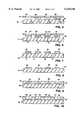
- FIG. 1is a plan view of one embodiment of a substrate employed by the method of the present invention.
- FIG. 2is a section view of the substrate of FIG. 1 taken along line II--II, and after a first template has been placed over the substrate.
- FIG. 3is a section view of the substrate and template shown in FIG. 2 after electrically conductive polymer bumps have been formed on a first set of bond pads at the substrate.
- FIG. 4is a section view of the substrate and electrically conductive bumps as shown in FIG. 3, following removal of the template.
- FIG. 5is a section view of the electrically conductive bumps and substrate shown in FIG. 4, and of a second template placed over the substrate and electrically conductive polymer bumps.
- FIG. 6is a section view of the substrate and template shown in FIG. 5 after an electrically conductive bump has been formed on a second set of the bond pads at the substrate.
- FIG. 7is a section view of the electrically conductive bumps formed on the bond pads of the substrate after the second template has been removed.
- FIG. 8is a section view of a second substrate suitable for use in an optional embodiment of the invention.
- FIG. 9is a section view of the substrate shown in FIG. 8 following coating of the substrate and bond pads of the substrate with an organic protective layer, according to the method of the present invention.
- FIG. 10is a section view on the substrate and organic protective layer shown in FIG. 9 following laser ablation of portions of the organic protective layer which cover the bond pads of the substrate.
- FIG. 11is a section view of the substrate and laser ablated organic protective layer of FIG. 10, and of the substrate of FIG. 7, having electrically conductive polymer bumps at the bond pads of the substrate.
- FIG. 12is a section view of an electrical circuit formed by contacting the electrically conductive polymer bumps at the first substrate with the bond pads at the second substrate, whereby void space between the first and second substrates is eliminated by the organic protective layer formed on the second substrate.
- a suitable substrate 10such as that shown in FIG. 1, has electrical bond pads 12,14,16,18 on upper planar surface 20 of the substrate.
- suitable substratesinclude flip chip dies, lead frames, multichip modules printed circuit boards, etc.
- Substrate 10is formed of a suitable material, such as silicon, gallium arsenide, germanium or some other conventional semiconductor material.
- a first template 22is placed over upper planer surface 20 of substrate.
- First template 22has openings 24,26 which are aligned with bond pads. 14,18 which are a first set of the bond pads of substrate 10. Consequently, at least one bond pad of substrate 10 is covered by template 22.
- the first set of bond pads of substrate 10are those bond pads which are exposed by placement of the first template on substrate 10.
- the second set of the bond padsare those bond pads which are covered by placement of the first template on substrate 10.
- at least one bond pad of the second set of bond padsis located between bond pads of the first set.
- First template 22is suitable for screen printing electrically conductive polymer bumps onto the first portion of bond pads of substrate 10.
- An example of a suitable templateis a Laseretch stencil, commercially available from IRI.
- the distance between the centers of bond pads of the first portion from the centers of bond pads of the second portionis in the range of between about 1 and five mils.
- the pitch between bond pads of the second setis greater than about two mils. It is to be understood, however, that the pitch between bond pads of the first portion from bond pads of the second set can be greater than five mils.
- bond pads on substrate 10can be arranged peripherally, in a staggered arrangement, or in an array on upper planar surface of the substrate 10.
- electrically conductive polymer bumps 28,30are formed by directing the electrically conductive polymer through openings 24,26, respectively, of template 22 and onto the first set of the bond pads of substrate 10.
- electrically conductive bumps 28,30are formed of a B-stage polymer or a thermoplastic polymer.
- the electrically conductive polymer bumpscan be gold-filled, silver-filled, or filled with some other electrically conductive material.
- the height of electrically conductive polymer bumps 28,30is about flush with an upper surface 32 of template 22. Template 22 is then removed from substrate 10, thereby leaving free-standing electrically conductive polymer bumps 28,30 on the first set of bond pads of substrate 10, as shown in FIG. 4.
- Second template 34is then placed over substrate 10 and electrically conductive polymer bumps 28,30 at the first set of the bond pads, as shown in FIG. 5.
- Second template 34includes openings 36,38.
- the openings of second template 34are aligned with bond pads 12,16, which represent the second set of the bond pads of substrate 10.
- Second template 34is of the same type of construction, and is fabricated in the same way, as first template 22, except that openings 36,38 of second template 34 are aligned with the second set of bond pads, rather than with the first set of bond pads.
- electrically conductive polymer bumps 40,42are formed by a suitable method, such as stenciling, whereby the electrically conductive polymer is directed through openings 36,38 of second template 34 onto the second set of bond pads, which are bond pads 12,16.
- the height of the electrically conductive polymer bumps 40,42 formed on the second set of the bond padsis about the same as that of the electrically-conductive bumps formed on the first set of the bond pads. Any resultant differences in heights between the electrically conductive polymer bumps formed on the first set of bond pads and of the bumps formed on the second set of bond pads is small enough not to affect the formation of electrical interconnections between substrate 10 and a second substrate during fabrication of an electrical circuit.
- electrically conductive polymer bumps 28,30,40,42extend from the first and second sets of the bond pads of substrate 10.
- an organic protective layercan be formed on substrate 10 either prior to, or following, formation of the electrically conductive polymer bumps, as described in U.S. Pat. No. 5,237,130, the teachings of which are incorporated by reference. Generally, however an organic protective layer will be formed on upper planar surface 20 of substrate 10 only as a heat sink, which is employed during operation of the fabricated electrical circuit that includes substrate 10.
- second substrate 44includes bond pads 46,48,50,52.
- suitable substratesinclude flip chips, lead frames, multichip modules and printed circuit boards.
- Bond pads 46,48,50,52can be arranged in a peripheral pattern about upper surface 54 of substrate 44, in a staggered pattern, or in an array.
- bond pads 46,48,50,52 of second substrate 44are arranged for alignment with electrically conductive polymer bumps 28,30,40,42 of first substrate 10.
- Organic protective layer 56is formed over substrate 44 and bond pads 46,48,50,52 of substrate 44 by a suitable method.
- substrate 44can be passivated with silicon nitride or an oxide layer, not shown, before formation of organic protective layer 56.
- Organic protective layer 56is preferably a dielectric polymer.
- An example of an organic material suitable for application in the present inventionis Epo-Tek®, manufactured Epoxy Technology, Inc.
- Organic protective layer 56is preferably polymerized by application of heat or other conventional means.
- Organic protective layer 56passivates and thereby insulates and protects underlying surface 54 of second substrate 44.
- Bond pads 46,48,50,52 of second substrate 44are then exposed by laser ablation of organic protective layer 44 to form openings 58,60,62,64.
- laser ablationis performed by employing an Excimer-type laser.
- the thickness of organic protective layer 56is about equal to the combined thickness of bond pads 12,14,16,18,46,48,50,52 of first and second substrates, and of electrically conductive polymer bumps 28,30,40,42.
- electrically conductive polymer bumps 28,30,40,42 at bond pads 12,14,16,18 of first substrate 10are aligned with bond pads 46,48,50,52 of second substrate 44.
- electrically conductive polymer bumps 28,30,40,42are contacted with bond pads 46,48,50,52 of second substrate 44, thereby forming an electrical circuit of the first and second substrates.
- an adhesivenot shown, is formed on bond pads 46,48,50,52 of second substrate 44 before electrically conductive polymer bumps 28,30,40,42 are contacted to bond pads 46,48,50,52 of second substrate 44.
- adhesives which can be usedincludes thermosets, thermoplastics and polymer thick film. Adhesive is typically formed on substrate bond pads 46,48,50,52 by screen printing, templating, or by some other conventional method.
- first substrate 10is aligned over second substrate 44 by an aligner bonder, such as a Model M-8 aligner bonder, manufactured by Research Devices, Division of the American Optical corporation.
- an aligner bondersuch as a Model M-8 aligner bonder, manufactured by Research Devices, Division of the American Optical corporation.
Landscapes
- Engineering & Computer Science (AREA)
- Microelectronics & Electronic Packaging (AREA)
- Computer Hardware Design (AREA)
- Power Engineering (AREA)
- Manufacturing & Machinery (AREA)
- Physics & Mathematics (AREA)
- Condensed Matter Physics & Semiconductors (AREA)
- General Physics & Mathematics (AREA)
- Ceramic Engineering (AREA)
- Chemical & Material Sciences (AREA)
- Materials Engineering (AREA)
- Wire Bonding (AREA)
Abstract
Description
Claims (13)
Priority Applications (1)
| Application Number | Priority Date | Filing Date | Title |
|---|---|---|---|
| US09/264,396US6138348A (en) | 1989-12-18 | 1999-03-08 | Method of forming electrically conductive polymer interconnects on electrical substrates |
Applications Claiming Priority (6)
| Application Number | Priority Date | Filing Date | Title |
|---|---|---|---|
| US07/452,191US5074947A (en) | 1989-12-18 | 1989-12-18 | Flip chip technology using electrically conductive polymers and dielectrics |
| US07/810,513US5237130A (en) | 1989-12-18 | 1991-12-19 | Flip chip technology using electrically conductive polymers and dielectrics |
| US10749893A | 1993-08-17 | 1993-08-17 | |
| US38986295A | 1995-02-23 | 1995-02-23 | |
| US08/503,622US5879761A (en) | 1989-12-18 | 1995-07-18 | Method for forming electrically conductive polymer interconnects on electrical substrates |
| US09/264,396US6138348A (en) | 1989-12-18 | 1999-03-08 | Method of forming electrically conductive polymer interconnects on electrical substrates |
Related Parent Applications (1)
| Application Number | Title | Priority Date | Filing Date |
|---|---|---|---|
| US08/503,622DivisionUS5879761A (en) | 1989-12-18 | 1995-07-18 | Method for forming electrically conductive polymer interconnects on electrical substrates |
Publications (1)
| Publication Number | Publication Date |
|---|---|
| US6138348Atrue US6138348A (en) | 2000-10-31 |
Family
ID=27380320
Family Applications (4)
| Application Number | Title | Priority Date | Filing Date |
|---|---|---|---|
| US08/387,024Expired - LifetimeUS5611140A (en) | 1989-12-18 | 1995-02-10 | Method of forming electrically conductive polymer interconnects on electrical substrates |
| US08/503,622Expired - Fee RelatedUS5879761A (en) | 1989-12-18 | 1995-07-18 | Method for forming electrically conductive polymer interconnects on electrical substrates |
| US08/818,634Expired - Fee RelatedUS5918364A (en) | 1989-12-18 | 1997-03-14 | Method of forming electrically conductive polymer interconnects on electrical substrates |
| US09/264,396Expired - Fee RelatedUS6138348A (en) | 1989-12-18 | 1999-03-08 | Method of forming electrically conductive polymer interconnects on electrical substrates |
Family Applications Before (3)
| Application Number | Title | Priority Date | Filing Date |
|---|---|---|---|
| US08/387,024Expired - LifetimeUS5611140A (en) | 1989-12-18 | 1995-02-10 | Method of forming electrically conductive polymer interconnects on electrical substrates |
| US08/503,622Expired - Fee RelatedUS5879761A (en) | 1989-12-18 | 1995-07-18 | Method for forming electrically conductive polymer interconnects on electrical substrates |
| US08/818,634Expired - Fee RelatedUS5918364A (en) | 1989-12-18 | 1997-03-14 | Method of forming electrically conductive polymer interconnects on electrical substrates |
Country Status (1)
| Country | Link |
|---|---|
| US (4) | US5611140A (en) |
Cited By (42)
| Publication number | Priority date | Publication date | Assignee | Title |
|---|---|---|---|---|
| US20010023779A1 (en)* | 2000-02-09 | 2001-09-27 | Yasuhiro Sugaya | Transfer material, method for producing the same and wiring substrate produced by using the same |
| US6341418B1 (en)* | 1999-04-29 | 2002-01-29 | International Business Machines Corporation | Method for direct chip attach by solder bumps and an underfill layer |
| US20030025197A1 (en)* | 1999-12-21 | 2003-02-06 | Makoto Imai | Cooling structure for multichip module |
| US20030049886A1 (en)* | 2001-09-07 | 2003-03-13 | Salmon Peter C. | Electronic system modules and method of fabrication |
| US6586843B2 (en) | 2001-11-08 | 2003-07-01 | Intel Corporation | Integrated circuit device with covalently bonded connection structure |
| US6651319B2 (en)* | 2001-09-07 | 2003-11-25 | Visteon Global Technologies, Inc. | Compliant standoff for low pressure sensing device |
| US20040005770A1 (en)* | 2002-07-08 | 2004-01-08 | Farnworth Warren M. | Semiconductor devices with permanent polymer stencil and method for manufacturing the same |
| US20040070080A1 (en)* | 2001-02-27 | 2004-04-15 | Chippac, Inc | Low cost, high performance flip chip package structure |
| US20040082108A1 (en)* | 2002-10-29 | 2004-04-29 | International Business Machines Corporation | Method of making an electronic package |
| US20040092141A1 (en)* | 2001-09-07 | 2004-05-13 | Salmon Peter C. | Electronic system modules and method of fabrication |
| US20040164649A1 (en)* | 2003-02-25 | 2004-08-26 | Palo Alto Research Center Incorporated | Bimorph MEMS devices and methods to make same |
| US20040176924A1 (en)* | 2003-03-07 | 2004-09-09 | Salmon Peter C. | Apparatus and method for testing electronic systems |
| US20040189170A1 (en)* | 2001-02-15 | 2004-09-30 | Integral Technologies, Inc. | Low cost lighting circuits manufactured from conductive loaded resin-based materials |
| US20040217472A1 (en)* | 2001-02-16 | 2004-11-04 | Integral Technologies, Inc. | Low cost chip carrier with integrated antenna, heat sink, or EMI shielding functions manufactured from conductive loaded resin-based materials |
| US20040231878A1 (en)* | 2003-05-19 | 2004-11-25 | Takaaki Higashida | Electronic circuit connecting structure, and its connecting method |
| US20050040513A1 (en)* | 2003-08-20 | 2005-02-24 | Salmon Peter C. | Copper-faced modules, imprinted copper circuits, and their application to supercomputers |
| US20050056944A1 (en)* | 2001-02-27 | 2005-03-17 | Chippac, Inc. | Super-thin high speed flip chip package |
| US20050162045A1 (en)* | 2003-02-25 | 2005-07-28 | Palo Alto Research Center Incorporated | Methods to make thick film single elements and arrays |
| US20050184376A1 (en)* | 2004-02-19 | 2005-08-25 | Salmon Peter C. | System in package |
| US20050255722A1 (en)* | 2004-05-07 | 2005-11-17 | Salmon Peter C | Micro blade assembly |
| US20060057827A1 (en)* | 2003-03-05 | 2006-03-16 | Lauri Huhtasalo | Method for manufacturing in electrically conductive pattern |
| US20060068521A1 (en)* | 2004-09-29 | 2006-03-30 | Song-Hua Shi | Method of fabricating microelectronic package using no-flow underfill technology and microelectronic package formed according to the method |
| US20060121255A1 (en)* | 2004-12-06 | 2006-06-08 | Samsung Electro-Mechanics Co., Ltd. | Parallel multilayer printed circuit board having interlayer conductivity due to via ports and method of fabricating same |
| KR100587389B1 (en)* | 2000-12-23 | 2006-06-08 | 앰코 테크놀로지 코리아 주식회사 | Stacked Semiconductor Packages |
| US20060131728A1 (en)* | 2004-12-16 | 2006-06-22 | Salmon Peter C | Repairable three-dimensional semiconductor subsystem |
| US20070007983A1 (en)* | 2005-01-06 | 2007-01-11 | Salmon Peter C | Semiconductor wafer tester |
| US20070023889A1 (en)* | 2005-08-01 | 2007-02-01 | Salmon Peter C | Copper substrate with feedthroughs and interconnection circuits |
| US20070023904A1 (en)* | 2005-08-01 | 2007-02-01 | Salmon Peter C | Electro-optic interconnection apparatus and method |
| US20070023923A1 (en)* | 2005-08-01 | 2007-02-01 | Salmon Peter C | Flip chip interface including a mixed array of heat bumps and signal bumps |
| US20070289706A1 (en)* | 2006-06-16 | 2007-12-20 | Fujitsu Limited | Process for producing multilayer board |
| US20080213613A1 (en)* | 2004-12-20 | 2008-09-04 | Takeo Kuramoto | Solder Precoating Method and Workpiece For Electronic Equipment |
| US20080251280A1 (en)* | 2006-09-12 | 2008-10-16 | Fujikura Ltd. | Soldering structure between circuit boards |
| US20080264675A1 (en)* | 2007-04-25 | 2008-10-30 | Foxconn Advanced Technology Inc. | Printed circuit board and method for manufacturing the same |
| US20090004501A1 (en)* | 2007-06-29 | 2009-01-01 | Hon Hai Precision Industry Co., Ltd. | Pad and circuit board, electronic device using same |
| US20090051048A1 (en)* | 2007-08-21 | 2009-02-26 | Advanced Semiconductor Engineering, Inc. | Package structure and manufacturing method thereof |
| US7586747B2 (en) | 2005-08-01 | 2009-09-08 | Salmon Technologies, Llc. | Scalable subsystem architecture having integrated cooling channels |
| CN100565864C (en)* | 2008-03-06 | 2009-12-02 | 日月光半导体制造股份有限公司 | Package structure and manufacturing method thereof |
| WO2009140252A3 (en)* | 2008-05-12 | 2010-02-25 | Texas Instruments Incorporated | Through-silicon enabled die stacking scheme |
| US20110074028A1 (en)* | 2004-10-07 | 2011-03-31 | Stats Chippac, Ltd. | Semiconductor Device and Method of Dissipating Heat From Thin Package-on-Package Mounted to Substrate |
| USRE44438E1 (en) | 2001-02-27 | 2013-08-13 | Stats Chippac, Ltd. | Semiconductor device and method of dissipating heat from thin package-on-package mounted to substrate |
| USRE44941E1 (en)* | 2004-06-26 | 2014-06-10 | Emagin Corporation | Method of clearing electrical contact pads in thin film sealed OLED devices |
| US9653623B2 (en) | 2014-12-02 | 2017-05-16 | Samsung Electronics Co., Ltd. | Methods of manufacturing a semiconductor device |
Families Citing this family (138)
| Publication number | Priority date | Publication date | Assignee | Title |
|---|---|---|---|---|
| US5657206A (en)* | 1994-06-23 | 1997-08-12 | Cubic Memory, Inc. | Conductive epoxy flip-chip package and method |
| US5829124A (en)* | 1995-12-29 | 1998-11-03 | International Business Machines Corporation | Method for forming metallized patterns on the top surface of a printed circuit board |
| US6148512A (en)* | 1996-04-22 | 2000-11-21 | Motorola, Inc. | Method for attaching an electronic device |
| US6558979B2 (en)* | 1996-05-21 | 2003-05-06 | Micron Technology, Inc. | Use of palladium in IC manufacturing with conductive polymer bump |
| US5822856A (en)* | 1996-06-28 | 1998-10-20 | International Business Machines Corporation | Manufacturing circuit board assemblies having filled vias |
| JPH1041694A (en)* | 1996-07-25 | 1998-02-13 | Sharp Corp | Substrate mounting structure of semiconductor element and mounting method thereof |
| JP3322575B2 (en)* | 1996-07-31 | 2002-09-09 | 太陽誘電株式会社 | Hybrid module and manufacturing method thereof |
| JP3928753B2 (en) | 1996-08-06 | 2007-06-13 | 日立化成工業株式会社 | Multi-chip mounting method and manufacturing method of chip with adhesive |
| US5956605A (en)* | 1996-09-20 | 1999-09-21 | Micron Technology, Inc. | Use of nitrides for flip-chip encapsulation |
| DE19642563C1 (en)* | 1996-10-15 | 1998-02-26 | Siemens Ag | Chip card with a contact zone and method for producing such a chip card |
| US6400575B1 (en)* | 1996-10-21 | 2002-06-04 | Alpine Microsystems, Llc | Integrated circuits packaging system and method |
| ES2164226T3 (en)* | 1996-12-20 | 2002-02-16 | Cit Alcatel | PROCEDURE TO PRODUCE METAL DISTANCING SUPPORTS IN A PRINTED CIRCUIT PLATE. |
| JP3094948B2 (en) | 1997-05-26 | 2000-10-03 | 日本電気株式会社 | Method of connecting circuit board for mounting semiconductor element and semiconductor element |
| US5963144A (en)* | 1997-05-30 | 1999-10-05 | Single Chip Systems Corp. | Cloaking circuit for use in a radiofrequency identification and method of cloaking RFID tags to increase interrogation reliability |
| US6162661A (en)* | 1997-05-30 | 2000-12-19 | Tessera, Inc. | Spacer plate solder ball placement fixture and methods therefor |
| US6026566A (en)* | 1997-06-05 | 2000-02-22 | Cooper Industries, Inc. | Stenciling method and apparatus for PC board repair |
| US6297559B1 (en) | 1997-07-10 | 2001-10-02 | International Business Machines Corporation | Structure, materials, and applications of ball grid array interconnections |
| US6120885A (en)* | 1997-07-10 | 2000-09-19 | International Business Machines Corporation | Structure, materials, and methods for socketable ball grid |
| US6337522B1 (en)* | 1997-07-10 | 2002-01-08 | International Business Machines Corporation | Structure employing electrically conductive adhesives |
| US6156408A (en)* | 1997-08-29 | 2000-12-05 | Motorola, Inc. | Device for reworkable direct chip attachment |
| US6740960B1 (en)* | 1997-10-31 | 2004-05-25 | Micron Technology, Inc. | Semiconductor package including flex circuit, interconnects and dense array external contacts |
| US6097087A (en)* | 1997-10-31 | 2000-08-01 | Micron Technology, Inc. | Semiconductor package including flex circuit, interconnects and dense array external contacts |
| US6096578A (en)* | 1997-11-05 | 2000-08-01 | Texas Instruments Incorporated | Stress relief matrix for integrated circuit packaging |
| US6225205B1 (en)* | 1998-01-22 | 2001-05-01 | Ricoh Microelectronics Company, Ltd. | Method of forming bump electrodes |
| US6110760A (en)* | 1998-02-12 | 2000-08-29 | Micron Technology, Inc. | Methods of forming electrically conductive interconnections and electrically interconnected substrates |
| US6137063A (en) | 1998-02-27 | 2000-10-24 | Micron Technology, Inc. | Electrical interconnections |
| US6013877A (en)* | 1998-03-12 | 2000-01-11 | Lucent Technologies Inc. | Solder bonding printed circuit boards |
| JP3625646B2 (en)* | 1998-03-23 | 2005-03-02 | 東レエンジニアリング株式会社 | Flip chip mounting method |
| US6297564B1 (en) | 1998-04-24 | 2001-10-02 | Amerasia International Technology, Inc. | Electronic devices employing adhesive interconnections including plated particles |
| US6580035B1 (en) | 1998-04-24 | 2003-06-17 | Amerasia International Technology, Inc. | Flexible adhesive membrane and electronic device employing same |
| US6406988B1 (en) | 1998-04-24 | 2002-06-18 | Amerasia International Technology, Inc. | Method of forming fine pitch interconnections employing magnetic masks |
| US6108210A (en)* | 1998-04-24 | 2000-08-22 | Amerasia International Technology, Inc. | Flip chip devices with flexible conductive adhesive |
| US6406939B1 (en) | 1998-05-02 | 2002-06-18 | Charles W. C. Lin | Flip chip assembly with via interconnection |
| SG75841A1 (en) | 1998-05-02 | 2000-10-24 | Eriston Invest Pte Ltd | Flip chip assembly with via interconnection |
| US6428650B1 (en) | 1998-06-23 | 2002-08-06 | Amerasia International Technology, Inc. | Cover for an optical device and method for making same |
| US6136128A (en)* | 1998-06-23 | 2000-10-24 | Amerasia International Technology, Inc. | Method of making an adhesive preform lid for electronic devices |
| US6409859B1 (en) | 1998-06-30 | 2002-06-25 | Amerasia International Technology, Inc. | Method of making a laminated adhesive lid, as for an Electronic device |
| US6399178B1 (en) | 1998-07-20 | 2002-06-04 | Amerasia International Technology, Inc. | Rigid adhesive underfill preform, as for a flip-chip device |
| US6189208B1 (en) | 1998-09-11 | 2001-02-20 | Polymer Flip Chip Corp. | Flip chip mounting technique |
| US6316289B1 (en)* | 1998-11-12 | 2001-11-13 | Amerasia International Technology Inc. | Method of forming fine-pitch interconnections employing a standoff mask |
| TW522536B (en) | 1998-12-17 | 2003-03-01 | Wen-Chiang Lin | Bumpless flip chip assembly with strips-in-via and plating |
| SG82591A1 (en) | 1998-12-17 | 2001-08-21 | Eriston Technologies Pte Ltd | Bumpless flip chip assembly with solder via |
| SG82590A1 (en) | 1998-12-17 | 2001-08-21 | Eriston Technologies Pte Ltd | Bumpless flip chip assembly with strips and via-fill |
| US6785148B1 (en)* | 1998-12-21 | 2004-08-31 | Intel Corporation | Easy mount socket |
| US6524346B1 (en)* | 1999-02-26 | 2003-02-25 | Micron Technology, Inc. | Stereolithographic method for applying materials to electronic component substrates and resulting structures |
| US6410415B1 (en) | 1999-03-23 | 2002-06-25 | Polymer Flip Chip Corporation | Flip chip mounting technique |
| US6258625B1 (en)* | 1999-05-18 | 2001-07-10 | International Business Machines Corporation | Method of interconnecting electronic components using a plurality of conductive studs |
| US6253675B1 (en) | 1999-06-29 | 2001-07-03 | Carl P. Mayer | Solder paste stenciling apparatus and method of use for rework |
| US6861345B2 (en)* | 1999-08-27 | 2005-03-01 | Micron Technology, Inc. | Method of disposing conductive bumps onto a semiconductor device |
| KR100327152B1 (en)* | 1999-10-14 | 2002-03-13 | 박호군 | Method for Making Conductive Polymer Composite Films |
| TW511122B (en)* | 1999-12-10 | 2002-11-21 | Ebara Corp | Method for mounting semiconductor device and structure thereof |
| SG99331A1 (en)* | 2000-01-13 | 2003-10-27 | Hitachi Ltd | Method of producing electronic part with bumps and method of producing elctronic part |
| US6551861B1 (en) | 2000-08-22 | 2003-04-22 | Charles W. C. Lin | Method of making a semiconductor chip assembly by joining the chip to a support circuit with an adhesive |
| US6562709B1 (en) | 2000-08-22 | 2003-05-13 | Charles W. C. Lin | Semiconductor chip assembly with simultaneously electroplated contact terminal and connection joint |
| US6436734B1 (en) | 2000-08-22 | 2002-08-20 | Charles W. C. Lin | Method of making a support circuit for a semiconductor chip assembly |
| US6403460B1 (en) | 2000-08-22 | 2002-06-11 | Charles W. C. Lin | Method of making a semiconductor chip assembly |
| US6660626B1 (en) | 2000-08-22 | 2003-12-09 | Charles W. C. Lin | Semiconductor chip assembly with simultaneously electrolessly plated contact terminal and connection joint |
| US6402970B1 (en) | 2000-08-22 | 2002-06-11 | Charles W. C. Lin | Method of making a support circuit for a semiconductor chip assembly |
| US6350633B1 (en) | 2000-08-22 | 2002-02-26 | Charles W. C. Lin | Semiconductor chip assembly with simultaneously electroplated contact terminal and connection joint |
| US6562657B1 (en) | 2000-08-22 | 2003-05-13 | Charles W. C. Lin | Semiconductor chip assembly with simultaneously electrolessly plated contact terminal and connection joint |
| WO2002017392A2 (en)* | 2000-08-24 | 2002-02-28 | Polymer Flip Chip Corporation | Polymer redistribution of flip chip bond pads |
| US6350386B1 (en) | 2000-09-20 | 2002-02-26 | Charles W. C. Lin | Method of making a support circuit with a tapered through-hole for a semiconductor chip assembly |
| US6511865B1 (en) | 2000-09-20 | 2003-01-28 | Charles W. C. Lin | Method for forming a ball bond connection joint on a conductive trace and conductive pad in a semiconductor chip assembly |
| US6350632B1 (en) | 2000-09-20 | 2002-02-26 | Charles W. C. Lin | Semiconductor chip assembly with ball bond connection joint |
| US6544813B1 (en) | 2000-10-02 | 2003-04-08 | Charles W. C. Lin | Method of making a semiconductor chip assembly with a conductive trace subtractively formed before and after chip attachment |
| US6448108B1 (en) | 2000-10-02 | 2002-09-10 | Charles W. C. Lin | Method of making a semiconductor chip assembly with a conductive trace subtractively formed before and after chip attachment |
| US7190080B1 (en) | 2000-10-13 | 2007-03-13 | Bridge Semiconductor Corporation | Semiconductor chip assembly with embedded metal pillar |
| US7129113B1 (en) | 2000-10-13 | 2006-10-31 | Bridge Semiconductor Corporation | Method of making a three-dimensional stacked semiconductor package with a metal pillar in an encapsulant aperture |
| US7071089B1 (en) | 2000-10-13 | 2006-07-04 | Bridge Semiconductor Corporation | Method of making a semiconductor chip assembly with a carved bumped terminal |
| US6440835B1 (en) | 2000-10-13 | 2002-08-27 | Charles W. C. Lin | Method of connecting a conductive trace to a semiconductor chip |
| US7075186B1 (en) | 2000-10-13 | 2006-07-11 | Bridge Semiconductor Corporation | Semiconductor chip assembly with interlocked contact terminal |
| US7319265B1 (en) | 2000-10-13 | 2008-01-15 | Bridge Semiconductor Corporation | Semiconductor chip assembly with precision-formed metal pillar |
| US6548393B1 (en) | 2000-10-13 | 2003-04-15 | Charles W. C. Lin | Semiconductor chip assembly with hardened connection joint |
| US6949408B1 (en) | 2000-10-13 | 2005-09-27 | Bridge Semiconductor Corporation | Method of connecting a conductive trace and an insulative base to a semiconductor chip using multiple etch steps |
| US6872591B1 (en) | 2000-10-13 | 2005-03-29 | Bridge Semiconductor Corporation | Method of making a semiconductor chip assembly with a conductive trace and a substrate |
| US6537851B1 (en) | 2000-10-13 | 2003-03-25 | Bridge Semiconductor Corporation | Method of connecting a bumped compliant conductive trace to a semiconductor chip |
| US7094676B1 (en) | 2000-10-13 | 2006-08-22 | Bridge Semiconductor Corporation | Semiconductor chip assembly with embedded metal pillar |
| US6740576B1 (en) | 2000-10-13 | 2004-05-25 | Bridge Semiconductor Corporation | Method of making a contact terminal with a plated metal peripheral sidewall portion for a semiconductor chip assembly |
| US7129575B1 (en) | 2000-10-13 | 2006-10-31 | Bridge Semiconductor Corporation | Semiconductor chip assembly with bumped metal pillar |
| US6699780B1 (en) | 2000-10-13 | 2004-03-02 | Bridge Semiconductor Corporation | Method of connecting a conductive trace to a semiconductor chip using plasma undercut etching |
| US6492252B1 (en) | 2000-10-13 | 2002-12-10 | Bridge Semiconductor Corporation | Method of connecting a bumped conductive trace to a semiconductor chip |
| US6984576B1 (en) | 2000-10-13 | 2006-01-10 | Bridge Semiconductor Corporation | Method of connecting an additively and subtractively formed conductive trace and an insulative base to a semiconductor chip |
| US6576539B1 (en) | 2000-10-13 | 2003-06-10 | Charles W.C. Lin | Semiconductor chip assembly with interlocked conductive trace |
| US7009297B1 (en) | 2000-10-13 | 2006-03-07 | Bridge Semiconductor Corporation | Semiconductor chip assembly with embedded metal particle |
| US6667229B1 (en) | 2000-10-13 | 2003-12-23 | Bridge Semiconductor Corporation | Method of connecting a bumped compliant conductive trace and an insulative base to a semiconductor chip |
| US6673710B1 (en) | 2000-10-13 | 2004-01-06 | Bridge Semiconductor Corporation | Method of connecting a conductive trace and an insulative base to a semiconductor chip |
| US6576493B1 (en) | 2000-10-13 | 2003-06-10 | Bridge Semiconductor Corporation | Method of connecting a conductive trace and an insulative base to a semiconductor chip using multiple etch steps |
| US7264991B1 (en) | 2000-10-13 | 2007-09-04 | Bridge Semiconductor Corporation | Method of connecting a conductive trace to a semiconductor chip using conductive adhesive |
| US6876072B1 (en) | 2000-10-13 | 2005-04-05 | Bridge Semiconductor Corporation | Semiconductor chip assembly with chip in substrate cavity |
| US6908788B1 (en) | 2000-10-13 | 2005-06-21 | Bridge Semiconductor Corporation | Method of connecting a conductive trace to a semiconductor chip using a metal base |
| US7132741B1 (en) | 2000-10-13 | 2006-11-07 | Bridge Semiconductor Corporation | Semiconductor chip assembly with carved bumped terminal |
| US7414319B2 (en)* | 2000-10-13 | 2008-08-19 | Bridge Semiconductor Corporation | Semiconductor chip assembly with metal containment wall and solder terminal |
| US7262082B1 (en) | 2000-10-13 | 2007-08-28 | Bridge Semiconductor Corporation | Method of making a three-dimensional stacked semiconductor package with a metal pillar and a conductive interconnect in an encapsulant aperture |
| US6444489B1 (en) | 2000-12-15 | 2002-09-03 | Charles W. C. Lin | Semiconductor chip assembly with bumped molded substrate |
| US6494361B1 (en)* | 2001-01-26 | 2002-12-17 | Amkor Technology, Inc. | Semiconductor module package substrate fabrication method |
| US6445075B1 (en) | 2001-01-26 | 2002-09-03 | Amkor Technology, Inc. | Semiconductor module package substrate |
| US6653170B1 (en) | 2001-02-06 | 2003-11-25 | Charles W. C. Lin | Semiconductor chip assembly with elongated wire ball bonded to chip and electrolessly plated to support circuit |
| US6648213B1 (en) | 2001-03-05 | 2003-11-18 | Saturn Electronics & Engineering, Inc. | Manufacturing method for attaching components to a substrate |
| US20020180029A1 (en)* | 2001-04-25 | 2002-12-05 | Hideki Higashitani | Semiconductor device with intermediate connector |
| US6742248B2 (en)* | 2001-05-14 | 2004-06-01 | The Boeing Company | Method of forming a soldered electrical connection |
| JP3729092B2 (en)* | 2001-06-19 | 2005-12-21 | ソニー株式会社 | Conductive bonding material, multilayer printed wiring board, and method for manufacturing multilayer printed wiring board |
| US7211103B2 (en)* | 2002-04-11 | 2007-05-01 | Second Sight Medical Products, Inc. | Biocompatible bonding method and electronics package suitable for implantation |
| US7142909B2 (en)* | 2002-04-11 | 2006-11-28 | Second Sight Medical Products, Inc. | Biocompatible bonding method and electronics package suitable for implantation |
| EP1664731B1 (en)* | 2003-03-21 | 2012-02-22 | MEAS France | Resonator sensor assembly |
| US20050077603A1 (en)* | 2003-10-08 | 2005-04-14 | Dylan Yu | Method and structure for a wafer level packaging |
| US7993983B1 (en) | 2003-11-17 | 2011-08-09 | Bridge Semiconductor Corporation | Method of making a semiconductor chip assembly with chip and encapsulant grinding |
| US7538415B1 (en) | 2003-11-20 | 2009-05-26 | Bridge Semiconductor Corporation | Semiconductor chip assembly with bumped terminal, filler and insulative base |
| US7425759B1 (en) | 2003-11-20 | 2008-09-16 | Bridge Semiconductor Corporation | Semiconductor chip assembly with bumped terminal and filler |
| US7049170B2 (en)* | 2003-12-17 | 2006-05-23 | Tru-Si Technologies, Inc. | Integrated circuits and packaging substrates with cavities, and attachment methods including insertion of protruding contact pads into cavities |
| US7170187B2 (en)* | 2004-08-31 | 2007-01-30 | International Business Machines Corporation | Low stress conductive polymer bump |
| US7750483B1 (en) | 2004-11-10 | 2010-07-06 | Bridge Semiconductor Corporation | Semiconductor chip assembly with welded metal pillar and enlarged plated contact terminal |
| US7446419B1 (en) | 2004-11-10 | 2008-11-04 | Bridge Semiconductor Corporation | Semiconductor chip assembly with welded metal pillar of stacked metal balls |
| US7268421B1 (en) | 2004-11-10 | 2007-09-11 | Bridge Semiconductor Corporation | Semiconductor chip assembly with welded metal pillar that includes enlarged ball bond |
| US7743963B1 (en) | 2005-03-01 | 2010-06-29 | Amerasia International Technology, Inc. | Solderable lid or cover for an electronic circuit |
| TWI261325B (en)* | 2005-03-25 | 2006-09-01 | Advanced Semiconductor Eng | Package structure of semiconductor and wafer-level formation thereof |
| US20070029655A1 (en)* | 2005-08-02 | 2007-02-08 | Chang Hong T | Jig structure for manufacturin a stacked memory card |
| US7385282B2 (en)* | 2005-10-19 | 2008-06-10 | Chipmos Technologies Inc. | Stacked-type chip package structure |
| AU2007284422B2 (en) | 2006-08-18 | 2011-06-02 | Second Sight Medical Products, Inc. | Package for an implantable neural stimulation device |
| US7494843B1 (en) | 2006-12-26 | 2009-02-24 | Bridge Semiconductor Corporation | Method of making a semiconductor chip assembly with thermal conductor and encapsulant grinding |
| US7811863B1 (en) | 2006-10-26 | 2010-10-12 | Bridge Semiconductor Corporation | Method of making a semiconductor chip assembly with metal pillar and encapsulant grinding and heat sink attachment |
| US20080176428A1 (en)* | 2007-01-24 | 2008-07-24 | Brandenburg Scott D | Connector applied underfill |
| US9220169B2 (en)* | 2007-06-21 | 2015-12-22 | Second Sight Medical Products, Inc. | Biocompatible electroplated interconnection electronics package suitable for implantation |
| AU2007355605B2 (en) | 2007-06-25 | 2012-04-26 | Second Sight Medical Products, Inc. | Method for providing hermetic electrical feedthrough |
| US7799612B2 (en)* | 2007-06-25 | 2010-09-21 | Spansion Llc | Process applying die attach film to singulated die |
| EP2453726A1 (en)* | 2009-06-01 | 2012-05-16 | Sumitomo Electric Industries, Ltd. | Connection method, connection structure, and electronic device |
| US8138019B2 (en)* | 2009-11-03 | 2012-03-20 | Toyota Motor Engineering & Manufactruing North America, Inc. | Integrated (multilayer) circuits and process of producing the same |
| EP2597670B1 (en)* | 2010-03-31 | 2016-03-30 | EV Group E. Thallner GmbH | Method for permanently connecting two metal surfaces |
| US8193610B2 (en) | 2010-08-10 | 2012-06-05 | Stats Chippac, Ltd. | Semiconductor device and method of forming B-stage conductive polymer over contact pads of semiconductor die in Fo-WLCSP |
| DE102012103430B4 (en)* | 2012-04-19 | 2015-10-22 | Ev Group E. Thallner Gmbh | Method of tying chips onto a substrate |
| US9024526B1 (en) | 2012-06-11 | 2015-05-05 | Imaging Systems Technology, Inc. | Detector element with antenna |
| US9496234B1 (en) | 2015-06-17 | 2016-11-15 | Globalfoundries Inc. | Wafer-level chip-scale package structure utilizing conductive polymer |
| CN109478580B (en)* | 2016-08-22 | 2021-07-09 | 歌尔股份有限公司 | Micro light emitting diode transfer method, manufacturing method and device |
| IT201700055942A1 (en) | 2017-05-23 | 2018-11-23 | St Microelectronics Srl | PROCEDURE FOR MANUFACTURING SEMICONDUCTOR, EQUIPMENT AND CORRESPONDENT CIRCUIT DEVICES |
| IT201700055983A1 (en) | 2017-05-23 | 2018-11-23 | St Microelectronics Srl | PROCEDURE FOR PRODUCING SEMICONDUCTOR, SEMICONDUCTOR AND CORRESPONDENT CIRCUIT DEVICES |
| JP7185252B2 (en)* | 2018-01-31 | 2022-12-07 | 三国電子有限会社 | Method for producing connection structure |
| US10923365B2 (en)* | 2018-10-28 | 2021-02-16 | Richwave Technology Corp. | Connection structure and method for forming the same |
| KR102730308B1 (en)* | 2019-01-30 | 2024-11-15 | 에스케이하이닉스 주식회사 | Semiconductor memory device and method of manufacturing the same |
| CN115602651A (en)* | 2021-07-09 | 2023-01-13 | 联华电子股份有限公司(Tw) | Bonded semiconductor structure and method of making the same |
Citations (84)
| Publication number | Priority date | Publication date | Assignee | Title |
|---|---|---|---|---|
| US2014524A (en)* | 1933-04-28 | 1935-09-17 | Western Electric Co | Article |
| US2774747A (en)* | 1951-04-05 | 1956-12-18 | Int Standard Electric Corp | Electrically conducting cements containing epoxy resins and silver |
| US3401126A (en)* | 1965-06-18 | 1968-09-10 | Ibm | Method of rendering noble metal conductive composition non-wettable by solder |
| US3429040A (en)* | 1965-06-18 | 1969-02-25 | Ibm | Method of joining a component to a substrate |
| US3757075A (en)* | 1970-02-03 | 1973-09-04 | Siemens Ag | 7m circuit method for producing small contacts of uniform thickness for tick fil |
| US3971610A (en)* | 1974-05-10 | 1976-07-27 | Technical Wire Products, Inc. | Conductive elastomeric contacts and connectors |
| DE2658302A1 (en)* | 1975-12-26 | 1977-07-07 | Suwa Seikosha Kk | METHOD OF BONDING INTEGRATED CIRCUITS |
| US4113981A (en)* | 1974-08-14 | 1978-09-12 | Kabushiki Kaisha Seikosha | Electrically conductive adhesive connecting arrays of conductors |
| US4157932A (en)* | 1976-11-04 | 1979-06-12 | Canon Kabushiki Kaisha | Connecting method |
| JPS56167340A (en)* | 1980-05-27 | 1981-12-23 | Toshiba Corp | Junction of semicondctor pellet with substrate |
| FR2492164A1 (en)* | 1980-10-15 | 1982-04-16 | Radiotechnique Compelec | METHOD FOR THE SIMULTANEOUS REALIZATION OF MULTIPLE ELECTRICAL CONNECTIONS, IN PARTICULAR FOR THE ELECTRICAL CONNECTION OF A MICRO-WAFER OF SEMICONDUCTORS |
| JPS57176738A (en)* | 1981-04-23 | 1982-10-30 | Seiko Epson Corp | Connecting structure for flip chip |
| JPS601849A (en)* | 1983-06-17 | 1985-01-08 | Sharp Corp | Connecting method of electronic part |
| US4554033A (en)* | 1984-10-04 | 1985-11-19 | Amp Incorporated | Method of forming an electrical interconnection means |
| US4587038A (en)* | 1980-06-26 | 1986-05-06 | Canon Kabushiki Kaisha | Electro-optic display device and a method of producing the same |
| US4612083A (en)* | 1984-07-20 | 1986-09-16 | Nec Corporation | Process of fabricating three-dimensional semiconductor device |
| JPS61229342A (en)* | 1985-04-03 | 1986-10-13 | Fujitsu Ltd | Connection for bump electrode |
| JPS6210412A (en)* | 1985-07-05 | 1987-01-19 | Yamaha Motor Co Ltd | Oil injector of engine with case |
| US4640981A (en)* | 1984-10-04 | 1987-02-03 | Amp Incorporated | Electrical interconnection means |
| US4648179A (en)* | 1983-06-30 | 1987-03-10 | International Business Machines Corporation | Process of making interconnection structure for semiconductor device |
| DE3702354A1 (en)* | 1986-01-27 | 1987-07-30 | Mitsubishi Electric Corp | SEMICONDUCTOR COMPONENT AND METHOD FOR THE PRODUCTION THEREOF |
| US4695404A (en)* | 1986-04-07 | 1987-09-22 | Amerasia International Technology, Inc. | Hyperconductive filled polymers |
| JPS62283644A (en)* | 1986-05-31 | 1987-12-09 | Mitsubishi Electric Corp | Manufacturing method of semiconductor device |
| US4719140A (en)* | 1984-11-05 | 1988-01-12 | Casio Computer Co., Ltd. | Electronic memory card |
| JPS6328314A (en)* | 1986-07-21 | 1988-02-06 | 井関農機株式会社 | Cabin device in combine harvester |
| JPS63122133A (en)* | 1986-11-11 | 1988-05-26 | Matsushita Electric Ind Co Ltd | Electrical connection method for semiconductor chips |
| US4764804A (en)* | 1986-02-21 | 1988-08-16 | Hitachi, Ltd. | Semiconductor device and process for producing the same |
| JPS63220533A (en)* | 1987-03-10 | 1988-09-13 | Citizen Watch Co Ltd | Mounting structure of ic for clock |
| US4780177A (en)* | 1988-02-05 | 1988-10-25 | General Electric Company | Excimer laser patterning of a novel resist |
| JPS63275127A (en)* | 1987-05-07 | 1988-11-11 | Matsushita Electric Ind Co Ltd | Semiconductor chip mounting body |
| EP0299894A1 (en)* | 1987-07-16 | 1989-01-18 | STMicroelectronics S.A. | Process for making a connection to an integrated circuit contact stud, and contact structure |
| EP0303256A2 (en)* | 1987-08-13 | 1989-02-15 | Shin-Etsu Polymer Co., Ltd. | A method for electrically connecting IC chips, a resinous bump-forming composition used therein and a liquid-crystal display unit electrically connected thereby |
| US4818728A (en)* | 1986-12-03 | 1989-04-04 | Sharp Kabushiki Kaisha | Method of making a hybrid semiconductor device |
| JPH01120039A (en)* | 1987-11-02 | 1989-05-12 | Nippon Telegr & Teleph Corp <Ntt> | Connection of ic chip |
| US4840302A (en)* | 1988-04-15 | 1989-06-20 | International Business Machines Corporation | Chromium-titanium alloy |
| JPH01251643A (en)* | 1988-03-31 | 1989-10-06 | Toshiba Corp | Electrode formation method for semiconductor devices |
| US4872261A (en)* | 1987-12-11 | 1989-10-10 | Digital Equipment Corporation | Method of and apparatus for surface mounting electronic components onto a printed wiring board |
| US4874721A (en)* | 1985-11-11 | 1989-10-17 | Nec Corporation | Method of manufacturing a multichip package with increased adhesive strength |
| JPH01305541A (en)* | 1988-06-02 | 1989-12-08 | Nec Kansai Ltd | Manufacture of semiconductor device |
| JPH0254945A (en)* | 1988-08-19 | 1990-02-23 | Toshiba Corp | electronic components |
| US4926051A (en)* | 1987-03-13 | 1990-05-15 | U.S. Philips Corp. | Thermal-image sensing devices and their manufacture |
| JPH02197698A (en)* | 1989-01-26 | 1990-08-06 | Kubota Ltd | Preventive structure of slipping-off of sheathing of propulsive tube |
| US4967314A (en)* | 1988-03-28 | 1990-10-30 | Prime Computer Inc. | Circuit board construction |
| US4985107A (en)* | 1988-03-01 | 1991-01-15 | Sci Systems, Inc. | Component location device and method for surface-mount printed circuit boards |
| US4991000A (en)* | 1989-08-31 | 1991-02-05 | Bone Robert L | Vertically interconnected integrated circuit chip system |
| JPH0339406A (en)* | 1989-07-07 | 1991-02-20 | Yoshiki Miyasaka | Method and apparatus for manufacturing fine metal fiber |
| JPH0344682A (en)* | 1989-07-12 | 1991-02-26 | Nec Corp | Electrophotographic recording device |
| JPH0356004A (en)* | 1989-07-20 | 1991-03-11 | Mazda Motor Corp | Conveyor |
| US5001302A (en)* | 1988-12-29 | 1991-03-19 | Casio Computer Co., Ltd. | Connecting structure for an electronic part |
| WO1991009419A1 (en)* | 1989-12-18 | 1991-06-27 | Epoxy Technology, Inc. | Flip chip technology using electrically conductive polymers and dielectrics |
| JPH03504064A (en)* | 1989-01-03 | 1991-09-05 | モトローラ・インコーポレーテッド | Manufacturing method for high-density solder bumps and substrate sockets for high-density solder bumps |
| WO1991014014A2 (en)* | 1990-03-13 | 1991-09-19 | Henkel Corporation | Process and composition for treating aluminium |
| US5068714A (en)* | 1989-04-05 | 1991-11-26 | Robert Bosch Gmbh | Method of electrically and mechanically connecting a semiconductor to a substrate using an electrically conductive tacky adhesive and the device so made |
| US5086558A (en)* | 1990-09-13 | 1992-02-11 | International Business Machines Corporation | Direct attachment of semiconductor chips to a substrate with a substrate with a thermoplastic interposer |
| US5090119A (en)* | 1987-12-08 | 1992-02-25 | Matsushita Electric Industrial Co., Ltd. | Method of forming an electrical contact bump |
| EP0473976A1 (en)* | 1990-08-23 | 1992-03-11 | Siemens Aktiengesellschaft | Method and apparatus to bond a semiconductor chip to a carrier |
| WO1992007378A1 (en)* | 1990-10-12 | 1992-04-30 | Robert Bosch Gmbh | Process for producing a hybrid semiconductor structure and semiconductor structure thus produced |
| US5136365A (en)* | 1990-09-27 | 1992-08-04 | Motorola, Inc. | Anisotropic conductive adhesive and encapsulant material |
| US5147210A (en)* | 1988-03-03 | 1992-09-15 | Western Digital Corporation | Polymer film interconnect |
| WO1992021150A1 (en)* | 1991-05-23 | 1992-11-26 | Motorola, Inc. | Integrated circuit chip carrier |
| US5187020A (en)* | 1990-07-31 | 1993-02-16 | Texas Instruments Incorporated | Compliant contact pad |
| US5214844A (en)* | 1990-12-17 | 1993-06-01 | Nchip, Inc. | Method of assembling integrated circuits to a silicon board |
| US5218234A (en)* | 1991-12-23 | 1993-06-08 | Motorola, Inc. | Semiconductor device with controlled spread polymeric underfill |
| US5270253A (en)* | 1986-01-27 | 1993-12-14 | Mitsubishi Denki Kabushiki Kaisha | Method of producing semiconductor device |
| US5279711A (en)* | 1991-07-01 | 1994-01-18 | International Business Machines Corporation | Chip attach and sealing method |
| US5283446A (en)* | 1991-08-30 | 1994-02-01 | Nec Corporation | Compact optical semiconductor module capable of being readily assembled with a high precision |
| US5290423A (en)* | 1992-04-27 | 1994-03-01 | Hughes Aircraft Company | Electrochemical interconnection |
| US5296063A (en)* | 1990-03-20 | 1994-03-22 | Sharp Kabushiki Kaisha | Method for mounting a semiconductor device |
| US5298279A (en)* | 1991-11-14 | 1994-03-29 | Sharp Kabushiki Kaisha | Method for connecting terminals of heat seal film substrate |
| US5304460A (en)* | 1992-09-30 | 1994-04-19 | At&T Bell Laboratories | Anisotropic conductor techniques |
| US5311059A (en)* | 1992-01-24 | 1994-05-10 | Motorola, Inc. | Backplane grounding for flip-chip integrated circuit |
| US5318651A (en)* | 1991-11-27 | 1994-06-07 | Nec Corporation | Method of bonding circuit boards |
| US5329423A (en)* | 1993-04-13 | 1994-07-12 | Scholz Kenneth D | Compressive bump-and-socket interconnection scheme for integrated circuits |
| US5341564A (en)* | 1992-03-24 | 1994-08-30 | Unisys Corporation | Method of fabricating integrated circuit module |
| US5363277A (en)* | 1991-12-20 | 1994-11-08 | Rohm Co., Ltd. | Structure and method for mounting semiconductor device |
| US5371404A (en)* | 1993-02-04 | 1994-12-06 | Motorola, Inc. | Thermally conductive integrated circuit package with radio frequency shielding |
| US5535101A (en)* | 1992-11-03 | 1996-07-09 | Motorola, Inc. | Leadless integrated circuit package |
| US5536362A (en)* | 1992-11-17 | 1996-07-16 | Fujitsu Limited | Wire interconnect structures for connecting an integrated circuit to a substrate |
| US5543585A (en)* | 1994-02-02 | 1996-08-06 | International Business Machines Corporation | Direct chip attachment (DCA) with electrically conductive adhesives |
| US5667884A (en)* | 1993-04-12 | 1997-09-16 | Bolger; Justin C. | Area bonding conductive adhesive preforms |
| US5686702A (en)* | 1991-07-26 | 1997-11-11 | Nippon Electric Co | Polyimide multilayer wiring substrate |
| JP3039406B2 (en) | 1996-12-26 | 2000-05-08 | ダイキン工業株式会社 | Propeller fan |
| JP3044682B2 (en) | 1994-06-17 | 2000-05-22 | 日本ジーイープラスチックス株式会社 | Mounting feet for roof rails for automobiles |
| JP3056004B2 (en) | 1992-05-19 | 2000-06-26 | ジューキ株式会社 | Fabric pattern detection method and apparatus |
Family Cites Families (9)
| Publication number | Priority date | Publication date | Assignee | Title |
|---|---|---|---|---|
| JPS62104142A (en)* | 1985-10-31 | 1987-05-14 | Nec Corp | Semiconductor device |
| JPH0815154B2 (en)* | 1987-05-15 | 1996-02-14 | 松下電器産業株式会社 | Bump for semiconductor element |
| JPS6418647A (en)* | 1987-07-14 | 1989-01-23 | Seiko Epson Corp | Light irradiation printer |
| JPS6476608A (en)* | 1987-09-16 | 1989-03-22 | Shinetsu Polymer Co | Aeolotropic conductive adhesive film |
| JPS6481181A (en)* | 1987-09-22 | 1989-03-27 | Shinetsu Polymer Co | Surface treatment of metal electrode |
| JPS6489526A (en)* | 1987-09-30 | 1989-04-04 | Ibiden Co Ltd | Manufacture of tape carrier |
| AU7317191A (en)* | 1990-03-05 | 1991-10-10 | Olin Corporation | Method and materials for forming multi-layer circuits by an additive process |
| US5508228A (en)* | 1994-02-14 | 1996-04-16 | Microelectronics And Computer Technology Corporation | Compliant electrically connective bumps for an adhesive flip chip integrated circuit device and methods for forming same |
| US5674780A (en)* | 1995-07-24 | 1997-10-07 | Motorola, Inc. | Method of forming an electrically conductive polymer bump over an aluminum electrode |
- 1995
- 1995-02-10USUS08/387,024patent/US5611140A/ennot_activeExpired - Lifetime
- 1995-07-18USUS08/503,622patent/US5879761A/ennot_activeExpired - Fee Related
- 1997
- 1997-03-14USUS08/818,634patent/US5918364A/ennot_activeExpired - Fee Related
- 1999
- 1999-03-08USUS09/264,396patent/US6138348A/ennot_activeExpired - Fee Related
Patent Citations (93)
| Publication number | Priority date | Publication date | Assignee | Title |
|---|---|---|---|---|
| US2014524A (en)* | 1933-04-28 | 1935-09-17 | Western Electric Co | Article |
| US2774747A (en)* | 1951-04-05 | 1956-12-18 | Int Standard Electric Corp | Electrically conducting cements containing epoxy resins and silver |
| US3401126A (en)* | 1965-06-18 | 1968-09-10 | Ibm | Method of rendering noble metal conductive composition non-wettable by solder |
| US3429040A (en)* | 1965-06-18 | 1969-02-25 | Ibm | Method of joining a component to a substrate |
| US3757075A (en)* | 1970-02-03 | 1973-09-04 | Siemens Ag | 7m circuit method for producing small contacts of uniform thickness for tick fil |
| US3971610A (en)* | 1974-05-10 | 1976-07-27 | Technical Wire Products, Inc. | Conductive elastomeric contacts and connectors |
| US4113981A (en)* | 1974-08-14 | 1978-09-12 | Kabushiki Kaisha Seikosha | Electrically conductive adhesive connecting arrays of conductors |
| DE2658302A1 (en)* | 1975-12-26 | 1977-07-07 | Suwa Seikosha Kk | METHOD OF BONDING INTEGRATED CIRCUITS |
| GB1525148A (en)* | 1975-12-26 | 1978-09-20 | Suwa Seikosha Kk | Method of electrically connecting an integrated circuit component to circuitry on a substrate |
| US4157932A (en)* | 1976-11-04 | 1979-06-12 | Canon Kabushiki Kaisha | Connecting method |
| JPS56167340A (en)* | 1980-05-27 | 1981-12-23 | Toshiba Corp | Junction of semicondctor pellet with substrate |
| US4587038A (en)* | 1980-06-26 | 1986-05-06 | Canon Kabushiki Kaisha | Electro-optic display device and a method of producing the same |
| FR2492164A1 (en)* | 1980-10-15 | 1982-04-16 | Radiotechnique Compelec | METHOD FOR THE SIMULTANEOUS REALIZATION OF MULTIPLE ELECTRICAL CONNECTIONS, IN PARTICULAR FOR THE ELECTRICAL CONNECTION OF A MICRO-WAFER OF SEMICONDUCTORS |
| US4442966A (en)* | 1980-10-15 | 1984-04-17 | U.S. Philips Corporation | Method of simultaneously manufacturing multiple electrical connections between two electrical elements |
| JPS57176738A (en)* | 1981-04-23 | 1982-10-30 | Seiko Epson Corp | Connecting structure for flip chip |
| JPS601849A (en)* | 1983-06-17 | 1985-01-08 | Sharp Corp | Connecting method of electronic part |
| US4648179A (en)* | 1983-06-30 | 1987-03-10 | International Business Machines Corporation | Process of making interconnection structure for semiconductor device |
| US4612083A (en)* | 1984-07-20 | 1986-09-16 | Nec Corporation | Process of fabricating three-dimensional semiconductor device |
| US4554033A (en)* | 1984-10-04 | 1985-11-19 | Amp Incorporated | Method of forming an electrical interconnection means |
| US4640981A (en)* | 1984-10-04 | 1987-02-03 | Amp Incorporated | Electrical interconnection means |
| US4719140A (en)* | 1984-11-05 | 1988-01-12 | Casio Computer Co., Ltd. | Electronic memory card |
| JPS61229342A (en)* | 1985-04-03 | 1986-10-13 | Fujitsu Ltd | Connection for bump electrode |
| JPS6210412A (en)* | 1985-07-05 | 1987-01-19 | Yamaha Motor Co Ltd | Oil injector of engine with case |
| US4874721A (en)* | 1985-11-11 | 1989-10-17 | Nec Corporation | Method of manufacturing a multichip package with increased adhesive strength |
| DE3702354A1 (en)* | 1986-01-27 | 1987-07-30 | Mitsubishi Electric Corp | SEMICONDUCTOR COMPONENT AND METHOD FOR THE PRODUCTION THEREOF |
| US4922321A (en)* | 1986-01-27 | 1990-05-01 | Mitsubishi Denki Kabushiki Kaisha | Semiconductor device and a method of producing same |
| US5270253A (en)* | 1986-01-27 | 1993-12-14 | Mitsubishi Denki Kabushiki Kaisha | Method of producing semiconductor device |
| US4764804A (en)* | 1986-02-21 | 1988-08-16 | Hitachi, Ltd. | Semiconductor device and process for producing the same |
| US4695404A (en)* | 1986-04-07 | 1987-09-22 | Amerasia International Technology, Inc. | Hyperconductive filled polymers |
| JPS62283644A (en)* | 1986-05-31 | 1987-12-09 | Mitsubishi Electric Corp | Manufacturing method of semiconductor device |
| JPS6328314A (en)* | 1986-07-21 | 1988-02-06 | 井関農機株式会社 | Cabin device in combine harvester |
| JPS63122133A (en)* | 1986-11-11 | 1988-05-26 | Matsushita Electric Ind Co Ltd | Electrical connection method for semiconductor chips |
| US4818728A (en)* | 1986-12-03 | 1989-04-04 | Sharp Kabushiki Kaisha | Method of making a hybrid semiconductor device |
| JPS63220533A (en)* | 1987-03-10 | 1988-09-13 | Citizen Watch Co Ltd | Mounting structure of ic for clock |
| US4926051A (en)* | 1987-03-13 | 1990-05-15 | U.S. Philips Corp. | Thermal-image sensing devices and their manufacture |
| JPS63275127A (en)* | 1987-05-07 | 1988-11-11 | Matsushita Electric Ind Co Ltd | Semiconductor chip mounting body |
| EP0299894A1 (en)* | 1987-07-16 | 1989-01-18 | STMicroelectronics S.A. | Process for making a connection to an integrated circuit contact stud, and contact structure |
| US4914057A (en)* | 1987-07-16 | 1990-04-03 | Sgs-Thomson Microelectronics S.A. | Contacting method and structure for integrated circuit pads |
| EP0303256A2 (en)* | 1987-08-13 | 1989-02-15 | Shin-Etsu Polymer Co., Ltd. | A method for electrically connecting IC chips, a resinous bump-forming composition used therein and a liquid-crystal display unit electrically connected thereby |
| US4917466A (en)* | 1987-08-13 | 1990-04-17 | Shin-Etsu Polymer Co., Ltd. | Method for electrically connecting IC chips, a resinous bump-forming composition used therein and a liquid-crystal display unit electrically connected thereby |
| JPH01120039A (en)* | 1987-11-02 | 1989-05-12 | Nippon Telegr & Teleph Corp <Ntt> | Connection of ic chip |
| US5090119A (en)* | 1987-12-08 | 1992-02-25 | Matsushita Electric Industrial Co., Ltd. | Method of forming an electrical contact bump |
| US4872261A (en)* | 1987-12-11 | 1989-10-10 | Digital Equipment Corporation | Method of and apparatus for surface mounting electronic components onto a printed wiring board |
| US4780177A (en)* | 1988-02-05 | 1988-10-25 | General Electric Company | Excimer laser patterning of a novel resist |
| US4985107A (en)* | 1988-03-01 | 1991-01-15 | Sci Systems, Inc. | Component location device and method for surface-mount printed circuit boards |
| US5147210A (en)* | 1988-03-03 | 1992-09-15 | Western Digital Corporation | Polymer film interconnect |
| US4967314A (en)* | 1988-03-28 | 1990-10-30 | Prime Computer Inc. | Circuit board construction |
| JPH01251643A (en)* | 1988-03-31 | 1989-10-06 | Toshiba Corp | Electrode formation method for semiconductor devices |
| US4840302A (en)* | 1988-04-15 | 1989-06-20 | International Business Machines Corporation | Chromium-titanium alloy |
| JPH01305541A (en)* | 1988-06-02 | 1989-12-08 | Nec Kansai Ltd | Manufacture of semiconductor device |
| JPH0254945A (en)* | 1988-08-19 | 1990-02-23 | Toshiba Corp | electronic components |
| US5001302A (en)* | 1988-12-29 | 1991-03-19 | Casio Computer Co., Ltd. | Connecting structure for an electronic part |
| JPH03504064A (en)* | 1989-01-03 | 1991-09-05 | モトローラ・インコーポレーテッド | Manufacturing method for high-density solder bumps and substrate sockets for high-density solder bumps |
| JPH02197698A (en)* | 1989-01-26 | 1990-08-06 | Kubota Ltd | Preventive structure of slipping-off of sheathing of propulsive tube |
| US5068714A (en)* | 1989-04-05 | 1991-11-26 | Robert Bosch Gmbh | Method of electrically and mechanically connecting a semiconductor to a substrate using an electrically conductive tacky adhesive and the device so made |
| JPH0339406A (en)* | 1989-07-07 | 1991-02-20 | Yoshiki Miyasaka | Method and apparatus for manufacturing fine metal fiber |
| JPH0344682A (en)* | 1989-07-12 | 1991-02-26 | Nec Corp | Electrophotographic recording device |
| JPH0356004A (en)* | 1989-07-20 | 1991-03-11 | Mazda Motor Corp | Conveyor |
| US4991000A (en)* | 1989-08-31 | 1991-02-05 | Bone Robert L | Vertically interconnected integrated circuit chip system |
| US5196371A (en)* | 1989-12-18 | 1993-03-23 | Epoxy Technology, Inc. | Flip chip bonding method using electrically conductive polymer bumps |
| WO1991009419A1 (en)* | 1989-12-18 | 1991-06-27 | Epoxy Technology, Inc. | Flip chip technology using electrically conductive polymers and dielectrics |
| US5237130A (en)* | 1989-12-18 | 1993-08-17 | Epoxy Technology, Inc. | Flip chip technology using electrically conductive polymers and dielectrics |
| WO1991014014A2 (en)* | 1990-03-13 | 1991-09-19 | Henkel Corporation | Process and composition for treating aluminium |
| US5296063A (en)* | 1990-03-20 | 1994-03-22 | Sharp Kabushiki Kaisha | Method for mounting a semiconductor device |
| US5187020A (en)* | 1990-07-31 | 1993-02-16 | Texas Instruments Incorporated | Compliant contact pad |
| EP0473976A1 (en)* | 1990-08-23 | 1992-03-11 | Siemens Aktiengesellschaft | Method and apparatus to bond a semiconductor chip to a carrier |
| US5086558A (en)* | 1990-09-13 | 1992-02-11 | International Business Machines Corporation | Direct attachment of semiconductor chips to a substrate with a substrate with a thermoplastic interposer |
| US5136365A (en)* | 1990-09-27 | 1992-08-04 | Motorola, Inc. | Anisotropic conductive adhesive and encapsulant material |
| WO1992007378A1 (en)* | 1990-10-12 | 1992-04-30 | Robert Bosch Gmbh | Process for producing a hybrid semiconductor structure and semiconductor structure thus produced |
| US5214844A (en)* | 1990-12-17 | 1993-06-01 | Nchip, Inc. | Method of assembling integrated circuits to a silicon board |
| WO1992021150A1 (en)* | 1991-05-23 | 1992-11-26 | Motorola, Inc. | Integrated circuit chip carrier |
| US5279711A (en)* | 1991-07-01 | 1994-01-18 | International Business Machines Corporation | Chip attach and sealing method |
| US5686702A (en)* | 1991-07-26 | 1997-11-11 | Nippon Electric Co | Polyimide multilayer wiring substrate |
| US5283446A (en)* | 1991-08-30 | 1994-02-01 | Nec Corporation | Compact optical semiconductor module capable of being readily assembled with a high precision |
| US5298279A (en)* | 1991-11-14 | 1994-03-29 | Sharp Kabushiki Kaisha | Method for connecting terminals of heat seal film substrate |
| US5545281A (en)* | 1991-11-27 | 1996-08-13 | Nec Corporation | Method of bonding circuit boards |
| US5318651A (en)* | 1991-11-27 | 1994-06-07 | Nec Corporation | Method of bonding circuit boards |
| US5363277A (en)* | 1991-12-20 | 1994-11-08 | Rohm Co., Ltd. | Structure and method for mounting semiconductor device |
| US5218234A (en)* | 1991-12-23 | 1993-06-08 | Motorola, Inc. | Semiconductor device with controlled spread polymeric underfill |
| US5311059A (en)* | 1992-01-24 | 1994-05-10 | Motorola, Inc. | Backplane grounding for flip-chip integrated circuit |
| US5341564A (en)* | 1992-03-24 | 1994-08-30 | Unisys Corporation | Method of fabricating integrated circuit module |
| US5290423A (en)* | 1992-04-27 | 1994-03-01 | Hughes Aircraft Company | Electrochemical interconnection |
| JP3056004B2 (en) | 1992-05-19 | 2000-06-26 | ジューキ株式会社 | Fabric pattern detection method and apparatus |
| US5304460A (en)* | 1992-09-30 | 1994-04-19 | At&T Bell Laboratories | Anisotropic conductor techniques |
| US5535101A (en)* | 1992-11-03 | 1996-07-09 | Motorola, Inc. | Leadless integrated circuit package |
| US5536362A (en)* | 1992-11-17 | 1996-07-16 | Fujitsu Limited | Wire interconnect structures for connecting an integrated circuit to a substrate |
| US5371404A (en)* | 1993-02-04 | 1994-12-06 | Motorola, Inc. | Thermally conductive integrated circuit package with radio frequency shielding |
| US5840417A (en)* | 1993-04-12 | 1998-11-24 | Bolger; Justin C. | Multilayer electrical devices comprising area bonding conductive adhesive preforms |
| US5667884A (en)* | 1993-04-12 | 1997-09-16 | Bolger; Justin C. | Area bonding conductive adhesive preforms |
| US5329423A (en)* | 1993-04-13 | 1994-07-12 | Scholz Kenneth D | Compressive bump-and-socket interconnection scheme for integrated circuits |
| US5543585A (en)* | 1994-02-02 | 1996-08-06 | International Business Machines Corporation | Direct chip attachment (DCA) with electrically conductive adhesives |
| JP3044682B2 (en) | 1994-06-17 | 2000-05-22 | 日本ジーイープラスチックス株式会社 | Mounting feet for roof rails for automobiles |
| JP3039406B2 (en) | 1996-12-26 | 2000-05-08 | ダイキン工業株式会社 | Propeller fan |
Non-Patent Citations (77)
| Title |
|---|
| "`Scavenging` for Fine Pitch Quality," Surface Mount Technology, pp. 13-14, Jun. 1992. |
| "Screens for Thick Film Printing," Micro-Screen, Product Description, no date. |
| "Stencil Metal Masks for Surface Mount Applications," Micro-Screen, Product Description, no date. |
| Babiarz, "Process Control in Adhesive Dispensing," Surface Mount Technology, pp. 27-30, Jun., 1992. |
| Babiarz, Process Control in Adhesive Dispensing, Surface Mount Technology, pp. 27 30, Jun., 1992.* |
| Banks, "Getting Started in TAB," Surface Mount Technology, pp. 42-45, Aug., 1989. |
| Banks, Getting Started in TAB, Surface Mount Technology, pp. 42 45, Aug., 1989.* |
| Cubert et al., "Face-down bonding of monolithic integrated circuit logic arrays," IEEE Electronic Component Conference, pp. 156-167, 1966. |
| Cubert et al., Face down bonding of monolithic integrated circuit logic arrays, IEEE Electronic Component Conference, pp. 156 167, 1966.* |
| Davis et al., "Solid Logic Technology: Versatile, High-Performance Microelectronics," IBM Journal, vol. 8, pp. 102-114, Apr. 1964. |
| Davis et al., Solid Logic Technology: Versatile, High Performance Microelectronics, IBM Journal, vol. 8, pp. 102 114, Apr. 1964.* |
| Delfs, In: Modern Aufbau Und Verbindungstechniken in der Mikroelektronik Proceedings Seminar, Berlin, 1982.* |
| Delfs, In: Modern Aufbau-Und Verbindungstechniken in der Mikroelektronik Proceedings Seminar, Berlin, 1982. |
| Doo et al., Semiconductor Chip Cooling Package, IBM Technical Disclosure Bulletin, vol. 20, No. 4, pp. 1440, Sep., 1977.* |
| EPO TEK 600 Product Specification, Epoxy Technology, as referred to in Semiconductor International, Jun. 1987.* |
| EPO TEK 688 PFC PFC Silicon Wafer Coating, Epoxy Technology Product Specification, Oct. 1992.* |
| EPO TEK H20E PFC Electrically Conductive Silver Epoxy, Epoxy Technology Product Specification, Sep. 1992.* |
| EPO-TEK® 600 Product Specification, Epoxy Technology, as referred to in Semiconductor International, Jun. 1987. |
| EPO-TEK® 688-PFC PFC Silicon Wafer Coating, Epoxy Technology Product Specification, Oct. 1992. |
| EPO-TEK® H20E-PFC Electrically Conductive Silver Epoxy, Epoxy Technology Product Specification, Sep. 1992. |
| Estes, "Fabrication and Assembly Processes for Solderless Flip Chip Assemblies," Proc., 1992 Int. Society For Hybrid Microelectronics Conf., pp. 322-335, San Fran., CA, Oct. 19-21, 1992. |
| Estes, Fabrication and Assembly Processes for Solderless Flip Chip Assemblies, Proc., 1992 Int. Society For Hybrid Microelectronics Conf., pp. 322 335, San Fran., CA, Oct. 19 21, 1992.* |
| Gabrykewicz et al., "Glob Top Material Selection for Flip Chip Devices," Proceedings of the 1986 Int. Symp. on Microelectronics, vol. 10, pp. 707-713, 1986. |
| Gabrykewicz et al., Glob Top Material Selection for Flip Chip Devices, Proceedings of the 1986 Int. Symp. on Microelectronics, vol. 10, pp. 707 713, 1986.* |
| Gileo, "Direct Chip Interconnect Using Polymer Bonding," 39th IEEE Electronic Component Conference, pp. 37-44, May 1989. |
| Gileo, Direct Chip Interconnect Using Polymer Bonding, 39 th IEEE Electronic Component Conference, pp. 37 44, May 1989.* |
| Ginsberg, "Chip-On-Board Profits From TAB and Flip-Chip Technology," Electronic Packaging and Production, vol. 25, No. 9, p. 140, 142-143, 1985. |
| Ginsberg, Chip On Board Profits From TAB and Flip Chip Technology, Electronic Packaging and Production, vol. 25, No. 9, p. 140, 142 143, 1985.* |
| Goldmann et al., "Lead-Indium for Controlled-Collapse Chip Joining," IEEE Electronic Component Conference, pp. 25-29, 1977. |
| Goldmann et al., Lead Indium for Controlled Collapse Chip Joining, IEEE Electronic Component Conference, pp. 25 29, 1977.* |
| Hatada et al, "Application to the Electronic Instrument by Transferred Bump-Tab Technology," 3rd IEEE CHMT Int. Elect. Man. Tech. Symp., pp. 81-86, 1987. |
| Hatada et al, Application to the Electronic Instrument by Transferred Bump Tab Technology, 3 rd IEEE CHMT Int. Elect. Man. Tech. Symp., pp. 81 86, 1987.* |
| Hatada et al., "A New LSI Bonding Technology `Micron Bump Bonding Assembly Technology, `" 5th IEEE CHMT Int. Elect. Man. Tech. Symp., pp. 23-27, 1988. |
| Hatada et al., A New LSI Bonding Technology Micron Bump Bonding Assembly Technology, 5 th IEEE CHMT Int. Elect. Man. Tech. Symp., pp. 23 27, 1988.* |
| Japanese Patent Abstract No. 82176738, 1982.* |
| Jenczewski, "Stencil Metal Works for Fine-Pitch Printing," Surface Mount Technology, pp. 45-46, Jun. 1992. |
| Jenczewski, Stencil Metal Works for Fine Pitch Printing, Surface Mount Technology, pp. 45 46, Jun. 1992.* |
| Kawanobe et al., Solder Bump Fabrication by Electrochemical Method For Flip Chip Interconnection, Proceedings, 31st IEEE Electronic Components Conference, Atlanta, GA, 1981.* |
| Kulesza et al., "A Screen-Printable Polyimide Coating for Silicon Wafers," Solid State Technology, Jan. 1988. |
| Kulesza et al., A Screen Printable Polyimide Coating for Silicon Wafers, Solid State Technology, Jan. 1988.* |
| Kulesza et al., Solderless Flip Chip Technology, Hybrid Circuit Technology, Feb. 1992.* |
| Kusagaya et al., "Flip Chip Mounting using Stud Bumps and Adhesives for Encapsulation," International Conference on Multichip Modules, pp. 238-245, 1993. |
| Kusagaya et al., Flip Chip Mounting using Stud Bumps and Adhesives for Encapsulation, International Conference on Multichip Modules, pp. 238 245, 1993.* |
| Leung et al., "Flexible Epoxy Polymer Thick Film Inks," NEPCON East, Proceedings, pp. 525-538, Jun. 1987. |
| Leung et al., Flexible Epoxy Polymer Thick Film Inks, NEPCON East, Proceedings, pp. 525 538, Jun. 1987.* |
| Mandal, "Evaluation of Advanced Microelectronic Fluxless Solder-Bump Contacts for Hybrid Microcircuits," NASA Contractor Report, NAS 8-31496, Jun. 1976. |
| Mandal, Evaluation of Advanced Microelectronic Fluxless Solder Bump Contacts for Hybrid Microcircuits, NASA Contractor Report, NAS 8 31496, Jun. 1976.* |
| Markstein, "TAB Leads as COB Format," Electronic Packaging and Production, vol. 27, No. 10, pp. 46-48, Oct., 1987. |
| Markstein, TAB Leads as COB Format, Electronic Packaging and Production, vol. 27, No. 10, pp. 46 48, Oct., 1987.* |
| Miller, "Controlled Collapse Reflow Chip Joining," IBM Journal of Research Development, vol. 12, pp. 239-250, May 1969. |
| Miller, "Past Transfer in the Screening Process," Solid State Technology, vol. 6, pp. 46-52, Jun. 1969. |
| Miller, Controlled Collapse Reflow Chip Joining, IBM Journal of Research Development, vol. 12, pp. 239 250, May 1969.* |
| Miller, Past Transfer in the Screening Process, Solid State Technology, vol. 6, pp. 46 52, Jun. 1969.* |
| Ohanian, "Bonding Techniques for Microelectronics," SCP and Solid State Technology, vol. 10, pp. 45-52, Aug. 1967. |
| Ohanian, Bonding Techniques for Microelectronics, SCP and Solid State Technology, vol. 10, pp. 45 52, Aug. 1967.* |
| Scavenging for Fine Pitch Quality, Surface Mount Technology, pp. 13 14, Jun. 1992.* |
| Scharf et al., "Flip-Component Technology," IEEE Electronic Component Conference, pp. 269-275, 1967. |
| Scharf et al., Flip Component Technology, IEEE Electronic Component Conference, pp. 269 275, 1967.* |
| Schneider, "Flip Chip Bonding Offers Packaging Alternative," Hybrid Circuit Technology, pp. 29-31, Mar. 1988. |
| Schneider, Flip Chip Bonding Offers Packaging Alternative, Hybrid Circuit Technology, pp. 29 31, Mar. 1988.* |
| Screens for Thick Film Printing, Micro Screen, Product Description, no date.* |
| Shumay, "Microjoining for Electronics," Advanced Materials & Processes, vol. 130, No. 5, pp. 38-42, 1986. |
| Shumay, Microjoining for Electronics, Advanced Materials & Processes, vol. 130, No. 5, pp. 38 42, 1986.* |
| Stein et al., "Some practical considerations in the fabrication of printed glaze resistors and circuits," IEEE Electronic Component Conference, pp. 8-16. 1966. |
| Stein et al., Some practical considerations in the fabrication of printed glaze resistors and circuits, IEEE Electronic Component Conference, pp. 8 16. 1966.* |
| Stencil Metal Masks for Surface Mount Applications, Micro Screen, Product Description, no date.* |
| Suhir, "Calculated thermally induced stresses in adhesively bonded and soldered assemblies," Proc. 1986 Int. Symposium on Microelectronics, pp. 383-392, 1986. |
| Suhir, Calculated thermally induced stresses in adhesively bonded and soldered assemblies, Proc. 1986 Int. Symposium on Microelectronics, pp. 383 392, 1986.* |
| Suryanarayana et al., "Flip-Chip Solder Bump Fatigue Life Enhanced By Polymer Encapsulation," IEEE Electronic Component Conference, pp. 338-344, 1990. |
| Suryanarayana et al., Flip Chip Solder Bump Fatigue Life Enhanced By Polymer Encapsulation, IEEE Electronic Component Conference, pp. 338 344, 1990.* |
| Szczepanski, "Promising Techniques in On-Chip Assembly of Semiconducting Components and Monolithic Integrated Circuits," NAS 13-33 77A31551, Electronika, pp. 57-61, 1977. |
| Szczepanski, Promising Techniques in On Chip Assembly of Semiconducting Components and Monolithic Integrated Circuits, NAS 13 33 77A31551, Electronika, pp. 57 61, 1977.* |
| Totta et al., "SLT Device Metallurgy and its Monolithic Extension," IBM Journal of Research Development, vol. 12, pp. 226-238, May 1969. |
| Totta et al., SLT Device Metallurgy and its Monolithic Extension, IBM Journal of Research Development, vol. 12, pp. 226 238, May 1969.* |
| Utz, "Better Solder Printing with Stencils?" Circuit Manufacturing, vol. 25, No. 9, pp. 43-46, Oct. 1985. |
| Utz, Better Solder Printing with Stencils Circuit Manufacturing, vol. 25, No. 9, pp. 43 46, Oct. 1985.* |
| Wafer Surface Protection Achieved with Screen Printable Polyimide, Industry News, Semiconductor International, Jun. 1987.* |
Cited By (90)
| Publication number | Priority date | Publication date | Assignee | Title |
|---|---|---|---|---|
| US6566612B2 (en) | 1999-04-29 | 2003-05-20 | International Business Machines Corporation | Method for direct chip attach by solder bumps and an underfill layer |
| US6341418B1 (en)* | 1999-04-29 | 2002-01-29 | International Business Machines Corporation | Method for direct chip attach by solder bumps and an underfill layer |
| US6969907B2 (en)* | 1999-12-21 | 2005-11-29 | Toyota Jidosha Kabushiki Kaisha | Cooling structure for multichip module |
| US20030025197A1 (en)* | 1999-12-21 | 2003-02-06 | Makoto Imai | Cooling structure for multichip module |
| US20050186768A1 (en)* | 2000-02-09 | 2005-08-25 | Matsushita Electric Industrial Co., Ltd. | Wiring substrate produced by transfer material method |
| US20030102153A1 (en)* | 2000-02-09 | 2003-06-05 | Matsushita Electric Industrial Co., Ltd. | Transfer material method for producing the same and wiring substrate produced by using the same |
| US7888789B2 (en) | 2000-02-09 | 2011-02-15 | Panasonic Corporation | Transfer material used for producing a wiring substrate |
| US20010023779A1 (en)* | 2000-02-09 | 2001-09-27 | Yasuhiro Sugaya | Transfer material, method for producing the same and wiring substrate produced by using the same |
| US6871396B2 (en)* | 2000-02-09 | 2005-03-29 | Matsushita Electric Industrial Co., Ltd. | Transfer material for wiring substrate |
| US6936774B2 (en) | 2000-02-09 | 2005-08-30 | Matsushita Electric Industrial Co., Ltd. | Wiring substrate produced by transfer material method |
| KR100587389B1 (en)* | 2000-12-23 | 2006-06-08 | 앰코 테크놀로지 코리아 주식회사 | Stacked Semiconductor Packages |
| US7268479B2 (en) | 2001-02-15 | 2007-09-11 | Integral Technologies, Inc. | Low cost lighting circuits manufactured from conductive loaded resin-based materials |
| US20040189170A1 (en)* | 2001-02-15 | 2004-09-30 | Integral Technologies, Inc. | Low cost lighting circuits manufactured from conductive loaded resin-based materials |
| US20040217472A1 (en)* | 2001-02-16 | 2004-11-04 | Integral Technologies, Inc. | Low cost chip carrier with integrated antenna, heat sink, or EMI shielding functions manufactured from conductive loaded resin-based materials |
| USRE44438E1 (en) | 2001-02-27 | 2013-08-13 | Stats Chippac, Ltd. | Semiconductor device and method of dissipating heat from thin package-on-package mounted to substrate |
| US20050056944A1 (en)* | 2001-02-27 | 2005-03-17 | Chippac, Inc. | Super-thin high speed flip chip package |
| US20040070080A1 (en)* | 2001-02-27 | 2004-04-15 | Chippac, Inc | Low cost, high performance flip chip package structure |
| US8941235B2 (en) | 2001-02-27 | 2015-01-27 | Stats Chippac, Ltd. | Semiconductor device and method of dissipating heat from thin package-on-package mounted to substrate |
| US7615478B2 (en) | 2001-09-07 | 2009-11-10 | Hynix Semiconductor Inc. | Fabrication method for electronic system modules |
| US9059070B2 (en) | 2001-09-07 | 2015-06-16 | SK Hynix Inc. | Electronic system modules and method of fabrication |
| US20100007012A1 (en)* | 2001-09-07 | 2010-01-14 | Hynix Semiconductor Inc. | Electronic system modules |
| US20090243076A1 (en)* | 2001-09-07 | 2009-10-01 | Hynix Semiconductor, Inc. | Electronic system modules and method of fabrication |
| US20070245554A1 (en)* | 2001-09-07 | 2007-10-25 | Hynix Semiconductor, Inc. | Fabrication Method For Electronic System Modules |
| US20050140026A1 (en)* | 2001-09-07 | 2005-06-30 | Salmon Peter C. | Fabrication methods for electronic system modules |
| US7723156B2 (en) | 2001-09-07 | 2010-05-25 | Hynix Semiconductor Inc. | Electronic system modules and method of fabrication |
| US6927471B2 (en)* | 2001-09-07 | 2005-08-09 | Peter C. Salmon | Electronic system modules and method of fabrication |
| US20100297814A1 (en)* | 2001-09-07 | 2010-11-25 | Hynix Semiconductor Inc. | Electronic system modules and method of fabrication |
| US6651319B2 (en)* | 2001-09-07 | 2003-11-25 | Visteon Global Technologies, Inc. | Compliant standoff for low pressure sensing device |
| US6752022B2 (en) | 2001-09-07 | 2004-06-22 | Visteon Global Technologies, Inc. | Compliant standoff for low pressure sensing device |
| US8252635B2 (en) | 2001-09-07 | 2012-08-28 | Hynix Semiconductor Inc. | Electronic system modules and method of fabrication |
| US20040092141A1 (en)* | 2001-09-07 | 2004-05-13 | Salmon Peter C. | Electronic system modules and method of fabrication |
| US8581407B2 (en) | 2001-09-07 | 2013-11-12 | SK Hynix Inc. | Electronic system modules and method of fabrication |
| US8633584B2 (en) | 2001-09-07 | 2014-01-21 | SK Hynix Inc. | Electronic assembly with electronic compontent and interconnection assembly connected via conductive bump and mating well |
| US20080079140A1 (en)* | 2001-09-07 | 2008-04-03 | Hynix Semiconductor, Inc. | Electronic system modules and method of fabricaton |
| US20080026557A1 (en)* | 2001-09-07 | 2008-01-31 | Hynix Semiconductor, Inc. | Electronic system modules and method of fabrication |
| US7297572B2 (en) | 2001-09-07 | 2007-11-20 | Hynix Semiconductor, Inc. | Fabrication method for electronic system modules |
| US20030049886A1 (en)* | 2001-09-07 | 2003-03-13 | Salmon Peter C. | Electronic system modules and method of fabrication |
| US20040045382A1 (en)* | 2001-09-07 | 2004-03-11 | Visteon Global Technologies, Inc. | Compliant standoff for low pressure sensing device |
| US6586843B2 (en) | 2001-11-08 | 2003-07-01 | Intel Corporation | Integrated circuit device with covalently bonded connection structure |
| US6998334B2 (en) | 2002-07-08 | 2006-02-14 | Micron Technology, Inc. | Semiconductor devices with permanent polymer stencil and method for manufacturing the same |
| US20060003569A1 (en)* | 2002-07-08 | 2006-01-05 | Farnworth Warren M | Semiconductor devices with permanent polymer stencil and method for manufacturing the same |
| US7589010B2 (en) | 2002-07-08 | 2009-09-15 | Micron Technology, Inc. | Semiconductor devices with permanent polymer stencil and method for manufacturing the same |
| US20040005770A1 (en)* | 2002-07-08 | 2004-01-08 | Farnworth Warren M. | Semiconductor devices with permanent polymer stencil and method for manufacturing the same |
| US20040082108A1 (en)* | 2002-10-29 | 2004-04-29 | International Business Machines Corporation | Method of making an electronic package |
| US7250330B2 (en) | 2002-10-29 | 2007-07-31 | International Business Machines Corporation | Method of making an electronic package |
| US7234214B2 (en) | 2003-02-25 | 2007-06-26 | Palo Alto Research Center Incorporated | Methods for making thick film elements |
| US20040164649A1 (en)* | 2003-02-25 | 2004-08-26 | Palo Alto Research Center Incorporated | Bimorph MEMS devices and methods to make same |
| US6895645B2 (en)* | 2003-02-25 | 2005-05-24 | Palo Alto Research Center Incorporated | Methods to make bimorph MEMS devices |
| US20050162045A1 (en)* | 2003-02-25 | 2005-07-28 | Palo Alto Research Center Incorporated | Methods to make thick film single elements and arrays |
| US7574787B2 (en) | 2003-02-25 | 2009-08-18 | Palo Alto Research Center Incorporated | Methods to make piezoelectric ceramic thick film array and single elements with a reusable single layer substrate structure |
| US20090113685A1 (en)* | 2003-02-25 | 2009-05-07 | Palo Alto Research Center Incorporated | Methods to make piezoelectric ceramic thick film array and single elements and devices |
| US20060057827A1 (en)* | 2003-03-05 | 2006-03-16 | Lauri Huhtasalo | Method for manufacturing in electrically conductive pattern |
| US7386936B2 (en)* | 2003-03-05 | 2008-06-17 | Intune Circuits Oy | Method for manufacturing in electrically conductive pattern |
| US20090192753A1 (en)* | 2003-03-07 | 2009-07-30 | Salmon Peter C | Apparatus and method for testing electronic systems |
| US20040176924A1 (en)* | 2003-03-07 | 2004-09-09 | Salmon Peter C. | Apparatus and method for testing electronic systems |
| US7505862B2 (en) | 2003-03-07 | 2009-03-17 | Salmon Technologies, Llc | Apparatus and method for testing electronic systems |
| US7214887B2 (en)* | 2003-05-19 | 2007-05-08 | Matsushita Electric Industrial Co., Ltd. | Electronic circuit connecting structure, and its connecting method |
| US20040231878A1 (en)* | 2003-05-19 | 2004-11-25 | Takaaki Higashida | Electronic circuit connecting structure, and its connecting method |
| US20050040513A1 (en)* | 2003-08-20 | 2005-02-24 | Salmon Peter C. | Copper-faced modules, imprinted copper circuits, and their application to supercomputers |
| US7408258B2 (en) | 2003-08-20 | 2008-08-05 | Salmon Technologies, Llc | Interconnection circuit and electronic module utilizing same |
| US20050184376A1 (en)* | 2004-02-19 | 2005-08-25 | Salmon Peter C. | System in package |
| US20050255722A1 (en)* | 2004-05-07 | 2005-11-17 | Salmon Peter C | Micro blade assembly |
| USRE44941E1 (en)* | 2004-06-26 | 2014-06-10 | Emagin Corporation | Method of clearing electrical contact pads in thin film sealed OLED devices |
| US20060068521A1 (en)* | 2004-09-29 | 2006-03-30 | Song-Hua Shi | Method of fabricating microelectronic package using no-flow underfill technology and microelectronic package formed according to the method |
| US20110074028A1 (en)* | 2004-10-07 | 2011-03-31 | Stats Chippac, Ltd. | Semiconductor Device and Method of Dissipating Heat From Thin Package-on-Package Mounted to Substrate |
| US8143108B2 (en) | 2004-10-07 | 2012-03-27 | Stats Chippac, Ltd. | Semiconductor device and method of dissipating heat from thin package-on-package mounted to substrate |
| US20060121255A1 (en)* | 2004-12-06 | 2006-06-08 | Samsung Electro-Mechanics Co., Ltd. | Parallel multilayer printed circuit board having interlayer conductivity due to via ports and method of fabricating same |
| US7427809B2 (en) | 2004-12-16 | 2008-09-23 | Salmon Technologies, Llc | Repairable three-dimensional semiconductor subsystem |
| US20060131728A1 (en)* | 2004-12-16 | 2006-06-22 | Salmon Peter C | Repairable three-dimensional semiconductor subsystem |
| US9821397B2 (en)* | 2004-12-20 | 2017-11-21 | Senju Metal Industry Co., Ltd. | Solder precoating method and workpiece for electronic equipment |
| US20080213613A1 (en)* | 2004-12-20 | 2008-09-04 | Takeo Kuramoto | Solder Precoating Method and Workpiece For Electronic Equipment |
| US20070007983A1 (en)* | 2005-01-06 | 2007-01-11 | Salmon Peter C | Semiconductor wafer tester |
| US20070023889A1 (en)* | 2005-08-01 | 2007-02-01 | Salmon Peter C | Copper substrate with feedthroughs and interconnection circuits |
| US7586747B2 (en) | 2005-08-01 | 2009-09-08 | Salmon Technologies, Llc. | Scalable subsystem architecture having integrated cooling channels |
| US20070023904A1 (en)* | 2005-08-01 | 2007-02-01 | Salmon Peter C | Electro-optic interconnection apparatus and method |
| US20070023923A1 (en)* | 2005-08-01 | 2007-02-01 | Salmon Peter C | Flip chip interface including a mixed array of heat bumps and signal bumps |
| US20070289706A1 (en)* | 2006-06-16 | 2007-12-20 | Fujitsu Limited | Process for producing multilayer board |
| US7943001B2 (en)* | 2006-06-16 | 2011-05-17 | Fujitsu Limited | Process for producing multilayer board |
| US20080251280A1 (en)* | 2006-09-12 | 2008-10-16 | Fujikura Ltd. | Soldering structure between circuit boards |
| US20080264675A1 (en)* | 2007-04-25 | 2008-10-30 | Foxconn Advanced Technology Inc. | Printed circuit board and method for manufacturing the same |
| US20090004501A1 (en)* | 2007-06-29 | 2009-01-01 | Hon Hai Precision Industry Co., Ltd. | Pad and circuit board, electronic device using same |
| US7723855B2 (en)* | 2007-06-29 | 2010-05-25 | Hon Hai Precision Industry Co., Ltd. | Pad and circuit board, electronic device using same |
| US20090051048A1 (en)* | 2007-08-21 | 2009-02-26 | Advanced Semiconductor Engineering, Inc. | Package structure and manufacturing method thereof |
| CN100565864C (en)* | 2008-03-06 | 2009-12-02 | 日月光半导体制造股份有限公司 | Package structure and manufacturing method thereof |
| US8193093B2 (en) | 2008-05-12 | 2012-06-05 | Texas Instruments Incorporated | Thru silicon enabled die stacking scheme |
| US7973416B2 (en) | 2008-05-12 | 2011-07-05 | Texas Instruments Incorporated | Thru silicon enabled die stacking scheme |
| US20100320575A9 (en)* | 2008-05-12 | 2010-12-23 | Satyendra Singh Chauhan | Thru silicon enabled die stacking scheme |
| US20100200961A1 (en)* | 2008-05-12 | 2010-08-12 | Satyendra Singh Chauhan | Thru silicon enabled die stacking scheme |
| WO2009140252A3 (en)* | 2008-05-12 | 2010-02-25 | Texas Instruments Incorporated | Through-silicon enabled die stacking scheme |
| US9653623B2 (en) | 2014-12-02 | 2017-05-16 | Samsung Electronics Co., Ltd. | Methods of manufacturing a semiconductor device |
Also Published As
| Publication number | Publication date |
|---|---|
| US5611140A (en) | 1997-03-18 |
| US5918364A (en) | 1999-07-06 |
| US5879761A (en) | 1999-03-09 |
Similar Documents
| Publication | Publication Date | Title |
|---|---|---|
| US6138348A (en) | Method of forming electrically conductive polymer interconnects on electrical substrates | |
| US5074947A (en) | Flip chip technology using electrically conductive polymers and dielectrics | |
| US6753208B1 (en) | Wafer scale method of packaging integrated circuit die | |
| US5311404A (en) | Electrical interconnection substrate with both wire bond and solder contacts | |
| KR100555241B1 (en) | Electronic component package with posts on active surface | |
| US7186586B2 (en) | Integrated circuits and packaging substrates with cavities, and attachment methods including insertion of protruding contact pads into cavities | |
| US6605525B2 (en) | Method for forming a wafer level package incorporating a multiplicity of elastomeric blocks and package formed | |
| US5506383A (en) | Wafer scale multi-chip module | |
| US5367765A (en) | Method of fabricating integrated circuit chip package | |
| US7241643B1 (en) | Wafer level chip scale package | |
| US6312974B1 (en) | Simultaneous bumping/bonding process utilizing edge-type conductive pads and device fabricated | |
| US6833986B2 (en) | Integrated passive components and package with posts | |
| US7215025B1 (en) | Wafer scale semiconductor structure | |
| US20020163069A1 (en) | Method for forming wafer level package having serpentine-shaped electrode along scribe line and package formed | |
| US20020075031A1 (en) | Testing integrated circuits | |
| US6162718A (en) | High speed bump plating/forming | |
| EP0714553B1 (en) | Method of forming electrically conductive polymer interconnects on electrical substrates | |
| EP0475223B1 (en) | Method of fabricating integrated circuit chip package | |
| KR100691000B1 (en) | Manufacturing Method of Wafer Level Package | |
| US6571468B1 (en) | Traceless flip chip assembly and method | |
| US6306748B1 (en) | Bump scrub after plating | |
| GB2273257A (en) | Electrical interconnection substrate with both wire bond and solder contacts, and fabrication method | |
| JPH0536892A (en) | Manufacture of integrated circuit chip package |
Legal Events
| Date | Code | Title | Description |
|---|---|---|---|
| AS | Assignment | Owner name:EPOXY TECHNOLOGY, INC., MASSACHUSETTS Free format text:ASSIGNMENT OF ASSIGNORS INTEREST;ASSIGNOR:POLYMER FLIP CHIP CORPORATION;REEL/FRAME:014646/0385 Effective date:20031017 | |
| FPAY | Fee payment | Year of fee payment:4 | |
| FPAY | Fee payment | Year of fee payment:8 | |
| AS | Assignment | Owner name:TESSERA INTELLECTUAL PROPERTIES, INC., CALIFORNIA Free format text:ASSIGNMENT OF ASSIGNORS INTEREST;ASSIGNOR:EPOXY TECHNOLOGY, INC.;REEL/FRAME:023821/0079 Effective date:20091001 | |
| AS | Assignment | Owner name:INVENSAS CORPORATION, CALIFORNIA Free format text:CHANGE OF NAME;ASSIGNOR:TESSERA INTELLECTUAL PROPERTIES, INC.;REEL/FRAME:026423/0286 Effective date:20110425 | |
| AS | Assignment | Owner name:EPOXY TECHNOLOGY, INC., MASSACHUSETTS Free format text:ASSIGNMENT OF ASSIGNORS INTEREST;ASSIGNORS:KULESZA, FRANK W.;ESTES, RICHARD H.;REEL/FRAME:026997/0346 Effective date:19930916 | |
| AS | Assignment | Owner name:POLYMER FILP CHIP CORPORATION, MASSACHUSETTS Free format text:ASSIGNMENT OF ASSIGNORS INTEREST;ASSIGNOR:EPOXY TECHNOLOGY, INC;REEL/FRAME:026998/0129 Effective date:19980320 Owner name:POLYMER FLIP CHIP CORPORATION, MASSACHUSETTS Free format text:ASSIGNMENT OF ASSIGNORS INTEREST;ASSIGNOR:EPOXY TECHNOLOGY, INC;REEL/FRAME:026998/0129 Effective date:19980320 | |
| REMI | Maintenance fee reminder mailed | ||
| LAPS | Lapse for failure to pay maintenance fees | ||
| STCH | Information on status: patent discontinuation | Free format text:PATENT EXPIRED DUE TO NONPAYMENT OF MAINTENANCE FEES UNDER 37 CFR 1.362 | |
| FP | Lapsed due to failure to pay maintenance fee | Effective date:20121031 |