US6138250A - System for reading system log - Google Patents
System for reading system logDownload PDFInfo
- Publication number
- US6138250A US6138250AUS08/942,070US94207097AUS6138250AUS 6138250 AUS6138250 AUS 6138250AUS 94207097 AUS94207097 AUS 94207097AUS 6138250 AUS6138250 AUS 6138250A
- Authority
- US
- United States
- Prior art keywords
- microcontroller
- computer
- remote interface
- server
- state
- Prior art date
- Legal status (The legal status is an assumption and is not a legal conclusion. Google has not performed a legal analysis and makes no representation as to the accuracy of the status listed.)
- Expired - Lifetime
Links
Images


Classifications
- G—PHYSICS
- G06—COMPUTING OR CALCULATING; COUNTING
- G06F—ELECTRIC DIGITAL DATA PROCESSING
- G06F1/00—Details not covered by groups G06F3/00 - G06F13/00 and G06F21/00
- G06F1/16—Constructional details or arrangements
- G06F1/20—Cooling means
- G—PHYSICS
- G06—COMPUTING OR CALCULATING; COUNTING
- G06F—ELECTRIC DIGITAL DATA PROCESSING
- G06F1/00—Details not covered by groups G06F3/00 - G06F13/00 and G06F21/00
- G06F1/16—Constructional details or arrangements
- G06F1/20—Cooling means
- G06F1/206—Cooling means comprising thermal management
- G—PHYSICS
- G06—COMPUTING OR CALCULATING; COUNTING
- G06F—ELECTRIC DIGITAL DATA PROCESSING
- G06F1/00—Details not covered by groups G06F3/00 - G06F13/00 and G06F21/00
- G06F1/26—Power supply means, e.g. regulation thereof
- G—PHYSICS
- G06—COMPUTING OR CALCULATING; COUNTING
- G06F—ELECTRIC DIGITAL DATA PROCESSING
- G06F11/00—Error detection; Error correction; Monitoring
- G06F11/07—Responding to the occurrence of a fault, e.g. fault tolerance
- G06F11/0703—Error or fault processing not based on redundancy, i.e. by taking additional measures to deal with the error or fault not making use of redundancy in operation, in hardware, or in data representation
- G06F11/0706—Error or fault processing not based on redundancy, i.e. by taking additional measures to deal with the error or fault not making use of redundancy in operation, in hardware, or in data representation the processing taking place on a specific hardware platform or in a specific software environment
- G06F11/0748—Error or fault processing not based on redundancy, i.e. by taking additional measures to deal with the error or fault not making use of redundancy in operation, in hardware, or in data representation the processing taking place on a specific hardware platform or in a specific software environment in a remote unit communicating with a single-box computer node experiencing an error/fault
- G—PHYSICS
- G06—COMPUTING OR CALCULATING; COUNTING
- G06F—ELECTRIC DIGITAL DATA PROCESSING
- G06F11/00—Error detection; Error correction; Monitoring
- G06F11/07—Responding to the occurrence of a fault, e.g. fault tolerance
- G06F11/0703—Error or fault processing not based on redundancy, i.e. by taking additional measures to deal with the error or fault not making use of redundancy in operation, in hardware, or in data representation
- G06F11/0766—Error or fault reporting or storing
- G06F11/0769—Readable error formats, e.g. cross-platform generic formats, human understandable formats
- G—PHYSICS
- G06—COMPUTING OR CALCULATING; COUNTING
- G06F—ELECTRIC DIGITAL DATA PROCESSING
- G06F11/00—Error detection; Error correction; Monitoring
- G06F11/07—Responding to the occurrence of a fault, e.g. fault tolerance
- G06F11/0703—Error or fault processing not based on redundancy, i.e. by taking additional measures to deal with the error or fault not making use of redundancy in operation, in hardware, or in data representation
- G06F11/0766—Error or fault reporting or storing
- G06F11/0787—Storage of error reports, e.g. persistent data storage, storage using memory protection
- G—PHYSICS
- G06—COMPUTING OR CALCULATING; COUNTING
- G06F—ELECTRIC DIGITAL DATA PROCESSING
- G06F11/00—Error detection; Error correction; Monitoring
- G06F11/22—Detection or location of defective computer hardware by testing during standby operation or during idle time, e.g. start-up testing
- G06F11/2294—Detection or location of defective computer hardware by testing during standby operation or during idle time, e.g. start-up testing by remote test
- G—PHYSICS
- G06—COMPUTING OR CALCULATING; COUNTING
- G06F—ELECTRIC DIGITAL DATA PROCESSING
- G06F11/00—Error detection; Error correction; Monitoring
- G06F11/30—Monitoring
- G06F11/3003—Monitoring arrangements specially adapted to the computing system or computing system component being monitored
- G06F11/3006—Monitoring arrangements specially adapted to the computing system or computing system component being monitored where the computing system is distributed, e.g. networked systems, clusters, multiprocessor systems
- G—PHYSICS
- G06—COMPUTING OR CALCULATING; COUNTING
- G06F—ELECTRIC DIGITAL DATA PROCESSING
- G06F11/00—Error detection; Error correction; Monitoring
- G06F11/30—Monitoring
- G06F11/3058—Monitoring arrangements for monitoring environmental properties or parameters of the computing system or of the computing system component, e.g. monitoring of power, currents, temperature, humidity, position, vibrations
- G—PHYSICS
- G06—COMPUTING OR CALCULATING; COUNTING
- G06F—ELECTRIC DIGITAL DATA PROCESSING
- G06F11/00—Error detection; Error correction; Monitoring
- G06F11/30—Monitoring
- G06F11/3065—Monitoring arrangements determined by the means or processing involved in reporting the monitored data
- G—PHYSICS
- G06—COMPUTING OR CALCULATING; COUNTING
- G06F—ELECTRIC DIGITAL DATA PROCESSING
- G06F11/00—Error detection; Error correction; Monitoring
- G06F11/30—Monitoring
- G06F11/32—Monitoring with visual or acoustical indication of the functioning of the machine
- G06F11/324—Display of status information
- G06F11/328—Computer systems status display
- G—PHYSICS
- G06—COMPUTING OR CALCULATING; COUNTING
- G06F—ELECTRIC DIGITAL DATA PROCESSING
- G06F11/00—Error detection; Error correction; Monitoring
- G06F11/30—Monitoring
- G06F11/34—Recording or statistical evaluation of computer activity, e.g. of down time, of input/output operation ; Recording or statistical evaluation of user activity, e.g. usability assessment
- G06F11/3466—Performance evaluation by tracing or monitoring
- G06F11/3476—Data logging
- G—PHYSICS
- G06—COMPUTING OR CALCULATING; COUNTING
- G06F—ELECTRIC DIGITAL DATA PROCESSING
- G06F13/00—Interconnection of, or transfer of information or other signals between, memories, input/output devices or central processing units
- G06F13/38—Information transfer, e.g. on bus
- G06F13/40—Bus structure
- G06F13/4004—Coupling between buses
- G06F13/4027—Coupling between buses using bus bridges
- G—PHYSICS
- G06—COMPUTING OR CALCULATING; COUNTING
- G06F—ELECTRIC DIGITAL DATA PROCESSING
- G06F21/00—Security arrangements for protecting computers, components thereof, programs or data against unauthorised activity
- G06F21/30—Authentication, i.e. establishing the identity or authorisation of security principals
- G06F21/305—Authentication, i.e. establishing the identity or authorisation of security principals by remotely controlling device operation
- G—PHYSICS
- G06—COMPUTING OR CALCULATING; COUNTING
- G06F—ELECTRIC DIGITAL DATA PROCESSING
- G06F21/00—Security arrangements for protecting computers, components thereof, programs or data against unauthorised activity
- G06F21/30—Authentication, i.e. establishing the identity or authorisation of security principals
- G06F21/31—User authentication
- H—ELECTRICITY
- H04—ELECTRIC COMMUNICATION TECHNIQUE
- H04L—TRANSMISSION OF DIGITAL INFORMATION, e.g. TELEGRAPHIC COMMUNICATION
- H04L12/00—Data switching networks
- H04L12/02—Details
- H04L12/12—Arrangements for remote connection or disconnection of substations or of equipment thereof
- H—ELECTRICITY
- H04—ELECTRIC COMMUNICATION TECHNIQUE
- H04L—TRANSMISSION OF DIGITAL INFORMATION, e.g. TELEGRAPHIC COMMUNICATION
- H04L41/00—Arrangements for maintenance, administration or management of data switching networks, e.g. of packet switching networks
- H04L41/12—Discovery or management of network topologies
- H—ELECTRICITY
- H04—ELECTRIC COMMUNICATION TECHNIQUE
- H04L—TRANSMISSION OF DIGITAL INFORMATION, e.g. TELEGRAPHIC COMMUNICATION
- H04L41/00—Arrangements for maintenance, administration or management of data switching networks, e.g. of packet switching networks
- H04L41/22—Arrangements for maintenance, administration or management of data switching networks, e.g. of packet switching networks comprising specially adapted graphical user interfaces [GUI]
- H—ELECTRICITY
- H04—ELECTRIC COMMUNICATION TECHNIQUE
- H04L—TRANSMISSION OF DIGITAL INFORMATION, e.g. TELEGRAPHIC COMMUNICATION
- H04L43/00—Arrangements for monitoring or testing data switching networks
- G—PHYSICS
- G06—COMPUTING OR CALCULATING; COUNTING
- G06F—ELECTRIC DIGITAL DATA PROCESSING
- G06F11/00—Error detection; Error correction; Monitoring
- G06F11/07—Responding to the occurrence of a fault, e.g. fault tolerance
- G06F11/0703—Error or fault processing not based on redundancy, i.e. by taking additional measures to deal with the error or fault not making use of redundancy in operation, in hardware, or in data representation
- G06F11/0793—Remedial or corrective actions
- G—PHYSICS
- G06—COMPUTING OR CALCULATING; COUNTING
- G06F—ELECTRIC DIGITAL DATA PROCESSING
- G06F11/00—Error detection; Error correction; Monitoring
- G06F11/30—Monitoring
- G06F11/34—Recording or statistical evaluation of computer activity, e.g. of down time, of input/output operation ; Recording or statistical evaluation of user activity, e.g. usability assessment
- G06F11/3466—Performance evaluation by tracing or monitoring
- G06F11/3495—Performance evaluation by tracing or monitoring for systems
- G—PHYSICS
- G06—COMPUTING OR CALCULATING; COUNTING
- G06F—ELECTRIC DIGITAL DATA PROCESSING
- G06F2201/00—Indexing scheme relating to error detection, to error correction, and to monitoring
- G06F2201/86—Event-based monitoring
- G—PHYSICS
- G06—COMPUTING OR CALCULATING; COUNTING
- G06F—ELECTRIC DIGITAL DATA PROCESSING
- G06F3/00—Input arrangements for transferring data to be processed into a form capable of being handled by the computer; Output arrangements for transferring data from processing unit to output unit, e.g. interface arrangements
- G06F3/06—Digital input from, or digital output to, record carriers, e.g. RAID, emulated record carriers or networked record carriers
- G06F3/0601—Interfaces specially adapted for storage systems
- G06F3/0668—Interfaces specially adapted for storage systems adopting a particular infrastructure
- G06F3/0671—In-line storage system
- G06F3/0673—Single storage device
- H—ELECTRICITY
- H04—ELECTRIC COMMUNICATION TECHNIQUE
- H04L—TRANSMISSION OF DIGITAL INFORMATION, e.g. TELEGRAPHIC COMMUNICATION
- H04L41/00—Arrangements for maintenance, administration or management of data switching networks, e.g. of packet switching networks
- H04L41/02—Standardisation; Integration
- H04L41/0213—Standardised network management protocols, e.g. simple network management protocol [SNMP]
- H—ELECTRICITY
- H04—ELECTRIC COMMUNICATION TECHNIQUE
- H04L—TRANSMISSION OF DIGITAL INFORMATION, e.g. TELEGRAPHIC COMMUNICATION
- H04L43/00—Arrangements for monitoring or testing data switching networks
- H04L43/08—Monitoring or testing based on specific metrics, e.g. QoS, energy consumption or environmental parameters
- H04L43/0805—Monitoring or testing based on specific metrics, e.g. QoS, energy consumption or environmental parameters by checking availability
- H04L43/0811—Monitoring or testing based on specific metrics, e.g. QoS, energy consumption or environmental parameters by checking availability by checking connectivity
- H—ELECTRICITY
- H04—ELECTRIC COMMUNICATION TECHNIQUE
- H04L—TRANSMISSION OF DIGITAL INFORMATION, e.g. TELEGRAPHIC COMMUNICATION
- H04L43/00—Arrangements for monitoring or testing data switching networks
- H04L43/08—Monitoring or testing based on specific metrics, e.g. QoS, energy consumption or environmental parameters
- H04L43/0805—Monitoring or testing based on specific metrics, e.g. QoS, energy consumption or environmental parameters by checking availability
- H04L43/0817—Monitoring or testing based on specific metrics, e.g. QoS, energy consumption or environmental parameters by checking availability by checking functioning
- H—ELECTRICITY
- H04—ELECTRIC COMMUNICATION TECHNIQUE
- H04L—TRANSMISSION OF DIGITAL INFORMATION, e.g. TELEGRAPHIC COMMUNICATION
- H04L43/00—Arrangements for monitoring or testing data switching networks
- H04L43/10—Active monitoring, e.g. heartbeat, ping or trace-route
- H—ELECTRICITY
- H04—ELECTRIC COMMUNICATION TECHNIQUE
- H04L—TRANSMISSION OF DIGITAL INFORMATION, e.g. TELEGRAPHIC COMMUNICATION
- H04L43/00—Arrangements for monitoring or testing data switching networks
- H04L43/16—Threshold monitoring
- Y—GENERAL TAGGING OF NEW TECHNOLOGICAL DEVELOPMENTS; GENERAL TAGGING OF CROSS-SECTIONAL TECHNOLOGIES SPANNING OVER SEVERAL SECTIONS OF THE IPC; TECHNICAL SUBJECTS COVERED BY FORMER USPC CROSS-REFERENCE ART COLLECTIONS [XRACs] AND DIGESTS
- Y02—TECHNOLOGIES OR APPLICATIONS FOR MITIGATION OR ADAPTATION AGAINST CLIMATE CHANGE
- Y02D—CLIMATE CHANGE MITIGATION TECHNOLOGIES IN INFORMATION AND COMMUNICATION TECHNOLOGIES [ICT], I.E. INFORMATION AND COMMUNICATION TECHNOLOGIES AIMING AT THE REDUCTION OF THEIR OWN ENERGY USE
- Y02D30/00—Reducing energy consumption in communication networks
- Y02D30/50—Reducing energy consumption in communication networks in wire-line communication networks, e.g. low power modes or reduced link rate
Definitions
- Appendix Awhich forms a part of this disclosure, is a list of commonly owned copending U.S. patent applications. Each one of the applications listed in Appendix A is hereby incorporated herein in its entirety by reference thereto.
- the present inventionrelates to fault tolerant computer systems. More specifically, the invention is directed to a system for providing remote access and control of server environmental management.
- Modern fault tolerant systemshave the functionality to provide the ambient temperature of a storage device enclosure and the operational status of other components such as the cooling fans and power supply.
- a limitation of these server systemsis that they do not contain self-managing processes to correct malfunctions.
- a malfunctionoccurs in a typical server, it relies on the operating system software to report, record and manage recovery of the fault.
- many types of faultswill prevent such software from carrying out these tasks. For example, a disk drive failure can prevent recording of the fault in a log file on that disk drive. If the system error caused the system to power down, then the system administrator would never know the source of the error.
- control logic for the diagnostic systemis associated with a particular processor.
- the environmental control processormalfunctioned, then all diagnostic activity on the computer would cease.
- a controller dedicated to the fan systemfailed, then all fan activity could cease resulting in overheating and ultimate failure of the server. What is desired is a way to obtain diagnostic information when the server OS is not operational or even when main power to the server is down.
- Existing fault tolerant systemsalso lack the power to remotely control a particular server, such as powering up and down, resetting, retrieving or updating system status, displaying flight recorder information and so forth Such control of the server is desired even when the server power is down. For example, if the operating system on the remote machine failed, then a system administrator would have to physically go to the remote machine to re-boot the malfunctioning machine before any system information could be obtained or diagnostics could be started.
- Server usersare in need of a management system by which the users can accurately gauge the health of their system. Users need a high availability system that must not only be resilient to faults, but must allow for maintenance, modification, and growth--without downtime. System users must be able to replace failed components, and add new functionality, such as new network interfaces, disk interface cards and storage, without impacting existing users. As system demands grow, organizations must frequently expand, or scale, their computing infrastructure, adding new processing power, memory, storage and I/O capacity. With demand for 24-hour access to critical, server-based information resources, planned system downtime for system service or expansion has become unacceptable.
- the inventive remote access systemprovides system administrators with new levels of client/server system availability and management. It gives system administrators and network managers a comprehensive view into the underlying health of the server--in real time, whether on-site or off-site. In the event of a failure, the invention enables the administrator to learn why the system failed, why the system was unable to boot, and to control certain functions of the server from a remote station.
- One embodiment of the present inventionis a system for reading a system log for a computer, the system comprising: a first computer; a microcontroller capable of providing to the first computer a read system log signal; a remote interface connected to the microcontroller; and a second computer connected to the first computer via the remote interface and communicating a read system log command to the microcontroller.
- Another embodiment of the present inventionis a system for reading a system log on a computer, the system comprising a log memory; a microcontroller connected to the log memory; a first computer storing event information in the log memory; a remote interface connected to the microcontroller; and a second computer connected to the first computer via the remote interface and communicating a read system log command to the microcontroller.
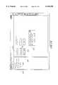
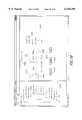
- FIG. 1is a top level block diagram of a server system having a microcontroller network in communication with a local client computer or a remote client computer utilized by one embodiment of the present invention.
- FIG. 2is a detailed block diagram of the microcontroller network shown in FIG. 1.
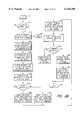
- FIG. 3is a diagram of serial protocol message formats utilized in communications between the client computer and remote interface shown in FIGS. 1 and 2.
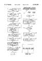
- FIGS. 4a and 4bare one embodiment of a flow diagram of a power-on process performed by the microcontroller network and client computer of FIGS. 1 and 2.
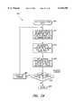
- FIG. 5is one embodiment of a flow diagram of the power-on function shown in FIG. 4b.
- FIGS. 6a and 6bare one embodiment of a flow diagram of a power-off process performed by the microcontroller network and client computer of FIGS. 1 and 2.
- FIG. 7is one embodiment of a flow diagram of the power-off function shown in FIG. 6b.
- FIGS. 8a and 8bare one embodiment of a flow diagram of a reset process performed by the microcontroller network and client computer of FIGS. 1 and 2.
- FIG. 9is one embodiment of a flow diagram of the reset function shown in FIG. 8b.
- FIGS. 10a and 10bare one embodiment of a flow diagram of a display flight recorder process performed by the microcontroller network and client computer of FIGS. 1 and 2.
- FIG. 11is one embodiment of a flow diagram of the read non-volatile RAM (NVRAM) contents function shown in FIG. 10b.
- NVRAMread non-volatile RAM
- FIG. 12a, 12b and 12care a detailed block diagram of the microcontroller network components showing a portion of the inputs and outputs of the microcontrollers shown in FIG. 2.
- FIGS. 13a and 13bare one embodiment of a flow diagram of a system status process performed by the microcontroller network and client computer of FIGS. 1 and 2.
- FIG. 14is one embodiment of a flow diagram of the system status function shown in FIG. 13b.
- FIG. 15is an exemplary screen display of a server power-on window seen at the client computer to control the microcontroller network of FIGS. 1 and 2.
- FIG. 16is an exemplary screen display of a flight recorder window seen at the client computer to control the microcontroller network of FIGS. 1 and 2.
- FIG. 17is an exemplary screen display of a system status window seen at the client computer to control the microcontroller network of FIGS. 1 and 2.
- FIG. 18is an exemplary screen display of a system status:fans window seen at the client computer to control the microcontroller network of FIGS. 1 and 2.
- FIG. 19is an exemplary screen display of a system status:fans:canister A window seen at the client computer to control the microcontroller network of FIGS. 1 and 2.
- the inventive computer server system and client computerincludes a distributed hardware environment management system that is built as a small self-contained network of microcontrollers. Operating independently of the system processor and operating software, the present invention uses one or more separate processors for providing information and managing the hardware environment that may include fans, power supplies and/or temperature.
- One embodiment of the present inventionfacilitates remotely powering-on and powering-off of the server system by use of a client computer.
- the client computermay be local to the server system, or may be at a location remote from the server system, in which case a pair of modems are utilized to provide communication between the client computer and the server system.
- a remote interface boardconnects to the server and interfaces to the server modem.
- Recovery manager softwareis loaded on the client computer to control the power-on and power-off processes and to provide feedback to a user though a graphical user interface.
- Another embodiment of the present inventionfacilitates remotely resetting the server system by use of the client computer.
- Resetting the server systembrings the server and operating system to a normal operating state.
- Recovery manager softwareis loaded on the client computer to control the resetting process and to provide feedback to a user though a graphical user interface.
- Another embodiment of the present inventionprovides for a system log, known as a "flight recorder," which records hardware component failure and software crashes in a Non-Volatile RAM.
- a system logknown as a "flight recorder”
- the system recorderenables system administrators to re-construct system activity by accessing the log. This information is very helpful in diagnosing the server system.
- the system conditionsmay include system log size, presence of faults in the system log, serial number for each of the environmental processors, serial numbers for each power supply of the system, system identification, system log count, power settings and presence, canister presence, temperature, BUS/CORE speed ratio, fan speeds, setting for fan faults, LCD display, Non-Maskable Interrupt (NMI) request bits, CPU fault summary, FRU status, JTAG enable bit, system log information, remote access password, over-temperature fault, CPU error bits, CPU presence, CPU thermal fault bits, and remote port modem.
- NMINon-Maskable Interrupt
- the server system and client computerprovides mechanisms for the evaluation of the data that the system collects and methods for the diagnosis and repair of server problems in a manner that system errors can be effectively and efficiently managed. The time to evaluate and repair problems is minimized.
- the server systemensures that the system will not go down, so long as sufficient system resources are available to continue operation, but rather degrade gracefully until the faulty components can be replaced.
- the server system hardware environment 100may be built around a self-contained network of microcontrollers, such as, for example, a remote interface microcontroller on the remote interface board or circuit 104, a system interface microcontroller 106 and a system recorder microcontroller 110.
- This distributed service processor network 102may operate as a fully self-contained subsystem within the server system 100, continuously monitoring and managing the physical environment of the machine (e.g., temperature, voltages, fan status).
- the microcontroller network 102continues to operate and provides a system administrator with critical system information, regardless of the operational status of the server 100.
- Information collected and analyzed by the microcontroller network 102can be presented to a system administrator using either SNMP-based system management software (not shown), or using microcontroller network Recovery Manager software 130 through a local connection 121 or a dial-in connection 123.
- the system management softwarewhich interfaces with the operating software (OS) 108 such as Microsoft Windows NT Version 4.0 or Novell Netware Version 4.11, for example, provides the ability to manage the specific characteristics of the server system, including Hot Peripheral Component Interconnect (PCI), power and cooling status, as well as the ability to handle alerts associated with these features when the server is operational.
- OSoperating software
- PCIHot Peripheral Component Interconnect
- the microcontroller network Recovery Manager software 130allows the system administrator to query the status of the server system 100 through the microcontroller network 102, even when the server is down.
- the server Operating Software 108does not need to be running to utilize the Recovery Manager 130. Users of the Recovery Manager 130 are able to manage, diagnose and restore service to the server system quickly in the event of a failure through a friendly graphical user interface (GUI).
- GUIgraphical user interface
- a system administratorcan use the Recovery Manager 130 to re-start a failed system through a modem connection 123.
- the administratorcan remotely view the microcontroller network Flight Recorder, a feature that may, in one embodiment, store all system messages, status and error reports in a circular System Recorder memory.
- the System Recorder memorymay be a Non-Volatile Random Access Memory buffer (NVRAM) 112.
- NVRAMNon-Volatile Random Access Memory buffer
- the remote interface or remote interface board (RIB) 104interfaces the server system 100 to an external client computer.
- the RIB 104connects to either a local client computer 122 at the same location as the server 100 or to a remote client computer 124 either directly or through an optional switch 120.
- the client computer 122/124may in one embodiment run either Microsoft Windows 95 or Windows NT Workstation version 4.0 operating software (OS) 132.
- the processor and RAM requirements of the client computer 122/124are such as may be specified by the vendor of the OS 132.
- the serial port of the client computer 122/124may utilize a type 16550A Universal Asynchronous Receiver Transmitter (UART).
- UARTUniversal Asynchronous Receiver Transmitter
- the switchfacilitates either the local connection 121 or the modern connection 123 at any one time, but allows both types of connections to be connected to the switch.
- either the local connection 121 or the modem connection 123is connected directly to the RIB 104.
- the local connection 121utilizes a readily available null-modem serial cable to connect to the local client computer.
- the modem connectionmay utilize a Hayes-compatible server modem 126 and a Hayes-compatible client modem 128.
- a model fax modem V.34 X 33.6 K available from Zoomis utilized as the client modem and the server modem.
- a Sportster 33.6 K fax modem available from US Roboticsis utilized as the client modem.
- the remote interface 104has a serial port connector (not shown) that directly connects with a counterpart serial port connector of the external server modem 126 without the use of a cable. If desired, a serial cable could be used to interconnect the remote interface 104 and the server modem 126.
- the cable end of an AC to DC power adapter(not shown, for example 120 Volt AC/7.5 Volt DC) is then connected to a DC power connector (not shown) of the remote interface, while the double-prong end is plugged into a 120 Volt AC wall outlet.
- RJ-45 parallel-wire data cable 103is then plugged into an RJ-45 jack (not shown) on the remote interface 104, while the other end is plugged into a RJ-45 Recovery Manager jack on the server 100.
- the RJ-45 jack on the serverthen connects to the microcontroller network 102.
- the server modem 126is then connected to a communications network 127 using an appropriate connector.
- the communications network 127may be a public switched telephone network, although other modem types and communication networks are envisioned.
- the communications networkcan be a cable television network.
- satellite modulator/demodulatorscan be used in conjunction with a satellite network.
- the server modem to client modem connectionmay be implemented by an Internet connection utilizing the well known TCP/IP protocol. Any of several Internet access devices, such as modems or network interface cards, may be utilized.
- the communications network 127may utilize either circuit or packet switching.
- a serial cablefor example, a 25-pin D-shell
- the client modem 128is then connected to the communications network 127 using an appropriate connector.
- Each modemis then plugged into an appropriate power source for the modem, such as an AC outlet.
- the Recovery Manager software 130is loaded into the client computer 124, if not already present, and activated.
- the steps of connecting the local client computer 122 to the server 100are similar, but modems are not necessary.
- the main differenceis that the serial port connector of the remote interface 104 connects to a serial port of the local client computer 122 by the null-modem serial cable 121.
- the current inventionmay include a network of microcontrollers 102 (FIG. 1).
- the microcontrollersmay provide functionality for system control, diagnostic routines, self-maintenance control, and event logging processors.
- a further description of the microcontrollers and microcontroller networkis provided in U.S. patent application Ser. No. 08/942,402, entitled "Diagnostic and Managing Distributed Processor System".
- the network of microcontrollers 102includes ten processors.
- One of the purposes of the microcontroller network 102is to transfer messages to the other components of the server system 100.
- the may processorsinclude: a System Interface controller 106, a CPU A controller 166, a CPU B controller 168, a System Recorder 110, a Chassis controller 170, a Canister A controller 172, a Canister B controller 174, a Canister C controller 176, a Canister D controller 178 and a Remote Interface controller 200.
- the Remote Interface controller 200is located on the RIB 104 (FIG. 1) which is part of the server system 100, but may be external to a server enclosure.
- the System Interface controller 106, the CPU A controller 166 and the CPU B controller 168are located on a system board 150 (also sometimes called a motherboard) in the server 100. Also located on the system board are one or more central processing units (CPUs) or microprocessors 164 and an Industry Standard Architecture (ISA) bus 162 that connects to the System Interface Controller 106. Of course, other buses such as PCI, EISA and Microchannel may be used.
- CPUscentral processing units
- ISAIndustry Standard Architecture
- the CPU 164may be any conventional general purpose single-chip or multi-chip microprocessor such as a Pentium®, Pentium® Pro or Pentium® II processor available from Intel Corporation, a SPARC processor available from Sun Microsystems, a MIPS® processor available from Silicon Graphics, Inc., a Power PC® processor available from Motorola, or an ALPHA® processor available from Digital Equipment Corporation.
- the CPU 164may be any conventional special purpose microprocessor such as a digital signal processor or a graphics processor.
- the System Recorder 110 and Chassis controller 170may be located on a backplane 152 of the server 100.
- the System Recorder 110 and Chassis controller 170are the first microcontrollers to power up when server power is applied.
- the System Recorder 110, the Chassis controller 170 and the Remote Interface microcontroller 200(on the RIB) are the three microcontrollers that have a bias 5 Volt power supplied to them. If main server power is off, an independent power supply source for the bias 5 Volt power is provided by the RIB 104 (FIG. 1).
- the Canister controllers 172-178are not considered to be part of the backplane 152 because they are located on separate cards which are removable from the backplane 152.
- Each of the microcontrollershas a unique system identifier or address.
- the addressesare as follows in Table 1:
- the microcontrollersmay be Microchip Technologies, Inc. PIC processors in one embodiment, although other microcontrollers, such as an 8051 available from Intel, an 8751, available from Atmel, or a P80CL580 microprocessor available from Philips Semiconductor, could be utilized.
- the PIC16C74 (Chassis controller 170) and PIC16C65 (the other controllers)are members of the PIC16CXX family of high-performance CMOS, fully-static, EPROM-based 8-bit microcontrollers.
- the PIC controllershave 192 bytes of RAM, in addition to program memory, three timer/counters, two capture/compare/Pulse Width Modulation modules and two serial ports.
- the synchronous serial portis configured as a two-wire Inter-Integrated Circuit (I 2 C) bus in one embodiment of the invention.
- the PIC controllersuse a Harvard architecture in which program and data are accessed from separate memories. This improves bandwidth over traditional von Neumann architecture controllers where program and data are fetched from the same memory. Separating program and data memory further allows instructions to be sized differently than the 8-bit wide data word. Instruction opcodes are 14-bit wide making it possible to have all single word instructions. A 14-bit wide program memory access bus fetches a 14-bit instruction in a single cycle.
- the microcontrollerscommunicate through an I 2 C serial bus, also referred to as a microcontroller bus 160.
- the document "The I 2 C Bus and How to Use It” (Philips Semiconductor, 1992)is hereby incorporated by reference.
- the I 2 C busis a bidirectional two-wire bus and operates at a 400 kbps rate in the present embodiment.
- other bus structures and protocolscould be employed in connection with this invention.
- the Apple Computer ADB, Universal Serial Bus, IEEE-1394 (Firewire), IEEE-488 (GPIB), RS-485, or Controller Area Network (CAN)could be utilized as the microcontroller bus.
- Control on the microcontroller busis distributed.
- Each microcontrollercan be a sender (a master) or a receiver (a slave) and each is interconnected by this bus.
- a microcontrollerdirectly controls its own resources, and indirectly controls resources of other microcontrollers on the bus.
- serial data lineSDA
- serial clock lineSCL
- Each device connected to the busis software addressable by a unique address and simple master/slave relationships exist at all times; masters can operate as master-transmitters or as master-receivers.
- the busis a true multi-master bus including collision detection and arbitration to prevent data corruption if two or more masters simultaneously initiate data transfer.
- Serial, 8-bit oriented, bidirectional data transferscan be made at up to 400 kbit/second in the fast mode.
- serial dataSDA
- serial clockSCL
- Each deviceis recognized by a unique address and can operate as either a transmitter or receiver, depending on the function of the device.
- a memory device connected to the I 2 C buscould both receive and transmit data.
- devicescan also be considered as masters or slaves when performing data transfers (see Table 2).
- a masteris the device which initiates a data transfer on the bus and generates the clock signals to permit that transfer. At that time, any device addressed is considered a slave.
- the I 2 C-busis a multi-master bus. This means that more than one device capable of controlling the bus can be connected to it.
- mastersare usually microcontrollers, consider the case of a data transfer between two microcontrollers connected to the I 2 C-bus. This highlights the master-slave and receiver-transmitter relationships to be found on the I 2 C-bus. It should be noted that these relationships are not permanent, but depend on the direction of data transfer at that time. The transfer of data would proceed as follows:
- microcontroller Awants to send information to microcontroller B:
- microcontroller Amaster
- microcontroller Bslave
- microcontroller Amaster-transmitter
- microcontroller Bslave-receiver
- microcontroller Aterminates the transfer.
- microcontroller Awants to receive information from microcontroller B:
- microcontroller Amaster addresses microcontroller B (slave);
- microcontroller Amaster-receiver
- microcontroller Bslave-transmitter
- microcontroller Aterminates the transfer.
- the master(microcontroller A) generates the timing and terminates the transfer.
- the clock signals during arbitrationare a synchronized combination of the clocks generated by the masters using the wired-AND connection to the SCL line.
- Each master microcontrollergenerates its own clock signals when transferring data on the bus.
- the command, diagnostic, monitoring and history functions of the microcontroller network 102are accessed using a global network memory model in one embodiment. That is, any function may be queried simply by generating a network "read" request targeted at the function's known global network address. In the same fashion, a function may be exercised simply by "writing" to its global network address. Any microcontroller may initiate read/write activity by sending a message on the I 2 C bus to the microcontroller responsible for the function (which can be determined from the known global address of the function).
- the network memory modelincludes typing information as part of the memory addressing information.
- Using a network global memory model in one embodimentplaces relatively modest requirements for the I 2 C message protocol.
- All messagesconform to the I 2 C message format including addressing and read/write indication.
- Any controllercan originate (be a Master) or respond (be a Slave).
- All message transactionsconsist of I 2 C "Combined format" messages. This is made up of two back-to-back I 2 C simple messages with a repeated START condition between (which does not allow for re-arbitrating the bus). The first message is a Write (Master to Slave) and the second message is a Read (Slave to Master).
- Sub-Addressing formatsvary depending on data type being used.
- the microcontroller network remote interface serial protocolcommunicates microcontroller network messages across a point-to-point serial link. This link is between the RIB controller 200 that is in communication with the Recovery Manager 130 at the remote client 122/124. This protocol encapsulates microcontroller network messages in a transmission packet to provide error-free communication and link security.
- the remote interface serial protocoluses the concept of byte stuffing. This means that certain byte values in the data stream have a particular meaning. If that byte value is transmitted by the underlying application as data, it must be transmitted as a two-byte sequence.
- a two-byte sequencemust be substituted for that byte.
- the sequenceis a byte with the value of SUB, followed by a type with the value of the original byte, which is incremented by one. For example, if a SUB byte occurs in a message, it is transmitted as a SUB followed by a byte that has a value of SUB+1.
- Requests 202which are sent by remote management (client) computers 122/124 (FIG. 1) to the remote interface 104.
- the microcontroller network 102(FIG. 1) performs various system administration tasks, such as, for example, monitoring the signals that come from server control switches, temperature sensors and client computers. By such signals, the microcontroller network 102, for example, turns on or turns off power to the server components, resets the server system, turns the system cooling fans to high, low or off, provides system operating parameters to the Basic Input/Output System (BIOS), transfers power-on self test (POST) events information from the BIOS, and/or sends data to a system display panel and remote computers.
- BIOSBasic Input/Output System
- POSTpower-on self test
- a microcontrollersuch as the remote interface microcontroller 200, handles two primary tasks: Sending and Receiving messages.
- Incoming messagesare handled based on interrupt, where a first byte of an incoming message is the Slave Address which is checked by all controllers connected to the microcontroller bus 160 (FIG. 2). Whichever microcontroller has the matched ID would respond with an acknowledgement to the sender controller.
- the senderthen sends one byte of the message type followed by a two byte command ID, low byte first.
- the next byte of the messagedefines the length of the data associated with the message.
- the first byte of the messagealso specifies whether it is a WRITE or READ command. If it is a WRITE command, the slave controller executes the command with the data provided in the message and sends back a status response at the end of the task. If it is a READ command, the slave controller gathers the requested information and sends it back as the response.
- the codes to execute request commandsare classified in groups according to the data type to simplify the code.
- Messagescan be initiated by any controller on the bus 160 (FIG. 2).
- the messagecan be an event detected by a controller and sent to the System Recorder controller and System Interface controller 106, or it could also be a message from the remote interface 104 (FIG. 1) to a specific controller on the bus 160.
- the senderusually sends the first byte defining the target processor and waits for the acknowledgement, which is the reverse logic from the Receiving a Message sequence.
- the senderalso generates the necessary clock for the communication.
- Process 270begins at start state 272 and if a connection between the client computer 122/124 and the server 100 is already active, process 270 proceeds to directly to state 296. Otherwise, if a connection is not already active, process 270 proceeds to state 273 and utilizes the Recovery Manager software 130 to present a dialog window to the user on a display of the client computer 122/124 requesting information. The user is requested to enter a password for security purposes.
- the dialog windowalso has a pair of radio-buttons to select either a serial (local) connection or a modem (remote) connection. If serial is selected, the user is requested to select a COM port. If modem is selected, the user is requested to enter a telephone number to be used in dialing the server modem.
- process 270determines if a modem-type connection was selected.
- a modem-type connectionis generally utilized in the situation where the client computer 124 is located at a location remote from the server 100. If it is determined at decision state 274 that a modem connection is utilized, process 270 moves to state 276 wherein the client computer 124 is connected to the client modem 128. Moving to state 278, a connection is established between the client modem 128 and the server modem 126 via a communications network 127, as previously described above. Continuing at state 280, the server modem 126 connects with the remote interface 104. Proceeding to state 282, the remote interface 104 connects to the server 100 via the RJ-45 cable 103.
- the Recovery Manager software 130 at the client computer 124dials the server modem 126 through the client modem 128, handshakes with the remote interface 104, and checks the previously entered password.
- Process 270remains at state 286 until a successful communication path with the remote interface 104 is established.
- process 270proceeds to state 288 wherein the local client computer 122 is connected with the remote interface 104.
- the remote interface 104is connected with the server 100.
- the previously entered password(at state 273) is sent to the remote interface 104 to identify the user at the local computer 122. If the password matches a password that is stored in the server system 100, the communication path with the remote interface is enabled.
- the Recovery Manager software 130will in one embodiment display a recovery manager window 920, which includes a server icon 922 as shown in FIG. 15.
- a server window panel 928 and a confirmation dialog box 936are not displayed at this time.
- the user at the client computer 122/124selects the server icon on the display, such as, for example by clicking a pointer device on the icon.
- the server window panel 928is then displayed to the user.
- the user confirmation box 936is not displayed at this time.
- the Recovery Manager software 130 at the client computer 122/124provides a microcontroller network command (based on selecting the Power On button) and sends it to communication layer software. Proceeding to state 306, the communication layer puts a communications protocol around the command (from state 304) and sends the encapsulated command to the server through the client modem 128, the server modem 126 and the remote interface 104.
- the communications protocolwas discussed in conjunction with FIG. 3 above.
- the encapsulated commandis of the Request type 202 shown in FIG. 3.
- the remote interface 104converts the encapsulated command to the microcontroller network format, which is described in U.S.
- Process 270then continues to a function 310 wherein the server receives the command and powers on the server. Function 310 will be further described in conjunction with FIG. 5.
- the response generated by the serveris then sent to the remote interface 104.
- the microcontroller(the Chassis controller 170 in this instance) performing the command at the server returns status at the time of initiation of communication with the microcontroller.
- the Recovery Manager 130sends a read status command to the Chassis controller (using states 304 and 306) to retrieve information on the results of the operation.
- process 270determines if the power on command was successful. If so, process 270 proceeds to state 316 wherein the remote interface 104 sends the response to the server modem 126 indicating the success of the command. Alternatively, if a local connection 121 is utilized, the response is sent to the local client computer 122. However, if the power on is not successful, as determined at decision state 314, process 270 proceeds to state 318 wherein the remote interface 104 sends the response to the server modem (or local client computer) indicating a failure of the command. At the conclusion of either state 316 or 318, process 270 proceeds to state 320 wherein the remote interface 104 sends the response back through the server modem 126 to the client modem 128.
- state 322the client modem 128 sends the response back to the Recovery Manager software 130 at the remote client computer 124. Note that if the local connection 121 is being utilized, states 320 and 322 are not necessary. Proceeding to decision state 324, process 270 determines whether the command was successful. If so, process 270 continues at state 326 and displays a result window showing the success of the command on the display at the client computer 122/124. However, if the command was not successful, process 270 proceeds to state 328 wherein a result window showing failure of the command is displayed to the user. Moving to state 330, the details of the command information are available, if the user so desires, by selecting a details button. At the completion of state 326 or state 330, process 270 completes at end state 332.
- function 310proceeds to state 362 and logs the requested power-on to the server 100 in the System Recorder memory 112. Proceeding to decision state 364, function 310 determines if a system over-temperature condition is set. If so, function 310 proceeds to state 366 and sends a over-temperature message to the remote interface 104. Advancing to state 368, because the system over-temperature condition is set, the power-on process is stopped and function 310 returns at a return state 370.
- function 310proceeds to state 372 and sets an internal power-on indicator and a reset/run countdown timer.
- the reset/run countdown timeris set to a value of five.
- function 310turns on the power and cooling fans for the server system board 150, backplane 152 and I/O canisters.
- the microcontroller networkholds the main system processor reset/run control line in the reset state until the reset/run countdown timer expires to allow the system power to stabilize.
- BIOS Power-On Self TestPOST
- BIOSinitializes a PCI-ISA bridge and a microcontroller network driver.
- the microcontroller network softwaremonitors: hardware temperatures, switches on a control panel on the server, and signals from the remote interface 104.
- state 380may be performed anywhere during states 376 to 394 because the BIOS operations are performed by the server CPUs 164 (FIG. 2) independently of the microcontroller network 102.
- Function 310then moves to a BIOS POST Coldstart function 386.
- BIOS subroutinesIn the Coldstart POST function, approximately 61 BIOS subroutines are called.
- the major groups of the Coldstart pathinclude: CPU initialization, DMA/timer reset, BIOS image check, chipset initialization, CPU register initialization, CMOS test, PCI initialization, extended memory check, cache enable, and message display.
- BIOS POST Coldstart function 386function 310 proceeds to state 388 where BIOS POST events are logged in the System Recorder memory 112. Proceeding to state 390, the BIOS POST performs server port initialization. Continuing at state 392, the BIOS POST initializes the Operating System related controllers (e.g., floppy controller, hard disk controller) and builds a multi-processor table. Advancing to state 394, the BIOS POST performs an OS boot preparation sequence. Function 310 ends at a return state 398.
- Operating System related controllerse.g., floppy controller, hard disk controller
- Process 420begins at start state 422 and if a connection between the client computer 122/124 and the server 100 is already active, process 420 proceeds to directly to state 446. Otherwise, if a connection is not already active, process 420 proceeds to state 423 and utilizes the Recovery Manager software 130 to present a dialog window to the user on a display of the client computer 122/124 requesting information. The user is requested to enter a password for security purposes.
- the dialog windowalso has a pair of radio-buttons to select either a serial (local) connection or a modem (remote) connection. If serial is selected, the user is requested to select a COM port. If modem is selected, the user is requested to enter a telephone number to be used in dialing the server modem.
- process 420determines if the modem-type connection 123 will be utilized.
- the modem-type connectionis generally utilized in the situation where the client computer 124 is located at a location remote from the server 100. If it is determined at decision state 424 that a modem connection is utilized, process 420 moves to state 426 wherein the client computer 124 is connected to the client modem 128. Moving to state 428, a connection is established between the client modem 128 and the server modem 126 via the communications network 127. Continuing at state 430, the server modem 126 connects with the remote interface 104. Proceeding to state 432, the remote interface 104 connects to the server 100 via the RJ-45 cable 103.
- the Recovery Manager software 130 at the client computer 124dials the server modem 126 through the client modem 128, handshakes with the remote interface 104, and checks the previously entered password.
- Process 420remains at state 436 until a successful communication path with the remote interface 104 is established.
- process 420proceeds to state 438 wherein the local client computer 122 is connected with the remote interface 104.
- the remote interface 104is connected with the server 100.
- the previously entered password(at state 423) is sent to the remote interface 104 to identify the user at the local computer 122. If the password matches the password that is stored in the server system 100, the communication path with the remote interface 104 is enabled.
- process 420continues at state 446.
- the Recovery Manager software 130will in one embodiment display the Recovery Manager window 920, which includes the server icon 922 as shown in FIG. 15.
- the server window panel 928 and the confirmation dialog box 936are not displayed at this time.
- the user at the client computer 122/124selects the server icon 922 on the display, such as by clicking the pointer device on the icon.
- the server window panel 928(FIG. 15) is then displayed to the user.
- the userselects a Power Off button 932 on the window panel 928 to trigger the power-off operation.
- a user confirmation dialog boxis then displayed on the client computer display. If the user confirms that the server is to be powered down, process 420 proceeds through off page connector A 452 to state 454 on FIG. 6b.
- the Recovery Manager software 130 at the client computer 122/124provides a microcontroller network command (based on selecting the Power Off button) and sends it to communication layer software. Proceeding to state 456, the communication layer puts a communications protocol around the command (from state 454) and sends the encapsulated command to the server through the client modem 128, the server modem 126 and the remote interface 104.
- the encapsulated commandis of the Request type 202 shown in FIG. 3.
- Process 420then continues to a function 460 wherein the server receives the command and powers off the server. Function 460 will be further described in conjunction with FIG. 7.
- the response generated by the serveris then sent to the remote interface 104.
- the microcontroller(the Chassis controller 170 in this instance) performing the command at the server returns status at the time of initiation of communication with the microcontroller.
- the Recovery Manager 130sends a read status command to the Chassis controller (using states 454 and 456) to retrieve information on the results of the operation.
- process 420determines if the power off command was successful. If so, process 420 proceeds to state 466 wherein the remote interface 104 sends the response to the server modem 126 indicating the success of the command. Alternatively, if a local connection 121 is utilized, the response is sent to the local client computer 122. However, if the power off is not successful, as determined at decision state 464, process 270 proceeds to state 468 wherein the remote interface 104 sends the response to the server modem (or local client computer) indicating a failure of the command. At the conclusion of either state 466 or 468, process 420 proceeds to state 470 wherein the remote interface 104 sends the response back through the server modem 126 to the client modem 128.
- state 472the client modem 128 sends the response back to the Recovery Manager software 130 at the remote client computer 124. Note that if the local connection 121 is being utilized, states 470 and 472 are not necessary. Proceeding to decision state 474, process 420 determines whether the command was successful. If so, process 420 continues at state 476 and displays a result window showing the success of the command on the display at the client computer 122/124. However, if the command was not successful, process 420 proceeds to state 478 wherein a result window showing failure of the command is displayed to the user. Moving to state 480, the details of the command information are available, if the user so desires, by selecting a details button. At the completion of state 476 or state 480, process 420 completes at end state 482.
- function 460proceeds to state 502 and logs the requested Power-Off message in the System Recorder memory 112 (FIG. 2) by use of the System Recorder controller 110.
- function 460clears a system run indicator and clears the reset/run countdown timer.
- function 460clears an internal power-on indicator. In one embodiment, the power-on indicator is stored by a variable "S4 -- power -- on”.
- Function 460utilizes the CPU A controller 166 for state 504 and the Chassis controller 170 for state 506.
- function 460turns off the power and the cooling fans for the system board 150, the backplane 152 and the canister(s) associated with the Canister controllers 172-178. Function 460 ends at a return state 512.
- Process 540begins at start state 542 and if a connection between the client computer 122/124 and the server 100 is already active, process 540 proceeds to directly to state 566. Otherwise, if a connection is not already active, process 540 proceeds to state 543 and utilizes the Recovery Manager software 130 to present a dialog window to the user on a display of the client computer 122/124 requesting information. The user is requested to enter a password for security purposes.
- the dialog windowalso has a pair of radio-buttons to select either a serial (local) connection or a modem (remote) connection. If serial is selected, the user is requested to select a COM port. If modem is selected, the user is requested to enter a telephone number to be used in dialing the server modem.
- process 540determines if the modem-type connection 123 was selected.
- the modem-type connectionis generally utilized in the situation where the client computer 124 is located at a location remote from the server 100. If it is determined at decision state 544 that a modem connection is utilized, process 540 moves to state 546 wherein the client computer 124 is connected to the client modem 128. Moving to state 548, a connection is established between the client modem 128 and the server modem 126 via the communications network 127. Continuing at state 550, the server modem 126 connects with the remote interface 104. Proceeding to state 552, the remote interface 104 connects to the server 100 via the RJ-45 cable 103.
- the Recovery Manager software 130 at the client computer 124dials the server modem 126 through the client modem 128, handshakes with the remote interface 104, and checks the previously entered password.
- Process 540remains at state 556 until a successful communication path with the remote interface 104 is established.
- process 540proceeds to state 558 wherein the local client computer 122 is connected with the remote interface 104.
- the remote interface 104is connected with the server 100.
- the password previously enteredis sent to the remote interface 104 to identify the user at the local computer 122. If the password matches the password that is stored in the server system 100, the communication path with the remote interface 104 is enabled.
- process 540continues at state 566.
- the Recovery Manager software 130will in one embodiment display the Recovery Manager window 920, which includes the server icon 922 as shown in FIG. 15.
- the server window panel 928 and the confirmation dialog box 936are not displayed at this time.
- the user at the client computer 122/124selects the server icon 922 on the display, such as by clicking the pointer device on the icon.
- the server window panel 928(FIG. 15) is then displayed to the user.
- the user confirmation box 936is not displayed at this time.
- a System Reset button 934 on the window panel 928to trigger the System Reset operation.
- a user confirmation dialog boxis then displayed on the client computer display. If the user confirms that the system is to be reset, process 540 proceeds through off page connector A 572 to decision state 574 on FIG. 8b.
- process 540determines if the server is currently running (powered up, such as after a power on command has been issued). If not, process 540 continues to state 576 wherein a warning message that the server must be running to execute a system reset is displayed on the client computer display to the user. After the warning has been displayed, process 540 moves to end state 578 to terminate the reset process. However, if the server is running, as determined at decision state 574, process 540 proceeds to state 580.
- the Recovery Manager software 130 at the client computer 122/124provides a microcontroller network command (based on selecting the System Reset button) and sends it to the communication layer software. Proceeding to state 582, the communication layer puts a communications protocol around the command (from state 580) and sends the encapsulated command to the server through the client modem 128, the server modem 126 and the remote interface 104.
- the encapsulated commandis of the Request type 202 shown in FIG. 3.
- Process 540then continues to a function 590 wherein the server receives the command and resets the server. Function 590 will be further described in conjunction with FIG. 9.
- the response generated by the serveris then sent to the remote interface 104.
- the microcontroller(the CPU A controller 166 in this instance) performing the command at the server returns status at the time of initiation of communication with the microcontroller.
- the Recovery Manager 130sends a read status command to the CPU A controller (using states 580 and 582) to retrieve information on the results of the operation.
- process 540determines if the system reset command was successful. If so, process 540 proceeds to state 596 wherein the remote interface 104 sends the response to the server modem 126 indicating the success of the command. Alternatively, if a local connection 121 is utilized, the response is sent to the local client computer 122. However, if the system reset is not successful, as determined at decision state 594, process 540 proceeds to state 598 wherein the remote interface 104 sends the response to the server modem (or local client computer) indicating a failure of the command. At the conclusion of either state 596 or 598, process 540 proceeds to state 600 wherein the remote interface 104 sends the response back through the server modem 126 to the client modem 128.
- state 602the client modem 128 sends the response back to the Recovery Manager software 130 at the remote client computer 124. Note that if the local connection 121 is being utilized, states 600 and 602 are not necessary. Proceeding to decision state 604, process 540 determines whether the command was successful. If so, process 540 continues at state 606 and displays a result window showing the success of the command on the display at the client computer 122/124. However, if the command was not successful, process 540 proceeds to state 608 wherein a result window showing failure of the command is displayed to the user. Moving to state 610, the details of the command information are available, if the user so desires, by selecting a details button. At the completion of state 606 or state 610, process 540 completes at end state 612.
- BIOS POST Warmstart function 384In the Warmstart function 384, approximately 41 subroutines are called. These include the general operations of: reset flag, DMA/timer reset, chipset initialization, CMOS test, PCI initialization, cache enable, and message display.
- BIOS POST Warmstart function 384function 590 proceeds to state 388 where BIOS POST events are logged in the System Recorder memory 112. Proceeding to state 390, the BIOS POST performs server port initialization.
- the BIOS POSTinitializes the Operating System related controllers (e.g., floppy disk controller, hard disk controller) and builds a multi-processor table. Advancing to state 394, the BIOS POST performs an OS boot preparation sequence. Moving to state 632, the BIOS initiates an OS boot sequence to bring the operating software to an operational state. Function 590 ends at a return state 636.
- the Operating System related controllerse.g., floppy disk controller, hard disk controller
- a Flight Recorderwhich includes the System Recorder controller 110 and the System Recorder memory 112, provides a subsystem for recording a time-stamped history of events leading up to a failure in server system 100.
- the System Recorder memory 112may also store identification of components of the server system.
- the System Recorder 110is the only controller which does not initiate messages to other controllers.
- the System Recorder 110receives event log information from other controllers and stores the data into the System Recorder memory 112. Upon request, the System Recorder 110 can send a portion and/or the entire logged data to a requesting controller.
- the System Recorder 110puts a time stamp from a real-time clock with the data that is saved.
- Process 670begins at start state 672 and if a connection between the client computer 122/124 and the server 100 is already active, process 670 proceeds to directly to state 696. Otherwise, if a connection is not already active, process 670 proceeds to state 673 and utilizes the Recovery Manager software 130 to present a dialog window to the user on a display of the client computer 122/124 requesting information. The user is requested to enter a password for security purposes.
- the dialog windowalso has a pair of radio-buttons to select either a serial (local) connection or a modem (remote) connection. If serial is selected, the user is requested to select a COM port. If modem is selected, the user is requested to enter a telephone number to be used in dialing the server modem.
- process 670determines if the modem-type connection 123 was selected.
- the modem-type connectionis generally utilized in the situation where the client computer 124 is located at a location remote from the server 100. If it is determined at decision state 674 that a modem connection is utilized, process 670 moves to state 676 wherein the client computer 124 is connected to the client modem 128. Moving to state 678, a connection is established between the client modem 128 and the server modem 126 via the communications network 127. Continuing at state 680, the server modem 126 connects with the remote interface 104. Proceeding to state 682, the remote interface 104 connects to the server 100 via the RJ-45 cable 103.
- the Recovery Manager software 130 at the client computer 124dials the server modem 126 through the client modem 128, handshakes with the remote interface 104, and checks the previously entered password.
- Process 670remains at state 686 until a successful communication path with the remote interface 104 is established.
- process 670proceeds to state 688 wherein the local client computer 122 is connected with the remote interface 104.
- the remote interface 104is connected with the server 100.
- the previously entered password(at state 673) is sent to the remote interface 104 to identify the user at the local computer 122. If the password matches the password that is stored in the server system 100, the communication path with the remote interface 104 is enabled.
- process 670continues at state 696.
- the Recovery Manager software 130will in one embodiment display a Recovery Manager window 940, which includes a Flight Recorder icon 942 as shown in FIG. 16.
- a Flight Recorder window panel 944is not displayed at this time.
- the user at the client computer 122/124selects the Flight Recorder icon 942 on the display, such as by clicking the pointer device on the icon.
- the Flight Recorder window panel 944(FIG. 16) is then displayed to the user.
- the userselects a Download button 954 on the window panel 944 to trigger the display of the Flight Recorder operation.
- Flight Recorder window panel 944includes a Save button 956 for saving a downloaded Flight Recorder (system log or System Recorder memory 112, FIG. 1) and a Print button 958 for printing the downloaded Flight Recorder.
- a user confirmation dialog box(not shown) is then displayed on the client computer display showing a number of messages in the server system log.
- process 670displays a progress window of downloaded messages. Process 670 proceeds through off page connector A 703 to state 704 on FIG. 10b.
- the Recovery Manager software 130 at the client computer 122/124provides a microcontroller network command (based on selecting the Download Flight Recorder button 954) and sends it to the communication layer software. Proceeding to state 706, the communication layer puts a communications protocol around the command (from state 704) and sends the encapsulated command to the server through the client modem 128, the server modem 126 and the remote interface 104.
- the encapsulated commandis of the Request type 202 shown in FIG. 3.
- Process 670then continues to a function 710 wherein the server receives the command and reads the contents of the System Recorder memory 112 (FIG. 1). In one embodiment, each read request generates one response such that the Recovery Manager 130 generates multiple read requests to read the complete system log. The server generates one log response during function 710. Function 710 will be further described in conjunction with FIG. 11.
- each of the responses generated by the serverare then sent one at a time to the remote interface 104.
- Process 670then proceeds to state 714 wherein the remote interface 104 sends each response back through the server modem 126 to the client modem 128.
- each responseis sent directly to the local client computer 122.
- the client modem 128sends the response back to the Recovery Manager software 130 at the remote client computer 124. Note that if the local connection 121 is being utilized, state 716 is not necessary. Proceeding to decision state 718, process 670 determines whether the entire download of the Flight Recorder was successful by checking for an end of system log messages status.
- process 670continues at state 720 wherein the Recovery Manager 130 (FIG. 1) displays (and optionally stores) all messages in the Flight Recorder window panel 944 on the display at the client computer 122/124. However, if the entire download was not successful, process 670 proceeds to state 722 wherein the Recovery Manager 130 displays (and optionally stores) all messages that were received by the Recovery Manager 120 in the Flight Recorder window panel 944. At the completion of state 720 or state 722, process 670 completes at end state 724.
- the Flight Recorder window panel 944includes four fields: Time Stamp 946, Severity 948, Message Source 950, and Message 952.
- Each message in the system log 112includes a time stamp 946 of when the item was written to the log 112.
- the time stampincludes the date and the local time zone of the client computer 122/124 running the Recovery Manager 130.
- the time stamp informationis generated by a timer chip 760 (FIG. 12a).
- the Severity field 948includes a severity value selected from: unknown, informational, warning, error, and severe/fatal.
- the Message Source field 950includes a source selected from: microcontroller network internal, onboard diagnostics, external diagnostics, BIOS, time synchronizer, Windows®, WindowsNT®, NetWare, OS/2, UNIX, and VAX/VMS.
- the messages in the Message field 952correspond to the data returned by the controllers on the microcontroller network 102.
- the controller message datais used to access a set of Message tables associated with the Recovery Manager 130 on the client computer 122/124 to generate the information displayed in the Message field 952.
- the Message tablesinclude a microcontroller network (wire services) table, a BIOS table and a diagnostics table.
- An exemplary message from the microcontroller network tableincludes "temperature sensor #5 exceeds warning threshold".
- An exemplary message from the BIOS tableincludes "check video configuration against CMOS”.
- An exemplary message from the diagnostics tableincludes "correctable memory error”.
- the Read NVRAM Contents function 710will now be described. Beginning at start state 740, function 710 proceeds to state 742 and loads a block log pointer.
- the System Recorder memory or NVRAM 112(FIG. 2) has two 64 K byte memory blocks.
- the first blockis a memory block which stores ID codes of the devices installed in the network. Hence, a command addressed to the first block is typically generated by a controller responsible for updating the presence or absence of devices in the network.
- the second block of the memory 112is a memory block that stores event messages in connection with events occurring in the network. Hence, controllers addressing the second block do so to add entries to the system log or to read previous entries contained in the system log.
- the System Recorderuses log address pointers to determine where the next new entry in the log should be placed and also to determine where the log is currently being read from.
- a further description of the System Recorder 110 and the NVRAM 112is provided in U.S. patent application Ser. No. 08/942,381, entitled, "BLACK BOX RECORDER FOR INFORMATION SYSTEM EVENTS".
- function 710reads the log message as addressed by the log pointer. Proceeding to state 746, function 710 returns the log message to the requestor on the microcontroller bus 160 (FIG. 2), which is the remote interface controller 200 in this situation. In one embodiment, the remote interface 104 stores the message in a memory 762 (FIG. 12c) on the RIB. Proceeding to state 748, process 710 increments the log pointer to point to the next address in the NVRAM block. Continuing at decision state 750, function 710 determines if the end of the messages in the System Recorder memory block has been reached. If not, function 710 proceeds to a normal return state 752. If the end of the messages has been reached, as determined at decision state 750, function 710 moves to a return state 754 and returns a End of Messages status. The Recovery Manager 130 utilizes this status information to stop sending requests to read the System Recorder memory 112.
- FIGS. 12a, 12b and 12care a detailed block diagram of the microcontroller network components showing specific inputs and outputs of the microcontrollers.
- An I/O Canister card 758has fan speed detection circuitry 765 to provide fan speed information to the Canister controller 172 through a fan multiplexer 767.
- the CPU A controller 166receives fan speed information from fan speed detection circuitry 764 through a fan multiplexer 765.
- Process 770begins at start state 772 and if a connection between the client computer 122/124 and the server 100 is already active, process 770 proceeds to directly to state 796. Otherwise, if a connection is not already active, process 770 proceeds to state 773 and utilizes the Recovery Manager software 130 to present a dialog window to the user on a display of the client computer 122/124 requesting information. The user is requested to enter a password for security purposes.
- the dialog windowalso has a pair of radio-buttons to select either a serial (local) connection or a modem (remote) connection. If serial is selected, the user is requested to select a COM port. If modem is selected, the user is requested to enter a telephone number to be used in dialing the server modem.
- process 770determines if the modem-type connection 123 was selected.
- the modem-type connectionis generally utilized in the situation where the client computer 124 is located at a location remote from the server 100. If it is determined at decision state 774 that a modem connection is utilized, process 770 moves to state 776 wherein the client computer 124 is connected to the client modem 128. Moving to state 778, a connection is established between the client modem 128 and the server modem 126 via the communications network 127. Continuing at state 780, the server modem 126 connects with the remote interface 104. Proceeding to state 782, the remote interface 104 connects to the server 100 via the RJ-45 cable 103.
- the Recovery Manager software 130 at the client computer 124dials the server modem 126 through the client modem 128, handshakes with the remote interface 104, and checks the previously entered password.
- Process 770remains at state 786 until a successful communication path with the remote interface 104 is established.
- process 770proceeds to state 788 wherein the local client computer 122 is connected with the remote interface 104. Moving to state 792, the remote interface 104 is connected with the server 100. The previously entered password (at state 773) is sent to the remote interface 104 to identify the user at the local computer 122. If the password matches the password that is stored in the server system 100, the communication path with the remote interface 104 is enabled.
- process 770continues at state 796.
- the Recovery Manager software 130will in one embodiment display a Recovery Manager window 960, which includes a System Status icon 970 as shown in FIG. 17.
- a System Status window panel 962is not displayed at this time.
- the user at the client computer 122/124selects the System Status icon 970 on the display, such as by clicking the pointer device on the icon.
- the System Status window panel 962(FIG. 17) is then displayed to the user. The user selects one of a multiple set of component icons 972-984 on the window panel 962 to initiate a System Status operation.
- icon 972is for Power Supplies
- icon 974is for Temperatures
- icon 976is for Fans
- icon 978is for Processor
- icon 980is for I/O Canisters
- icon 982is for Serial Numbers
- icon 984is for Revisions.
- the exemplary Fans window panel 994(FIG. 18) includes several fields 985-991: field 985 is for Fan Location, field 986 is for Fan Number within the Location, field 987 is for Fan Speed (rpm, as detected by the microcontrollers 166 and 172 (FIG. 12)), field 988 is for Fan Speed Control (high or low), field 989 is for Fault Indicator LED (on or off), field 990 is for Fan Fault (yes or no), and field 991 is for Fan Low-speed Fault Threshold Speed (rpm). Note that this exemplary Fans window panel 994 includes a Refresh button 992 which triggers a retrieval of new values for the fields of the panel.
- the Recovery Manager 130displays an exemplary Fans detail window panel 1002 (FIG. 19).
- This exemplary panel 1002provides status information for the fans of the selected Canister A, which in this embodiment includes a status box 1004 for a Fan 1 and a status box 1006 for Fan 2 along with a Canister Present indicator 1008 and a Fault Indicator Led box 1010.
- These status items 1004-1010are refreshed (new status information is retrieved) if the user selects a Refresh button 1012.
- a Fan Low-speed Fault Threshold Speed entry box 1020 and a Fan Speed Control radio button box 1022allow the user to enter new values if it desired to change the current settings.
- An Update operation to change the values of the settingsis initiated if the user selects the Update button 1024.
- process 770determines if the Refresh Status operation is to be performed, if for example, the user selected a Refresh button on one of the System status windows. If so, process 770 proceeds to state 800 and initiates the Refresh operation to retrieve new status information for display to the user. If the Refresh operation is not selected, as determined at decision state 799, process 770 advances to decision state 801 to determine if the Update operation is to be performed, if for example, the user selected a Update button on one of the System status windows. If so, process 770 proceeds to state 802 and initiates the Update operation to update item settings that the user desires to change. At the completion of either state 800 or state 802, or if the user selects another status option (e.g., Help), process 670 proceeds through off page connector A 803 to state 804 on FIG. 13b.
- another status optione.g., Help
- the Recovery Manager software 130 at the client computer 122/124provides a microcontroller network command (based on selecting one of System Status operations (e.g., Update, Refresh)) and sends it to the communication layer software. Proceeding to state 806, the communication layer puts a communications protocol around the command (from state 804) and sends the encapsulated command to the server through the client modem 128, the server modem 126 and the remote interface 104.
- the encapsulated commandis of the Request type 202 shown in FIG. 3.
- Process 770then continues to a function 810 wherein the server receives the command and retrieves or updates the selected status information for the selected item(s), e.g., Fans.
- each Refresh requestgenerates one response such that the Recovery Manager 130 generates multiple Refresh requests to retrieve the complete set of status information. Function 810 will be further described in conjunction with FIG. 14.
- each of the responses generated by the serverare then sent one at a time to the remote interface 104.
- Process 770then proceeds to state 814 wherein the remote interface 104 sends each response back through the server modem 126 to the client modem 128.
- each responseis sent directly to the local client computer 122.
- the client modem 128sends the response back to the Recovery Manager software 130 at the remote client computer 124. Proceeding to decision state 824, process 770 determines whether the executed command was a Retrieve (Refresh) or Update command. If the command was a Retrieve, process 770 moves to decision state 826 to determine if the retrieve operation was successful.
- process 770continues to state 828 wherein the Recovery Manager 130 (FIG. 1) displays the new system status information in a System Status window panel (such as window panel 994 (FIG. 18) or window panel 1002 (FIG. 19)) on the display at the client computer 122/124.
- a System Status window panelsuch as window panel 994 (FIG. 18) or window panel 1002 (FIG. 19)
- process 770proceeds to state 830 wherein the Recovery Manager 130 shows new status information for the items that the new status information has been successfully received (if any).
- process 770moves to decision state 834 to determine if the Update operation was successful. If so, process 770 continues to state 836 wherein the Recovery Manager 130 (FIG. 1) displays an Update Successful indication in the appropriate Status window. However, if the Update operation was not successful, process 770 proceeds to state 838 wherein the Recovery Manager 130 displays an Update Failure indication in the appropriate Status window. Moving to state 840, the details of the command information are available, if the user so desires, by selecting a Details button (not shown). At the completion of any of states 828, 830, 836 or 840, process 770 completes at end state 842.
- each microcontroller on the microcontroller network bus 160(FIG. 2) checks to see if the address field of the system command received from the recovery manager 130 (FIG. 1) at the client computer matches that of the microcontroller.
- the addressed microcontrollerexecutes a command, e.g., retrieve data or update data.
- the addressed microcontrollersends a response message back on the microcontroller bus 160 to the controller that initiated the command, which is the remote interface controller 200 (FIG. 2) in this situation.
- function 810determines whether additional items are selected for retrieval or update.
- function 810moves to state 880 to access the next command and then moves back to state 872 wherein each microcontroller again checks to see if it is addressed.
- the single addressed microcontrollerperforms states 872, 874 and 876. If there are no more items selected for retrieval or update, as determined at decision state 878, function 810 proceeds to a return state 882 where function 810 completes.
- States 878, 880 and 882are performed by the Recovery Manager 130 at the client computer 122/124. For example, if the user wanted system status on all the fans by selecting the Fan icon 976 (FIG. 18), the Recovery Manager 130 generates one command for each of a selected group of microcontrollers for retrieving fan information. Thus, a command to read fan information from CPU A controller 166 (FIG. 2) is sent out and a response received, followed by a command to and response from Canister A controller 172, and so on through Canister B controller 174, Canister C controller 176 and Canister D controller 178.
- the System Status windowsprovide the following status information:
- This windowdisplays power supply status information. To obtain current information, click Refresh. This information includes:
- A.C.Indicates whether the power supply is receiving A.C. power.
- D.C.Indicates whether the power supply is supplying D.C. voltage.
- PowerIndicates the server is On or Off.
- Output VoltagesIndicates the power (in volts) generated by each power supply line.
- This windowdisplays information about the operational temperatures of the server. To obtain current temperature information, click Refresh. To apply any changes made in this window, click Update.
- Temperature Sensor 1Indicates the temperature measured by Sensor 1.
- Temperature Sensor 2Indicates the temperature measured by Sensor 2.
- Temperature Sensor 3Indicates the temperature measured by Sensor 3.
- Temperature Sensor 4Indicates the temperature measured by Sensor 4.
- Temperature Sensor 5Indicates the temperature measured by Sensor 5.
- Warning LevelShows the temperature warning level (in one embodiment, the default is 55 degrees Celsius). When any temperature sensor measures this level or higher, a warning is issued. To change the warning level, enter a new temperature and click Update.
- Shutdown LevelShows the temperature shutdown level (in one embodiment, the default is 70 degrees Celsius). When any temperature sensor measures this level or higher, the server is automatically shut down. To change the shutdown level enter a new temperature and click Update.
- System Overtemp?Indicates whether the server temperature is above the Warning threshold.
- This windowdisplays server and group fan status information. To obtain current status information, click Refresh.
- the information that appears in this windowincludes:
- LocationIndicates the location of the fan. Options include System Board and Groups A or B.
- Fans 1-6System Board
- 1-2Group: Indicates the location of the fan. For information on the physical location, click here Location icon.
- Speed ControlIndicates the fan is operating at High or Low speed.
- Fault Indicator LEDIndicates the Fan Fault LED on the server enclosure is On or Off.
- FaultIndicates whether the fan failed.
- Low-speed Fault Threshold SpeedDisplays the low-speed fault threshold speed. When a fan drops below this speed, the fan is reported as failed. To change failure level, enter a new speed (in RPM) and click Update. In one embodiment, the speed is entered in increments of 60 (e.g., 60, 120, 180, etc.).
- This windowdisplays information about the status of the system board fans. To obtain current information, click Refresh. To apply any changes made in this window, click Update.
- This windowdisplays information about the status of the fans in the selected group. To obtain current information, click Refresh. To apply any changes made in this window, click Update.
- This windowdisplays information about the status of the fans in the selected canister. To obtain current information, click Refresh. To apply any changes made in this window, click Update.
- This windowdisplays processor status information. To obtain current information, click Refresh. This information includes:
- CPU 1-4Indicates the location of the CPU.
- PowerIndicates whether the system is receiving power.
- OvertempIndicates whether the system is running above operating temperature.
- NMI ControlIndicates whether NMI control is active or inactive.
- Bus/Core Speed RatioIndicates the server's Bus/Core speed ratio, a relative indicator of processor performance.
- This windowdisplays status information for the selected CPU. To obtain current information, click Refresh. To apply any changes made in this window, click Update.
- PowerIndicates whether the system is receiving power.
- OvertempIndicates whether the system is running above operating temperature.
- NMI ControlIndicates NMI control is active or inactive.
- This windowdisplays I/O group status information. To obtain current information, click Refresh. This information includes:
- PCI 1-4Indicates whether a peripheral card is installed in the specified PCI slot.
- PCI PowerIndicates whether the canister's PCI bus is receiving power.
- This windowdisplays I/O canister status information. To obtain current information, click Refresh. This information includes:
- PCI 1-4Indicates whether a peripheral card is installed in the specified PCI slot.
- PCI PowerIndicates whether the canister's PCI bus is receiving power.
- This windowlists the serial numbers of the system board, backplane, canisters, power supplies, and remote interface. To obtain current information, click Refresh.
- This windowdisplays server component revision information for the backplane, system board, power supplies, I/O canisters or I/O groups, system interface and remote interface. To obtain current information, click Refresh.
Landscapes
- Engineering & Computer Science (AREA)
- Theoretical Computer Science (AREA)
- General Engineering & Computer Science (AREA)
- Physics & Mathematics (AREA)
- General Physics & Mathematics (AREA)
- Quality & Reliability (AREA)
- Computer Hardware Design (AREA)
- Computer Security & Cryptography (AREA)
- Computing Systems (AREA)
- Signal Processing (AREA)
- Computer Networks & Wireless Communication (AREA)
- Human Computer Interaction (AREA)
- Software Systems (AREA)
- Mathematical Physics (AREA)
- Debugging And Monitoring (AREA)
Abstract
Description
______________________________________ Application Title No. Filing Date ______________________________________ "Remote Software for Monitoring and 60/046,326 May 13, 1997 Managing Environmental Management System" "Remote Access and Control of 60/046,397 May 13, 1997 Environmental Management System" "Hardware and Software Architecture for 60/047,016 May 13, 1997 Inter-Connecting an Environmental Management System with a Remote Interface" "Self Management Protocol for a 60/046,416 May 13, 1997 Fly-By-Wire Service Processor" ______________________________________
TABLE 1 ______________________________________ Microcontroller Address ______________________________________System Interface controller 106 10CPU A controller 166 03CPU B controllcr 168 04System Recorder 110 01Chasis controller 170 02Canister A controller 172 20Canister B controller 174 21Canister C controller 176 22Canister D controller 178 23Remote Interface controller 200 11 ______________________________________
TABLE 2 ______________________________________ Definition of I.sup.2 C-bus terminology Term Description ______________________________________ Transmitter The device which sends the data to the bus Receiver The device which receives the data from the bus Master The device which initiates a transfer, generates clock signals and terminates a transfer Slave The device addressed by a master Multi-master More than one master can attempt to control the bus at the same time without corrupting the message Arbitration Procedure to ensure that, if more than one master simultaneously tries to control the bus, only one is allowed to do so and the message is not corrupted Synchronization Procedure to synchronize the clock signal of two or more devices ______________________________________
______________________________________ SOM 206 Start of amessage EOM 216 End of a message SUB The next byte in the data stream must be substituted before processing.INT 220 Event InterruptData 212 An entire microcontroller network message ______________________________________
______________________________________ SOM 206 A special data byte value marking the start of a message. EOM 216 A special data byte value marking the end of a message. Seq. #208 A one-byte sequence number, which is incremented on each request. It is stored in the response.TYPE 210 One of the following types of requests: IDENTIFY Requests the remote interface to send back identification information about the system to which it is connected. It also resets the next expected sequence number. Security authorization does not need to be established before the request is issued. SECURE Establishes secure authorization on the serial link by checking password security data provided in the message with the microcontroller network password. UNSECURE Clears security authorization on the link and attempts to disconnect it. This requires security authorization to have been previously established. MESSAGE Passes the data portions of the message to the microcontroller network for execution. The response from the microcontroller network is sent back in the data portion of the response. This requires security authorization to have been previously established. POLL Queries the status of the remote interface. This request is generally used to determine if an event is pending in the remote interface.STATUS 218 One of the following response status values: OK Everything relating to communication with the remote interface is successful. OK.sub.-- EVENT Everything relating to communication with the remote interface is successful. In addition, there is one or more events pending in the remote interface. SEQUENCE The sequence number of the request is neither the current sequence number or retransmission request, nor the next expected sequence number or new request. Sequence numbers may be reset by an IDENTIFY request. CHECK The check byte in the request message is received incorrectly. FORMAT Something about the format of the message is incorrect. Most likely, the type field contains an invalid value. SECURE The message requires that security authorization be in effect, or, if the message has a TYPE value of SECURE, the security check failed. Check 214 Indicates a message integrity check byte. Currently the value is 256 minus the sum of previous bytes in the message. For example, adding all bytes in the message up to and including the check byte should produce a result of zero (0). INT 220 A special one-byte message sent by the remote interface when it detects the transition from no events pending to one or more events pending. This message can be used to trigger reading events from the remote interface. Events should be read until the return status changes form OK.sub.-- EVENT to OK. ______________________________________
______________________________________ Attorney Docket Title Application No. No. ______________________________________ "System Architecture for 09/942,160 MNFRAME.002A1 Remote Access and Control of Environmental Management" "Method of Remote Access 09/942,215 MNFRAME.002A2 and Control of Environmental Management" "System for Independent 08/942,410 MNFRAME.002A3 Powering of Diagnostic Processes on a Computer System" "Method of Independent 08/942,320 MNFRAME.002A4 Powering of Diagnostic Processes on a Computer System" "Diagnostic and Managing 08/942,402 MNFRAME.005A1 Distributed Processor System" "Method for Managing a 08/942,448 MNFRAME.005A2 Distributed Process System" "System for Mapping 08/942,222 MNFRAME.005A3 Environmental Resources to Memory for Program Access" "Method for Mapping 08/942,214 MNFRAME.005A4 Environmental Resources to Memory for Program Access" "Hot Add of Devices Soft- 08/942,309 MNFRAME.006A1 ware Architecture" "Method for The Hot Add of 08/942,306 MNFRAME.006A2 Devices" "Hot Swap of Devices Soft- 08/942,311 MNFRAME.006A3 ware Architecture" "Method for The Hot Swap of 08/942,457 MNFRAME.006A4 Devices" "Method for the Hot Add of a 08/943,072 MNFRAME.006A5 Network Adapter on a System Including a Dynamically Loaded Adapter Driver" "Method for the Hot Add of a 08/942,069 MNFRAME.006A6 Mass Storage Adapter on a System Including a Statically Loaded Adapter Driver" "Method for the Hot Add of a 08/942,465 MNFRAME.006A7 Network Adapter on a System Including a Statically Loaded Adapter Driver" "Method for the Hot Add of a 08/942,963 MNFRAME.006A8 Mass Storage Adapter on a System Including a Dynamically Loaded Adapter Driver" "Method for the Hot Swap of 08/943,078 MNFRAME.006A9 a Network Adapter on a System Including a Dynamically Loaded Adapter Driver" "Method for the Hot Swap of 08/942,336 MNFRAME.006A10 a Mass Storage Adapter on a System Including a Statically Loaded Adapter Driver" "Method for the Hot Swap of 08/942,459 MNFRAME.006A11 a Network Adapter on a System Including a Statically Loaded Adapter Driver" "Method for the Hot Swap of 08/942,458 MNFRAME.006A12 a Mass Storage Adapter on a System Including a Dynamically Loaded Adapter Driver" "Method of Performing an 08/942,463 MNFRAME.008A Extensive Diagnostic Test in Conjunction with a BIOS Test Routine" "Apparatus for Performing an 08/942,163 MNFRAME.009A Extensive Diagnostic Test in Conjunction with a BIOS Test Routine" "Configuration Management 08/941,268 MNFRAME.010A Method for Hot Adding and Hot Replacing Devices" "Configuration Management 08/942,408 MNFRAME.011A System for Hot Adding and Hot Replacing Devices" "Apparatus for Interfacing 08/942,382 MNFRAME.012A Buses" "Method for Interfacing 08/942,413 MNFRAME.013A Buses" "Computer Fan Speed Control 08/942,447 MNFRAME.016A Device" "Computer Fan Speed Control 08/942,216 MNFRAME.017A Method" "System for Powering Up and 08/943,076 MNFRAME.018A Powering Down a Server" "Method of Powering Up and 08/943,077 MNFRAME.019A Powering Down a Server" "System for Resetting a 08/942,333 MNFRAME.020A Server" "Method of Resetting a 08/942,405 MNFRAME.021A Server" "Method of Displaying Flight 08/942,068 MNFRAME.023A Recorder" "Synchronous Communication 08/943,355 MNFRAME.024A Interface" "Synchronous Communication 08/942,004 MNFRAME.025A Emulation" "Software System Facilitating 08/942,317 MNFRAME.026A the Replacement or Insertion of Devices in a Computer System" "Method for Facilitating the 08/942,316 MNFRAME.027A Replacement or Insertion of Devices in a Computer System" "System Management 08/943,357 MNFRAME.028A Graphical User Interface" "Display of System 08/942,195 MNFRAME.029A Information" "Data Management System 08/942,129 MNFRAME.030A Supporting Hot Plug Operations on a Computer" "Data Management Method 08/942,124 MNFRAME.031A Supporting Hot Plug Operations on a Computer" "Alert Configurator and 08/942,005 MNFRAME.032A Manager" "Managing Computer System 08/943,356 MNFRAME.033A Alerts" "Computer Fan Speed Control 08/940,301 MNFRAME.034A System" "Computer Fan Speed Control 08/941,267 MNFRAME.035A System Method" "Black Box Recorder for 08/942,381 MNFRAME.036A Information System Events" "Method of Recording 08/942,164 MNFRAME.037A Information System Events" "Method for Automatically 08/942,168 MNFRAME.040A Reporting a System Failure in a Server" "System for Automatically 08/942,384 MNFRAME.041A Reporting a System Failure in a Server" "Expansion of PCI Bus Load- 08/942,404 MNFRAME.042A ing Capacity" "Method for Expanding PCI 08/942,223 MNFRAME.043A Bus Loading Capacity" "System for Displaying 08/942,347 MNFRAME.044A System Status" "Method of Displaying 08/942,071 MNFRAME.045A System Status" "Fault Tolerant Computer 08/942,194 MNFRAME.046A System" "Method for Hot Swapping of 08/943,044 MNFRAME.047A Network Components" "A Method for Communi- 08/942,221 MNFRAME.048A cating a Software Generated Pulse Waveform Between Two Servers in a Network" "A System for Communi- 08/942,409 MNFRAME.049A cating a Software Generated Pulse Waveform Between Two Servers in a Network" "Method for Clustering 08/942,318 MNFRAME.050A Software Applications" "System for Clustering 08/942,411 MNFRAME.051A Software Applications" "Method for Automatically 08/942,319 MNFRAME.052A Configuring a Server after Hot Add of a Device" "System for Automatically 08/942,331 MNFRAME.053A Configuring a Server after Hot Add of a Device" "Method of Automatically 08/942,412 MNFRAME.054A Configuring and Formatting a Computer System and Installing Software" "System for Automatically 08/941,955 MNFRAME.055A Configuring and Formatting a Computer System and Installing Software" "Determining Slot Numbers in 08/942,462 MNFRAME.056A a Computer" "System for Detecting Errors 08/942,169 MNFRAME.058A in a Network" "Method of Detecting Errors 08/940,302 MNFRAME.059A in a Network" "System for Detecting Net- 08/942,407 MNFRAME.060A work Errors" "Method of Detecting Net- 08/942,573 MNFRAME.061A work Errors" ______________________________________
Claims (38)
Priority Applications (1)
| Application Number | Priority Date | Filing Date | Title |
|---|---|---|---|
| US08/942,070US6138250A (en) | 1997-05-13 | 1997-10-01 | System for reading system log |
Applications Claiming Priority (5)
| Application Number | Priority Date | Filing Date | Title |
|---|---|---|---|
| US4701697P | 1997-05-13 | 1997-05-13 | |
| US4641697P | 1997-05-13 | 1997-05-13 | |
| US4632697P | 1997-05-13 | 1997-05-13 | |
| US4639797P | 1997-05-13 | 1997-05-13 | |
| US08/942,070US6138250A (en) | 1997-05-13 | 1997-10-01 | System for reading system log |
Publications (1)
| Publication Number | Publication Date |
|---|---|
| US6138250Atrue US6138250A (en) | 2000-10-24 |
Family
ID=27534933
Family Applications (1)
| Application Number | Title | Priority Date | Filing Date |
|---|---|---|---|
| US08/942,070Expired - LifetimeUS6138250A (en) | 1997-05-13 | 1997-10-01 | System for reading system log |
Country Status (1)
| Country | Link |
|---|---|
| US (1) | US6138250A (en) |
Cited By (27)
| Publication number | Priority date | Publication date | Assignee | Title |
|---|---|---|---|---|
| US6289379B1 (en)* | 1997-11-07 | 2001-09-11 | Hitachi, Ltd. | Method for monitoring abnormal behavior in a computer system |
| US20020184366A1 (en)* | 2001-06-04 | 2002-12-05 | Sony Computer Entertainment Inc. | Log collecting/analyzing system with separated functions of collecting log information and analyzing the same |
| US6505245B1 (en)* | 2000-04-13 | 2003-01-07 | Tecsys Development, Inc. | System and method for managing computing devices within a data communications network from a remotely located console |
| US20030018639A1 (en)* | 2001-07-19 | 2003-01-23 | International Business Machines Corporation | Methods and apparatus for clustering and prefetching data objects |
| US20030137267A1 (en)* | 1999-12-23 | 2003-07-24 | John Blake | Fan speed control system |
| US20030140267A1 (en)* | 2002-01-24 | 2003-07-24 | International Business Machines Corporation | Logging insertion/removal of server blades in a data processing system |
| US20030231944A1 (en)* | 2002-04-11 | 2003-12-18 | Jeff Weller | Wheel-lift assembly for wreckers |
| US6691295B2 (en)* | 2001-09-25 | 2004-02-10 | Sun Microsystems, Inc. | Managing one or more domains in a system over a network connection |
| US6934766B1 (en)* | 2000-11-02 | 2005-08-23 | Cisco Technology, Inc. | Method and apparatus for exchanging event information between computer systems that reduce perceived lag times by subtracting actual lag times from event playback time |
| US20050235007A1 (en)* | 2004-04-16 | 2005-10-20 | International Business Machines Corporation | Diagnostic repair system and method for computing systems |
| US20060085580A1 (en)* | 2004-10-14 | 2006-04-20 | Dell Products L.P. | Method for synchronizing processors in SMI following a memory hot plug event |
| US7151349B1 (en) | 2004-04-08 | 2006-12-19 | Analog Devices, Inc. | Fan speed control |
| US7197558B1 (en)* | 2001-12-17 | 2007-03-27 | Bellsouth Intellectual Property Corp. | Methods and systems for network element fault information processing |
| US7502752B1 (en) | 1997-08-07 | 2009-03-10 | Citicorp Development Center, Inc. | System and method for delivering financial services |
| US7769913B1 (en) | 2004-04-30 | 2010-08-03 | Netapp, Inc. | Method and apparatus for assigning a local identifier to a cluster interconnect port in a network storage system |
| US7802145B1 (en)* | 2004-05-18 | 2010-09-21 | Cisco Technology, Inc. | Approach for facilitating analysis of computer software errors |
| US7895286B1 (en)* | 2004-04-30 | 2011-02-22 | Netapp, Inc. | Network storage system with NVRAM and cluster interconnect adapter implemented in a single circuit module |
| US20110131453A1 (en)* | 2009-12-02 | 2011-06-02 | International Business Machines Corporation | Automatic analysis of log entries through use of clustering |
| US7962562B1 (en) | 2004-04-30 | 2011-06-14 | Netapp, Inc. | Multicasting message in a network storage system to local NVRAM and remote cluster partner |
| US8112330B1 (en) | 1997-08-07 | 2012-02-07 | Citibank Development Center, Inc. | System and method for delivering financial services |
| US8204830B2 (en) | 1996-10-31 | 2012-06-19 | Citicorp Development Center, Inc. | Global method and system for providing enhanced transactional functionality through a customer terminal |
| US20120198349A1 (en)* | 2011-01-31 | 2012-08-02 | Dell Products, Lp | System and Method for Out-of-Band Communication Between a Remote User and a Local User of a Server |
| US8543982B2 (en) | 1996-10-31 | 2013-09-24 | Citicorp Development Center, Inc. | Delivering financial services to remote devices |
| US8554953B1 (en)* | 2008-02-06 | 2013-10-08 | Westinghouse Electric Company Llc | Advanced logic system diagnostics and monitoring |
| EP2801908A4 (en)* | 2012-01-06 | 2015-09-23 | Omron Tateisi Electronics Co | Node device and network system |
| US10007908B1 (en) | 1996-10-30 | 2018-06-26 | Citicorp Credit Services, Inc. (Usa) | Method and system for automatically harmonizing access to a software application program via different access devices |
| CN112799918A (en)* | 2021-04-12 | 2021-05-14 | 北京三维天地科技股份有限公司 | Management system of visual enterprise service bus based on lightweight microservice architecture |
Citations (218)
| Publication number | Priority date | Publication date | Assignee | Title |
|---|---|---|---|---|
| US4057847A (en)* | 1976-06-14 | 1977-11-08 | Sperry Rand Corporation | Remote controlled test interface unit |
| US4449182A (en)* | 1981-10-05 | 1984-05-15 | Digital Equipment Corporation | Interface between a pair of processors, such as host and peripheral-controlling processors in data processing systems |
| US4672535A (en)* | 1976-09-07 | 1987-06-09 | Tandem Computers Incorporated | Multiprocessor system |
| US4692918A (en)* | 1984-12-17 | 1987-09-08 | At&T Bell Laboratories | Reliable local data network arrangement |
| US4695946A (en)* | 1984-10-25 | 1987-09-22 | Unisys Corporation | Maintenance subsystem for computer network including power control and remote diagnostic center |
| US4707803A (en)* | 1985-06-17 | 1987-11-17 | International Business Machines Corporation | Emulator for computer system input-output adapters |
| US4769764A (en)* | 1986-08-11 | 1988-09-06 | Isaac Levanon | Modular computer system with portable travel unit |
| US4774502A (en)* | 1986-08-14 | 1988-09-27 | Nittan Co., Ltd. | Environmental abnormality detection apparatus |
| US4835737A (en)* | 1986-07-21 | 1989-05-30 | American Telephone And Telegraph Company, At&T Bell Laboratories | Method and apparatus for controlled removal and insertion of circuit modules |
| US4949245A (en)* | 1988-10-21 | 1990-08-14 | Modular Computer Systems, Inc. | Intermediate memory system for connecting microcomputers to a rotating disk memory |
| US4999787A (en)* | 1988-07-15 | 1991-03-12 | Bull Hn Information Systems Inc. | Hot extraction and insertion of logic boards in an on-line communication system |
| US5006961A (en)* | 1988-04-25 | 1991-04-09 | Catene Systems Corporation | Segmented backplane for multiple microprocessing modules |
| US5033048A (en)* | 1988-04-01 | 1991-07-16 | Digital Equipment Corporation | Memory selftest method and apparatus same |
| US5051720A (en)* | 1989-11-13 | 1991-09-24 | Secure Telecom, Inc. | Remote control system using power line of remote site |
| US5073932A (en)* | 1990-08-31 | 1991-12-17 | Oded Yossifor | Secured data transmission and error recovery mechanism in cordless telephones |
| US5103391A (en)* | 1987-11-06 | 1992-04-07 | M. T. Mcbrian Inc. | Control system for controlling environmental conditions in a closed building or other conditions |
| US5121500A (en)* | 1988-12-30 | 1992-06-09 | International Business Machines Corporation | Preliminary polling for identification and location of removable/replaceable computer components prior to power-up |
| US5123017A (en)* | 1989-09-29 | 1992-06-16 | The United States Of America As Represented By The Administrator Of The National Aeronautics And Space Administration | Remote maintenance monitoring system |
| US5136708A (en)* | 1987-06-09 | 1992-08-04 | Oce-Nederland B.V. | Distributed office automation system with specific task assignment among workstations |
| US5138619A (en)* | 1990-02-15 | 1992-08-11 | National Semiconductor Corporation | Built-in self test for integrated circuit memory |
| US5157663A (en)* | 1990-09-24 | 1992-10-20 | Novell, Inc. | Fault tolerant computer system |
| US5210855A (en)* | 1989-06-09 | 1993-05-11 | International Business Machines Corporation | System for computer peripheral bus for allowing hot extraction on insertion without disrupting adjacent devices |
| US5245615A (en)* | 1991-06-06 | 1993-09-14 | International Business Machines Corporation | Diagnostic system and interface for a personal computer |
| US5247683A (en)* | 1990-06-28 | 1993-09-21 | International Business Machines Corporation | System and method for installing software and updating configuration files |
| US5253348A (en)* | 1990-12-28 | 1993-10-12 | Apple Computer, Inc. | Method of arbitration for buses operating at different speeds |
| US5261094A (en)* | 1991-04-08 | 1993-11-09 | International Business Machines Corporation | Asynchronous replication of data changes by distributed update requests |
| US5266838A (en)* | 1991-12-05 | 1993-11-30 | Thinking Machines Corporation | Power supply system including power sharing control arrangement |
| US5269011A (en)* | 1990-09-24 | 1993-12-07 | Emc Corporation | Dynamically reconfigurable data storage system with storage system controllers selectively operable as channel adapters on storage device adapters |
| US5272382A (en)* | 1991-06-24 | 1993-12-21 | Compaq Computer Corporation | Power supply for computer system manager |
| US5272584A (en)* | 1990-12-07 | 1993-12-21 | International Business Machines Corporation | Hot-plugging circuit for the interconnection of cards to boards |
| US5276863A (en)* | 1991-06-28 | 1994-01-04 | Digital Equipment Corporation | Computer system console |
| US5280621A (en)* | 1989-12-29 | 1994-01-18 | Zenith Data Systems Corporation | Personal computer having dedicated processors for peripheral devices interconnected to the CPU by way of a system control processor |
| US5283905A (en)* | 1991-06-24 | 1994-02-01 | Compaq Computer Corporation | Power supply for computer system manager |
| US5307354A (en)* | 1991-05-31 | 1994-04-26 | International Business Machines Corporation | Method and apparatus for remote maintenance and error recovery in distributed data processing networks |
| US5311451A (en)* | 1987-11-06 | 1994-05-10 | M. T. Mcbrian Company, Inc. | Reconfigurable controller for monitoring and controlling environmental conditions |
| US5317693A (en)* | 1991-04-04 | 1994-05-31 | Digital Equipment Corporation | Computer peripheral device network with peripheral address resetting capabilities |
| US5329625A (en)* | 1992-04-15 | 1994-07-12 | International Business Machines Corp. | System to service processor interface for a tablet computer |
| US5337413A (en)* | 1992-02-06 | 1994-08-09 | Tandem Computers Incorporated | Environment monitoring system for standard interface bus computer systems |
| US5351276A (en)* | 1991-02-11 | 1994-09-27 | Simpact Associates, Inc. | Digital/audio interactive communication network |
| US5367670A (en)* | 1991-06-24 | 1994-11-22 | Compaq Computer Corporation | Computer system manager for monitoring events and operating parameters and generating alerts |
| US5379184A (en)* | 1991-08-30 | 1995-01-03 | Unisys Corporation | Pry-in/pry-out disk drive receptacle |
| US5379409A (en)* | 1990-03-27 | 1995-01-03 | Kabushiki Kaisha Toshiba | Apparatus for remotely operating computer system |
| US5386567A (en)* | 1992-01-20 | 1995-01-31 | International Business Machines Corp. | Hot removable and insertion of attachments on fully initialized computer systems |
| US5388267A (en)* | 1991-05-29 | 1995-02-07 | Dell Usa, L.P. | Method and apparatus for updating and restoring system BIOS functions while maintaining BIOS integrity |
| US5402431A (en)* | 1991-06-24 | 1995-03-28 | Compaq Computer Corporation | Innate bus monitoring system for computer system manager |
| US5404494A (en)* | 1991-12-27 | 1995-04-04 | Intel Corporation | System for copying device driver stub into allocated portion of system memory corresponding to receiving resource to enable device driver execution from resource memory |
| US5430845A (en)* | 1990-06-07 | 1995-07-04 | Unisys Corporation | Peripheral device interface for dynamically selecting boot disk device driver |
| US5432715A (en)* | 1992-06-29 | 1995-07-11 | Hitachi, Ltd. | Computer system and monitoring method |
| US5432946A (en)* | 1991-04-11 | 1995-07-11 | International Business Machines Corp. | LAN server personal computer with unattended activation capability |
| US5438678A (en)* | 1993-03-23 | 1995-08-01 | Smith; Peter L. | Self-powered computer accessory device for power extraction from attached data signals and method of operating thereof |
| US5440748A (en)* | 1989-11-29 | 1995-08-08 | Kabushiki Kaisha Toshiba | Computer system capable of connecting expansion unit |
| US5455933A (en)* | 1993-07-14 | 1995-10-03 | Dell Usa, L.P. | Circuit and method for remote diagnosis of personal computers |
| US5463766A (en)* | 1993-03-22 | 1995-10-31 | Dell Usa, L.P. | System and method for loading diagnostics routines from disk |
| US5471617A (en)* | 1991-06-24 | 1995-11-28 | Compaq Computer Corporation | Computer management system and associated management information base |
| US5473499A (en)* | 1993-06-30 | 1995-12-05 | Harris Corporation | Hot pluggable motherboard bus connection method |
| US5483419A (en)* | 1991-09-24 | 1996-01-09 | Teac Corporation | Hot-swappable multi-cartridge docking module |
| US5485550A (en)* | 1993-07-23 | 1996-01-16 | Apple Computer, Inc. | Method and apparatus for fuzzy logic rule execution |
| US5485607A (en)* | 1993-02-05 | 1996-01-16 | Digital Equipment Corporation | Concurrency-control method and apparatus in a database management system utilizing key-valued locking |
| US5487148A (en)* | 1993-02-12 | 1996-01-23 | Honda Giken Kogyo Kabushikikaisha | Method and apparatus for detecting faults in a computer network |
| US5491791A (en)* | 1995-01-13 | 1996-02-13 | International Business Machines Corporation | System and method for remote workstation monitoring within a distributed computing environment |
| US5493574A (en)* | 1992-09-24 | 1996-02-20 | Zilog, Inc. | Power efficient RAM disk and a method of emulating a rotating memory disk |
| US5493666A (en)* | 1990-03-19 | 1996-02-20 | Apple Computer, Inc. | Memory architecture using page mode writes and single level write buffering |
| US5513314A (en)* | 1995-01-27 | 1996-04-30 | Auspex Systems, Inc. | Fault tolerant NFS server system and mirroring protocol |
| US5517646A (en)* | 1994-04-25 | 1996-05-14 | Compaq Computer Corp. | Expansion device configuration system having two configuration modes which uses automatic expansion configuration sequence during first mode and configures the device individually during second mode |
| US5526289A (en)* | 1993-06-14 | 1996-06-11 | Compaq Computer Corporation | Temperature dependent fan control circuit for personal computer |
| US5528409A (en)* | 1994-10-13 | 1996-06-18 | Nt International, Inc. | Fiber-optic interface system |
| US5535326A (en)* | 1992-07-31 | 1996-07-09 | International Business Machines Corporation | System and method for logical console verification and feedback |
| US5546272A (en)* | 1995-01-18 | 1996-08-13 | Dell Usa, L.P. | Serial fan cooling subsystem for computer systems |
| US5548712A (en)* | 1995-01-19 | 1996-08-20 | Hewlett-Packard Company | Data storage system and method for managing asynchronous attachment and detachment of storage disks |
| US5555510A (en)* | 1994-08-02 | 1996-09-10 | Intel Corporation | Automatic computer card insertion and removal algorithm |
| US5559764A (en)* | 1994-08-18 | 1996-09-24 | International Business Machines Corporation | HMC: A hybrid mirror-and-chained data replication method to support high data availability for disk arrays |
| US5559958A (en)* | 1991-06-24 | 1996-09-24 | Compaq Computer Corporation | Graphical user interface for computer management system and an associated management information base |
| US5559965A (en)* | 1994-09-01 | 1996-09-24 | Intel Corporation | Input/output adapter cards having a plug and play compliant mode and an assigned resources mode |
| US5564024A (en)* | 1994-08-02 | 1996-10-08 | Pemberton; Adam C. | Apparatus for connecting and disconnecting peripheral devices to a powered bus |
| US5566339A (en)* | 1992-10-23 | 1996-10-15 | Fox Network Systems, Inc. | System and method for monitoring computer environment and operation |
| US5568610A (en)* | 1995-05-15 | 1996-10-22 | Dell Usa, L.P. | Method and apparatus for detecting the insertion or removal of expansion cards using capacitive sensing |
| US5568619A (en)* | 1995-01-05 | 1996-10-22 | International Business Machines Corporation | Method and apparatus for configuring a bus-to-bus bridge |
| US5572403A (en)* | 1995-01-18 | 1996-11-05 | Dell Usa, L.P. | Plenum bypass serial fan cooling subsystem for computer systems |
| US5577205A (en)* | 1993-03-16 | 1996-11-19 | Ht Research, Inc. | Chassis for a multiple computer system |
| US5579487A (en)* | 1992-10-02 | 1996-11-26 | Teletransaction, Inc. | Portable work slate computer with multiple docking positions for interchangeably receiving removable modules |
| US5579491A (en)* | 1994-07-07 | 1996-11-26 | Dell U.S.A., L.P. | Local proactive hot swap request/acknowledge system |
| US5581714A (en)* | 1993-05-28 | 1996-12-03 | International Business Machines Corporation | Bus-to-bus read prefetch logic for improving information transfers in a multi-bus information handling system (bus-to-bus bridge for a multiple bus information handling system that optimizes data transfers between a system bus and a peripheral bus) |
| US5581712A (en)* | 1994-11-17 | 1996-12-03 | Intel Corporation | Method and apparatus for managing live insertion of CPU and I/O boards into a computer system |
| US5584030A (en)* | 1991-07-31 | 1996-12-10 | 3Com Corporation | Method and apparatus for live insertion and removal of electronic sub-assemblies |
| US5588144A (en)* | 1993-12-03 | 1996-12-24 | Hitachi, Ltd. | Storage system having a bus common to a plurality of kinds of groups of packages |
| US5596711A (en)* | 1992-10-02 | 1997-01-21 | Compaq Computer Corporation | Computer failure recovery and alert system |
| US5598407A (en)* | 1991-10-07 | 1997-01-28 | Sixtel S.P.A. | Cordless local area network having a fixed central control device |
| US5602758A (en)* | 1993-01-22 | 1997-02-11 | Gas Research Institute | Installation link-up procedure |
| US5604873A (en)* | 1994-12-28 | 1997-02-18 | Intel Corporation | Circuitry for controlling power application to a hot docking SCSI SCA disk drive |
| US5606672A (en)* | 1995-01-27 | 1997-02-25 | Intel Corporation | Method and apparatus for multiplexing signals from a bus bridge to an ISA bus interface and an ATA bus interface |
| US5608876A (en)* | 1995-05-22 | 1997-03-04 | International Business Machines Corporation | Add-in board with enable-disable expansion ROM for PCI bus computers |
| US5615207A (en)* | 1995-06-07 | 1997-03-25 | Advanced Micro Devices, Inc. | Side bus to dynamically off load main bus |
| US5621892A (en)* | 1995-10-10 | 1997-04-15 | Intel Corporation | Method and apparatus for managing alerts and events in a networked computer system |
| US5621159A (en)* | 1995-11-02 | 1997-04-15 | Dell Usa L.P. | Method and apparatus for determining fan bearing friction |
| US5622221A (en)* | 1995-05-17 | 1997-04-22 | Taco, Inc. | Integrated zoning circulator with priority controller |
| US5625238A (en)* | 1995-02-03 | 1997-04-29 | Motorola, Inc. | Apparatus for non-disruptively interconnecting perpheral device modules with a host device |
| US5627962A (en)* | 1994-12-30 | 1997-05-06 | Compaq Computer Corporation | Circuit for reassigning the power-on processor in a multiprocessing system |
| US5630076A (en)* | 1995-05-05 | 1997-05-13 | Apple Computer, Inc. | Dynamic device matching using driver candidate lists |
| US5632021A (en)* | 1995-10-25 | 1997-05-20 | Cisco Systems Inc. | Computer system with cascaded peripheral component interconnect (PCI) buses |
| US5631847A (en)* | 1995-04-27 | 1997-05-20 | Elonex I.P. Holdings, Ltd | System for network file server failure notification |
| US5638289A (en) | 1994-03-18 | 1997-06-10 | Fujitsu Limited | Method and apparatus allowing hot replacement of circuit boards |
| US5644470A (en) | 1995-11-02 | 1997-07-01 | International Business Machines Corporation | Autodocking hardware for installing and/or removing adapter cards without opening the computer system cover |
| US5644731A (en) | 1995-07-07 | 1997-07-01 | Sun Microsystems, Inc. | Method and apparatus for hot plugging/unplugging a sub-system to an electrically powered system |
| US5651006A (en) | 1994-06-14 | 1997-07-22 | Hitachi, Ltd. | Hierarchical network management system |
| US5652908A (en) | 1991-10-02 | 1997-07-29 | International Business Machines Corporation | Method and apparatus for establishing communications sessions in a remote resource control environment |
| US5652839A (en) | 1994-03-29 | 1997-07-29 | The United States Of America As Represented By The Secretary Of The Navy | Method of non-intrusively sensing status in a computer peripheral |
| US5652832A (en) | 1995-11-13 | 1997-07-29 | Systemsoft Corporation | Method and apparatus for diagnosis and correction of peripheral device allocation faults |
| US5652892A (en) | 1993-10-20 | 1997-07-29 | Hitachi, Ltd. | Method and apparatus for controlling remote power source |
| US5655083A (en) | 1995-06-07 | 1997-08-05 | Emc Corporation | Programmable rset system and method for computer network |
| US5655148A (en) | 1994-05-27 | 1997-08-05 | Microsoft Corporation | Method for automatically configuring devices including a network adapter without manual intervention and without prior configuration information |
| US5655081A (en) | 1995-03-08 | 1997-08-05 | Bmc Software, Inc. | System for monitoring and managing computer resources and applications across a distributed computing environment using an intelligent autonomous agent architecture |
| US5659682A (en) | 1994-06-16 | 1997-08-19 | International Business Machines Corporation | Scheme to determine completion of directory operations for server recovery |
| US5664118A (en) | 1994-03-28 | 1997-09-02 | Kabushiki Kaisha Toshiba | Computer system having detachable expansion unit |
| US5666538A (en) | 1995-06-07 | 1997-09-09 | Ast Research, Inc. | Disk power manager for network servers |
| US5669009A (en) | 1994-06-30 | 1997-09-16 | Hughes Electronics | Signal processing array |
| US5668992A (en) | 1994-08-01 | 1997-09-16 | International Business Machines Corporation | Self-configuring computer system |
| US5671371A (en) | 1992-02-18 | 1997-09-23 | Hitachi, Ltd. | Bus control system |
| US5675723A (en) | 1995-05-19 | 1997-10-07 | Compaq Computer Corporation | Multi-server fault tolerance using in-band signalling |
| US5680288A (en) | 1995-06-07 | 1997-10-21 | International Business Machines Corporation | Hot plugging of an adapter card |
| US5684671A (en) | 1995-08-22 | 1997-11-04 | Sequent Computer Systems, Inc. | Packaging architecture for a data server |
| US5689637A (en) | 1992-05-01 | 1997-11-18 | Johnson; R. Brent | Console simulator, multi-console management system and console management distribution system |
| US5696949A (en) | 1995-06-15 | 1997-12-09 | Intel Corporation | System for PCI slots expansion using asynchronous PCI-to-PCI bridge with clock generator for providing clock signal to the expansion mother board and expansion side of bridge |
| US5696970A (en) | 1993-04-01 | 1997-12-09 | Intel Corporation | Architecture for implementing PCMCIA card services under the windows operating system in enhanced mode |
| US5696899A (en) | 1992-11-18 | 1997-12-09 | Canon Kabushiki Kaisha | Method and apparatus for adaptively determining the format of data packets carried on a local area network |
| US5704031A (en) | 1995-03-30 | 1997-12-30 | Fujitsu Limited | Method of performing self-diagnosing hardware, software and firmware at a client node in a client/server system |
| US5715456A (en) | 1995-02-13 | 1998-02-03 | International Business Machines Corporation | Method and apparatus for booting a computer system without pre-installing an operating system |
| US5724529A (en) | 1995-11-22 | 1998-03-03 | Cirrus Logic, Inc. | Computer system with multiple PC card controllers and a method of controlling I/O transfers in the system |
| US5726506A (en) | 1995-06-05 | 1998-03-10 | Alantec Corporation | Hot insertion power arrangement |
| US5727207A (en) | 1994-09-07 | 1998-03-10 | Adaptec, Inc. | Method and apparatus for automatically loading configuration data on reset into a host adapter integrated circuit |
| US5732266A (en) | 1994-09-02 | 1998-03-24 | Compaq Computer Corporation | Storage medium storing application programs and application initialization files and automatic launching of computer applications stored on the storage medium |
| US5737708A (en) | 1993-11-15 | 1998-04-07 | Qualcomm Incorporated | Method for handling unrecognizable commands in a wireless environment |
| US5740378A (en) | 1995-08-17 | 1998-04-14 | Videoserver, Inc. | Hot swap bus architecture |
| US5742514A (en) | 1992-10-20 | 1998-04-21 | Compaq Computer Corporation | Integrated remote asynchronous power switch |
| US5742833A (en) | 1995-11-30 | 1998-04-21 | International Business Machines Corporation | Programmable power management system and method for network computer stations |
| US5747889A (en) | 1996-07-31 | 1998-05-05 | Hewlett-Packard Company | Redundant power supply and storage system |
| US5748426A (en) | 1996-04-29 | 1998-05-05 | Paradyne Corporation | Method for interfacing to a powered bus |
| US5752164A (en) | 1992-04-27 | 1998-05-12 | American Pcs L.P. | Autonomous remote measurement unit for a personal communications service system |
| US5754797A (en) | 1995-02-13 | 1998-05-19 | Mitsubishi Denki Kabushiki Kaisha | Apparatus for allowing smooth hot insertion and removal of a peripheral by gradually applying and removing power to the peripheral |
| US5758352A (en) | 1993-04-01 | 1998-05-26 | Microsoft Corporation | Common name space for long and short filenames |
| US5758165A (en) | 1995-07-07 | 1998-05-26 | Sun Microsystems, Inc. | Local area network and network operating system for formatting a client disk and installing a client operating system |
| US5761033A (en) | 1993-02-19 | 1998-06-02 | Sejus Corporation | Open computer system with externally interconnected peripheral modules |
| US5761045A (en) | 1995-12-22 | 1998-06-02 | Apple Computer, Inc. | Modular, redundant, hot swappable, blind mate power supply system |
| US5761462A (en) | 1996-12-13 | 1998-06-02 | International Business Machines Corporation | Method and system for supporting peripheral component interconnect (PCI) peer-to-peer access across multiple PCI host bridges within a data-processing system |
| US5761085A (en) | 1996-11-12 | 1998-06-02 | The United States Of America As Represented By The Secretary Of The Navy | Method for monitoring environmental parameters at network sites |
| US5765198A (en) | 1996-02-01 | 1998-06-09 | Cray Research, Inc. | Transparent relocation of real memory addresses in the main memory of a data processor |
| US5765008A (en) | 1994-10-14 | 1998-06-09 | International Business Machines Corporation | Personal computer with riser card PCI and Micro Channel interface |
| US5764968A (en) | 1995-08-21 | 1998-06-09 | Kabushiki Kaisha Toshiba | Clock supply permission/inhibition control system |
| US5768542A (en) | 1994-06-08 | 1998-06-16 | Intel Corporation | Method and apparatus for automatically configuring circuit cards in a computer system |
| US5768541A (en) | 1995-06-15 | 1998-06-16 | Dell U.S.A., L.P. | System for hot-plugging peripheral device to computer bus and disconnecting peripheral device upon detecting predetermined sequence of keystrokes inputted by user through keyboard |
| US5767844A (en) | 1996-02-29 | 1998-06-16 | Sun Microsystems Inc | Modified universal serial bus interface implementing remote power up while permitting normal remote power down |
| US5774741A (en) | 1995-12-30 | 1998-06-30 | Samsung Electronics Co., Ltd. | Portable computer having a port connector for communicating with a variety of optional extension modules |
| US5777897A (en) | 1996-11-26 | 1998-07-07 | The United States Of America As Represented By The Secretary Of The Navy | Method for optimizing the rotational speed of cooling fans |
| US5778197A (en) | 1996-04-26 | 1998-07-07 | International Business Machines Corp. | Method for allocating system resources in a hierarchical bus structure |
| US5781703A (en) | 1996-09-06 | 1998-07-14 | Candle Distributed Solutions, Inc. | Intelligent remote agent for computer performance monitoring |
| US5781798A (en) | 1993-12-30 | 1998-07-14 | International Business Machines Corporation | Method and apparatus for providing hot swapping capability in a computer system with static peripheral driver software |
| US5781744A (en) | 1995-08-25 | 1998-07-14 | Apple Computer, Inc. | Method and apparatus for ensuring safe peripheral connection |
| US5784555A (en) | 1996-04-18 | 1998-07-21 | Microsoft Corporation | Automation and dial-time checking of system configuration for internet |
| US5784576A (en) | 1996-10-31 | 1998-07-21 | International Business Machines Corp. | Method and apparatus for adding and removing components of a data processing system without powering down |
| US5787491A (en) | 1996-01-26 | 1998-07-28 | Dell Usa Lp | Fast method and apparatus for creating a partition on a hard disk drive of a computer system and installing software into the new partition |
| US5787459A (en) | 1993-03-11 | 1998-07-28 | Emc Corporation | Distributed disk array architecture |
| US5787019A (en) | 1996-05-10 | 1998-07-28 | Apple Computer, Inc. | System and method for handling dynamic changes in device states |
| US5790775A (en) | 1995-10-23 | 1998-08-04 | Digital Equipment Corporation | Host transparent storage controller failover/failback of SCSI targets and associated units |
| US5790831A (en) | 1994-11-01 | 1998-08-04 | Opti Inc. | VL-bus/PCI-bus bridge |
| US5793987A (en) | 1996-04-18 | 1998-08-11 | Cisco Systems, Inc. | Hot plug port adapter with separate PCI local bus and auxiliary bus |
| US5794035A (en) | 1993-12-13 | 1998-08-11 | International Business Machines Corporation | Device driver and input/output hardware research manager |
| US5796580A (en) | 1993-04-13 | 1998-08-18 | Hitachi, Ltd. | Air-cooled information processing apparatus having cooling air fan, sub-fan, and plural separated cooling air flow channels |
| US5796185A (en) | 1996-10-15 | 1998-08-18 | Sony Corporation | Circuit card present sense and protective power supply inhibit for airborne application of ATM switch unit |
| US5796981A (en) | 1994-09-16 | 1998-08-18 | Cirrus Logic, Inc. | Method and apparatus for providing register compatibility between non-identical integrated circuits |
| US5797023A (en) | 1994-10-17 | 1998-08-18 | Digital Equipment Corporation | Method and apparatus for fault tolerant BIOS addressing |
| US5799036A (en) | 1995-06-29 | 1998-08-25 | Staples; Leven E. | Computer system which provides analog audio communication between a PC card and the computer's sound system |
| US5798828A (en) | 1996-03-13 | 1998-08-25 | American Research Corporation Of Virginbia | Laser aligned five-axis position measurement device |
| US5799196A (en) | 1996-07-02 | 1998-08-25 | Gateway 2000, Inc. | Method and apparatus of providing power management using a self-powered universal serial bus (USB) device |
| US5801921A (en) | 1996-11-19 | 1998-09-01 | Symex, Inc. | Integrated data, voice, and video communication network |
| US5802305A (en) | 1996-05-17 | 1998-09-01 | Microsoft Corporation | System for remotely waking a sleeping computer in power down state by comparing incoming packet to the list of packets storing on network interface card |
| US5802552A (en) | 1993-06-30 | 1998-09-01 | Intel Corporation | System and method for allocating and sharingpage buffers for a flash memory device |
| US5802592A (en) | 1996-05-31 | 1998-09-01 | International Business Machines Corporation | System and method for protecting integrity of alterable ROM using digital signatures |
| US5802298A (en) | 1995-08-28 | 1998-09-01 | Fujitsu Limited | Defect-free type remote procedure call system and method thereof |
| US5802324A (en) | 1996-12-23 | 1998-09-01 | Compaq Computer Corporation | Computer system with PCI repeater between primary bus and second bus |
| US5802393A (en) | 1993-11-12 | 1998-09-01 | International Business Machines Corporation | Computer system for detecting and accessing BIOS ROM on local bus peripheral bus or expansion bus |
| US5802269A (en) | 1996-06-28 | 1998-09-01 | Intel Corporation | Method and apparatus for power management of distributed direct memory access (DDMA) devices |
| US5805834A (en) | 1994-03-30 | 1998-09-08 | Zilog, Inc. | Hot reconfigurable parallel bus bridging circuit |
| US5803357A (en) | 1997-02-19 | 1998-09-08 | Coleman Safety And Security Products, Inc. | Thermostat with remote temperature sensors and incorporating a measured temperature feature for averaging ambient temperatures at selected sensors |
| US5809287A (en) | 1994-09-08 | 1998-09-15 | Compaq Computer Corporation | Automatic computer upgrading |
| US5809311A (en) | 1994-07-14 | 1998-09-15 | Dell U.S.A., L.P. | System and method for providing centralized backup power in a computer system |
| US5809224A (en) | 1995-10-13 | 1998-09-15 | Compaq Computer Corporation | On-line disk array reconfiguration |
| US5812858A (en) | 1994-09-16 | 1998-09-22 | Cirrus Logic, Inc. | Method and apparatus for providing register and interrupt compatibility between non-identical integrated circuits |
| US5812757A (en) | 1993-10-08 | 1998-09-22 | Mitsubishi Denki Kabushiki Kaisha | Processing board, a computer, and a fault recovery method for the computer |
| US5812750A (en) | 1990-09-17 | 1998-09-22 | Cabletron Systems, Inc. | Method and apparatus for monitoring the status of non-pollable devices in a computer network |
| US5812748A (en) | 1993-06-23 | 1998-09-22 | Vinca Corporation | Method for improving recovery performance from hardware and software errors in a fault-tolerant computer system |
| US5815117A (en) | 1997-01-02 | 1998-09-29 | Raytheon Company | Digital direction finding receiver |
| US5815652A (en) | 1995-05-31 | 1998-09-29 | Hitachi, Ltd. | Computer management system |
| US5815647A (en) | 1995-11-02 | 1998-09-29 | International Business Machines Corporation | Error recovery by isolation of peripheral components in a data processing system |
| US5822547A (en) | 1996-05-31 | 1998-10-13 | Texas Instruments Incorporated | Method and apparatus for providing a portable computer with hot pluggable modular bays |
| US5821596A (en) | 1997-03-24 | 1998-10-13 | Integrated Micromachines, Inc. | Batch fabricated semiconductor micro-switch |
| US5835738A (en) | 1994-06-20 | 1998-11-10 | International Business Machines Corporation | Address space architecture for multiple bus computer systems |
| US5835719A (en) | 1994-10-20 | 1998-11-10 | Advanced Micro Devices, Inc. | Apparatus and method for remote wake-up in system having interlinked networks |
| US5838932A (en) | 1996-12-23 | 1998-11-17 | Compaq Computer Corporation | Transparent PCI to PCI bridge with dynamic memory and I/O map programming |
| US5841991A (en) | 1992-11-18 | 1998-11-24 | Canon Information Systems, Inc. | In an Interactive network board, a method and apparatus for storing a media access control address in a remotely alterable memory |
| US5852724A (en) | 1996-06-18 | 1998-12-22 | Veritas Software Corp. | System and method for "N" primary servers to fail over to "1" secondary server |
| US5852720A (en) | 1996-08-16 | 1998-12-22 | Compaq Computer Corp. | System for storing display data during first time period prior to failure of computer and during second time period after reset of the computer |
| US5857102A (en) | 1995-03-14 | 1999-01-05 | Sun Microsystems, Inc. | System and method for determining and manipulating configuration information of servers in a distributed object environment |
| US5857074A (en) | 1996-08-16 | 1999-01-05 | Compaq Computer Corp. | Server controller responsive to various communication protocols for allowing remote communication to a host computer connected thereto |
| US5864653A (en) | 1996-12-31 | 1999-01-26 | Compaq Computer Corporation | PCI hot spare capability for failed components |
| US5867730A (en) | 1996-04-15 | 1999-02-02 | Micron Eletronics, Inc. | Method for configuration of peripherals by interpreting response from peripherals to enable selection of driver file and altering configuration file to enable loading of selected driver file |
| US5875310A (en) | 1996-05-24 | 1999-02-23 | International Business Machines Corporation | Secondary I/O bus with expanded slot capacity and hot plugging capability |
| US5875307A (en) | 1995-06-05 | 1999-02-23 | National Semiconductor Corporation | Method and apparatus to enable docking/undocking of a powered-on bus to a docking station |
| US5878238A (en) | 1996-01-23 | 1999-03-02 | Dell Usa, L.P. | Technique for supporting semi-compliant PCI devices behind a PCI-to-PCI bridge |
| US5878237A (en) | 1997-07-11 | 1999-03-02 | Compaq Computer Corp. | Apparatus, method and system for a comuter CPU and memory to PCI bridge having a pluarlity of physical PCI buses |
| US5881311A (en) | 1996-06-05 | 1999-03-09 | Fastor Technologies, Inc. | Data storage subsystem with block based data management |
| US5884027A (en) | 1995-06-15 | 1999-03-16 | Intel Corporation | Architecture for an I/O processor that integrates a PCI to PCI bridge |
| US5889965A (en) | 1997-10-01 | 1999-03-30 | Micron Electronics, Inc. | Method for the hot swap of a network adapter on a system including a dynamically loaded adapter driver |
| US5892928A (en) | 1997-05-13 | 1999-04-06 | Micron Electronics, Inc. | Method for the hot add of a network adapter on a system including a dynamically loaded adapter driver |
| US5898888A (en) | 1996-12-13 | 1999-04-27 | International Business Machines Corporation | Method and system for translating peripheral component interconnect (PCI) peer-to-peer access across multiple PCI host bridges within a computer system |
| US5905867A (en) | 1996-11-12 | 1999-05-18 | The United States Of America As Represented By The Secretary Of The Navy | Apparatus for monitoring environmental parameters at network sites |
| US5907672A (en) | 1995-10-04 | 1999-05-25 | Stac, Inc. | System for backing up computer disk volumes with error remapping of flawed memory addresses |
| US5913034A (en) | 1996-08-27 | 1999-06-15 | Compaq Computer Corp. | Administrator station for a computer system |
| US5922060A (en) | 1996-12-31 | 1999-07-13 | Compaq Computer Corporation | Expansion card insertion and removal |
| US5936960A (en) | 1997-03-07 | 1999-08-10 | Advanced Micro Devices, Inc. | Apparatus for and method of communicating among devices interconnected on a bus |
- 1997
- 1997-10-01USUS08/942,070patent/US6138250A/ennot_activeExpired - Lifetime
Patent Citations (221)
| Publication number | Priority date | Publication date | Assignee | Title |
|---|---|---|---|---|
| US4057847A (en)* | 1976-06-14 | 1977-11-08 | Sperry Rand Corporation | Remote controlled test interface unit |
| US4672535A (en)* | 1976-09-07 | 1987-06-09 | Tandem Computers Incorporated | Multiprocessor system |
| US4449182B1 (en)* | 1981-10-05 | 1989-12-12 | ||
| US4449182A (en)* | 1981-10-05 | 1984-05-15 | Digital Equipment Corporation | Interface between a pair of processors, such as host and peripheral-controlling processors in data processing systems |
| US4695946A (en)* | 1984-10-25 | 1987-09-22 | Unisys Corporation | Maintenance subsystem for computer network including power control and remote diagnostic center |
| US4692918A (en)* | 1984-12-17 | 1987-09-08 | At&T Bell Laboratories | Reliable local data network arrangement |
| US4707803A (en)* | 1985-06-17 | 1987-11-17 | International Business Machines Corporation | Emulator for computer system input-output adapters |
| US4835737A (en)* | 1986-07-21 | 1989-05-30 | American Telephone And Telegraph Company, At&T Bell Laboratories | Method and apparatus for controlled removal and insertion of circuit modules |
| US4769764A (en)* | 1986-08-11 | 1988-09-06 | Isaac Levanon | Modular computer system with portable travel unit |
| US4774502A (en)* | 1986-08-14 | 1988-09-27 | Nittan Co., Ltd. | Environmental abnormality detection apparatus |
| US5136708A (en)* | 1987-06-09 | 1992-08-04 | Oce-Nederland B.V. | Distributed office automation system with specific task assignment among workstations |
| US5311451A (en)* | 1987-11-06 | 1994-05-10 | M. T. Mcbrian Company, Inc. | Reconfigurable controller for monitoring and controlling environmental conditions |
| US5103391A (en)* | 1987-11-06 | 1992-04-07 | M. T. Mcbrian Inc. | Control system for controlling environmental conditions in a closed building or other conditions |
| US5033048A (en)* | 1988-04-01 | 1991-07-16 | Digital Equipment Corporation | Memory selftest method and apparatus same |
| US5006961A (en)* | 1988-04-25 | 1991-04-09 | Catene Systems Corporation | Segmented backplane for multiple microprocessing modules |
| US4999787A (en)* | 1988-07-15 | 1991-03-12 | Bull Hn Information Systems Inc. | Hot extraction and insertion of logic boards in an on-line communication system |
| US4949245A (en)* | 1988-10-21 | 1990-08-14 | Modular Computer Systems, Inc. | Intermediate memory system for connecting microcomputers to a rotating disk memory |
| US5121500A (en)* | 1988-12-30 | 1992-06-09 | International Business Machines Corporation | Preliminary polling for identification and location of removable/replaceable computer components prior to power-up |
| US5210855A (en)* | 1989-06-09 | 1993-05-11 | International Business Machines Corporation | System for computer peripheral bus for allowing hot extraction on insertion without disrupting adjacent devices |
| US5123017A (en)* | 1989-09-29 | 1992-06-16 | The United States Of America As Represented By The Administrator Of The National Aeronautics And Space Administration | Remote maintenance monitoring system |
| US5051720A (en)* | 1989-11-13 | 1991-09-24 | Secure Telecom, Inc. | Remote control system using power line of remote site |
| US5440748A (en)* | 1989-11-29 | 1995-08-08 | Kabushiki Kaisha Toshiba | Computer system capable of connecting expansion unit |
| US5280621A (en)* | 1989-12-29 | 1994-01-18 | Zenith Data Systems Corporation | Personal computer having dedicated processors for peripheral devices interconnected to the CPU by way of a system control processor |
| US5138619A (en)* | 1990-02-15 | 1992-08-11 | National Semiconductor Corporation | Built-in self test for integrated circuit memory |
| US5493666A (en)* | 1990-03-19 | 1996-02-20 | Apple Computer, Inc. | Memory architecture using page mode writes and single level write buffering |
| US5379409A (en)* | 1990-03-27 | 1995-01-03 | Kabushiki Kaisha Toshiba | Apparatus for remotely operating computer system |
| US5430845A (en)* | 1990-06-07 | 1995-07-04 | Unisys Corporation | Peripheral device interface for dynamically selecting boot disk device driver |
| US5247683A (en)* | 1990-06-28 | 1993-09-21 | International Business Machines Corporation | System and method for installing software and updating configuration files |
| US5073932A (en)* | 1990-08-31 | 1991-12-17 | Oded Yossifor | Secured data transmission and error recovery mechanism in cordless telephones |
| US5812750A (en) | 1990-09-17 | 1998-09-22 | Cabletron Systems, Inc. | Method and apparatus for monitoring the status of non-pollable devices in a computer network |
| US5269011A (en)* | 1990-09-24 | 1993-12-07 | Emc Corporation | Dynamically reconfigurable data storage system with storage system controllers selectively operable as channel adapters on storage device adapters |
| US5157663A (en)* | 1990-09-24 | 1992-10-20 | Novell, Inc. | Fault tolerant computer system |
| US5272584A (en)* | 1990-12-07 | 1993-12-21 | International Business Machines Corporation | Hot-plugging circuit for the interconnection of cards to boards |
| US5253348A (en)* | 1990-12-28 | 1993-10-12 | Apple Computer, Inc. | Method of arbitration for buses operating at different speeds |
| US5351276A (en)* | 1991-02-11 | 1994-09-27 | Simpact Associates, Inc. | Digital/audio interactive communication network |
| US5317693A (en)* | 1991-04-04 | 1994-05-31 | Digital Equipment Corporation | Computer peripheral device network with peripheral address resetting capabilities |
| US5261094A (en)* | 1991-04-08 | 1993-11-09 | International Business Machines Corporation | Asynchronous replication of data changes by distributed update requests |
| US5432946A (en)* | 1991-04-11 | 1995-07-11 | International Business Machines Corp. | LAN server personal computer with unattended activation capability |
| US5388267A (en)* | 1991-05-29 | 1995-02-07 | Dell Usa, L.P. | Method and apparatus for updating and restoring system BIOS functions while maintaining BIOS integrity |
| US5307354A (en)* | 1991-05-31 | 1994-04-26 | International Business Machines Corporation | Method and apparatus for remote maintenance and error recovery in distributed data processing networks |
| US5245615A (en)* | 1991-06-06 | 1993-09-14 | International Business Machines Corporation | Diagnostic system and interface for a personal computer |
| US5559958A (en)* | 1991-06-24 | 1996-09-24 | Compaq Computer Corporation | Graphical user interface for computer management system and an associated management information base |
| US5367670A (en)* | 1991-06-24 | 1994-11-22 | Compaq Computer Corporation | Computer system manager for monitoring events and operating parameters and generating alerts |
| US5272382A (en)* | 1991-06-24 | 1993-12-21 | Compaq Computer Corporation | Power supply for computer system manager |
| US5471617A (en)* | 1991-06-24 | 1995-11-28 | Compaq Computer Corporation | Computer management system and associated management information base |
| US5402431A (en)* | 1991-06-24 | 1995-03-28 | Compaq Computer Corporation | Innate bus monitoring system for computer system manager |
| US5283905A (en)* | 1991-06-24 | 1994-02-01 | Compaq Computer Corporation | Power supply for computer system manager |
| US5276863A (en)* | 1991-06-28 | 1994-01-04 | Digital Equipment Corporation | Computer system console |
| US5584030A (en)* | 1991-07-31 | 1996-12-10 | 3Com Corporation | Method and apparatus for live insertion and removal of electronic sub-assemblies |
| US5379184A (en)* | 1991-08-30 | 1995-01-03 | Unisys Corporation | Pry-in/pry-out disk drive receptacle |
| US5483419A (en)* | 1991-09-24 | 1996-01-09 | Teac Corporation | Hot-swappable multi-cartridge docking module |
| US5652908A (en) | 1991-10-02 | 1997-07-29 | International Business Machines Corporation | Method and apparatus for establishing communications sessions in a remote resource control environment |
| US5598407A (en)* | 1991-10-07 | 1997-01-28 | Sixtel S.P.A. | Cordless local area network having a fixed central control device |
| US5266838A (en)* | 1991-12-05 | 1993-11-30 | Thinking Machines Corporation | Power supply system including power sharing control arrangement |
| US5404494A (en)* | 1991-12-27 | 1995-04-04 | Intel Corporation | System for copying device driver stub into allocated portion of system memory corresponding to receiving resource to enable device driver execution from resource memory |
| US5386567A (en)* | 1992-01-20 | 1995-01-31 | International Business Machines Corp. | Hot removable and insertion of attachments on fully initialized computer systems |
| US5337413A (en)* | 1992-02-06 | 1994-08-09 | Tandem Computers Incorporated | Environment monitoring system for standard interface bus computer systems |
| US5671371A (en) | 1992-02-18 | 1997-09-23 | Hitachi, Ltd. | Bus control system |
| US5329625A (en)* | 1992-04-15 | 1994-07-12 | International Business Machines Corp. | System to service processor interface for a tablet computer |
| US5752164A (en) | 1992-04-27 | 1998-05-12 | American Pcs L.P. | Autonomous remote measurement unit for a personal communications service system |
| US5689637A (en) | 1992-05-01 | 1997-11-18 | Johnson; R. Brent | Console simulator, multi-console management system and console management distribution system |
| US5432715A (en)* | 1992-06-29 | 1995-07-11 | Hitachi, Ltd. | Computer system and monitoring method |
| US5535326A (en)* | 1992-07-31 | 1996-07-09 | International Business Machines Corporation | System and method for logical console verification and feedback |
| US5493574A (en)* | 1992-09-24 | 1996-02-20 | Zilog, Inc. | Power efficient RAM disk and a method of emulating a rotating memory disk |
| US5596711A (en)* | 1992-10-02 | 1997-01-21 | Compaq Computer Corporation | Computer failure recovery and alert system |
| US5579487A (en)* | 1992-10-02 | 1996-11-26 | Teletransaction, Inc. | Portable work slate computer with multiple docking positions for interchangeably receiving removable modules |
| US5742514A (en) | 1992-10-20 | 1998-04-21 | Compaq Computer Corporation | Integrated remote asynchronous power switch |
| US5566339A (en)* | 1992-10-23 | 1996-10-15 | Fox Network Systems, Inc. | System and method for monitoring computer environment and operation |
| US5841991A (en) | 1992-11-18 | 1998-11-24 | Canon Information Systems, Inc. | In an Interactive network board, a method and apparatus for storing a media access control address in a remotely alterable memory |
| US5696899A (en) | 1992-11-18 | 1997-12-09 | Canon Kabushiki Kaisha | Method and apparatus for adaptively determining the format of data packets carried on a local area network |
| US5602758A (en)* | 1993-01-22 | 1997-02-11 | Gas Research Institute | Installation link-up procedure |
| US5485607A (en)* | 1993-02-05 | 1996-01-16 | Digital Equipment Corporation | Concurrency-control method and apparatus in a database management system utilizing key-valued locking |
| US5487148A (en)* | 1993-02-12 | 1996-01-23 | Honda Giken Kogyo Kabushikikaisha | Method and apparatus for detecting faults in a computer network |
| US5761033A (en) | 1993-02-19 | 1998-06-02 | Sejus Corporation | Open computer system with externally interconnected peripheral modules |
| US5787459A (en) | 1993-03-11 | 1998-07-28 | Emc Corporation | Distributed disk array architecture |
| US5577205A (en)* | 1993-03-16 | 1996-11-19 | Ht Research, Inc. | Chassis for a multiple computer system |
| US5463766A (en)* | 1993-03-22 | 1995-10-31 | Dell Usa, L.P. | System and method for loading diagnostics routines from disk |
| US5438678A (en)* | 1993-03-23 | 1995-08-01 | Smith; Peter L. | Self-powered computer accessory device for power extraction from attached data signals and method of operating thereof |
| US5696970A (en) | 1993-04-01 | 1997-12-09 | Intel Corporation | Architecture for implementing PCMCIA card services under the windows operating system in enhanced mode |
| US5758352A (en) | 1993-04-01 | 1998-05-26 | Microsoft Corporation | Common name space for long and short filenames |
| US5796580A (en) | 1993-04-13 | 1998-08-18 | Hitachi, Ltd. | Air-cooled information processing apparatus having cooling air fan, sub-fan, and plural separated cooling air flow channels |
| US5581714A (en)* | 1993-05-28 | 1996-12-03 | International Business Machines Corporation | Bus-to-bus read prefetch logic for improving information transfers in a multi-bus information handling system (bus-to-bus bridge for a multiple bus information handling system that optimizes data transfers between a system bus and a peripheral bus) |
| US5526289A (en)* | 1993-06-14 | 1996-06-11 | Compaq Computer Corporation | Temperature dependent fan control circuit for personal computer |
| US5812748A (en) | 1993-06-23 | 1998-09-22 | Vinca Corporation | Method for improving recovery performance from hardware and software errors in a fault-tolerant computer system |
| US5473499A (en)* | 1993-06-30 | 1995-12-05 | Harris Corporation | Hot pluggable motherboard bus connection method |
| US5802552A (en) | 1993-06-30 | 1998-09-01 | Intel Corporation | System and method for allocating and sharingpage buffers for a flash memory device |
| US5455933A (en)* | 1993-07-14 | 1995-10-03 | Dell Usa, L.P. | Circuit and method for remote diagnosis of personal computers |
| US5485550A (en)* | 1993-07-23 | 1996-01-16 | Apple Computer, Inc. | Method and apparatus for fuzzy logic rule execution |
| US5812757A (en) | 1993-10-08 | 1998-09-22 | Mitsubishi Denki Kabushiki Kaisha | Processing board, a computer, and a fault recovery method for the computer |
| US5652892A (en) | 1993-10-20 | 1997-07-29 | Hitachi, Ltd. | Method and apparatus for controlling remote power source |
| US5802393A (en) | 1993-11-12 | 1998-09-01 | International Business Machines Corporation | Computer system for detecting and accessing BIOS ROM on local bus peripheral bus or expansion bus |
| US5737708A (en) | 1993-11-15 | 1998-04-07 | Qualcomm Incorporated | Method for handling unrecognizable commands in a wireless environment |
| US5588144A (en)* | 1993-12-03 | 1996-12-24 | Hitachi, Ltd. | Storage system having a bus common to a plurality of kinds of groups of packages |
| US5781767A (en) | 1993-12-03 | 1998-07-14 | Hitachi, Ltd. | Package blocking method for a storage system having a bus common to a plurality of kinds of groups of packages |
| US5794035A (en) | 1993-12-13 | 1998-08-11 | International Business Machines Corporation | Device driver and input/output hardware research manager |
| US5781798A (en) | 1993-12-30 | 1998-07-14 | International Business Machines Corporation | Method and apparatus for providing hot swapping capability in a computer system with static peripheral driver software |
| US5638289A (en) | 1994-03-18 | 1997-06-10 | Fujitsu Limited | Method and apparatus allowing hot replacement of circuit boards |
| US5664118A (en) | 1994-03-28 | 1997-09-02 | Kabushiki Kaisha Toshiba | Computer system having detachable expansion unit |
| US5652839A (en) | 1994-03-29 | 1997-07-29 | The United States Of America As Represented By The Secretary Of The Navy | Method of non-intrusively sensing status in a computer peripheral |
| US5805834A (en) | 1994-03-30 | 1998-09-08 | Zilog, Inc. | Hot reconfigurable parallel bus bridging circuit |
| US5517646A (en)* | 1994-04-25 | 1996-05-14 | Compaq Computer Corp. | Expansion device configuration system having two configuration modes which uses automatic expansion configuration sequence during first mode and configures the device individually during second mode |
| US5655148A (en) | 1994-05-27 | 1997-08-05 | Microsoft Corporation | Method for automatically configuring devices including a network adapter without manual intervention and without prior configuration information |
| US5768542A (en) | 1994-06-08 | 1998-06-16 | Intel Corporation | Method and apparatus for automatically configuring circuit cards in a computer system |
| US5651006A (en) | 1994-06-14 | 1997-07-22 | Hitachi, Ltd. | Hierarchical network management system |
| US5659682A (en) | 1994-06-16 | 1997-08-19 | International Business Machines Corporation | Scheme to determine completion of directory operations for server recovery |
| US5835738A (en) | 1994-06-20 | 1998-11-10 | International Business Machines Corporation | Address space architecture for multiple bus computer systems |
| US5669009A (en) | 1994-06-30 | 1997-09-16 | Hughes Electronics | Signal processing array |
| US5664119A (en) | 1994-07-07 | 1997-09-02 | Dell Usa, L.P. | Local proactive hot swap request/acknowledge system |
| US5579491A (en)* | 1994-07-07 | 1996-11-26 | Dell U.S.A., L.P. | Local proactive hot swap request/acknowledge system |
| US5809311A (en) | 1994-07-14 | 1998-09-15 | Dell U.S.A., L.P. | System and method for providing centralized backup power in a computer system |
| US5668992A (en) | 1994-08-01 | 1997-09-16 | International Business Machines Corporation | Self-configuring computer system |
| US5555510A (en)* | 1994-08-02 | 1996-09-10 | Intel Corporation | Automatic computer card insertion and removal algorithm |
| US5564024A (en)* | 1994-08-02 | 1996-10-08 | Pemberton; Adam C. | Apparatus for connecting and disconnecting peripheral devices to a powered bus |
| US5559764A (en)* | 1994-08-18 | 1996-09-24 | International Business Machines Corporation | HMC: A hybrid mirror-and-chained data replication method to support high data availability for disk arrays |
| US5559965A (en)* | 1994-09-01 | 1996-09-24 | Intel Corporation | Input/output adapter cards having a plug and play compliant mode and an assigned resources mode |
| US5732266A (en) | 1994-09-02 | 1998-03-24 | Compaq Computer Corporation | Storage medium storing application programs and application initialization files and automatic launching of computer applications stored on the storage medium |
| US5727207A (en) | 1994-09-07 | 1998-03-10 | Adaptec, Inc. | Method and apparatus for automatically loading configuration data on reset into a host adapter integrated circuit |
| US5809287A (en) | 1994-09-08 | 1998-09-15 | Compaq Computer Corporation | Automatic computer upgrading |
| US5796981A (en) | 1994-09-16 | 1998-08-18 | Cirrus Logic, Inc. | Method and apparatus for providing register compatibility between non-identical integrated circuits |
| US5812858A (en) | 1994-09-16 | 1998-09-22 | Cirrus Logic, Inc. | Method and apparatus for providing register and interrupt compatibility between non-identical integrated circuits |
| US5528409A (en)* | 1994-10-13 | 1996-06-18 | Nt International, Inc. | Fiber-optic interface system |
| US5765008A (en) | 1994-10-14 | 1998-06-09 | International Business Machines Corporation | Personal computer with riser card PCI and Micro Channel interface |
| US5797023A (en) | 1994-10-17 | 1998-08-18 | Digital Equipment Corporation | Method and apparatus for fault tolerant BIOS addressing |
| US5835719A (en) | 1994-10-20 | 1998-11-10 | Advanced Micro Devices, Inc. | Apparatus and method for remote wake-up in system having interlinked networks |
| US5790831A (en) | 1994-11-01 | 1998-08-04 | Opti Inc. | VL-bus/PCI-bus bridge |
| US5581712A (en)* | 1994-11-17 | 1996-12-03 | Intel Corporation | Method and apparatus for managing live insertion of CPU and I/O boards into a computer system |
| US5604873A (en)* | 1994-12-28 | 1997-02-18 | Intel Corporation | Circuitry for controlling power application to a hot docking SCSI SCA disk drive |
| US5627962A (en)* | 1994-12-30 | 1997-05-06 | Compaq Computer Corporation | Circuit for reassigning the power-on processor in a multiprocessing system |
| US5568619A (en)* | 1995-01-05 | 1996-10-22 | International Business Machines Corporation | Method and apparatus for configuring a bus-to-bus bridge |
| US5491791A (en)* | 1995-01-13 | 1996-02-13 | International Business Machines Corporation | System and method for remote workstation monitoring within a distributed computing environment |
| US5546272A (en)* | 1995-01-18 | 1996-08-13 | Dell Usa, L.P. | Serial fan cooling subsystem for computer systems |
| US5572403A (en)* | 1995-01-18 | 1996-11-05 | Dell Usa, L.P. | Plenum bypass serial fan cooling subsystem for computer systems |
| US5548712A (en)* | 1995-01-19 | 1996-08-20 | Hewlett-Packard Company | Data storage system and method for managing asynchronous attachment and detachment of storage disks |
| US5606672A (en)* | 1995-01-27 | 1997-02-25 | Intel Corporation | Method and apparatus for multiplexing signals from a bus bridge to an ISA bus interface and an ATA bus interface |
| US5513314A (en)* | 1995-01-27 | 1996-04-30 | Auspex Systems, Inc. | Fault tolerant NFS server system and mirroring protocol |
| US5625238A (en)* | 1995-02-03 | 1997-04-29 | Motorola, Inc. | Apparatus for non-disruptively interconnecting perpheral device modules with a host device |
| US5715456A (en) | 1995-02-13 | 1998-02-03 | International Business Machines Corporation | Method and apparatus for booting a computer system without pre-installing an operating system |
| US5754797A (en) | 1995-02-13 | 1998-05-19 | Mitsubishi Denki Kabushiki Kaisha | Apparatus for allowing smooth hot insertion and removal of a peripheral by gradually applying and removing power to the peripheral |
| US5655081A (en) | 1995-03-08 | 1997-08-05 | Bmc Software, Inc. | System for monitoring and managing computer resources and applications across a distributed computing environment using an intelligent autonomous agent architecture |
| US5857102A (en) | 1995-03-14 | 1999-01-05 | Sun Microsystems, Inc. | System and method for determining and manipulating configuration information of servers in a distributed object environment |
| US5704031A (en) | 1995-03-30 | 1997-12-30 | Fujitsu Limited | Method of performing self-diagnosing hardware, software and firmware at a client node in a client/server system |
| US5631847A (en)* | 1995-04-27 | 1997-05-20 | Elonex I.P. Holdings, Ltd | System for network file server failure notification |
| US5630076A (en)* | 1995-05-05 | 1997-05-13 | Apple Computer, Inc. | Dynamic device matching using driver candidate lists |
| US5568610A (en)* | 1995-05-15 | 1996-10-22 | Dell Usa, L.P. | Method and apparatus for detecting the insertion or removal of expansion cards using capacitive sensing |
| US5622221A (en)* | 1995-05-17 | 1997-04-22 | Taco, Inc. | Integrated zoning circulator with priority controller |
| US5675723A (en) | 1995-05-19 | 1997-10-07 | Compaq Computer Corporation | Multi-server fault tolerance using in-band signalling |
| US5608876A (en)* | 1995-05-22 | 1997-03-04 | International Business Machines Corporation | Add-in board with enable-disable expansion ROM for PCI bus computers |
| US5815652A (en) | 1995-05-31 | 1998-09-29 | Hitachi, Ltd. | Computer management system |
| US5875307A (en) | 1995-06-05 | 1999-02-23 | National Semiconductor Corporation | Method and apparatus to enable docking/undocking of a powered-on bus to a docking station |
| US5726506A (en) | 1995-06-05 | 1998-03-10 | Alantec Corporation | Hot insertion power arrangement |
| US5655083A (en) | 1995-06-07 | 1997-08-05 | Emc Corporation | Programmable rset system and method for computer network |
| US5615207A (en)* | 1995-06-07 | 1997-03-25 | Advanced Micro Devices, Inc. | Side bus to dynamically off load main bus |
| US5680288A (en) | 1995-06-07 | 1997-10-21 | International Business Machines Corporation | Hot plugging of an adapter card |
| US5666538A (en) | 1995-06-07 | 1997-09-09 | Ast Research, Inc. | Disk power manager for network servers |
| US5696949A (en) | 1995-06-15 | 1997-12-09 | Intel Corporation | System for PCI slots expansion using asynchronous PCI-to-PCI bridge with clock generator for providing clock signal to the expansion mother board and expansion side of bridge |
| US5768541A (en) | 1995-06-15 | 1998-06-16 | Dell U.S.A., L.P. | System for hot-plugging peripheral device to computer bus and disconnecting peripheral device upon detecting predetermined sequence of keystrokes inputted by user through keyboard |
| US5884027A (en) | 1995-06-15 | 1999-03-16 | Intel Corporation | Architecture for an I/O processor that integrates a PCI to PCI bridge |
| US5799036A (en) | 1995-06-29 | 1998-08-25 | Staples; Leven E. | Computer system which provides analog audio communication between a PC card and the computer's sound system |
| US5644731A (en) | 1995-07-07 | 1997-07-01 | Sun Microsystems, Inc. | Method and apparatus for hot plugging/unplugging a sub-system to an electrically powered system |
| US5758165A (en) | 1995-07-07 | 1998-05-26 | Sun Microsystems, Inc. | Local area network and network operating system for formatting a client disk and installing a client operating system |
| US5740378A (en) | 1995-08-17 | 1998-04-14 | Videoserver, Inc. | Hot swap bus architecture |
| US5764968A (en) | 1995-08-21 | 1998-06-09 | Kabushiki Kaisha Toshiba | Clock supply permission/inhibition control system |
| US5684671A (en) | 1995-08-22 | 1997-11-04 | Sequent Computer Systems, Inc. | Packaging architecture for a data server |
| US5781744A (en) | 1995-08-25 | 1998-07-14 | Apple Computer, Inc. | Method and apparatus for ensuring safe peripheral connection |
| US5802298A (en) | 1995-08-28 | 1998-09-01 | Fujitsu Limited | Defect-free type remote procedure call system and method thereof |
| US5907672A (en) | 1995-10-04 | 1999-05-25 | Stac, Inc. | System for backing up computer disk volumes with error remapping of flawed memory addresses |
| US5621892A (en)* | 1995-10-10 | 1997-04-15 | Intel Corporation | Method and apparatus for managing alerts and events in a networked computer system |
| US5809224A (en) | 1995-10-13 | 1998-09-15 | Compaq Computer Corporation | On-line disk array reconfiguration |
| US5790775A (en) | 1995-10-23 | 1998-08-04 | Digital Equipment Corporation | Host transparent storage controller failover/failback of SCSI targets and associated units |
| US5632021A (en)* | 1995-10-25 | 1997-05-20 | Cisco Systems Inc. | Computer system with cascaded peripheral component interconnect (PCI) buses |
| US5621159A (en)* | 1995-11-02 | 1997-04-15 | Dell Usa L.P. | Method and apparatus for determining fan bearing friction |
| US5644470A (en) | 1995-11-02 | 1997-07-01 | International Business Machines Corporation | Autodocking hardware for installing and/or removing adapter cards without opening the computer system cover |
| US5815647A (en) | 1995-11-02 | 1998-09-29 | International Business Machines Corporation | Error recovery by isolation of peripheral components in a data processing system |
| US5652832A (en) | 1995-11-13 | 1997-07-29 | Systemsoft Corporation | Method and apparatus for diagnosis and correction of peripheral device allocation faults |
| US5724529A (en) | 1995-11-22 | 1998-03-03 | Cirrus Logic, Inc. | Computer system with multiple PC card controllers and a method of controlling I/O transfers in the system |
| US5742833A (en) | 1995-11-30 | 1998-04-21 | International Business Machines Corporation | Programmable power management system and method for network computer stations |
| US5761045A (en) | 1995-12-22 | 1998-06-02 | Apple Computer, Inc. | Modular, redundant, hot swappable, blind mate power supply system |
| US5774741A (en) | 1995-12-30 | 1998-06-30 | Samsung Electronics Co., Ltd. | Portable computer having a port connector for communicating with a variety of optional extension modules |
| US5878238A (en) | 1996-01-23 | 1999-03-02 | Dell Usa, L.P. | Technique for supporting semi-compliant PCI devices behind a PCI-to-PCI bridge |
| US5787491A (en) | 1996-01-26 | 1998-07-28 | Dell Usa Lp | Fast method and apparatus for creating a partition on a hard disk drive of a computer system and installing software into the new partition |
| US5765198A (en) | 1996-02-01 | 1998-06-09 | Cray Research, Inc. | Transparent relocation of real memory addresses in the main memory of a data processor |
| US5767844A (en) | 1996-02-29 | 1998-06-16 | Sun Microsystems Inc | Modified universal serial bus interface implementing remote power up while permitting normal remote power down |
| US5798828A (en) | 1996-03-13 | 1998-08-25 | American Research Corporation Of Virginbia | Laser aligned five-axis position measurement device |
| US5867730A (en) | 1996-04-15 | 1999-02-02 | Micron Eletronics, Inc. | Method for configuration of peripherals by interpreting response from peripherals to enable selection of driver file and altering configuration file to enable loading of selected driver file |
| US5784555A (en) | 1996-04-18 | 1998-07-21 | Microsoft Corporation | Automation and dial-time checking of system configuration for internet |
| US5793987A (en) | 1996-04-18 | 1998-08-11 | Cisco Systems, Inc. | Hot plug port adapter with separate PCI local bus and auxiliary bus |
| US5778197A (en) | 1996-04-26 | 1998-07-07 | International Business Machines Corp. | Method for allocating system resources in a hierarchical bus structure |
| US5748426A (en) | 1996-04-29 | 1998-05-05 | Paradyne Corporation | Method for interfacing to a powered bus |
| US5787019A (en) | 1996-05-10 | 1998-07-28 | Apple Computer, Inc. | System and method for handling dynamic changes in device states |
| US5802305A (en) | 1996-05-17 | 1998-09-01 | Microsoft Corporation | System for remotely waking a sleeping computer in power down state by comparing incoming packet to the list of packets storing on network interface card |
| US5875310A (en) | 1996-05-24 | 1999-02-23 | International Business Machines Corporation | Secondary I/O bus with expanded slot capacity and hot plugging capability |
| US5822547A (en) | 1996-05-31 | 1998-10-13 | Texas Instruments Incorporated | Method and apparatus for providing a portable computer with hot pluggable modular bays |
| US5802592A (en) | 1996-05-31 | 1998-09-01 | International Business Machines Corporation | System and method for protecting integrity of alterable ROM using digital signatures |
| US5881311A (en) | 1996-06-05 | 1999-03-09 | Fastor Technologies, Inc. | Data storage subsystem with block based data management |
| US5852724A (en) | 1996-06-18 | 1998-12-22 | Veritas Software Corp. | System and method for "N" primary servers to fail over to "1" secondary server |
| US5802269A (en) | 1996-06-28 | 1998-09-01 | Intel Corporation | Method and apparatus for power management of distributed direct memory access (DDMA) devices |
| US5799196A (en) | 1996-07-02 | 1998-08-25 | Gateway 2000, Inc. | Method and apparatus of providing power management using a self-powered universal serial bus (USB) device |
| US5747889A (en) | 1996-07-31 | 1998-05-05 | Hewlett-Packard Company | Redundant power supply and storage system |
| US5857074A (en) | 1996-08-16 | 1999-01-05 | Compaq Computer Corp. | Server controller responsive to various communication protocols for allowing remote communication to a host computer connected thereto |
| US5852720A (en) | 1996-08-16 | 1998-12-22 | Compaq Computer Corp. | System for storing display data during first time period prior to failure of computer and during second time period after reset of the computer |
| US5913034A (en) | 1996-08-27 | 1999-06-15 | Compaq Computer Corp. | Administrator station for a computer system |
| US5781703A (en) | 1996-09-06 | 1998-07-14 | Candle Distributed Solutions, Inc. | Intelligent remote agent for computer performance monitoring |
| US5796185A (en) | 1996-10-15 | 1998-08-18 | Sony Corporation | Circuit card present sense and protective power supply inhibit for airborne application of ATM switch unit |
| US5784576A (en) | 1996-10-31 | 1998-07-21 | International Business Machines Corp. | Method and apparatus for adding and removing components of a data processing system without powering down |
| US5905867A (en) | 1996-11-12 | 1999-05-18 | The United States Of America As Represented By The Secretary Of The Navy | Apparatus for monitoring environmental parameters at network sites |
| US5761085A (en) | 1996-11-12 | 1998-06-02 | The United States Of America As Represented By The Secretary Of The Navy | Method for monitoring environmental parameters at network sites |
| US5801921A (en) | 1996-11-19 | 1998-09-01 | Symex, Inc. | Integrated data, voice, and video communication network |
| US5777897A (en) | 1996-11-26 | 1998-07-07 | The United States Of America As Represented By The Secretary Of The Navy | Method for optimizing the rotational speed of cooling fans |
| US5761462A (en) | 1996-12-13 | 1998-06-02 | International Business Machines Corporation | Method and system for supporting peripheral component interconnect (PCI) peer-to-peer access across multiple PCI host bridges within a data-processing system |
| US5898888A (en) | 1996-12-13 | 1999-04-27 | International Business Machines Corporation | Method and system for translating peripheral component interconnect (PCI) peer-to-peer access across multiple PCI host bridges within a computer system |
| US5802324A (en) | 1996-12-23 | 1998-09-01 | Compaq Computer Corporation | Computer system with PCI repeater between primary bus and second bus |
| US5838932A (en) | 1996-12-23 | 1998-11-17 | Compaq Computer Corporation | Transparent PCI to PCI bridge with dynamic memory and I/O map programming |
| US5864653A (en) | 1996-12-31 | 1999-01-26 | Compaq Computer Corporation | PCI hot spare capability for failed components |
| US5922060A (en) | 1996-12-31 | 1999-07-13 | Compaq Computer Corporation | Expansion card insertion and removal |
| US5815117A (en) | 1997-01-02 | 1998-09-29 | Raytheon Company | Digital direction finding receiver |
| US5803357A (en) | 1997-02-19 | 1998-09-08 | Coleman Safety And Security Products, Inc. | Thermostat with remote temperature sensors and incorporating a measured temperature feature for averaging ambient temperatures at selected sensors |
| US5936960A (en) | 1997-03-07 | 1999-08-10 | Advanced Micro Devices, Inc. | Apparatus for and method of communicating among devices interconnected on a bus |
| US5821596A (en) | 1997-03-24 | 1998-10-13 | Integrated Micromachines, Inc. | Batch fabricated semiconductor micro-switch |
| US5892928A (en) | 1997-05-13 | 1999-04-06 | Micron Electronics, Inc. | Method for the hot add of a network adapter on a system including a dynamically loaded adapter driver |
| US5878237A (en) | 1997-07-11 | 1999-03-02 | Compaq Computer Corp. | Apparatus, method and system for a comuter CPU and memory to PCI bridge having a pluarlity of physical PCI buses |
| US5889965A (en) | 1997-10-01 | 1999-03-30 | Micron Electronics, Inc. | Method for the hot swap of a network adapter on a system including a dynamically loaded adapter driver |
Non-Patent Citations (35)
| Title |
|---|
| Compaq Computer Corporation, Technology Brief, pp. 1 13, Dec. 1996, Where Do I Plug the Cable Solving the Logical Physical Slot Numbering Problem.* |
| Compaq Computer Corporation, Technology Brief, pp. 1-13, Dec. 1996, "Where Do I Plug the Cable? Solving the Logical-Physical Slot Numbering Problem." |
| Davis, T, Usenet post to alt.msdos.programmer, Apr. 1997, "Re: How do I create an FDISK batch file?". |
| Davis, T, Usenet post to alt.msdos.programmer, Apr. 1997, Re: How do I create an FDISK batch file .* |
| Davis, T., Usenet post to alt.msdos.batch, Apr. 1997, Re: Need help with automating FDISK and Format . . . .* |
| Herr, et al., Linear Technology Magazine, Design Features, pp. 21 23, Jun. 1997, Hot Swapping the PCI Bus.* |
| Herr, et al., Linear Technology Magazine, Design Features, pp. 21-23, Jun. 1997, "Hot Swapping the PCI Bus." |
| http://www.nrtt.demon.co.uk/cantech.html, May 28, 1997, "CAN: Technical overview". |
| http://www.nrtt.demon.co.uk/cantech.html, May 28, 1997, CAN: Technical overview .* |
| Lockareff, M., HTINews,, http://www.hometoys.com/htinews/dec96/articles/Ionworks.htm, Dec. 1996, "Lonworks--An Introduction". |
| Lockareff, M., HTINews,, http://www.hometoys.com/htinews/dec96/articles/Ionworks.htm, Dec. 1996, Lonworks An Introduction .* |
| NetFRAME Systems Incorporated, datasheet, Feb. 1992, "NF450FT Network Mainframe". |
| NetFRAME Systems Incorporated, datasheet, Feb. 1992, NF450FT Network Mainframe .* |
| NetFRAME Systems Incorporated, datasheet, Mar. 1996, "NetFRAME Cluster Server 8000". |
| NetFRAME Systems Incorporated, datasheet, Mar. 1996, NetFRAME Cluster Server 8000 .* |
| NetFrame Systems Incorporated, Doc. No. 78 1000226 01, pp. 1 2, 5 8, 359 404, and 471 512, Apr. 1996, NetFrame Clustered Multiprocessing Software: NW0496 DC ROM for Novell NetWare 4.1 SMP, 4.1, and 3.12.* |
| NetFrame Systems Incorporated, Doc. No. 78-1000226-01, pp. 1-2, 5-8, 359-404, and 471-512, Apr. 1996, "NetFrame Clustered Multiprocessing Software: NW0496 DC-ROM for Novell® NetWare® 4.1 SMP, 4.1, and 3.12." |
| NetFRAME Systems Incorporated, News Release, 3 pages, referring to May 9, 1994, "NetFRAME's New High-Availability ClusterServer Systems Avoid Scheduled as well as Unscheduled Downtime." |
| NetFRAME Systems Incorporated, News Release, 3 pages, referring to May 9, 1994, NetFRAME s New High Availability ClusterServer Systems Avoid Scheduled as well as Unscheduled Downtime.* |
| PCI Hot Plug Specification, Preliminary Revision for Review Only, Revision 0.9, pp. i vi, and 1 25, Mar. 5, 1997.* |
| PCI Hot-Plug Specification, Preliminary Revision for Review Only, Revision 0.9, pp. i-vi, and 1-25, Mar. 5, 1997. |
| Schofield, M.J., http://www.omegas.co.uk/CAN/canworks.htm, Copyright 1996, 1997, "Controller Area Network--How CAN Works". |
| Schofield, M.J., http://www.omegas.co.uk/CAN/canworks.htm, Copyright 1996, 1997, Controller Area Network How CAN Works .* |
| SES SCSI 3 Enclosure Services, X3T10/Project 1212 D/Rev 8a, pp. i, iii x, 1 76, and I 1 (index), Jan. 16, 1997.* |
| SES SCSI-3 Enclosure Services, X3T10/Project 1212-D/Rev 8a, pp. i, iii-x, 1-76, and I-1 (index), Jan. 16, 1997. |
| Shanley and Anderson, PCI System Architecture, Third Edition, Chapters 15 & 16, pp. 297 328, CR 1995.* |
| Shanley and Anderson, PCI System Architecture, Third Edition, Chapters 15 & 16, pp. 297-328, CR 1995. |
| Shanley, and Anderson, PCI System Architecture, Third Edition, Chapter 15, pp. 297 302, Copyright 1995, Intro To Configuration Address Space.* |
| Shanley, and Anderson, PCI System Architecture, Third Edition, Chapter 15, pp. 297-302, Copyright 1995, "Intro To Configuration Address Space." |
| Shanley, and Anderson, PCI System Architecture, Third Edition, Chapter 16, pp. 303 328, Copyright 1995, Configuration Transactions.* |
| Shanley, and Anderson, PCI System Architecture, Third Edition, Chapter 16, pp. 303-328, Copyright 1995, "Configuration Transactions." |
| Sun Microsystems Computer Company, Part No. 802 5355 10, Rev. A, May 1996, Solstice SyMON User s Guide.* |
| Sun Microsystems Computer Company, Part No. 802-5355-10, Rev. A, May 1996, "Solstice SyMON User's Guide." |
| Sun Microsystems, Part No. 802 6569 11, Release 1.0.1, Nov. 1996, Remote Systems Diagnostics Installation & User Guide.* |
| Sun Microsystems, Part No. 802-6569-11, Release 1.0.1, Nov. 1996, "Remote Systems Diagnostics Installation & User Guide." |
Cited By (51)
| Publication number | Priority date | Publication date | Assignee | Title |
|---|---|---|---|---|
| US10013680B1 (en) | 1996-10-30 | 2018-07-03 | Citicorp Credit Services, Inc. (Usa) | Method and system for automatically harmonizing access to a software application program via different access devices |
| US9129279B1 (en) | 1996-10-30 | 2015-09-08 | Citicorp Credit Services, Inc. (Usa) | Delivering financial services to remote devices |
| US10007908B1 (en) | 1996-10-30 | 2018-06-26 | Citicorp Credit Services, Inc. (Usa) | Method and system for automatically harmonizing access to a software application program via different access devices |
| US8543982B2 (en) | 1996-10-31 | 2013-09-24 | Citicorp Development Center, Inc. | Delivering financial services to remote devices |
| US8543506B2 (en) | 1996-10-31 | 2013-09-24 | Citibank Development Center, Inc. | System and method for delivering financial services |
| US8204830B2 (en) | 1996-10-31 | 2012-06-19 | Citicorp Development Center, Inc. | Global method and system for providing enhanced transactional functionality through a customer terminal |
| US7502752B1 (en) | 1997-08-07 | 2009-03-10 | Citicorp Development Center, Inc. | System and method for delivering financial services |
| US20090138393A1 (en)* | 1997-08-07 | 2009-05-28 | Kyle Lemons | System and method for delivering financial services |
| US8112330B1 (en) | 1997-08-07 | 2012-02-07 | Citibank Development Center, Inc. | System and method for delivering financial services |
| US6434616B2 (en) | 1997-11-07 | 2002-08-13 | Hitachi, Ltd. | Method for monitoring abnormal behavior in a computer system |
| US20020165959A1 (en)* | 1997-11-07 | 2002-11-07 | Akihiro Urano | Method for monitoring abnormal behavior in a computer system |
| US7136918B2 (en)* | 1997-11-07 | 2006-11-14 | Hitachi, Ltd. | Method for monitoring abnormal behavior in a computer system |
| US6289379B1 (en)* | 1997-11-07 | 2001-09-11 | Hitachi, Ltd. | Method for monitoring abnormal behavior in a computer system |
| US7483270B2 (en) | 1999-12-23 | 2009-01-27 | Semiconductor Components Industries, L.L.C. | Fan speed control system |
| US20030234630A1 (en)* | 1999-12-23 | 2003-12-25 | John Blake | Fan speed control system |
| US20030137267A1 (en)* | 1999-12-23 | 2003-07-24 | John Blake | Fan speed control system |
| US6505245B1 (en)* | 2000-04-13 | 2003-01-07 | Tecsys Development, Inc. | System and method for managing computing devices within a data communications network from a remotely located console |
| US6934766B1 (en)* | 2000-11-02 | 2005-08-23 | Cisco Technology, Inc. | Method and apparatus for exchanging event information between computer systems that reduce perceived lag times by subtracting actual lag times from event playback time |
| EP1265145A3 (en)* | 2001-06-04 | 2006-01-18 | Sony Computer Entertainment Inc. | Log collecting/analyzing system with separated functions of collecting log information and analyzing the same |
| US8090771B2 (en) | 2001-06-04 | 2012-01-03 | Sony Computer Entertainment Inc. | Log collecting/analyzing system with separated functions of collecting log information and analyzing the same |
| US20090265424A1 (en)* | 2001-06-04 | 2009-10-22 | Sony Computer Entertainment Inc. | Log collecting/analyzing system with separated functions of collecting log information and analyzing the same |
| US7558820B2 (en) | 2001-06-04 | 2009-07-07 | Sony Computer Entertainment Inc. | Log collecting/analyzing system with separated functions of collecting log information and analyzing the same |
| US20020184366A1 (en)* | 2001-06-04 | 2002-12-05 | Sony Computer Entertainment Inc. | Log collecting/analyzing system with separated functions of collecting log information and analyzing the same |
| US6954752B2 (en)* | 2001-07-19 | 2005-10-11 | International Business Machines Corporation | Methods and apparatus for clustering and prefetching data objects |
| US20030018639A1 (en)* | 2001-07-19 | 2003-01-23 | International Business Machines Corporation | Methods and apparatus for clustering and prefetching data objects |
| US6691295B2 (en)* | 2001-09-25 | 2004-02-10 | Sun Microsystems, Inc. | Managing one or more domains in a system over a network connection |
| US7197558B1 (en)* | 2001-12-17 | 2007-03-27 | Bellsouth Intellectual Property Corp. | Methods and systems for network element fault information processing |
| US6883125B2 (en)* | 2002-01-24 | 2005-04-19 | International Business Machines Corporation | Logging insertion/removal of server blades in a data processing system |
| US20030140267A1 (en)* | 2002-01-24 | 2003-07-24 | International Business Machines Corporation | Logging insertion/removal of server blades in a data processing system |
| US20030231944A1 (en)* | 2002-04-11 | 2003-12-18 | Jeff Weller | Wheel-lift assembly for wreckers |
| US7151349B1 (en) | 2004-04-08 | 2006-12-19 | Analog Devices, Inc. | Fan speed control |
| US20080104447A1 (en)* | 2004-04-16 | 2008-05-01 | International Business Machines Corporation | Diagnostic repair system and method for computing systems |
| US7681080B2 (en) | 2004-04-16 | 2010-03-16 | International Business Machines Corporation | Diagnostic repair system and method for computing systems |
| US7386761B2 (en) | 2004-04-16 | 2008-06-10 | International Business Machines Corporation | Diagnostic repair system and method for computing systems |
| US20050235007A1 (en)* | 2004-04-16 | 2005-10-20 | International Business Machines Corporation | Diagnostic repair system and method for computing systems |
| US7895286B1 (en)* | 2004-04-30 | 2011-02-22 | Netapp, Inc. | Network storage system with NVRAM and cluster interconnect adapter implemented in a single circuit module |
| US7962562B1 (en) | 2004-04-30 | 2011-06-14 | Netapp, Inc. | Multicasting message in a network storage system to local NVRAM and remote cluster partner |
| US7769913B1 (en) | 2004-04-30 | 2010-08-03 | Netapp, Inc. | Method and apparatus for assigning a local identifier to a cluster interconnect port in a network storage system |
| US7802145B1 (en)* | 2004-05-18 | 2010-09-21 | Cisco Technology, Inc. | Approach for facilitating analysis of computer software errors |
| US20060085580A1 (en)* | 2004-10-14 | 2006-04-20 | Dell Products L.P. | Method for synchronizing processors in SMI following a memory hot plug event |
| US20070156941A1 (en)* | 2004-10-14 | 2007-07-05 | Dell Products L.P. | Method for synchronizing processors following a memory hot plug event |
| US7500040B2 (en) | 2004-10-14 | 2009-03-03 | Dell Products L.P. | Method for synchronizing processors following a memory hot plug event |
| US7222200B2 (en) | 2004-10-14 | 2007-05-22 | Dell Products L.P. | Method for synchronizing processors in SMI following a memory hot plug event |
| US8554953B1 (en)* | 2008-02-06 | 2013-10-08 | Westinghouse Electric Company Llc | Advanced logic system diagnostics and monitoring |
| US8386854B2 (en) | 2009-12-02 | 2013-02-26 | International Business Machines Corporation | Automatic analysis of log entries through use of clustering |
| US8230259B2 (en) | 2009-12-02 | 2012-07-24 | International Business Machines Corporation | Automatic analysis of log entries through use of clustering |
| US20110131453A1 (en)* | 2009-12-02 | 2011-06-02 | International Business Machines Corporation | Automatic analysis of log entries through use of clustering |
| US20120198349A1 (en)* | 2011-01-31 | 2012-08-02 | Dell Products, Lp | System and Method for Out-of-Band Communication Between a Remote User and a Local User of a Server |
| US9182874B2 (en)* | 2011-01-31 | 2015-11-10 | Dell Products, Lp | System and method for out-of-band communication between a remote user and a local user of a server |
| EP2801908A4 (en)* | 2012-01-06 | 2015-09-23 | Omron Tateisi Electronics Co | Node device and network system |
| CN112799918A (en)* | 2021-04-12 | 2021-05-14 | 北京三维天地科技股份有限公司 | Management system of visual enterprise service bus based on lightweight microservice architecture |
Similar Documents
| Publication | Publication Date | Title |
|---|---|---|
| US6088816A (en) | Method of displaying system status | |
| US6163849A (en) | Method of powering up or powering down a server to a maintenance state | |
| US6145098A (en) | System for displaying system status | |
| US6065053A (en) | System for resetting a server | |
| US6073255A (en) | Method of reading system log | |
| US6138250A (en) | System for reading system log | |
| US6330690B1 (en) | Method of resetting a server | |
| US6122746A (en) | System for powering up and powering down a server | |
| US6189109B1 (en) | Method of remote access and control of environmental conditions | |
| US6249885B1 (en) | Method for managing environmental conditions of a distributed processor system | |
| US6170067B1 (en) | System for automatically reporting a system failure in a server | |
| US6202160B1 (en) | System for independent powering of a computer system | |
| US6199173B1 (en) | Method for mapping environmental resources to memory for program access | |
| US6243838B1 (en) | Method for automatically reporting a system failure in a server | |
| US8566624B2 (en) | Diagnostic and managing distributed processor system | |
| US6122758A (en) | System for mapping environmental resources to memory for program access | |
| US5892928A (en) | Method for the hot add of a network adapter on a system including a dynamically loaded adapter driver | |
| US5889965A (en) | Method for the hot swap of a network adapter on a system including a dynamically loaded adapter driver | |
| US6269412B1 (en) | Apparatus for recording information system events | |
| US6134668A (en) | Method of selective independent powering of portion of computer system through remote interface from remote interface power supply | |
| US6249828B1 (en) | Method for the hot swap of a mass storage adapter on a system including a statically loaded adapter driver | |
| US6247080B1 (en) | Method for the hot add of devices | |
| US6189108B1 (en) | Reporting of power states for a network connected PC | |
| US7318171B2 (en) | Policy-based response to system errors occurring during OS runtime | |
| US6173346B1 (en) | Method for hot swapping a programmable storage adapter using a programmable processor for selectively enabling or disabling power to adapter slot in response to respective request signals |
Legal Events
| Date | Code | Title | Description |
|---|---|---|---|
| AS | Assignment | Owner name:MICRON ELECTRONICS, INC., IDAHO Free format text:ASSIGNMENT OF ASSIGNORS INTEREST;ASSIGNORS:NOURI, AHMAD;JOHNSON, KARL S.;REEL/FRAME:009054/0882;SIGNING DATES FROM 19980210 TO 19980313 | |
| STCF | Information on status: patent grant | Free format text:PATENTED CASE | |
| AS | Assignment | Owner name:MEI CALIFORNIA, INC., CALIFORNIA Free format text:ASSIGNMENT OF ASSIGNORS INTEREST;ASSIGNOR:MICRON ELECTRONICS, INC.;REEL/FRAME:011658/0956 Effective date:20010322 | |
| AS | Assignment | Owner name:MICRON TECHNOLOGY, INC., IDAHO Free format text:ASSIGNMENT OF ASSIGNORS INTEREST;ASSIGNOR:MEI CALIFORNIA INC;REEL/FRAME:012232/0436 Effective date:20010322 | |
| FPAY | Fee payment | Year of fee payment:4 | |
| FEPP | Fee payment procedure | Free format text:PAYOR NUMBER ASSIGNED (ORIGINAL EVENT CODE: ASPN); ENTITY STATUS OF PATENT OWNER: LARGE ENTITY | |
| FPAY | Fee payment | Year of fee payment:8 | |
| AS | Assignment | Owner name:ROUND ROCK RESEARCH, LLC,NEW YORK Free format text:ASSIGNMENT OF ASSIGNORS INTEREST;ASSIGNOR:MICRON TECHNOLOGY, INC.;REEL/FRAME:023786/0416 Effective date:20091223 Owner name:ROUND ROCK RESEARCH, LLC, NEW YORK Free format text:ASSIGNMENT OF ASSIGNORS INTEREST;ASSIGNOR:MICRON TECHNOLOGY, INC.;REEL/FRAME:023786/0416 Effective date:20091223 | |
| FPAY | Fee payment | Year of fee payment:12 |