US6138185A - High performance crossbar switch - Google Patents
High performance crossbar switchDownload PDFInfo
- Publication number
- US6138185A US6138185AUS09/183,396US18339698AUS6138185AUS 6138185 AUS6138185 AUS 6138185AUS 18339698 AUS18339698 AUS 18339698AUS 6138185 AUS6138185 AUS 6138185A
- Authority
- US
- United States
- Prior art keywords
- port
- request
- ports
- prc
- serial
- Prior art date
- Legal status (The legal status is an assumption and is not a legal conclusion. Google has not performed a legal analysis and makes no representation as to the accuracy of the status listed.)
- Expired - Lifetime
Links
Images


Classifications
- G—PHYSICS
- G06—COMPUTING OR CALCULATING; COUNTING
- G06F—ELECTRIC DIGITAL DATA PROCESSING
- G06F13/00—Interconnection of, or transfer of information or other signals between, memories, input/output devices or central processing units
- G06F13/38—Information transfer, e.g. on bus
- G06F13/40—Bus structure
- G06F13/4004—Coupling between buses
- G06F13/4022—Coupling between buses using switching circuits, e.g. switching matrix, connection or expansion network
Definitions
- the present inventionrelates, in general, to controllers for cross-point switches, and, more particularly, to methods and structures for high speed connection set up in a fibre channel switch.
- Fibre Channelis a high performance serial interconnect standard designed for bi-directional, point-to-point communications between servers, storage systems, workstations, switches, and hubs. It offers a variety of benefits over other link-level protocols, including efficiency and high performance, scalability, simplicity, ease of use and installation, and support for popular high level protocols.
- Fibre channelemploys a topology known as a "fabric" to establish connections between ports.
- a fabricis a network of switches for interconnecting a plurality of devices without restriction as to the manner in which the switch can be arranged.
- a fabriccan include a mixture of point-to-point and arbitrated loop topologies.
- N -- PortTo connect to a fibre channel fabric devices include a node port or "N -- Port” that manages the fabric connection.
- the N -- portestablishes a connection to a fabric element (e.g., a switch) having a fabric port or "F -- port”.
- F -- porta fabric port or "F -- port”.
- Devices attached to the fabricrequire only enough intelligence to manage the connection between the N -- Port and the F -- Port.
- Fabric elementsinclude the intelligence to handle routing, error detection and recovery, and similar management functions.
- a switchis a multi-port device where each port manages a simple point-to-point connection between itself and its attached system. Each port can be attached to a server, peripheral, I/O subsystem, bridge, hub, router, or even another switch.
- a switchreceives a connection request from one port and automatically establishes a connection to another port. Multiple calls or data transfers happen concurrently through the multi-port Fibre Channel switch.
- a key advantage of switched technologyis that it is "non-blocking" in that once a connection is established through the switch, the bandwidth provided by that connection is not shared.
- a multi-port switchprocessed connection requests from the various ports sequentially such that if one connection request is issued other subsequent connection requests would be blocked until the first connection request was processed.
- This approachused a common control bus shared by a plurality of ports to transport connection requests between the ports and the crossbar control logic. Because of this, a single failure could affect multiple ports. Also, connection setup was handled by a single pipeline that handled the connection requests for each of the ports. With up to 68 ports per switch (or more), latency caused by bus contention during the connection setup phase has become a significant bottleneck in overall throughput of the switch.
- the present inventioninvolves a switch having a plurality of input/output (I/O) ports and a crossbar device programmably coupling a first of the I/O ports with a second of the I/O ports.
- a plurality of port request controllers (PRCs)are coupled such that each PRC is associated with one of the I/O ports.
- a plurality of serial request bussesare arranged such that each serial request bus couples each PRC with its associated port.
- a plurality of serial response bussesare coupled such that each serial response bus coupling each PRC with its associated PRC.
- the present inventioninvolves a method for controlling a crossbar switch coupled to a plurality of input/output (I/O) ports.
- a first connection requestis generated in a first of the plurality of I/O ports and a second connection request is generated in a second of the plurality of I/O ports.
- the first and second connection requestsare concurrently processed.
- the serial request and response bussesoperate independently in a non-blocking fashion to process connection and clear requests in parallel.
- FIG. 1shows a generalized fibre channel environment implementing the method and systems in accordance with the present invention
- FIG. 2shows in block diagram form a switch implementing the method and apparatus in accordance with the present invention
- FIG. 3illustrates a serial crossbar controller in accordance with the present invention in greater detail
- FIG. 4shows a timing diagram illustrating serial request and response messages in accordance with the present invention
- FIG. 5shows a specific implementation of port and busy bit logic in accordance with the present invention.
- FIG. 6shows an example configuration mechanism for processing multicast and broadcast requests in accordance with an embodiment of the present invention.
- FIG. 1shows a generalized fibre channel environment implementing the method and systems in accordance with the present invention.
- FIG. 1illustrates a number of devices and connections between the devices indicated by connecting lines.
- Each deviceincludes one or more ports.
- these portsare generally classified as node ports (N -- Ports), fabric ports (F -- Ports), and expansion ports (E -- Ports).
- Node portsare located in a node device such as server 101, disk arrays 102 and 103, and tape storage device 104.
- Fabric portsare located in fabric devices such as switch 106 and switch 107.
- a local area networksuch as arbitrated loop network 108, can be linked to the fabric using fabric arbitrated loop ports (FL -- Ports).
- a channelcan be established between two N -- Ports using one or more links.
- a direct or point-to-point channelis established using a single link such as the channel between server 101 and disk array 102 shown in FIG. 1.
- each N -- Portmanages the point-to-point connection between the other device's N -- Port.
- a circuit-switched channel using multiple linkscan also be provided using a switch 106 or 107.
- the N Port in server 101can establish a channel with the N -- Port of disk array 103 through switch 106.
- each N -- Portmakes a connection to an F -- port in switch 106.
- Switch 106also includes an expansion port or E -- Port that enables a channel to another E -- Port in switch 107.
- ISLinter-switch link
- Switch 107also includes a fabric loop port (FL Port) that supports a link to arbitrated loop 108.
- FL Portfabric loop port
- hub 109includes node loop ports (NL -- Ports) supporting links to loop server 110 and workstations 112 and 113 as well as an FL -- Port supporting a link to switch 107.
- Devices 111, 112, and 113represent user terminals, personal computers, or workstations coupled to the fabric through a conventional direct or network connection.
- FIG. 2shows a particular switch 200 embodying the high performance crossbar switching method and apparatus in accordance with the present invention.
- Each port 201(labeled P in FIG. 2) is an input/output (I/O) port that supports bi-directional data communication with external devices.
- Each portcontains transmit and receive circuitry (not shown) of any available design and technology.
- switch 200could be equivalently configured with a plurality of dedicated input ports and a plurality of dedicated output ports for purposes of the present invention.
- Switch 200includes a configurable crossbar device, illustrated diagrammatically by dashed lines, that programmably couples any one of the ports to any other of the ports.
- the crossbar deviceis preferably a full crossbar, but partial crossbar devices may be equivalently substituted with a predictable impact on performance without departing from the teachings of the present invention.
- the connectionsmay be uni-directional (i.e., half duplex) or bi-directional (i.e., full duplex), as suggested by the arrowhead directions in FIG. 2, to meet the needs of a particular application.
- a port that receives external datais referred to as a "source port” while a port that transmits data to an external destination is referred to as the "destination port".
- a connectionis made within switch 202 from a source port to a destination port.
- Example connections in FIG. 2are illustrated by dashed lines between ports with the arrowhead pointing at the destination port.
- Serial crossbar controller (SCC) 203is operatively coupled to each port by a plurality of independent connection busses 209 including a request portion 205 and a response portion 207.
- Request portion 205comprises a plurality of independent serial request busses each comprising a connection line coupling one port 201 to one PRC 305.
- response portion 207comprises a plurality of independent serial response busses each comprising a connection line coupling one PRC 305 to one port 201.
- concurrent requestsare processed in a non-blocking manner such that a pending request does not block the issue and processing of other requests from either the port 201 generating the pending request, or other ports 201 in the switch 200.
- Requests that cannot be establishedare handled in parallel and so will not consume connection bus bandwidth that prior sequential connection bus implementations incurred.
- SCC 203receives connection requests from each of ports 201 and program the configurable connections in the crossbar device.
- a source portreceives a data packet from an external device.
- Logic within each portdetects that the received data requires a connection set up and makes a connection request on request bus 205 to SCC 203.
- SCC 203will respond on response bus 207 with connection status information indicating that a connection can be made or that a connection cannot be made.
- more than one portcan receive a connection request at any given time hence SCC 203 desirably processes connection requests concurrently (i.e., in parallel) for low latency performance.
- FIG. 3illustrates major components of SCC 203 in block diagram form.
- the request portion 205 of connection bus 209(shown in FIG. 2) includes a plurality of connection lines where each connection line is a serial request bus 205 that makes a point-to-point connection between one of the ports 201 (shown in FIG. 2) and one port request controller (PRC) 305.
- SCC 203includes one PRC 305 (labeled PRC -- 0 through PRC -- N for an switch having N I/O ports) for each port 201 in the preferred embodiment.
- PRC 305labeleled PRC -- 0 through PRC -- N for an switch having N I/O ports
- the SCC 203includes additional logic, memory and signal processing devices for performing any number of conventional port management functions. These additional logic devices are not shown to aide understanding of the features and operation of the present invention.
- Each PRC 305receives a serial bit stream on one (or more than one in the case of concurrent requests) of the connection lines within the request portion 205 of connection bus 209 (shown in FIG. 2).
- Each PRQ 305is dedicated to managing port connections for a single port 201 and is configured to process the serial bit streams to perform connection setup between individual ports 201.
- a requestcan be of several types as defined by a particular application.
- a requestcomprises encoded information representing four different request types: a "clear only”, “connect full duplex”, “connect half duplex with clear”, and a "connect half duplex without clear” request.
- Each PRC 305scans the connection lines of the request bus 205 to detect an active request. When a request on request bus 205 is detected by a particular PRC 305, the PRC 305 decodes the request type and verifies the request's check bit.
- Busy status of the transmit section 303is maintained for each individual port 201 by busy bit logic 307.
- Busy bit logic 307is essentially a plurality of state machines where each state machine holds a clear or busy status of the associated port transmitter.
- busy bit logic 307is a centralized memory array having entries for each port 201 in switch 200. For each port 201, the associated busy bit logic accepts requests from each other port 201 over request bus 205 and transmits a response on response bus 207 indicating its state to the requesting PRC 305.
- Busy bit logic 307includes interface logic for receiving request messages from PRCs 305 and sending reply messages to appropriate PRCs 305.
- the interface logic of busy bit logic 307is point-to-point allowing multiple requests to either the same port 201 or different ports 201 to occur simultaneously.
- the respective PRQs 305then arbitrate to the crossbar connection logic (CCL) 302 to establish a connection.
- CCLcrossbar connection logic
- busy bit logic 307includes devices to determine if the requesting port was last connected to the destination. Each PRC 201 is aware of whether it was the last port to request connection to the destination port specified in the request (i.e., whether a connection remains set up to the requested destination port). In such a case, the already established crossbar connection can be used and a new crossbar connection need not be made and efficiency is increased.
- FIG. 4shows exemplary serial connection messages passed on the connection bus 209. No mandatory timing relationship is implied between the connection and response busses depicted in FIG. 4. In other words, FIG. 4 shows two concurrent request messages together with a concurrent response message, but these messages are in operation asynchronous with respect to each other and may or may not occur concurrently.
- Each connection line in request bus 205 and response bus 207can support only one message at a time, however, any number of connection lines may be carrying messages at any given time.
- a system clock signal 401is coupled to each PRC 305 and each port 201.
- system clock signal 401is a 53 MHz signal.
- FIG. 4shows two different requests types on horizontal lines labeled 205a and 205b to indicate that the requests shown in FIG. 4 are asserted on one of the connection lines in request bus 205.
- FIG. 4shows one reply message on the horizontal line labeled 207.
- all responseshave the same message format and so only a single response message need be illustrated and described.
- the present inventionis readily adapted to accommodate varying response messages that may include more than one response message type.
- connection line statei.e., active or inactive
- TYPE -- 0 and TYPE -- 1 in FIG. 4indicates an encoding that identifies the actual request type.
- This arrangementenables four possible request types, and more clock cycles may be used to provide a greater number of encodings so as to indicate a wider variety of request types.
- Table 1shows an exemplary encoding of request types and assigned bit values in the request message. It should be understood that the encoding assignments shown in Table 1 are examples only, and that other encoding assignments using more or fewer bits could be equivalently substituted in accordance with the present invention.
- the request on line 205acomprises a clear-only type request that directs the receiving PRC 305 to clear the busy bit of the associated portion of busy bit logic 307 (i.e., indicate availability of the port 201 issuing the clear request.
- the connection lineis set inactive during both the phase labeled TYPE -- 0 and TYPE -- 1 in FIG. 4.
- the clear-only request type on line 205arequires only four clock cycles. In the first clock cycle the logic signal on line 205a is set in an active state to indicate a request is being asserted.
- the associated PRC 305scans each of the connection lines to which it is coupled at least once every clock cycle to detect any connection lines that are active.
- the clear requestdirects the receiving PRC 305 to clear the busy bit associated with its own port so no additional data is needed.
- the clear messageincludes a CHECK bit added during the third clock cycle after the REQUEST bit is set active.
- the CHECK bitis used for error detection. Although only a single CHECK bit is used in the particular example, more than one CHECK bit can be used to enable error detection/correction using available error detection/correction algorithms to meet the needs of a particular application. In this manner a clear request message can be communicated in four clock cycles.
- the TYPE -- 0, TYPE -- 1, CONNECT, and CHECK bitscan be equivalently placed in any location in the request message.
- the connect request shown on line 205billustrates the timing for Clear and Connect Half Duplex, Connect Half Duplex Only, and Connect Full Duplex request types.
- the TYPE -- 0, TYPE -- 1 and CHECK bitsserve the same function as in the clear-only message shown on line 205a.
- the TYPE -- 0 and TYPE -- 1 bitsare set appropriately to indicated the desired request type as shown in Table 1.
- a connect messageincludes a number of bits (e.g., bits D0-D7) indicating a destination port to which a connection is to be made. Any number of data bits may be included to accommodate the available number of ports. For example, eight bits as shown in FIG. 4 allows 2 8 or 256 ports to be identified in the connect message. In this manner, a serial connect message requesting a connection between a port and any of 256 other ports can be communicated in twelve clock cycles.
- Line 207 in FIG. 4shows an exemplary serial response message.
- each responseincludes five bits-a first bit that signals a response line is active, three data bits, and a check bit.
- PRC 305indicates a response by setting line 207 active for one clock cycle during the RESPONSE phase. The three clock cycles following the RESPONSE phase indicate the status of a connection request. Three response bits allow 2 3 unique response states.
- Table 2shows an exemplary encoding of response states and assigned bit values in the response message. It should be understood that the encoding assignments shown in Table 2 are examples only, and that other encoding assignments using more or fewer bits could be equivalently substituted in accordance with the present invention.
- the response messagedesirable includes a CHECK bit that operates in a manner similar to the CHECK bit in request messages described hereinbefore.
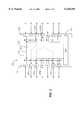
- FIG. 5shows only a portion of a 68 port device that would include 68 PRCs 305 as well as 68 busy bit segments 501 within busy bit unit 307.
- Each PRC 305is associated with one port 201 (shown in FIG. 2).
- each busy bit segment 501is associated with one port 201.
- Each PRC 305includes a connection to the crossbar connection logic 302 (shown in FIG. 3) that is one or more bits wide to meet the needs of a particular application.
- each PRC 305makes a multi-line parallel connection to CCL 302 using any available crossbar addressing technique.
- Each PRC 305includes a single busy bit clear (BB -- CLR) line that is coupled to the busy bit segment 501 associated with that port. Port availability is indicated by clearing the busy bit by asserting an active signal on the BB -- CLR line.
- BB -- CLRbusy bit clear
- Each busy bit segment 501includes a BB -- REQ interface to receive the BB REQ signal from each of the PRCs 305.
- Each busy bit segment 501also includes a response line (e.g., BB -- RSP[0]-BB -- RSP[67]) coupled to each PRC 305 as well as a single busy bit line (e.g., BB[0]) that is fanned out to each PRC 305.
- BB -- RSP[0]-BB -- RSP[67]coupled to each PRC 305 as well as a single busy bit line (e.g., BB[0]) that is fanned out to each PRC 305.
- each PRC 305is continuously aware of the busy/available status of each busy bit segment 501, and so aware of the availability of each port 201. A PRC 305 that issues a request does not have to wait for the addressed busy bit segment 501 to respond.
- the BB -- REQ signalis asserted in an unchecked manner to avoid any latency associated with blocking the BB -- REQ signal while evaluating the busy/available state of the destination port.
- the PRC 305 receiving the connection requestscans the appropriate BB line (i.e., one of lines BB[67:0] in FIG. 5) and its BB -- RSP lines (i.e., one of the lines BB -- RSP[67:0] in FIG. 5). If either the BB is set or the BB -- RSP is not set for the requested destination port, then a connection cannot be made and PRC 305 generates a destination port busy message back to the requesting port 201. If a connection is established (i.e., the BB is clear and the BB -- RSP is set) then the requesting PRC 305 generates a switch request to CCL 302 and an appropriate response message back to the requesting port 201.
- the present inventionis readily adapted to support broadcast and multicast groups.
- a single source port 201may request a connection to multiple destination ports 201 as each destination port 201 is intended to receive the same data.
- Prior switch implementations that set up connections one at a timehave added undesireable latency to multicast and broadcast implementations.
- a portion of the destination port address space(e.g., the address space defined by the 8-bits D0-D7 in FIG. 4) is reserved to indicate multicast/broadcast groups.
- multicast/broadcast requestscan be designated as specific request types such as those shown in Table 1 and allocated a unique encoding.
- a connect request message including a destination port address in the range of hex "0xFO" to hex "0xFF"identifies a multicast or broadcast connection.
- FIG. 6shows an example configuration mechanism that can be implemented in each PRC 305 or in a centralized multicast unit (not shown) that handles multicast configuration.
- a system administratormanually or automated preconfigures a switch 200 to define sixteen multicast/broadcast groups or sets.
- Each multicast/broadcast groupis associated with an entry 601 in a configuration register 600.
- Each group or setcorresponds to one of the sixteen addressess in the range of hex "0xFO" to hex "0xFF".
- Each multicast/broadcast groupcomprises a set of destination ports that can be concurrently connected to a single requesting source port. Port assignment to a multicast/broadcast group are typically done to meet specific requests of devices and users of the particular ports within a multicast/broadcast group.
- Each entry 601 in configuration register 600holds an enable bit in the preferred implementation so that the system administrator can selectively enable each multicast/broadcast group independently. For example, a logic "HIGH” stored in an entry 601 enables that multicast/broadcast group whereas a logic "LOW” disables that multicast/broadcast group. By disabling a particular entry 601 the corresponding address (i.e., an address in the range "0xF0 to 0xFF" can be used as a conventional unicast address.
- the requesting PRC 305initiates switch requests with CCL 302 to set up the connection(s) to available destination ports 201 and generates a message back to the port 201 associated with the requesting PRC 305 indicating which of the destination ports in the multicast/broadcast request were successfully arbitrated for.
Landscapes
- Engineering & Computer Science (AREA)
- Physics & Mathematics (AREA)
- General Engineering & Computer Science (AREA)
- Theoretical Computer Science (AREA)
- Mathematical Physics (AREA)
- Computer Hardware Design (AREA)
- General Physics & Mathematics (AREA)
- Multi Processors (AREA)
- Exchange Systems With Centralized Control (AREA)
- Data Exchanges In Wide-Area Networks (AREA)
- Use Of Switch Circuits For Exchanges And Methods Of Control Of Multiplex Exchanges (AREA)
- Telephonic Communication Services (AREA)
Abstract
Description
TABLE 1 ______________________________________Request BITS TYPE 0TYPE 1 ENCODED REQUEST TYPE ______________________________________ 0 0 Clear only 0 1 Clear andConnect Half Duplex 1 0 Connect Half Duplex Only 1 1 Connect Full Duplex ______________________________________
TABLE 2 ______________________________________ RESPONSE BITS DEFINITION ______________________________________ 000 Connected as a DestinationPort Half Duplex 001 Connected as a Source Port Half Duplex 010 Connected as a Source and Dest. Port Half Duplex 011 Connected as a SourcePort Full Duplex 100 Connected as a DestinationPort Full Duplex 101 Requested Destination Port is Busy and Connected as DestinationPort Half Duplex 110 Requested Destination Port is Busy 111 Source Port is Busy ______________________________________
Claims (24)
Priority Applications (5)
| Application Number | Priority Date | Filing Date | Title |
|---|---|---|---|
| US09/183,396US6138185A (en) | 1998-10-29 | 1998-10-29 | High performance crossbar switch |
| JP2000580396AJP2002529981A (en) | 1998-10-29 | 1999-08-17 | High performance crossbar switch |
| PCT/US1999/018907WO2000027136A1 (en) | 1998-10-29 | 1999-08-17 | High performance crossbar switch |
| EP99971620AEP1127470A4 (en) | 1998-10-29 | 1999-08-17 | High performance crossbar switch |
| AU60197/99AAU6019799A (en) | 1998-10-29 | 1999-08-17 | High performance crossbar switch |
Applications Claiming Priority (1)
| Application Number | Priority Date | Filing Date | Title |
|---|---|---|---|
| US09/183,396US6138185A (en) | 1998-10-29 | 1998-10-29 | High performance crossbar switch |
Publications (1)
| Publication Number | Publication Date |
|---|---|
| US6138185Atrue US6138185A (en) | 2000-10-24 |
Family
ID=22672628
Family Applications (1)
| Application Number | Title | Priority Date | Filing Date |
|---|---|---|---|
| US09/183,396Expired - LifetimeUS6138185A (en) | 1998-10-29 | 1998-10-29 | High performance crossbar switch |
Country Status (5)
| Country | Link |
|---|---|
| US (1) | US6138185A (en) |
| EP (1) | EP1127470A4 (en) |
| JP (1) | JP2002529981A (en) |
| AU (1) | AU6019799A (en) |
| WO (1) | WO2000027136A1 (en) |
Cited By (70)
| Publication number | Priority date | Publication date | Assignee | Title |
|---|---|---|---|---|
| US6317804B1 (en)* | 1998-11-30 | 2001-11-13 | Philips Semiconductors Inc. | Concurrent serial interconnect for integrating functional blocks in an integrated circuit device |
| US20010044870A1 (en)* | 2000-01-31 | 2001-11-22 | Fisher Rollie M. | I/O multiplexer and pin controller with serial and parallel capabilities for microprocessor based engine control |
| US20020023184A1 (en)* | 2000-08-07 | 2002-02-21 | Paul Harry V. | Fibre channel architecture |
| US6356952B1 (en)* | 1998-10-14 | 2002-03-12 | Accton Technology Corporation | Local area network hub with distributed communication ports and magnetically attachable battery box |
| US6473827B2 (en)* | 1998-12-22 | 2002-10-29 | Ncr Corporation | Distributed multi-fabric interconnect |
| US20020174244A1 (en)* | 2001-05-18 | 2002-11-21 | Telgen Corporation | System and method for coordinating, distributing and processing of data |
| US20020172221A1 (en)* | 2001-05-18 | 2002-11-21 | Telgen Corporation | Distributed communication device and architecture for balancing processing of real-time communication applications |
| US20020174258A1 (en)* | 2001-05-18 | 2002-11-21 | Dale Michele Zampetti | System and method for providing non-blocking shared structures |
| US20020191615A1 (en)* | 2001-06-13 | 2002-12-19 | Inrange Technologies Corporation | Method and apparatus for rendering a cell-based switch useful for frame based application protocols |
| WO2003014948A1 (en)* | 2001-08-07 | 2003-02-20 | Broadlight Ltd. | System architecture of a high bit rate switch module between functional units in a system on a chip |
| US20030041209A1 (en)* | 2001-08-22 | 2003-02-27 | Kirshtein Philip M. | Self-synchronizing half duplex matrix switch |
| WO2003017103A1 (en)* | 2001-08-17 | 2003-02-27 | Mcdata Corporation | Compact, shared route lookup table for a fibre channel switch |
| US20030046496A1 (en)* | 2001-08-17 | 2003-03-06 | Mitchem William J. | Multi-rate shared memory architecture for frame storage and switching |
| US20030058802A1 (en)* | 2001-09-24 | 2003-03-27 | Internet Machines Corporation | Adaptive rate controlled router system and method |
| US20030072303A1 (en)* | 2001-10-10 | 2003-04-17 | Woods Gregory K. | Multiple-interface port multiplexer |
| US6556953B2 (en) | 2001-04-09 | 2003-04-29 | Mcdata Corporation | Automatic testing of redundant switching element and automatic switchover |
| US20030088694A1 (en)* | 2001-11-02 | 2003-05-08 | Internet Machines Corporation | Multicasting method and switch |
| US20030093648A1 (en)* | 2001-11-13 | 2003-05-15 | Moyer William C. | Method and apparatus for interfacing a processor to a coprocessor |
| US20030135682A1 (en)* | 2002-01-02 | 2003-07-17 | Fanning Blaise B. | Point-to-point busing and arrangement |
| US6597692B1 (en)* | 1999-04-21 | 2003-07-22 | Hewlett-Packard Development, L.P. | Scalable, re-configurable crossbar switch architecture for multi-processor system interconnection networks |
| US6606322B2 (en) | 2001-08-17 | 2003-08-12 | Mcdata Corporation | Route lookup caching for a fiber channel switch |
| US6608819B1 (en) | 1999-01-12 | 2003-08-19 | Mcdata Corporation | Method for scoring queued frames for selective transmission through a switch |
| US6633946B1 (en)* | 1999-09-28 | 2003-10-14 | Sun Microsystems, Inc. | Flexible switch-based I/O system interconnect |
| US20040028056A1 (en)* | 1999-01-12 | 2004-02-12 | Mitchem W. Jeffrey | Method for scoring queued frames for selective transmission through a switch |
| US6715023B1 (en)* | 1999-09-23 | 2004-03-30 | Altera Corporation | PCI bus switch architecture |
| US20040081108A1 (en)* | 2002-10-02 | 2004-04-29 | Andiamo Systems | Arbitration system |
| US20040088469A1 (en)* | 2002-10-30 | 2004-05-06 | Levy Paul S. | Links having flexible lane allocation |
| US20040165590A1 (en)* | 2003-02-25 | 2004-08-26 | Internet Machines Corp. | Network processor having bypass capability |
| US20040168041A1 (en)* | 2003-02-25 | 2004-08-26 | Internet Machines Corp. | Flexible interface device |
| US20040221106A1 (en)* | 2001-02-28 | 2004-11-04 | Perego Richard E. | Upgradable memory system with reconfigurable interconnect |
| US20050083721A1 (en)* | 2001-09-07 | 2005-04-21 | Hampel Craig E. | Granularity memory column access |
| US6889304B2 (en) | 2001-02-28 | 2005-05-03 | Rambus Inc. | Memory device supporting a dynamically configurable core organization |
| US20050097388A1 (en)* | 2003-11-05 | 2005-05-05 | Kris Land | Data distributor |
| US20050102417A1 (en)* | 2002-10-16 | 2005-05-12 | Kai Fechner | No-addressing modular-assembly Ethernet switch with a G.Link |
| US20050108444A1 (en)* | 2003-11-19 | 2005-05-19 | Flauaus Gary R. | Method of detecting and monitoring fabric congestion |
| US20050147114A1 (en)* | 2004-01-05 | 2005-07-07 | Heath Stewart | Multicasting in a shared address space |
| US20050286747A1 (en)* | 2003-04-28 | 2005-12-29 | Matsushita Electric Industrial Co,. Ltd. | Artificial eye distinguishing method and device, artificial eye distinguishing program, iris recognition method, false printed matter distinguishing method, and image distinguishing method |
| US20060039227A1 (en)* | 2004-08-17 | 2006-02-23 | Lawrence Lai | Memory device having staggered memory operations |
| US20060067146A1 (en)* | 2004-09-30 | 2006-03-30 | Steven Woo | Integrated circuit memory system having dynamic memory bank count and page size |
| US20060072366A1 (en)* | 2004-09-30 | 2006-04-06 | Ware Frederick A | Multi-column addressing mode memory system including an integrated circuit memory device |
| US7058750B1 (en)* | 2000-05-10 | 2006-06-06 | Intel Corporation | Scalable distributed memory and I/O multiprocessor system |
| US20060133124A1 (en)* | 1999-12-23 | 2006-06-22 | Nader Gamini | Semiconductor package with a controlled impedance bus and method of forming same |
| US20060248305A1 (en)* | 2005-04-13 | 2006-11-02 | Wayne Fang | Memory device having width-dependent output latency |
| US20070081539A1 (en)* | 2002-05-16 | 2007-04-12 | Nadim Shaikli | Method For Reordering Sequenced Packets |
| US20080013535A1 (en)* | 2001-10-03 | 2008-01-17 | Khacherian Todd L | Data Switch and Switch Fabric |
| US20080059687A1 (en)* | 2006-08-31 | 2008-03-06 | Peter Mayer | System and method of connecting a processing unit with a memory unit |
| US20080172510A1 (en)* | 2007-01-16 | 2008-07-17 | Wei-Jen Chen | Parallel bus architecture and related method for interconnecting sub-systems utilizing a parallel bus |
| US20080187130A1 (en)* | 2003-05-19 | 2008-08-07 | Sture Roos | Cross-Connect Arrangement and Switch Matrix |
| US20080195845A1 (en)* | 2005-01-07 | 2008-08-14 | Freescale Semiconductor, Inc. | Data processing system having flexible instruction capability and selection mechanism |
| US20080304504A1 (en)* | 2003-11-18 | 2008-12-11 | Heath Stewart | PCI Express Switch with Backwards Compatibility |
| US7500075B1 (en) | 2001-04-17 | 2009-03-03 | Rambus Inc. | Mechanism for enabling full data bus utilization without increasing data granularity |
| CN101611452A (en)* | 2006-10-23 | 2009-12-23 | 提琴存储器公司 | Skew management in an interconnect system |
| US7769929B1 (en) | 2005-10-28 | 2010-08-03 | Altera Corporation | Design tool selection and implementation of port adapters |
| US7779286B1 (en)* | 2005-10-28 | 2010-08-17 | Altera Corporation | Design tool clock domain crossing management |
| US20110199925A1 (en)* | 2000-09-06 | 2011-08-18 | Juniper Networks, Inc. | Packet switching equipment and switching control method |
| US20120020365A1 (en)* | 2005-03-31 | 2012-01-26 | Denham Martin S | Modular interconnect structure |
| US8112655B2 (en) | 2005-04-21 | 2012-02-07 | Violin Memory, Inc. | Mesosynchronous data bus apparatus and method of data transmission |
| DE102005062576B4 (en)* | 2005-12-27 | 2012-10-25 | OCé PRINTING SYSTEMS GMBH | Electronic control device with a parallel data bus |
| US8364926B2 (en) | 2006-05-02 | 2013-01-29 | Rambus Inc. | Memory module with reduced access granularity |
| US20130046909A1 (en)* | 2009-11-18 | 2013-02-21 | ST- Ericsson SA | Method and Apparatus of Master-to-Master Transfer of Data on a Chip and System on Chip |
| US8452929B2 (en) | 2005-04-21 | 2013-05-28 | Violin Memory Inc. | Method and system for storage of data in non-volatile media |
| US20130208727A1 (en)* | 2010-07-21 | 2013-08-15 | Gnodal Limited | Apparatus & method |
| US8595459B2 (en) | 2004-11-29 | 2013-11-26 | Rambus Inc. | Micro-threaded memory |
| US8726064B2 (en) | 2005-04-21 | 2014-05-13 | Violin Memory Inc. | Interconnection system |
| US20140269756A1 (en)* | 2013-03-14 | 2014-09-18 | International Business Machines Corporation | Port membership table partitioning |
| US9268719B2 (en) | 2011-08-05 | 2016-02-23 | Rambus Inc. | Memory signal buffers and modules supporting variable access granularity |
| US9286198B2 (en) | 2005-04-21 | 2016-03-15 | Violin Memory | Method and system for storage of data in non-volatile media |
| US9582449B2 (en) | 2005-04-21 | 2017-02-28 | Violin Memory, Inc. | Interconnection system |
| US10176861B2 (en) | 2005-04-21 | 2019-01-08 | Violin Systems Llc | RAIDed memory system management |
| US10476492B2 (en)* | 2018-11-27 | 2019-11-12 | Intel Corporation | Structures and operations of integrated circuits having network of configurable switches |
Citations (11)
| Publication number | Priority date | Publication date | Assignee | Title |
|---|---|---|---|---|
| US3597738A (en)* | 1969-03-10 | 1971-08-03 | Chester Electronic Lab Inc | Switching system using divided crossbar switch |
| US4605928A (en)* | 1983-10-24 | 1986-08-12 | International Business Machines Corporation | Fault-tolerant array of cross-point switching matrices |
| US4630045A (en)* | 1983-10-24 | 1986-12-16 | International Business Machines Corporation | Controller for a cross-point switching matrix |
| US4635250A (en)* | 1984-04-13 | 1987-01-06 | International Business Machines Corporation | Full-duplex one-sided cross-point switch |
| US5280591A (en)* | 1991-07-22 | 1994-01-18 | International Business Machines, Corporation | Centralized backplane bus arbiter for multiprocessor systems |
| US5392422A (en)* | 1992-06-26 | 1995-02-21 | Sun Microsystems, Inc. | Source synchronized metastable free bus |
| US5420853A (en)* | 1993-04-05 | 1995-05-30 | Motorola, Inc. | Self controlling crossbar switch and method |
| US5555543A (en)* | 1995-01-03 | 1996-09-10 | International Business Machines Corporation | Crossbar switch apparatus and protocol |
| US5689644A (en)* | 1996-03-25 | 1997-11-18 | I-Cube, Inc. | Network switch with arbitration sytem |
| US5838937A (en)* | 1995-12-23 | 1998-11-17 | Electronics And Telecommunications Research Institute | Data transmitting/receiving method using distributed path control in data switching system |
| US5887144A (en)* | 1996-11-20 | 1999-03-23 | International Business Machines Corp. | Method and system for increasing the load and expansion capabilities of a bus through the use of in-line switches |
Family Cites Families (1)
| Publication number | Priority date | Publication date | Assignee | Title |
|---|---|---|---|---|
| US5754120A (en)* | 1995-12-21 | 1998-05-19 | Lucent Technologies | Network congestion measurement method and apparatus |
- 1998
- 1998-10-29USUS09/183,396patent/US6138185A/ennot_activeExpired - Lifetime
- 1999
- 1999-08-17WOPCT/US1999/018907patent/WO2000027136A1/ennot_activeApplication Discontinuation
- 1999-08-17EPEP99971620Apatent/EP1127470A4/ennot_activeWithdrawn
- 1999-08-17JPJP2000580396Apatent/JP2002529981A/enactivePending
- 1999-08-17AUAU60197/99Apatent/AU6019799A/ennot_activeAbandoned
Patent Citations (11)
| Publication number | Priority date | Publication date | Assignee | Title |
|---|---|---|---|---|
| US3597738A (en)* | 1969-03-10 | 1971-08-03 | Chester Electronic Lab Inc | Switching system using divided crossbar switch |
| US4605928A (en)* | 1983-10-24 | 1986-08-12 | International Business Machines Corporation | Fault-tolerant array of cross-point switching matrices |
| US4630045A (en)* | 1983-10-24 | 1986-12-16 | International Business Machines Corporation | Controller for a cross-point switching matrix |
| US4635250A (en)* | 1984-04-13 | 1987-01-06 | International Business Machines Corporation | Full-duplex one-sided cross-point switch |
| US5280591A (en)* | 1991-07-22 | 1994-01-18 | International Business Machines, Corporation | Centralized backplane bus arbiter for multiprocessor systems |
| US5392422A (en)* | 1992-06-26 | 1995-02-21 | Sun Microsystems, Inc. | Source synchronized metastable free bus |
| US5420853A (en)* | 1993-04-05 | 1995-05-30 | Motorola, Inc. | Self controlling crossbar switch and method |
| US5555543A (en)* | 1995-01-03 | 1996-09-10 | International Business Machines Corporation | Crossbar switch apparatus and protocol |
| US5838937A (en)* | 1995-12-23 | 1998-11-17 | Electronics And Telecommunications Research Institute | Data transmitting/receiving method using distributed path control in data switching system |
| US5689644A (en)* | 1996-03-25 | 1997-11-18 | I-Cube, Inc. | Network switch with arbitration sytem |
| US5887144A (en)* | 1996-11-20 | 1999-03-23 | International Business Machines Corp. | Method and system for increasing the load and expansion capabilities of a bus through the use of in-line switches |
Cited By (159)
| Publication number | Priority date | Publication date | Assignee | Title |
|---|---|---|---|---|
| US6356952B1 (en)* | 1998-10-14 | 2002-03-12 | Accton Technology Corporation | Local area network hub with distributed communication ports and magnetically attachable battery box |
| US6317804B1 (en)* | 1998-11-30 | 2001-11-13 | Philips Semiconductors Inc. | Concurrent serial interconnect for integrating functional blocks in an integrated circuit device |
| US6473827B2 (en)* | 1998-12-22 | 2002-10-29 | Ncr Corporation | Distributed multi-fabric interconnect |
| US6608819B1 (en) | 1999-01-12 | 2003-08-19 | Mcdata Corporation | Method for scoring queued frames for selective transmission through a switch |
| US7848253B2 (en) | 1999-01-12 | 2010-12-07 | Mcdata Corporation | Method for scoring queued frames for selective transmission through a switch |
| US20040028056A1 (en)* | 1999-01-12 | 2004-02-12 | Mitchem W. Jeffrey | Method for scoring queued frames for selective transmission through a switch |
| US7382736B2 (en) | 1999-01-12 | 2008-06-03 | Mcdata Corporation | Method for scoring queued frames for selective transmission through a switch |
| US6597692B1 (en)* | 1999-04-21 | 2003-07-22 | Hewlett-Packard Development, L.P. | Scalable, re-configurable crossbar switch architecture for multi-processor system interconnection networks |
| US6715023B1 (en)* | 1999-09-23 | 2004-03-30 | Altera Corporation | PCI bus switch architecture |
| US6633946B1 (en)* | 1999-09-28 | 2003-10-14 | Sun Microsystems, Inc. | Flexible switch-based I/O system interconnect |
| US20060133124A1 (en)* | 1999-12-23 | 2006-06-22 | Nader Gamini | Semiconductor package with a controlled impedance bus and method of forming same |
| US8076759B2 (en) | 1999-12-23 | 2011-12-13 | Rambus Inc. | Semiconductor package with a controlled impedance bus and method of forming same |
| US7626248B2 (en) | 1999-12-23 | 2009-12-01 | Rambus Inc. | Semiconductor package with a controlled impedance bus |
| US20100072605A1 (en)* | 1999-12-23 | 2010-03-25 | Nader Gamini | Semiconductor Package With a Controlled Impedance Bus and Method of Forming Same |
| US6978340B2 (en)* | 2000-01-31 | 2005-12-20 | Visteon Corporation | I/O multiplexer and pin controller with serial and parallel capabilities for microprocessor based engine control |
| US20010044870A1 (en)* | 2000-01-31 | 2001-11-22 | Fisher Rollie M. | I/O multiplexer and pin controller with serial and parallel capabilities for microprocessor based engine control |
| US7058750B1 (en)* | 2000-05-10 | 2006-06-06 | Intel Corporation | Scalable distributed memory and I/O multiprocessor system |
| US7343442B2 (en) | 2000-05-10 | 2008-03-11 | Intel Corporation | Scalable distributed memory and I/O multiprocessor systems and associated methods |
| US7930464B2 (en) | 2000-05-10 | 2011-04-19 | Intel Corporation | Scalable memory and I/O multiprocessor systems |
| US20110185101A1 (en)* | 2000-05-10 | 2011-07-28 | Rankin Linda J | Scalable distributed memory and i/o multiprocessor system |
| US7603508B2 (en)* | 2000-05-10 | 2009-10-13 | Intel Corporation | Scalable distributed memory and I/O multiprocessor systems and associated methods |
| US8745306B2 (en)* | 2000-05-10 | 2014-06-03 | Intel Corporation | Scalable distributed memory and I/O multiprocessor system |
| US20080114919A1 (en)* | 2000-05-10 | 2008-05-15 | Intel Corporation | Scalable distributed memory and i/o multiprocessor systems and associated methods |
| US20070106833A1 (en)* | 2000-05-10 | 2007-05-10 | Intel Corporation | Scalable distributed memory and I/O multiprocessor systems and associated methods |
| US20090319717A1 (en)* | 2000-05-10 | 2009-12-24 | Intel Corporation | Scalable distributed memory and i/o multiprocessor systems and associated methods |
| US8255605B2 (en) | 2000-05-10 | 2012-08-28 | Intel Corporation | Scalable distributed memory and I/O multiprocessor system |
| US20120317328A1 (en)* | 2000-05-10 | 2012-12-13 | Rankin Linda J | Scalable distributed memory and i/o multiprocessor system |
| US20020023184A1 (en)* | 2000-08-07 | 2002-02-21 | Paul Harry V. | Fibre channel architecture |
| US6981078B2 (en) | 2000-08-07 | 2005-12-27 | Computer Network Technology Corporation | Fiber channel architecture |
| US20110199925A1 (en)* | 2000-09-06 | 2011-08-18 | Juniper Networks, Inc. | Packet switching equipment and switching control method |
| US8769234B2 (en) | 2001-02-28 | 2014-07-01 | Rambus Inc. | Memory modules and devices supporting configurable data widths |
| US9257151B2 (en) | 2001-02-28 | 2016-02-09 | Rambus Inc. | Printed-circuit board supporting memory systems with multiple data-bus configurations |
| US20040221106A1 (en)* | 2001-02-28 | 2004-11-04 | Perego Richard E. | Upgradable memory system with reconfigurable interconnect |
| US8412906B2 (en) | 2001-02-28 | 2013-04-02 | Rambus Inc. | Memory apparatus supporting multiple width configurations |
| US6889304B2 (en) | 2001-02-28 | 2005-05-03 | Rambus Inc. | Memory device supporting a dynamically configurable core organization |
| US20060236031A1 (en)* | 2001-02-28 | 2006-10-19 | Rambus Inc. | Upgradable memory system with reconfigurable interconnect |
| US7577789B2 (en) | 2001-02-28 | 2009-08-18 | Rambus Inc. | Upgradable memory system with reconfigurable interconnect |
| US9824036B2 (en) | 2001-02-28 | 2017-11-21 | Rambus Inc. | Memory systems with multiple modules supporting simultaneous access responsive to common memory commands |
| US7610447B2 (en) | 2001-02-28 | 2009-10-27 | Rambus Inc. | Upgradable memory system with reconfigurable interconnect |
| US6643602B2 (en) | 2001-04-09 | 2003-11-04 | Mcdata Corporation | Automatic testing of redundant switching element and automatic switchover |
| US6556953B2 (en) | 2001-04-09 | 2003-04-29 | Mcdata Corporation | Automatic testing of redundant switching element and automatic switchover |
| US7500075B1 (en) | 2001-04-17 | 2009-03-03 | Rambus Inc. | Mechanism for enabling full data bus utilization without increasing data granularity |
| US20020172221A1 (en)* | 2001-05-18 | 2002-11-21 | Telgen Corporation | Distributed communication device and architecture for balancing processing of real-time communication applications |
| US20020174258A1 (en)* | 2001-05-18 | 2002-11-21 | Dale Michele Zampetti | System and method for providing non-blocking shared structures |
| US20020174244A1 (en)* | 2001-05-18 | 2002-11-21 | Telgen Corporation | System and method for coordinating, distributing and processing of data |
| US20070268907A1 (en)* | 2001-06-13 | 2007-11-22 | Paul Harry V | Method and apparatus for rendering a cell-based switch useful for frame based application protocols |
| US7218636B2 (en)* | 2001-06-13 | 2007-05-15 | Inrange Technology Corporation | Method and apparatus for rendering a cell-based switch useful for frame based application protocols |
| US20020191615A1 (en)* | 2001-06-13 | 2002-12-19 | Inrange Technologies Corporation | Method and apparatus for rendering a cell-based switch useful for frame based application protocols |
| US7394814B2 (en) | 2001-06-13 | 2008-07-01 | Paul Harry V | Method and apparatus for rendering a cell-based switch useful for frame based application protocols |
| WO2003014948A1 (en)* | 2001-08-07 | 2003-02-20 | Broadlight Ltd. | System architecture of a high bit rate switch module between functional units in a system on a chip |
| US7054312B2 (en) | 2001-08-17 | 2006-05-30 | Mcdata Corporation | Multi-rate shared memory architecture for frame storage and switching |
| US20030046496A1 (en)* | 2001-08-17 | 2003-03-06 | Mitchem William J. | Multi-rate shared memory architecture for frame storage and switching |
| US6804245B2 (en)* | 2001-08-17 | 2004-10-12 | Mcdata Corporation | Compact, shared route lookup table for a fiber channel switch |
| US20030043834A1 (en)* | 2001-08-17 | 2003-03-06 | Mitchem William J. | Compact, shared route lookup table for a fibre channel switch |
| WO2003017103A1 (en)* | 2001-08-17 | 2003-02-27 | Mcdata Corporation | Compact, shared route lookup table for a fibre channel switch |
| US6606322B2 (en) | 2001-08-17 | 2003-08-12 | Mcdata Corporation | Route lookup caching for a fiber channel switch |
| US20030041209A1 (en)* | 2001-08-22 | 2003-02-27 | Kirshtein Philip M. | Self-synchronizing half duplex matrix switch |
| US7062596B2 (en)* | 2001-08-22 | 2006-06-13 | Avocent Corporation | Self-synchronizing half duplex matrix switch |
| US20050083721A1 (en)* | 2001-09-07 | 2005-04-21 | Hampel Craig E. | Granularity memory column access |
| US7848251B2 (en) | 2001-09-24 | 2010-12-07 | Topside Research, Llc | Adaptive rate control |
| US8213322B2 (en) | 2001-09-24 | 2012-07-03 | Topside Research, Llc | Dynamically distributed weighted fair queuing |
| US20090279560A1 (en)* | 2001-09-24 | 2009-11-12 | Jones Jason A | Adaptive Rate Control |
| US20030058802A1 (en)* | 2001-09-24 | 2003-03-27 | Internet Machines Corporation | Adaptive rate controlled router system and method |
| US20080013535A1 (en)* | 2001-10-03 | 2008-01-17 | Khacherian Todd L | Data Switch and Switch Fabric |
| US7782849B2 (en) | 2001-10-03 | 2010-08-24 | Forestay Research, Llc | Data switch and switch fabric |
| US20030072303A1 (en)* | 2001-10-10 | 2003-04-17 | Woods Gregory K. | Multiple-interface port multiplexer |
| CN100357924C (en)* | 2001-10-10 | 2007-12-26 | 高通股份有限公司 | Multiple-interface port multiplexer |
| US7136379B2 (en) | 2001-10-10 | 2006-11-14 | Qualcomm Incorporated | Multiple-interface port multiplexer |
| WO2003032177A1 (en)* | 2001-10-10 | 2003-04-17 | Qualcomm, Incorporated | Multiple-interface port multiplexer |
| US20030088694A1 (en)* | 2001-11-02 | 2003-05-08 | Internet Machines Corporation | Multicasting method and switch |
| US7228401B2 (en)* | 2001-11-13 | 2007-06-05 | Freescale Semiconductor, Inc. | Interfacing a processor to a coprocessor in which the processor selectively broadcasts to or selectively alters an execution mode of the coprocessor |
| US20030093648A1 (en)* | 2001-11-13 | 2003-05-15 | Moyer William C. | Method and apparatus for interfacing a processor to a coprocessor |
| US20030135682A1 (en)* | 2002-01-02 | 2003-07-17 | Fanning Blaise B. | Point-to-point busing and arrangement |
| US6918001B2 (en)* | 2002-01-02 | 2005-07-12 | Intel Corporation | Point-to-point busing and arrangement |
| US20070081539A1 (en)* | 2002-05-16 | 2007-04-12 | Nadim Shaikli | Method For Reordering Sequenced Packets |
| US7668187B2 (en) | 2002-05-16 | 2010-02-23 | Topside Research, Llc | Method for reordering sequenced packets |
| US7646780B2 (en) | 2002-05-16 | 2010-01-12 | Topside Research, Llc | System for reordering sequenced based packets in a switching network |
| US20070081558A1 (en)* | 2002-05-16 | 2007-04-12 | Nadim Shaikli | System For Reordering Sequenced Based Packets In A Switching Network |
| US20050157579A1 (en)* | 2002-06-26 | 2005-07-21 | Perego Richard E. | Memory device supporting a dynamically configurable core organization |
| US20040081108A1 (en)* | 2002-10-02 | 2004-04-29 | Andiamo Systems | Arbitration system |
| US20050102417A1 (en)* | 2002-10-16 | 2005-05-12 | Kai Fechner | No-addressing modular-assembly Ethernet switch with a G.Link |
| US7426205B2 (en)* | 2002-10-16 | 2008-09-16 | Phoenix Contact Gmbh & Co. Kg | No-addressing modular-assembly Ethernet switch with a G.Link |
| US7802049B2 (en)* | 2002-10-30 | 2010-09-21 | Intel Corporation | Links having flexible lane allocation |
| US20040088469A1 (en)* | 2002-10-30 | 2004-05-06 | Levy Paul S. | Links having flexible lane allocation |
| US8190858B2 (en) | 2003-02-25 | 2012-05-29 | Topside Research, Llc | Interface device for interfacing a main processor to processing engines and classifier engines, and methods for configuring and operating interface devices |
| US7990987B2 (en) | 2003-02-25 | 2011-08-02 | Topside Research, Llc | Network processor having bypass capability |
| US20040168041A1 (en)* | 2003-02-25 | 2004-08-26 | Internet Machines Corp. | Flexible interface device |
| US20040165590A1 (en)* | 2003-02-25 | 2004-08-26 | Internet Machines Corp. | Network processor having bypass capability |
| US7660443B2 (en) | 2003-04-28 | 2010-02-09 | Panasonic Corporation | Artificial eye distinguishing method and device, artificial eye distinguishing program, iris recognition method, false printed matter distinguishing method, and image distinguishing method |
| US20050286747A1 (en)* | 2003-04-28 | 2005-12-29 | Matsushita Electric Industrial Co,. Ltd. | Artificial eye distinguishing method and device, artificial eye distinguishing program, iris recognition method, false printed matter distinguishing method, and image distinguishing method |
| US20080187130A1 (en)* | 2003-05-19 | 2008-08-07 | Sture Roos | Cross-Connect Arrangement and Switch Matrix |
| US20050097388A1 (en)* | 2003-11-05 | 2005-05-05 | Kris Land | Data distributor |
| US20110016258A1 (en)* | 2003-11-18 | 2011-01-20 | Heath Stewart | Routing Data Units Between Different Address Domains |
| US7945722B2 (en)* | 2003-11-18 | 2011-05-17 | Internet Machines, Llc | Routing data units between different address domains |
| US7814259B2 (en) | 2003-11-18 | 2010-10-12 | Internet Machines, Llc | PCI express switch with backwards compatibility |
| US20080304504A1 (en)* | 2003-11-18 | 2008-12-11 | Heath Stewart | PCI Express Switch with Backwards Compatibility |
| US20050108444A1 (en)* | 2003-11-19 | 2005-05-19 | Flauaus Gary R. | Method of detecting and monitoring fabric congestion |
| US7539190B2 (en)* | 2004-01-05 | 2009-05-26 | Topside Research, Llc | Multicasting in a shared address space |
| US20050147114A1 (en)* | 2004-01-05 | 2005-07-07 | Heath Stewart | Multicasting in a shared address space |
| US20090228568A1 (en)* | 2004-01-05 | 2009-09-10 | Heath Stewart | Multicasting Computer Bus Switch |
| US8190808B2 (en) | 2004-08-17 | 2012-05-29 | Rambus Inc. | Memory device having staggered memory operations |
| US20060039227A1 (en)* | 2004-08-17 | 2006-02-23 | Lawrence Lai | Memory device having staggered memory operations |
| US20110153932A1 (en)* | 2004-09-30 | 2011-06-23 | Rambus Inc. | Multi-column addressing mode memory system including an integrated circuit memory device |
| US7755968B2 (en) | 2004-09-30 | 2010-07-13 | Rambus Inc. | Integrated circuit memory device having dynamic memory bank count and page size |
| US7505356B2 (en) | 2004-09-30 | 2009-03-17 | Rambus Inc. | Multi-column addressing mode memory system including an integrated circuit memory device |
| US8432766B2 (en) | 2004-09-30 | 2013-04-30 | Rambus Inc. | Multi-column addressing mode memory system including an integrated circuit memory device |
| US7254075B2 (en) | 2004-09-30 | 2007-08-07 | Rambus Inc. | Integrated circuit memory system having dynamic memory bank count and page size |
| US20060072366A1 (en)* | 2004-09-30 | 2006-04-06 | Ware Frederick A | Multi-column addressing mode memory system including an integrated circuit memory device |
| US8050134B2 (en) | 2004-09-30 | 2011-11-01 | Rambus Inc. | Multi-column addressing mode memory system including an integrated circuit memory device |
| US20080062807A1 (en)* | 2004-09-30 | 2008-03-13 | Ware Frederick A | Multi-column addressing mode memory system including an integrated circuit memory device |
| US20060067146A1 (en)* | 2004-09-30 | 2006-03-30 | Steven Woo | Integrated circuit memory system having dynamic memory bank count and page size |
| US7280428B2 (en) | 2004-09-30 | 2007-10-09 | Rambus Inc. | Multi-column addressing mode memory system including an integrated circuit memory device |
| US20070268765A1 (en)* | 2004-09-30 | 2007-11-22 | Steven Woo | Integrated Circuit Memory Device Having Dynamic Memory Bank Count and Page Size |
| US8908466B2 (en) | 2004-09-30 | 2014-12-09 | Rambus Inc. | Multi-column addressing mode memory system including an integrated circuit memory device |
| US8154947B2 (en) | 2004-09-30 | 2012-04-10 | Rambus Inc. | Multi-column addressing mode memory system including an integrated circuit memory device |
| US11797227B2 (en) | 2004-11-29 | 2023-10-24 | Rambus Inc. | Memory controller for micro-threaded memory operations |
| US9292223B2 (en) | 2004-11-29 | 2016-03-22 | Rambus Inc. | Micro-threaded memory |
| US9652176B2 (en) | 2004-11-29 | 2017-05-16 | Rambus Inc. | Memory controller for micro-threaded memory operations |
| US10331379B2 (en) | 2004-11-29 | 2019-06-25 | Rambus Inc. | Memory controller for micro-threaded memory operations |
| US8595459B2 (en) | 2004-11-29 | 2013-11-26 | Rambus Inc. | Micro-threaded memory |
| US20080195845A1 (en)* | 2005-01-07 | 2008-08-14 | Freescale Semiconductor, Inc. | Data processing system having flexible instruction capability and selection mechanism |
| US20120020365A1 (en)* | 2005-03-31 | 2012-01-26 | Denham Martin S | Modular interconnect structure |
| US9363203B2 (en)* | 2005-03-31 | 2016-06-07 | Intel Corporation | Modular interconnect structure |
| US20060248305A1 (en)* | 2005-04-13 | 2006-11-02 | Wayne Fang | Memory device having width-dependent output latency |
| US8452929B2 (en) | 2005-04-21 | 2013-05-28 | Violin Memory Inc. | Method and system for storage of data in non-volatile media |
| US9286198B2 (en) | 2005-04-21 | 2016-03-15 | Violin Memory | Method and system for storage of data in non-volatile media |
| US10417159B2 (en) | 2005-04-21 | 2019-09-17 | Violin Systems Llc | Interconnection system |
| US8726064B2 (en) | 2005-04-21 | 2014-05-13 | Violin Memory Inc. | Interconnection system |
| US10176861B2 (en) | 2005-04-21 | 2019-01-08 | Violin Systems Llc | RAIDed memory system management |
| US9727263B2 (en) | 2005-04-21 | 2017-08-08 | Violin Memory, Inc. | Method and system for storage of data in a non-volatile media |
| US9582449B2 (en) | 2005-04-21 | 2017-02-28 | Violin Memory, Inc. | Interconnection system |
| US8112655B2 (en) | 2005-04-21 | 2012-02-07 | Violin Memory, Inc. | Mesosynchronous data bus apparatus and method of data transmission |
| US7779286B1 (en)* | 2005-10-28 | 2010-08-17 | Altera Corporation | Design tool clock domain crossing management |
| US7769929B1 (en) | 2005-10-28 | 2010-08-03 | Altera Corporation | Design tool selection and implementation of port adapters |
| US8706931B1 (en) | 2005-10-28 | 2014-04-22 | Altera Corporation | Tool selection and implementation of port adapters |
| US8286025B1 (en) | 2005-10-28 | 2012-10-09 | Altera Corporation | Selection of port adapters for clock crossing boundaries |
| DE102005062576B4 (en)* | 2005-12-27 | 2012-10-25 | OCé PRINTING SYSTEMS GMBH | Electronic control device with a parallel data bus |
| US9256557B2 (en) | 2006-05-02 | 2016-02-09 | Rambus Inc. | Memory controller for selective rank or subrank access |
| US11467986B2 (en) | 2006-05-02 | 2022-10-11 | Rambus Inc. | Memory controller for selective rank or subrank access |
| US10795834B2 (en) | 2006-05-02 | 2020-10-06 | Rambus Inc. | Memory controller for selective rank or subrank access |
| US8364926B2 (en) | 2006-05-02 | 2013-01-29 | Rambus Inc. | Memory module with reduced access granularity |
| US10191866B2 (en) | 2006-05-02 | 2019-01-29 | Rambus Inc. | Memory controller for selective rank or subrank access |
| US20080059687A1 (en)* | 2006-08-31 | 2008-03-06 | Peter Mayer | System and method of connecting a processing unit with a memory unit |
| US20120079163A1 (en)* | 2006-10-23 | 2012-03-29 | Violin Memory, Inc. | Skew management in an interconnection system |
| CN101611452A (en)* | 2006-10-23 | 2009-12-23 | 提琴存储器公司 | Skew management in an interconnect system |
| US8090973B2 (en)* | 2006-10-23 | 2012-01-03 | Violin Memory, Inc. | Skew management in an interconnection system |
| US8028186B2 (en)* | 2006-10-23 | 2011-09-27 | Violin Memory, Inc. | Skew management in an interconnection system |
| US8806262B2 (en)* | 2006-10-23 | 2014-08-12 | Violin Memory, Inc. | Skew management in an interconnection system |
| US20080172510A1 (en)* | 2007-01-16 | 2008-07-17 | Wei-Jen Chen | Parallel bus architecture and related method for interconnecting sub-systems utilizing a parallel bus |
| US9104819B2 (en)* | 2009-11-18 | 2015-08-11 | St-Ericsson Sa | Multi-master bus architecture for system-on-chip |
| US20130046909A1 (en)* | 2009-11-18 | 2013-02-21 | ST- Ericsson SA | Method and Apparatus of Master-to-Master Transfer of Data on a Chip and System on Chip |
| US9203739B2 (en)* | 2010-07-21 | 2015-12-01 | Cray Uk Limited | Adaptive routing apparatus and method |
| US20130208727A1 (en)* | 2010-07-21 | 2013-08-15 | Gnodal Limited | Apparatus & method |
| US9666250B2 (en) | 2011-08-05 | 2017-05-30 | Rambus Inc. | Memory signal buffers and modules supporting variable access granularity |
| US9268719B2 (en) | 2011-08-05 | 2016-02-23 | Rambus Inc. | Memory signal buffers and modules supporting variable access granularity |
| US20140269756A1 (en)* | 2013-03-14 | 2014-09-18 | International Business Machines Corporation | Port membership table partitioning |
| US9054947B2 (en)* | 2013-03-14 | 2015-06-09 | International Business Machines Corporation | Port membership table partitioning |
| US9215128B2 (en)* | 2013-03-14 | 2015-12-15 | International Business Machines Corporation | Port membership table partitioning |
| US10476492B2 (en)* | 2018-11-27 | 2019-11-12 | Intel Corporation | Structures and operations of integrated circuits having network of configurable switches |
Also Published As
| Publication number | Publication date |
|---|---|
| EP1127470A1 (en) | 2001-08-29 |
| WO2000027136A1 (en) | 2000-05-11 |
| JP2002529981A (en) | 2002-09-10 |
| EP1127470A4 (en) | 2005-02-09 |
| AU6019799A (en) | 2000-05-22 |
Similar Documents
| Publication | Publication Date | Title |
|---|---|---|
| US6138185A (en) | High performance crossbar switch | |
| KR102803151B1 (en) | Procedure for implementing source-based routing within the interconnect fabric of a system-on-chip | |
| US5592610A (en) | Method and apparatus for enhancing the fault-tolerance of a network | |
| US7197536B2 (en) | Primitive communication mechanism for adjacent nodes in a clustered computer system | |
| US4623996A (en) | Packet switched multiple queue NXM switch node and processing method | |
| US6950394B1 (en) | Methods and systems to transfer information using an alternative routing associated with a communication network | |
| US7477655B2 (en) | Method and system for power control of fibre channel switches | |
| US5774698A (en) | Multi-media serial line switching adapter for parallel networks and heterogeneous and homologous computer system | |
| US5612953A (en) | Multi-media serial line switching adapter for parallel networks and heterogeneous and homologous computer systems | |
| US5889776A (en) | Physical layer switch system for ethernet local area network communication system | |
| JP2708354B2 (en) | Multimedia analog / digital / optical switching equipment | |
| EP0721164A2 (en) | Crossbar switch apparatus and protocol | |
| US6304568B1 (en) | Interconnection network extendable bandwidth and method of transferring data therein | |
| JPH05153163A (en) | Method of routing message and network | |
| JPH08265369A (en) | Data communication accelerating switch | |
| JP2592218B2 (en) | FDDI station bypass device | |
| JP3206126B2 (en) | Switching arrays in a distributed crossbar switch architecture | |
| JP3105760B2 (en) | Multi-segment network communication method and apparatus | |
| JPH06214965A (en) | Digital computer | |
| US7580354B2 (en) | Multi-speed cut through operation in fibre channel switches | |
| KR100431372B1 (en) | Variable access fairness in a fibre channel arbitrated loop | |
| US6876660B1 (en) | Method for implementing automatic protection switching (APS) using cell replication | |
| WO2002033561A2 (en) | Switching unit for connecting arbitrated loop | |
| US7254139B2 (en) | Data transmission system with multi-memory packet switch | |
| US7583597B2 (en) | Method and system for improving bandwidth and reducing idles in fibre channel switches |
Legal Events
| Date | Code | Title | Description |
|---|---|---|---|
| AS | Assignment | Owner name:MCDATA CORPORATION, COLORADO Free format text:ASSIGNMENT OF ASSIGNORS INTEREST;ASSIGNORS:NELSON, JEFFREY J.;JESSOP, KEN N.;REEL/FRAME:010069/0424 Effective date:19981027 | |
| STCF | Information on status: patent grant | Free format text:PATENTED CASE | |
| FEPP | Fee payment procedure | Free format text:PAYOR NUMBER ASSIGNED (ORIGINAL EVENT CODE: ASPN); ENTITY STATUS OF PATENT OWNER: LARGE ENTITY | |
| FPAY | Fee payment | Year of fee payment:4 | |
| FPAY | Fee payment | Year of fee payment:8 | |
| FEPP | Fee payment procedure | Free format text:PAYER NUMBER DE-ASSIGNED (ORIGINAL EVENT CODE: RMPN); ENTITY STATUS OF PATENT OWNER: LARGE ENTITY Free format text:PAYOR NUMBER ASSIGNED (ORIGINAL EVENT CODE: ASPN); ENTITY STATUS OF PATENT OWNER: LARGE ENTITY | |
| AS | Assignment | Owner name:BANK OF AMERICA, N.A. AS ADMINISTRATIVE AGENT, CAL Free format text:SECURITY AGREEMENT;ASSIGNORS:BROCADE COMMUNICATIONS SYSTEMS, INC.;FOUNDRY NETWORKS, INC.;INRANGE TECHNOLOGIES CORPORATION;AND OTHERS;REEL/FRAME:022012/0204 Effective date:20081218 Owner name:BANK OF AMERICA, N.A. AS ADMINISTRATIVE AGENT,CALI Free format text:SECURITY AGREEMENT;ASSIGNORS:BROCADE COMMUNICATIONS SYSTEMS, INC.;FOUNDRY NETWORKS, INC.;INRANGE TECHNOLOGIES CORPORATION;AND OTHERS;REEL/FRAME:022012/0204 Effective date:20081218 | |
| AS | Assignment | Owner name:WELLS FARGO BANK, NATIONAL ASSOCIATION, AS COLLATE Free format text:SECURITY AGREEMENT;ASSIGNORS:BROCADE COMMUNICATIONS SYSTEMS, INC.;FOUNDRY NETWORKS, LLC;INRANGE TECHNOLOGIES CORPORATION;AND OTHERS;REEL/FRAME:023814/0587 Effective date:20100120 | |
| FPAY | Fee payment | Year of fee payment:12 | |
| AS | Assignment | Owner name:BROCADE COMMUNICATIONS SYSTEMS, INC., CALIFORNIA Free format text:ASSIGNMENT OF ASSIGNORS INTEREST;ASSIGNOR:MCDATA CORPORATION;REEL/FRAME:029486/0062 Effective date:20121025 | |
| AS | Assignment | Owner name:INRANGE TECHNOLOGIES CORPORATION, CALIFORNIA Free format text:RELEASE BY SECURED PARTY;ASSIGNOR:BANK OF AMERICA, N.A., AS ADMINISTRATIVE AGENT;REEL/FRAME:034792/0540 Effective date:20140114 Owner name:BROCADE COMMUNICATIONS SYSTEMS, INC., CALIFORNIA Free format text:RELEASE BY SECURED PARTY;ASSIGNOR:BANK OF AMERICA, N.A., AS ADMINISTRATIVE AGENT;REEL/FRAME:034792/0540 Effective date:20140114 Owner name:FOUNDRY NETWORKS, LLC, CALIFORNIA Free format text:RELEASE BY SECURED PARTY;ASSIGNOR:BANK OF AMERICA, N.A., AS ADMINISTRATIVE AGENT;REEL/FRAME:034792/0540 Effective date:20140114 | |
| AS | Assignment | Owner name:FOUNDRY NETWORKS, LLC, CALIFORNIA Free format text:RELEASE BY SECURED PARTY;ASSIGNOR:WELLS FARGO BANK, NATIONAL ASSOCIATION, AS COLLATERAL AGENT;REEL/FRAME:034804/0793 Effective date:20150114 Owner name:BROCADE COMMUNICATIONS SYSTEMS, INC., CALIFORNIA Free format text:RELEASE BY SECURED PARTY;ASSIGNOR:WELLS FARGO BANK, NATIONAL ASSOCIATION, AS COLLATERAL AGENT;REEL/FRAME:034804/0793 Effective date:20150114 | |
| AS | Assignment | Owner name:BROCADE COMMUNICATIONS SYSTEMS LLC, CALIFORNIA Free format text:CHANGE OF NAME;ASSIGNOR:BROCADE COMMUNICATIONS SYSTEMS, INC.;REEL/FRAME:044891/0536 Effective date:20171128 | |
| AS | Assignment | Owner name:AVAGO TECHNOLOGIES INTERNATIONAL SALES PTE. LIMITED, SINGAPORE Free format text:ASSIGNMENT OF ASSIGNORS INTEREST;ASSIGNOR:BROCADE COMMUNICATIONS SYSTEMS LLC;REEL/FRAME:047270/0247 Effective date:20180905 Owner name:AVAGO TECHNOLOGIES INTERNATIONAL SALES PTE. LIMITE Free format text:ASSIGNMENT OF ASSIGNORS INTEREST;ASSIGNOR:BROCADE COMMUNICATIONS SYSTEMS LLC;REEL/FRAME:047270/0247 Effective date:20180905 |