US6138058A - Method for electronically tracking containers to avoid misprocessing of contents - Google Patents
Method for electronically tracking containers to avoid misprocessing of contentsDownload PDFInfo
- Publication number
- US6138058A US6138058AUS09/003,542US354298AUS6138058AUS 6138058 AUS6138058 AUS 6138058AUS 354298 AUS354298 AUS 354298AUS 6138058 AUS6138058 AUS 6138058A
- Authority
- US
- United States
- Prior art keywords
- tracking device
- container
- tracking
- outer container
- inner container
- Prior art date
- Legal status (The legal status is an assumption and is not a legal conclusion. Google has not performed a legal analysis and makes no representation as to the accuracy of the status listed.)
- Expired - Lifetime
Links
- 238000012545processingMethods0.000claimsabstractdescription15
- 238000004891communicationMethods0.000claimsdescription19
- 230000000007visual effectEffects0.000claimsdescription5
- 230000004044responseEffects0.000claimsdescription2
- 235000012431wafersNutrition0.000abstractdescription17
- 239000004065semiconductorSubstances0.000abstractdescription7
- 238000004519manufacturing processMethods0.000abstractdescription5
- 239000000969carrierSubstances0.000abstractdescription4
- 230000015654memoryEffects0.000description18
- 238000010586diagramMethods0.000description13
- 230000006870functionEffects0.000description6
- 230000005540biological transmissionEffects0.000description2
- 238000009434installationMethods0.000description2
- 239000004973liquid crystal related substanceSubstances0.000description2
- 101100325756Arabidopsis thaliana BAM5 geneProteins0.000description1
- 102100031584Cell division cycle-associated 7-like proteinHuman genes0.000description1
- 101000777638Homo sapiens Cell division cycle-associated 7-like proteinProteins0.000description1
- 101150046378RAM1 geneProteins0.000description1
- 101100476489Rattus norvegicus Slc20a2 geneProteins0.000description1
- SOZVEOGRIFZGRO-UHFFFAOYSA-N[Li].ClS(Cl)=OChemical compound[Li].ClS(Cl)=OSOZVEOGRIFZGRO-UHFFFAOYSA-N0.000description1
- 230000003466anti-cipated effectEffects0.000description1
- 238000013459approachMethods0.000description1
- 239000000919ceramicSubstances0.000description1
- 230000003750conditioning effectEffects0.000description1
- 238000011109contaminationMethods0.000description1
- 238000013461designMethods0.000description1
- 238000001514detection methodMethods0.000description1
- 238000005265energy consumptionMethods0.000description1
- 238000005516engineering processMethods0.000description1
- 238000001914filtrationMethods0.000description1
- 239000012528membraneSubstances0.000description1
- 238000012986modificationMethods0.000description1
- 230000004048modificationEffects0.000description1
- 238000012544monitoring processMethods0.000description1
- 238000012015optical character recognitionMethods0.000description1
- 230000005855radiationEffects0.000description1
- 238000012552reviewMethods0.000description1
- 238000012360testing methodMethods0.000description1
Images


Classifications
- H—ELECTRICITY
- H01—ELECTRIC ELEMENTS
- H01L—SEMICONDUCTOR DEVICES NOT COVERED BY CLASS H10
- H01L21/00—Processes or apparatus adapted for the manufacture or treatment of semiconductor or solid state devices or of parts thereof
- H01L21/67—Apparatus specially adapted for handling semiconductor or electric solid state devices during manufacture or treatment thereof; Apparatus specially adapted for handling wafers during manufacture or treatment of semiconductor or electric solid state devices or components ; Apparatus not specifically provided for elsewhere
- H01L21/67005—Apparatus not specifically provided for elsewhere
- H01L21/67242—Apparatus for monitoring, sorting or marking
- H01L21/67294—Apparatus for monitoring, sorting or marking using identification means, e.g. labels on substrates or labels on containers
- G—PHYSICS
- G03—PHOTOGRAPHY; CINEMATOGRAPHY; ANALOGOUS TECHNIQUES USING WAVES OTHER THAN OPTICAL WAVES; ELECTROGRAPHY; HOLOGRAPHY
- G03F—PHOTOMECHANICAL PRODUCTION OF TEXTURED OR PATTERNED SURFACES, e.g. FOR PRINTING, FOR PROCESSING OF SEMICONDUCTOR DEVICES; MATERIALS THEREFOR; ORIGINALS THEREFOR; APPARATUS SPECIALLY ADAPTED THEREFOR
- G03F7/00—Photomechanical, e.g. photolithographic, production of textured or patterned surfaces, e.g. printing surfaces; Materials therefor, e.g. comprising photoresists; Apparatus specially adapted therefor
- G03F7/70—Microphotolithographic exposure; Apparatus therefor
- G03F7/70483—Information management; Active and passive control; Testing; Wafer monitoring, e.g. pattern monitoring
- G03F7/70491—Information management, e.g. software; Active and passive control, e.g. details of controlling exposure processes or exposure tool monitoring processes
- G03F7/70541—Tagging, i.e. hardware or software tagging of features or components, e.g. using tagging scripts or tagging identifier codes for identification of chips, shots or wafers
- G—PHYSICS
- G03—PHOTOGRAPHY; CINEMATOGRAPHY; ANALOGOUS TECHNIQUES USING WAVES OTHER THAN OPTICAL WAVES; ELECTROGRAPHY; HOLOGRAPHY
- G03F—PHOTOMECHANICAL PRODUCTION OF TEXTURED OR PATTERNED SURFACES, e.g. FOR PRINTING, FOR PROCESSING OF SEMICONDUCTOR DEVICES; MATERIALS THEREFOR; ORIGINALS THEREFOR; APPARATUS SPECIALLY ADAPTED THEREFOR
- G03F7/00—Photomechanical, e.g. photolithographic, production of textured or patterned surfaces, e.g. printing surfaces; Materials therefor, e.g. comprising photoresists; Apparatus specially adapted therefor
- G03F7/70—Microphotolithographic exposure; Apparatus therefor
- G03F7/70691—Handling of masks or workpieces
- G03F7/70733—Handling masks and workpieces, e.g. exchange of workpiece or mask, transport of workpiece or mask
- G03F7/7075—Handling workpieces outside exposure position, e.g. SMIF box
- G—PHYSICS
- G05—CONTROLLING; REGULATING
- G05B—CONTROL OR REGULATING SYSTEMS IN GENERAL; FUNCTIONAL ELEMENTS OF SUCH SYSTEMS; MONITORING OR TESTING ARRANGEMENTS FOR SUCH SYSTEMS OR ELEMENTS
- G05B19/00—Programme-control systems
- G05B19/02—Programme-control systems electric
- G05B19/04—Programme control other than numerical control, i.e. in sequence controllers or logic controllers
- G05B19/12—Programme control other than numerical control, i.e. in sequence controllers or logic controllers using record carriers
- G05B19/128—Programme control other than numerical control, i.e. in sequence controllers or logic controllers using record carriers the workpiece itself serves as a record carrier, e.g. by its form, by marks or codes on it
- G—PHYSICS
- G05—CONTROLLING; REGULATING
- G05B—CONTROL OR REGULATING SYSTEMS IN GENERAL; FUNCTIONAL ELEMENTS OF SUCH SYSTEMS; MONITORING OR TESTING ARRANGEMENTS FOR SUCH SYSTEMS OR ELEMENTS
- G05B19/00—Programme-control systems
- G05B19/02—Programme-control systems electric
- G05B19/418—Total factory control, i.e. centrally controlling a plurality of machines, e.g. direct or distributed numerical control [DNC], flexible manufacturing systems [FMS], integrated manufacturing systems [IMS] or computer integrated manufacturing [CIM]
- G05B19/4183—Total factory control, i.e. centrally controlling a plurality of machines, e.g. direct or distributed numerical control [DNC], flexible manufacturing systems [FMS], integrated manufacturing systems [IMS] or computer integrated manufacturing [CIM] characterised by data acquisition, e.g. workpiece identification
- G—PHYSICS
- G05—CONTROLLING; REGULATING
- G05B—CONTROL OR REGULATING SYSTEMS IN GENERAL; FUNCTIONAL ELEMENTS OF SUCH SYSTEMS; MONITORING OR TESTING ARRANGEMENTS FOR SUCH SYSTEMS OR ELEMENTS
- G05B2219/00—Program-control systems
- G05B2219/30—Nc systems
- G05B2219/31—From computer integrated manufacturing till monitoring
- G05B2219/31432—Keep track of conveyed workpiece, batch, tool, conditions of stations, cells
- G—PHYSICS
- G05—CONTROLLING; REGULATING
- G05B—CONTROL OR REGULATING SYSTEMS IN GENERAL; FUNCTIONAL ELEMENTS OF SUCH SYSTEMS; MONITORING OR TESTING ARRANGEMENTS FOR SUCH SYSTEMS OR ELEMENTS
- G05B2219/00—Program-control systems
- G05B2219/30—Nc systems
- G05B2219/45—Nc applications
- G05B2219/45031—Manufacturing semiconductor wafers
- G—PHYSICS
- G05—CONTROLLING; REGULATING
- G05B—CONTROL OR REGULATING SYSTEMS IN GENERAL; FUNCTIONAL ELEMENTS OF SUCH SYSTEMS; MONITORING OR TESTING ARRANGEMENTS FOR SUCH SYSTEMS OR ELEMENTS
- G05B2219/00—Program-control systems
- G05B2219/30—Nc systems
- G05B2219/49—Nc machine tool, till multiple
- G05B2219/49302—Part, workpiece, code, tool identification
- Y—GENERAL TAGGING OF NEW TECHNOLOGICAL DEVELOPMENTS; GENERAL TAGGING OF CROSS-SECTIONAL TECHNOLOGIES SPANNING OVER SEVERAL SECTIONS OF THE IPC; TECHNICAL SUBJECTS COVERED BY FORMER USPC CROSS-REFERENCE ART COLLECTIONS [XRACs] AND DIGESTS
- Y02—TECHNOLOGIES OR APPLICATIONS FOR MITIGATION OR ADAPTATION AGAINST CLIMATE CHANGE
- Y02P—CLIMATE CHANGE MITIGATION TECHNOLOGIES IN THE PRODUCTION OR PROCESSING OF GOODS
- Y02P90/00—Enabling technologies with a potential contribution to greenhouse gas [GHG] emissions mitigation
- Y02P90/02—Total factory control, e.g. smart factories, flexible manufacturing systems [FMS] or integrated manufacturing systems [IMS]
Definitions
- the present inventionrelates to a system for providing wireless communication between various items located in a factory. More specifically, the system provides both the function of tracking the location of items equipped with microterminals and also provides the function of providing direct communication between microterminals and between a central controller and microterminal.
- the apparatus of the present inventionis particularly suitable for use in semiconductor manufacturing facilities.
- wafer carriers and work-in-progress (WIP) boxesare used to transport semiconductor wafers from one work location to another.
- WIP boxwork-in-progress
- Each wafer carrier in the factoryis typically paired with the WIP box which is designed to contain the wafer carrier and its contents to prevent contamination of the semiconductor wafers.
- the apparatusincludes a microterminal attached to the WIP box and a microterminal attached to the wafer carrier.
- a microterminalis attached to either the wafer carrier or the WIP box and an identification tag is attached to the other of the WIP box or the carrier.
- the identification tagcould be in the form, for example, of a bar code label or in the form of an electronic tag.
- the microterminalIn either event, the microterminal must be equipped in such a way that it can "read” the data of the tag. In any of these embodiments, there is communication of identification information to at least one microterminal for purposes of establishing and verifying that the proper wafer carrier is located within the proper WIP box.
- the systemmay also include a plurality of transceivers mounted strategically throughout the factory.
- the transceiversare hardwired to a system controller.
- the transceiverscan then be used to communicate information between the system controller and the microterminals in the factory.
- the systemis also designed so that the microterminals and transceivers can be used to track the location of microterminals within the factory.
- One system similar to the present inventionis described in U.S. Pat. No. 5,742,238, which is hereby incorporated by reference.
- FIG. 1is a block diagram showing the arrangement of various interconnected components of the factory communication and tracking system of the present invention.
- FIG. 2is a drawing showing a front and side view of the exterior of the microterminal of the present invention.
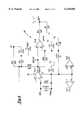
- FIG. 3is a schematic of the controller circuit of the microterminal shown in FIG. 2.
- FIG. 4is a schematic diagram of the connector used to connect the switches of the microterminal to its control circuit.
- FIG. 5is a schematic diagram of the infrared receiver of the microterminal shown in FIG. 2.
- FIG. 6is a schematic diagram of the infrared demodulator of the microterminal shown in FIG. 2.
- FIG. 7is a schematic diagram of the infrared transmitter of the microterminal shown in FIG. 2.
- FIG. 8is a schematic diagram of the auxiliary port which can be used to communicate data to the controller of the microterminal shown in FIG. 2.
- FIG. 9is a schematic diagram of the auxiliary memory and timing circuit of the microterminal shown in FIG. 2.
- FIG. 10is a schematic diagram of the circuit used by the controller of the microterminal to generate audible signals.
- FIG. 11is a schematic diagram of the power processing circuit of the microterminal shown in FIG. 2.
- FIG. 12is a schematic diagram of the circuit used to control the contrast of the LCD display of the microterminal shown in FIG. 2.
- FIG. 13is a schematic diagram of the LCD display connection of the microterminal shown in FIG. 2.
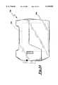
- FIG. 14is a schematic diagram showing an inner container having a microterminal attached thereto, and an outer container having an identification device attached thereto.
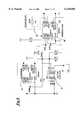
- FIG. 15is a block diagram showing the communication paths between the outside container tracking device, the inside container tracking device and the central controller.
- FIG. 1is intended to show the arrangement of various hardware components of a typical installation of the present invention. Such an installation is described in further detail in U.S. Pat. No. 5,742,238.
- local area network 1is established using Ethernet Ten-Base-T wiring. Attached to the local area network is a file server 2, a CIM (computer integrated manufacturing) terminal 3, a number of client application computers 4, one or more computers 5 configured to control processing equipment within the factory, and a system controller 6.
- Wired to the system controller 6can be one or more optical character readers 7, one or more bar code readers 8, and a plurality of infrared transceivers (IRTs) 9.
- the IRTs 9are mounted in the ceiling of the factory or on one of the processing tools 10.
- the systemalso includes a number of microterminals 12. Given this arrangement, messages can be sent through the system controller 6 and IRTs 9 to the microterminals 12 from the server 2, any of the client applications 4 (through the server 2), or the CIM terminal 3 attached to the local area network 1 (through the server 2).
- FIG. 2shows the exterior of microterminal 12. As shown, it includes a liquid crystal display 20, four push buttons 22, 24, 26 and 28, a beeper 30, and lenses 32, 33 and 34 for the microterminal's IR light generator and detector.
- the design of the microterminal 12allows it to perform many different functions. Its primary purpose is to serve as a portable, wireless, electronic terminal, the use of which allows workers in the factory to communicate with the LAN 1.
- the microterminal 12uses modulated infrared light as a communication medium and is capable of receiving and displaying text and graphic information from the LAN 1 on its display 20.
- the microterminal 12is capable of transmitting information related to its identity and status as well as operator responses entered on one of four push button switches 22-28.
- the microterminal 12is also capable of storing text messages and graphic images and to recall them to the display 20 on operator demand. To attract the operator's attention, the microterminal 12 can also generate audible signals using beeper 30. Still another important function of the microterminal 12 is its ability to provide location information to help operators locate, for example, a container to which the microterminal 12 is attached.
- the microterminal 12includes a CMOS microcontroller 40, a 3.579545 MHZ internal oscillator 42 under resonator control for accurate timing and data generation, and a motion sensor 44.
- the CPUalso has firmware to control all functions and operations of the microterminal.
- FIG. 4shows a jack 46 to which the four membrane switches 22-28 are attached. Jack 46 provides inputs to the microterminal 40 through pins 15-18 of the microcontroller 40 (i.e., PB1-PB4) shown on the left-hand side of the microcontroller in 3.
- PB1-PB4the microcontroller 40
- FIG. 5shows the infrared receiver 50 of the microterminal. It includes three photo detectors 52, a transformer 54, and a differential amplifier 56 which compares the output of the transformer with a known value. Output from the infrared receiver is fed to an infrared demodulator 60 shown in 6. The output of the demodulator circuit is then fed into the microcontroller 40 via the microcontroller's input pin 12 (+RCV).
- the microterminal 12must also be used to transmit infrared signals.
- the transmitter 70receives instructions from the microcontroller 40 via the microcontroller's pin 11 (ENIR).
- ENIRthe microcontroller's pin 11
- the ENIR signal from pin 11opens or closes switch 72 to modulate the output of LEDs 74.
- the microterminalincludes three other RAM memories 80, 82 and 84. These are shown in FIG. 9.
- Memory 80is referred to as time base RAM because the information stored therein is principally used for timing and execution of the instructions contained in the firmware.
- Informationis transmitted between RAM chip 80 and the microcontroller 40 via the microcontroller's pin 30 (RAM1).
- the auxiliary RAM chip 82is provided to store messages to be displayed and the like.
- RAM chip 82communicates with the microcontroller 40 via the microcontroller's pin 29 (RAM2).
- the primary function of RAM memory 84is to store font information for display purposes. It communicates with the microcontroller 40 via the microcontroller's pins 37 (CK) and 40 (DT).
- the beeper 30is also controlled by the microcontroller 40.
- Pin 14 (Beep) of the microcontroller 40is used to send control signals to the beeper causing it to sound. See FIG. 10.
- the power processing circuit 90includes a pair of battery connect wires 90 and 92 and is used to power the LCD display 20, the microcontroller 40, as well as the remaining components of the microterminal.
- the contrast of the LCD display 20is controlled by the circuit 100 shown in FIG. 12.
- the display 20is connected to the microcontroller 20, the LCD contrast control circuit 100 and the power processing circuit 90. This is all done through jack 120 shown in FIG. 13. More specifically, the jack 120 is connected to pins 2-9 (DB0-DB7), 24 (VDISP), 33 (DRST), 36 (R/W), 38 (STB) and 39 (D/I) of microcontroller 40. Pin 3 of jack 120 is connected to the output of LCD contrast control circuit 100 shown in FIG. 12 and power is provided to the display via output VLCD of the power processing circuit 90 shown in FIG. 11.
- the display 20was specifically chosen to reduce energy consumption. Hence, it is a liquid crystal 32 row by 128 column display. It is capable of displaying 21 characters per line.
- the display 20has its own volatile read/write memory and also has a non-volatile serial read/write memory to hold data necessary to translate character codes into display-ready font images. This display also holds some graphic images as well as a variety of text messages which can be displayed.
- the display 20contains a voltage inverter system driven by the microcontroller 40 to generate negative voltage potentials required to activate the LCD pixels.
- the IR receiver 50 of the microterminal 20uses high speed infrared technology to detect and decode 447 kilohertz modulated IR signals at 880 nanometer wavelengths.
- the conical acceptance angle of the IR receiveris 80° from vertical.
- the IR receiveris surrounded by a cover 32 that is 95% transparent to IR energy at 880 nanometer wavelengths. Given this configuration, the IR receiver has a range of approximately 20 feet.
- the microterminal's IR transmitter 70is a current mode, high speed, high efficiency, 880 nanometer IR transmitter.
- the transmitteris pulse modulated at 447 kilohertz by serial data encoded in the pulse position modulation (PPM) format.
- PPMpulse position modulation
- the transmitterhas an 80° radiation angle and generates light energy using three semi-conductor devices 74.
- the user input system of the microterminalincludes four switches 22, 24, 26 and 28. Each of the four switches are momentary contact, conductive rubber push button switches. Each is able to signal the microterminal 20 to generate messages which are then sent to the IRTs 9 through the infrared transmitter 70 of the microterminal 12.
- the microterminal 12provides an audible chirp through beeper 30 with each button press. This chirp is generated by the microterminal 40 and, thus, provides positive user feedback that the signal has been sent.
- the power management system (See FIG. 11) of the microcontroller 40includes two lithium thionyl chloride batteries in an AA cell Form Factor. Each cell has the capacity of 2100 milliampere-hours at nominally 3.6 volts.
- the power management systemincludes circuit protection against a reversal as well as power filtering and power conditioning.
- the microcontroller 40 of the microterminal 12is capable of monitoring battery status so that low battery conditions can be reported to both the display 20 and the factory's central control computer 2. While the batteries of the microterminal 12 are not rechargeable, they are replaceable.
- the microterminal 12includes a unique timing system which is specifically designed to extend battery life.
- the timing systemwhich will be described in further detail below, causes the main processing unit to enter a power-down sleep mode for extended periods of time.
- the timing systemincludes a 32,768 hertz ceramic resonator 86 (see FIG. 9) which activates the microcontroller 40 of the microterminal at pre-defined intervals for routine processing.
- the self-test subsystem of the microterminalperforms basic memory and data checks on power up. It also uses the display 20 to report error conditions. If the display 20 is not operable, a series of beeps can be generated using beeper 30 to report errors. For example, the microterminal 12 will generate two beeps if the first RAM memory 80 is not responding. Three beeps are reported if the first RAM 80 is not returning correct data. If four or five beeps are generated, this is an indication that there is a problem with the second RAM memory 82. Four beeps means that the RAM is not responding at all. Five beeps means that the RAM is not returning correct data. Finally, six beeps indicates a failure in the font RAM 84.
- the operation of the microterminal 12is controlled by firmware placed in the microterminal's microcontroller 40 at the time the microterminal 12 is manufactured. General parameters related to operation of the microterminal 12 will now be described.
- Each microterminal 12is provided with a unique ID number that is stored in non-volatile memory.
- the ID numberis used to uniquely identify the microterminal, to selectively direct data from the system controller 6 to the microterminal 12, to determine the microterminal's location, and is used by the system controller 6 to determine the source of data received from the microterminal.
- these identification numbersare 16 bit allowing 65,535 unique ID numbers to exist in a single system.
- the microterminals 12also have a site code which is used to differentiate microterminals among 256 distinct sites or subsystems, providing 16 million unique microterminal designations.
- the location of the microterminals 12can be effectively tracked because each room or distinct area within the factory is equipped with its own IRT 9.
- the IRTs 9are designed to send out beacons which contain a unique ID number.
- the microterminals 12use the IRT's ID number in the beacon to determine whether the microterminal 12 has been physically moved since it received the last beacon.
- the microterminal 12determines that it has changed locations, it reports to the central control system that it has moved to a new location through an infrared transmission to the IRT 9. Reports by the microterminals 12 are continued in randomized fashion until the central control system acknowledges receipt of the location report.
- the maximum rate for the location reportsis typically once every four seconds for each microterminal.
- each microterminal 12is also capable of communicating with another microterminal.
- the factorycan be equipped with a plurality of pairs of containers 100.
- each pair 100comprises an inner container such as a wafer carrier 102 and an outer container such as a WIP box 104.
- the factorycan also be equipped with a plurality of pairs of microterminals, each pair of microterminals comprising a microterminal 12 attached to the inner container (wafer carrier) of a pair and a second microterminal 12 attached to the outer container (WIP box) of the pair.
- each microterminal 12has a programmable processor (microcontroller 40) having a plurality of memory locations.
- One memory locationtypically located in the non-volatile memory of the unit, is used to store an identification code for that microterminal 12.
- a second memory location(such as in RAM memories 80, 82 or 84 or the onboard memory of the microcontroller 40) can be used to store an identification code for the second microterminal 12 of the pair of microterminals.
- the microterminalscan communicate with each other to determine whether the inner container 102 of a pair of containers is within the outer container 104 of the pair.
- each of the microterminals 12includes a beeper 30 and a display 20.
- the program of the microterminal 12can cause this beeper 30 to be used to issue an audible alarm which is activated if an inner container 102 not paired with the outer container 104 is placed within the outer container 104.
- the programcan also cause display 20 to provide a visual alarm.
- the apparatusincludes a plurality of IRTs, each comprising a transceiver positioned in a separate zone of the workplace and coupled to a central controller for two-way communication between the IRTs and the central controller, there can also be two-way communication between the microterminals 12 and the central controller via the IRTs.
- This two-way communicationpermits the microterminals to send messages to the central controller via the IRTs in the event an inner container 102 not paired with the outer container 104 is positioned within said outer container 104.
- Such messagescan be in the form of an alarm code indicating a mismatch.
- the signalcan include the identity of the inner and outer containers 102 and 104 which are mismatched so that this information is available to the central controller. This capability is schematically represented in FIG. 15.
- central controllercan interrogate the microterminals 12 in a particular zone to ascertain the identity of the containers in said zone. Further, the microterminals can be reprogrammed based upon instructions received from the central controller via the IRTs.
- the two microterminals 12 of a paircan only communicate with each other when there is a detection that the outer container 104 has been closed around the inner container 102.
- the motion sensor 44 of the microterminal 12can be used to detect such a box closure and trigger the microterminal 12 to commence to a communication.
- the microterminal 12can be equipped with a light sensor which causes the microterminal 12 to be activated and commence communication when there is insufficient light. This is particularly useful in connection with microterminals 12 attached to the inner container when the outer container is opaque.
- a containercould be labeled with a machine readable message bearing an identification code. If one container of the pair is labeled in this fashion and the other container is equipped with a microterminal 12 capable of reading this code, then all processing required to determine proper matching of pairs (or to send an alert in the event of a mismatch of pairs of inner and outer containers) can be accomplished using a single microterminal 12.
- microterminal 12would be positioned on the outer container 104 and would read such a label positioned on the inner container 102.
- the microterminal 12can be placed on the inner container 102 if the outer container 104 is designed so that it is transparent to or does not unduly interfere with signals transmitted between the IRTs and microterminal 12.
- Machine-readable codesare well known in the art. One common example is a bar code. When a bar code is used, the microterminal 12 would thus need to be equipped with a bar code reader.
- Still another embodiment of the present inventionwould include the use of a microterminal 12 on one of the containers and an electronic tag on the other container.
- an electronic tagmight be what is referred to in the art as a "dumb tag".
- Such tagsare generally not programmable and have no processing means. However, such tags are capable of transmitting an identification code when interrogated.
- the transmission signal incorporating the codecould be in the form of light pulses, magnetic pulses, R.F. waves or the like.
- the microterminalwould need to be equipped with a receiver capable of reading the identification code transmitted by the dumb tag.
Landscapes
- Physics & Mathematics (AREA)
- General Physics & Mathematics (AREA)
- Engineering & Computer Science (AREA)
- Manufacturing & Machinery (AREA)
- Automation & Control Theory (AREA)
- General Engineering & Computer Science (AREA)
- Quality & Reliability (AREA)
- Condensed Matter Physics & Semiconductors (AREA)
- Computer Hardware Design (AREA)
- Microelectronics & Electronic Packaging (AREA)
- Power Engineering (AREA)
- Container, Conveyance, Adherence, Positioning, Of Wafer (AREA)
Abstract
Description
Claims (28)
Priority Applications (1)
| Application Number | Priority Date | Filing Date | Title |
|---|---|---|---|
| US09/003,542US6138058A (en) | 1998-01-06 | 1998-01-06 | Method for electronically tracking containers to avoid misprocessing of contents |
Applications Claiming Priority (1)
| Application Number | Priority Date | Filing Date | Title |
|---|---|---|---|
| US09/003,542US6138058A (en) | 1998-01-06 | 1998-01-06 | Method for electronically tracking containers to avoid misprocessing of contents |
Publications (1)
| Publication Number | Publication Date |
|---|---|
| US6138058Atrue US6138058A (en) | 2000-10-24 |
Family
ID=21706358
Family Applications (1)
| Application Number | Title | Priority Date | Filing Date |
|---|---|---|---|
| US09/003,542Expired - LifetimeUS6138058A (en) | 1998-01-06 | 1998-01-06 | Method for electronically tracking containers to avoid misprocessing of contents |
Country Status (1)
| Country | Link |
|---|---|
| US (1) | US6138058A (en) |
Cited By (22)
| Publication number | Priority date | Publication date | Assignee | Title |
|---|---|---|---|---|
| WO2003091956A1 (en)* | 2002-04-25 | 2003-11-06 | Hermos Informatik Gmbh | Controlling device for monitoring the spatial or mechanical delimitation of producer goods or materials in the production cycle by using transponder technology |
| US20040008114A1 (en)* | 2002-07-09 | 2004-01-15 | Fred Sawyer | Method and apparatus for tracking objects and people |
| US20040024730A1 (en)* | 2002-08-02 | 2004-02-05 | Brown Thomas M. | Inventory management of products |
| US20040041103A1 (en)* | 2002-08-30 | 2004-03-04 | Canon Kabushiki Kaisha | Positioning apparatus, charged-particle-beam exposure apparatus, and device manufacturing method |
| US20040041709A1 (en)* | 2002-05-23 | 2004-03-04 | Forster Ian J. | Device and method for identifying a containers |
| US20040041714A1 (en)* | 2002-05-07 | 2004-03-04 | Forster Ian J. | RFID temperature device and method |
| US6778088B1 (en)* | 2000-02-11 | 2004-08-17 | Marconi Intellectual Property (Us) Inc. | Deployable identification device |
| US6819968B1 (en)* | 1998-03-04 | 2004-11-16 | Agilent Technologies, Inc. | Apparatus and method for manufacturing integrated circuit devices |
| US20050043850A1 (en)* | 2001-04-09 | 2005-02-24 | John Stevens | Tote-based warehousing system and method |
| US20050096776A1 (en)* | 2003-11-05 | 2005-05-05 | International Business Machines Corporation | Manufacturing product carrier environment and event monitoring system |
| US20050216115A1 (en)* | 2004-03-26 | 2005-09-29 | James You | Transport management system and method thereorf |
| US7328084B1 (en)* | 2004-03-27 | 2008-02-05 | Translogic Corporation | System and method for carrier identification in a pneumatic tube system |
| US20090198365A1 (en)* | 2008-02-04 | 2009-08-06 | International Business Machines Corporation | Computer program product, apparatus and system for managing a manual assembly sequence |
| US20090261956A1 (en)* | 2008-04-16 | 2009-10-22 | RFID Mexico, S.A. DE C.V. | Rfid network system |
| US20100094451A1 (en)* | 2008-10-09 | 2010-04-15 | Translogic Corporation | Pneumatic transport delivery control |
| US20100111617A1 (en)* | 2008-10-09 | 2010-05-06 | Translogic Corporation | Air valve pneumatic tube carrier system |
| US20100221074A1 (en)* | 2008-10-09 | 2010-09-02 | Translogic Corporation | Variable diameter pneumatic tube brake |
| US9139383B2 (en) | 2012-09-13 | 2015-09-22 | Translogic Corporation | Control of pneumatic carrier system based on carrier or payload identification |
| US9439996B2 (en) | 2014-02-28 | 2016-09-13 | Translogic Corporation | Light source disinfection in a pneumatic transport system |
| US9650214B2 (en) | 2013-03-15 | 2017-05-16 | Translogic Corporation | Multiple carrier handling in a pneumatic transport system |
| US10399197B2 (en) | 2017-12-08 | 2019-09-03 | Industrial Technology Research Institute | Method for confirming cutting tool's location and machine system using the same |
| EP3665116A4 (en)* | 2018-07-25 | 2020-12-02 | Slingmax Technologies LLC | SYSTEM AND PROCEDURE FOR LOAD MONITORING OF BUILDING EQUIPMENT |
Citations (46)
| Publication number | Priority date | Publication date | Assignee | Title |
|---|---|---|---|---|
| US3745569A (en)* | 1971-07-22 | 1973-07-10 | Raytheon Co | Remotely powered transponder |
| US3812328A (en)* | 1972-05-31 | 1974-05-21 | Pitney Bowes Inc | Credit card |
| US3852755A (en)* | 1971-07-22 | 1974-12-03 | Raytheon Co | Remotely powered transponder having a dipole antenna array |
| US4068232A (en)* | 1976-02-12 | 1978-01-10 | Fairchild Industries, Inc. | Passive encoding microwave transponder |
| US4570058A (en)* | 1983-10-03 | 1986-02-11 | At&T Technologies, Inc. | Method and apparatus for automatically handling and identifying semiconductor wafers |
| US4600630A (en)* | 1983-09-28 | 1986-07-15 | Rca Corporation | Method for making a protective coating on a machine-readable marking and the product thereof |
| US4611380A (en)* | 1982-12-28 | 1986-09-16 | Nissan Motor Company, Limited | Assembly line manufacturing control apparatus |
| US4636634A (en)* | 1984-08-28 | 1987-01-13 | Veeco Integrated Automation, Inc. | Apparatus with intelligent bins indicating the presence and identity of stored coded articles |
| US4642017A (en)* | 1982-09-30 | 1987-02-10 | Amca International Corporation | Automated in-process pipe storage and retrieval system |
| US4656463A (en)* | 1983-04-21 | 1987-04-07 | Intelli-Tech Corporation | LIMIS systems, devices and methods |
| US4670295A (en)* | 1983-09-28 | 1987-06-02 | Rca Corporation | Method for making a protective coating on a machine-readable marking |
| US4724427A (en)* | 1986-07-18 | 1988-02-09 | B. I. Incorporated | Transponder device |
| US4734698A (en)* | 1985-10-31 | 1988-03-29 | X-Cyte, Inc. | Passive interrogator label system having offset compensation and temperature compensation for a surface acoustic wave transponder |
| US4775786A (en)* | 1986-03-03 | 1988-10-04 | Daiken Kagaku Kogyo Kabushiki Kaisha | Bar code label |
| US4786907A (en)* | 1986-07-14 | 1988-11-22 | Amtech Corporation | Transponder useful in a system for identifying objects |
| US4814742A (en)* | 1985-04-04 | 1989-03-21 | Sekisui Jushi Kabushiki Kaisha | Inquiry system for detecting a selected object |
| US4827395A (en)* | 1983-04-21 | 1989-05-02 | Intelli-Tech Corporation | Manufacturing monitoring and control systems |
| US4827110A (en)* | 1987-06-11 | 1989-05-02 | Fluoroware, Inc. | Method and apparatus for monitoring the location of wafer disks |
| US4833306A (en)* | 1988-05-18 | 1989-05-23 | Fluoroware, Inc. | Bar code remote recognition system for process carriers of wafer disks |
| US4837568A (en)* | 1987-07-08 | 1989-06-06 | Snaper Alvin A | Remote access personnel identification and tracking system |
| US4843640A (en)* | 1986-04-24 | 1989-06-27 | Gte Valeron Corporation | Industrial identification transponder |
| US4857893A (en)* | 1986-07-18 | 1989-08-15 | Bi Inc. | Single chip transponder device |
| US4862160A (en)* | 1983-12-29 | 1989-08-29 | Revlon, Inc. | Item identification tag for rapid inventory data acquisition system |
| US4941201A (en)* | 1985-01-13 | 1990-07-10 | Abbott Laboratories | Electronic data storage and retrieval apparatus and method |
| US4962466A (en)* | 1987-03-27 | 1990-10-09 | Viscom Systems, Inc. | Electronic product information display system |
| US4974166A (en)* | 1987-05-18 | 1990-11-27 | Asyst Technologies, Inc. | Processing systems with intelligent article tracking |
| US4990892A (en)* | 1989-08-07 | 1991-02-05 | Westcom, A Division Of Westside Communications Of Jacksonville, Inc. | Personnel locator system |
| US5005125A (en)* | 1986-02-28 | 1991-04-02 | Sensormatic Electronics Corporation | Surveillance, pricing and inventory system |
| US5050106A (en)* | 1987-10-07 | 1991-09-17 | Omron Tateisi Electronics Co. | Article recognizing system |
| US5097421A (en)* | 1984-12-24 | 1992-03-17 | Asyst Technologies, Inc. | Intelligent waxer carrier |
| US5119104A (en)* | 1990-05-04 | 1992-06-02 | Heller Alan C | Location system adapted for use in multipath environments |
| US5146207A (en)* | 1991-07-01 | 1992-09-08 | Bi, Incorporated | Secure field monitoring device for use in electronic house arrest monitoring system |
| US5153842A (en)* | 1990-02-05 | 1992-10-06 | Pitney Bowes Inc. | Integrated circuit package label and/or manifest system |
| US5204986A (en)* | 1988-02-25 | 1993-04-20 | Kabushiki Kaisha Toahiba | Battery powered radio devices having a battery saving function |
| US5262885A (en)* | 1989-04-18 | 1993-11-16 | U.S. Philips Corporation | Control circuit and data transmission device provided with such a circuit |
| US5266925A (en)* | 1991-09-30 | 1993-11-30 | Westinghouse Electric Corp. | Electronic identification tag interrogation method |
| US5276496A (en)* | 1992-10-30 | 1994-01-04 | Precision Tracking Fm, Inc. | Optical receiver for area location system |
| US5327115A (en)* | 1992-07-29 | 1994-07-05 | Remi Swierczek | Programmable document clip |
| US5339074A (en)* | 1991-09-13 | 1994-08-16 | Fluoroware, Inc. | Very low frequency tracking system |
| US5387993A (en)* | 1993-06-25 | 1995-02-07 | Precision Tracking Fm, Inc. | Method for receiving and transmitting optical data and control information to and from remotely located receivers and transmitters in an optical locator system |
| US5389769A (en)* | 1992-03-27 | 1995-02-14 | Shinko Electric Co., Ltd. | ID recognizing system in semiconductor manufacturing system |
| US5572195A (en)* | 1994-08-01 | 1996-11-05 | Precision Tracking Fm, Inc. | Sensory and control system for local area networks |
| US5742238A (en)* | 1995-09-01 | 1998-04-21 | Emtrak, Inc. | System for communication between a central controller and items in a factory using infrared light |
| US5768140A (en)* | 1996-06-21 | 1998-06-16 | Symbol Technologies, Inc. | RF-interrogatable processing system |
| US5774876A (en)* | 1996-06-26 | 1998-06-30 | Par Government Systems Corporation | Managing assets with active electronic tags |
| US5887176A (en)* | 1996-06-28 | 1999-03-23 | Randtec, Inc. | Method and system for remote monitoring and tracking of inventory |
- 1998
- 1998-01-06USUS09/003,542patent/US6138058A/ennot_activeExpired - Lifetime
Patent Citations (48)
| Publication number | Priority date | Publication date | Assignee | Title |
|---|---|---|---|---|
| US3745569A (en)* | 1971-07-22 | 1973-07-10 | Raytheon Co | Remotely powered transponder |
| US3852755A (en)* | 1971-07-22 | 1974-12-03 | Raytheon Co | Remotely powered transponder having a dipole antenna array |
| US3812328A (en)* | 1972-05-31 | 1974-05-21 | Pitney Bowes Inc | Credit card |
| US4068232A (en)* | 1976-02-12 | 1978-01-10 | Fairchild Industries, Inc. | Passive encoding microwave transponder |
| US4642017A (en)* | 1982-09-30 | 1987-02-10 | Amca International Corporation | Automated in-process pipe storage and retrieval system |
| US4611380A (en)* | 1982-12-28 | 1986-09-16 | Nissan Motor Company, Limited | Assembly line manufacturing control apparatus |
| US4827395A (en)* | 1983-04-21 | 1989-05-02 | Intelli-Tech Corporation | Manufacturing monitoring and control systems |
| US4656463A (en)* | 1983-04-21 | 1987-04-07 | Intelli-Tech Corporation | LIMIS systems, devices and methods |
| US4600630A (en)* | 1983-09-28 | 1986-07-15 | Rca Corporation | Method for making a protective coating on a machine-readable marking and the product thereof |
| US4670295A (en)* | 1983-09-28 | 1987-06-02 | Rca Corporation | Method for making a protective coating on a machine-readable marking |
| US4570058A (en)* | 1983-10-03 | 1986-02-11 | At&T Technologies, Inc. | Method and apparatus for automatically handling and identifying semiconductor wafers |
| US4862160A (en)* | 1983-12-29 | 1989-08-29 | Revlon, Inc. | Item identification tag for rapid inventory data acquisition system |
| US4636634A (en)* | 1984-08-28 | 1987-01-13 | Veeco Integrated Automation, Inc. | Apparatus with intelligent bins indicating the presence and identity of stored coded articles |
| US5097421A (en)* | 1984-12-24 | 1992-03-17 | Asyst Technologies, Inc. | Intelligent waxer carrier |
| US4941201A (en)* | 1985-01-13 | 1990-07-10 | Abbott Laboratories | Electronic data storage and retrieval apparatus and method |
| US4814742A (en)* | 1985-04-04 | 1989-03-21 | Sekisui Jushi Kabushiki Kaisha | Inquiry system for detecting a selected object |
| US4734698A (en)* | 1985-10-31 | 1988-03-29 | X-Cyte, Inc. | Passive interrogator label system having offset compensation and temperature compensation for a surface acoustic wave transponder |
| US5005125A (en)* | 1986-02-28 | 1991-04-02 | Sensormatic Electronics Corporation | Surveillance, pricing and inventory system |
| US4775786A (en)* | 1986-03-03 | 1988-10-04 | Daiken Kagaku Kogyo Kabushiki Kaisha | Bar code label |
| US4843640A (en)* | 1986-04-24 | 1989-06-27 | Gte Valeron Corporation | Industrial identification transponder |
| US4786907A (en)* | 1986-07-14 | 1988-11-22 | Amtech Corporation | Transponder useful in a system for identifying objects |
| US4724427A (en)* | 1986-07-18 | 1988-02-09 | B. I. Incorporated | Transponder device |
| US4857893A (en)* | 1986-07-18 | 1989-08-15 | Bi Inc. | Single chip transponder device |
| US4962466A (en)* | 1987-03-27 | 1990-10-09 | Viscom Systems, Inc. | Electronic product information display system |
| US4974166A (en)* | 1987-05-18 | 1990-11-27 | Asyst Technologies, Inc. | Processing systems with intelligent article tracking |
| US4888473A (en)* | 1987-06-11 | 1989-12-19 | Fluoroware, Inc. | Wafer disk location monitoring system and tagged process carriers for use therewith |
| US4827110A (en)* | 1987-06-11 | 1989-05-02 | Fluoroware, Inc. | Method and apparatus for monitoring the location of wafer disks |
| US4888473B1 (en)* | 1987-06-11 | 1996-10-15 | Fluoroware Inc | Wafer disk location monitoring system and tagged process carrier for use therewith |
| US4837568A (en)* | 1987-07-08 | 1989-06-06 | Snaper Alvin A | Remote access personnel identification and tracking system |
| US5050106A (en)* | 1987-10-07 | 1991-09-17 | Omron Tateisi Electronics Co. | Article recognizing system |
| US5204986A (en)* | 1988-02-25 | 1993-04-20 | Kabushiki Kaisha Toahiba | Battery powered radio devices having a battery saving function |
| US4833306A (en)* | 1988-05-18 | 1989-05-23 | Fluoroware, Inc. | Bar code remote recognition system for process carriers of wafer disks |
| US5262885A (en)* | 1989-04-18 | 1993-11-16 | U.S. Philips Corporation | Control circuit and data transmission device provided with such a circuit |
| US4990892A (en)* | 1989-08-07 | 1991-02-05 | Westcom, A Division Of Westside Communications Of Jacksonville, Inc. | Personnel locator system |
| US5153842A (en)* | 1990-02-05 | 1992-10-06 | Pitney Bowes Inc. | Integrated circuit package label and/or manifest system |
| US5119104A (en)* | 1990-05-04 | 1992-06-02 | Heller Alan C | Location system adapted for use in multipath environments |
| US5146207A (en)* | 1991-07-01 | 1992-09-08 | Bi, Incorporated | Secure field monitoring device for use in electronic house arrest monitoring system |
| US5339074A (en)* | 1991-09-13 | 1994-08-16 | Fluoroware, Inc. | Very low frequency tracking system |
| US5266925A (en)* | 1991-09-30 | 1993-11-30 | Westinghouse Electric Corp. | Electronic identification tag interrogation method |
| US5389769A (en)* | 1992-03-27 | 1995-02-14 | Shinko Electric Co., Ltd. | ID recognizing system in semiconductor manufacturing system |
| US5327115A (en)* | 1992-07-29 | 1994-07-05 | Remi Swierczek | Programmable document clip |
| US5276496A (en)* | 1992-10-30 | 1994-01-04 | Precision Tracking Fm, Inc. | Optical receiver for area location system |
| US5387993A (en)* | 1993-06-25 | 1995-02-07 | Precision Tracking Fm, Inc. | Method for receiving and transmitting optical data and control information to and from remotely located receivers and transmitters in an optical locator system |
| US5572195A (en)* | 1994-08-01 | 1996-11-05 | Precision Tracking Fm, Inc. | Sensory and control system for local area networks |
| US5742238A (en)* | 1995-09-01 | 1998-04-21 | Emtrak, Inc. | System for communication between a central controller and items in a factory using infrared light |
| US5768140A (en)* | 1996-06-21 | 1998-06-16 | Symbol Technologies, Inc. | RF-interrogatable processing system |
| US5774876A (en)* | 1996-06-26 | 1998-06-30 | Par Government Systems Corporation | Managing assets with active electronic tags |
| US5887176A (en)* | 1996-06-28 | 1999-03-23 | Randtec, Inc. | Method and system for remote monitoring and tracking of inventory |
Cited By (57)
| Publication number | Priority date | Publication date | Assignee | Title |
|---|---|---|---|---|
| US6819968B1 (en)* | 1998-03-04 | 2004-11-16 | Agilent Technologies, Inc. | Apparatus and method for manufacturing integrated circuit devices |
| US6778088B1 (en)* | 2000-02-11 | 2004-08-17 | Marconi Intellectual Property (Us) Inc. | Deployable identification device |
| US20050043850A1 (en)* | 2001-04-09 | 2005-02-24 | John Stevens | Tote-based warehousing system and method |
| JP2005524155A (en)* | 2002-04-25 | 2005-08-11 | ヘルモス インフォルマティーク ゲーエムベーハー | Access management method and apparatus, and mobility management method |
| WO2003091956A1 (en)* | 2002-04-25 | 2003-11-06 | Hermos Informatik Gmbh | Controlling device for monitoring the spatial or mechanical delimitation of producer goods or materials in the production cycle by using transponder technology |
| US20040041714A1 (en)* | 2002-05-07 | 2004-03-04 | Forster Ian J. | RFID temperature device and method |
| US6847912B2 (en) | 2002-05-07 | 2005-01-25 | Marconi Intellectual Property (Us) Inc. | RFID temperature device and method |
| US7855637B2 (en) | 2002-05-23 | 2010-12-21 | Forster Ian J | Device and method for identifying a container |
| US7224273B2 (en) | 2002-05-23 | 2007-05-29 | Forster Ian J | Device and method for identifying a container |
| US20070103295A1 (en)* | 2002-05-23 | 2007-05-10 | Mineral Lassen Llc | Device and method for identifying a container |
| US20040041709A1 (en)* | 2002-05-23 | 2004-03-04 | Forster Ian J. | Device and method for identifying a containers |
| US10152620B2 (en) | 2002-07-09 | 2018-12-11 | Automated Tracking Solutions, Llc | Method and apparatus for tracking objects and people |
| US8896449B2 (en) | 2002-07-09 | 2014-11-25 | Automated Tracking Solutions, Llc | Method and apparatus for tracking objects and people |
| US6933849B2 (en) | 2002-07-09 | 2005-08-23 | Fred Sawyer | Method and apparatus for tracking objects and people |
| US7834765B2 (en) | 2002-07-09 | 2010-11-16 | Automated Tracking Solutions, Llc | Method and apparatus for tracking objects and people |
| US10496859B2 (en) | 2002-07-09 | 2019-12-03 | Automated Tracking Solutions, Llc | Method and apparatus for tracking objects and people |
| US9619679B2 (en) | 2002-07-09 | 2017-04-11 | Automated Tracking Solutions, Llc | Method and apparatus for tracking objects and people |
| US20070085681A1 (en)* | 2002-07-09 | 2007-04-19 | Fred Sawyer | Method and apparatus for tracking objects and people |
| US7834766B2 (en) | 2002-07-09 | 2010-11-16 | Automated Tracking Solutions, Llc | Method and apparatus for tracking objects and people |
| US20040008114A1 (en)* | 2002-07-09 | 2004-01-15 | Fred Sawyer | Method and apparatus for tracking objects and people |
| US8279069B2 (en) | 2002-07-09 | 2012-10-02 | Automated Tracking Solutions, Llc | Method and apparatus for tracking objects and people |
| US8866615B2 (en) | 2002-07-09 | 2014-10-21 | Automated Tracking Solutions, Llc | Method and apparatus for tracking objects and people |
| US7551089B2 (en) | 2002-07-09 | 2009-06-23 | Automated Tracking Solutions, Llc | Method and apparatus for tracking objects and people |
| US8842013B2 (en) | 2002-07-09 | 2014-09-23 | Automated Tracking Solutions, Llc | Method and apparatus for tracking objects and people |
| US8742929B2 (en) | 2002-07-09 | 2014-06-03 | Automated Tracking Solutions, Llc | Method and apparatus for tracking objects and people |
| US20090278686A1 (en)* | 2002-07-09 | 2009-11-12 | Frederick Sawyer | Method and apparatus for tracking objects and people |
| US20090295582A1 (en)* | 2002-07-09 | 2009-12-03 | Frederick Sawyer | Method and apparatus for tracking objects and people |
| US20040024730A1 (en)* | 2002-08-02 | 2004-02-05 | Brown Thomas M. | Inventory management of products |
| US6917046B2 (en)* | 2002-08-30 | 2005-07-12 | Canon Kabushiki Kaisha | Positioning apparatus, charged-particle-beam exposure apparatus, and device manufacturing method |
| US20040041103A1 (en)* | 2002-08-30 | 2004-03-04 | Canon Kabushiki Kaisha | Positioning apparatus, charged-particle-beam exposure apparatus, and device manufacturing method |
| US6993405B2 (en) | 2003-11-05 | 2006-01-31 | International Business Machines Corporation | Manufacturing product carrier environment and event monitoring system |
| US20050096776A1 (en)* | 2003-11-05 | 2005-05-05 | International Business Machines Corporation | Manufacturing product carrier environment and event monitoring system |
| US20050216115A1 (en)* | 2004-03-26 | 2005-09-29 | James You | Transport management system and method thereorf |
| US7151980B2 (en)* | 2004-03-26 | 2006-12-19 | Taiwan Semiconductor Manufacturing Co., Ltd. | Transport management system and method thereof |
| US9221626B2 (en) | 2004-03-27 | 2015-12-29 | Translogic Corporation | System and method for carrier identification in a pneumatic tube system |
| US20110186630A1 (en)* | 2004-03-27 | 2011-08-04 | Translogic Corporation | System and method for carrier identification in a pneumatic tube system |
| US7953515B2 (en)* | 2004-03-27 | 2011-05-31 | Translogic Corporation | System and method for carrier identification in a pneumatic tube system |
| US20080180225A1 (en)* | 2004-03-27 | 2008-07-31 | Kenneth Michael Hoganson | System and method for carrier identification in a pneumatic tube system |
| US8447427B2 (en) | 2004-03-27 | 2013-05-21 | Translogic Corporation | System and method for carrier identification in a pneumatic tube system |
| US7328084B1 (en)* | 2004-03-27 | 2008-02-05 | Translogic Corporation | System and method for carrier identification in a pneumatic tube system |
| US8417364B2 (en) | 2008-02-04 | 2013-04-09 | International Business Machines Corporation | Computer program product, apparatus and system for managing a manual assembly sequence |
| US20090198365A1 (en)* | 2008-02-04 | 2009-08-06 | International Business Machines Corporation | Computer program product, apparatus and system for managing a manual assembly sequence |
| US8410911B2 (en)* | 2008-04-16 | 2013-04-02 | RFID Mexico, S.A. DE C.V. | RFID network system |
| US20090261956A1 (en)* | 2008-04-16 | 2009-10-22 | RFID Mexico, S.A. DE C.V. | Rfid network system |
| US8382401B2 (en) | 2008-10-09 | 2013-02-26 | Translogic Corporation | Variable diameter pneumatic tube brake |
| US8793014B2 (en) | 2008-10-09 | 2014-07-29 | Translogic Corporation | Pneumatic transport delivery control |
| US20100221074A1 (en)* | 2008-10-09 | 2010-09-02 | Translogic Corporation | Variable diameter pneumatic tube brake |
| US9292823B2 (en) | 2008-10-09 | 2016-03-22 | Translogic Corporation | Pneumatic transport delivery control |
| US8317432B2 (en) | 2008-10-09 | 2012-11-27 | Translogic Corporation | Air valve pneumatic tube carrier system |
| US20100094451A1 (en)* | 2008-10-09 | 2010-04-15 | Translogic Corporation | Pneumatic transport delivery control |
| US20100111617A1 (en)* | 2008-10-09 | 2010-05-06 | Translogic Corporation | Air valve pneumatic tube carrier system |
| US9139383B2 (en) | 2012-09-13 | 2015-09-22 | Translogic Corporation | Control of pneumatic carrier system based on carrier or payload identification |
| US9656815B2 (en) | 2012-09-13 | 2017-05-23 | Translogic Corporation | Control of pneumatic carrier system based on carrier or payload identification |
| US9650214B2 (en) | 2013-03-15 | 2017-05-16 | Translogic Corporation | Multiple carrier handling in a pneumatic transport system |
| US9439996B2 (en) | 2014-02-28 | 2016-09-13 | Translogic Corporation | Light source disinfection in a pneumatic transport system |
| US10399197B2 (en) | 2017-12-08 | 2019-09-03 | Industrial Technology Research Institute | Method for confirming cutting tool's location and machine system using the same |
| EP3665116A4 (en)* | 2018-07-25 | 2020-12-02 | Slingmax Technologies LLC | SYSTEM AND PROCEDURE FOR LOAD MONITORING OF BUILDING EQUIPMENT |
Similar Documents
| Publication | Publication Date | Title |
|---|---|---|
| US6138058A (en) | Method for electronically tracking containers to avoid misprocessing of contents | |
| US5742238A (en) | System for communication between a central controller and items in a factory using infrared light | |
| US10971265B2 (en) | Tags for automated location and monitoring of moveable objects and related systems | |
| CN111539668B (en) | Warehousing system based on radio frequency technology and control method | |
| CA2058692C (en) | Object identification system for warehouses or supermarkets or personnel or suchlike | |
| KR960014830B1 (en) | Very low frequency tracking system | |
| US7082344B2 (en) | Real time total asset visibility system | |
| US6804578B1 (en) | Real time total asset visibility system | |
| US6700493B1 (en) | Method, apparatus and system for tracking, locating and monitoring an object or individual | |
| EP0382797B1 (en) | Bar code remote recognition system for process carriers of wafer disks | |
| US5005125A (en) | Surveillance, pricing and inventory system | |
| US7564357B2 (en) | Wireless tracking system and method with optical tag removal detection | |
| US5910776A (en) | Method and apparatus for identifying locating or monitoring equipment or other objects | |
| US6182497B1 (en) | Gas detection system and method | |
| US7576650B1 (en) | Real time total asset visibility system | |
| CN104574012A (en) | Logistics storage monitoring system based on UHF intelligent sensor tag | |
| US7207486B1 (en) | Combined optical and radio frequency tag reader | |
| US20240339205A1 (en) | Smart-port multifunctional reader/identifier in a prodcut-sterilisation cycle | |
| GB2277850A (en) | Intelligent radio frequency transponder system | |
| EP1546824A1 (en) | Real time total asset visibility system | |
| CN214376590U (en) | An RFID-based logistics warehouse management system | |
| CN203204780U (en) | Personnel monitoring system for kindergarten | |
| CN109886381A (en) | The RFID Cold chain label of monitoring temperature is carried out to vaccine | |
| CN213877016U (en) | Intelligent control system for lead seal | |
| CN106503763A (en) | A kind of intelligent warehousing system and application based on Internet of Things |
Legal Events
| Date | Code | Title | Description |
|---|---|---|---|
| AS | Assignment | Owner name:JENOPTIK INFAB, INC., COLORADO Free format text:ASSIGNMENT OF ASSIGNORS INTEREST;ASSIGNORS:VAN ANTWERP, KENNETH D., JR.;HARDEE, BEDFORD E.;MYERS, DENNIS L.;REEL/FRAME:011018/0790 Effective date:19971231 | |
| STCF | Information on status: patent grant | Free format text:PATENTED CASE | |
| FEPP | Fee payment procedure | Free format text:PAYOR NUMBER ASSIGNED (ORIGINAL EVENT CODE: ASPN); ENTITY STATUS OF PATENT OWNER: LARGE ENTITY | |
| FPAY | Fee payment | Year of fee payment:4 | |
| FPAY | Fee payment | Year of fee payment:8 | |
| REMI | Maintenance fee reminder mailed | ||
| FEPP | Fee payment procedure | Free format text:PAYER NUMBER DE-ASSIGNED (ORIGINAL EVENT CODE: RMPN); ENTITY STATUS OF PATENT OWNER: LARGE ENTITY Free format text:PAYOR NUMBER ASSIGNED (ORIGINAL EVENT CODE: ASPN); ENTITY STATUS OF PATENT OWNER: LARGE ENTITY | |
| FPAY | Fee payment | Year of fee payment:12 | |
| AS | Assignment | Owner name:WELLS FARGO BANK, NATIONAL ASSOCIATION, MASSACHUSETTS Free format text:SECURITY AGREEMENT;ASSIGNORS:BROOKS AUTOMATION, INC.;BIOSTORAGE TECHNOLOGIES;REEL/FRAME:038891/0765 Effective date:20160526 Owner name:WELLS FARGO BANK, NATIONAL ASSOCIATION, MASSACHUSE Free format text:SECURITY AGREEMENT;ASSIGNORS:BROOKS AUTOMATION, INC.;BIOSTORAGE TECHNOLOGIES;REEL/FRAME:038891/0765 Effective date:20160526 | |
| AS | Assignment | Owner name:MORGAN STANLEY SENIOR FUNDING, INC., MARYLAND Free format text:SECURITY INTEREST;ASSIGNORS:BROOKS AUTOMATION, INC.;BIOSTORAGE TECHNOLOGIES, INC.;REEL/FRAME:044142/0258 Effective date:20171004 | |
| AS | Assignment | Owner name:BROOKS AUTOMATION US, LLC, MASSACHUSETTS Free format text:ASSIGNMENT OF ASSIGNORS INTEREST;ASSIGNOR:BROOKS AUTOMATION HOLDING, LLC;REEL/FRAME:058482/0001 Effective date:20211001 Owner name:BROOKS AUTOMATION HOLDING, LLC, MASSACHUSETTS Free format text:ASSIGNMENT OF ASSIGNORS INTEREST;ASSIGNOR:BROOKS AUTOMATION,INC;REEL/FRAME:058481/0740 Effective date:20211001 |