US6137866A - Indoor XDSL splitter assembly - Google Patents
Indoor XDSL splitter assemblyDownload PDFInfo
- Publication number
- US6137866A US6137866AUS09/085,657US8565798AUS6137866AUS 6137866 AUS6137866 AUS 6137866AUS 8565798 AUS8565798 AUS 8565798AUS 6137866 AUS6137866 AUS 6137866A
- Authority
- US
- United States
- Prior art keywords
- signal
- pair
- terminations
- jack
- housing
- Prior art date
- Legal status (The legal status is an assumption and is not a legal conclusion. Google has not performed a legal analysis and makes no representation as to the accuracy of the status listed.)
- Expired - Lifetime
Links
- 238000000034methodMethods0.000claimsabstractdescription11
- 238000009434installationMethods0.000claimsdescription15
- 238000007789sealingMethods0.000claimsdescription2
- 230000013011matingEffects0.000description3
- 238000010586diagramMethods0.000description2
- 239000002184metalSubstances0.000description2
- 238000012986modificationMethods0.000description2
- 230000004048modificationEffects0.000description2
- 238000006467substitution reactionMethods0.000description2
- 238000007792additionMethods0.000description1
- 230000000712assemblyEffects0.000description1
- 238000000429assemblyMethods0.000description1
- 230000009286beneficial effectEffects0.000description1
- 230000005540biological transmissionEffects0.000description1
- 238000006073displacement reactionMethods0.000description1
- 238000005516engineering processMethods0.000description1
- 238000009413insulationMethods0.000description1
- 238000004806packaging method and processMethods0.000description1
- 238000004382pottingMethods0.000description1
- 238000010079rubber tappingMethods0.000description1
- 230000011664signalingEffects0.000description1
- 125000006850spacer groupChemical group0.000description1
Images


Classifications
- H—ELECTRICITY
- H04—ELECTRIC COMMUNICATION TECHNIQUE
- H04M—TELEPHONIC COMMUNICATION
- H04M11/00—Telephonic communication systems specially adapted for combination with other electrical systems
- H04M11/06—Simultaneous speech and data transmission, e.g. telegraphic transmission over the same conductors
- H04M11/062—Simultaneous speech and data transmission, e.g. telegraphic transmission over the same conductors using different frequency bands for speech and other data
- H—ELECTRICITY
- H04—ELECTRIC COMMUNICATION TECHNIQUE
- H04Q—SELECTING
- H04Q1/00—Details of selecting apparatus or arrangements
- H04Q1/02—Constructional details
- H04Q1/028—Subscriber network interface devices
- H—ELECTRICITY
- H04—ELECTRIC COMMUNICATION TECHNIQUE
- H04Q—SELECTING
- H04Q2201/00—Constructional details of selecting arrangements
- H04Q2201/10—Housing details
- H—ELECTRICITY
- H04—ELECTRIC COMMUNICATION TECHNIQUE
- H04Q—SELECTING
- H04Q2201/00—Constructional details of selecting arrangements
- H04Q2201/80—Constructional details of selecting arrangements in specific systems
- H04Q2201/802—Constructional details of selecting arrangements in specific systems in data transmission systems
Definitions
- the present inventionrelates to an indoor xDSL assembly with an xDSL splitter circuit that is interconnectable with existing indoor telephone installations to split a first signal, for example a telephone signal, from a combined signal transmitted over one outside wire pair.
- ADSLAsymmetric Digital Subscriber Line
- VDSLPlain Old Telephone Service
- IDSLis a variation wherein the multimedia and/or high speed data is transmitted concurrently with an ISDN signal instead of the POTS signal.
- the ISDN signalwhile at a higher frequency than the POTS signal, is at a lower frequency than the multimedia or high speed data signal.
- first signal and second signalwill be used herein to refer generically to at least two different frequency signals transmitted concurrently over twisted-pair wiring that are intended to be separated, or split, at the subscriber.
- combined signalswill be used to refer to both the first and second signals combined over a line.
- An xDSL architectureconnects an xDSL modem on each end of a twisted-pair telephone line, that is, at the "central office" (or node or remote terminal) and at the premises of the subscriber (or customer).
- the terms "splitting” or “splitter”are used to refer to a circuit or component, for example, a low pass filter or low pass and high pass filter combination, that separates the first signal from a combined signal, in the example of a low pass filter, and that separates both the first and second signals from the combined signal in the example of the low pass and high pass filter combination. Components other than low pass and high pass filters may exist or be developed that also perform this splitting function.
- the particular structure and nature of the various splitter circuits or componentsare not necessary to the present invention other than the fact that they "split" the combined signal and are interconnected into an xDSL network in some manner at the customer end of the network.
- Existing inside, or premises, wiring installationstypically comprise two twisted wire pairs routed throughout the premises ("red/green” and “yellow/black”) with typically only the red/green actually wired to the various wall jacks in the home.
- an "indoor is NID”is used that appears generally like a common wall jack face and faceplate but additionally includes a demarcation plug and jack.
- U.S. Pat. Nos. 4,488,008, 4,647,725 and Des. No. 275,667show examples of indoor NIDs that are specifically designed for use indoors to mount in a wall and appear somewhat like a telephone outlet face plate. Indoor NIDs are especially appropriate for use in apartment buildings and other locations where protection is provided in Building Entrance Terminals.
- a splitter sold by Alcatel under the designation "A1000 ADSL Remote Splitter”is disclosed as being installed in an outdoor NID.
- This splitterhas a wire pair pigtail for being connected to the wire pair carrying the combined signal and two pairs of screw terminals for connection to two wire pairs, each carrying a respective one of the first or second signals from the splitter.
- the Alcatel splitteris not readily used indoors by itself in that hard wiring of the pigtail and screw terminals is a cumbersome process and it is not apparent how the splitter would be interconnected with existing indoor telephone wiring installations or how the splitter would be protected from casual contact or physical damage.
- One aspect of the present inventionis a premises signal splitter assembly for receiving a combined telecommunications signal of at least a first signal and a second signal and adapted for mounting within a premises.
- the assemblycomprises a housing adapted for being mounted within the premises.
- the housinghas an exposed surface that is visible when the housing is mounted and a back portion that is not visible when the housing is mounted.
- the housingdefines an interior.
- the assemblyfurther comprises first, a second and a third pair of electrical terminations. The first pair of electrical terminations is adapted to receive the combined telecommunications signal.
- a splitter circuit cardis mounted in the interior of the housing and carries a first splitter circuit electrically connected in series between the first pair of terminations and the second pair of terminations to pass only the first signal of the combined signal from the first pair of terminations to the second pair of terminations.
- the third pair of terminationsis electrically connected to a branch point between the first pair of terminations and the first splitter circuit.
- a first signal jackextends through the exposed surface of the housing, and the first signal jack is electrically connected to the second pair of terminations.
- the premises signal splitter assemblyfurther comprises a build-out assembly adapted for mounting in combination with a premises NID.
- Another aspect of the present inventionis a method of incorporating an xDSL splitter into a premises telephone wiring installation having a first wire pair for carrying a combined signal of at least a first signal and a second signal.
- a signal splitter assemblyis mounted within the premises.
- the splitter assemblycomprises a housing having an exposed surface that is visible when the assembly is mounted and a back portion that is not visible when the assembly is mounted.
- the housingdefines an interior.
- a first, a second and a third pair of electrical terminationsare associated with the housing and a splitter circuit card is mounted in the interior of the housing and carries a first splitter circuit electrically connected in series between the first pair of terminations and the second pair of terminations to pass only the first signal of the combined signal from the first pair of terminations to the second pair of terminations.
- the third pair of terminationsis electrically connected to a branch point between the first pair of terminations and the first splitter circuit.
- a first signal jackextends through the exposed surface of the housing and is electrically connected to the second pair of terminations. Further according to the method, the first wire pair is connected to the first pair of terminations and a telecommunications plug is inserted into the first signal jack.
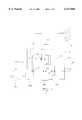
- FIG. 1is a general schematic of a premises signal splitter assembly of the present invention
- FIG. 2is an exploded perspective view of a first embodiment of a premises signal splitter assembly of the present invention
- FIG. 3is a view/wiring diagram of the assembly of FIG. 2;
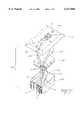
- FIG. 4Ais a perspective view of a conventional premises NID.
- FIG. 4Bis a perspective view of a third embodiment of a premises signal splitter assembly of the present invention shown with the premises NID of FIG. 4A.
- FIG. 4Cis a perspective view of devices in FIG. 4B after assembly.
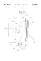
- FIG. 5is a perspective view of a second embodiment of a premises signal splitter assembly of the present invention.
- FIG. 6is an exploded perspective view from the rear of the assembly of FIG. 5;
- the present inventionrelates to a wall mountable assembly that contains a splitter circuit that is readily interconnected with premises telephone wiring.
- the premises wiringhas a first wire pairs that carries a combined telecommunications signal of at least a first and a second signal.
- FIG. 1a generic schematic diagram of assembly 10 is shown that is incorporated in various embodiments of the present invention that will be described herein.
- Assembly 10has housing 15 that is adapted for being mounted to wall 12 (or other surface in a premises), for example, by screws or other suitable fastening mechanism.
- housing 15has an exposed surface that is visible when the housing is mounted and a back portion that is not visible when the housing is mounted.
- Housing 15has carried thereon first pair of electrical terminations 17, second pair of electrical terminations 19 and third pair of electrical terminations 21.
- Splitter circuit card 23is mounted in the interior 20 of housing 15 and has first splitter circuit 62 electrically connected in series between first pair of terminations 17 and second pair of terminations 19.
- first pair of terminations 17is connected in some manner to the first wire pair of the premises telephone wiring.
- Two examplesare shown in phantom in FIG. 1: one example is by connecting first pair of terminations 17 to combined signal jack 34a mounted in housing 15 and extending through the exposed surface of the housing.
- First wire pair 52comprises a telephone wire jumper 94 connected between combined signal jack 34a and an existing telephone wall jack.
- housing 15define hole 26 through which the first wire pair 52 can be routed and connected to first pair of terminations 17 (See FIG. 3).
- first pair of terminations 17connected to a telephone plug that extends from a short pigtail from housing 15 and that can be connected to an existing wall jack when housing 15 is either mounted close to the existing wall jack or over the existing wall jack. Longer mounting screws or bolts can be used to mount housing 15 over an existing wall jack and thereby reduce the number of visible wall mounted outlets in a premises.
- First signal jack 34bis mounted on housing 15, extends through the of housing 15 and is electrically connected to second pair of terminations 19.
- the first signalmay be the POTS signal and first signal jack 34b can be a standard RJ-11 jack to provide a readily usable connection point for the subscriber to connect its telephone with the POTS signal after it is split from the combined signal.
- second pair of terminations 19may be accessed by the subscriber by means of the other connections described above for first pair of terminations 17.
- Third pair of terminations 21is electrically connected to branch point 64 between first pair of terminations 17 and first splitter circuit 62. Branch point 64 could also be at first pair of terminations 17.
- second signal jack 34cmay also be mounted in housing 15 and extend through the exposed surface of the housing for ready access by the subscriber. The second signal may be a data signal for a computer in the premises and second signal jack 34c can be a readily used RJ-45 (or RJ-11, RJ-14, etc.) jack.
- third pair of terminations 21may by hard wired directly to the desired point by wires 54, or otherwise as described above for first pair of terminations 17.
- a second splitter circuit 76can be added to circuit card 23 to pass only the second signal from first pair of terminations 17 to third pair of terminations 21.
- multiple wire pairsmay be wired to one or more of first, second and third pairs of terminations 17, 19, 21 depending on the desired wiring scheme for a given premises wiring installation.
- multiple wire pairsmay be terminated at second pair of terminations 19 in addition to first signal jack 34b and routed through hole 26 and throughout the premises to various POTS wall jacks around the premises.
- This generic arrangement and variations and additionscan be incorporated in various mountable assemblies.
- Assembly 10for mounting on wall 12 (or other surface in a premises) preferably near existing telephone wall jack 13 and faceplate 14 shown in part.
- Assembly 10has housing 15 which is two pieces in this embodiment comprising base 16 and cover 18 that fits over base 16 to define interior 20.
- Housing 15has back portion 58 that is not visible when housing 15 is mounted to wall 12 comprising in this embodiment back surface 22 of base 16.
- Back surface 22is disposed against wall 12 when module 10 is mounted to wall 12.
- Base 16also has inside surface 24 opposite back surface 22.
- Base 16defines holes 26 therethrough to allow passage of wires from wall 12 into interior 20.
- breakouts formed in side walls 38 of cover 18may be provided to enable routing of wires for surface wiring as opposed to in-wall wiring through holes 26.
- Cover 18is attached to base 16 by screws 84 that extend through screw holes 44 in cover 18 and into cover posts 46 extending from base 16. Screws 84 preferably screw into pre-tapped metal inserts mounted in the cover posts 46 for ease of assembly (or screws 84 may self tap into posts 46). A customer option is to use spacers with screws 84 such that heads 85 of screws 84 are spaced above the front face of exposed surface 36. As such, screws 84 can receive a wall mountable phone hung thereon if desired. Any other suitable attachment means may be used for attaching cover 18 to base 16, for example, screws, snap fit structures, sliding engagement structures, hinged attachment, etc. Base 16 is mounted to wall 12 by an appropriate fastener through mounting holes 50.
- Base 16has jack mounting locations 30a,b, c each of which are defined by jack supports 32a, b, c, respectively extending vertically from inside surface 24 of base 16 which are dimensioned to slidably receive jacks 34a,b, c, respectively.
- Housing 15has an exposed surface that is visible when housing 15 is mounted to wall 12 comprising in this embodiment exposed surface 36 of cover 18.
- Cover 18has side walls 38 extending generally vertically from periphery 40. Side walls 38 have free edge 42 which is preferably located over base 16 and against wall 12 upon attachment of cover 18 to base 16.
- Exposed surface 36 of cover 18defines screw holes 44 which align over cover posts 46 extending from base 16 to allow for mounting of cover 18 to base 16.
- Mounting holes 50 protruding through base 16allow base 16 (and assembly 10) to be mounted to wall 12 or a standard electrical box (not shown) pre-installed into wall 12, or otherwise mounted within a premises.
- Cut-outs 48are located to provide an opening for each of the jacks 34a,b, and c so that they are accessible from the exterior of module 10 to have plugs inserted and removed therefrom.
- Jacks 34a, 34b, and 34ceach have cavities 35a, 35b and 35c opening outward in a direction parallel with wall 12.
- Cut-outs 48may include break-outs 49 removal during installation.
- Splitter module 60is located in interior 20 defined by base 16 and cover 18. Module 60 has flanges 61 with notches 63 that are snap engaged by latch arms 28 extending from base 16. Splitter module 60 also has flange 61 with mounting holes 86 spaced to be located over mounting posts 88 extending from base 16. Splitter module 60 has splitter circuit card 23 mounted therein with first splitter circuit 62 which may comprise a low pass filter. First splitter circuit 62 is connected in series between first contacts 67 (which double as branch points 64 in this embodiment) and second contacts 69. First terminations 17 and combined signal jack 34a are connected to first contacts 67. Second terminations 19 and first signal jack 34b are connected to second contacts 69.
- First splitter circuit 62is designed to pass only first signals from first contacts 67 to second contacts 69 when a combined signal is transmitted to first contacts 67.
- Splitter module 60can also include second splitter circuit 76, which may comprise a high pass filter, connected in series between branch points 64 and third contacts 71.
- Third terminations 21 and second signal jack 34care connected to third contacts 71 so as to pass only the second signal from branch points 64 to third contacts 71 when a combined signal is transmitted to branch points 64.
- jacks 34a,b,ccould be connected directly to terminations 17, 19, 21, respectively, as shown in FIG. 1 instead of via contacts 67, 69, 71 respectively, on circuit card 23.
- first wire pair 52 in the premises wiring installation that is to carry the combined signalis connected to first contacts 67 by inserting first plug 96 of jumper 94 into wall jack 13 shown with faceplate 14 and inserting second plug 98 into combined signal jack 34a. If it is desired to route combined signal wiring from assembly 10 to other locations in the premises, wire pairs can be connected to first terminations 17 as desired. As an alternative, first wire pair 52 is not extended by jumper 94 but instead is routed through hole 26 to first pair of terminations 17. As such, combined signal jack 34a may not be used. Additional wiring can still be connected to first pair of terminations 17 because the preferred terminations can have multiple pairs of wires connected thereto.
- First, second and third pairs of terminations 17, 19, 21may comprise self tapping screws that screw into a respective one of a plurality of terminal posts 82 or pre-tapped metal inserts mounted therein.
- One commercial example of such a terminalis referred to as a SEMS assembly (thread forming screws with captive washers).
- First signal jack 34bis available for the subscriber to connect equipment that receives the first signal, for example, a telephone to receive a POTS signal. If it is desired to wire additional first-signal-only jacks in the premises from assembly 10, additional wire pairs can be connected to second terminations 19 and routed as desired.
- the embodiment of FIGS. 2-3additionally includes additional second terminations 19a electrically connected to second terminations 19 by shorting bars 100 to provide additional wire connection capacity.
- Second signal jack 34cis available for the subscriber to connect equipment that receives the second signal, for example, a computer to receive a data signal. If it is desired to wire additional second-signal-only jacks in the premises from assembly 10, additional wires can be connected to third terminations 21 and routed as desired.
- the location and orientation of jacks 34a,b,c and the location of terminations 17,19,21can be rearranged to accommodate different shapes and sizes of splitter modules 60.
- the Alcatel splitter referenced in the Background of the Invention sectioncould be incorporated into assembly 10 as splitter module 60.
- Assembly 110is designed to be flush mounted with wall 12 in a fashion similar to a conventional telephone wall jack and faceplate assembly.
- Assembly 110has housing 128, 120, 112 which is multi-piece in this embodiment, with an exposed surface that comprises in this embodiment front surface 114 of faceplate 112 that is similar in size to a conventional faceplate.
- Faceplate 112has back surface 115 opposite front surface 114.
- Faceplate 112has mounting holes 116 and opening 118 therethrough. Mounting holes 116 on faceplate 112 are sized and spaced to allow mounting of faceplate 112 to a standard electrical enclosure.
- Assembly 110has jack plate 120 that is mounted to back surface 115 of faceplate 112 and has mating portion 122 that is sized to extend into opening 118.
- First signal jack 34b' and second signal jack 34c'are mounted in mating portion 122.
- Mating portion 122includes jack supports 32b' and 32c' in cavities 35b' and 35c' opening outward in a direction perpendicular to wall 12 when assembly 110 is mounted to wall 12.
- Jacks 34b' and 34c'have rear sides 37b' and 37c' opposite cavities 35b' and 35c' and are connected to splitter module 60' via lead pairs 219 and 221.
- Assembly 110has open box 128 with open side 130 that attaches to jack plate 120 to be closed by jack plate 120 to create a housing defining an interior 20'.
- Jack supports 32b' and 32c', and rear sides 37b' and 37c' of jacks 34b' and 34c'extend into interior 20'.
- Box 128has tabs 132 that engage windows 134 on edges 136 of jack plate 120.
- Splitter module 60'is mounted in interior 20' of housing 15' which comprises at least jack plate 120 and box 128. Box 128 is sized to be received in standard electrical enclosure. First, second and third pairs of terminations 17', 19', 21' are located on the exterior of box 128 and connected to splitter module 60' via lead pairs 117, 119 and 121 that travel along grooves 139 on the exterior of box 128 and pass through notches 239 at open side 130 to enter interior 20'.
- the wiring of terminations 17', 19', 21' and jacks 34a', 34b', 34c' to splitter module 60'is the same as the wiring of the embodiment of FIGS. 1-2 and alternatively may be configured like the generic schematic of FIG. 1. Similarly to the description above with respect to FIG.
- termination 17'provides a connection for terminating the wire carrying the combined telecommunications signal from the public network or other source
- terminations 19' and 21'allow additional premises wiring to be terminated to the first signal and second signal for routing throughout the premises.
- Box 128 and jackplate 120may be advantageously designed to enable potting or sealing the electronics and/or electrical connections against moisture.
- cavity 35c' and jack 34c'are recessed from front surface 114 of faceplace 112. This configuration allows jack 34c' to be accessed by a plug whose lead cord is disposed in channel 200. In this manner, a the plug mounted on the back of wall mount telephone may access jack 34b' while the telephone is mounted at mounting holes 116 similarly to the wall mounting described above with respect to screws 84 having heads 85 (FIG. 2).
- FIGS. 4A, 4B and 4CA third embodiment of the present invention is depicted in FIGS. 4A, 4B and 4C.
- a "build-out" assemblyis provided for installation with an existing premises NID, preferably without disturbing the wiring of the existing NID. It is especially beneficial for premises NIDs wired from the back of the unit inside a wall or other surface.
- FIG. 4Adepicts a conventional premises NID 300 comprising cover 314 connected to base 320, and including subscriber jack 313, demarcation jack 301 with demarcation plug 302 inserted therein. Plug 302 is attached to demarcation line cord 303.
- Indoor NID 300is connected to first wire pair 52, which typically extends from a standard electrical enclosure (not shown).
- base 320includes mounting holes 350 for mounting to a wall or other surface in a premises, and base 320 and cover 314 include cooperating means (not shown) for attaching cover 314 to base 320 (e.g., snap fitting tabs and slots).
- cover 314may include cover holes corresponding to receptacles (not shown) in base 320 to allow for screw-on installation.
- FIGS. 4B and 4Cdepict the build-out assembly 315 in combination with conventional premises NID 300.
- Build-out assembly 315contains splitter circuitry similar to that shown with respect to the first and second embodiments, and is adapted to be mounted by screws through holes 344 (one not shown) to a wall or other surface inside a premises.
- Build-out assembly 315includes first signal jack 334b and second signal jack 334c, as well as loop plug 317 attached to line cord 318, all extending through the exposed surface of the assembly housing for connection as hereinafter described.
- the combinationis installed as follows. Premises NID 300 is removed from its mounting in the premises (for example, to a wall) and excess length of wire pair 52 is uncoiled from below the mounting. This excess length is inserted into clearance channel 390 of build-out assembly 315 while wire pair 52 remains connected to premises NID 300. Premises NID 300 is then positioned over build-out assembly 315 and both are then positioned over the original mounting location of premises NID 300 and the combination is mounted to a wall or other surface through mounting holes 350 and holes 344. Cover 314 is removed from base 320 during installation.
- Demarcation plug 302 of premises NID 300is inserted in first signal jack 334b of build-out assembly 315.
- Loop plug 317 of build-out assembly 315is inserted in demarcation jack 301.
- a combined signal transmitted across wire pair 52may be connected through premises NID 300 to build-out assembly 315 through demarcation jack 301 to loop plug 317.
- a second signal, or combined signal, depending on the splitter circuitryis accessible through second signal jack 334c by second signal plug 381 attached to second signal line cord 382, which is in turn connected to equipment that receives the second signal, for example, a computer to receive a data signal.
- a first signalis accessible through subscriber jack 313 which is electrically connected to demarcation plug 302 which is plugged into first signal jack 334b.
- the demarcation functionmay be carried out by the subscriber either before or after the splitter circuitry, through demarcation jack 301 and first signal jack 334b, respectively.
- the demarcation functionmay also be carried out by the subscriber for the second signal through second signal jack 334c.
- Second signal terminations 321may be located on the cover of build-out assembly 315 (as depicted in phantom in FIG. 4B) for use instead of second signal jack 334c. These terminations may preferably comprise screw terminals.
Landscapes
- Engineering & Computer Science (AREA)
- Computer Networks & Wireless Communication (AREA)
- Signal Processing (AREA)
- Structure Of Telephone Exchanges (AREA)
- Telephonic Communication Services (AREA)
Abstract
Description
Claims (29)
Priority Applications (4)
| Application Number | Priority Date | Filing Date | Title |
|---|---|---|---|
| US09/085,657US6137866A (en) | 1998-05-28 | 1998-05-28 | Indoor XDSL splitter assembly |
| CA002272233ACA2272233A1 (en) | 1998-05-28 | 1999-05-18 | Indoor xdsl splitter assembly |
| EP99304148AEP0966147A3 (en) | 1998-05-28 | 1999-05-27 | Indoor XDSL splitter assembly |
| US29/117,970USD455331S1 (en) | 1998-05-28 | 2000-01-31 | Face plate |
Applications Claiming Priority (1)
| Application Number | Priority Date | Filing Date | Title |
|---|---|---|---|
| US09/085,657US6137866A (en) | 1998-05-28 | 1998-05-28 | Indoor XDSL splitter assembly |
Related Child Applications (1)
| Application Number | Title | Priority Date | Filing Date |
|---|---|---|---|
| US29/117,970Continuation-In-PartUSD455331S1 (en) | 1998-05-28 | 2000-01-31 | Face plate |
Publications (1)
| Publication Number | Publication Date |
|---|---|
| US6137866Atrue US6137866A (en) | 2000-10-24 |
Family
ID=22193099
Family Applications (1)
| Application Number | Title | Priority Date | Filing Date |
|---|---|---|---|
| US09/085,657Expired - LifetimeUS6137866A (en) | 1998-05-28 | 1998-05-28 | Indoor XDSL splitter assembly |
Country Status (3)
| Country | Link |
|---|---|
| US (1) | US6137866A (en) |
| EP (1) | EP0966147A3 (en) |
| CA (1) | CA2272233A1 (en) |
Cited By (41)
| Publication number | Priority date | Publication date | Assignee | Title |
|---|---|---|---|---|
| USD448347S1 (en) | 1999-09-30 | 2001-09-25 | Harris Corporation | Telephone signal splitter |
| US20020003802A1 (en)* | 2000-07-06 | 2002-01-10 | Il-Kyong Kim | Method for providing high-speed data service and voice service |
| US20020044646A1 (en)* | 2000-08-11 | 2002-04-18 | Keenum John A. | Tool-less wall-mount distributed filter housing |
| US6404347B1 (en)* | 2001-05-04 | 2002-06-11 | Excelsus Technologies, Inc. | Alarm filter circuit |
| USD461453S1 (en) | 2001-09-28 | 2002-08-13 | Atech Technology Co. Ltd. | Splitter |
| US20030042991A1 (en)* | 2001-03-12 | 2003-03-06 | Glen Cotant | Advanced electronic signal conditioning assembly and method |
| WO2003056800A1 (en)* | 2001-12-26 | 2003-07-10 | Allied Telesis Kabushiki Kaisha | Vdsl system |
| US20040022013A1 (en)* | 2000-06-16 | 2004-02-05 | Stefan Badura | Distribution device in a data signal processing installation, and data signal processing installation |
| US6731750B1 (en)* | 1998-10-30 | 2004-05-04 | Teraforce Technology Corporation | xDSL multiple-point interface device |
| US6804353B2 (en)* | 2001-06-29 | 2004-10-12 | Adc Telecommunications, Inc. | Splitter assembly with high density backplane board |
| US6804352B2 (en)* | 2001-06-29 | 2004-10-12 | Adc Telecommunications, Inc. | High circuit density pots splitter assembly |
| US20040242081A1 (en)* | 2001-03-16 | 2004-12-02 | Dieter Otto | Terminal block and distribution point |
| US20050023020A1 (en)* | 2002-05-23 | 2005-02-03 | Friedrich Denter | Cover plates for ADSL-splitter positions in modular distribution frames |
| US20050272275A1 (en)* | 2004-06-02 | 2005-12-08 | Graves Alan F | Overlay to permit delivery of telephony and mission-critical data services to hospital-wide points of care |
| US6996232B1 (en)* | 1997-12-31 | 2006-02-07 | Corning Cable Systems Llc | XDSL splitter line module for network interface device |
| US20060039125A1 (en)* | 2004-08-17 | 2006-02-23 | Invensys Building Systems, Inc. | Method and apparatus for progressively connecting a controller to an external circuit of a building |
| US7130417B1 (en)* | 1999-06-21 | 2006-10-31 | Teledex Corporation | Telephone-coupled device for internet access |
| USRE39432E1 (en)* | 1998-11-19 | 2006-12-19 | Pulse Engineering, Inc. | Impedance blocking filter circuit |
| US7257223B2 (en)* | 2001-05-10 | 2007-08-14 | Adc Telecommunications, Inc. | Splitter assembly for a telecommunications system |
| USRE40020E1 (en) | 1998-11-19 | 2008-01-22 | Pulse Engineering, Inc. | Impedance blocking filter circuit |
| US7333606B1 (en)* | 2000-04-13 | 2008-02-19 | Adc Telecommunications, Inc. | Splitter architecture for a telecommunications system |
| US20080165950A1 (en)* | 2007-01-10 | 2008-07-10 | Ko-Jen Chang | Switchable transmission device for VDSL CO/CPE circuit |
| US7463732B1 (en)* | 2000-05-05 | 2008-12-09 | 3Com Corporation | Flexible data outlet |
| US20080304656A1 (en)* | 2007-06-08 | 2008-12-11 | Vernon Reed | Splitter wall plates for digital subscriber line (dsl) communication systems and methods to use the same |
| US7593394B2 (en) | 2000-04-18 | 2009-09-22 | Mosaid Technologies Incorporated | Telephone communication system over a single telephone line |
| US7633966B2 (en) | 2000-04-19 | 2009-12-15 | Mosaid Technologies Incorporated | Network combining wired and non-wired segments |
| USRE41145E1 (en) | 1998-11-19 | 2010-02-23 | Pulse Engineering, Inc. | Impedance blocking filter circuit |
| US7680255B2 (en) | 2001-07-05 | 2010-03-16 | Mosaid Technologies Incorporated | Telephone outlet with packet telephony adaptor, and a network using same |
| US7686653B2 (en) | 2003-09-07 | 2010-03-30 | Mosaid Technologies Incorporated | Modular outlet |
| US7702095B2 (en) | 2003-01-30 | 2010-04-20 | Mosaid Technologies Incorporated | Method and system for providing DC power on local telephone lines |
| US7715534B2 (en) | 2000-03-20 | 2010-05-11 | Mosaid Technologies Incorporated | Telephone outlet for implementing a local area network over telephone lines and a local area network using such outlets |
| US7746905B2 (en) | 2003-03-13 | 2010-06-29 | Mosaid Technologies Incorporated | Private telephone network connected to more than one public network |
| US7756268B2 (en) | 2004-02-16 | 2010-07-13 | Mosaid Technologies Incorporated | Outlet add-on module |
| US7965735B2 (en) | 1998-07-28 | 2011-06-21 | Mosaid Technologies Incorporated | Local area network of serial intelligent cells |
| US7990908B2 (en) | 2002-11-13 | 2011-08-02 | Mosaid Technologies Incorporated | Addressable outlet, and a network using the same |
| US8005206B1 (en) | 2007-03-15 | 2011-08-23 | Bh Electronics, Inc. | VDSL splitter |
| DE102010014352A1 (en)* | 2010-04-09 | 2011-10-13 | S. Siedle & Söhne Telefon- und Telegrafenwerke OHG | Connecting device for electrical connection of inner station of house communication system to connection box, has electrical plug connector with two plug parts and another electrical plug connector with other two plug parts |
| US8351582B2 (en) | 1999-07-20 | 2013-01-08 | Mosaid Technologies Incorporated | Network for telephony and data communication |
| US8582598B2 (en) | 1999-07-07 | 2013-11-12 | Mosaid Technologies Incorporated | Local area network for distributing data communication, sensing and control signals |
| US20140226455A1 (en)* | 2011-09-07 | 2014-08-14 | Commscope, Inc. Of North Carolina | Communications Connectors Having Frequency Dependent Communications Paths and Related Methods |
| US10986165B2 (en) | 2004-01-13 | 2021-04-20 | May Patents Ltd. | Information device |
Families Citing this family (6)
| Publication number | Priority date | Publication date | Assignee | Title |
|---|---|---|---|---|
| US6795552B1 (en) | 1999-12-14 | 2004-09-21 | Corning Cable Systems Llc | Enhanced services network interface device |
| EP1202544A1 (en)* | 2000-10-30 | 2002-05-02 | Telefonaktiebolaget L M Ericsson (Publ) | System and method for distributing voice and data |
| AU2002211175A1 (en)* | 2000-10-30 | 2002-05-15 | Telefonaktiebolaget Lm Ericsson (Publ) | Arrangement and method for providing broadband data communication access and narrowband telecommunication access through a pstn/isdn |
| US7327558B2 (en) | 2002-10-07 | 2008-02-05 | Square D Company | Front-accessible communications port for enclosed electrical equipment |
| FR2896935A1 (en)* | 2006-06-27 | 2007-08-03 | France Telecom | Communication terminal e.g. telephone, and double stranded analog telephone line connecting device for use in internal telephonic service system, has two pins connected to other two pins, respectively, by short-circuit |
| FR3025682B1 (en)* | 2014-09-08 | 2018-03-30 | Nexans | INTERNAL TERMINATION DEVICE |
Citations (5)
| Publication number | Priority date | Publication date | Assignee | Title |
|---|---|---|---|---|
| US5408260A (en)* | 1994-01-11 | 1995-04-18 | Northern Telecom Limited | Customer premises ADSL signal distribution arrangement |
| US5440335A (en)* | 1993-05-28 | 1995-08-08 | U S West Advanced Technologies, Inc. | Method and apparatus for delivering passband and telephony signals in a coaxial cable network |
| US5469495A (en)* | 1993-05-28 | 1995-11-21 | U S West Advanced Technologies, Inc. | Method and apparatus for delivering secured telephone service in hybrid coaxial cable network |
| US5623542A (en)* | 1993-02-16 | 1997-04-22 | Antec Corp. | Combination telephone network interface and cable television apparatus and cable television module |
| US6026160A (en)* | 1997-12-31 | 2000-02-15 | Siecor Operations, Llc | xDSL splitter interconnect module for network interface device |
Family Cites Families (2)
| Publication number | Priority date | Publication date | Assignee | Title |
|---|---|---|---|---|
| US4647725A (en)* | 1985-03-11 | 1987-03-03 | Siecor Corporation | Indoor type telephone network interface device |
| US5757803A (en)* | 1995-11-27 | 1998-05-26 | Analog Devices, Inc. | Pots splitter assembly with improved transhybrid loss for digital subscriber loop transmission |
- 1998
- 1998-05-28USUS09/085,657patent/US6137866A/ennot_activeExpired - Lifetime
- 1999
- 1999-05-18CACA002272233Apatent/CA2272233A1/ennot_activeAbandoned
- 1999-05-27EPEP99304148Apatent/EP0966147A3/ennot_activeWithdrawn
Patent Citations (5)
| Publication number | Priority date | Publication date | Assignee | Title |
|---|---|---|---|---|
| US5623542A (en)* | 1993-02-16 | 1997-04-22 | Antec Corp. | Combination telephone network interface and cable television apparatus and cable television module |
| US5440335A (en)* | 1993-05-28 | 1995-08-08 | U S West Advanced Technologies, Inc. | Method and apparatus for delivering passband and telephony signals in a coaxial cable network |
| US5469495A (en)* | 1993-05-28 | 1995-11-21 | U S West Advanced Technologies, Inc. | Method and apparatus for delivering secured telephone service in hybrid coaxial cable network |
| US5408260A (en)* | 1994-01-11 | 1995-04-18 | Northern Telecom Limited | Customer premises ADSL signal distribution arrangement |
| US6026160A (en)* | 1997-12-31 | 2000-02-15 | Siecor Operations, Llc | xDSL splitter interconnect module for network interface device |
Non-Patent Citations (6)
| Title |
|---|
| A1000 ADSl REmote Spittler (LPFR) installation (with Guideslines for In home Wiring); Alcatel Telecom; A9693; 3EC 15158 AAAA TCZZA Ed. 01.* |
| A1000 ADSl REmote Spittler (LPFR) installation (with Guideslines for In-home Wiring); Alcatel Telecom; A9693; 3EC 15158 AAAA TCZZA-Ed. 01. |
| John Cook and Phil Sheppard, "ADSL and VADSL Splitter Design and Telephony Performance," IEEE Journal on Selected Areas in Communications, vol. 13, NO. 9, p. 1634-1642, Dec. 1995. |
| John Cook and Phil Sheppard, ADSL and VADSL Splitter Design and Telephony Performance, IEEE Journal on Selected Areas in Communications, vol. 13, NO. 9, p. 1634 1642, Dec. 1995.* |
| Marlis Humphrey and John Freeman, "How xDSL Supports Broadband Services to the Home," IEEE Network, vol. 11, No. 1, p. 14-23, 1+2/1997. |
| Marlis Humphrey and John Freeman, How xDSL Supports Broadband Services to the Home, IEEE Network, vol. 11, No. 1, p. 14 23, 1 2/1997.* |
Cited By (90)
| Publication number | Priority date | Publication date | Assignee | Title |
|---|---|---|---|---|
| US6996232B1 (en)* | 1997-12-31 | 2006-02-07 | Corning Cable Systems Llc | XDSL splitter line module for network interface device |
| US7965735B2 (en) | 1998-07-28 | 2011-06-21 | Mosaid Technologies Incorporated | Local area network of serial intelligent cells |
| US8908673B2 (en) | 1998-07-28 | 2014-12-09 | Conversant Intellectual Property Management Incorporated | Local area network of serial intelligent cells |
| US8885659B2 (en) | 1998-07-28 | 2014-11-11 | Conversant Intellectual Property Management Incorporated | Local area network of serial intelligent cells |
| US8885660B2 (en) | 1998-07-28 | 2014-11-11 | Conversant Intellectual Property Management Incorporated | Local area network of serial intelligent cells |
| US8867523B2 (en) | 1998-07-28 | 2014-10-21 | Conversant Intellectual Property Management Incorporated | Local area network of serial intelligent cells |
| US7986708B2 (en) | 1998-07-28 | 2011-07-26 | Mosaid Technologies Incorporated | Local area network of serial intelligent cells |
| US8325636B2 (en) | 1998-07-28 | 2012-12-04 | Mosaid Technologies Incorporated | Local area network of serial intelligent cells |
| US6731750B1 (en)* | 1998-10-30 | 2004-05-04 | Teraforce Technology Corporation | xDSL multiple-point interface device |
| USRE41145E1 (en) | 1998-11-19 | 2010-02-23 | Pulse Engineering, Inc. | Impedance blocking filter circuit |
| USRE44094E1 (en) | 1998-11-19 | 2013-03-19 | Pulse Electronics, Inc. | Impedance blocking filter circuit |
| USRE41164E1 (en)* | 1998-11-19 | 2010-03-16 | Pulse Engineering, Inc. | Impedance blocking filter circuit |
| USRE40020E1 (en) | 1998-11-19 | 2008-01-22 | Pulse Engineering, Inc. | Impedance blocking filter circuit |
| USRE39432E1 (en)* | 1998-11-19 | 2006-12-19 | Pulse Engineering, Inc. | Impedance blocking filter circuit |
| US7130417B1 (en)* | 1999-06-21 | 2006-10-31 | Teledex Corporation | Telephone-coupled device for internet access |
| US8582598B2 (en) | 1999-07-07 | 2013-11-12 | Mosaid Technologies Incorporated | Local area network for distributing data communication, sensing and control signals |
| US8351582B2 (en) | 1999-07-20 | 2013-01-08 | Mosaid Technologies Incorporated | Network for telephony and data communication |
| US8929523B2 (en) | 1999-07-20 | 2015-01-06 | Conversant Intellectual Property Management Inc. | Network for telephony and data communication |
| USD448347S1 (en) | 1999-09-30 | 2001-09-25 | Harris Corporation | Telephone signal splitter |
| US7715534B2 (en) | 2000-03-20 | 2010-05-11 | Mosaid Technologies Incorporated | Telephone outlet for implementing a local area network over telephone lines and a local area network using such outlets |
| US8363797B2 (en) | 2000-03-20 | 2013-01-29 | Mosaid Technologies Incorporated | Telephone outlet for implementing a local area network over telephone lines and a local area network using such outlets |
| US8855277B2 (en) | 2000-03-20 | 2014-10-07 | Conversant Intellectual Property Managment Incorporated | Telephone outlet for implementing a local area network over telephone lines and a local area network using such outlets |
| US20080260142A1 (en)* | 2000-04-13 | 2008-10-23 | Adc Telecommunications, Inc. | Splitter architecture for a telecommunications system |
| US7333606B1 (en)* | 2000-04-13 | 2008-02-19 | Adc Telecommunications, Inc. | Splitter architecture for a telecommunications system |
| US8559422B2 (en) | 2000-04-18 | 2013-10-15 | Mosaid Technologies Incorporated | Telephone communication system over a single telephone line |
| US7593394B2 (en) | 2000-04-18 | 2009-09-22 | Mosaid Technologies Incorporated | Telephone communication system over a single telephone line |
| US8000349B2 (en) | 2000-04-18 | 2011-08-16 | Mosaid Technologies Incorporated | Telephone communication system over a single telephone line |
| US8223800B2 (en) | 2000-04-18 | 2012-07-17 | Mosaid Technologies Incorporated | Telephone communication system over a single telephone line |
| US8982904B2 (en) | 2000-04-19 | 2015-03-17 | Conversant Intellectual Property Management Inc. | Network combining wired and non-wired segments |
| US8982903B2 (en) | 2000-04-19 | 2015-03-17 | Conversant Intellectual Property Management Inc. | Network combining wired and non-wired segments |
| US8873575B2 (en) | 2000-04-19 | 2014-10-28 | Conversant Intellectual Property Management Incorporated | Network combining wired and non-wired segments |
| US8873586B2 (en) | 2000-04-19 | 2014-10-28 | Conversant Intellectual Property Management Incorporated | Network combining wired and non-wired segments |
| US8867506B2 (en) | 2000-04-19 | 2014-10-21 | Conversant Intellectual Property Management Incorporated | Network combining wired and non-wired segments |
| US8848725B2 (en) | 2000-04-19 | 2014-09-30 | Conversant Intellectual Property Management Incorporated | Network combining wired and non-wired segments |
| US7633966B2 (en) | 2000-04-19 | 2009-12-15 | Mosaid Technologies Incorporated | Network combining wired and non-wired segments |
| US7463732B1 (en)* | 2000-05-05 | 2008-12-09 | 3Com Corporation | Flexible data outlet |
| US20040022013A1 (en)* | 2000-06-16 | 2004-02-05 | Stefan Badura | Distribution device in a data signal processing installation, and data signal processing installation |
| US7324632B2 (en) | 2000-06-16 | 2008-01-29 | Ccs Technology Inc. | Distribution device in a data signal processing installation, and data signal processing installation |
| US6970502B2 (en) | 2000-07-06 | 2005-11-29 | Samsung Electronics Co., Ltd. | Method for providing high-speed data service and voice service |
| US20020003802A1 (en)* | 2000-07-06 | 2002-01-10 | Il-Kyong Kim | Method for providing high-speed data service and voice service |
| US20020044646A1 (en)* | 2000-08-11 | 2002-04-18 | Keenum John A. | Tool-less wall-mount distributed filter housing |
| US6904149B2 (en) | 2000-08-11 | 2005-06-07 | Corning Cable Systems Llc | Tool-less wall-mount distributed filter housing |
| US7110931B2 (en) | 2001-03-12 | 2006-09-19 | Pulse Engineering, Inc. | Advanced electronic signal conditioning assembly and method |
| US20030042991A1 (en)* | 2001-03-12 | 2003-03-06 | Glen Cotant | Advanced electronic signal conditioning assembly and method |
| US7018229B2 (en)* | 2001-03-16 | 2006-03-28 | 3M Innovative Properties Company | Terminal block and distribution point |
| US20040242081A1 (en)* | 2001-03-16 | 2004-12-02 | Dieter Otto | Terminal block and distribution point |
| US6404347B1 (en)* | 2001-05-04 | 2002-06-11 | Excelsus Technologies, Inc. | Alarm filter circuit |
| US6472992B1 (en)* | 2001-05-04 | 2002-10-29 | Excelsus Technologies, Inc. | Alarm filter circuit |
| US7257223B2 (en)* | 2001-05-10 | 2007-08-14 | Adc Telecommunications, Inc. | Splitter assembly for a telecommunications system |
| US6804353B2 (en)* | 2001-06-29 | 2004-10-12 | Adc Telecommunications, Inc. | Splitter assembly with high density backplane board |
| US6804352B2 (en)* | 2001-06-29 | 2004-10-12 | Adc Telecommunications, Inc. | High circuit density pots splitter assembly |
| US7769030B2 (en) | 2001-07-05 | 2010-08-03 | Mosaid Technologies Incorporated | Telephone outlet with packet telephony adapter, and a network using same |
| US8472593B2 (en) | 2001-07-05 | 2013-06-25 | Mosaid Technologies Incorporated | Telephone outlet with packet telephony adaptor, and a network using same |
| US7680255B2 (en) | 2001-07-05 | 2010-03-16 | Mosaid Technologies Incorporated | Telephone outlet with packet telephony adaptor, and a network using same |
| US8761186B2 (en) | 2001-07-05 | 2014-06-24 | Conversant Intellectual Property Management Incorporated | Telephone outlet with packet telephony adapter, and a network using same |
| USD461453S1 (en) | 2001-09-28 | 2002-08-13 | Atech Technology Co. Ltd. | Splitter |
| WO2003056800A1 (en)* | 2001-12-26 | 2003-07-10 | Allied Telesis Kabushiki Kaisha | Vdsl system |
| US20050023020A1 (en)* | 2002-05-23 | 2005-02-03 | Friedrich Denter | Cover plates for ADSL-splitter positions in modular distribution frames |
| US7990908B2 (en) | 2002-11-13 | 2011-08-02 | Mosaid Technologies Incorporated | Addressable outlet, and a network using the same |
| US8107618B2 (en) | 2003-01-30 | 2012-01-31 | Mosaid Technologies Incorporated | Method and system for providing DC power on local telephone lines |
| US7702095B2 (en) | 2003-01-30 | 2010-04-20 | Mosaid Technologies Incorporated | Method and system for providing DC power on local telephone lines |
| US8787562B2 (en) | 2003-01-30 | 2014-07-22 | Conversant Intellectual Property Management Inc. | Method and system for providing DC power on local telephone lines |
| US8238328B2 (en) | 2003-03-13 | 2012-08-07 | Mosaid Technologies Incorporated | Telephone system having multiple distinct sources and accessories therefor |
| US7746905B2 (en) | 2003-03-13 | 2010-06-29 | Mosaid Technologies Incorporated | Private telephone network connected to more than one public network |
| US7686653B2 (en) | 2003-09-07 | 2010-03-30 | Mosaid Technologies Incorporated | Modular outlet |
| US10986165B2 (en) | 2004-01-13 | 2021-04-20 | May Patents Ltd. | Information device |
| US10986164B2 (en) | 2004-01-13 | 2021-04-20 | May Patents Ltd. | Information device |
| US11032353B2 (en) | 2004-01-13 | 2021-06-08 | May Patents Ltd. | Information device |
| US11095708B2 (en) | 2004-01-13 | 2021-08-17 | May Patents Ltd. | Information device |
| US8243918B2 (en) | 2004-02-16 | 2012-08-14 | Mosaid Technologies Incorporated | Outlet add-on module |
| US8611528B2 (en)* | 2004-02-16 | 2013-12-17 | Mosaid Technologies Incorporated | Outlet add-on module |
| US8565417B2 (en) | 2004-02-16 | 2013-10-22 | Mosaid Technologies Incorporated | Outlet add-on module |
| US8542819B2 (en)* | 2004-02-16 | 2013-09-24 | Mosaid Technologies Incorporated | Outlet add-on module |
| KR101209504B1 (en) | 2004-02-16 | 2012-12-07 | 모사이드 테크놀로지스 인코퍼레이티드 | Outlet add?on module |
| US7881462B2 (en) | 2004-02-16 | 2011-02-01 | Mosaid Technologies Incorporated | Outlet add-on module |
| US7756268B2 (en) | 2004-02-16 | 2010-07-13 | Mosaid Technologies Incorporated | Outlet add-on module |
| US7220143B2 (en)* | 2004-06-02 | 2007-05-22 | Nortel Networks Limited | Overlay to permit delivery of telephony and mission-critical data services to hospital-wide points of care |
| US20050272275A1 (en)* | 2004-06-02 | 2005-12-08 | Graves Alan F | Overlay to permit delivery of telephony and mission-critical data services to hospital-wide points of care |
| US20060039125A1 (en)* | 2004-08-17 | 2006-02-23 | Invensys Building Systems, Inc. | Method and apparatus for progressively connecting a controller to an external circuit of a building |
| US7515433B2 (en)* | 2004-08-17 | 2009-04-07 | Tac, Llc | Method and apparatus for progressively connecting a controller to an external circuit of a building |
| US20080165950A1 (en)* | 2007-01-10 | 2008-07-10 | Ko-Jen Chang | Switchable transmission device for VDSL CO/CPE circuit |
| US8005206B1 (en) | 2007-03-15 | 2011-08-23 | Bh Electronics, Inc. | VDSL splitter |
| US8422662B2 (en) | 2007-06-08 | 2013-04-16 | At&T Intellectual Property I, L.P. | Splitter wall plates for digital subscriber line (DSL) communication systems and methods to use the same |
| US20100098059A1 (en)* | 2007-06-08 | 2010-04-22 | Vernon Reed | Splitter wall plates for digital subscriber line (dsl) communication systems and methods to use the same |
| US7657023B2 (en) | 2007-06-08 | 2010-02-02 | At&T Intellectual Property I, L.P. | Splitter wall plates for digital subscriber line (DSL) communication systems and methods to use the same |
| US20080304656A1 (en)* | 2007-06-08 | 2008-12-11 | Vernon Reed | Splitter wall plates for digital subscriber line (dsl) communication systems and methods to use the same |
| US8644493B2 (en) | 2007-06-08 | 2014-02-04 | At&T Intellectual Property I, L.P. | Splitter wall plates for digital subscriber line (DSL) communication systems and methods to use the same |
| DE102010014352A1 (en)* | 2010-04-09 | 2011-10-13 | S. Siedle & Söhne Telefon- und Telegrafenwerke OHG | Connecting device for electrical connection of inner station of house communication system to connection box, has electrical plug connector with two plug parts and another electrical plug connector with other two plug parts |
| US9455765B2 (en)* | 2011-09-07 | 2016-09-27 | Commscope, Inc. Of North Carolina | Communications connectors having frequency dependent communications paths and related methods |
| US20140226455A1 (en)* | 2011-09-07 | 2014-08-14 | Commscope, Inc. Of North Carolina | Communications Connectors Having Frequency Dependent Communications Paths and Related Methods |
Also Published As
| Publication number | Publication date |
|---|---|
| EP0966147A2 (en) | 1999-12-22 |
| EP0966147A3 (en) | 2003-11-05 |
| CA2272233A1 (en) | 1999-11-28 |
Similar Documents
| Publication | Publication Date | Title |
|---|---|---|
| US6137866A (en) | Indoor XDSL splitter assembly | |
| US6560334B1 (en) | Telephone subscriber line module | |
| US6026160A (en) | xDSL splitter interconnect module for network interface device | |
| US5599190A (en) | Communication wiring system including a reconfigurable outlet assembly | |
| US5735714A (en) | Information management outlet module and assembly providing protection to exposed cabling | |
| US6033259A (en) | Mounting arrangement for telecommunications equipment | |
| US4494815A (en) | Self-aligning cover for modular tricoupler | |
| US5177782A (en) | Modular protected entrance terminal | |
| KR20040050067A (en) | Front access dsx assembly | |
| US6288334B1 (en) | Electronics module attached to back face of jack plate | |
| US5205758A (en) | Communications distribution interface unit assembly | |
| US6996232B1 (en) | XDSL splitter line module for network interface device | |
| US4700384A (en) | Indoor telephone line demarcation box having several compartments | |
| US6039578A (en) | Network interface device for line testing | |
| US20030048895A1 (en) | Wall phone adapter with removable filter modular units | |
| US6430288B1 (en) | Phone line splitter assembly | |
| US6535579B1 (en) | Network interface device with disconnectable half-ringer | |
| US20020111077A1 (en) | Universal splitter for xDSL modems | |
| US20070047526A1 (en) | Systems and methods for conecting between telecommunications equipment | |
| US6246749B1 (en) | Network interface unit and module | |
| US4753610A (en) | Connectorized terminal block | |
| US6252941B1 (en) | Network interface unit | |
| GB2445212A (en) | Signal treatment device for use with telecommunications equipment | |
| US7499526B2 (en) | Termination module including subscriber bridge having burglar alarm connections | |
| US10187515B2 (en) | Network interface devices having external demarcation points |
Legal Events
| Date | Code | Title | Description |
|---|---|---|---|
| AS | Assignment | Owner name:SIECOR OPERATIONS, LLC, NORTH CAROLINA Free format text:ASSIGNMENT OF ASSIGNORS INTEREST;ASSIGNORS:STABER, HARLEY J.;LANQUIST, TODD C.;KEENUM, JOHN A.;AND OTHERS;REEL/FRAME:009402/0841 Effective date:19980713 | |
| AS | Assignment | Owner name:SIECOR OPERATIONS, LLC, NORTH CAROLINA Free format text:ASSIGNMENT OF ASSIGNORS INTEREST;ASSIGNORS:KEENUM, JOHN A.;LANQUIST, TODD C.;REEL/FRAME:010578/0894;SIGNING DATES FROM 20000126 TO 20000128 | |
| STCF | Information on status: patent grant | Free format text:PATENTED CASE | |
| FPAY | Fee payment | Year of fee payment:4 | |
| FPAY | Fee payment | Year of fee payment:8 | |
| FPAY | Fee payment | Year of fee payment:12 | |
| AS | Assignment | Owner name:CORNING CABLE SYSTEMS LLC, NORTH CAROLINA Free format text:CHANGE OF NAME;ASSIGNOR:SIECOR OPERATIONS, LLC;REEL/FRAME:041988/0926 Effective date:20000524 | |
| AS | Assignment | Owner name:CCS TECHNOLOGY, INC., DELAWARE Free format text:ASSIGNMENT OF ASSIGNORS INTEREST;ASSIGNOR:CORNING CABLE SYSTEMS LLC;REEL/FRAME:042377/0394 Effective date:20030124 | |
| AS | Assignment | Owner name:CORNING OPTICAL COMMUNICATIONS LLC, NORTH CAROLINA Free format text:MERGER;ASSIGNORS:CCS TECHNOLOGY, INC.;CORNING OPTICAL COMMUNICATIONS BRANDS, INC.;REEL/FRAME:043601/0427 Effective date:20170630 |