US6137402A - Method for arming a security system - Google Patents
Method for arming a security systemDownload PDFInfo
- Publication number
- US6137402A US6137402AUS09/261,984US26198499AUS6137402AUS 6137402 AUS6137402 AUS 6137402AUS 26198499 AUS26198499 AUS 26198499AUS 6137402 AUS6137402 AUS 6137402A
- Authority
- US
- United States
- Prior art keywords
- status
- faulted
- sensor
- security system
- receiver
- Prior art date
- Legal status (The legal status is an assumption and is not a legal conclusion. Google has not performed a legal analysis and makes no representation as to the accuracy of the status listed.)
- Expired - Lifetime
Links
- 238000000034methodMethods0.000titleclaimsabstractdescription19
- 239000011521glassSubstances0.000claimsdescription10
- 230000035939shockEffects0.000claimsdescription8
- 238000001514detection methodMethods0.000claims4
- 230000005540biological transmissionEffects0.000description3
- 230000004913activationEffects0.000description1
- 230000001419dependent effectEffects0.000description1
- 238000010586diagramMethods0.000description1
- 238000009434installationMethods0.000description1
- 238000012986modificationMethods0.000description1
- 230000004048modificationEffects0.000description1
- 239000000779smokeSubstances0.000description1
Images

Classifications
- G—PHYSICS
- G08—SIGNALLING
- G08B—SIGNALLING OR CALLING SYSTEMS; ORDER TELEGRAPHS; ALARM SYSTEMS
- G08B25/00—Alarm systems in which the location of the alarm condition is signalled to a central station, e.g. fire or police telegraphic systems
- G08B25/01—Alarm systems in which the location of the alarm condition is signalled to a central station, e.g. fire or police telegraphic systems characterised by the transmission medium
- G08B25/10—Alarm systems in which the location of the alarm condition is signalled to a central station, e.g. fire or police telegraphic systems characterised by the transmission medium using wireless transmission systems
- G—PHYSICS
- G08—SIGNALLING
- G08B—SIGNALLING OR CALLING SYSTEMS; ORDER TELEGRAPHS; ALARM SYSTEMS
- G08B25/00—Alarm systems in which the location of the alarm condition is signalled to a central station, e.g. fire or police telegraphic systems
- G08B25/008—Alarm setting and unsetting, i.e. arming or disarming of the security system
Definitions
- This inventionrelates to wireless security systems that use send-only radio frequency (RF) sensors to indicate a fault condition in the monitored area, and in particular to wireless security systems that cannot be armed when the status signifies a fault condition.
- the fault conditionmay be detected motion, detected glass breakage, etc.
- Many low cost wireless security systemsuse send-only RF sensor transmitters to communicate status to a receiver/control unit.
- the receiver/control unitmonitors the status by receiving and decoding messages.
- the receiver/control unitinitiates an alarm.
- a motion detectortransmits a fault message when motion has been detected and a restore message when the motion has ceased.
- Each messageis generally transmitted a number of times to provide a high probability of receipt by the receiver/control unit.
- the receiver/control unitWhen the receiver/control unit detects a faulted status, it will not allow a user to arm the security system. In order to subsequently arm the security system, someone must re-activate the motion detector that has the faulted status associated with it. This causes a restore message to be transmitted without being interfered with by other transmitted messages, thereby causing the faulted status to be cleared. It may be possible that a number of motion detectors have failed to successfully deliver their restore messages. Each detector that has a fault status associated with it will need to be activated in order to arm the system.
- the present inventionis a method of arming a security system which comprises one or more of the following sensors: motion detectors, glass break detectors, shock sensors, wireless key fobs, and/or panic pendants. All of these sensors send fault messages when they detect a fault condition, and restore messages when the fault condition is cleared. In send-only RF security systems where there may be messages clashing or losses of messages due to memory overflow and where the receiver/controller does not have the capability to poll the sensor for its status, the receiver/controller may maintain a faulted status for one or more of the sensors because of associated lost restore messages.
- the method of the present inventionwhich allows the security system to be armed in spite of a faulted status from a sensor, such as a motion detector, comprises the steps of receiving a request from a keypad to arm the system, determining if a faulted status for a sensor exists in the receiver/controller, if a faulted status does exist, then changing the faulted status to a restored status, and arming the security system when there are no faulted statuses in the receiver/controller.
- the steps of determining if a faulted status exists in the receiver/controller, and if a faulted status does exist, then changing the faulted status to a restored statusmay be repeated for any number of sensors until there is no faulted statuses in the receiver/controller.
- the changing of the faulted statuses to restored statusesis performed by simply changing a variable stored as a memory bit in the receiver/controller.
- the present inventionrecognizes that some sensors, such as door detectors and window detectors, need to be physically examined when a fault condition is indicated. This is because one would-not want to leave the premises while these conditions exist. Therefore the receiver/controller has the ability to processes sensor fault conditions differently dependent on the sensor type, i.e. fault conditions from motion detectors may be disregarded, while fault conditions from door detectors may continue to keep the security system from being armed.
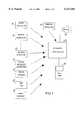
- FIG. 1is a diagram of a security system of the preferred embodiment of the present invention.
- FIG. 2is a flow chart of the operation of the preferred embodiment of the present invention.
- FIG. 1Shown in FIG. 1 are the components of a typical security system 2 comprising receiver/controller 22, keypad 20, window detector 4, door detector 6, motion detectors 8, glass breakage detector 10, shock sensor 12, key fob 14 and panic pendant 16.
- the sensors 4, 6, 8, 10, 12, 14, and 16are send only sensors, transmitting RF messages to the receiver/controller 22.
- the receiver/controller 22receives commands, such as arm or disarm, from the keypad 20.
- the receiver/controller 22processes the messages from the sensors 4, 6, 8, 10, 12, 14, and 16 and when a fault condition has been detected, i.e. glass breakage, the receiver/controller 22 transmits a signal to the siren 18.
- the sensors 4, 6, 8, 10, 12, 14, and 16When the security system 2 is not armed, the sensors 4, 6, 8, 10, 12, 14, and 16 still transmit messages and the receiver/controller 22 still receives and processes the messages, but the siren 18 is not sounded.
- the messages sent by the sensors 4, 6, 8, 10, 12, 14, and 16are transmitted a number of times to provide a high probability of the receiver/controller 22 receiving the messages.
- the sensors 4, 6, 8, 10, 12, 14, and 16typically send supervision messages, fault messages and restore messages to the receiver/controller 22.
- the supervision messagesprovide sensor passive status information
- the fault messagesinform the receiver/controller 22 that motion (or glass breakage, or shock, etc.) has been detected in the area being monitored
- the restore messagesinform the receiver/controller 22 that the motion (or glass breakage, or shock, etc.) has ceased.
- the operation of each of the components of the security system 2is well known to someone skilled in the art and is not described further.
- the receiver/controller 22processes the faulted status from the window detector 4 and the door detector 6 differently than from the motion detectors 8, glass breakage detector 10, the shock sensor 12, the key fob 14, and the panic pendant 16 to ensure that a window or a door is not left open while the system is armed.
- the present inventionaddresses the problem of transmission clash or specifically loss of a restore message from a sensor 8, 10, 12, 14, or 16. This may occur when there are many sensors transmitting messages concurrently.
- the loss of a restore messagecauses the receiver/controller 22 to incorrectly maintain a faulted status for the sensor 8, 10, 12, 14, or 16.
- the loss of a restore messageis not significant if the sensor 8, 10, 12, 14, or 16 is reactivated, causing a second restore message to be transmitted once the motion ceases and allowing the receiver/controller 22 to update the faulted status.
- the loss of the restore messagemay also occur if the memory located in the receiver/controller 22 overflows due to the volume of messages.
- An example of a situation where the loss of the restore message could cause a problemis in a school building.
- the school buildingcontains many motion detectors to monitor the entire site which includes hallways, stairways, and classrooms. During the school day the motion detectors are concurrently activated by many students changing classes at the same time. Concurrent activation also occurs when all of the students exit the building at the end of the school day.
- a security guardattempted to arm the security system at the end of the day (when the building was empty), he was prevented from doing so because the receiver/controller 22 indicated a faulted condition from one or more of the motion detectors due to a loss of its associated restore message.
- the guardwas then forced to reactivate the affected motion detector(s) causing it to transmit a restore message without concurrent sensor transmissions allowing the receiver/controller 22 to update the faulted condition. Once the erroneous faulted condition was deleted, the guard was finally able to arm the security system.
- the security system 2may be armed regardless of missing restore messages from any number of sensors.
- the receiver/controller 22checks if the security system 2 is armed. If it has been, it checks if the message is a request to disarm and if so, it performs the disarm routine. If it is not, the receiver/controller 22 checks if the message is a fault message. If not, the receiver/controller 22 returns to the start of the routine. If it is a fault message, the receiver/controller 22 process the message as an alarm event and waits for a request to disarm. When a request for disarm is received the receiver/controller 22 logs the alarm event, disarms the security system 2, and goes back to the start of the routine.
- the receiver/controller 22checks if the received message is an arm request. If it is not, the routine is started again. If it is a request for arm, the receiver/controller 22 checks if there are any fault conditions. If not, the security system 2 is armed and the routine is restarted.
- the receiver/controller 22checks if there is a fault condition has been caused by one of the sensors that it has been programmed to override (i.e. sensors 8, 10, 12, 14, or 16). If the fault condition is caused by one of the sensors that it has been programmed to override, then the faulted status is overridden (i.e cleared or updated) to a restored status. This may be done for any number of sensors 8, 10, 12, 14, and 16. The subsequent changing of the faulted status to a restored status is performed by changing a variable stored in memory for those sensors. Once the faulted status from the sensors 8, 10, 12, 14, and 16 are cleared, the receiver/controller 22 checks if there are any other fault conditions (i.e. smoke), and if there are the receiver/controller 22 performs the failure to arm routine and restarts. If there are no more faulted statuses, the system is armed and the routine is restarted.
- the fault conditioni.e. sensors 8, 10, 12, 14, or 16
- the faulted statuswas caused by a sensor that the receiver/controller 22 has not been programmed to override, then it will not clear the fault status to a restored status, but must wait for the particular sensor to transmit a restore message. This may occur in the case of a door sensor, where the user attempting to arm the system will have to investigate the area, and close the door to cause it to transmit a restore message and allow the system to be armed.
- the present inventionis disclosed for a send-only RF security system, but may also be used in other types of security systems.
- the security systemmay include other components such as a wireless keypad or a dialer.
- the intent of the present inventionis to ignore incorrect faulted statuses from the motion detectors 8, glass breakage detector 10, the shock sensor 12, the key fob 14, and the panic pendant 16, the present invention may also be used to ignore faulted statuses from the window detector 4 and the door detector 6.
- the flow of operationsmay be performed differently.
Landscapes
- Engineering & Computer Science (AREA)
- Business, Economics & Management (AREA)
- Emergency Management (AREA)
- Physics & Mathematics (AREA)
- General Physics & Mathematics (AREA)
- Computer Networks & Wireless Communication (AREA)
- Computer Security & Cryptography (AREA)
- Alarm Systems (AREA)
Abstract
Description
Claims (16)
Priority Applications (1)
| Application Number | Priority Date | Filing Date | Title |
|---|---|---|---|
| US09/261,984US6137402A (en) | 1999-03-04 | 1999-03-04 | Method for arming a security system |
Applications Claiming Priority (1)
| Application Number | Priority Date | Filing Date | Title |
|---|---|---|---|
| US09/261,984US6137402A (en) | 1999-03-04 | 1999-03-04 | Method for arming a security system |
Publications (1)
| Publication Number | Publication Date |
|---|---|
| US6137402Atrue US6137402A (en) | 2000-10-24 |
Family
ID=22995696
Family Applications (1)
| Application Number | Title | Priority Date | Filing Date |
|---|---|---|---|
| US09/261,984Expired - LifetimeUS6137402A (en) | 1999-03-04 | 1999-03-04 | Method for arming a security system |
Country Status (1)
| Country | Link |
|---|---|
| US (1) | US6137402A (en) |
Cited By (22)
| Publication number | Priority date | Publication date | Assignee | Title |
|---|---|---|---|---|
| US20030067385A1 (en)* | 2001-09-10 | 2003-04-10 | Eric Shank | Motion sensor device |
| US20040150521A1 (en)* | 2003-02-03 | 2004-08-05 | Stilp Louis A. | RFID based security system |
| US20040160324A1 (en)* | 2003-02-03 | 2004-08-19 | Stilp Louis A. | Controller for a security system |
| US20040196153A1 (en)* | 2003-04-07 | 2004-10-07 | Cockburn John Malcolm | Continuous feedback container security system |
| US20040212494A1 (en)* | 2003-02-03 | 2004-10-28 | Stilp Louis A. | Cordless telephone system |
| US20040215750A1 (en)* | 2003-04-28 | 2004-10-28 | Stilp Louis A. | Configuration program for a security system |
| US20040212500A1 (en)* | 2003-02-03 | 2004-10-28 | Stilp Louis A. | RFID based security network |
| US20040212493A1 (en)* | 2003-02-03 | 2004-10-28 | Stilp Louis A. | RFID reader for a security network |
| US20050110635A1 (en)* | 2003-03-20 | 2005-05-26 | Giermanski James R. | System, methods and computer program products for monitoring transport containers |
| US7057512B2 (en) | 2003-02-03 | 2006-06-06 | Ingrid, Inc. | RFID reader for a security system |
| US7079034B2 (en) | 2003-02-03 | 2006-07-18 | Ingrid, Inc. | RFID transponder for a security system |
| US7079020B2 (en) | 2003-02-03 | 2006-07-18 | Ingrid, Inc. | Multi-controller security network |
| US7091827B2 (en) | 2003-02-03 | 2006-08-15 | Ingrid, Inc. | Communications control in a security system |
| US7119658B2 (en) | 2003-02-03 | 2006-10-10 | Ingrid, Inc. | Device enrollment in a security system |
| US20070063841A1 (en)* | 2005-09-22 | 2007-03-22 | Honeywell International, Inc. | Cross-zone supervision for a security system |
| US7283048B2 (en) | 2003-02-03 | 2007-10-16 | Ingrid, Inc. | Multi-level meshed security network |
| US7495544B2 (en) | 2003-02-03 | 2009-02-24 | Ingrid, Inc. | Component diversity in a RFID security network |
| US20090066652A1 (en)* | 2007-09-10 | 2009-03-12 | Verstraelen J G R | Keypad for a security system |
| US7511614B2 (en) | 2003-02-03 | 2009-03-31 | Ingrid, Inc. | Portable telephone in a security network |
| US7532114B2 (en) | 2003-02-03 | 2009-05-12 | Ingrid, Inc. | Fixed part-portable part communications network for a security network |
| US8665084B2 (en) | 2011-07-29 | 2014-03-04 | Adt Us Holdings, Inc. | Security system and method |
| US9520049B2 (en) | 2014-12-30 | 2016-12-13 | Google Inc. | Learned overrides for home security |
Citations (6)
| Publication number | Priority date | Publication date | Assignee | Title |
|---|---|---|---|---|
| US3839711A (en)* | 1970-04-02 | 1974-10-01 | Minnesota Mining & Mfg | Security system and control circuit |
| US4179691A (en)* | 1976-11-15 | 1979-12-18 | Cerberus Ag | Infrared intrusion detector circuit |
| US4232308A (en)* | 1979-06-21 | 1980-11-04 | The Scott & Fetzer Company | Wireless alarm system |
| US4517554A (en)* | 1981-05-26 | 1985-05-14 | Siemens Aktiengesellschaft | Method and apparatus for inspecting a danger alarm system |
| US5677664A (en)* | 1995-10-10 | 1997-10-14 | Jon Snyder, Inc. | Controlling automobile alarm systems |
| US5977871A (en)* | 1997-02-13 | 1999-11-02 | Avr Group Limited | Alarm reporting system |
- 1999
- 1999-03-04USUS09/261,984patent/US6137402A/ennot_activeExpired - Lifetime
Patent Citations (6)
| Publication number | Priority date | Publication date | Assignee | Title |
|---|---|---|---|---|
| US3839711A (en)* | 1970-04-02 | 1974-10-01 | Minnesota Mining & Mfg | Security system and control circuit |
| US4179691A (en)* | 1976-11-15 | 1979-12-18 | Cerberus Ag | Infrared intrusion detector circuit |
| US4232308A (en)* | 1979-06-21 | 1980-11-04 | The Scott & Fetzer Company | Wireless alarm system |
| US4517554A (en)* | 1981-05-26 | 1985-05-14 | Siemens Aktiengesellschaft | Method and apparatus for inspecting a danger alarm system |
| US5677664A (en)* | 1995-10-10 | 1997-10-14 | Jon Snyder, Inc. | Controlling automobile alarm systems |
| US5977871A (en)* | 1997-02-13 | 1999-11-02 | Avr Group Limited | Alarm reporting system |
Cited By (38)
| Publication number | Priority date | Publication date | Assignee | Title |
|---|---|---|---|---|
| US20030067385A1 (en)* | 2001-09-10 | 2003-04-10 | Eric Shank | Motion sensor device |
| US7019639B2 (en) | 2003-02-03 | 2006-03-28 | Ingrid, Inc. | RFID based security network |
| US20040160324A1 (en)* | 2003-02-03 | 2004-08-19 | Stilp Louis A. | Controller for a security system |
| US7532114B2 (en) | 2003-02-03 | 2009-05-12 | Ingrid, Inc. | Fixed part-portable part communications network for a security network |
| US20040212494A1 (en)* | 2003-02-03 | 2004-10-28 | Stilp Louis A. | Cordless telephone system |
| US7511614B2 (en) | 2003-02-03 | 2009-03-31 | Ingrid, Inc. | Portable telephone in a security network |
| US20040212500A1 (en)* | 2003-02-03 | 2004-10-28 | Stilp Louis A. | RFID based security network |
| US20040212493A1 (en)* | 2003-02-03 | 2004-10-28 | Stilp Louis A. | RFID reader for a security network |
| US7495544B2 (en) | 2003-02-03 | 2009-02-24 | Ingrid, Inc. | Component diversity in a RFID security network |
| US7202789B1 (en) | 2003-02-03 | 2007-04-10 | Ingrid, Inc. | Clip for RFID transponder of a security network |
| US20040150521A1 (en)* | 2003-02-03 | 2004-08-05 | Stilp Louis A. | RFID based security system |
| US7053764B2 (en) | 2003-02-03 | 2006-05-30 | Ingrid, Inc. | Controller for a security system |
| US7042353B2 (en) | 2003-02-03 | 2006-05-09 | Ingrid, Inc. | Cordless telephone system |
| US7023341B2 (en) | 2003-02-03 | 2006-04-04 | Ingrid, Inc. | RFID reader for a security network |
| US7057512B2 (en) | 2003-02-03 | 2006-06-06 | Ingrid, Inc. | RFID reader for a security system |
| US7079034B2 (en) | 2003-02-03 | 2006-07-18 | Ingrid, Inc. | RFID transponder for a security system |
| US7079020B2 (en) | 2003-02-03 | 2006-07-18 | Ingrid, Inc. | Multi-controller security network |
| US7084756B2 (en) | 2003-02-03 | 2006-08-01 | Ingrid, Inc. | Communications architecture for a security network |
| US7091827B2 (en) | 2003-02-03 | 2006-08-15 | Ingrid, Inc. | Communications control in a security system |
| US7119658B2 (en) | 2003-02-03 | 2006-10-10 | Ingrid, Inc. | Device enrollment in a security system |
| US7283048B2 (en) | 2003-02-03 | 2007-10-16 | Ingrid, Inc. | Multi-level meshed security network |
| US20050110635A1 (en)* | 2003-03-20 | 2005-05-26 | Giermanski James R. | System, methods and computer program products for monitoring transport containers |
| US7154390B2 (en)* | 2003-03-20 | 2006-12-26 | Powers International, Inc. | System, methods and computer program products for monitoring transport containers |
| US20040196153A1 (en)* | 2003-04-07 | 2004-10-07 | Cockburn John Malcolm | Continuous feedback container security system |
| US6870476B2 (en) | 2003-04-07 | 2005-03-22 | Bulldog Technologies Inc. | Continuous feedback container security system |
| US20040215750A1 (en)* | 2003-04-28 | 2004-10-28 | Stilp Louis A. | Configuration program for a security system |
| WO2007038224A3 (en)* | 2005-09-22 | 2007-07-12 | Honeywell Int Inc | Cross-zone supervision for a security system |
| US7423530B2 (en)* | 2005-09-22 | 2008-09-09 | Honeywell International Inc. | Cross-zone supervision for a security system |
| US20070063841A1 (en)* | 2005-09-22 | 2007-03-22 | Honeywell International, Inc. | Cross-zone supervision for a security system |
| US8059095B2 (en)* | 2007-09-10 | 2011-11-15 | Utc Fire & Security Americas Corporation, Inc. | Keypad for a security system |
| US20090066652A1 (en)* | 2007-09-10 | 2009-03-12 | Verstraelen J G R | Keypad for a security system |
| US8665084B2 (en) | 2011-07-29 | 2014-03-04 | Adt Us Holdings, Inc. | Security system and method |
| US9117349B2 (en) | 2011-07-29 | 2015-08-25 | Adt Us Holdings, Inc. | Security system having segregated operating software |
| US9286772B2 (en) | 2011-07-29 | 2016-03-15 | Adt Us Holdings, Inc. | Security system and method |
| US9589441B2 (en) | 2011-07-29 | 2017-03-07 | Adt Us Holdings, Inc. | Security system and method |
| US9520049B2 (en) | 2014-12-30 | 2016-12-13 | Google Inc. | Learned overrides for home security |
| US9916751B2 (en) | 2014-12-30 | 2018-03-13 | Google Llc | Learned overrides for home security |
| US10223896B2 (en) | 2014-12-30 | 2019-03-05 | Google Llc | Operating a security system |
Similar Documents
| Publication | Publication Date | Title |
|---|---|---|
| US6137402A (en) | Method for arming a security system | |
| US11688274B2 (en) | System and method for alarm signaling during alarm system destruction | |
| US8368532B2 (en) | Security system annunciation communication delay | |
| US7046147B2 (en) | Integrated security system and method | |
| US6868493B2 (en) | System and method for panel linking in a security system | |
| US8525664B2 (en) | System and method for minimizing the amount of data being sent on a network for supervised security systems | |
| US4559526A (en) | Security alarm system | |
| US5907279A (en) | Initialization of a wireless security system | |
| US8274385B2 (en) | Method and apparatus for controlling the timing of an alarm signal in a security system | |
| US6593850B1 (en) | Wireless intrusion detector with test mode | |
| US20080218336A1 (en) | Method and apparatus for providing a message sequence count in a security systems | |
| US6034593A (en) | Communication system and method for keyless-entry alarms | |
| US7733235B2 (en) | Wireless smoke and fire detection system and method | |
| US4847593A (en) | Transmission circuit of fire protection/security system | |
| JP3350601B2 (en) | Multiple transmission type fire alarm system | |
| JP3502943B2 (en) | Intruder detection device | |
| US20060109103A1 (en) | Transmission technique for a portable alarm system | |
| JP2535015B2 (en) | Transmission control method for one-way signal transmission system | |
| JPH0285999A (en) | monitoring device | |
| JPH0612587A (en) | Security wireless system provided with periodical transmission function | |
| JPH0664671B2 (en) | Alarm confirmation device | |
| JPH0520554A (en) | Radio security system |
Legal Events
| Date | Code | Title | Description |
|---|---|---|---|
| AS | Assignment | Owner name:PITTWAY CORPORATION, ILLINOIS Free format text:ASSIGNMENT OF ASSIGNORS INTEREST;ASSIGNOR:MARINO, FRANCIS C.;REEL/FRAME:009806/0776 Effective date:19990303 | |
| STCF | Information on status: patent grant | Free format text:PATENTED CASE | |
| CC | Certificate of correction | ||
| AS | Assignment | Owner name:HONEYWELL INTERNATIONAL INC., NEW JERSEY Free format text:MERGER;ASSIGNOR:PITTWAY CORPORATION;REEL/FRAME:014223/0953 Effective date:20030327 | |
| FEPP | Fee payment procedure | Free format text:PAYOR NUMBER ASSIGNED (ORIGINAL EVENT CODE: ASPN); ENTITY STATUS OF PATENT OWNER: LARGE ENTITY | |
| FPAY | Fee payment | Year of fee payment:4 | |
| FPAY | Fee payment | Year of fee payment:8 | |
| FPAY | Fee payment | Year of fee payment:12 | |
| AS | Assignment | Owner name:JPMORGAN CHASE BANK, N.A., AS ADMINISTRATIVE AGENT, NEW YORK Free format text:SECURITY INTEREST;ASSIGNOR:ADEMCO INC.;REEL/FRAME:047337/0577 Effective date:20181025 Owner name:JPMORGAN CHASE BANK, N.A., AS ADMINISTRATIVE AGENT Free format text:SECURITY INTEREST;ASSIGNOR:ADEMCO INC.;REEL/FRAME:047337/0577 Effective date:20181025 | |
| AS | Assignment | Owner name:ADEMCO INC., MINNESOTA Free format text:ASSIGNMENT OF ASSIGNORS INTEREST;ASSIGNOR:HONEYWELL INTERNATIONAL INC.;REEL/FRAME:047909/0425 Effective date:20181029 | |
| AS | Assignment | Owner name:ADEMCO INC., MINNESOTA Free format text:CORRECTIVE ASSIGNMENT TO CORRECT THE PREVIOUS RECORDING BY NULLIFICATION. THE INCORRECTLY RECORDED PATENT NUMBERS 8545483, 8612538 AND 6402691 PREVIOUSLY RECORDED AT REEL: 047909 FRAME: 0425. ASSIGNOR(S) HEREBY CONFIRMS THE ASSIGNMENT;ASSIGNOR:HONEYWELL INTERNATIONAL INC.;REEL/FRAME:050431/0053 Effective date:20190215 |