US6137251A - Brushless DC motor controller with speed control from zero to above based speed - Google Patents
Brushless DC motor controller with speed control from zero to above based speedDownload PDFInfo
- Publication number
- US6137251A US6137251AUS09/185,080US18508098AUS6137251AUS 6137251 AUS6137251 AUS 6137251AUS 18508098 AUS18508098 AUS 18508098AUS 6137251 AUS6137251 AUS 6137251A
- Authority
- US
- United States
- Prior art keywords
- motor
- microprocessor
- hall
- recited
- jump
- Prior art date
- Legal status (The legal status is an assumption and is not a legal conclusion. Google has not performed a legal analysis and makes no representation as to the accuracy of the status listed.)
- Expired - Fee Related
Links
- 238000000034methodMethods0.000claimsabstractdescription25
- 230000004044responseEffects0.000claimsabstractdescription5
- 230000001360synchronised effectEffects0.000claimsdescription12
- 230000001960triggered effectEffects0.000claimsdescription8
- 230000001276controlling effectEffects0.000claimsdescription5
- 230000001105regulatory effectEffects0.000claimsdescription3
- 230000035945sensitivityEffects0.000description5
- 238000013459approachMethods0.000description2
- 238000007689inspectionMethods0.000description1
- 230000010354integrationEffects0.000description1
- 230000008450motivationEffects0.000description1
- 238000011002quantificationMethods0.000description1
- 238000005070samplingMethods0.000description1
- 238000004804windingMethods0.000description1
- 230000003245working effectEffects0.000description1
Images


Classifications
- H—ELECTRICITY
- H02—GENERATION; CONVERSION OR DISTRIBUTION OF ELECTRIC POWER
- H02P—CONTROL OR REGULATION OF ELECTRIC MOTORS, ELECTRIC GENERATORS OR DYNAMO-ELECTRIC CONVERTERS; CONTROLLING TRANSFORMERS, REACTORS OR CHOKE COILS
- H02P6/00—Arrangements for controlling synchronous motors or other dynamo-electric motors using electronic commutation dependent on the rotor position; Electronic commutators therefor
- H02P6/08—Arrangements for controlling the speed or torque of a single motor
- H02P6/085—Arrangements for controlling the speed or torque of a single motor in a bridge configuration
- H—ELECTRICITY
- H02—GENERATION; CONVERSION OR DISTRIBUTION OF ELECTRIC POWER
- H02P—CONTROL OR REGULATION OF ELECTRIC MOTORS, ELECTRIC GENERATORS OR DYNAMO-ELECTRIC CONVERTERS; CONTROLLING TRANSFORMERS, REACTORS OR CHOKE COILS
- H02P6/00—Arrangements for controlling synchronous motors or other dynamo-electric motors using electronic commutation dependent on the rotor position; Electronic commutators therefor
- H02P6/14—Electronic commutators
- H02P6/16—Circuit arrangements for detecting position
Definitions
- the six step brushless DC permanent magnet motor(typically controlled by a controller acting according to a commutation truth table) is known as the type of motor which has the highest torque and power density capabilities. Therefore, this motor is becoming increasingly popular in industrial drive applications.
- the magnetic field in the air gap of the motoris constant.
- the maximum speed of the motoris limited by the supply voltage from its power source (such as a group of batteries, a power supply, or a generator). In other words, when the back EMF of the motor approaches the supply voltage for the motor controller, the controller is not able to maintain or increase motor currents so as to raise the motor speed. This maximum speed is called "base speed". This characteristic results in two problems.
- the firstis that the maximum operating speed of the motor is capped by the supply voltage.
- the secondis that the speed range of the brushless DC motor is limited.
- To increase the speed rangeone has to reduce the voltage sensitivity of the motor so that the back EMF of the motor will match the supply voltage at higher speed.
- the torque sensitivityis proportional to the voltage sensitivity.
- Lower values of the voltage sensitivityresult in higher motor currents. Therefore, one has to increase the capacity of power electronic devices, such as MOSFETs or IGBTs, in the motor controller, to overcome these problems.
- the cost and size of the motorincrease correspondingly. These penalties have restricted expanded use of brushless DC motors in the industrial drive business.
- the primary motivation for the present inventionis to solve the above mentioned problems, i.e., to widen the motor speed range without cost and size penalties.
- the inventionprovides a reliable method for closing the motor speed loop within the motor's entire speed range, i.e., from zero speed to speeds far above (e.g. even 200-300% above, e.g. at least about 100% above) the base speed for any surface mounted brushless DC motor with two or more winding phases, with a set of normal Hall position sensors for commutation (which are conventionally used in brushless DC motors).
- surface mountedmeans that the magnets are placed on the surface of the motor rotor.
- the unique approach of the present inventionis to forward rotate the commutation truth table one or two steps when the motor is required to operate at above base speed.
- a PI [proportional integration] speed regulatoris utilized to generate a signal to determine the time gap between the edge of the most recently triggered Hall sensor and the time to switch to the next step of the above base speed commutation truth table.
- a method of operating a brushless permanent magnet DC motor having a plurality of Hall sensors for commutation of the motor, a base speed, and an applicable commutation truth table, using at least one jump table based upon the applicable commutation truth tablecomprises: (a) Up to base speed operation, effecting commutation of the motor using the applicable commutation truth table triggered by the Hall sensors, with pulse width modulation switching. (b) Above base speed operation, automatically determining a proper time delay between the edge of the most recently triggered Hall sensor and the time to switch to the next commutation step. And (c) automatically regulating motor speed above base speed, utilizing the time delay from (b), and without pulse width modulation switching, by using the at least one jump table.
- (c)is practiced using a PI regulator, and adjusting the proportional gain and integral gain of the PI regulator.
- the time delay determined in (b)is TD
- the PI regulatoroutputs a variable PIOHP
- the at least one jump tablecomprises first or second jump tables, the first jump table comprising the applicable commutation truth table forward rotated one step (60 electrical degrees), and the second jump table comprising the applicable commutation truth table forward rotated two steps; and wherein the PI regulator outputs a variable PIOHP; and wherein (c) is practiced by using the first jump table when PIOHP is less than $AA, and the second jump table when PIOHP is substantially equal to or greater than $AA.
- (b) and (c)are practiced so that the time delay for the first jump table gives a synchronous torque angle for about 0-60 degrees, and so that the time delay for the second jump table gives a substantially synchronous torque angle for about 60-85 degrees, and so that the maximum torque angle is limited to about 85 degrees.
- (b) and (c)are practiced using an at least eight bit microprocessor, and wherein the tables are provided in software in the microprocessor.
- a controller assembly for a permanent magnet brushless DC motor having a plurality of phasescomprises the following components comprising: A plurality of Hall sensors comprising commutation position sensors for the permanent magnet brushless DC motor.
- a power amplifiercomprising a plurality of power electronic switches connected to the motor, two power electronic switches connected to each phase of the motor.
- An at least 8-bit microprocessorconnected to and controlling each of the power electronic switches.
- a frequency to voltage converterThe Hall sensors connected substantially directly to the microprocessor, and also connected to the frequency to voltage converter, which in turn is connected to the microprocessor. And wherein the microprocessor, in response to sensing by the Hall sensors both directly and through the frequency to voltage converter, controls the electronic switches to smoothly speed regulate the motor both below and above base speed.
- the controller assemblyalso preferably further comprises a current sensor connected to the microprocessor, and the microprocessor preferably comprises a torque regulator for below base speed operation, and speed regulator and time delay for above based speed operation.
- the electronic switches associated with each phasecomprise a top switch and a bottom switch with pulse width modulation (PWM) below base speed
- the microprocessorfurther comprises a commutation truth table for below base speed operation which, for a three phase motor, comprises:
- the microprocessorpreferably further comprises, for substantially equal to and above base speed operation, first and second jump tables, the first jump table comprising the commutation truth table forward rotated one step, and the second jump table comprising the commutation truth table forward rotated two steps.
- the first jump tablecontrols the time delay to provide a substantially synchronous torque for about 0-60 degrees
- the second jump tablecontrols the time delay to provide a substantially synchronous torque for about 60-85 degrees.
- the motorcomprises a three phase motor
- the plurality of Hall sensorcomprise three Hall sensors.
- a method of controlling a permanent magnet brushless DC motorhaving a controller as described above, the method comprises: (a) in response to sensing by the Hall sensors both directly and through the frequency to voltage converter, using the microprocessor to control the electronic switches to smoothly speed regulate the motor both below and above base speed. Also, preferably (a) is further practiced by sensing the current, and by below base speed operating the microprocessor, using the sensed current, to control the torque of the motor. Still further, (a) is practiced by below base speed pulse width modulating the bottom switches with a power amplifier, and using the commutation truth table which, for a three-phase motor, is as described above.
- (a)is further practiced for substantially equal to and above base speed operation by the microprocessor using first and second jump tables, the first jump table comprising the commutation truth table forward rotated one step, and the second jump table comprising the commutation truth table forward rotated two steps.
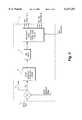
- FIG. 1is a schematic view of an exemplary motor controller assembly according to the present invention associated with a schematically illustrated brushless permanent magnet DC motor;
- FIG. 2is a schematic representation of a part of the internal workings of the microprocessor of FIG. 1 for below base speed operation;
- FIG. 3is a view like that of FIG. 2 only for substantially equal to or above base speed operation
- FIG. 4is diagrammatic representation illustrating the relationship between the variable PIOHP put out by a PI regulator according to the invention and two truth tables according to the invention.
- FIG. 1schematically illustrates the hardware utilized for the motor controller assembly according to the invention.
- Element 1is a power amplifier, which comprises or consists of four, six, or more power electronics switches 7, such as IGBTs or MOSFETs.
- the number of the electronic switches 7 useddepends upon the number of phases of the motor 2.
- Each phasehas two switches 7, a top switch 7a and a bottom switch 7b (see FIG. 1).
- the two switches 7 for each phaseare connected in series and the join point is also connected to the corresponding phase of the motor 2.
- the top switch 7ais connected to a positive bus and the bottom switch 7b is connected to the negative bus through a current sensor 6 as illustrated in FIG. 1.
- the gates of the switches 7are controlled by microprocessor 5.
- the number of bits of the microprocessor 5can be as small as eight.
- the brushless permanent magnet DC motor 2has conventional Hall sensors (one for each phase) 3 mounted on its end cap.
- the Hall sensors 3are commutation position sensors, which are triggered by a permanent magnet located on the rotor of motor 2.
- a conventional frequency to voltage converter (F/V converter) 4converts the Hall signals to voltage signals that represent the motor 2 speed.
- the current sensor 6is for motor 2 torque regulation. When the motor 2 operates below the base speed (i.e., a speed at which the back EMF of the motor matches the supply voltage), there are no significant differences between the controller of the invention and a conventional microprocessor controller.
- the microprocessor 5 softwareThere are two regulation loops in the microprocessor 5 software according to the invention: a speed loop and a torque loop.
- the torque loopis closed by the current sensor 6.
- the speed loopis closed by the F/V converter 4 which receives input signals Hall sensors 3.
- the microprocessor 5sends pulse width modulation (PWM) signals to the gates of switches 7 to control the motor 2 to a desired speed.
- PWMpulse width modulation
- FIG 2.An exemplary control mechanism for below base speed operation is illustrated in FIG 2.
- numerical switch S1 in the microprocessor softwareis closed.
- the output of the speed loop 10is the input command of the torque loop 1, and the output of the torque loop 11 is the PWM duty cycle.
- the power amplifier 1 of the inventionhas PWM on its bottom switches 7b.
- a commutation truth tablewhich is based on a conventional commutation truth table in the software of the microprocessor 5 is executed to logically control gating of the power amplifier.
- the commutation truth table for a three phase motor (2)is as follows:
- the control mechanismcomprises or consists of three components in the software of the microprocessor 5 as schematically illustrated in FIG. 3:
- the PI speed regulator 14, the time delay mechanism 15, and two above speed jump tableswhich are based on the below base speed commutation truth table.
- the first jump tableis obtained from the normal commutation truth table (above) by forward rotating one step, while the second jump table is obtained from the commutation truth table by forward rotating two steps.
- the jump tablesare:
- the key to regulating the motor speed during above base speed operationis to determine a proper time delay between the edge of the most recently triggered Hall sensor 3 and the time to switch to the next commutation step.
- This inventionpresents a method to do that automatically and without knowing the parameters of the motor 2 except the voltage sensitivity of the motor 2.
- the PI regulator 14is used.
- PIOHPis the output of the PI regulator in the microprocessor 5 software.
- Kp and K Iare proportional gain and integral gain respectively; T is sampling period; and e is "error", which is equal to difference between speed command and measured speed. Consequently, one sixth of the period of the Hall sensor 3 is calculated from the measured motor speed (from F/V converter 4), Thall.
- the time delay, TD, between the edge of the most recently triggered Hall sensor 3 and the time to switch to the next commutation stepis based on the following two equations:
- AAis equal to 2/3 of FF and FF is the maximum number which can be stored in a signed memory of a microprocessor.
- AA and FFare equal to $AA and $FF respectively for an 8 bit microprocessor.
- $AAis the hexadecimal representation of 170
- $FFis the hexadecimal representation of 255.
- FIG. 4schematically illustrates the relationship between variable PIOHP and the two jump tables.
- PIOHPWhen PIOHP is less than $AA, the first above base jump table is used.
- the time delay TDcontrols the motor 2 speed.
- PIOHPis equal or greater than $AA, control rotates to the second jump table.
- the new time delay (TD) valuewill still control the motor 2 speed.
- TD for the first tablegives a substantially synchronous torque angle for about 0 to 60 degrees
- TD for the second tablegives a substantially synchronous torque angle for about 60 to 85 degrees. Because 90 degrees is not a stable operating angle, one has to limit the maximum torque angle to less than about 85 degrees.
Landscapes
- Engineering & Computer Science (AREA)
- Power Engineering (AREA)
- Control Of Motors That Do Not Use Commutators (AREA)
Abstract
Description
______________________________________ Hall C Hall B Hall A Gating ______________________________________ 0 0 1 A top on and B bottom PWM 0 1 0 B top on and C bottom PWM 0 1 1 A top on and C bottom PWM 1 0 0 C top on and A bottom PWM 1 0 1 C top on and B bottom PWM 1 1 0 B top on and A bottom PWM ______________________________________
______________________________________ Commutation Truth Table Hall C Hall B Hall A Gating ______________________________________ 0 0 1 A top (switch 7a) on and B bottom (switch 7b) PWM 0 1 0 B top on and C bottom PWM 0 1 1 A top on and C bottom PWM 1 0 0 C top on and A bottom PWM 1 0 1 C top on and B bottom PWM 1 1 0 B top on and A bottom PWM ______________________________________
______________________________________ Hall C Hall B Hall A Gating ______________________________________ First Jump (Truth) Table 0 0 1 A top on and C bottom on 0 1 0 B top on and A bottom on 0 1 1 B top on and C bottom on 1 0 0 C top on and B bottom on 1 0 1 A top on and B bottom on 1 1 0 C top on and A bottom on Second Jump (Truth) Table 0 0 1 B top on and C bottom on 0 1 0 C top on and A bottom on 0 1 1 B top on and A bottom on 1 0 0 A top on and B bottom on 1 0 1 A top on and C bottom on 1 1 0 C top on and B bottom on ______________________________________
TD=1.5*Thall*(AA-PIOHP)/FF;
TD=1.5*Thall*[AA/2+FF-PIOHP]/FF;
Claims (23)
______________________________________ Hall C Hall B Hall A Gating ______________________________________ 0 0 1 A top on and B bottom PWM 0 1 0 B top on and C bottom PWM 0 1 1 A top on and C bottom PWM 1 0 0 C top on and A bottom PWM 1 0 1 C top on and B bottom PWM 1 1 0 B top on and A bottom PWM ______________________________________
______________________________________ Hall C Hall B Hall A Gating ______________________________________ 0 0 1 A top on and C bottom on 0 1 0 B top on and A bottom on 0 1 1 B top on and C bottom on 1 0 0 C top on and B bottom on 1 0 1 A top on and B bottom on 1 1 0 C top on and A bottom on ______________________________________
______________________________________ Hall C Hall B Hall A Gating ______________________________________ 0 0 1 B top on and C bottom on 0 1 0 C top on and A bottom on 0 1 1 B top on and A bottom on 1 0 0 A top on and B bottom on 1 0 1 A top on and C bottom on 1 1 0 C top on and B bottom on ______________________________________
______________________________________ Hall C Hall B Hall A Gating ______________________________________ 0 0 1 A top on and B bottom PWM 0 1 0 B top on and C bottom PWM 0 1 1 A top on and C bottom PWM 1 0 0 C top on and A bottom PWM 1 0 1 C top on and B bottom PWM 1 1 0 B top on and A bottom PWM ______________________________________
______________________________________ Hall C Hall B Hall A Gating ______________________________________ 0 0 1 A top on and B bottom PWM 0 1 0 B top on and C bottom PWM 0 1 1 A top on and C bottom PWM 1 0 0 C top on and A bottom PWM 1 0 1 C top on and B bottom PWM 1 1 0 B top on and A bottom PWM ______________________________________
Priority Applications (4)
| Application Number | Priority Date | Filing Date | Title |
|---|---|---|---|
| US09/185,080US6137251A (en) | 1998-07-31 | 1998-11-03 | Brushless DC motor controller with speed control from zero to above based speed |
| PCT/US1999/008750WO2000007289A1 (en) | 1998-07-31 | 1999-04-21 | Brushless dc motor controller with speed control from zero to above base speed |
| AU37545/99AAU3754599A (en) | 1998-07-31 | 1999-04-21 | Brushless dc motor controller with speed control from zero to above base speed |
| TW088110470ATW453019B (en) | 1998-07-31 | 1999-06-22 | Brushless DC motor controller with speed control from zero to above base speed |
Applications Claiming Priority (2)
| Application Number | Priority Date | Filing Date | Title |
|---|---|---|---|
| US9495198P | 1998-07-31 | 1998-07-31 | |
| US09/185,080US6137251A (en) | 1998-07-31 | 1998-11-03 | Brushless DC motor controller with speed control from zero to above based speed |
Publications (1)
| Publication Number | Publication Date |
|---|---|
| US6137251Atrue US6137251A (en) | 2000-10-24 |
Family
ID=26789377
Family Applications (1)
| Application Number | Title | Priority Date | Filing Date |
|---|---|---|---|
| US09/185,080Expired - Fee RelatedUS6137251A (en) | 1998-07-31 | 1998-11-03 | Brushless DC motor controller with speed control from zero to above based speed |
Country Status (4)
| Country | Link |
|---|---|
| US (1) | US6137251A (en) |
| AU (1) | AU3754599A (en) |
| TW (1) | TW453019B (en) |
| WO (1) | WO2000007289A1 (en) |
Cited By (24)
| Publication number | Priority date | Publication date | Assignee | Title |
|---|---|---|---|---|
| EP1271752A1 (en)* | 2001-06-13 | 2003-01-02 | HSU, Chun-Pu | Device for increasing the rotation speed of a permanent magnet motor |
| WO2003012974A1 (en)* | 2001-08-02 | 2003-02-13 | Ballard Power Systems Corporation | Method and apparatus for high performance permanent magnet motor speed control with limited position information |
| US6580235B2 (en)* | 2000-07-17 | 2003-06-17 | Johnson Controls Automotive Electronics | Electric motor with two modes of power supply switching |
| WO2003084047A1 (en)* | 2002-03-27 | 2003-10-09 | Mol Belting Company | Controller for a brushless dc motor |
| US20040012204A1 (en)* | 2002-06-06 | 2004-01-22 | Walter Richard T. | Starter system for portable internal combustion engine electric generators using a portable universal battery pack |
| FR2864721A1 (en)* | 2003-12-25 | 2005-07-01 | Mitsubishi Electric Corp | METHOD FOR CONTROLLING AN ENGINE WITHOUT MANIFOLD AND DEVICE FOR CONTROLLING STEERING OF AN ENGINE WITHOUT MANIFOLD |
| US20060170218A1 (en)* | 2002-06-06 | 2006-08-03 | Grant Jeffrey P | Starter system for portable internal combustion engine electric generators using a portable universal battery pack |
| FR2886074A1 (en)* | 2005-05-18 | 2006-11-24 | Mitsubishi Electric Corp | DRIVE METHOD FOR A BRUSHLESS MOTOR AND DRIVING CONTROL DEVICE |
| US20070120509A1 (en)* | 2005-11-30 | 2007-05-31 | Beifus Brian L | Methods and systems for providing pwm control signals to an electronically commutated motor |
| US20070120366A1 (en)* | 2002-06-06 | 2007-05-31 | Grant Jeffrey P | Starter system for portable internal combustion engine electric generators using a portable universal battery pack |
| US20080191660A1 (en)* | 2007-01-26 | 2008-08-14 | Siemens Aktiengesellschaft | Method and device for controlling a three-phase machine having several phase windings, which can be controlled by means of pulse width modulation |
| US20090136361A1 (en)* | 2005-09-01 | 2009-05-28 | Alois Greven | Vacuum turbomolecular pump |
| US20090295169A1 (en)* | 2002-06-06 | 2009-12-03 | Black& Decker Inc. | Starter system for portable internal combustion engine electric generators using a portable universal battery pack |
| US7782626B2 (en) | 2007-02-02 | 2010-08-24 | Black & Decker Inc. | Portable power driven system with battery anti-theft apparatus |
| US7989969B2 (en) | 2002-06-06 | 2011-08-02 | Black & Decker Inc. | Universal power tool battery pack coupled to a portable internal combustion engine |
| WO2011128107A1 (en) | 2010-04-17 | 2011-10-20 | Audi Ag | Method for controlling position and/or speed |
| WO2011120816A3 (en)* | 2010-03-31 | 2012-07-26 | Robert Bosch Gmbh | Method for driving an electric motor |
| CN103066916A (en)* | 2012-12-13 | 2013-04-24 | 中国人民解放军军事交通学院 | Separately excited motor controller applied to battery driven vehicle |
| CN104727725A (en)* | 2013-12-23 | 2015-06-24 | 加布里耶尔·赖奇有限责任两合公司 | Drive and control system for lifting gates |
| CN106026797A (en)* | 2016-07-14 | 2016-10-12 | 重庆编福科技有限公司 | Method of accurate positioning and displacement calculation on actuator driven by brushless DC motor |
| US20180351487A1 (en)* | 2015-11-23 | 2018-12-06 | Safran Electrical & Power | Method for controlling a synchronous machine with permanent magnets and corresponding device |
| US10829989B2 (en) | 2016-06-28 | 2020-11-10 | Gabrijel Rejc | Motor-operable and vertically movable gate |
| US10914117B2 (en) | 2016-06-28 | 2021-02-09 | Gabrijel Rejc | Vertically movable gate with a gate panel |
| US11499369B2 (en) | 2016-12-15 | 2022-11-15 | Gabrijel Rejc Gmbh & Co. Kg | Gate with a crash-down prevention mechanism and method for triggering the crash-down prevention mechanism |
Families Citing this family (5)
| Publication number | Priority date | Publication date | Assignee | Title |
|---|---|---|---|---|
| US6982281B1 (en) | 2000-11-17 | 2006-01-03 | Lipocine Inc | Pharmaceutical compositions and dosage forms for administration of hydrophobic drugs |
| JP2004508793A (en)* | 2000-09-07 | 2004-03-18 | デルファイ・テクノロジーズ・インコーポレーテッド | Machine torque control method and device |
| CN105099287B (en)* | 2015-07-06 | 2017-06-13 | 湖南工业大学 | The remote arrangements for speed regulation of DC brushless motor |
| TWI626455B (en)* | 2016-04-19 | 2018-06-11 | 義守大學 | Frequency-to-voltage converter |
| CN114865956B (en)* | 2022-05-17 | 2025-01-14 | 陕西安信医学技术开发有限公司 | A reversing speed control device |
Citations (22)
| Publication number | Priority date | Publication date | Assignee | Title |
|---|---|---|---|---|
| US4415844A (en)* | 1981-02-09 | 1983-11-15 | Priam | Digital motor speed controller |
| US4447771A (en)* | 1981-08-31 | 1984-05-08 | Kollmorgen Technologies Corporation | Control system for synchronous brushless motors |
| US4490661A (en)* | 1983-07-28 | 1984-12-25 | Kollmorgen Technologies Corporation | Control system for synchronous brushless motors utilizing torque angle control |
| US4528486A (en)* | 1983-12-29 | 1985-07-09 | The Boeing Company | Controller for a brushless DC motor |
| US4546293A (en)* | 1982-08-24 | 1985-10-08 | Sundstrand Corporation | Motor control for a brushless DC motor |
| US4608527A (en)* | 1982-12-20 | 1986-08-26 | Sundstrand Corporation | Phase advance waveform generator for brushless DC actuator system controller |
| US4661750A (en)* | 1984-08-22 | 1987-04-28 | Brother Kogyo Kabushiki Kaisha | Device for controlling DC motor |
| US4835448A (en)* | 1987-12-28 | 1989-05-30 | Sundstrand Corporation | Brushless DC motor torque control |
| US4962376A (en)* | 1987-03-31 | 1990-10-09 | Canon Kabushiki Kaisha | Display control apparatus having a plurality of driving voltage supplying means |
| US5032771A (en)* | 1990-08-09 | 1991-07-16 | Allen-Bradley Company, Inc. | Slip control based on sensing voltage fed to an induction motor |
| US5077506A (en)* | 1989-02-03 | 1991-12-31 | Dyonics, Inc. | Microprocessor controlled arthroscopic surgical system |
| US5200675A (en)* | 1990-11-06 | 1993-04-06 | Zen Zen Electric Company Ltd. | Commutation circuit for a brushless d.c. motor |
| US5229693A (en)* | 1991-02-28 | 1993-07-20 | Kabushiki Kaisha Toshiba | Driving control apparatus for brushless motor with optimum controlled converter |
| US5317243A (en)* | 1991-10-03 | 1994-05-31 | Sgs-Thomson Microelectronics, Inc. | Method and apparatus for detecting velocity profiles of a spinning rotor of a polyphase DC motor |
| US5319291A (en)* | 1993-02-17 | 1994-06-07 | Pitney Bowes Inc. | Brushless motor utilizing FET drivers |
| US5386569A (en)* | 1992-01-23 | 1995-01-31 | Mitsubishi Denki Kabushiki Kaisha | Programmable controller having directly executable CPU instructions |
| US5410234A (en)* | 1992-01-28 | 1995-04-25 | Okuma Corporation | Motor drive control apparatus |
| US5469039A (en)* | 1991-09-25 | 1995-11-21 | Switched Reluctance Drives Limited | Control of switched reluctance machines |
| EP0716499A1 (en)* | 1994-12-07 | 1996-06-12 | General Motors Corporation | Controller for a brushless DC Motor |
| US5677605A (en)* | 1989-08-22 | 1997-10-14 | Unique Mobility, Inc. | Brushless DC motor using phase timing advancement |
| WO1997050171A1 (en)* | 1996-06-26 | 1997-12-31 | British Nuclear Fuels Plc | Control systems for electric motor-generators |
| US5859510A (en)* | 1993-02-17 | 1999-01-12 | Pitney Bowes Inc. | Commutation board for brushless motor |
- 1998
- 1998-11-03USUS09/185,080patent/US6137251A/ennot_activeExpired - Fee Related
- 1999
- 1999-04-21WOPCT/US1999/008750patent/WO2000007289A1/enactiveApplication Filing
- 1999-04-21AUAU37545/99Apatent/AU3754599A/ennot_activeAbandoned
- 1999-06-22TWTW088110470Apatent/TW453019B/enactive
Patent Citations (22)
| Publication number | Priority date | Publication date | Assignee | Title |
|---|---|---|---|---|
| US4415844A (en)* | 1981-02-09 | 1983-11-15 | Priam | Digital motor speed controller |
| US4447771A (en)* | 1981-08-31 | 1984-05-08 | Kollmorgen Technologies Corporation | Control system for synchronous brushless motors |
| US4546293A (en)* | 1982-08-24 | 1985-10-08 | Sundstrand Corporation | Motor control for a brushless DC motor |
| US4608527A (en)* | 1982-12-20 | 1986-08-26 | Sundstrand Corporation | Phase advance waveform generator for brushless DC actuator system controller |
| US4490661A (en)* | 1983-07-28 | 1984-12-25 | Kollmorgen Technologies Corporation | Control system for synchronous brushless motors utilizing torque angle control |
| US4528486A (en)* | 1983-12-29 | 1985-07-09 | The Boeing Company | Controller for a brushless DC motor |
| US4661750A (en)* | 1984-08-22 | 1987-04-28 | Brother Kogyo Kabushiki Kaisha | Device for controlling DC motor |
| US4962376A (en)* | 1987-03-31 | 1990-10-09 | Canon Kabushiki Kaisha | Display control apparatus having a plurality of driving voltage supplying means |
| US4835448A (en)* | 1987-12-28 | 1989-05-30 | Sundstrand Corporation | Brushless DC motor torque control |
| US5077506A (en)* | 1989-02-03 | 1991-12-31 | Dyonics, Inc. | Microprocessor controlled arthroscopic surgical system |
| US5677605A (en)* | 1989-08-22 | 1997-10-14 | Unique Mobility, Inc. | Brushless DC motor using phase timing advancement |
| US5032771A (en)* | 1990-08-09 | 1991-07-16 | Allen-Bradley Company, Inc. | Slip control based on sensing voltage fed to an induction motor |
| US5200675A (en)* | 1990-11-06 | 1993-04-06 | Zen Zen Electric Company Ltd. | Commutation circuit for a brushless d.c. motor |
| US5229693A (en)* | 1991-02-28 | 1993-07-20 | Kabushiki Kaisha Toshiba | Driving control apparatus for brushless motor with optimum controlled converter |
| US5469039A (en)* | 1991-09-25 | 1995-11-21 | Switched Reluctance Drives Limited | Control of switched reluctance machines |
| US5317243A (en)* | 1991-10-03 | 1994-05-31 | Sgs-Thomson Microelectronics, Inc. | Method and apparatus for detecting velocity profiles of a spinning rotor of a polyphase DC motor |
| US5386569A (en)* | 1992-01-23 | 1995-01-31 | Mitsubishi Denki Kabushiki Kaisha | Programmable controller having directly executable CPU instructions |
| US5410234A (en)* | 1992-01-28 | 1995-04-25 | Okuma Corporation | Motor drive control apparatus |
| US5319291A (en)* | 1993-02-17 | 1994-06-07 | Pitney Bowes Inc. | Brushless motor utilizing FET drivers |
| US5859510A (en)* | 1993-02-17 | 1999-01-12 | Pitney Bowes Inc. | Commutation board for brushless motor |
| EP0716499A1 (en)* | 1994-12-07 | 1996-06-12 | General Motors Corporation | Controller for a brushless DC Motor |
| WO1997050171A1 (en)* | 1996-06-26 | 1997-12-31 | British Nuclear Fuels Plc | Control systems for electric motor-generators |
Cited By (42)
| Publication number | Priority date | Publication date | Assignee | Title |
|---|---|---|---|---|
| US6580235B2 (en)* | 2000-07-17 | 2003-06-17 | Johnson Controls Automotive Electronics | Electric motor with two modes of power supply switching |
| EP1271752A1 (en)* | 2001-06-13 | 2003-01-02 | HSU, Chun-Pu | Device for increasing the rotation speed of a permanent magnet motor |
| US6700342B2 (en) | 2001-08-02 | 2004-03-02 | Ballard Power Systems Corporation | Method and apparatus for high performance permanent magnet motor speed control with limited position information |
| WO2003012974A1 (en)* | 2001-08-02 | 2003-02-13 | Ballard Power Systems Corporation | Method and apparatus for high performance permanent magnet motor speed control with limited position information |
| WO2003084047A1 (en)* | 2002-03-27 | 2003-10-09 | Mol Belting Company | Controller for a brushless dc motor |
| US7309928B2 (en) | 2002-06-06 | 2007-12-18 | Black & Decker Inc. | Starter system for portable internal combustion engine electric generators using a portable universal battery pack |
| US7989969B2 (en) | 2002-06-06 | 2011-08-02 | Black & Decker Inc. | Universal power tool battery pack coupled to a portable internal combustion engine |
| US20060170218A1 (en)* | 2002-06-06 | 2006-08-03 | Grant Jeffrey P | Starter system for portable internal combustion engine electric generators using a portable universal battery pack |
| US8319357B2 (en) | 2002-06-06 | 2012-11-27 | Black & Decker Inc. | Starter system for portable internal combustion engine electric generators using a portable universal battery pack |
| US7180200B2 (en)* | 2002-06-06 | 2007-02-20 | Black & Decker Inc. | Starter system for portable internal combustion engine electric generators using a portable universal battery pack |
| US20040012204A1 (en)* | 2002-06-06 | 2004-01-22 | Walter Richard T. | Starter system for portable internal combustion engine electric generators using a portable universal battery pack |
| US20070120366A1 (en)* | 2002-06-06 | 2007-05-31 | Grant Jeffrey P | Starter system for portable internal combustion engine electric generators using a portable universal battery pack |
| US7687926B2 (en) | 2002-06-06 | 2010-03-30 | Black & Decker Inc. | Starter system for portable internal combustion engine electric generators using a portable universal battery pack |
| US9276438B2 (en) | 2002-06-06 | 2016-03-01 | Black & Decker Inc. | Universal power tool battery pack coupled to a portable internal combustion engine |
| US8759991B2 (en) | 2002-06-06 | 2014-06-24 | Black & Decker Inc. | Universal power tool battery pack coupled to a portable internal combustion engine |
| US20090295169A1 (en)* | 2002-06-06 | 2009-12-03 | Black& Decker Inc. | Starter system for portable internal combustion engine electric generators using a portable universal battery pack |
| FR2864721A1 (en)* | 2003-12-25 | 2005-07-01 | Mitsubishi Electric Corp | METHOD FOR CONTROLLING AN ENGINE WITHOUT MANIFOLD AND DEVICE FOR CONTROLLING STEERING OF AN ENGINE WITHOUT MANIFOLD |
| FR2886074A1 (en)* | 2005-05-18 | 2006-11-24 | Mitsubishi Electric Corp | DRIVE METHOD FOR A BRUSHLESS MOTOR AND DRIVING CONTROL DEVICE |
| US20090136361A1 (en)* | 2005-09-01 | 2009-05-28 | Alois Greven | Vacuum turbomolecular pump |
| US20070120509A1 (en)* | 2005-11-30 | 2007-05-31 | Beifus Brian L | Methods and systems for providing pwm control signals to an electronically commutated motor |
| US7482770B2 (en)* | 2005-11-30 | 2009-01-27 | Regal-Beloit Corporation | Methods and systems for providing PWM control signals to an electronically commutated motor |
| US20080191660A1 (en)* | 2007-01-26 | 2008-08-14 | Siemens Aktiengesellschaft | Method and device for controlling a three-phase machine having several phase windings, which can be controlled by means of pulse width modulation |
| US7906929B2 (en)* | 2007-01-26 | 2011-03-15 | Siemens Aktiengesellschaft | Method and device for controlling a three-phase machine having several phase windings, which can be controlled by means of pulse width modulation |
| US7782626B2 (en) | 2007-02-02 | 2010-08-24 | Black & Decker Inc. | Portable power driven system with battery anti-theft apparatus |
| WO2011120816A3 (en)* | 2010-03-31 | 2012-07-26 | Robert Bosch Gmbh | Method for driving an electric motor |
| CN102812630A (en)* | 2010-03-31 | 2012-12-05 | 罗伯特·博世有限公司 | Method for driving an electric motor |
| US9030138B2 (en) | 2010-03-31 | 2015-05-12 | Robert Bosch Gmbh | Method for driving an electric motor |
| CN102812630B (en)* | 2010-03-31 | 2016-06-15 | 罗伯特·博世有限公司 | Method for excited electric motor |
| WO2011128107A1 (en) | 2010-04-17 | 2011-10-20 | Audi Ag | Method for controlling position and/or speed |
| DE102010015316A1 (en) | 2010-04-17 | 2011-10-20 | Audi Ag | Method for controlling position and / or speed |
| US8639417B2 (en) | 2010-04-17 | 2014-01-28 | Audi Ag | Method for regulating position and/or speed |
| CN103066916A (en)* | 2012-12-13 | 2013-04-24 | 中国人民解放军军事交通学院 | Separately excited motor controller applied to battery driven vehicle |
| CN104727725A (en)* | 2013-12-23 | 2015-06-24 | 加布里耶尔·赖奇有限责任两合公司 | Drive and control system for lifting gates |
| US20150176321A1 (en)* | 2013-12-23 | 2015-06-25 | Gabrijel Rejc Gmbh & Co. Kg | Drive and control system for lifting gates |
| US9416579B2 (en)* | 2013-12-23 | 2016-08-16 | Gabrijel Rejc Gmbh & Co. Kg | Drive and control system for lifting gates |
| CN104727725B (en)* | 2013-12-23 | 2018-07-17 | 加布里耶尔·赖奇有限责任两合公司 | Driving for overhead door and control system |
| US20180351487A1 (en)* | 2015-11-23 | 2018-12-06 | Safran Electrical & Power | Method for controlling a synchronous machine with permanent magnets and corresponding device |
| US10574159B2 (en)* | 2015-11-23 | 2020-02-25 | Safran Electrical & Power | Method for controlling a synchronous machine with permanent magnets and corresponding device |
| US10829989B2 (en) | 2016-06-28 | 2020-11-10 | Gabrijel Rejc | Motor-operable and vertically movable gate |
| US10914117B2 (en) | 2016-06-28 | 2021-02-09 | Gabrijel Rejc | Vertically movable gate with a gate panel |
| CN106026797A (en)* | 2016-07-14 | 2016-10-12 | 重庆编福科技有限公司 | Method of accurate positioning and displacement calculation on actuator driven by brushless DC motor |
| US11499369B2 (en) | 2016-12-15 | 2022-11-15 | Gabrijel Rejc Gmbh & Co. Kg | Gate with a crash-down prevention mechanism and method for triggering the crash-down prevention mechanism |
Also Published As
| Publication number | Publication date |
|---|---|
| TW453019B (en) | 2001-09-01 |
| AU3754599A (en) | 2000-02-21 |
| WO2000007289A1 (en) | 2000-02-10 |
Similar Documents
| Publication | Publication Date | Title |
|---|---|---|
| US6137251A (en) | Brushless DC motor controller with speed control from zero to above based speed | |
| US4713594A (en) | Start-up control for switched reluctance motor | |
| US6002226A (en) | Brushless DC motor control method and apparatus for reduced commutation noise | |
| US5739664A (en) | Induction motor drive controller | |
| US4961038A (en) | Torque estimator for switched reluctance machines | |
| US4933620A (en) | Control system for low speed switched reluctance motor | |
| US4707650A (en) | Control system for switched reluctance motor | |
| US5285135A (en) | Automatic adjustment of commutation delay for brushless DC motor for improved efficiency | |
| MacMinn et al. | Control of a switched-reluctance aircraft engine starter-generator over a very wide speed range | |
| US6307336B1 (en) | Closed loop control of PWM duty cycle | |
| US5440218A (en) | Reversible switched reluctance motor operating without a shaft position sensor | |
| US4933621A (en) | Current chopping strategy for switched reluctance machines | |
| US6646407B2 (en) | Electric motor control having DC-DC converter and method of using same | |
| EP0201872A2 (en) | Flux-weakening regime operation of an interior permanent magnet sychronous motor | |
| US5532561A (en) | Virtual hall-effect signal generating for a brushless sensorless electrical rotary machine | |
| GB2305033A (en) | Controlling brushless dc motors | |
| US5457374A (en) | Motor controller for operating an inverter in current-controlled and voltage-controlled modes | |
| US6150788A (en) | Load torque detection and drive current optimization determination met | |
| US6359413B1 (en) | Current control system for a switched reluctance motor | |
| US5281903A (en) | Method for drivingly controlling a variable reluctance type motor | |
| US6408130B1 (en) | Electric drive system with an electronically commuted DC motor in order to reduce torque irregularities | |
| US20030234626A1 (en) | Method and regulator based on peak current control for electric machines | |
| JP2756588B2 (en) | Brushless motor circuit for automatic door | |
| Yang et al. | Sliding mode control for switched reluctance motors: An experimental investigation | |
| JP2750453B2 (en) | Brushless motor circuit for automatic door |
Legal Events
| Date | Code | Title | Description |
|---|---|---|---|
| AS | Assignment | Owner name:S/L MONTEVIDEO TECHNOLOGY, INC., MINNESOTA Free format text:ASSIGNMENT OF ASSIGNORS INTEREST;ASSIGNORS:HUANG, HAO;NOLAN, DENNIS C.;REEL/FRAME:009578/0198 Effective date:19981029 | |
| AS | Assignment | Owner name:MELLON BANK, N.A., PENNSYLVANIA Free format text:SECURITY AGREEMENT;ASSIGNORS:SL INDUSTRIES, INC.;CEDAR CORPORATION;CONDOR D.C. POWER SUPPLIES, INC.;AND OTHERS;REEL/FRAME:012312/0902 Effective date:20011213 | |
| AS | Assignment | Owner name:SL MONTEVIDEO TECHNOLOGY, INC., NEW JERSEY Free format text:TERMINATION OF SECURITY INTEREST;ASSIGNOR:MELLON BANK, N.A.;REEL/FRAME:012698/0429 Effective date:20020226 | |
| AS | Assignment | Owner name:GE CAPITAL CFE, INC., ILLINOIS Free format text:SECURITY AGREEMENT;ASSIGNOR:SL MONTEVIDEO TECHNOLOGY, INC.;REEL/FRAME:012754/0554 Effective date:20020226 | |
| AS | Assignment | Owner name:SL DELAWARE, INC., DELAWARE Free format text:TERMINATION OF SECURITY INTEREST;ASSIGNOR:GE CAPITAL CFE, INC.;REEL/FRAME:013634/0721 Effective date:20021220 Owner name:SL INDUSTRIES, INC., NEW JERSEY Free format text:TERMINATION OF SECURITY INTEREST;ASSIGNOR:GE CAPITAL CFE, INC.;REEL/FRAME:013634/0721 Effective date:20021220 | |
| AS | Assignment | Owner name:LASALLE BUSINESS CREDIT, LLC, PENNSYLVANIA Free format text:SECURITY AGREEMENT;ASSIGNORS:SL INDUSTRIES, INC.;SL DELAWARE, INC.;SL DELAWARE HOLDINGS, INC.;AND OTHERS;REEL/FRAME:013634/0746 Effective date:20030106 | |
| FPAY | Fee payment | Year of fee payment:4 | |
| AS | Assignment | Owner name:BANK OF AMERICA, N.A., AS AGENT, PENNSYLVANIA Free format text:ASSIGNMENT OF ASSIGNORS INTEREST;ASSIGNORS:CONDOR DC POWER SUPPLIES, INC.;TEAL ELECTRONICS CORPORATION;RFL ELECTRONICS CORPORATION;AND OTHERS;REEL/FRAME:016945/0281 Effective date:20050803 | |
| AS | Assignment | Owner name:SLW HOLDINGS, INC., NEW JERSEY Free format text:ASSIGNMENT OF ASSIGNORS INTEREST;ASSIGNOR:LASALLE BUSINESS CREDIT, LLC;REEL/FRAME:016987/0824 Effective date:20050803 Owner name:CEDAR CORPORATION, NEW JERSEY Free format text:ASSIGNMENT OF ASSIGNORS INTEREST;ASSIGNOR:LASALLE BUSINESS CREDIT, LLC;REEL/FRAME:016987/0824 Effective date:20050803 Owner name:SL SURFACE TECHNOLOGIES, INC., NEW JERSEY Free format text:ASSIGNMENT OF ASSIGNORS INTEREST;ASSIGNOR:LASALLE BUSINESS CREDIT, LLC;REEL/FRAME:016987/0824 Effective date:20050803 Owner name:SL AUBURN, INC., NEW JERSEY Free format text:ASSIGNMENT OF ASSIGNORS INTEREST;ASSIGNOR:LASALLE BUSINESS CREDIT, LLC;REEL/FRAME:016987/0824 Effective date:20050803 Owner name:CONDOR HOLDINGS, INC., NEW JERSEY Free format text:ASSIGNMENT OF ASSIGNORS INTEREST;ASSIGNOR:LASALLE BUSINESS CREDIT, LLC;REEL/FRAME:016987/0824 Effective date:20050803 Owner name:SL DELAWARE, INC., NEW JERSEY Free format text:ASSIGNMENT OF ASSIGNORS INTEREST;ASSIGNOR:LASALLE BUSINESS CREDIT, LLC;REEL/FRAME:016987/0824 Effective date:20050803 Owner name:SL DELAWARE HOLDINGS, INC., NEW JERSEY Free format text:ASSIGNMENT OF ASSIGNORS INTEREST;ASSIGNOR:LASALLE BUSINESS CREDIT, LLC;REEL/FRAME:016987/0824 Effective date:20050803 Owner name:TEAL ELECTRONICS CORPORATION, NEW JERSEY Free format text:ASSIGNMENT OF ASSIGNORS INTEREST;ASSIGNOR:LASALLE BUSINESS CREDIT, LLC;REEL/FRAME:016987/0824 Effective date:20050803 Owner name:RFL ELECTRONICS, INC., NEW JERSEY Free format text:ASSIGNMENT OF ASSIGNORS INTEREST;ASSIGNOR:LASALLE BUSINESS CREDIT, LLC;REEL/FRAME:016987/0824 Effective date:20050803 Owner name:SL MONTEVIDEO TECHNOLOGY, INC., NEW JERSEY Free format text:ASSIGNMENT OF ASSIGNORS INTEREST;ASSIGNOR:LASALLE BUSINESS CREDIT, LLC;REEL/FRAME:016987/0824 Effective date:20050803 Owner name:CONDOR D.C. POWER SUPPLIES, INC., NEW JERSEY Free format text:ASSIGNMENT OF ASSIGNORS INTEREST;ASSIGNOR:LASALLE BUSINESS CREDIT, LLC;REEL/FRAME:016987/0824 Effective date:20050803 Owner name:SL INDUSTRIES, INC., NEW JERSEY Free format text:ASSIGNMENT OF ASSIGNORS INTEREST;ASSIGNOR:LASALLE BUSINESS CREDIT, LLC;REEL/FRAME:016987/0824 Effective date:20050803 Owner name:WABER POWER, LTD., NEW JERSEY Free format text:ASSIGNMENT OF ASSIGNORS INTEREST;ASSIGNOR:LASALLE BUSINESS CREDIT, LLC;REEL/FRAME:016987/0824 Effective date:20050803 | |
| REMI | Maintenance fee reminder mailed | ||
| AS | Assignment | Owner name:BANK OF AMERICA, N.A., PENNSYLVANIA Free format text:SECURITY AGREEMENT;ASSIGNORS:SL INDUSTRIES, INC.;SL DELAWARE, INC.;SL DELAWARE HOLDINGS, INC.;AND OTHERS;REEL/FRAME:021731/0146 Effective date:20081023 | |
| LAPS | Lapse for failure to pay maintenance fees | ||
| STCH | Information on status: patent discontinuation | Free format text:PATENT EXPIRED DUE TO NONPAYMENT OF MAINTENANCE FEES UNDER 37 CFR 1.362 | |
| FP | Lapsed due to failure to pay maintenance fee | Effective date:20081024 | |
| AS | Assignment | Owner name:SL INDUSTRIES, INC., NEW JERSEY Free format text:RELEASE BY SECURED PARTY;ASSIGNOR:BANK OF AMERICA, N.A.;REEL/FRAME:028795/0546 Effective date:20120809 Owner name:SL DELAWARE, INC., NEW JERSEY Free format text:RELEASE BY SECURED PARTY;ASSIGNOR:BANK OF AMERICA, N.A.;REEL/FRAME:028795/0546 Effective date:20120809 Owner name:SL DELAWARE HOLDINGS, INC., NEW JERSEY Free format text:RELEASE BY SECURED PARTY;ASSIGNOR:BANK OF AMERICA, N.A.;REEL/FRAME:028795/0546 Effective date:20120809 Owner name:MTE CORPORATION, NEW JERSEY Free format text:RELEASE BY SECURED PARTY;ASSIGNOR:BANK OF AMERICA, N.A.;REEL/FRAME:028795/0546 Effective date:20120809 Owner name:RFL ELECTRONICS INC., NEW JERSEY Free format text:RELEASE BY SECURED PARTY;ASSIGNOR:BANK OF AMERICA, N.A.;REEL/FRAME:028795/0546 Effective date:20120809 Owner name:SL MONTEVIDEO TECHNOLOGY, INC., NEW JERSEY Free format text:RELEASE BY SECURED PARTY;ASSIGNOR:BANK OF AMERICA, N.A.;REEL/FRAME:028795/0546 Effective date:20120809 Owner name:CEDAR CORPORATION, NEW JERSEY Free format text:RELEASE BY SECURED PARTY;ASSIGNOR:BANK OF AMERICA, N.A.;REEL/FRAME:028795/0546 Effective date:20120809 Owner name:TEAL ELECTRONICS CORPORATION, NEW JERSEY Free format text:RELEASE BY SECURED PARTY;ASSIGNOR:BANK OF AMERICA, N.A.;REEL/FRAME:028795/0546 Effective date:20120809 Owner name:MEX HOLDINGS LLC, NEW JERSEY Free format text:RELEASE BY SECURED PARTY;ASSIGNOR:BANK OF AMERICA, N.A.;REEL/FRAME:028795/0546 Effective date:20120809 Owner name:SL POWER ELECTRONIC CORPORATION, NEW JERSEY Free format text:RELEASE BY SECURED PARTY;ASSIGNOR:BANK OF AMERICA, N.A.;REEL/FRAME:028795/0546 Effective date:20120809 Owner name:SLGC HOLDINGS, INC., NEW JERSEY Free format text:RELEASE BY SECURED PARTY;ASSIGNOR:BANK OF AMERICA, N.A.;REEL/FRAME:028795/0546 Effective date:20120809 Owner name:SLW HOLDINGS, INC., NEW JERSEY Free format text:RELEASE BY SECURED PARTY;ASSIGNOR:BANK OF AMERICA, N.A.;REEL/FRAME:028795/0546 Effective date:20120809 Owner name:SL AUBURN, INC., NEW JERSEY Free format text:RELEASE BY SECURED PARTY;ASSIGNOR:BANK OF AMERICA, N.A.;REEL/FRAME:028795/0546 Effective date:20120809 Owner name:SL SURFACE TECHNOLOGIES, INC., NEW JERSEY Free format text:RELEASE BY SECURED PARTY;ASSIGNOR:BANK OF AMERICA, N.A.;REEL/FRAME:028795/0546 Effective date:20120809 Owner name:CONDOR D.C. POWER SUPPLIES, INC., NEW JERSEY Free format text:RELEASE BY SECURED PARTY;ASSIGNOR:BANK OF AMERICA, N.A.;REEL/FRAME:028795/0619 Effective date:20120809 Owner name:PNC BANK, NATIONAL ASSOCIATION, PENNSYLVANIA Free format text:SECURITY AGREEMENT;ASSIGNORS:SL INDUSTRIES, INC.;MTE CORPORATION;SL DELAWARE HOLDINGS, INC.;AND OTHERS;REEL/FRAME:028802/0081 Effective date:20120809 |