US6135998A - Method and apparatus for pulsed plasma-mediated electrosurgery in liquid media - Google Patents
Method and apparatus for pulsed plasma-mediated electrosurgery in liquid mediaDownload PDFInfo
- Publication number
- US6135998A US6135998AUS09/270,401US27040199AUS6135998AUS 6135998 AUS6135998 AUS 6135998AUS 27040199 AUS27040199 AUS 27040199AUS 6135998 AUS6135998 AUS 6135998A
- Authority
- US
- United States
- Prior art keywords
- less
- nanoseconds
- pulse
- electrode
- watts
- Prior art date
- Legal status (The legal status is an assumption and is not a legal conclusion. Google has not performed a legal analysis and makes no representation as to the accuracy of the status listed.)
- Expired - Lifetime
Links
- 238000000034methodMethods0.000titleclaimsabstractdescription84
- 239000007788liquidSubstances0.000titleclaimsdescription25
- 230000001404mediated effectEffects0.000title1
- 239000000523sampleSubstances0.000claimsabstractdescription44
- 238000005520cutting processMethods0.000claimsabstractdescription41
- 230000002207retinal effectEffects0.000claimsabstractdescription6
- 239000002775capsuleSubstances0.000claimsdescription9
- 210000000554irisAnatomy0.000claimsdescription6
- 230000035939shockEffects0.000abstractdescription14
- 230000006378damageEffects0.000abstractdescription13
- 238000001356surgical procedureMethods0.000abstractdescription9
- 210000001519tissueAnatomy0.000description72
- 230000015572biosynthetic processEffects0.000description13
- 239000003990capacitorSubstances0.000description6
- 230000008859changeEffects0.000description6
- 238000012512characterization methodMethods0.000description6
- 238000002224dissectionMethods0.000description6
- 230000008901benefitEffects0.000description4
- 230000009471actionEffects0.000description3
- 239000003989dielectric materialSubstances0.000description3
- 230000000694effectsEffects0.000description3
- 238000002406microsurgeryMethods0.000description3
- 210000004872soft tissueAnatomy0.000description3
- 239000007787solidSubstances0.000description3
- 208000001351Epiretinal MembraneDiseases0.000description2
- 238000002679ablationMethods0.000description2
- 238000005345coagulationMethods0.000description2
- 230000015271coagulationEffects0.000description2
- 239000012530fluidSubstances0.000description2
- 239000007789gasSubstances0.000description2
- 230000007704transitionEffects0.000description2
- XLYOFNOQVPJJNP-UHFFFAOYSA-NwaterSubstancesOXLYOFNOQVPJJNP-UHFFFAOYSA-N0.000description2
- 208000002177CataractDiseases0.000description1
- UFHFLCQGNIYNRP-UHFFFAOYSA-NHydrogenChemical compound[H][H]UFHFLCQGNIYNRP-UHFFFAOYSA-N0.000description1
- 208000000913Kidney CalculiDiseases0.000description1
- 206010029148NephrolithiasisDiseases0.000description1
- VYPSYNLAJGMNEJ-UHFFFAOYSA-NSilicium dioxideChemical compoundO=[Si]=OVYPSYNLAJGMNEJ-UHFFFAOYSA-N0.000description1
- 210000001742aqueous humorAnatomy0.000description1
- QVGXLLKOCUKJST-UHFFFAOYSA-Natomic oxygenChemical compound[O]QVGXLLKOCUKJST-UHFFFAOYSA-N0.000description1
- 230000002238attenuated effectEffects0.000description1
- 230000005540biological transmissionEffects0.000description1
- 210000004204blood vesselAnatomy0.000description1
- 210000000845cartilageAnatomy0.000description1
- 230000005684electric fieldEffects0.000description1
- 239000007772electrode materialSubstances0.000description1
- 238000005530etchingMethods0.000description1
- 239000000835fiberSubstances0.000description1
- 239000005350fused silica glassSubstances0.000description1
- 238000002682general surgeryMethods0.000description1
- 239000011521glassSubstances0.000description1
- 230000020169heat generationEffects0.000description1
- 238000010438heat treatmentMethods0.000description1
- 239000001257hydrogenSubstances0.000description1
- 229910052739hydrogenInorganic materials0.000description1
- 239000011810insulating materialSubstances0.000description1
- 230000004807localizationEffects0.000description1
- 239000000463materialSubstances0.000description1
- 230000004048modificationEffects0.000description1
- 238000012986modificationMethods0.000description1
- 239000001301oxygenSubstances0.000description1
- 229910052760oxygenInorganic materials0.000description1
Images


Classifications
- A—HUMAN NECESSITIES
- A61—MEDICAL OR VETERINARY SCIENCE; HYGIENE
- A61B—DIAGNOSIS; SURGERY; IDENTIFICATION
- A61B18/00—Surgical instruments, devices or methods for transferring non-mechanical forms of energy to or from the body
- A61B18/04—Surgical instruments, devices or methods for transferring non-mechanical forms of energy to or from the body by heating
- A61B18/12—Surgical instruments, devices or methods for transferring non-mechanical forms of energy to or from the body by heating by passing a current through the tissue to be heated, e.g. high-frequency current
- A61B18/1206—Generators therefor
- A—HUMAN NECESSITIES
- A61—MEDICAL OR VETERINARY SCIENCE; HYGIENE
- A61B—DIAGNOSIS; SURGERY; IDENTIFICATION
- A61B18/00—Surgical instruments, devices or methods for transferring non-mechanical forms of energy to or from the body
- A—HUMAN NECESSITIES
- A61—MEDICAL OR VETERINARY SCIENCE; HYGIENE
- A61B—DIAGNOSIS; SURGERY; IDENTIFICATION
- A61B18/00—Surgical instruments, devices or methods for transferring non-mechanical forms of energy to or from the body
- A61B18/04—Surgical instruments, devices or methods for transferring non-mechanical forms of energy to or from the body by heating
- A61B18/12—Surgical instruments, devices or methods for transferring non-mechanical forms of energy to or from the body by heating by passing a current through the tissue to be heated, e.g. high-frequency current
- A61B18/14—Probes or electrodes therefor
- A61B18/1402—Probes for open surgery
- A—HUMAN NECESSITIES
- A61—MEDICAL OR VETERINARY SCIENCE; HYGIENE
- A61B—DIAGNOSIS; SURGERY; IDENTIFICATION
- A61B18/00—Surgical instruments, devices or methods for transferring non-mechanical forms of energy to or from the body
- A61B2018/00636—Sensing and controlling the application of energy
- A61B2018/0066—Sensing and controlling the application of energy without feedback, i.e. open loop control
- A—HUMAN NECESSITIES
- A61—MEDICAL OR VETERINARY SCIENCE; HYGIENE
- A61B—DIAGNOSIS; SURGERY; IDENTIFICATION
- A61B18/00—Surgical instruments, devices or methods for transferring non-mechanical forms of energy to or from the body
- A61B18/04—Surgical instruments, devices or methods for transferring non-mechanical forms of energy to or from the body by heating
- A61B18/12—Surgical instruments, devices or methods for transferring non-mechanical forms of energy to or from the body by heating by passing a current through the tissue to be heated, e.g. high-frequency current
- A61B18/1206—Generators therefor
- A61B2018/1213—Generators therefor creating an arc
- A—HUMAN NECESSITIES
- A61—MEDICAL OR VETERINARY SCIENCE; HYGIENE
- A61B—DIAGNOSIS; SURGERY; IDENTIFICATION
- A61B18/00—Surgical instruments, devices or methods for transferring non-mechanical forms of energy to or from the body
- A61B18/04—Surgical instruments, devices or methods for transferring non-mechanical forms of energy to or from the body by heating
- A61B18/12—Surgical instruments, devices or methods for transferring non-mechanical forms of energy to or from the body by heating by passing a current through the tissue to be heated, e.g. high-frequency current
- A61B18/14—Probes or electrodes therefor
- A61B2018/1472—Probes or electrodes therefor for use with liquid electrolyte, e.g. virtual electrodes
- A—HUMAN NECESSITIES
- A61—MEDICAL OR VETERINARY SCIENCE; HYGIENE
- A61F—FILTERS IMPLANTABLE INTO BLOOD VESSELS; PROSTHESES; DEVICES PROVIDING PATENCY TO, OR PREVENTING COLLAPSING OF, TUBULAR STRUCTURES OF THE BODY, e.g. STENTS; ORTHOPAEDIC, NURSING OR CONTRACEPTIVE DEVICES; FOMENTATION; TREATMENT OR PROTECTION OF EYES OR EARS; BANDAGES, DRESSINGS OR ABSORBENT PADS; FIRST-AID KITS
- A61F9/00—Methods or devices for treatment of the eyes; Devices for putting in contact-lenses; Devices to correct squinting; Apparatus to guide the blind; Protective devices for the eyes, carried on the body or in the hand
- A61F9/007—Methods or devices for eye surgery
- A61F9/0079—Methods or devices for eye surgery using non-laser electromagnetic radiation, e.g. non-coherent light or microwaves
Definitions
- This inventionrelates generally to electrosurgery. More particularly, it relates to a method for electrosurgery using short duration, high voltage pulses in liquid.
- Electrosurgeryis a technique used in the medical arts for cutting, ablation and coagulation of tissues.
- electrical energyis applied to the tissue or to conductive media in proximity to the tissue. The electrical energy can heat, evaporate and ionize the tissue.
- Electrosurgery with RF energyis usually used in medical procedures where direct heating is desired for tissue modification, destruction, or removal. Examples of such procedures include coagulation of blood vessels, tissue dissection in general surgery (electric knife), and skin and cartilage removal.
- a shortcoming of using RF energy in electrosurgeryis that, for some applications, the RF energy heats too broad a region, resulting in undesired collateral damage to surrounding tissues.
- Use of RF energyis particularly undesirable for delicate microsurgical procedures where RF energy tends to result in unacceptably large areas of collateral damage.
- U.S. Pat. No. 4,429,694discloses an electrosurgical technique where AC voltage pulses are used to coagulate tissues by heat generation. The AC pulses generate plasma in air which is applied to the tissues to be coagulated.
- U.S. Pat. No. 5,300,068teaches the use of relatively long duration pulses (about 200 microseconds) for electrosurgery.
- U.S. Pat. No. 5,509,916discloses the combination of laser pulses and electrical pulses. The laser pulse provides more precise localization of the electrical discharges.
- the prior artdoes not teach methods for precise electrosurgical cutting of tissues applicable to microsurgery in liquid where a very small (tens of microns or less) collateral damage zone is important.
- Pulsed lasershave commonly been used in delicate surgical procedures where collateral damage must be avoided (i.e. vitreoretinal surgery).
- a great disadvantage of laser-based devicesis that they are relatively expensive, costing upwards of $100,000.
- Electrosurgical systemsare typically much less expensive.
- the electrosurgical probehas a first electrode and a second electrode.
- the first electrodehas an endface area A in close proximity to tissue to be cut.
- the methodhas the step of applying to the first electrode an electrical pulse such that plasma streamers are formed from the endface.
- the plasma streamersdevelop in the liquid medium or tissue.
- the electrical pulsehas a voltage of at least 1.5 kV for a nonzero duration of less than 300 nanoseconds.
- the electrical pulsehas a 100 volt to 1.5 kV V-risetime of less than 100 nanoseconds, and a 1.5 kV to 100 volt V-falltime of less than 300 nanoseconds.
- the endface areais less than 10000 microns 2 .
- the present inventionalso includes the method of applying to the first electrode an electrical pulse wherein the pulse dissipates at least 500 Watts for a nonzero duration less than 300 nanoseconds.
- the pulsehas a P-risetime from 50 Watts to 500 Watts of less than 100 nanoseconds.
- the pulsehas a P-falltime from 500 Watts to 50 Watts of less than 150 nanoseconds.
- the endface area Ais less than 10000 microns 2 .
- the present methodcan also be characterized in terms of a peak power dissipation of the pulse.
- the pulsehas a power dissipation greater than 500 watts for a duration less than 300 nanoseconds.
- the pulsehas a risetime from 10% of peak power to 90% of peak power which is less than 100 nanoseconds.
- the pulsealso has a falltime from 90% of peak power to 10% of peak power less than 200 nanoseconds.
- the peak power dissipationcan be greater than 800 Watts, 1000 Watts, or 1500 Watts, for example.
- the present inventionalso includes an apparatus for electrosurgically cutting tissue according to the present invention.
- the apparatushas a high voltage source for providing a voltage of at least 2 kV, a probe, a discharge switch, and a shunt switch.
- the probehas a first electrode and a second electrode.
- the discharge switchis connected between the high voltage source and first electrode such that, when closed, the discharge switch applies high voltage to the first electrode.
- the shunt switchis connected between the first and second electrodes.
- the shunt switchis replaced with only a shunt resistor.
- the shunt resistorhas a resistance lower than a normal state (i.e. no plasma present) resistance between the first and second electrodes.
- the shunt resistorhas a resistance in the range of 1-5 kOhm.
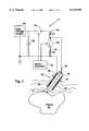
- FIG. 1shows a preferred embodiment of the present invention in use cutting tissue.
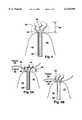
- FIG. 2shows a closeup view of a probe tip of the present invention.
- FIG. 3shows a characterization of electrical pulses according to the method of the present invention.
- FIG. 4shows the probe tip while an electrical pulse is applied to the probe.
- FIGS. 5A-5Bshow different modes of using the present invention.
- FIG. 6Ashows a characterization of electrical pulses of the present invention in terms of power.
- FIG. 6Bshows a second characterization of electrical pulses of the present invention in terms of power.
- FIG. 7shows a second embodiment of the present invention for producing electrical pulses.
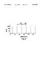
- FIG. 8shows a power versus time plot of a pulse train according to the present invention.
- the present inventionprovides methods for cutting tissues in liquid media using short duration electrical discharges.
- the electrical discharges usedhave sufficient power dissipated from a sufficiently small electrode surface so that plasma streamers are produced which extend from the electrode surface.
- the plasma streamersare produced in the tissue or liquid medium surrounding the tissue.
- the plasma streamersionize and evaporate tissue (or liquid), thereby producing high pressure shock and acoustic waves.
- the high temperature of the plasma streamers and the shock waves producedprovide effective cutting of tissue.
- the electrode surfaceis preferably in contact with the tissue being cut, but can also be spaced apart from the tissue being cut.
- the present inventionuses DC electrical pulses.
- FIG. 1shows a preferred electrical circuit 21 for performing the method of the present invention.
- the apparatushas a high voltage supply 20.
- the supply 20provides 2-10 kilovolts, for example.
- the voltage supply 20is connected to a capacitor 22 (e.g. at least 10-50 picofarads) and a high speed, high voltage discharge switch 24.
- the discharge switchis connected to a discharge resistor (R1) 26, a shunt switch 28, a shunt resistor (R2) 30, and an electrosurgical probe 32.
- the discharge switch 24 and shunt switch 28are controlled by switch controller 34.
- the electrosurgical probe 32is shown in contact with tissue 36 to be electrosurgically cut.
- the tissue 36 to be cutis surrounded by conductive liquid media 35 such as tissue fluid, intraocular fluid, or other physiological liquids.
- the liquid 35may be present in a thin layer (e.g. less than 0.1 mm thick) covering the tissue 36.
- Probe 34has two electrodes: an inner electrode 38 and a coaxial outer electrode 40.
- the inner electrode and outer electrodeare separated by a dielectric material 42 such as glass or fused silica.
- the outer electrode 40has a much larger surface area compared to inner electrode 38.
- the liquid media 35is in contact with the outer electrode 40.
- Outer electrodeis always connected to ground.
- the probehas a tip 37 where the inner electrode 38 is not covered by dielectric material 42.
- the probehas a diameter 41 of about 1.0 mm, tapering to 0.2 mm near the tip 37.
- the probe 32may have a non-coaxial geometry such as two electrodes with comparable exposed surface areas embedded in insulating material. Many electrosurgical probes are known in the art.
- the outer electrode 40can also be in contact with the tissue 36. This would be the case, for example, if the probe were fully inserted into the tissue 36. Physical contact with media 35 or tissue 36 provides electrical contact with media 35 or tissue 36.
- FIG. 2shows a closeup view of the probe tip 37.
- the inner electrode 38 and dielectric material 42are shown.
- the inner electrodehas an endface 60.
- the endfaceis preferably about 10-30 microns across 62.
- the endfacemay have an exposed surface area of about 600 microns 2 , for example.
- the inner electrode 38can be a cylindrical wire, for example, in which case endface 60 is circular.
- the inner electrodeis eroded by ablation.
- a larger endfaceprovides a longer probe lifetime because more inner electrode material must be eroded before probe is no longer useful.
- a larger endfacealso generally requires more powerful electrical pulses.
- a smaller endfacehas a shorter lifetime because it is eroded faster. However, a smaller endface can be used with less powerful electrical pulses.
- switches 24, 28can switch in less than 50 nanoseconds (switching times less than 10 ns are preferred)
- switches 24, 28are solid state switches. Solid state switches appropriate for use in the present invention are available from Eurotek, Inc, located in Morganville, N.J.
- shunt resistor 30 R2has a resistance much lower (e.g. an order of magnitude lower) than the resistance between inner 38 and outer 40 electrodes during an electrical discharge.
- on-state resistance (during plasma generation) between electrodes 38, 40is about 3 kOhm and the shunt resistor R2 is about 300 Ohm.
- Discharge resistor 26 and shunt resistor 30have a resistance selected to protect the discharge switch 24 and shunt switch 28 from excessive current.
- the lowest resistance values of the resistors 26, 30is set by the maximum current limit of the switches. This is a particular concern in embodiments where switches 24, 28 are solid state switches.
- switches 24, 28are operated alternately.
- FIG. 1shows the discharge switch 24 in a closed or conductive state, and the shunt switch 28 in an open or nonconductive state. Switches 24, 28 are only in the state shown while a pulse is being applied to the tissue. During time periods between pulses, the shunt switch 28 is closed, and discharge switch 24 is open.
- the present apparatuscuts tissue by applying short duration (i.e. less than 300 nanoseconds), high voltage pulses (i.e. greater than 1.5 kV) to the inner electrode.
- the pulsesare created by simultaneously closing discharge switch 24 and opening shunt switch 28. Opening and closing of the switches 24, 28 is controlled by the switch controller 34.
- the discharge switchis closed, and the shunt switch is open.
- the pulseis actively terminated by opening discharge switch and closing shunt switch.
- the low resistance of the shunt resistor 30 compared to the on-state (i.e. with plasma present) resistanceprovides that the pulse is quickly terminated.
- Active termination of the pulseis greatly preferred in the present invention. Active termination of the pulse assures that the pulse is stopped abruptly before exceeding 300 ns.
- FIG. 3shows a Voltage vs. Time plot of the voltage as measured at the probe electrodes 38, 40 during a single rectangular pulse 53.
- the pulse 53has a V-risetime 46 and a V-falltime 48.
- the V-risetime and V-falltimeapply only to Voltage vs. Time plots.
- the V-risetime 46is defined as the time required for the voltage to change from essentially 0 Volts (e.g. 100 volts) to 1.5 kV;
- the V-falltime 48is defined as the time required for the voltage to change from 1.5 kV to essentially 0 Volts (e.g. 100 volts).
- a pulse V-duration 54is defined as the duration the pulse exceeds 1.5 kV at the probe electrodes 38, 40.
- the voltage pulsehas a somewhat rectangular shape as shown, with the voltage maintaining a plateau voltage for most of the pulse duration.
- the plateau voltageis about 5 kV
- the V-risetime and V-falltimeare about 5 nanoseconds
- the pulse V-duration 54is about 80 nanoseconds.
- the short falltimeis due to the fast closing time of the shunt switch 28 and low resistance of shunt resistor R2.
- Falltime of the pulseis determined by discharge of the internal capacitance of the probe (about 10 pF) through R2, and by discharge of the internal capacitance of discharge switch 24 (about 20 pF) through R1+R2.
- R1+R2 resistance of about 600 Ohmsprovides a V-falltime of about 15 ns.
- the voltagecan change during the pulse duration so that a plateau voltage is not well defined.
- the voltage pulsecan even have a peaked shape or any other shape, provided that the pulse exceeds 1.5 kV.
- Peaked pulse 55for example, has approximately the same V-duration and V-risetime and V-falltime as rectangular pulse 53, and is well within the scope of the present invention.
- the plateau voltageis somewhat less than the voltage provided by the high voltage supply 20.
- the actual plateau (or peak) voltage measured at the inner electrodedepends greatly upon the impedance of the tissue during plasma formation, and the impedance of the circuit and probe. Therefore, in order to generate a desired voltage at the endface, the voltage of the high voltage source must be considerably higher than the desired endface voltage (e.g. sometimes 50-100% higher).
- the voltage pulsepreferably has a plateau or peak voltage between 2 kV and 15 kV.
- the V-risetimeis less than 100 nanoseconds, preferably less than 50 nanoseconds.
- the V-falltimeis less than 200 nanoseconds, preferably less than 100 nanoseconds, most preferably less than 50 nanoseconds.
- the pulse V-duration 54is less than 300 nanoseconds. More preferably, the pulse duration is less than 150 nanoseconds, and most preferably, the pulse duration is less than 100 nanoseconds. Pulse duration can even be limited to less than 50 or 25 nanoseconds to yield exceptionally advantageous results (i.e. efficient cutting of tissue and reduced side effects from cavitation bubbles). It is noted that, for shorter pulse duration, the voltage must be higher to provide the same tissue cutting efficacy.
- a series of pulsesare applied to tissue being cut. Pulses are applied at a frequency of about 1-10000 Hz. Since the pulses are so short, this corresponds to a duty cycle much less than 0.1%. More preferably, the pulses are applied at a rate in the range of about 10-50 Hertz. It is important to note that, in the present invention, essentially zero charge (i.e. less than 1% of the charge delivered in a single pulse) passes through the probe electrodes 38, 40 between pulses. This prevents the formation of bubbles (e.g. oxygen or hydrogen bubbles) at the endface 60. This is desirable because the presence of a bubble on the endface results in plasma formation inside the bubble, instead of in the tissue 36 or liquid medium 35. Plasma formation inside the gas bubble strongly reduces pressures and expansion velocity of the overheated liquid or tissue, thereby resulting in reduced tissue cutting efficacy.
- bubblese.g. oxygen or hydrogen bubbles
- FIG. 4shows a view of the probe tip during an electrical pulse.
- the probe tipis surrounded by tissue 36 or liquid media 35.
- Plasma streamers 64extend from the endface 60.
- the plasma streamers 64extend from the endface a distance 66 which may be about 20-100 microns (a good depth range for many intraocular surgical procedures).
- the plasma streamers 64can ionize, evaporate and destroy tissue in a very small region surrounding endface 60.
- cuttingis provided mostly by the extremely hot plasma streamers 64.
- the plasma streamers 64provide cutting action without causing excessive collateral damage to surrounding tissues.
- the plasma streamers 64are accompanied by rapidly expanding vapor and a shock wave 68 which travels in all directions away from the endface 60.
- the shock wavehelps provide cutting action.
- pulse durationshould be limited to the time required for the shock wave to leave the vicinity of where energy is deposited (i.e. the vicinity of the plasma streamers). For example, for 50 micron long plasma streamers, the pulse duration should be limited to about 50 ns, assuming that the shock wave velocity is close to the speed of sound in water, 1000 m/s.
- shock wavesare a particular advantage when cutting hard tissues such as lenses, lens capsules, and irises. Therefore, when cutting hard tissues, it is best to use relatively short (i.e. less than 75 nanosecond) pulses so that strong shock waves are generated.
- FIG. 5Ashows a method of the present invention in which the probe tip 37 is held away from the tissue 36 by a small distance 80 when the electrical pulse is applied to the probe.
- Liquid medium 35e.g. physiological fluid
- the tissue 36can be cut even though the endface 60 is not in direct contact with the tissue. This is because the distance 80 is small enough such that plasma streamers 64 and the shock wave 68 propagate into the tissue 36.
- plasma streamerscan efficiently cut the tissue 36 if the distance 80 is less than about 200 microns.
- FIG. 5Bshows a method where the endface 60 is in direct contact with tissue.
- the outer electrode 40(not shown) is in contact with the liquid media 35, but not in contact with the tissue 36.
- the method of FIG. 5Bgenerally provides deeper cutting than the method of FIG. 5A for the same pulse parameters.
- the length and distribution of the plasma streamers 64depends upon the voltage applied, pulse duration, and the surface area of the endface.
- very small endface surface arearesults in rapid etching of the endface and reduced probe lifetime. Therefore, an optimal endface size depends upon application (energy per pulse and required lifetime of the probe). Generally, circular endfaces having a diameter from a few microns to several tens of microns are preferred.
- the length of the plasma streamerscan reach about 100 microns, and further increases in plasma voltage or pulse duration results in branching of the plasma streamers (as shown in FIG. 4).
- the depth of the cut in tissuemay exceed the length of the plasma streamers, depending on tissue properties. Generally, the softer the tissue, the deeper the cut beyond the plasma streamer length.
- the rate of plasma streamer developmentdepends on applied voltage.
- the plasma streamersdevelop faster with higher voltage.
- the rate of plasma streamer developmentis measured by the time required for the resistance between inner and outer electrodes to change from a high value (e.g. 12-15 kOhm) for ionic conduction to a low value (e.g. 2-5 kOhm) for plasma conduction.
- a high to low resistance 90%-10% transition timeis about 110 ns
- at 5 kVthe high to low resistance 90%-10% transition time is 12 ns. Therefore, with higher applied voltages, the same size plasma streamer is generated with shorter pulses. This increases the mechanical confinement of the shock wave, thus increasing cutting efficiency.
- the short V-duration (i.e. less than 200 nanoseconds) of the pulses of the present inventionprovides a very important benefit.
- the short pulse durationprovides exceptionally efficient cutting of tissue for a given amount of energy applied. This is because of fast ionization due to high electric fields near the endface, as well as efficient shock wave formation.
- Energy-efficient cuttingprovides relatively high cutting power for a given cavitation bubble size (which is determined by pulse energy). Therefore the short pulses of the present invention provide effective cutting with less collateral damage to surrounding tissues. Active termination of the electrical pulses assures that the electrical pulses do not exceed a maximum desired duration.
- cavitation bubblescan only cut very soft tissues.
- the method of the present inventionuses plasma to provide cutting. Plasma can cut much harder and more dense tissues than cavitation bubbles, while producing less collateral damage. Plasma cutting is enhanced, and cavitation bubble effects are attenuated by using short (i.e. less than 200 nanosecond), high peak power pulses (i.e. greater than 1000 Watts).
- Closing the shunt switch 28guarantees that voltage is not applied for a duration longer than desired.
- the shunt switch 28assures that the pulse duration is not defined by an excessively long exponential decay constant (e.g. hundreds of nanoseconds).
- the voltage at the endfacewill be influenced by capacitance and inductance between the shunt switch and probe tip.
- impedance matching between circuit 21, probe 32 and plasma streamers 64is a concern.
- the impedance of the tissue 36 between inner electrode 38 and outer electrode 40is about 2-5 kOhms during plasma streamer discharge. Therefore, for impedance matching, a transmission line having a characteristic impedance of 2-5 kOhms can be connected between the probe 32 and circuit 21.
- 1.5 kVis generally the preferred minimum voltage for the method of the present invention because 1.5 kV is typically the minimum voltage required for ionization and plasma streamer formation in tissue using sub-microsecond pulses.
- 15 kVis the preferred maximum voltage because it is difficult to rapidly switch voltages greater than 15 kV; also, components capable of switching voltages greater than 15 kV are relatively costly.
- Voltages greater than 15 kVcan be used in the present method if a fast and inexpensive switching device, flexible HV cables and proper microelectrode materials are provided. It is noted that, for high voltages, the pulse duration should be shortened. Therefore, if very high voltages are used (i.e. greater than 15 kV), then the switches must be able to produce shorter duration pulses.
- the pulse durationshould scale as 1/V 2 , where V is pulse voltage. This assumes that the resistance of the discharge is the same at different voltages. However, the resistance tends to decrease with increasing voltage (as well as pulse duration), thereby requiring that the pulse duration be further shortened to preserver constant per-pulse energy.
- the electrical pulses of the present inventioncan also be characterized in terms of power dissipated in the tissue. In some cases, describing the pulses in terms of power is a more useful characterization.
- FIG. 6Ashows a semilogarithmic plot of Power vs. Time for a pulse according to a preferred embodiment of the present invention.
- the pulsehas a P-risetime 74, a P-falltime 76, and a nonzero P-duration 78 above 500 watts.
- the P-risetime, P-falltime, and P-durationapply only to Power vs. Time plots.
- the P-risetimeis the time required for the pulse to change from 50 Watts to 500 Watts.
- the P-falltimeis the time required for the pulse to change from 500 Watts to 50 Watts.
- the P-risetimeis less than 100 nanoseconds, preferably less than 75 or 50 nanoseconds.
- the P-falltimeis less than 150 nanoseconds, preferably less than 75 or 50 nanoseconds.
- the power dissipationpreferably falls to 1 Watt or less, most preferably to essentially zero Watts.
- the power dissipationfalls from 50 Watts to less than 1 Watt within 100 nanoseconds. This prevents the formation of gas bubbles on the endface 60 between electrical pulses.
- the P-duration 78is less than 300 nanoseconds. More preferably, the P-duration 78 is less than 200, 150, or even 75 nanoseconds. Short durations are preferred. Short duration pulses provide more effective cutting and less collateral damage to surrounding tissues.
- the risetimes and falltimescan also be defined in terms of changes between 800 Watts and 50 Watts.
- 500 Wattsis the minimum power dissipation because 500 Watts is approximately a lower limit for plasma streamer formation which provides reasonably effective cutting.
- Higher powerse.g. 800, 1000 or 1500 Watts
- pulsescan have a shorter duration and still provide equally effective cutting.
- the duration 78can also be defined in terms of these high power levels.
- the threshold for plasma streamer formationdepends somewhat on the endface 60 surface area. More specifically, 500 Watts is the plasma streamer formation threshold for a circular endface of 25 microns diameter. The threshold for plasma streamer formation will be somewhat higher for larger surface area endfaces 60. The threshold for plasma streamer formation will be somewhat lower for smaller surface area endfaces 60. This is because a large endface tends to conduct current with normal, ionic conduction, thereby reducing the power available for plasma streamer formation.
- FIG. 6Billustrates another characterization of the present method.
- a linear plot of pulse power versus timeis shown.
- the pulsehas a peak power dissipation 110 (in this specific example, the peak is slightly in excess of 2000 Watts).
- the peak 110defines a 90%-of-peak level 112 and a 10%-of-peak level 114.
- the pulsehas a 10%-to-90% risetime 116 of less than 100 nanoseconds.
- the risetimeis much less than 100 nanoseconds (e.g. less than 50 nanoseconds).
- the pulsehas a 90%-to-10% falltime 118 of less than 200 nanoseconds.
- the power dissipationis greater than 500 Watts for a duration less than 300 nanoseconds.
- the duration above 500 Wattsis less than 200 or 150 nanoseconds.
- the pulsecan also have a peak greater than 800 Watts, 1000 Watts, or 1500 Watts.
- the peak power dissipation 110depends upon the application. For cutting relatively soft tissues, peak 110 should be relatively low; for cutting hard tissues, peak 110 should be relatively high. For example, for cutting lenses or lens capsules, peak power may be greater than 2000 Watts.
- FIG. 7shows an alternative embodiment of a circuit 90 according to the present invention.
- the circuit 90does not have the shunt switch 28, but only a shunt resistor 92.
- the shunt resistor 92should have a resistance lower than the normal resistance (due to ionic conduction) between inner and outer electrodes (about 12-15 kOhms when a 25 micron diameter endface is used), and comparable with the resistance of the plasma streamer discharge (about 3 kOhm).
- the shunt resistor 92can be about 2-4 kOhms.
- a shunt resistorstrongly reduces the power dissipation and shortens the risetime and falltime of the discharge, but does not strongly effect the plasma streamer development.
- circuit 90produces pulses with relatively long falltimes compared to circuit 21. However, circuit 90 may be preferably for many applications because of lower cost as a result of requiring only one switch.
- FIG. 8shows a plot of power vs. time for a pulse train according to the present invention.
- the pulse train shownhas a frequency of about 100 Hz, but can have a frequency anywhere in the range of about 1-10000 Hz.
- a pulse trainprovides essentially continuous cutting.
- the pulsesare so short that they appear as spikes in the plot of FIG. 8.
- the power dissipation in durations 100 between pulsesis so low that the pulse train has an average power dissipation less than 0.2 Watts, more preferably less than 0.05 Watts or less than 0.01 Watts.
- the present inventionis particularly well suited for use in microsurgical procedures such as intraocular surgery.
- the present inventioncan be used in retinal surgery, cataract surgery, capsulotomy, irridotomy, as well as other intraocular surgical procedures.
- the following examplesare useful pulser settings for different surgical procedures.
- the settingsare not necessarily optimized, and may be improved.
- the endfaceis circular and 25 microns in diameter.
- Pulse peak power520 W
Landscapes
- Health & Medical Sciences (AREA)
- Surgery (AREA)
- Life Sciences & Earth Sciences (AREA)
- Engineering & Computer Science (AREA)
- Medical Informatics (AREA)
- Molecular Biology (AREA)
- Nuclear Medicine, Radiotherapy & Molecular Imaging (AREA)
- Veterinary Medicine (AREA)
- Biomedical Technology (AREA)
- Heart & Thoracic Surgery (AREA)
- Public Health (AREA)
- Otolaryngology (AREA)
- Animal Behavior & Ethology (AREA)
- General Health & Medical Sciences (AREA)
- Physics & Mathematics (AREA)
- Plasma & Fusion (AREA)
- Surgical Instruments (AREA)
- Laser Surgery Devices (AREA)
- Radiation-Therapy Devices (AREA)
- Pharmaceuticals Containing Other Organic And Inorganic Compounds (AREA)
Abstract
Description
Claims (47)
Priority Applications (7)
| Application Number | Priority Date | Filing Date | Title |
|---|---|---|---|
| US09/270,401US6135998A (en) | 1999-03-16 | 1999-03-16 | Method and apparatus for pulsed plasma-mediated electrosurgery in liquid media |
| PCT/US2000/004688WO2000054683A1 (en) | 1999-03-16 | 2000-02-23 | Method and apparatus for pulsed plasma-mediated electrosurgery in liquid media |
| AU37059/00AAU3705900A (en) | 1999-03-16 | 2000-02-23 | Method and apparatus for pulsed plasma-mediated electrosurgery in liquid media |
| JP2000604767AJP2002538881A (en) | 1999-03-16 | 2000-02-23 | Method and apparatus for pulsed plasma electrosurgery in a liquid medium |
| EP00915856AEP1079754B1 (en) | 1999-03-16 | 2000-02-23 | Apparatus for pulsed plasma-mediated electrosurgery in liquid media |
| AT00915856TATE330546T1 (en) | 1999-03-16 | 2000-02-23 | DEVICE FOR ELECTROSURGERY IN A LIQUID ENVIRONMENT USING PLASMA PULSE |
| DE60028887TDE60028887T2 (en) | 1999-03-16 | 2000-02-23 | DEVICE FOR ELECTRO-SURGERY IN A LIQUID ENVIRONMENT USING PLASMA PULSES |
Applications Claiming Priority (1)
| Application Number | Priority Date | Filing Date | Title |
|---|---|---|---|
| US09/270,401US6135998A (en) | 1999-03-16 | 1999-03-16 | Method and apparatus for pulsed plasma-mediated electrosurgery in liquid media |
Publications (1)
| Publication Number | Publication Date |
|---|---|
| US6135998Atrue US6135998A (en) | 2000-10-24 |
Family
ID=23031197
Family Applications (1)
| Application Number | Title | Priority Date | Filing Date |
|---|---|---|---|
| US09/270,401Expired - LifetimeUS6135998A (en) | 1999-03-16 | 1999-03-16 | Method and apparatus for pulsed plasma-mediated electrosurgery in liquid media |
Country Status (7)
| Country | Link |
|---|---|
| US (1) | US6135998A (en) |
| EP (1) | EP1079754B1 (en) |
| JP (1) | JP2002538881A (en) |
| AT (1) | ATE330546T1 (en) |
| AU (1) | AU3705900A (en) |
| DE (1) | DE60028887T2 (en) |
| WO (1) | WO2000054683A1 (en) |
Cited By (98)
| Publication number | Priority date | Publication date | Assignee | Title |
|---|---|---|---|---|
| US6547794B2 (en) | 2000-08-18 | 2003-04-15 | Auge', Ii Wayne K. | Method for fusing bone during endoscopy procedures |
| US6579270B2 (en) | 1998-06-04 | 2003-06-17 | Alcon Manufacturing, Ltd. | Liquefracture handpiece tip |
| US20030136756A1 (en)* | 2002-01-18 | 2003-07-24 | Leclair Mark L. | Method and apparatus for the controlled formation of cavitation bubbles using target bubbles |
| WO2003015865A3 (en)* | 2001-08-15 | 2003-08-07 | Wayne K Ii Auge | Methods and devices for electrosurgery |
| US6620160B2 (en)* | 1996-09-26 | 2003-09-16 | Nanoptics, Inc. | Method and device for electro microsurgery in a physiological liquid environment |
| US20040004055A1 (en)* | 2002-01-18 | 2004-01-08 | Barros Emanuel F. | Method and apparatus for the controlled formation of cavitation bubbles |
| US20040030349A1 (en)* | 2002-08-08 | 2004-02-12 | Mikhail Boukhny | Liquefaction handpiece tip |
| US6723091B2 (en)* | 2000-02-22 | 2004-04-20 | Gyrus Medical Limited | Tissue resurfacing |
| US6730075B2 (en) | 2001-10-12 | 2004-05-04 | The Board Of Trustees Of The Leland Stanford Junior University | Surgical probe for use in liquid media |
| US6749603B2 (en)* | 2001-04-07 | 2004-06-15 | Carl Zeiss Jena Gmbh | Electrical probe |
| US6761694B2 (en) | 2001-12-13 | 2004-07-13 | Allergan, Inc. | Methods for measuring retinal damage |
| US20040186470A1 (en)* | 2000-02-22 | 2004-09-23 | Gyrus Medical Limited | Tissue resurfacing |
| US20040199157A1 (en)* | 2002-05-03 | 2004-10-07 | Palanker Daniel V. | Method and apparatus for plasma-mediated thermo-electrical ablation |
| US20040236321A1 (en)* | 2003-02-14 | 2004-11-25 | Palanker Daniel V. | Electrosurgical system with uniformly enhanced electric field and minimal collateral damage |
| US6867387B2 (en) | 1998-07-09 | 2005-03-15 | Richard J. Fugo | Device for plasma incision of matter with a specifically tuned radiofrequency electromagnetic field generator |
| US20050085806A1 (en)* | 2002-06-06 | 2005-04-21 | Map Technologies, Llc | Methods and devices for electrosurgery |
| US20050149012A1 (en)* | 2000-02-22 | 2005-07-07 | Gyrus Medical Limited | Tissue resurfacing |
| US20050187542A1 (en)* | 2000-08-18 | 2005-08-25 | Map Technologies, Llc | Devices for electrosurgery |
| DE102005013714A1 (en)* | 2004-04-07 | 2005-12-22 | Carl Zeiss Meditec Ag | Electrical probe for microsurgery |
| US6979328B2 (en) | 2001-01-18 | 2005-12-27 | The Regents Of The University Of California | Minimally invasive glaucoma surgical instrument and method |
| US20060009763A1 (en)* | 2000-02-22 | 2006-01-12 | Rhytech Limited | Tissue treatment system |
| US20060100617A1 (en)* | 2004-11-09 | 2006-05-11 | Alcon, Inc. | Capsularhexis device |
| US20060116674A1 (en)* | 2000-02-22 | 2006-06-01 | Rhytec Limited | Method of regenerating the recticular architecture of the dermis |
| US20060212038A1 (en)* | 2005-03-16 | 2006-09-21 | Alcon, Inc. | Liquefaction handpiece tip |
| USRE39358E1 (en) | 1999-05-21 | 2006-10-17 | Gyrus Medical Limited | Electrosurgery system and method |
| RU2285492C2 (en)* | 2004-12-21 | 2006-10-20 | Мария Юрьевна Шарафутдинова | Device for cold radio-frequency ablation |
| US20070027446A1 (en)* | 2000-02-22 | 2007-02-01 | Rhytec Limited | Method of removing a tattoo |
| US20070073287A1 (en)* | 2000-02-22 | 2007-03-29 | Rhytec Limited | Method of remodelling stretch marks |
| US20070156129A1 (en)* | 2006-01-03 | 2007-07-05 | Alcon, Inc. | System For Dissociation and Removal of Proteinaceous Tissue |
| US20080045941A1 (en)* | 2006-08-17 | 2008-02-21 | Fugo Richard J | Method and apparatus for plasma incision of cardiovascular tissue |
| US20080119842A1 (en)* | 2003-06-18 | 2008-05-22 | The Board Of Trustees Of The Leland Stanford Junior University | Electro-adhesive tissue manipulation method |
| US20080167604A1 (en)* | 2007-01-09 | 2008-07-10 | Alcon, Inc. | Irrigation/Aspiration Tip |
| WO2008057410A3 (en)* | 2006-11-02 | 2008-07-17 | Peak Surgical Inc | Electric plasma-mediated cutting and coagulation of tissue and surgical apparatus |
| US20100026186A1 (en)* | 2008-07-31 | 2010-02-04 | Advanced Energy Industries, Inc. | Power supply ignition system and method |
| US20100087815A1 (en)* | 2001-08-15 | 2010-04-08 | Nuortho Surgical Inc. | Electrosurgical Plenum |
| WO2010022160A3 (en)* | 2008-08-19 | 2010-04-15 | Drexel University | Nano discharges in liquids |
| US20100140231A1 (en)* | 2008-12-05 | 2010-06-10 | Milan Ilic | Arc recovery with over-voltage protection for plasma-chamber power supplies |
| US7736361B2 (en) | 2003-02-14 | 2010-06-15 | The Board Of Trustees Of The Leland Stamford Junior University | Electrosurgical system with uniformly enhanced electric field and minimal collateral damage |
| US20100211230A1 (en)* | 2009-02-17 | 2010-08-19 | Albert Bulliard | power supply device for plasma processing |
| US7785322B2 (en) | 2000-02-22 | 2010-08-31 | Plasmogen Inc. | Tissue treatment system |
| US7819861B2 (en) | 2001-05-26 | 2010-10-26 | Nuortho Surgical, Inc. | Methods for electrosurgical electrolysis |
| US7857794B2 (en) | 2004-06-14 | 2010-12-28 | Alcon, Inc. | Handpiece tip |
| RU2413551C2 (en)* | 2009-05-14 | 2011-03-10 | Общество с ограниченной ответственностью "Научно-производственное предприятие "Импульсные наукоемкие технологии" - ООО "НПП ИНТЕХ" | Device for influence on bioobject |
| US20110071517A1 (en)* | 2009-09-23 | 2011-03-24 | Bovie Medical Corporation | Electrosurgical system to generate a pulsed plasma stream and method thereof |
| US7928338B2 (en) | 2007-02-02 | 2011-04-19 | Plasma Surgical Investments Ltd. | Plasma spraying device and method |
| US20110118729A1 (en)* | 2009-11-13 | 2011-05-19 | Alcon Research, Ltd | High-intensity pulsed electric field vitrectomy apparatus with load detection |
| US20110118728A1 (en)* | 2009-11-13 | 2011-05-19 | Alcon Research, Ltd. | Control of high-intensity pulsed electrical fields in surgical applications |
| US7955296B1 (en) | 2001-05-26 | 2011-06-07 | Nuortho Surgical, Inc. | Biologically enhanced irrigants |
| US20110135626A1 (en)* | 2009-12-08 | 2011-06-09 | Alcon Research, Ltd. | Localized Chemical Lysis of Ocular Tissue |
| US20110144562A1 (en)* | 2009-12-14 | 2011-06-16 | Alcon Research, Ltd. | Localized Pharmacological Treatment of Ocular Tissue Using High-Intensity Pulsed Electrical Fields |
| US20110144638A1 (en)* | 2009-12-14 | 2011-06-16 | Alcon Research, Ltd. | Localized Shockwave-Induced Tissue Disruption |
| US20110144641A1 (en)* | 2009-12-15 | 2011-06-16 | Alcon Research, Ltd. | High-Intensity Pulsed Electric Field Vitrectomy Apparatus |
| US8030849B2 (en) | 2007-08-06 | 2011-10-04 | Plasma Surgical Investments Limited | Pulsed plasma device and method for generating pulsed plasma |
| US8043286B2 (en) | 2002-05-03 | 2011-10-25 | The Board Of Trustees Of The Leland Stanford Junior University | Method and apparatus for plasma-mediated thermo-electrical ablation |
| US8105325B2 (en) | 2005-07-08 | 2012-01-31 | Plasma Surgical Investments Limited | Plasma-generating device, plasma surgical device, use of a plasma-generating device and method of generating a plasma |
| US8109928B2 (en) | 2005-07-08 | 2012-02-07 | Plasma Surgical Investments Limited | Plasma-generating device, plasma surgical device and use of plasma surgical device |
| US8137344B2 (en) | 2008-12-10 | 2012-03-20 | Alcon Research, Ltd. | Flexible, automated capsulorhexis device |
| US8157797B2 (en) | 2009-01-12 | 2012-04-17 | Alcon Research, Ltd. | Capsularhexis device with retractable bipolar electrodes |
| US8235979B2 (en) | 2001-08-15 | 2012-08-07 | Nuortho Surgical, Inc. | Interfacing media manipulation with non-ablation radiofrequency energy system and method |
| US8348938B2 (en) | 2008-05-06 | 2013-01-08 | Old Dominian University Research Foundation | Apparatus, systems and methods for treating a human tissue condition |
| US8546979B2 (en) | 2010-08-11 | 2013-10-01 | Alcon Research, Ltd. | Self-matching pulse generator with adjustable pulse width and pulse frequency |
| US8551088B2 (en) | 2008-03-31 | 2013-10-08 | Applied Medical Resources Corporation | Electrosurgical system |
| US8552665B2 (en) | 2010-08-20 | 2013-10-08 | Advanced Energy Industries, Inc. | Proactive arc management of a plasma load |
| US8613742B2 (en) | 2010-01-29 | 2013-12-24 | Plasma Surgical Investments Limited | Methods of sealing vessels using plasma |
| US8632537B2 (en) | 2009-01-05 | 2014-01-21 | Medtronic Advanced Energy Llc | Electrosurgical devices for tonsillectomy and adenoidectomy |
| US8735766B2 (en) | 2007-08-06 | 2014-05-27 | Plasma Surgical Investments Limited | Cathode assembly and method for pulsed plasma generation |
| US8734441B2 (en) | 2001-08-15 | 2014-05-27 | Nuortho Surgical, Inc. | Interfacing media manipulation with non-ablation radiofrequency energy system and method |
| USD707818S1 (en) | 2013-03-05 | 2014-06-24 | Alcon Research Ltd. | Capsulorhexis handpiece |
| US8814854B2 (en) | 2009-06-03 | 2014-08-26 | Alcon Research, Ltd. | Capsulotomy repair device and method for capsulotomy repair |
| US8979842B2 (en) | 2011-06-10 | 2015-03-17 | Medtronic Advanced Energy Llc | Wire electrode devices for tonsillectomy and adenoidectomy |
| US9084606B2 (en) | 2012-06-01 | 2015-07-21 | Megadyne Medical Products, Inc. | Electrosurgical scissors |
| CZ305304B6 (en)* | 2014-04-29 | 2015-07-22 | Vysoké Učení Technické V Brně | Nozzle system for generating plasma in liquids |
| US9089319B2 (en) | 2010-07-22 | 2015-07-28 | Plasma Surgical Investments Limited | Volumetrically oscillating plasma flows |
| USD737438S1 (en) | 2014-03-04 | 2015-08-25 | Novartis Ag | Capsulorhexis handpiece |
| US9125720B2 (en) | 2008-10-13 | 2015-09-08 | Alcon Research, Ltd. | Capsularhexis device with flexible heating element |
| US9149388B2 (en) | 2010-09-29 | 2015-10-06 | Alcon Research, Ltd. | Attenuated RF power for automated capsulorhexis |
| US9241755B2 (en) | 2010-05-11 | 2016-01-26 | Alcon Research, Ltd. | Capsule polishing device and method for capsule polishing |
| USD748259S1 (en) | 2014-12-29 | 2016-01-26 | Applied Medical Resources Corporation | Electrosurgical instrument |
| US9320563B2 (en) | 2010-10-01 | 2016-04-26 | Applied Medical Resources Corporation | Electrosurgical instruments and connections thereto |
| US9387269B2 (en) | 2011-01-28 | 2016-07-12 | Bovie Medical Corporation | Cold plasma jet hand sanitizer |
| US9408658B2 (en) | 2011-02-24 | 2016-08-09 | Nuortho Surgical, Inc. | System and method for a physiochemical scalpel to eliminate biologic tissue over-resection and induce tissue healing |
| US9532827B2 (en) | 2009-06-17 | 2017-01-03 | Nuortho Surgical Inc. | Connection of a bipolar electrosurgical hand piece to a monopolar output of an electrosurgical generator |
| US9579142B1 (en) | 2012-12-13 | 2017-02-28 | Nuortho Surgical Inc. | Multi-function RF-probe with dual electrode positioning |
| US9681907B2 (en) | 2010-01-28 | 2017-06-20 | Bovie Medical Corporation | Electrosurgical apparatus to generate a dual plasma stream and method thereof |
| EP3285059A1 (en)* | 2009-05-27 | 2018-02-21 | Micromass UK Limited | System and method for identification of biological tissues |
| US9913358B2 (en) | 2005-07-08 | 2018-03-06 | Plasma Surgical Investments Limited | Plasma-generating device, plasma surgical device and use of a plasma surgical device |
| US10149713B2 (en) | 2014-05-16 | 2018-12-11 | Applied Medical Resources Corporation | Electrosurgical system |
| US20190142407A1 (en)* | 2017-11-14 | 2019-05-16 | Endovision Co., Ltd. | Method of unilateral biportal endoscopy and diamond shaver used in same |
| US10420603B2 (en) | 2014-12-23 | 2019-09-24 | Applied Medical Resources Corporation | Bipolar electrosurgical sealer and divider |
| US10792092B2 (en) | 2014-05-30 | 2020-10-06 | Applied Medical Resources Corporation | Electrosurgical seal and dissection systems |
| US10952785B2 (en) | 2016-08-01 | 2021-03-23 | Medtronic Advanced Energy, Llc | Device for medical lead extraction |
| US20220031387A1 (en)* | 2020-07-28 | 2022-02-03 | Biosense Webster (Israel) Ltd. | Cautious irreversible-electroporation (ire) protocol for avoiding bubble generation |
| WO2022138290A1 (en) | 2020-12-25 | 2022-06-30 | 朝日インテック株式会社 | Plasma ablasion system and plasma guide wire |
| IL260233B1 (en)* | 2017-07-06 | 2023-03-01 | Biosense Webster Israel Ltd | Temperature controlled short duration ablation with multiple electrodes |
| US11696796B2 (en) | 2018-11-16 | 2023-07-11 | Applied Medical Resources Corporation | Electrosurgical system |
| US11864812B2 (en) | 2018-09-05 | 2024-01-09 | Applied Medical Resources Corporation | Electrosurgical generator control system |
| US11882643B2 (en) | 2020-08-28 | 2024-01-23 | Plasma Surgical, Inc. | Systems, methods, and devices for generating predominantly radially expanded plasma flow |
| US11883089B2 (en) | 2016-11-14 | 2024-01-30 | Medtronic, Inc. | Controlled optical properties vitreous enamel composition for electrosurgical tool |
Families Citing this family (23)
| Publication number | Priority date | Publication date | Assignee | Title |
|---|---|---|---|---|
| US7137980B2 (en) | 1998-10-23 | 2006-11-21 | Sherwood Services Ag | Method and system for controlling output of RF medical generator |
| US6843789B2 (en) | 2000-10-31 | 2005-01-18 | Gyrus Medical Limited | Electrosurgical system |
| GB0026586D0 (en)* | 2000-10-31 | 2000-12-13 | Gyrus Medical Ltd | An electrosurgical system |
| US6893435B2 (en) | 2000-10-31 | 2005-05-17 | Gyrus Medical Limited | Electrosurgical system |
| DE10249674B4 (en)* | 2002-10-24 | 2014-12-24 | Carl Zeiss Meditec Ag | Surgical instrument for cutting, ablating or aspirating material in an operating area |
| CN1323649C (en) | 2003-01-09 | 2007-07-04 | 盖拉斯医疗有限公司 | electrosurgical generator |
| US7195627B2 (en) | 2003-01-09 | 2007-03-27 | Gyrus Medical Limited | Electrosurgical generator |
| US7396336B2 (en) | 2003-10-30 | 2008-07-08 | Sherwood Services Ag | Switched resonant ultrasonic power amplifier system |
| US8394084B2 (en) | 2005-01-10 | 2013-03-12 | Optimedica Corporation | Apparatus for patterned plasma-mediated laser trephination of the lens capsule and three dimensional phaco-segmentation |
| WO2009146439A1 (en)* | 2008-05-30 | 2009-12-03 | Colorado State University Research Foundation | System, method and apparatus for generating plasma |
| US8377053B2 (en) | 2008-09-05 | 2013-02-19 | Covidien Lp | Electrosurgical apparatus with high speed energy recovery |
| US8287529B2 (en) | 2008-09-05 | 2012-10-16 | Tyco Healthcare Group Lp | Electrosurgical apparatus with high speed energy recovery |
| WO2010120866A2 (en)* | 2009-04-14 | 2010-10-21 | Old Dominion University Research Foundation | Medical instrument for delivery of high voltage pulses and method of delivering the same |
| GB2496382B (en) | 2011-11-07 | 2014-05-07 | Asalus Medical Instr Ltd | Improvements in and relating to laparoscopic instruments |
| US9529025B2 (en) | 2012-06-29 | 2016-12-27 | Covidien Lp | Systems and methods for measuring the frequency of signals generated by high frequency medical devices |
| DE102012016563A1 (en) | 2012-08-22 | 2014-02-27 | Olympus Winter & Ibe Gmbh | High frequency surgical device |
| US9872719B2 (en) | 2013-07-24 | 2018-01-23 | Covidien Lp | Systems and methods for generating electrosurgical energy using a multistage power converter |
| US9655670B2 (en) | 2013-07-29 | 2017-05-23 | Covidien Lp | Systems and methods for measuring tissue impedance through an electrosurgical cable |
| US20180368905A1 (en)* | 2015-11-30 | 2018-12-27 | Scott T. Latterell | Saline field electrosurgical system |
| WO2019191538A1 (en) | 2018-03-29 | 2019-10-03 | Asahi Intecc Co., Ltd. | Catheter and recanalization catheter system |
| US11707320B2 (en)* | 2019-12-24 | 2023-07-25 | Biosense Webster (Israel) Ltd. | Irreversible electroporation (IRE) based on field, contact force and time |
| US12226143B2 (en) | 2020-06-22 | 2025-02-18 | Covidien Lp | Universal surgical footswitch toggling |
| DE102020213290A1 (en) | 2020-10-21 | 2022-04-21 | Robert Bosch Gesellschaft mit beschränkter Haftung | Electrosurgical Instrument |
Citations (8)
| Publication number | Priority date | Publication date | Assignee | Title |
|---|---|---|---|---|
| US3903891A (en)* | 1968-01-12 | 1975-09-09 | Hogle Kearns Int | Method and apparatus for generating plasma |
| US4429694A (en)* | 1981-07-06 | 1984-02-07 | C. R. Bard, Inc. | Electrosurgical generator |
| GB2225534A (en)* | 1988-08-11 | 1990-06-06 | Kontron Holding Ag | Electrosurgical apparatus |
| US5300068A (en)* | 1992-04-21 | 1994-04-05 | St. Jude Medical, Inc. | Electrosurgical apparatus |
| US5509916A (en)* | 1994-08-12 | 1996-04-23 | Valleylab Inc. | Laser-assisted electrosurgery system |
| US5669907A (en)* | 1995-02-10 | 1997-09-23 | Valleylab Inc. | Plasma enhanced bipolar electrosurgical system |
| US5720745A (en)* | 1992-11-24 | 1998-02-24 | Erbe Electromedizin Gmbh | Electrosurgical unit and method for achieving coagulation of biological tissue |
| US5871469A (en)* | 1992-01-07 | 1999-02-16 | Arthro Care Corporation | System and method for electrosurgical cutting and ablation |
Family Cites Families (2)
| Publication number | Priority date | Publication date | Assignee | Title |
|---|---|---|---|---|
| US4030501A (en)* | 1976-01-26 | 1977-06-21 | Minnesota Mining And Manufacturing Company | High frequency-high voltage level electrosurgical unit |
| GB9626512D0 (en)* | 1996-12-20 | 1997-02-05 | Gyrus Medical Ltd | An improved electrosurgical generator and system |
- 1999
- 1999-03-16USUS09/270,401patent/US6135998A/ennot_activeExpired - Lifetime
- 2000
- 2000-02-23DEDE60028887Tpatent/DE60028887T2/ennot_activeExpired - Lifetime
- 2000-02-23ATAT00915856Tpatent/ATE330546T1/ennot_activeIP Right Cessation
- 2000-02-23WOPCT/US2000/004688patent/WO2000054683A1/enactiveIP Right Grant
- 2000-02-23AUAU37059/00Apatent/AU3705900A/ennot_activeAbandoned
- 2000-02-23EPEP00915856Apatent/EP1079754B1/ennot_activeExpired - Lifetime
- 2000-02-23JPJP2000604767Apatent/JP2002538881A/enactivePending
Patent Citations (8)
| Publication number | Priority date | Publication date | Assignee | Title |
|---|---|---|---|---|
| US3903891A (en)* | 1968-01-12 | 1975-09-09 | Hogle Kearns Int | Method and apparatus for generating plasma |
| US4429694A (en)* | 1981-07-06 | 1984-02-07 | C. R. Bard, Inc. | Electrosurgical generator |
| GB2225534A (en)* | 1988-08-11 | 1990-06-06 | Kontron Holding Ag | Electrosurgical apparatus |
| US5871469A (en)* | 1992-01-07 | 1999-02-16 | Arthro Care Corporation | System and method for electrosurgical cutting and ablation |
| US5300068A (en)* | 1992-04-21 | 1994-04-05 | St. Jude Medical, Inc. | Electrosurgical apparatus |
| US5720745A (en)* | 1992-11-24 | 1998-02-24 | Erbe Electromedizin Gmbh | Electrosurgical unit and method for achieving coagulation of biological tissue |
| US5509916A (en)* | 1994-08-12 | 1996-04-23 | Valleylab Inc. | Laser-assisted electrosurgery system |
| US5669907A (en)* | 1995-02-10 | 1997-09-23 | Valleylab Inc. | Plasma enhanced bipolar electrosurgical system |
Non-Patent Citations (2)
| Title |
|---|
| Palanker, D, Electrical alternative to pulsed fiber delivered lasers in microsurgery , J. Appl. Phys. 81(11), pp. 7673 7680, 1997.* |
| Palanker, D, Electrical alternative to pulsed fiber-delivered lasers in microsurgery, J. Appl. Phys. 81(11), pp. 7673-7680, 1997. |
Cited By (196)
| Publication number | Priority date | Publication date | Assignee | Title |
|---|---|---|---|---|
| US6620160B2 (en)* | 1996-09-26 | 2003-09-16 | Nanoptics, Inc. | Method and device for electro microsurgery in a physiological liquid environment |
| US6579270B2 (en) | 1998-06-04 | 2003-06-17 | Alcon Manufacturing, Ltd. | Liquefracture handpiece tip |
| US7173211B2 (en) | 1998-07-09 | 2007-02-06 | Rjf Holdings Ii, Inc. | Device for plasma incision of matter with a specifically tuned radiofrequency electromagnetic field generator |
| US20050173383A1 (en)* | 1998-07-09 | 2005-08-11 | Damian Coccio | Device for plasma incision of matter with a specifically tuned radiofrequency electromagnetic field generator |
| US6867387B2 (en) | 1998-07-09 | 2005-03-15 | Richard J. Fugo | Device for plasma incision of matter with a specifically tuned radiofrequency electromagnetic field generator |
| USRE39358E1 (en) | 1999-05-21 | 2006-10-17 | Gyrus Medical Limited | Electrosurgery system and method |
| USRE41921E1 (en) | 1999-05-21 | 2010-11-09 | Gyrus Medical Limited | Electrosurgery system and method |
| US6723091B2 (en)* | 2000-02-22 | 2004-04-20 | Gyrus Medical Limited | Tissue resurfacing |
| US20060009763A1 (en)* | 2000-02-22 | 2006-01-12 | Rhytech Limited | Tissue treatment system |
| US20070027446A1 (en)* | 2000-02-22 | 2007-02-01 | Rhytec Limited | Method of removing a tattoo |
| US20070073287A1 (en)* | 2000-02-22 | 2007-03-29 | Rhytec Limited | Method of remodelling stretch marks |
| US7785322B2 (en) | 2000-02-22 | 2010-08-31 | Plasmogen Inc. | Tissue treatment system |
| US20040186470A1 (en)* | 2000-02-22 | 2004-09-23 | Gyrus Medical Limited | Tissue resurfacing |
| US20060116674A1 (en)* | 2000-02-22 | 2006-06-01 | Rhytec Limited | Method of regenerating the recticular architecture of the dermis |
| US7862564B2 (en) | 2000-02-22 | 2011-01-04 | Plasmogen Inc. | Method of remodelling stretch marks |
| US20050256519A1 (en)* | 2000-02-22 | 2005-11-17 | Rhytec Limited | Tissue resurfacing |
| US7300436B2 (en) | 2000-02-22 | 2007-11-27 | Rhytec Limited | Tissue resurfacing |
| US7335199B2 (en) | 2000-02-22 | 2008-02-26 | Rhytec Limited | Tissue resurfacing |
| US20050149012A1 (en)* | 2000-02-22 | 2005-07-07 | Gyrus Medical Limited | Tissue resurfacing |
| US7713269B2 (en) | 2000-08-18 | 2010-05-11 | Nuortho Surgical, Inc. | Devices for electrosurgery |
| US7445619B2 (en) | 2000-08-18 | 2008-11-04 | Map Technologies Llc | Devices for electrosurgery |
| US20030175251A1 (en)* | 2000-08-18 | 2003-09-18 | Auge Wayne K. | Method for achieving tissue changes in bone or bone-derived tissue |
| US20050187542A1 (en)* | 2000-08-18 | 2005-08-25 | Map Technologies, Llc | Devices for electrosurgery |
| US20110034914A1 (en)* | 2000-08-18 | 2011-02-10 | Auge Ii Wayne K | Devices for Electrosurgery |
| US6547794B2 (en) | 2000-08-18 | 2003-04-15 | Auge', Ii Wayne K. | Method for fusing bone during endoscopy procedures |
| US7105011B2 (en) | 2000-08-18 | 2006-09-12 | Auge Ii Wayne K | Method for achieving tissue changes in bone or bone-derived tissue |
| US20110077626A1 (en)* | 2001-01-18 | 2011-03-31 | The Regents Of The University Of California | Minimally invasive glaucoma surgical instrument and method |
| US9226850B2 (en) | 2001-01-18 | 2016-01-05 | The Regents Of The University Of California | Minimally invasive glaucoma surgical instrument and method |
| US7785321B2 (en) | 2001-01-18 | 2010-08-31 | The Regents Of The University Of California | Minimally invasive glaucoma surgical instrument and method |
| US10085885B2 (en) | 2001-01-18 | 2018-10-02 | The Regents Of The University Of California | Minimally invasive glaucoma surgical instrument and method |
| US6979328B2 (en) | 2001-01-18 | 2005-12-27 | The Regents Of The University Of California | Minimally invasive glaucoma surgical instrument and method |
| US8512321B2 (en) | 2001-01-18 | 2013-08-20 | The Regents Of The University Of California | Minimally invasive glaucoma surgical instrument and method |
| US10744033B2 (en) | 2001-01-18 | 2020-08-18 | The Regents Of The University Of California | Minimally invasive glaucoma surgical instrument and method |
| US9999544B2 (en) | 2001-01-18 | 2018-06-19 | The Regents Of The University Of California | Minimally invasive glaucoma surgical instrument and method |
| US6749603B2 (en)* | 2001-04-07 | 2004-06-15 | Carl Zeiss Jena Gmbh | Electrical probe |
| US7955296B1 (en) | 2001-05-26 | 2011-06-07 | Nuortho Surgical, Inc. | Biologically enhanced irrigants |
| US7819861B2 (en) | 2001-05-26 | 2010-10-26 | Nuortho Surgical, Inc. | Methods for electrosurgical electrolysis |
| US7819864B2 (en) | 2001-08-15 | 2010-10-26 | Nuortho Surgical, Inc. | Electrosurgery devices |
| US8235979B2 (en) | 2001-08-15 | 2012-08-07 | Nuortho Surgical, Inc. | Interfacing media manipulation with non-ablation radiofrequency energy system and method |
| US8734441B2 (en) | 2001-08-15 | 2014-05-27 | Nuortho Surgical, Inc. | Interfacing media manipulation with non-ablation radiofrequency energy system and method |
| WO2003015865A3 (en)* | 2001-08-15 | 2003-08-07 | Wayne K Ii Auge | Methods and devices for electrosurgery |
| US6902564B2 (en) | 2001-08-15 | 2005-06-07 | Roy E. Morgan | Methods and devices for electrosurgery |
| US20100087815A1 (en)* | 2001-08-15 | 2010-04-08 | Nuortho Surgical Inc. | Electrosurgical Plenum |
| US20040267255A1 (en)* | 2001-08-15 | 2004-12-30 | Auge Ii Wayne K | Methods and devices for electrosurgery |
| US20090306645A1 (en)* | 2001-08-15 | 2009-12-10 | Nuortho Surgical Inc. | Electrosurgery Devices |
| US8591508B2 (en) | 2001-08-15 | 2013-11-26 | Nuortho Surgical, Inc. | Electrosurgical plenum |
| US6730075B2 (en) | 2001-10-12 | 2004-05-04 | The Board Of Trustees Of The Leland Stanford Junior University | Surgical probe for use in liquid media |
| US6761694B2 (en) | 2001-12-13 | 2004-07-13 | Allergan, Inc. | Methods for measuring retinal damage |
| US20040004055A1 (en)* | 2002-01-18 | 2004-01-08 | Barros Emanuel F. | Method and apparatus for the controlled formation of cavitation bubbles |
| US6932914B2 (en)* | 2002-01-18 | 2005-08-23 | Leclair Mark L. | Method and apparatus for the controlled formation of cavitation bubbles using target bubbles |
| US20030136756A1 (en)* | 2002-01-18 | 2003-07-24 | Leclair Mark L. | Method and apparatus for the controlled formation of cavitation bubbles using target bubbles |
| US7238185B2 (en) | 2002-05-03 | 2007-07-03 | The Board Of Trustees Of The Leland Stanford Junior University | Method and apparatus for plasma-mediated thermo-electrical ablation |
| US20040199157A1 (en)* | 2002-05-03 | 2004-10-07 | Palanker Daniel V. | Method and apparatus for plasma-mediated thermo-electrical ablation |
| US8043286B2 (en) | 2002-05-03 | 2011-10-25 | The Board Of Trustees Of The Leland Stanford Junior University | Method and apparatus for plasma-mediated thermo-electrical ablation |
| US7789879B2 (en) | 2002-05-03 | 2010-09-07 | Board Of Trustees Of The Leland Stanford Junior University | System for plasma-mediated thermo-electrical surgery |
| EP1539011A4 (en)* | 2002-05-03 | 2010-07-07 | Univ Leland Stanford Junior | METHOD AND APPARATUS FOR THERMO-ELECTRIC ABLATION USING PLASMA |
| US20050085806A1 (en)* | 2002-06-06 | 2005-04-21 | Map Technologies, Llc | Methods and devices for electrosurgery |
| US7771422B2 (en) | 2002-06-06 | 2010-08-10 | Nuortho Surgical, Inc. | Methods and devices for electrosurgery |
| US20040030349A1 (en)* | 2002-08-08 | 2004-02-12 | Mikhail Boukhny | Liquefaction handpiece tip |
| US20080125774A1 (en)* | 2003-02-14 | 2008-05-29 | Palanker Daniel V | Method for electrosurgery with enhanced electric field and minimal tissue damage |
| US7736361B2 (en) | 2003-02-14 | 2010-06-15 | The Board Of Trustees Of The Leland Stamford Junior University | Electrosurgical system with uniformly enhanced electric field and minimal collateral damage |
| US20040236321A1 (en)* | 2003-02-14 | 2004-11-25 | Palanker Daniel V. | Electrosurgical system with uniformly enhanced electric field and minimal collateral damage |
| US7357802B2 (en) | 2003-02-14 | 2008-04-15 | The Board Of Trustees Of The Leland Stanford Junior University | Electrosurgical system with uniformly enhanced electric field and minimal collateral damage |
| US20080119842A1 (en)* | 2003-06-18 | 2008-05-22 | The Board Of Trustees Of The Leland Stanford Junior University | Electro-adhesive tissue manipulation method |
| US7527624B2 (en) | 2004-04-07 | 2009-05-05 | Carl Zeiss Meditec Ag | Electrical probe for microsurgery |
| DE102005013714A1 (en)* | 2004-04-07 | 2005-12-22 | Carl Zeiss Meditec Ag | Electrical probe for microsurgery |
| US20060069386A1 (en)* | 2004-04-07 | 2006-03-30 | Steffen Dubnack | Electrical probe for microsurgery |
| US7857794B2 (en) | 2004-06-14 | 2010-12-28 | Alcon, Inc. | Handpiece tip |
| US20060100617A1 (en)* | 2004-11-09 | 2006-05-11 | Alcon, Inc. | Capsularhexis device |
| RU2285492C2 (en)* | 2004-12-21 | 2006-10-20 | Мария Юрьевна Шарафутдинова | Device for cold radio-frequency ablation |
| US7967799B2 (en) | 2005-03-16 | 2011-06-28 | Alcon, Inc. | Liquefaction handpiece tip |
| US20060212038A1 (en)* | 2005-03-16 | 2006-09-21 | Alcon, Inc. | Liquefaction handpiece tip |
| US8337494B2 (en) | 2005-07-08 | 2012-12-25 | Plasma Surgical Investments Limited | Plasma-generating device having a plasma chamber |
| US8465487B2 (en) | 2005-07-08 | 2013-06-18 | Plasma Surgical Investments Limited | Plasma-generating device having a throttling portion |
| US10201067B2 (en) | 2005-07-08 | 2019-02-05 | Plasma Surgical Investments Limited | Plasma-generating device, plasma surgical device and use of a plasma surgical device |
| US8105325B2 (en) | 2005-07-08 | 2012-01-31 | Plasma Surgical Investments Limited | Plasma-generating device, plasma surgical device, use of a plasma-generating device and method of generating a plasma |
| US8109928B2 (en) | 2005-07-08 | 2012-02-07 | Plasma Surgical Investments Limited | Plasma-generating device, plasma surgical device and use of plasma surgical device |
| US12075552B2 (en) | 2005-07-08 | 2024-08-27 | Plasma Surgical, Inc. | Plasma-generating device, plasma surgical device and use of a plasma surgical device |
| US9913358B2 (en) | 2005-07-08 | 2018-03-06 | Plasma Surgical Investments Limited | Plasma-generating device, plasma surgical device and use of a plasma surgical device |
| KR101296325B1 (en) | 2006-01-03 | 2013-08-14 | 알콘, 인코퍼레이티드 | System for dissociation and removal of proteinaceous tissue |
| US20100331911A1 (en)* | 2006-01-03 | 2010-12-30 | Kovalcheck Steven W | System for Dissociation and Removal of Proteinaceous Tissue |
| RU2419394C2 (en)* | 2006-01-03 | 2011-05-27 | Алькон, Инк. | System for dissociation and removal of protein tissure |
| US7824870B2 (en) | 2006-01-03 | 2010-11-02 | Alcon, Inc. | System for dissociation and removal of proteinaceous tissue |
| WO2007081474A3 (en)* | 2006-01-03 | 2007-09-07 | Alcon Inc | System for dissociation and removal of proteinaceous tissue |
| CN101389280B (en)* | 2006-01-03 | 2011-02-16 | 爱尔康公司 | System for dissociation and removal of proteinaceous tissue |
| US20070156129A1 (en)* | 2006-01-03 | 2007-07-05 | Alcon, Inc. | System For Dissociation and Removal of Proteinaceous Tissue |
| US8088126B2 (en) | 2006-08-17 | 2012-01-03 | Fugo Richard J | Method and apparatus for plasma incision of cardiovascular tissue |
| US8137341B2 (en) | 2006-08-17 | 2012-03-20 | Richard J Fugo | Methods and apparatus for plasma incision of tissue |
| US20080045941A1 (en)* | 2006-08-17 | 2008-02-21 | Fugo Richard J | Method and apparatus for plasma incision of cardiovascular tissue |
| US20120191084A1 (en)* | 2006-11-02 | 2012-07-26 | Davison Paul O | Electrosurgery apparatus with partially insulated electrode and exposed edge |
| WO2008057410A3 (en)* | 2006-11-02 | 2008-07-17 | Peak Surgical Inc | Electric plasma-mediated cutting and coagulation of tissue and surgical apparatus |
| US8414572B2 (en)* | 2006-11-02 | 2013-04-09 | Medtronic Advanced Energy Llc | Electrosurgery apparatus with partially insulated electrode and exposed edge |
| US8177783B2 (en) | 2006-11-02 | 2012-05-15 | Peak Surgical, Inc. | Electric plasma-mediated cutting and coagulation of tissue and surgical apparatus |
| US20080167604A1 (en)* | 2007-01-09 | 2008-07-10 | Alcon, Inc. | Irrigation/Aspiration Tip |
| US7967775B2 (en) | 2007-01-09 | 2011-06-28 | Alcon, Inc. | Irrigation/aspiration tip |
| US7928338B2 (en) | 2007-02-02 | 2011-04-19 | Plasma Surgical Investments Ltd. | Plasma spraying device and method |
| US8323276B2 (en) | 2007-04-06 | 2012-12-04 | The Board Of Trustees Of The Leland Stanford Junior University | Method for plasma-mediated thermo-electrical ablation with low temperature electrode |
| US8735766B2 (en) | 2007-08-06 | 2014-05-27 | Plasma Surgical Investments Limited | Cathode assembly and method for pulsed plasma generation |
| US8030849B2 (en) | 2007-08-06 | 2011-10-04 | Plasma Surgical Investments Limited | Pulsed plasma device and method for generating pulsed plasma |
| US12295642B2 (en) | 2008-03-31 | 2025-05-13 | Applied Medical Resources Corporation | Electrosurgical system |
| US8562598B2 (en) | 2008-03-31 | 2013-10-22 | Applied Medical Resources Corporation | Electrosurgical system |
| US11660136B2 (en) | 2008-03-31 | 2023-05-30 | Applied Medical Resources Corporation | Electrosurgical system |
| US8915910B2 (en) | 2008-03-31 | 2014-12-23 | Applied Medical Resources Corporation | Electrosurgical system |
| US10888371B2 (en) | 2008-03-31 | 2021-01-12 | Applied Medical Resources Corporation | Electrosurgical system |
| US9566108B2 (en) | 2008-03-31 | 2017-02-14 | Applied Medical Resources Corporation | Electrosurgical system |
| US10342604B2 (en) | 2008-03-31 | 2019-07-09 | Applied Medical Resources Corporation | Electrosurgical system |
| US8579894B2 (en) | 2008-03-31 | 2013-11-12 | Applied Medical Resources Corporation | Electrosurgical system |
| US8568411B2 (en) | 2008-03-31 | 2013-10-29 | Applied Medical Resources Corporation | Electrosurgical system |
| US8551088B2 (en) | 2008-03-31 | 2013-10-08 | Applied Medical Resources Corporation | Electrosurgical system |
| US8348938B2 (en) | 2008-05-06 | 2013-01-08 | Old Dominian University Research Foundation | Apparatus, systems and methods for treating a human tissue condition |
| US20100026186A1 (en)* | 2008-07-31 | 2010-02-04 | Advanced Energy Industries, Inc. | Power supply ignition system and method |
| US8044594B2 (en) | 2008-07-31 | 2011-10-25 | Advanced Energy Industries, Inc. | Power supply ignition system and method |
| US10098687B2 (en) | 2008-08-19 | 2018-10-16 | Drexel University | Nano discharges in liquids |
| WO2010022160A3 (en)* | 2008-08-19 | 2010-04-15 | Drexel University | Nano discharges in liquids |
| US20110251604A1 (en)* | 2008-08-19 | 2011-10-13 | Drexel University | Nano discharges in liquids |
| US8968286B2 (en)* | 2008-08-19 | 2015-03-03 | Drexel University | Nano discharges in liquids |
| US9125720B2 (en) | 2008-10-13 | 2015-09-08 | Alcon Research, Ltd. | Capsularhexis device with flexible heating element |
| US8884180B2 (en) | 2008-12-05 | 2014-11-11 | Advanced Energy Industries, Inc. | Over-voltage protection during arc recovery for plasma-chamber power supplies |
| US8395078B2 (en) | 2008-12-05 | 2013-03-12 | Advanced Energy Industries, Inc | Arc recovery with over-voltage protection for plasma-chamber power supplies |
| US20100140231A1 (en)* | 2008-12-05 | 2010-06-10 | Milan Ilic | Arc recovery with over-voltage protection for plasma-chamber power supplies |
| US8137344B2 (en) | 2008-12-10 | 2012-03-20 | Alcon Research, Ltd. | Flexible, automated capsulorhexis device |
| US8632537B2 (en) | 2009-01-05 | 2014-01-21 | Medtronic Advanced Energy Llc | Electrosurgical devices for tonsillectomy and adenoidectomy |
| US8157797B2 (en) | 2009-01-12 | 2012-04-17 | Alcon Research, Ltd. | Capsularhexis device with retractable bipolar electrodes |
| US8837100B2 (en) | 2009-02-17 | 2014-09-16 | Solvix Gmbh | Power supply device for plasma processing |
| US8854781B2 (en) | 2009-02-17 | 2014-10-07 | Solvix Gmbh | Power supply device for plasma processing |
| US9214801B2 (en) | 2009-02-17 | 2015-12-15 | Solvix Gmbh | Power supply device for plasma processing |
| US9997903B2 (en) | 2009-02-17 | 2018-06-12 | Solvix Gmbh | Power supply device for plasma processing |
| US20100211230A1 (en)* | 2009-02-17 | 2010-08-19 | Albert Bulliard | power supply device for plasma processing |
| US8542471B2 (en) | 2009-02-17 | 2013-09-24 | Solvix Gmbh | Power supply device for plasma processing |
| RU2413551C2 (en)* | 2009-05-14 | 2011-03-10 | Общество с ограниченной ответственностью "Научно-производственное предприятие "Импульсные наукоемкие технологии" - ООО "НПП ИНТЕХ" | Device for influence on bioobject |
| EP3285059A1 (en)* | 2009-05-27 | 2018-02-21 | Micromass UK Limited | System and method for identification of biological tissues |
| US10335123B2 (en) | 2009-05-27 | 2019-07-02 | Micromass Uk Limited | System and method for identification of biological tissues |
| US8814854B2 (en) | 2009-06-03 | 2014-08-26 | Alcon Research, Ltd. | Capsulotomy repair device and method for capsulotomy repair |
| US9532827B2 (en) | 2009-06-17 | 2017-01-03 | Nuortho Surgical Inc. | Connection of a bipolar electrosurgical hand piece to a monopolar output of an electrosurgical generator |
| US9649143B2 (en) | 2009-09-23 | 2017-05-16 | Bovie Medical Corporation | Electrosurgical system to generate a pulsed plasma stream and method thereof |
| US20110071517A1 (en)* | 2009-09-23 | 2011-03-24 | Bovie Medical Corporation | Electrosurgical system to generate a pulsed plasma stream and method thereof |
| US20110118728A1 (en)* | 2009-11-13 | 2011-05-19 | Alcon Research, Ltd. | Control of high-intensity pulsed electrical fields in surgical applications |
| US20110118729A1 (en)* | 2009-11-13 | 2011-05-19 | Alcon Research, Ltd | High-intensity pulsed electric field vitrectomy apparatus with load detection |
| US20110135626A1 (en)* | 2009-12-08 | 2011-06-09 | Alcon Research, Ltd. | Localized Chemical Lysis of Ocular Tissue |
| US20110144562A1 (en)* | 2009-12-14 | 2011-06-16 | Alcon Research, Ltd. | Localized Pharmacological Treatment of Ocular Tissue Using High-Intensity Pulsed Electrical Fields |
| US20110144638A1 (en)* | 2009-12-14 | 2011-06-16 | Alcon Research, Ltd. | Localized Shockwave-Induced Tissue Disruption |
| US20110144641A1 (en)* | 2009-12-15 | 2011-06-16 | Alcon Research, Ltd. | High-Intensity Pulsed Electric Field Vitrectomy Apparatus |
| US9681907B2 (en) | 2010-01-28 | 2017-06-20 | Bovie Medical Corporation | Electrosurgical apparatus to generate a dual plasma stream and method thereof |
| US8613742B2 (en) | 2010-01-29 | 2013-12-24 | Plasma Surgical Investments Limited | Methods of sealing vessels using plasma |
| US9241755B2 (en) | 2010-05-11 | 2016-01-26 | Alcon Research, Ltd. | Capsule polishing device and method for capsule polishing |
| US10631911B2 (en) | 2010-07-22 | 2020-04-28 | Plasma Surgical Investments Limited | Volumetrically oscillating plasma flows |
| US10492845B2 (en) | 2010-07-22 | 2019-12-03 | Plasma Surgical Investments Limited | Volumetrically oscillating plasma flows |
| US9089319B2 (en) | 2010-07-22 | 2015-07-28 | Plasma Surgical Investments Limited | Volumetrically oscillating plasma flows |
| US10463418B2 (en) | 2010-07-22 | 2019-11-05 | Plasma Surgical Investments Limited | Volumetrically oscillating plasma flows |
| US12023081B2 (en) | 2010-07-22 | 2024-07-02 | Plasma Surgical, Inc. | Volumetrically oscillating plasma flows |
| US8546979B2 (en) | 2010-08-11 | 2013-10-01 | Alcon Research, Ltd. | Self-matching pulse generator with adjustable pulse width and pulse frequency |
| US8552665B2 (en) | 2010-08-20 | 2013-10-08 | Advanced Energy Industries, Inc. | Proactive arc management of a plasma load |
| US9149388B2 (en) | 2010-09-29 | 2015-10-06 | Alcon Research, Ltd. | Attenuated RF power for automated capsulorhexis |
| US9351872B2 (en) | 2010-09-29 | 2016-05-31 | Alcon Research, Ltd. | Attenuated RF power for automated capsulorhexis |
| US9320563B2 (en) | 2010-10-01 | 2016-04-26 | Applied Medical Resources Corporation | Electrosurgical instruments and connections thereto |
| US10874452B2 (en) | 2010-10-01 | 2020-12-29 | Applied Medical Resources Corporation | Electrosurgical instruments and connections thereto |
| US9962222B2 (en) | 2010-10-01 | 2018-05-08 | Applied Medical Resources Corporation | Electrosurgical instruments and connections thereto |
| US12357374B2 (en) | 2010-10-01 | 2025-07-15 | Applied Medical Resources Corporation | Electrosurgical instruments and connections thereto |
| US11864823B2 (en) | 2010-10-01 | 2024-01-09 | Applied Medical Resources Corporation | Electrosurgical instruments and connections thereto |
| US9387269B2 (en) | 2011-01-28 | 2016-07-12 | Bovie Medical Corporation | Cold plasma jet hand sanitizer |
| US9601317B2 (en) | 2011-01-28 | 2017-03-21 | Bovie Medical Corporation | Cold plasma sanitizing device |
| US10016230B2 (en) | 2011-02-24 | 2018-07-10 | Nuortho Surgical, Inc. | System and method for a physiochemical scalpel to eliminate biologic tissue over-resection and induce tissue healing |
| US9408658B2 (en) | 2011-02-24 | 2016-08-09 | Nuortho Surgical, Inc. | System and method for a physiochemical scalpel to eliminate biologic tissue over-resection and induce tissue healing |
| US8979842B2 (en) | 2011-06-10 | 2015-03-17 | Medtronic Advanced Energy Llc | Wire electrode devices for tonsillectomy and adenoidectomy |
| US9084606B2 (en) | 2012-06-01 | 2015-07-21 | Megadyne Medical Products, Inc. | Electrosurgical scissors |
| US9463060B2 (en) | 2012-06-01 | 2016-10-11 | Megadyne Medical Products, Inc. | Electrosurgical scissors |
| US11033253B2 (en) | 2012-06-01 | 2021-06-15 | Megadyne Medical Products, Inc. | Electrosurgical scissors |
| US9579142B1 (en) | 2012-12-13 | 2017-02-28 | Nuortho Surgical Inc. | Multi-function RF-probe with dual electrode positioning |
| USD707818S1 (en) | 2013-03-05 | 2014-06-24 | Alcon Research Ltd. | Capsulorhexis handpiece |
| USD737438S1 (en) | 2014-03-04 | 2015-08-25 | Novartis Ag | Capsulorhexis handpiece |
| CZ305304B6 (en)* | 2014-04-29 | 2015-07-22 | Vysoké Učení Technické V Brně | Nozzle system for generating plasma in liquids |
| US11672589B2 (en) | 2014-05-16 | 2023-06-13 | Applied Medical Resources Corporation | Electrosurgical system |
| US10149713B2 (en) | 2014-05-16 | 2018-12-11 | Applied Medical Resources Corporation | Electrosurgical system |
| US10792092B2 (en) | 2014-05-30 | 2020-10-06 | Applied Medical Resources Corporation | Electrosurgical seal and dissection systems |
| US12239359B2 (en) | 2014-05-30 | 2025-03-04 | Applied Medical Resources Corporation | Electrosurgical seal and dissection systems |
| US11540871B2 (en) | 2014-12-23 | 2023-01-03 | Applied Medical Resources Corporation | Bipolar electrosurgical sealer and divider |
| US12029472B2 (en) | 2014-12-23 | 2024-07-09 | Applied Medical Resources Corporation | Bipolar electrosurgical sealer and divider |
| US10420603B2 (en) | 2014-12-23 | 2019-09-24 | Applied Medical Resources Corporation | Bipolar electrosurgical sealer and divider |
| USD748259S1 (en) | 2014-12-29 | 2016-01-26 | Applied Medical Resources Corporation | Electrosurgical instrument |
| US10952785B2 (en) | 2016-08-01 | 2021-03-23 | Medtronic Advanced Energy, Llc | Device for medical lead extraction |
| US11883089B2 (en) | 2016-11-14 | 2024-01-30 | Medtronic, Inc. | Controlled optical properties vitreous enamel composition for electrosurgical tool |
| US12213723B2 (en) | 2016-11-14 | 2025-02-04 | Medtronic Advanced Energy Llc | Controlled coefficient of thermal expansion vitreous enamel composition for electrosurgical tool |
| IL260233B2 (en)* | 2017-07-06 | 2023-07-01 | Biosense Webster Israel Ltd | Temperature controlled short duration ablation with multiple electrodes |
| US11666379B2 (en)* | 2017-07-06 | 2023-06-06 | Biosense Webster (Israel) Ltd. | Temperature controlled short duration ablation with multiple electrodes |
| US12396790B2 (en) | 2017-07-06 | 2025-08-26 | Biosense Webster (Israel) Ltd. | Temperature controlled short duration ablation with multiple electrodes |
| US12414816B2 (en) | 2017-07-06 | 2025-09-16 | Biosense Webster (Israel) Ltd. | Temperature controlled short duration ablation with multiple electrodes |
| US12262941B2 (en) | 2017-07-06 | 2025-04-01 | Biosense Webster (Israel) Ltd. | Temperature controlled short duration ablation with multiple electrodes |
| IL260233B1 (en)* | 2017-07-06 | 2023-03-01 | Biosense Webster Israel Ltd | Temperature controlled short duration ablation with multiple electrodes |
| US20190142407A1 (en)* | 2017-11-14 | 2019-05-16 | Endovision Co., Ltd. | Method of unilateral biportal endoscopy and diamond shaver used in same |
| US11864812B2 (en) | 2018-09-05 | 2024-01-09 | Applied Medical Resources Corporation | Electrosurgical generator control system |
| US11696796B2 (en) | 2018-11-16 | 2023-07-11 | Applied Medical Resources Corporation | Electrosurgical system |
| US11819265B2 (en)* | 2020-07-28 | 2023-11-21 | Biosense Webster (Israel) Ltd. | Cautious irreversible-electroporation (IRE) protocol for avoiding bubble generation |
| US20220031387A1 (en)* | 2020-07-28 | 2022-02-03 | Biosense Webster (Israel) Ltd. | Cautious irreversible-electroporation (ire) protocol for avoiding bubble generation |
| US12058801B2 (en) | 2020-08-28 | 2024-08-06 | Plasma Surgical, Inc. | Systems, methods, and devices for generating predominantly radially expanded plasma flow |
| US11882643B2 (en) | 2020-08-28 | 2024-01-23 | Plasma Surgical, Inc. | Systems, methods, and devices for generating predominantly radially expanded plasma flow |
| WO2022138290A1 (en) | 2020-12-25 | 2022-06-30 | 朝日インテック株式会社 | Plasma ablasion system and plasma guide wire |
Also Published As
| Publication number | Publication date |
|---|---|
| JP2002538881A (en) | 2002-11-19 |
| EP1079754A4 (en) | 2002-03-13 |
| AU3705900A (en) | 2000-10-04 |
| DE60028887T2 (en) | 2007-09-06 |
| ATE330546T1 (en) | 2006-07-15 |
| EP1079754B1 (en) | 2006-06-21 |
| DE60028887D1 (en) | 2006-08-03 |
| EP1079754A1 (en) | 2001-03-07 |
| WO2000054683A1 (en) | 2000-09-21 |
Similar Documents
| Publication | Publication Date | Title |
|---|---|---|
| US6135998A (en) | Method and apparatus for pulsed plasma-mediated electrosurgery in liquid media | |
| US6352535B1 (en) | Method and a device for electro microsurgery in a physiological liquid environment | |
| US7238185B2 (en) | Method and apparatus for plasma-mediated thermo-electrical ablation | |
| KR101296325B1 (en) | System for dissociation and removal of proteinaceous tissue | |
| EP1603474B1 (en) | Electrosurgical system with uniformly enhanced electric field and minimal collateral damage | |
| US7736361B2 (en) | Electrosurgical system with uniformly enhanced electric field and minimal collateral damage | |
| US8043286B2 (en) | Method and apparatus for plasma-mediated thermo-electrical ablation | |
| CA2137211C (en) | Method and apparatus for preventing posterior capsular opacification | |
| DE69227130T2 (en) | ELECTROSURGICAL AND SURGICAL ULTRASONIC SYSTEM | |
| WO2010120847A1 (en) | System and method for applying plasma sparks to tissue | |
| JP2010508899A (en) | Tissue cutting and coagulation with electrical plasma, and surgical devices | |
| JP2002153500A (en) | Liquefaction crushing handpiece and its tip | |
| EP1011482B1 (en) | An in-vitro method and a device for electro microsurgery in a physiological liquid environment | |
| KR102497873B1 (en) | Capsulotomy apparatus, surgery apparatus and method for applying electric pulse thereto | |
| Palanker et al. | Optimization of the pulsed electron avalanche knife for anterior segment surgery | |
| HK1146634B (en) | Electrosurgical system with uniformly enhanced electric field and minimal collateral damage |
Legal Events
| Date | Code | Title | Description |
|---|---|---|---|
| AS | Assignment | Owner name:BOARD OF TRUSTEES OF THE LELAND STANFORD JUNIOR UN Free format text:ASSIGNMENT OF ASSIGNORS INTEREST;ASSIGNOR:PALANKER, DANIEL V.;REEL/FRAME:009910/0034 Effective date:19990421 | |
| STCF | Information on status: patent grant | Free format text:PATENTED CASE | |
| FEPP | Fee payment procedure | Free format text:PAT HOLDER NO LONGER CLAIMS SMALL ENTITY STATUS, ENTITY STATUS SET TO UNDISCOUNTED (ORIGINAL EVENT CODE: STOL); ENTITY STATUS OF PATENT OWNER: LARGE ENTITY | |
| FPAY | Fee payment | Year of fee payment:4 | |
| FEPP | Fee payment procedure | Free format text:ENTITY STATUS SET TO UNDISCOUNTED (ORIGINAL EVENT CODE: BIG.); ENTITY STATUS OF PATENT OWNER: LARGE ENTITY | |
| FPAY | Fee payment | Year of fee payment:8 | |
| AS | Assignment | Owner name:VENTURE LENDING & LEASING V, INC., CALIFORNIA Free format text:SECURITY INTEREST;ASSIGNOR:PEAK SURGICAL, INC.;REEL/FRAME:022896/0639 Effective date:20090612 Owner name:VENTURE LENDING & LEASING V, INC.,CALIFORNIA Free format text:SECURITY INTEREST;ASSIGNOR:PEAK SURGICAL, INC.;REEL/FRAME:022896/0639 Effective date:20090612 | |
| AS | Assignment | Owner name:MEDTRONIC, INC., MINNESOTA Free format text:SECURITY AGREEMENT;ASSIGNOR:PEAK SURGICAL, INC.;REEL/FRAME:023364/0272 Effective date:20091002 Owner name:MEDTRONIC, INC.,MINNESOTA Free format text:SECURITY AGREEMENT;ASSIGNOR:PEAK SURGICAL, INC.;REEL/FRAME:023364/0272 Effective date:20091002 | |
| FPAY | Fee payment | Year of fee payment:12 |