US6135683A - Parallel mechanism for multi-machining type machining center - Google Patents
Parallel mechanism for multi-machining type machining centerDownload PDFInfo
- Publication number
- US6135683A US6135683AUS09/183,194US18319498AUS6135683AUS 6135683 AUS6135683 AUS 6135683AUS 18319498 AUS18319498 AUS 18319498AUS 6135683 AUS6135683 AUS 6135683A
- Authority
- US
- United States
- Prior art keywords
- link
- vertical
- guide
- joint
- tool
- Prior art date
- Legal status (The legal status is an assumption and is not a legal conclusion. Google has not performed a legal analysis and makes no representation as to the accuracy of the status listed.)
- Expired - Lifetime
Links
Images


Classifications
- B—PERFORMING OPERATIONS; TRANSPORTING
- B23—MACHINE TOOLS; METAL-WORKING NOT OTHERWISE PROVIDED FOR
- B23Q—DETAILS, COMPONENTS, OR ACCESSORIES FOR MACHINE TOOLS, e.g. ARRANGEMENTS FOR COPYING OR CONTROLLING; MACHINE TOOLS IN GENERAL CHARACTERISED BY THE CONSTRUCTION OF PARTICULAR DETAILS OR COMPONENTS; COMBINATIONS OR ASSOCIATIONS OF METAL-WORKING MACHINES, NOT DIRECTED TO A PARTICULAR RESULT
- B23Q1/00—Members which are comprised in the general build-up of a form of machine, particularly relatively large fixed members
- B23Q1/25—Movable or adjustable work or tool supports
- B23Q1/44—Movable or adjustable work or tool supports using particular mechanisms
- B23Q1/50—Movable or adjustable work or tool supports using particular mechanisms with rotating pairs only, the rotating pairs being the first two elements of the mechanism
- B23Q1/54—Movable or adjustable work or tool supports using particular mechanisms with rotating pairs only, the rotating pairs being the first two elements of the mechanism two rotating pairs only
- B23Q1/545—Movable or adjustable work or tool supports using particular mechanisms with rotating pairs only, the rotating pairs being the first two elements of the mechanism two rotating pairs only comprising spherical surfaces
- B23Q1/5462—Movable or adjustable work or tool supports using particular mechanisms with rotating pairs only, the rotating pairs being the first two elements of the mechanism two rotating pairs only comprising spherical surfaces with one supplementary sliding pair
- B—PERFORMING OPERATIONS; TRANSPORTING
- B23—MACHINE TOOLS; METAL-WORKING NOT OTHERWISE PROVIDED FOR
- B23Q—DETAILS, COMPONENTS, OR ACCESSORIES FOR MACHINE TOOLS, e.g. ARRANGEMENTS FOR COPYING OR CONTROLLING; MACHINE TOOLS IN GENERAL CHARACTERISED BY THE CONSTRUCTION OF PARTICULAR DETAILS OR COMPONENTS; COMBINATIONS OR ASSOCIATIONS OF METAL-WORKING MACHINES, NOT DIRECTED TO A PARTICULAR RESULT
- B23Q17/00—Arrangements for observing, indicating or measuring on machine tools
- B23Q17/22—Arrangements for observing, indicating or measuring on machine tools for indicating or measuring existing or desired position of tool or work
- B—PERFORMING OPERATIONS; TRANSPORTING
- B23—MACHINE TOOLS; METAL-WORKING NOT OTHERWISE PROVIDED FOR
- B23Q—DETAILS, COMPONENTS, OR ACCESSORIES FOR MACHINE TOOLS, e.g. ARRANGEMENTS FOR COPYING OR CONTROLLING; MACHINE TOOLS IN GENERAL CHARACTERISED BY THE CONSTRUCTION OF PARTICULAR DETAILS OR COMPONENTS; COMBINATIONS OR ASSOCIATIONS OF METAL-WORKING MACHINES, NOT DIRECTED TO A PARTICULAR RESULT
- B23Q2210/00—Machine tools incorporating a specific component
- B23Q2210/006—Curved guiding rails
- Y—GENERAL TAGGING OF NEW TECHNOLOGICAL DEVELOPMENTS; GENERAL TAGGING OF CROSS-SECTIONAL TECHNOLOGIES SPANNING OVER SEVERAL SECTIONS OF THE IPC; TECHNICAL SUBJECTS COVERED BY FORMER USPC CROSS-REFERENCE ART COLLECTIONS [XRACs] AND DIGESTS
- Y10—TECHNICAL SUBJECTS COVERED BY FORMER USPC
- Y10T—TECHNICAL SUBJECTS COVERED BY FORMER US CLASSIFICATION
- Y10T408/00—Cutting by use of rotating axially moving tool
- Y10T408/91—Machine frame
- Y10T408/93—Machine frame including pivotally mounted tool-carrier
- Y—GENERAL TAGGING OF NEW TECHNOLOGICAL DEVELOPMENTS; GENERAL TAGGING OF CROSS-SECTIONAL TECHNOLOGIES SPANNING OVER SEVERAL SECTIONS OF THE IPC; TECHNICAL SUBJECTS COVERED BY FORMER USPC CROSS-REFERENCE ART COLLECTIONS [XRACs] AND DIGESTS
- Y10—TECHNICAL SUBJECTS COVERED BY FORMER USPC
- Y10T—TECHNICAL SUBJECTS COVERED BY FORMER US CLASSIFICATION
- Y10T409/00—Gear cutting, milling, or planing
- Y10T409/30—Milling
- Y10T409/303752—Process
- Y10T409/303808—Process including infeeding
- Y—GENERAL TAGGING OF NEW TECHNOLOGICAL DEVELOPMENTS; GENERAL TAGGING OF CROSS-SECTIONAL TECHNOLOGIES SPANNING OVER SEVERAL SECTIONS OF THE IPC; TECHNICAL SUBJECTS COVERED BY FORMER USPC CROSS-REFERENCE ART COLLECTIONS [XRACs] AND DIGESTS
- Y10—TECHNICAL SUBJECTS COVERED BY FORMER USPC
- Y10T—TECHNICAL SUBJECTS COVERED BY FORMER US CLASSIFICATION
- Y10T409/00—Gear cutting, milling, or planing
- Y10T409/30—Milling
- Y10T409/306664—Milling including means to infeed rotary cutter toward work
- Y10T409/307672—Angularly adjustable cutter head
- Y—GENERAL TAGGING OF NEW TECHNOLOGICAL DEVELOPMENTS; GENERAL TAGGING OF CROSS-SECTIONAL TECHNOLOGIES SPANNING OVER SEVERAL SECTIONS OF THE IPC; TECHNICAL SUBJECTS COVERED BY FORMER USPC CROSS-REFERENCE ART COLLECTIONS [XRACs] AND DIGESTS
- Y10—TECHNICAL SUBJECTS COVERED BY FORMER USPC
- Y10T—TECHNICAL SUBJECTS COVERED BY FORMER US CLASSIFICATION
- Y10T409/00—Gear cutting, milling, or planing
- Y10T409/30—Milling
- Y10T409/30784—Milling including means to adustably position cutter
- Y10T409/308512—Compound angular adjustment
- Y—GENERAL TAGGING OF NEW TECHNOLOGICAL DEVELOPMENTS; GENERAL TAGGING OF CROSS-SECTIONAL TECHNOLOGIES SPANNING OVER SEVERAL SECTIONS OF THE IPC; TECHNICAL SUBJECTS COVERED BY FORMER USPC CROSS-REFERENCE ART COLLECTIONS [XRACs] AND DIGESTS
- Y10—TECHNICAL SUBJECTS COVERED BY FORMER USPC
- Y10T—TECHNICAL SUBJECTS COVERED BY FORMER US CLASSIFICATION
- Y10T409/00—Gear cutting, milling, or planing
- Y10T409/30—Milling
- Y10T409/309576—Machine frame
Definitions
- the present inventionrelates to a machining center, and more particularly, to a parallel mechanism for allowing a pentahedral machining by a single set-up, and for allowing a multi-machining including turning, boring, drilling, grinding as well as milling.
- a serial mechanism shown in FIG. 1is the most fundamental mechanism, used for manipulating the position and orientation control.
- the serial mechanismhas a construction which allows every shaft between a base 1000 and a spindle 1200 to be at right angles with one another. This mechanism has the advantages of a relatively large workspace, and a simplified operation software and controller.
- the parallel mechanismfeatures a design that can connect a base and a spindle parallel with each other, by using a plurality of links.
- FIG. 2shows a typical parallel mechanism, explaining a hexapod structure which allows connecting a base 2100 and a spindle 2200 by means of six links. These links are expanded to be capable of motion in six degrees of freedom.
- the machining center with the hexapod structureis divided into two kinds according to a position of the spindle: vertical machining center and horizontal machining center.
- the formeris to machine only a vertical plane of a workpiece.
- the latteris to machine only a horizontal plane of a workpiece. Therefore, a machining for both vertical and horizontal planes of a workpiece isn't achieved by a single machining center.
- a turning processis impossible by the machining center with the typical parallel mechanism, requiring an additional process on a lathe.
- the present inventionis directed to a parallel mechanism for multi-machining type machining center that substantially obviates one or more of the limitations and disadvantages of the related art.
- An object of the present inventionis to provide a six-degree-of-freedom parallel mechanism employed for expanding a spindle tilting angle.
- Another object of the present inventionis to provide a parallel mechanism having a spindle that turns round a workpiece at a tilting angle of 90° in a workspace, to thereby allow a machining for both vertical and horizontal planes of the workpiece, and a vertical turning process, by a single machining center.
- Still another object of the present inventionis to provide a six-axis machining center with a six-degree-of-freedom parallel mechanism.
- Still another object of the present inventionis to provide an over-actuated machining center designed for increasing robustness of a six-axis machining center.
- a parallel mechanismincludes: three fixed length links connected to a spindle; three rectilinear, vertical guides for moving the three links in a vertical direction; a circular, horizontal guide for allowing the vertical guides to move on its circular arc; spherical joints for connecting the spindle to the three fixed length links; revolute joints for connecting the fixed length links to the rectilinear, vertical guides; prismatic joints on a rectilinear line, allowing vertical movement of the fixed length links on the rectilinear, vertical guides; and prismatic joints on a circular arc, allowing horizontal movement of the three rectilinear, vertical guides on the circular, horizontal guide.
- a multi-machining type machining centerallowing a pentahedral machining by a single set-up, and a multi-machining including vertical turning, boring, drilling, grinding, etc. is attained by using the parallel mechanism of the present invention.
- a basic six-axis multi-machining type machining centerallows a tool to be capable of motion in six degrees of freedom by six actuators including three actuators for actuating the prismatic joints on a rectilinear line, allowing vertical movement of the three fixed length links on the rectilinear, vertical guides, and three actuators for actuating the prismatic joints on a circular arc, allowing horizontal movement of the three rectilinear, vertical guides on the circular, horizontal guide.
- an over-actuating machining centeris provided by the present invention.
- a seven-axis over-actuated machining centerincludes an over-actuating actuator for over-actuating one of the three revolute joints, in addition to the six basic actuators of six-axis machining center, in such a way that a tool is capable of motion in six degrees of freedom.
- the problem of actuator's singularityisn't solved completely.
- the present inventionprovides an eight-axis over-actuated machining center, in order to completely solve the above-mentioned problem.
- This machining centerincludes two over-actuating actuators for over-actuating two of the three revolute joints, in addition to the six basic actuators of six-axis machining center. Therefore, a tool is capable of motion in six degrees of freedom by a total of eight actuators.
- a nine-axis over-actuated machining centerprovided by the present invention, includes three over-actuating actuators for over-actuating all of the three revolute joints.
- the multi-machining type machining center with the parallel mechanism according to the present inventionallows a pentahedral machining by a single set-up, particularly a vertical turning process.
- FIG. 1shows a typical serial mechanism
- FIG. 2depicts a typical hexapod type parallel mechanism
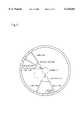
- FIG. 3shows a parallel mechanism of the present invention
- FIG. 4illustrates a state in which a spindle is at a tilting angle of 90° in the parallel mechanism of FIG. 3;
- FIG. 5is a plan view of a state in which the spindle is at a tilting angle of 90° while a tool turns round a workpiece, in the parallel mechanism of FIG. 3;
- FIG. 6is a perspective view of a six-axis multi-machining type machining center embodied by the parallel mechanism of the present invention.
- FIG. 7is a plan view of FIG. 6;
- FIG. 8is a cross-sectional view taken along the line A--A of FIG. 7;
- FIG. 9is a cross-sectional view taken along the line B--B of FIG. 8, that is a cross-section of an upward vertical guide;
- FIG. 10is a cross-sectional view taken along the line B--B of FIG. 8, that is a cross-section of a downward vertical guide;
- FIG. 11is a perspective view of a state in which a spindle is at a tilting angle of 90° in the six-axis multi-machining type machining center of FIG. 6;
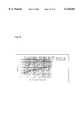
- FIG. 12depicts a Jacobian state in which a constraint equation is differentiated with respect to a passive joint variable when a tilting angle of the spindle changes from 0° to 90°, in the six-axis machining center shown FIGS. 6 to 11;
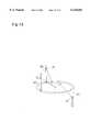
- FIG. 13shows passive joints where over-actuating actuators can be mounted
- FIG. 14depicts a Jacobian state in which a constraint equation is differentiated with respect to a passive joint variable when a tilting angle of the spindle changes from 0° to 90°, in a seven-axis machining center where over-actuating actuator is mounted at revolute joints of the downward vertical guide;
- FIG. 15shows that sensitivity of respective passive joints varies with a left singularity barrier (near 36° of incline of spindle) of FIG. 12;
- FIG. 16shows that sensitivity of respective passive joints varies with a right singularity barrier (near 55° of incline of spindle) of FIG. 12;
- FIG. 17is a perspective view of an eight-axis over-actuated machining center of the present invention.
- FIG. 18is a plan view of the eight-axis over-actuated machining center of FIG. 17;
- FIG. 19is a cross-section as taken along the line A--A of FIG. 18;
- FIG. 20in detail shows an upward rectilinear, vertical guide of the eight-axis over-actuated machining center of the present invention.
- FIG. 21in detail shows a downward rectilinear, vertical guide of the eight-axis over-actuated machining center of the present invention.
- a spindle 72is connected to three fixed length links 73, 74, and 75, that may be equal or different in length.
- the links 73, 74, and 75 shown in FIG. 3have the same lengths.
- These three fixed length links 73, 74, and 75move along three corresponding rectilinear, vertical guides 83, 84, and 85 in a vertical direction.
- a circular, horizontal guide 76allows the rectilinear, vertical guides 83, 84, and 85 to move horizontally on its circular arc.
- the spindle 72 and three fixed length links 73, 74, and 75are connected by spherical joints S.
- Revolute joints Rconnect the three fixed length links 73, 74, and 75 with the corresponding rectilinear, vertical guides 83, 84, and 85. They are connected to the rectilinear, vertical guides by prismatic joints P on a rectilinear line, in order to vertically move the fixed length links 73, 74, and 75 on the corresponding rectilinear, vertical guides 83, 84, and 85.
- Prismatic joints P' on a circular arcconnect the three rectilinear, vertical guides 83, 84, and 85 and circular, horizontal guide 76, for the purpose of horizontally moving these guides 83, 84, and 85 on the guide 76.
- the basic active joints of the parallel mechanismare the prismatic joints P on rectilinear line, for allowing the three fixed length links 73, 74, and 75 to move vertically on three rectilinear, vertical guides 83, 84, and 85, and prismatic joints P' on circular arc, for allowing the three rectilinear, vertical guides 83, 84, and 85 to move horizontally on circular, horizontal guide 76.
- These six jointsare driven to make the spindle capable of motion in six degrees of freedom.
- two 83 and 84 of three rectilinear, vertical guides 83, 84, and 85are located above the circular, horizontal guide 76, and the rest 85 is positioned under the guide 76.
- FIG. 4illustrates a state in which the spindle is at a tilting angle of 90° in the parallel mechanism of FIG. 3.
- the spindleis capable of motion at a tilting angle of 90°. It is hard to raise a tilting angle of the spindle up to 90° in a typical parallel mechanism. This is because there is a limit to a rotation angle of spherical joints for connecting the spindle and plural links.
- FIG. 5is a plan view of a state in which the spindle is at a tilting angle of 90° while a tool turns round a workpiece, in the parallel mechanism of FIG. 3. Even though the spindle at a tilting angle of 90° turns from a first position to a second position, three fixed length links maintain their relative positions, and three rectilinear, vertical guides move on circular, horizontal guide, so that there is no change in the angle of spherical joints S for connecting the spindle and three fixed length links.
- FIG. 6is a perspective view of a six-axis multi-machining type machining center embodied by the parallel mechanism of the present invention
- FIG. 7is a plan view of FIG. 6,
- FIG. 8is a cross-sectional view taken along the line A--A of FIG. 7.
- the multi-machining type machining centercomprises: a spindle system including a tool 1 and a spindle motor 2 for allowing rotation of the tool; and a movement system for determining a position and orientation of the tool.
- Three fixed length links 401, 402, and 403are connected to the spindle system by means of spherical joints 301, 302, and 303.
- the three fixed length links 401, 402, and 403are equal or different in length.
- the links 401, 402, and 403 shown in FIG. 6have the same lengths.
- the spherical joints 301, 302, and 303have the advantage of a relatively large, allowable angle of inclination more than 50°, in comparison to typical spherical joints with a tilting angle of 40°.
- Rectilinear, vertical guides 601, 602, and 603 and the three fixed length links 401, 402, and 403are connected by corresponding revolute joints 501, 502, and 503.
- Three fixed length links 401, 402, and 403 connected to the revolute joints 501, 502, and 503are driven by respective actuators for vertical movement 701, 702, and 703, to move vertically.
- the rectilinear, vertical guides 601, 602, and 603include two upward rectilinear, vertical guides 602 and 603 that are disposed above a circular, horizontal guide 8, a downward rectilinear, vertical guide 601 that is positioned under the guide 8.
- FIG. 9is a cross-sectional view taken along the line B--B of FIG. 8, that is a cross-section of an upward vertical guide
- FIG. 10is a cross-sectional view taken along the line B--B of FIG. 8, that is a cross-section of a downward vertical guide.
- the rectilinear, vertical guides 601, 602, and 603comprise: ball screws 621, 622, and 623 for allowing the respective, fixed length links 401, 402, and 403 to vertically move by the respective actuators for vertical movement 701, 702, and 703; ball nuts 611, 612, and 613 for connecting the ball screws 621, 622, and 623 to the revolute joints 501, 502, and 503 connected with the respective, fixed length links 401, 402, and 403; and couplings 631, 632, and 633 for connecting the ball screws 621, 622, and 623 to the respective actuators for vertical movement 701, 702, and 703.
- a rotational driving force of the actuators for vertical movement 701, 702, and 703are transmitted to the ball nuts 611, 612, and 613 through the ball screws 621, 622, and 623, before transmitted to the fixed length links 401, 402, and 403 through the revolute joints 501, 502, and 503 connected to the ball nuts 611, 612, and 613.
- the fixed length links 401, 402, and 403move along a vertical movement passage provided by the ball screws 621, 622, and 623.
- the rectilinear, vertical guides 601, 602, and 603are driven by respective actuators for horizontal movement 901, 902, and 903, to move horizontally on the circular, horizontal guide 8.
- a ring gear 81is provided outside the circular, horizontal guide 8
- pinion gears 821, 822, and 823 that are driven by the actuators for horizontal movement 901, 902, and 903,are provided at the rectilinear, vertical guides 601, 602, and 603.
- the pinion gears 821, 822, and 823 that are driven by the actuators for horizontal movement 901, 902, and 903,engage with the ring gear 81, so that the rectilinear, vertical guides 601, 602, and 603 perform their horizontal movements.
- Rollers 83are supplied to endure vertical load of the fixed length links 401, 402, and 403, a horizontal centrifugal force of the rectilinear, vertical guides 601, 602, and 603, and a horizontal or vertical internal force between robust bodies.
- the spindleis capable of motion in six degrees of freedom, to determine its position and orientation.
- the machining center with six actuators including three actuators for vertical movement and three actuators for horizontal movementis called six-axis machining center.
- the position and orientation of the tool for six-axis machining centerare determined by rotation of the actuators for vertical and horizontal movements.
- input values of respective movement actuators that are determined by mechanical interpretation,are controlled numerically, such that the relative position and orientation of the tool with respect to a workpiece are controlled to shape and form useful, desired products.
- the spindleis at a right angle with the workpiece, to perform a workpiece side machining by a single set-up.
- a rotation angle of spherical joints 301, 302, and 303 for connecting the fixed length links 401, 402, and 403 to the spindle systemis the decisive element in determining the position and orientation of the tool.
- the range of vertical movement of the fixed length links 401, 402, and 403 on the rectilinear, vertical guides 601, 602, and 603,is set up, not to apply a burden to the spherical joints 301, 302, and 303.
- a limit switch for fixed length link vertical movement limit 11is formed at each of the rectilinear, vertical guides 601, 602, and 603.
- Three rectilinear, vertical guides 601, 602, and 603have their respective collision prevention limit switches 10 and 10' for preventing them from colliding with one another when they are driven by the respective actuators for horizontal movement 901, 902, and 903, to move horizontally on the circular, horizontal guide 8.
- the present inventionis constructed of a horizontal movement recovery limit switch 12 and a vertical movement recovery limit switch 13.
- the six-axis multi-machining type machining centerfurther includes a workpiece rotation system for turning a workpiece itself, in addition to the spindle system and movement system.
- the workpiece rotation systemcomprises: a fixing member 31 for fixing a workpiece 20; a chuck 32 for supporting the fixing member 31; an air compression cylinder 35 connected to the chuck 32; a pulley 33 for rotating the chuck 32; and a pulley driving motor 36 for operating the pulley 33. If the pulley driving motor 36 isn't a direct-coupled motor, a V-belt 34 is further included to transmit a rotational driving force of the pulley driving motor 36 to the pulley 33.
- the workpiece rotation systemallows a vertical turning process, with the spindle at a right angle with the workpiece.
- the parallel mechanism of the present inventionmay have the problem of actuator's singularity, that will be discussed hereinbelow.
- uis indicative of a driving joint
- vis indicative of a passive joint
- FIG. 12depicts a Jacobian state in which a constraint equation is differentiated with respect to a passive joint variable when a tilting angle of the spindle changes from 0° to 90°, in the six-axis machining center shown FIGS. 6 to 11.
- a horizontal shaftis indicative of an angle of inclination of a spindle
- a vertical shaftis indicative of a rotation angle ⁇ of a spindle itself.
- a light part of FIG. 12means that the spindle slopes smoothly, and a dark part of FIG. 12 means that there is an actuator's singularity, not to drive all the driving joints independently.
- the present inventionprovides an over-actuated machining center having an additional actuator for over-actuating passive joints, in addition to six actuators for actuating six driving joints.
- the additional actuatoris at least more than one actuator.
- a seven-axis machining center provided with an over-actuating actuatorwill now be described hereinbelow as a first embodiment of the present invention.
- FIG. 13shows passive joints where over-actuating actuators can be mounted.
- Revolute joints 51, 52, and 53 of rectilinear, vertical guides 331, 332, and 333 of six-axis machining centerare passive joints.
- the seven-axis machining centerhas a construction which mounts an over-actuating actuator at any one of the revolute joints 51, 52, and 53, to actuate them.
- the over-actuating actuatoris preferably mounted at the revolute joint 51 of the downward rectilinear, vertical guide 331.
- FIG. 14depicts a Jacobian state in which a constraint equation is differentiated with respect to a passive joint variable when a tilting angle of the spindle changes from 0° to 90°, in the seven-axis machining center where over-actuating actuators are mounted at revolute joints of the downward vertical guides.
- a horizontal shaftis indicative of an angle of inclination of a spindle
- a vertical shaftis indicative of a rotation angle ⁇ of a spindle itself.
- a singularity barrierdisappears, and instead the singularity exists in the form of a point. And the singularity isn't a barrier near 36° of incline of spindle, but still exists badly.
- An eight-axis machining center with two over-actuating actuatorsis presented by the present invention.
- a sensitivity test to the revolute joints 51, 52, and 53, shown in FIG. 13is performed to select a passive joint for adding an over-actuating actuator.
- the revolute joint 51 of downward rectilinear, vertical guide 331is referred to as a first passive joint
- the revolute joint 52 of upward rectilinear, vertical guide 332as a second passive joint
- the revolute joint 53 of another upward rectilinear, vertical guide 333as a third passive joint.
- FIG. 15shows that sensitivity of respective passive joints varies with a left singularity barrier (near 36° of incline of spindle) of FIG. 12.
- FIG. 16shows that sensitivity of respective passive joints varies with a right singularity barrier (near 55° of incline of spindle) of FIG. 12.
- first passive joint 51is still smaller than that of other passive joints 52 and 53 with respect to left singularity barrier, but gets larger with increasing rotation angle of spindle.
- second and third passive joints 52 and 53is smaller than that of first passive joint 51 with respect to right singularity barrier.
- the seven-axis machining center having one over-actuating actuator mounted at first passive joint 51can't completely solve the problem of actuator's singularity near 37° of incline of spindle.
- a first over-actuated actuatoris mounted at the first passive joint 51 that is a revolute joint of a downward rectilinear, vertical guide, and a second over-actuating actuator at either of the second and third passive joints 52 and 53 that are revolute joints of upward rectilinear, vertical guides.
- the actuator's singularityis removed by the eight-axis over-actuated machining center of the present invention, and the spindle inclines smoothly with angles of 0° to 90°.
- FIG. 17is a perspective view of the eight-axis over-actuated machining center of the present invention.
- FIG. 18is a plan view of the eight-axis over-actuated machining center of FIG. 17.
- FIG. 19is a cross-section as taken along the line A--A of FIG. 18.
- FIG. 20in detail shows an upward rectilinear, vertical guide of the eight-axis over-actuated machining center of the present invention.
- FIG. 21in detail shows a downward rectilinear, vertical guide of the eight-axis over-actuated machining center of the present invention.
- the eight-axis over-actuated machining centerhas the same construction as a general machining center. That is, the eight-axis over-actuated machining center comprises: a spindle system having a tool and a spindle motor 38 for allowing rotation of the tool; a movement system for determining a position and orientation of the tool; and a workpiece rotation system for turning a workpiece.
- the movement systemhas eight actuators including three actuators for vertical movement 111, 112, and 113, and three actuators for horizontal movement 121, 122, and 123 plus two over-actuating actuators 130 and 131.
- the three actuators for vertical movement 111, 112, and 113allow fixed length links 351, 352, and 353 to move on the rectilinear, vertical guides.
- a rotational driving force of three actuators for vertical movement 111, 112, and 113are transmitted to ball nuts 91 through respective ball screws 92, before transmitted to the fixed length links 351, 352, and 353 through revolute joints 361, 362, and 363 connected to the ball nuts 91.
- the fixed length links 351, 352, and 353move along a vertical movement passage provided by the ball screws 92.
- the respective rectilinear, vertical guidesmove along a circumference passage provided by a circular, horizontal guide 31 by means of three actuators for horizontal movement 121, 122, and 123.
- the revolute joint of downward rectilinear, vertical guide 331is over-actuated by first over-actuating actuator 130, and the revolute joint of upward rectilinear, vertical guide 332 is over-actuating by second over-actuated actuator 131.
- Two additional over-actuating actuators 130 and 131remove the problem of actuator's singularity completely, and there is no shaking when an angle of inclination of spindle is changed from 0° to 90°.
- a nine-axis over-actuated machining centerprovided by the present invention, has a construction that mounts over-actuating actuators at all of revolute joints of three rectilinear, vertical guides. A position and orientation of a tool are controlled by nine actuators of the nine-axis machining center.
- the over-actuated machining center of the present inventionsolves the problem of actuator's singularity that may be included in the parallel mechanism. Also, a turning process is possible with a tilting angle 90° of the spindle.
Landscapes
- Engineering & Computer Science (AREA)
- Mechanical Engineering (AREA)
- Machine Tool Units (AREA)
Abstract
Description
g(u,v)=0, uεR.sup.n, vεR.sup.m, g:R.sup.n ×R.sup.m →R.sup.m,
Claims (43)
Applications Claiming Priority (4)
| Application Number | Priority Date | Filing Date | Title |
|---|---|---|---|
| KR1019970058254AKR100237553B1 (en) | 1997-11-05 | 1997-11-05 | Parallel mechanism structure for controlling of 3-dimensional position and orientation |
| KR97-58254 | 1997-11-05 | ||
| KR97-59556 | 1997-11-12 | ||
| KR1019970059556AKR100241701B1 (en) | 1997-11-12 | 1997-11-12 | Complex Process Type Machining Center |
Publications (1)
| Publication Number | Publication Date |
|---|---|
| US6135683Atrue US6135683A (en) | 2000-10-24 |
Family
ID=26633163
Family Applications (1)
| Application Number | Title | Priority Date | Filing Date |
|---|---|---|---|
| US09/183,194Expired - LifetimeUS6135683A (en) | 1997-11-05 | 1998-10-30 | Parallel mechanism for multi-machining type machining center |
Country Status (1)
| Country | Link |
|---|---|
| US (1) | US6135683A (en) |
Cited By (44)
| Publication number | Priority date | Publication date | Assignee | Title |
|---|---|---|---|---|
| US6431802B1 (en)* | 1998-11-03 | 2002-08-13 | Ds Technologie Werkzeugmaschinenbau Gmbh | Articulated tool head |
| US6503033B1 (en)* | 2000-06-21 | 2003-01-07 | Jongwon Kim | Parallel mechanism structure for controlling three-dimensional position and orientation |
| US6557235B1 (en) | 2002-03-06 | 2003-05-06 | The Regents Of The University Of Michigan | Bi-axial coplanar apparatus |
| US20060104734A1 (en)* | 2004-11-12 | 2006-05-18 | Mathis Dennis R | Self-normalizing contour drilling machine |
| US20080193241A1 (en)* | 2006-04-30 | 2008-08-14 | Tianjin University | Parallel Mechanism Having Two Rotational and One Translational Degrees of Freedom |
| US20090143907A1 (en)* | 2004-09-24 | 2009-06-04 | Michel Demathelin | Robotic Positioning and Orientation Device and Needle Holder Comprising One Such Device |
| CN101301753B (en)* | 2008-05-27 | 2010-06-02 | 中国科学院国家天文台南京天文光学技术研究所 | Swing arm six degrees of freedom mechanism |
| CN102211219A (en)* | 2011-06-02 | 2011-10-12 | 江西电力职业技术学院 | Electromechanical integrated six-degree-of-freedom teaching machine tool |
| CN102294500A (en)* | 2010-06-25 | 2011-12-28 | 呼和浩特铁路局焊轨段 | Triaxial steel rail drill press adjustable in center distance and centre height of main shaft |
| CN102554914A (en)* | 2012-01-06 | 2012-07-11 | 上海大学 | Novel three-degrees-of-freedom under-actuated mechanism |
| CN102601619A (en)* | 2011-12-20 | 2012-07-25 | 山东遨游汽车制动系统股份有限公司 | Pump and cylinder drilling device |
| CN102615642A (en)* | 2012-03-27 | 2012-08-01 | 天津大学 | Parallel manipulator capable of realizing five-coordinate machining capacity |
| CN102626870A (en)* | 2012-05-03 | 2012-08-08 | 清华大学 | Three-DOF (Degree of Freedom) parallel spindle head with single-DOF hinge |
| CN102990654A (en)* | 2012-12-27 | 2013-03-27 | 广西大学 | Parallel mechanism containing two pprrr closed-loop sub-chains |
| CN103100938A (en)* | 2012-11-04 | 2013-05-15 | 宁波瑞铭机械有限公司 | Upper shaft drilling boring milling flat machine tool |
| CN103158157A (en)* | 2013-04-01 | 2013-06-19 | 天津工业大学 | Simulated joint mechanism with radial direction buffering function |
| CN103192280A (en)* | 2013-03-14 | 2013-07-10 | 瑞立集团瑞安汽车零部件有限公司 | Rotary jig for multi-drill machine to synchronously process multiple procedures |
| CN103737249A (en)* | 2013-12-30 | 2014-04-23 | 姚晓明 | Method for processing spherical member and ball socket on end mill |
| US20140311271A1 (en)* | 2013-04-23 | 2014-10-23 | Northwestern University | Translational parallel manipulators and methods of operating the same |
| CN104210301A (en)* | 2013-05-31 | 2014-12-17 | 曹欣 | Automatic levelling multifunctional caving machine |
| CN104308833A (en)* | 2014-10-24 | 2015-01-28 | 天津大学 | Decoupling type two-freedom-degree rotation parallel mechanism capable of achieving hemisphere rotation |
| CN104493825A (en)* | 2014-10-29 | 2015-04-08 | 北京理工大学 | Cooperating device for micro-nano operating robot and operating method for microinjection |
| CN105215979A (en)* | 2015-11-03 | 2016-01-06 | 河南理工大学 | A kind of 3-freedom parallel mechanism |
| CN105773314A (en)* | 2016-04-28 | 2016-07-20 | 奉化市欧特瑞智能科技有限公司 | Full-automatic multi-procedure synchronous machining composite numerical control machine tool |
| CN105817889A (en)* | 2016-04-28 | 2016-08-03 | 奉化市欧特瑞智能科技有限公司 | Full-automatic high-precision compound numerical control machine tool |
| CN105856204A (en)* | 2016-06-07 | 2016-08-17 | 浙江理工大学 | Holohedral symmetry parallel robot for machining complex curved surface |
| CN105978242A (en)* | 2016-06-16 | 2016-09-28 | 吴胜强 | Automatic flow device and technological process for machining servo motors |
| CN105992689A (en)* | 2015-01-19 | 2016-10-05 | 崇实大学校产学协力团 | 3d printer having dual stage structure |
| CN106078682A (en)* | 2016-06-28 | 2016-11-09 | 徐香庭 | A kind of parallel connection type high ferro dedicated track intelligence polisher mechanical arm |
| CN106078674A (en)* | 2016-03-25 | 2016-11-09 | 合肥工业大学 | A kind of modularity flexible cable parallel mechanism experiment porch and via Self-reconfiguration Method thereof |
| CN106112971A (en)* | 2016-07-14 | 2016-11-16 | 南京林业大学 | A kind of pedestal position of articulating point self-adjustable six degree of freedom incidence flexible exoskeleton system |
| CN106862668A (en)* | 2017-02-28 | 2017-06-20 | 东北大学 | A kind of two ultrasonic vibration auxiliary cutting off machine in parallel |
| CN106926219A (en)* | 2016-12-31 | 2017-07-07 | 重庆大学 | The Three Degree Of Freedom device of the adjustable three side chains parallel drive of rigidity |
| CN106945071A (en)* | 2017-03-22 | 2017-07-14 | 陕西科技大学 | A kind of Three Degree Of Freedom lumbar device of anthropomorphic robot |
| CN107717499A (en)* | 2017-11-07 | 2018-02-23 | 广西大学 | A kind of six degree of freedom via Self-reconfiguration becomes cell type parallel machine |
| WO2018223363A1 (en)* | 2017-06-09 | 2018-12-13 | 深圳先进技术研究院 | Three-degrees-of-freedom decoupled spherical parallel mechanism |
| CN109333547A (en)* | 2018-10-16 | 2019-02-15 | 中国矿业大学 | A kind of multi-parallel co-integration large surface parts processing equipment and processing method |
| CN110450028A (en)* | 2019-09-18 | 2019-11-15 | 浙江大学宁波理工学院 | A kind of complex-curved grinding and polishing device |
| CN111251012A (en)* | 2020-03-02 | 2020-06-09 | 周云飞 | Full-automatic high-efficient drilling equipment of carousel formula car bearing cap |
| CN111451831A (en)* | 2020-03-30 | 2020-07-28 | 遵义宏港机械有限公司 | Machining flow transfer line |
| US11269143B2 (en)* | 2016-09-30 | 2022-03-08 | 3Sae Technologies, Inc. | Multi-axis positioner |
| CN114603329A (en)* | 2022-03-15 | 2022-06-10 | 上海智能制造功能平台有限公司 | 3PRS-3RRR dual-platform equipment for intelligent assembly |
| US20220281169A1 (en)* | 2019-08-20 | 2022-09-08 | Kumovis GmbH | Positioning system for an additive manufacturing system, and additive manufacturing system |
| US11681100B2 (en) | 2016-09-30 | 2023-06-20 | 3Sae Technologies, Inc. | Multi-axis positioner |
Citations (8)
| Publication number | Priority date | Publication date | Assignee | Title |
|---|---|---|---|---|
| US2823591A (en)* | 1953-11-13 | 1958-02-18 | Kaiser Metal Products Inc | Tool adjustment |
| US5267818A (en)* | 1991-08-05 | 1993-12-07 | Optima Industries, Inc. | Arrangement for providing planar movement of a machine tool |
| US5401128A (en)* | 1991-08-26 | 1995-03-28 | Ingersoll Milling Machine Company | Octahedral machine with a hexapodal triangular servostrut section |
| US5466085A (en)* | 1989-09-01 | 1995-11-14 | Giddings & Lewis, Inc. | Gimbal assembly for six axis machine tool |
| US5575597A (en)* | 1991-04-05 | 1996-11-19 | Geodetic Technology International Holdings N.V. | Mechanical manipulator |
| US5715729A (en)* | 1994-11-29 | 1998-02-10 | Toyoda Koki Kabushiki Kaisha | Machine tool having parallel structure |
| US5941128A (en)* | 1996-10-21 | 1999-08-24 | Toyoda Kokoi Kabushiki Kaisha | Machine tool having parallel structure |
| US5960672A (en)* | 1996-03-21 | 1999-10-05 | Vdw Verein Deutscher Werkzeugmaschinenfabriken E.V. | Device for generating a defined position and orientation of at least one platform |
- 1998
- 1998-10-30USUS09/183,194patent/US6135683A/ennot_activeExpired - Lifetime
Patent Citations (8)
| Publication number | Priority date | Publication date | Assignee | Title |
|---|---|---|---|---|
| US2823591A (en)* | 1953-11-13 | 1958-02-18 | Kaiser Metal Products Inc | Tool adjustment |
| US5466085A (en)* | 1989-09-01 | 1995-11-14 | Giddings & Lewis, Inc. | Gimbal assembly for six axis machine tool |
| US5575597A (en)* | 1991-04-05 | 1996-11-19 | Geodetic Technology International Holdings N.V. | Mechanical manipulator |
| US5267818A (en)* | 1991-08-05 | 1993-12-07 | Optima Industries, Inc. | Arrangement for providing planar movement of a machine tool |
| US5401128A (en)* | 1991-08-26 | 1995-03-28 | Ingersoll Milling Machine Company | Octahedral machine with a hexapodal triangular servostrut section |
| US5715729A (en)* | 1994-11-29 | 1998-02-10 | Toyoda Koki Kabushiki Kaisha | Machine tool having parallel structure |
| US5960672A (en)* | 1996-03-21 | 1999-10-05 | Vdw Verein Deutscher Werkzeugmaschinenfabriken E.V. | Device for generating a defined position and orientation of at least one platform |
| US5941128A (en)* | 1996-10-21 | 1999-08-24 | Toyoda Kokoi Kabushiki Kaisha | Machine tool having parallel structure |
Cited By (72)
| Publication number | Priority date | Publication date | Assignee | Title |
|---|---|---|---|---|
| US6431802B1 (en)* | 1998-11-03 | 2002-08-13 | Ds Technologie Werkzeugmaschinenbau Gmbh | Articulated tool head |
| US6503033B1 (en)* | 2000-06-21 | 2003-01-07 | Jongwon Kim | Parallel mechanism structure for controlling three-dimensional position and orientation |
| US6557235B1 (en) | 2002-03-06 | 2003-05-06 | The Regents Of The University Of Michigan | Bi-axial coplanar apparatus |
| US7881823B2 (en)* | 2004-09-24 | 2011-02-01 | Institut National Des Sciences Appliquees | Robotic positioning and orientation device and needle holder comprising one such device |
| US20090143907A1 (en)* | 2004-09-24 | 2009-06-04 | Michel Demathelin | Robotic Positioning and Orientation Device and Needle Holder Comprising One Such Device |
| US20060104734A1 (en)* | 2004-11-12 | 2006-05-18 | Mathis Dennis R | Self-normalizing contour drilling machine |
| US20080193241A1 (en)* | 2006-04-30 | 2008-08-14 | Tianjin University | Parallel Mechanism Having Two Rotational and One Translational Degrees of Freedom |
| US7793564B2 (en)* | 2006-04-30 | 2010-09-14 | Tianjin University | Parallel mechanism having two rotational and one translational degrees of freedom |
| CN101301753B (en)* | 2008-05-27 | 2010-06-02 | 中国科学院国家天文台南京天文光学技术研究所 | Swing arm six degrees of freedom mechanism |
| CN102294500A (en)* | 2010-06-25 | 2011-12-28 | 呼和浩特铁路局焊轨段 | Triaxial steel rail drill press adjustable in center distance and centre height of main shaft |
| CN102294500B (en)* | 2010-06-25 | 2014-03-12 | 呼和浩特铁路局焊轨段 | Triaxial steel rail drill press adjustable in center distance and centre height of main shaft |
| CN102211219A (en)* | 2011-06-02 | 2011-10-12 | 江西电力职业技术学院 | Electromechanical integrated six-degree-of-freedom teaching machine tool |
| CN102211219B (en)* | 2011-06-02 | 2015-04-01 | 国家电网公司 | Electromechanical integrated six-degree-of-freedom teaching machine tool |
| CN102601619A (en)* | 2011-12-20 | 2012-07-25 | 山东遨游汽车制动系统股份有限公司 | Pump and cylinder drilling device |
| CN102554914A (en)* | 2012-01-06 | 2012-07-11 | 上海大学 | Novel three-degrees-of-freedom under-actuated mechanism |
| CN102615642B (en)* | 2012-03-27 | 2014-04-30 | 天津大学 | Parallel manipulator capable of realizing five-coordinate machining capacity |
| CN102615642A (en)* | 2012-03-27 | 2012-08-01 | 天津大学 | Parallel manipulator capable of realizing five-coordinate machining capacity |
| CN102626870A (en)* | 2012-05-03 | 2012-08-08 | 清华大学 | Three-DOF (Degree of Freedom) parallel spindle head with single-DOF hinge |
| CN102626870B (en)* | 2012-05-03 | 2013-12-11 | 清华大学 | Three-DOF (Degree of Freedom) parallel spindle head with single-DOF hinge |
| CN103100938B (en)* | 2012-11-04 | 2015-11-25 | 宁波瑞铭机械有限公司 | Upper axle boring bore hole milling flat lathe |
| CN103100938A (en)* | 2012-11-04 | 2013-05-15 | 宁波瑞铭机械有限公司 | Upper shaft drilling boring milling flat machine tool |
| CN102990654A (en)* | 2012-12-27 | 2013-03-27 | 广西大学 | Parallel mechanism containing two pprrr closed-loop sub-chains |
| CN102990654B (en)* | 2012-12-27 | 2015-08-26 | 广西大学 | A kind of parallel institution containing two pprrr closed-loop subchain |
| CN103192280A (en)* | 2013-03-14 | 2013-07-10 | 瑞立集团瑞安汽车零部件有限公司 | Rotary jig for multi-drill machine to synchronously process multiple procedures |
| CN103192280B (en)* | 2013-03-14 | 2015-10-28 | 瑞立集团瑞安汽车零部件有限公司 | The rotary jig of multi spindle drilling machine synchronous processing multiple operation |
| CN103158157A (en)* | 2013-04-01 | 2013-06-19 | 天津工业大学 | Simulated joint mechanism with radial direction buffering function |
| US20140311271A1 (en)* | 2013-04-23 | 2014-10-23 | Northwestern University | Translational parallel manipulators and methods of operating the same |
| US9283671B2 (en)* | 2013-04-23 | 2016-03-15 | Northwestern University | Translational parallel manipulators and methods of operating the same |
| US10583552B2 (en) | 2013-04-23 | 2020-03-10 | Northwestern University | Translational parallel manipulators and methods of operating the same |
| CN104210301A (en)* | 2013-05-31 | 2014-12-17 | 曹欣 | Automatic levelling multifunctional caving machine |
| CN103737249A (en)* | 2013-12-30 | 2014-04-23 | 姚晓明 | Method for processing spherical member and ball socket on end mill |
| CN104308833A (en)* | 2014-10-24 | 2015-01-28 | 天津大学 | Decoupling type two-freedom-degree rotation parallel mechanism capable of achieving hemisphere rotation |
| CN104308833B (en)* | 2014-10-24 | 2016-01-20 | 天津大学 | Decoupling type two one-rotation parallel mechanism that hemisphere rotates can be realized |
| CN104493825A (en)* | 2014-10-29 | 2015-04-08 | 北京理工大学 | Cooperating device for micro-nano operating robot and operating method for microinjection |
| CN105992689A (en)* | 2015-01-19 | 2016-10-05 | 崇实大学校产学协力团 | 3d printer having dual stage structure |
| US10118340B2 (en)* | 2015-01-19 | 2018-11-06 | Foundation Of Soongsil University-Industry Cooperation | 3D printer having dual stage structure |
| US10543642B2 (en) | 2015-01-19 | 2020-01-28 | Foundation Of Soongsil University-Industry Cooperation | 3D printer having dual stage structure |
| US10543641B2 (en) | 2015-01-19 | 2020-01-28 | Foundation Of Soongsil University-Industry Cooperation | 3D printer having dual stage structure |
| CN105215979A (en)* | 2015-11-03 | 2016-01-06 | 河南理工大学 | A kind of 3-freedom parallel mechanism |
| CN105215979B (en)* | 2015-11-03 | 2017-03-01 | 河南理工大学 | A kind of 3-freedom parallel mechanism |
| CN106078674B (en)* | 2016-03-25 | 2020-12-15 | 合肥工业大学 | A modular flexible-cable parallel mechanism experimental platform and its self-reconfiguration method |
| CN106078674A (en)* | 2016-03-25 | 2016-11-09 | 合肥工业大学 | A kind of modularity flexible cable parallel mechanism experiment porch and via Self-reconfiguration Method thereof |
| CN105817889A (en)* | 2016-04-28 | 2016-08-03 | 奉化市欧特瑞智能科技有限公司 | Full-automatic high-precision compound numerical control machine tool |
| CN105773314A (en)* | 2016-04-28 | 2016-07-20 | 奉化市欧特瑞智能科技有限公司 | Full-automatic multi-procedure synchronous machining composite numerical control machine tool |
| CN105773314B (en)* | 2016-04-28 | 2018-03-16 | 奉化市欧特瑞智能科技有限公司 | A kind of full-automatic multiple operation synchronous processing combined numerically controlled machine |
| CN105817889B (en)* | 2016-04-28 | 2018-03-20 | 奉化市欧特瑞智能科技有限公司 | A kind of full-automatic high precision combined numerically controlled machine |
| CN105856204A (en)* | 2016-06-07 | 2016-08-17 | 浙江理工大学 | Holohedral symmetry parallel robot for machining complex curved surface |
| CN105978242A (en)* | 2016-06-16 | 2016-09-28 | 吴胜强 | Automatic flow device and technological process for machining servo motors |
| CN106078682B (en)* | 2016-06-28 | 2018-05-11 | 汪培杰 | A kind of parallel connection type high ferro dedicated track intelligence grinding machine arm |
| CN106078682A (en)* | 2016-06-28 | 2016-11-09 | 徐香庭 | A kind of parallel connection type high ferro dedicated track intelligence polisher mechanical arm |
| CN106112971A (en)* | 2016-07-14 | 2016-11-16 | 南京林业大学 | A kind of pedestal position of articulating point self-adjustable six degree of freedom incidence flexible exoskeleton system |
| US11269143B2 (en)* | 2016-09-30 | 2022-03-08 | 3Sae Technologies, Inc. | Multi-axis positioner |
| US12287513B2 (en) | 2016-09-30 | 2025-04-29 | 3Sae Technologies, Inc. | Multi-axis positioner |
| US20250028117A1 (en)* | 2016-09-30 | 2025-01-23 | 3Sae Technologies, Inc. | Multi-axis positioner |
| US11681100B2 (en) | 2016-09-30 | 2023-06-20 | 3Sae Technologies, Inc. | Multi-axis positioner |
| US11971578B2 (en) | 2016-09-30 | 2024-04-30 | 3Sae Technologies, Inc. | Multi-axis positioner |
| CN106926219A (en)* | 2016-12-31 | 2017-07-07 | 重庆大学 | The Three Degree Of Freedom device of the adjustable three side chains parallel drive of rigidity |
| CN106862668A (en)* | 2017-02-28 | 2017-06-20 | 东北大学 | A kind of two ultrasonic vibration auxiliary cutting off machine in parallel |
| CN106945071B (en)* | 2017-03-22 | 2019-04-26 | 陕西科技大学 | A three-degree-of-freedom waist device for a humanoid robot |
| CN106945071A (en)* | 2017-03-22 | 2017-07-14 | 陕西科技大学 | A kind of Three Degree Of Freedom lumbar device of anthropomorphic robot |
| US11331791B2 (en) | 2017-06-09 | 2022-05-17 | Shenzhen Institute Of Advanced Technology | 3 degree-of-freedoms decoupling spherical parallel mechanism |
| WO2018223363A1 (en)* | 2017-06-09 | 2018-12-13 | 深圳先进技术研究院 | Three-degrees-of-freedom decoupled spherical parallel mechanism |
| CN107717499A (en)* | 2017-11-07 | 2018-02-23 | 广西大学 | A kind of six degree of freedom via Self-reconfiguration becomes cell type parallel machine |
| CN109333547B (en)* | 2018-10-16 | 2021-02-12 | 中国矿业大学 | Multi-parallel co-fused large-curved-surface part machining equipment and machining method |
| CN109333547A (en)* | 2018-10-16 | 2019-02-15 | 中国矿业大学 | A kind of multi-parallel co-integration large surface parts processing equipment and processing method |
| US20220281169A1 (en)* | 2019-08-20 | 2022-09-08 | Kumovis GmbH | Positioning system for an additive manufacturing system, and additive manufacturing system |
| CN110450028B (en)* | 2019-09-18 | 2020-12-22 | 浙江大学宁波理工学院 | Complex curved surface grinding and polishing device |
| CN110450028A (en)* | 2019-09-18 | 2019-11-15 | 浙江大学宁波理工学院 | A kind of complex-curved grinding and polishing device |
| CN111251012A (en)* | 2020-03-02 | 2020-06-09 | 周云飞 | Full-automatic high-efficient drilling equipment of carousel formula car bearing cap |
| CN111451831B (en)* | 2020-03-30 | 2022-02-15 | 遵义宏港机械有限公司 | Machining flow transfer line |
| CN111451831A (en)* | 2020-03-30 | 2020-07-28 | 遵义宏港机械有限公司 | Machining flow transfer line |
| CN114603329A (en)* | 2022-03-15 | 2022-06-10 | 上海智能制造功能平台有限公司 | 3PRS-3RRR dual-platform equipment for intelligent assembly |
Similar Documents
| Publication | Publication Date | Title |
|---|---|---|
| US6135683A (en) | Parallel mechanism for multi-machining type machining center | |
| US5533418A (en) | Spherical robotic shoulder joint | |
| EP1863734B1 (en) | Parallel robot | |
| US5673595A (en) | Four degree-of-freedom manipulator | |
| US7127962B2 (en) | Four-degree-of-freedom parallel manipulator for producing Schönflies motions | |
| EP0279591A1 (en) | Robotic Manipulator | |
| EP1982801A1 (en) | Parallel-link operational device | |
| EP1365893B1 (en) | Industrial robot | |
| JP2010184328A (en) | Parallel link robot provided with attitude changing mechanism having 3-freedom | |
| WO2005063453A1 (en) | Parallel kinematic manipulator for large workspace | |
| WO2009148603A1 (en) | Robotic manipulator | |
| US5698959A (en) | Robot with two dimensional driving mechanism | |
| CA2452804A1 (en) | Device for the displacement and/or positioning of an object in five axes | |
| CN1138194C (en) | Parallel mechanism for controlling three-dimensional position and orientation | |
| JP5394358B2 (en) | Parallel link robot with posture change mechanism with 3 degrees of freedom | |
| JP2569277B2 (en) | Drive with three degrees of freedom in space | |
| JP3002459B2 (en) | Multi-step machining center and its parallel mechanism structure | |
| KR101021172B1 (en) | Hanging parallel mechanism structure | |
| WO2004056538A1 (en) | A parallel kinematic manipulator and a method of operating the same, including pairwise actuators | |
| Budde et al. | Workspace enlargement of a triglide robot by changing working and assembly mode | |
| JPH0760678A (en) | Parallel link manipulator | |
| JP2009045739A (en) | Parallel link type working device | |
| JPH091491A (en) | Robot hand mechanism | |
| KR100237552B1 (en) | Parallel mechanism structure for controlling of 3-dimensional position and orientation | |
| WO2022107652A1 (en) | Work device |
Legal Events
| Date | Code | Title | Description |
|---|---|---|---|
| AS | Assignment | Owner name:PARK, CHONGWOO, KOREA, REPUBLIC OF Free format text:ASSIGNMENT OF ASSIGNORS INTEREST;ASSIGNORS:KIM, JONGWON;PARK, CHONGWOO;BAE, WOK-KWAN;AND OTHERS;REEL/FRAME:009560/0338;SIGNING DATES FROM 19981023 TO 19981026 Owner name:KIM, JONGWON, KOREA, REPUBLIC OF Free format text:ASSIGNMENT OF ASSIGNORS INTEREST;ASSIGNORS:KIM, JONGWON;PARK, CHONGWOO;BAE, WOK-KWAN;AND OTHERS;REEL/FRAME:009560/0338;SIGNING DATES FROM 19981023 TO 19981026 | |
| STCF | Information on status: patent grant | Free format text:PATENTED CASE | |
| FPAY | Fee payment | Year of fee payment:4 | |
| AS | Assignment | Owner name:SEOUL NATIONAL UNIVERSITY INDUSTRY FOUNDATION, KOR Free format text:ASSIGNMENT OF ASSIGNORS INTEREST;ASSIGNORS:KIM, JONGWON;PARK, CHONGWOO;REEL/FRAME:020143/0140;SIGNING DATES FROM 20071015 TO 20071018 | |
| FPAY | Fee payment | Year of fee payment:8 | |
| FPAY | Fee payment | Year of fee payment:12 | |
| FEPP | Fee payment procedure | Free format text:PAYER NUMBER DE-ASSIGNED (ORIGINAL EVENT CODE: RMPN); ENTITY STATUS OF PATENT OWNER: SMALL ENTITY Free format text:PAYOR NUMBER ASSIGNED (ORIGINAL EVENT CODE: ASPN); ENTITY STATUS OF PATENT OWNER: SMALL ENTITY |