US6135647A - System and method for representing a system level RTL design using HDL independent objects and translation to synthesizable RTL code - Google Patents
System and method for representing a system level RTL design using HDL independent objects and translation to synthesizable RTL codeDownload PDFInfo
- Publication number
- US6135647A US6135647AUS08/956,874US95687497AUS6135647AUS 6135647 AUS6135647 AUS 6135647AUS 95687497 AUS95687497 AUS 95687497AUS 6135647 AUS6135647 AUS 6135647A
- Authority
- US
- United States
- Prior art keywords
- hdl
- code
- representation
- module
- rtl
- Prior art date
- Legal status (The legal status is an assumption and is not a legal conclusion. Google has not performed a legal analysis and makes no representation as to the accuracy of the status listed.)
- Expired - Lifetime
Links
Images


Classifications
- G—PHYSICS
- G06—COMPUTING OR CALCULATING; COUNTING
- G06F—ELECTRIC DIGITAL DATA PROCESSING
- G06F30/00—Computer-aided design [CAD]
- G06F30/30—Circuit design
Definitions
- the inventionrelates generally to the field of electronic design automation systems, more particularly to representing system level register transfer level (“RTL”) hardware designs and translating the design into synthesizable RTL code.
- RTLsystem level register transfer level
- HDLregister transfer level
- HDLsprovide a rich set of constructs to describe the functionality of a module at RTL.
- the functionalityis described by using high level constructs such as concurrent PROCESS blocks with sensitization lists, IF statements, CASE statements, and assignment statements that use logical operators, arithmetic operators, and relational operators.
- Verilog and VHDLare the most popular HDLs among designers and both are IEEE standards.
- the present inventioncomprises a system and method for representing a system level RTL hardware design using an HDL independent RTL representation and translation into synthesizable RTL code.
- the present inventioncreates an object-oriented library which can be used to implement RTL hardware designs in terms of HDL independent objects. Instead of implementing multiple HDL instances of hardware modules, the invention enables software tool programmers to implement one HDL-independent instance of the hardware module. As a result, a programmer can focus his efforts on generating the functionality of the module and can be relieved from the time consuming task of generating the detailed syntax of multiple HDLs.
- the present inventionalso maintains synchronization across multiple HDLs so that a software designer can generate HDL code for any supported HDL, e.g., Verilog or VHDL, thus making software maintenance easier.
- FIG. 1is an illustration of a computer in which the preferred embodiment of the code generation part of the invention operates.
- FIG. 2is a more detailed illustration of a computer environment in which the preferred embodiment of the code generation part of the invention resides.
- FIG. 3is a more detailed illustration of the HDL independent objected oriented RTL code generation library according to the preferred embodiment of the present invention.
- FIG. 4is a more detailed illustration of the module class according to the preferred embodiment of the present invention.
- FIG. 5is a more detailed illustration of the block class according to the preferred embodiment of the present invention.
- FIG. 6is a more detailed illustration of the statement class according to the preferred embodiment of the present invention.
- FIG. 7is a more detailed illustration of the expression class according to the preferred embodiment of the present invention.
- FIG. 8is a more detailed illustration of the port class according to the preferred embodiment of the present invention.
- FIG. 9is a more detailed illustration of the signal class according to the preferred embodiment of the present invention.
- FIG. 10is a more detailed illustration of the constant class according to the preferred embodiment of the present invention.
- FIG. 11is a more detailed illustration of the package class according to the preferred embodiment of the present invention.
- FIG. 12is a more detailed illustration of the branch class according to the preferred embodiment of the present invention.
- FIG. 13is a more detailed illustration of the assignment class according to the preferred embodiment of the present invention.
- FIG. 14is a more detailed illustration of the process block class according to the preferred embodiment of the present invention.
- FIG. 15is a more detailed illustration of the component instantiation class according to the preferred embodiment of the present invention.
- FIG. 16is a more detailed illustration of the IF block class according to the preferred embodiment of the present invention.
- FIG. 17is a more detailed illustration of the IF statement class according to the preferred embodiment of the present invention.
- FIG. 18is a more detailed illustration of the case statement class according to the preferred embodiment of the present invention.
- FIG. 19is a more detailed illustration of the intermediate expression class according to the preferred embodiment of the present invention.
- FIG. 20is a more detailed illustration of the leaf expression class according to the preferred embodiment of the present invention.
- FIG. 21is an illustration of a computer in which the preferred embodiment of the code execution portion of the preferred embodiment operates.
- FIG. 22is a more detailed illustration of a computer in which the preferred embodiment of the code execution portion of the preferred embodiment operates.
- FIG. 23is a more detailed illustration of the synthesizable hardware description language independent system level hardware design tool according to the preferred embodiment of the present invention.
- FIG. 24is a flow diagram showing the method of the code execution portion of the preferred embodiment of the present invention.
- FIG. 25is an object relation diagram detailing the relation of the object-oriented objects of the SynRTL library according to the preferred embodiment of the present invention.
- FIG. 26is an illustration of an up-down counter described using synthesizable Verilog code according to the preferred embodiment of the present invention.
- FIG. 27is an illustration of an up-down counter described using synthesizable VHDL code according to the preferred embodiment of the present invention.
- FIG. 28is an illustration of the object hierarchy for an up-down counter using the SynRTL library 116 of the present invention.
- HDLshardware description languages
- RTLregister transfer level
- synthesizable RTLThis limited set of synthesizable RTL constructs is referred to herein as synthesizable RTL.
- the present inventionidentifies the synthesizable RTL subset of constructs in Verilog and VHDL to offer nearly identical functionality although the syntax of these subsets remains significantly different.
- the present inventionidentifies the synthesizable RTL constructs as HDL independent classes that are implemented in a class library that is used by the designer.
- a software designer using the present inventiongenerates a synthesizable RTL design by instantiating objects from the class library and executing the defined member functions of the class library.
- the present inventioncan convert the HDL independent form into either Verilog, VHDL, or both using a class member function provided in the class library. Accordingly, the designer does not need to know the specific syntax of either Verilog or VHDL.
- the operation of the present inventionis described below with reference to the Figures.
- the inventionincludes two portions, the first portion generates the HDL independent object-oriented library which is referred to herein as "SynRTL", the second portion is the use of the library to generate an HDL independent design representation.
- Verilogin set forth in Thomas and Moorby, The Verilog Hardware Description Language, Kluwer Academic Publishers (1990), which is incorporated by reference herein in its entirety, and a more detailed description of VHDL is set forth in Lipsett et al., VHDL: Hardware Description and Design, Kluwer Academic Publishers (1989) which is incorporated by reference herein in its entirety.
- the present inventionis preferably a software program that is stored within a computer system as shown in FIG. 1.
- the computer system 100includes a conventional processor 102, a user interface 104, and memory 106, 108.
- non-volatile memory 106 and volatile memory 108are used.
- a conventional language compiler/linker 110, source code 112 (generated by the user), library files 114, and the HDL independent object-oriented RTL library code 116are stored within the volatile memory.
- the language compiler/linker and library filesare conventional and are readily available from Sun Microsystems, Mountain view, Calif.
- the source code filesare generated by a hardware design software tool designer/programmer.
- the HDL independent object-oriented RTL code libraryincludes a programming library which implements object-oriented objects and operations needed for the synthesizable constructs of the desired HDLs.
- the present inventionproduces executable object code 118 by compiling and linking the source code with the conventional library files and the HDL independent object-oriented RTL code library 116.
- the system and method for generating the HDL independent objected oriented RTL code library 116is described below.
- FIG. 2illustrates a more detailed environment in which the preferred embodiment of the invention resides.
- the processor 102is a microprocessor of a UNIX workstation 202.
- a graphical user interface (GUI) 204such as X-windows, from the Massachusetts Institute of Technology (MIT), is used as the user interface 104.
- the non-volatile memory 106is a conventional hard disk storage device 208.
- the microprocessor 202does not directly communicate with the hard disk storage 208. However, in alternative embodiments, the hard disk storage 208 is coupled directly to the microprocessor 202.
- the C++ hardware design software tool source code 212, C++ library files 214, and HDL independent object-oriented RTL code generation library 216are stored within the hard disk storage 208 as UNIX files.
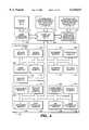
- FIG. 3includes a detailed illustration of the preferred embodiment of the SynRTL library 216 of the present invention.
- the SynRTL library 216includes a set of classes and associated functions.
- the set of classesincludes module classes 300, block classes 302, statement classes 304, expression classes 306, port classes 308, signal classes 310, constant classes 312, package classes 314, branch classes 316, assignment classes 318, process block classes 320, component instantiation classes 322, if block classes 324, if statement classes 326, case statement classes 328, intermediate expression classes 330, and leaf expression classes 332.
- the SynRTL libraryis generated by identifying the common functionality that is inherent in the synthesizable RTL constructs of Verilog and VHDL.
- This aspect of the present inventionidentifies the presence and nature of the common functionality and represents the common functionality using an object-oriented methodology.
- the C++ computer programming languageis used to implement the object-oriented representation.
- the present inventionidentifies the constructs of Verilog and VHDL and groups the constructs into eight categories or objects. The eight categories are defined as the following eight objects.
- Module objects 300--the RTL code for both Verilog and VHDLincludes a hierarchy of modules or entities each of which is represented as a module object in the present invention.
- Concurrent block or concurrent process objects--within a modulethe main body of the RTL code is represented as a set of concurrent blocks or processes that are represented as block objects.
- the types of block objects of the present inventioninclude “always blocks,” “process blocks,” “signal assignment,” and “component instantiation” blocks.
- Statement objects--each concurrent block or processincludes a set of sequential statements, these are represented as statement objects. For synthesizable RTL only a few types of statements are allowed, e.g., IF statements, CASE statements, and assignment statements.
- Expression objects--expressionsare part of statements in both Verilog and VHDL. They appear in assignment statement (or blocks), if statements and case statements.
- Port objects--The ports of a module (or entity)are represented as port objects.
- Signal objects--The two data types of Verilog(reg and wire) are captured within signal objects.
- Constant objects for representing constants--three different types of constantsappear in SynRTL constructs almost exclusively within expressions. For readability of code they may either be named or nameless.
- Package objects--package objectsare used to account for and define the named constants used in the body of RTL code. Package objects can also be used to implement some functions for VHDL.
- HDL independent object-oriented decompositionsare one of the features of the present invention with respect to the design of the SynRTL framework.
- synthesizable RTL codeirrespective of the HDL it is written in, can be decomposed into these HDL independent objects.
- the present inventionidentifies that by reversing this process, the functionality of a hardware module can be represented in terms of these HDL independent objects and synthesizable RTL code can be generated from within these objects in the desired HDL.
- Each of the above identified object categoriesis captured/designed as a C++ class and a hierarchy of classes is created by the present invention. Additional classes have been designed and added to this hierarchy to complete the design of the object-oriented representation of the SynRTL constructs.
- the class definitionsare described below with respect to FIGS. 3-20 where the objects illustrated in FIG. 3 are represented as a C++ class. These classes have a simple and flexible user interface. These design considerations enable the user to easily and robustly map the functionality of the module being generated to an object-hierarchy of these classes using the present invention. Note that the information contained in this object-hierarchy (instantiations of these classes) is the same irrespective of the language in which the RTL code is to be written.
- FIG. 4is a more detailed illustration of the module class 300 according to the preferred embodiment of the present invention.
- the module class 300includes the following functions: an add package declaration module 404, an add port module 406, an add block module 408, an add comments module 410, a create signal module 412, a get constant module 414, a get module name module 416, a get architecture name module 418, a get port module 420, a get signal module 422, a write VHDL port declaration module 424, a write Verilog module 426, and a write VHDL module 428.
- the operation of these moduleswould be apparent to persons skilled in the art.
- the module class 300includes data members such as: module name, architecture name (for VHDL), a list of package declarations (if any), a list of port objects 308, a list of signal objects 310 and a list of block objects 302.
- the port objects 308contain all the information required to declare the port interfaces of this module.
- the signal list in conjunction with the port listis used to identify the signals that need to be declared for this module.
- component declarationsare automatically written out if any component instantiation blocks are present.
- the architecture nameis used to write out the header of the architecture body in VHDL.
- the code for each of the block objectsis written from within the block object (block objects are discussed below) and they together form the main body of code for this module.
- FIG. 5is a more detailed illustration of the block class 302 according to the preferred embodiment of the present invention.
- the block class 302includes: a get label module 504, a get module reference 506, a write Verilog body module 508, a write VHDL declarations module 510, and a write VHDL body module 512.
- the block class 302is an abstract base class from which different types of blocks (concurrent processes) will be derived, for example,--an assignment class 318 for signal assignments, process block class 320 for process/always blocks, a component instantiation class 322 for component instantiations and an IF block class 324 for conditional signal assignments.
- the "write" functionsare implemented as “virtual” functions thereby allowing each derived class to have its own “write” function implementation.
- FIG. 6is a more detailed illustration of the statement class 304 according to the preferred embodiment of the present invention.
- the statement class 304includes a write Verilog body module 608, and a write VHDL body module 610.
- the statement class 304is an abstract base class from which the different types of statements will be derived, such as an assignment class 318 for signal assignments, an IF statement class 326 for ⁇ if-then-else ⁇ constructs and a case statement class 328 for case statements. These are the statements that are supported by synthesis.
- the assignment class 318is derived from both the block class 302 and the statement class 204 thereby allowing it to be identified in both categories. This is an example of a multiple inheritance.
- the "write" functionsare implemented as “virtual" functions thereby allowing each derived class to have its own “write” function implementation.
- FIG. 7is a more detailed illustration of the expression class 306 according to the preferred embodiment of the present invention.
- the expression class 306includes a get OPN module 712, a check expression module 714, a write Verilog expression module 716, and a write VHDL expression module 718.
- the expression classis an abstract base class that acts as a place holder for ⁇ atomic or leaf ⁇ expression objects such as ⁇ constants ⁇ and ⁇ signals ⁇ and for intermediate expression objects constructed from these atomic expressions.
- the intermediate expression class 330implements the intermediate expression objects.
- the "write" functionsare implemented as “virtual" functions thereby allowing each derived class to have its own “write” function implementation.
- FIG. 8is a more detailed illustration of the port class 308 according to the preferred embodiment of the present invention.
- the port class 308includes a get name module 804, a get module reference module 806, a get direction module 808, a get width module 810, a get order module 812, a write Verilog declaration module 814, and a write VHDL declaration module 816.
- the data members of the port class 308include: name, module reference, direction, width and order.
- port objectsare restricted to be either of type single bit, width equal to one (std -- logic in VHDL) or bit vector, width greater than one (std -- logic -- vector in VHDL).
- the syntax for port declarationsare inferred from direction which is either input or output or in/out, and order which is either up or down, the order in which the range is to be declared.
- FIG. 9is a more detailed illustration of the signal class 310 according to the preferred embodiment of the present invention.
- the signal class 310includes a check expression module 906, a get name module 908, a get module reference module 910, a get Verilog type module 912, a get VHDL type string module 914, a get left index module 916, a get right index module 918, a write Verilog expression 920, a write VHDL expression module 922, a write Verilog declaration module 924, and a write VHDL declaration module 926.
- the data members of the signal class 310include: name, module reference, Verilog type, left index and right index.
- Signal objectscan either be of type ⁇ reg ⁇ or ⁇ wire ⁇ in Verilog and this is captured in the Verilog type data member. VHDL does not make such a distinction.
- Signal objectsrequire two different "write" functions for both languages, one to write out signal declaration and the other to write out expression syntax (name).
- FIG. 10is a more detailed illustration of the constant class 312 according to the preferred embodiment of the present invention.
- the constant class 312includes a get name module 1004, a get value module 1006, a get width module 1008, a get VHDL type module 1010, a get Verilog expression module 1012, a get VHDL expression module, a check expression module 1016, a write Verilog expression module 1018, a write Verilog declaration module 1020, a write VHDL expression module 1022, and a write VHDL declaration module.
- the data members of the constant classinclude: name, value and width.
- Constant objectsmay have a name associated with them. If named constants are used then they are declared separately by using, for example, a package class 314 which is described below.
- FIG. 11is a more detailed illustration of the package class 314 according to the preferred embodiment of the present invention.
- the package class 314includes a create package module 1102, an add package declaration module 1106, an add constant module 1110, a get package name module 1112, a get library name module 1114, a get constant module 1116, a write VHDL declaration module 1118, a write Verilog module 1120, and a write VHDL module 1122.
- the data members of the package class 314include: package name, library name, a list of package declarations, a list of (named) constant objects and a list of function objects.
- This classis attuned to capture the syntax and semantics of ⁇ package ⁇ construct in VHDL, however it is also used with Verilog to define the constants as macros.
- the list of function objectsis intended to explicitly define, for VHDL, some of the arithmetic operators which are available as a language feature in Verilog but are not available in VHDL.
- FIG. 12is a more detailed illustration of the branch class 316 according to the preferred embodiment of the present invention.
- the branch class 316includes an add statement module 1202, a get branch expression module 1204, a get statement list size module 1206, a write Verilog expression module 1208, a write Verilog body module 1210, a write VHDL expression module, and a write VHDL body module 1214.
- the branch classcaptures or represents branch execution, e.g., in an IF-THEN-ELSE statement.
- FIG. 13is a more detailed illustration of the assignment class 318 according to the preferred embodiment of the present invention.
- the assignment class 318includes an add expression module 1302, a get expression module 1304, a get target signal module 1306, a get target signal name module 1308, a write Verilog statement module 1310, and a write VHDL statement name 1312.
- the data members of the assignment class 318include: a label, module reference, target signal and the expression that is to be assigned to the target signal.
- the grammar for expressions and the construction of the expression objectis discussed below. This class is also derived from the statement class.
- FIG. 14is a more detailed illustration of the process block class 320 according to the preferred embodiment of the present invention.
- the process block class 320includes an add sensitivity module 1402, an add statement module 1404, a write Verilog body module 1406, and a write VHDL body module 1408.
- the data members of the process block class 320include: a label, module reference, sensitivity list and a list of statement objects.
- the sensitivity listis a list of event structures that include a signal and an edge that can be either ⁇ posedge ⁇ or ⁇ negedge ⁇ or ⁇ level ⁇ , for example.
- a sensitivity listis used for both Verilog and VHDL.
- the body of a process/always blockincludes statements that are provided in the statement list. The code for each of the statement objects is written from within the statement object.
- FIG. 15is a more detailed illustration of the component instantiation class 322 according to the preferred embodiment of the present invention.
- the instantiation class 322includes an add connection module 1502, a get self reference module 1504, a write Verilog body module 1506, a write VHDL declaration module 1508, and a write VHDL body module 1510.
- the data members of the component instantiation class 322include: a label, a module reference, a self reference (to the module being instantiated) and a list of connection structures.
- the name of the instantiated moduleis given by the label.
- Connection structuresconnect signals of this module (module reference) to ports of the module being instantiated (self reference). The component instantiation statements are written out with explicit port signal association.
- FIG. 16is a more detailed illustration of the IF block class 324 according to the preferred embodiment of the present invention.
- the IF block class 324includes an add IF expression module 1602, an add left expression module 1604, an add right expression module 1606, a get target signal module 1608, a get IF expression module 1610, a get left expression module 1612, a get right expression module 1614, a write Verilog body module 1616, and a write VHDL body module 1618.
- the data members of the IF block class 324include: a label, module reference, a target signal, an if expression, a left expression and a right expression.
- the target signalis assigned the left expression if the "if expression” is true or is assigned the right expression if the "if expression” is not true.
- the syntax variations for this block between Verilog and VHDLis handled by the "write" functions.
- This classsupports the following syntax in Verilog, for example: ##EQU1## and the corresponding syntax in VHDL: ##EQU2## Additional syntax can also be supported by the present invention.
- FIG. 17is a more detailed illustration of the IF statement class 326 according to the preferred embodiment of the present invention.
- the IF statement class 326includes an add branch module 1702, a write Verilog body module 1704, and a write VHDL body module 1706.
- the data members of the IF statement class 326include: a list of branch class objects where each branch class objects includes a branch expression (an expression object) and a list of statement objects.
- the ⁇ if-then-else ⁇ constructis viewed as multi-branch construct wherein each branch has a branch expression and if that expression is true the corresponding list of statements is executed. Note that exactly one of the branch expressions will evaluate to be true.
- An example of a typical If statement in Verilogis as follows: ##EQU3## and the corresponding syntax in VHDL: ##EQU4##
- FIG. 18is a more detailed illustration of the case statement class 328 according to the preferred embodiment of the present invention.
- the case statement class 328includes an add branch module 1802, a get case expression 1804, a write Verilog body 1806, and a write VHDL body 1808.
- the data members of the case statement class 328include: a case expression (an expression object) and a list of branch class objects.
- the case expressionis typically a signal object and the branch expressions of the branch class objects correspond to the various possible values the case expression (signal) can take.
- These branch expressionsare typically constant objects. For each branch a list of statement objects is required.
- FIG. 19is a more detailed illustration of the intermediate expression class 330 according to the preferred embodiment of the present invention.
- the intermediate expression class 330includes a check expression module 1908, an add left expression module 1910, an add right expression module 1912, a get OPN module 1914, a get operand module 1916, a get Verilog operand module 1918, a get VHDL operand module 1920, a write Verilog expression module 1922, and a write VHDL expression module 1924.
- the data members of the intermediate expression class 330include: an operation (no opn or event or unary or binary), an operator type (boolean and logic operators such as ⁇ not ⁇ , ⁇ and ⁇ , ⁇ or ⁇ ; arithmetic operators such as ⁇ + ⁇ , ⁇ * ⁇ etc., and event operators for signal events), a left expression and a right expression.
- an operationno opn or event or unary or binary
- an operator typeboolean and logic operators such as ⁇ not ⁇ , ⁇ and ⁇ , ⁇ or ⁇
- arithmetic operatorssuch as ⁇ + ⁇ , ⁇ * ⁇ etc.
- event operators for signal eventsa left expression and a right expression.
- This grammarallows for the construction of arbitrary expressions.
- FIG. 20is a more detailed illustration of the leaf expression class 332 according to the preferred embodiment of the present invention.
- the leaf expression classincludes a get OPN module 2002.
- the leaf expression class 332is an abstract class that acts as a place holder for signal class and constant class which are the two possible atomic or leaf level expression objects.
- the above described classes of the present inventioncapture the synthesizable constructs of both Verilog and VHDL. These classes have been implemented and compiled as a library archive.
- the user(software tool) can link to this library archive and instantiate a hierarchy of objects corresponding to the functionality of the module to be generated during the second portion of the present invention, i.e., the use of the SynRTL library to generate an HDL independent design representation.
- the system and method of this second portionis set forth below.
- FIG. 21illustrates a computer system 2100 in which system level RTL hardware designs are generated using the SynRTL library 216.
- the computer system 2100includes a processor 2102, I/O device 2104, and memory 2106, 2108.
- non-volatile memory 2106 and volatile memory 2108are used.
- An I/O interface 2108 and the executable object code 118, representing an HDL independent RTL hardware design software tool,are stored within the volatile memory.
- the executable object code(with the SynRTL library compiled therein) is executed within the processor to produce an RTL design representation 2112.
- This RTL design representation 2112may be a Verilog or VHDL HDL code or any other type of representation of RTL constructs.
- FIG. 22is a more detailed illustration of the computer system 2100 in which System level RTL Hardware designs are generated using the SynRTL library 216.
- the processor 2102is a microprocessor of a UNIX workstation 2202
- I/O device 2104is the monitor, keyboard, and mouse (collectively 2202) of a UNIX workstation 2200.
- the non-volatile memory 2106is a hard disk storage device 2204.
- the microprocessor of workstation 2200does not directly communicate with the hard disk storage 2204. However, in alternative embodiments, the hard disk storage 2204 is coupled directly to the microprocessor.
- the I/O interface 2110is a graphical user interface (GUI) 2208, such as X-windows, from the Massachusetts Institute of Technology (MIT).
- GUIgraphical user interface
- MITMassachusetts Institute of Technology
- the preferred embodimentgenerates VHDL and/or Verilog RTL code 2212 that is stored in UNIX files.
- FIG. 23is a detailed illustration of the preferred embodiment of an HDL independent system level RTL hardware design software tool 118 of the present invention.
- the toolresides in volatile memory 2206 along with GUI 2208, and interfaces with the monitor, keyboard, and mouse (collectively 2202) of a UNIX workstation.
- the preferred embodiment of the software tool 118includes an HDL independent system level RTL design receiver 2300, which produces a system level RTL design representation 2308 based on the input from a hardware designer through the I/O device 2202.
- the system level RTL design representation 2308is then translated into HDL independent RTL constructs 2310 by the system level to RTL code translator 2302.
- the HDL independent RTL constructs 2310are then transformed into either Verilog or VHDL code 2312 by the HDL code generator 2304.
- FIG. 24is a flow diagram illustrating the preferred method the of the code execution part of the present invention.
- a userdefines a system level RTL hardware design 2400.
- a system level RTL hardware designis a behavioral representation of a system which is independent of the particular target technology. Often, system level RTL hardware design includes connecting various predefined hardware modules in order to achieve some behavior.
- a hardware moduleis a representation of some specific functionality. An example of a hardware module is an up-down counter.
- the present inventionAfter a system level hardware design is defined, 2400, the present invention generates 2402 a register transfer level representation of the system from the system level hardware design.
- a register transfer level representationdescribes modules in terms of signals which are generated and propagated through combinational modules from one set of registers to another set of registers.
- the current inventiongenerates a register transfer level representation that is independent of any HDL, and that includes only synthesizable constructs, as described above.
- HDL codecan be "synthesized" into gate level netlists, the process of transforming HDL code into a form which can be used by a particular integrated circuit manufacturer to create an integrated circuit.
- Another possibilityis to generate a gate netlist directly from the intermediate register transfer level representation, 2408. In such a case, the ultimate design will never have been represented in a Hardware Description Language at all.
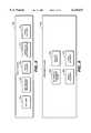
- FIG. 25is an object relation diagram using standard "booch” notation illustrating the hierarchy of objects in the SynRTL library. The relations between the various objects is shown in FIG. 25 in the conventional "booch” notation.
- By invoking the "write” function of the module objectthe entire body of code for that module is written out.
- the "write" functions of the various objects in this hierarchyare recursively invoked when appropriate, making the method of the present invention a true object-oriented solution.
- FIG. 25sets forth the description of how a user generates the HDL independent code. Given the above description the operation of the invention will be apparent to persons skilled in the art.
- FIG. 26is an illustration of an up-down counter described using synthesizable Verilog code.
- FIG. 27is an illustration of an up-down counter described using synthesizable VHDL code.
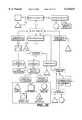
- FIG. 28is an illustration of the object hierarchy for an up-down counter using the SynRTL library 116 of the present invention.
- FIG. 28The method for generating an up-down counter, for example, is illustrated in general in FIG. 28.
- the RTL code for an up-down counter in synthesizable Verilogis shown in FIG. 26.
- the RTL code for the same module in VHDLis shown in FIG. 27.
- the RTL code shown in FIGS. 26 and 27are used to illustrate how the HDL independent object hierarchy is created for an up-down counter according to the preferred embodiment of the present invention.
- a module class object 300is instantiated with the module name "up -- down -- cnt".
- the port class 308 objectsare instantiated for clk, rst, up dn and out ports and added to the module class object 300.
- Signal class objects 310are instantiated for clk, rst, up -- dn, out, int -- out and outl and are added to the module class object 300.
- two process block class objects 320 and an assignment class object 318are instantiated. These are added to the block list 302 of the module class object 300.
- the first block objectcorresponds to the up-dn combinational process
- the second block objectcorresponds. to the sequential process
- the last block objectcorresponds to the concurrent signal assignment block.
- the first process block class objectis filled with an IF statement class 326 object with three branches and the second one is filled with an IF statement class 326 object with two branches.
- the decomposition of the assignment class 318 at the block level and statement levelis not shown.
- the decomposition of expression class objects 306are also not shown as the use of these objects will be apparent to those skilled in the art.
- Any software tool which needs to generate an up down countercan use the SynRTL framework of the present invention and create the object-hierarchy illustrated in FIG. 28. This is accomplished by linking to the SynRTL library archive and using the member functions of the classes. Verilog code as shown in FIG. 26, or VHDL code as shown in FIG. 27 can then be generated by invoking the member "write" functions of the module class 300.
Landscapes
- Engineering & Computer Science (AREA)
- Computer Hardware Design (AREA)
- Physics & Mathematics (AREA)
- Theoretical Computer Science (AREA)
- Evolutionary Computation (AREA)
- Geometry (AREA)
- General Engineering & Computer Science (AREA)
- General Physics & Mathematics (AREA)
- Stored Programmes (AREA)
Abstract
Description
Claims (15)
Priority Applications (1)
| Application Number | Priority Date | Filing Date | Title |
|---|---|---|---|
| US08/956,874US6135647A (en) | 1997-10-23 | 1997-10-23 | System and method for representing a system level RTL design using HDL independent objects and translation to synthesizable RTL code |
Applications Claiming Priority (1)
| Application Number | Priority Date | Filing Date | Title |
|---|---|---|---|
| US08/956,874US6135647A (en) | 1997-10-23 | 1997-10-23 | System and method for representing a system level RTL design using HDL independent objects and translation to synthesizable RTL code |
Publications (1)
| Publication Number | Publication Date |
|---|---|
| US6135647Atrue US6135647A (en) | 2000-10-24 |
Family
ID=25498802
Family Applications (1)
| Application Number | Title | Priority Date | Filing Date |
|---|---|---|---|
| US08/956,874Expired - LifetimeUS6135647A (en) | 1997-10-23 | 1997-10-23 | System and method for representing a system level RTL design using HDL independent objects and translation to synthesizable RTL code |
Country Status (1)
| Country | Link |
|---|---|
| US (1) | US6135647A (en) |
Cited By (46)
| Publication number | Priority date | Publication date | Assignee | Title |
|---|---|---|---|---|
| US20010021903A1 (en)* | 1999-12-02 | 2001-09-13 | Hiroshi Ryu | Method, and apparatus for simulating a system using an object oriented language |
| US6438735B1 (en)* | 1999-05-17 | 2002-08-20 | Synplicity, Inc. | Methods and apparatuses for designing integrated circuits |
| US20030023576A1 (en)* | 2000-12-22 | 2003-01-30 | Kent Gilson | Viva |
| US6519754B1 (en) | 1999-05-17 | 2003-02-11 | Synplicity, Inc. | Methods and apparatuses for designing integrated circuits |
| US6529913B1 (en)* | 1999-10-15 | 2003-03-04 | Cadence Design Systems, Inc. | Database for electronic design automation applications |
| US20030046649A1 (en)* | 2001-08-28 | 2003-03-06 | Wheeler William R. | Model-based logic design |
| US6591403B1 (en)* | 2000-10-02 | 2003-07-08 | Hewlett-Packard Development Company, L.P. | System and method for specifying hardware description language assertions targeting a diverse set of verification tools |
| US6640329B2 (en) | 2001-08-29 | 2003-10-28 | Intel Corporation | Real-time connection error checking method and process |
| US20030204386A1 (en)* | 2002-04-24 | 2003-10-30 | Glenn Colon-Bonet | Class-based system for circuit modeling |
| US6643836B2 (en) | 2001-08-29 | 2003-11-04 | Intel Corporation | Displaying information relating to a logic design |
| US6658630B1 (en)* | 2000-11-09 | 2003-12-02 | Lsi Logic Corporation | Method to translate UDPs using gate primitives |
| US20030229482A1 (en)* | 2002-04-25 | 2003-12-11 | Cook Stephen Anthony | Apparatus and method for managing integrated circuit designs |
| US6708321B2 (en) | 2001-08-29 | 2004-03-16 | Intel Corporation | Generating a function within a logic design using a dialog box |
| US6721925B2 (en) | 2001-08-29 | 2004-04-13 | Intel Corporation | Employing intelligent logical models to enable concise logic representations for clarity of design description and for rapid design capture |
| US20040093198A1 (en)* | 2002-11-08 | 2004-05-13 | Carbon Design Systems | Hardware simulation with access restrictions |
| US6859913B2 (en) | 2001-08-29 | 2005-02-22 | Intel Corporation | Representing a simulation model using a hardware configuration database |
| EP1517254A2 (en) | 2003-09-20 | 2005-03-23 | Spiratech Limited | Modelling and simulation method |
| US20050076314A1 (en)* | 2001-02-02 | 2005-04-07 | Kabushiki Kaisha Toshiba | System LSI development apparatus and the method thereof for developing a system optimal to an application |
| US20050120324A1 (en)* | 2003-12-02 | 2005-06-02 | Nec Corporation | Integrated circuit designing support apparatus and method for the same |
| US20050229170A1 (en)* | 2004-04-08 | 2005-10-13 | Matthew Bellantoni | Optimized system-level simulation |
| US20050228628A1 (en)* | 2004-04-08 | 2005-10-13 | Matthew Bellantoni | System-level simulation of interconnected devices |
| US20050228627A1 (en)* | 2004-04-08 | 2005-10-13 | Matthew Bellantoni | System-level simulation of devices having diverse timing |
| US6957423B1 (en)* | 2001-05-15 | 2005-10-18 | Xilinx, Inc. | Method of inlining a VHDL function call into Verilog |
| US6983427B2 (en) | 2001-08-29 | 2006-01-03 | Intel Corporation | Generating a logic design |
| US20060053396A1 (en)* | 1998-01-30 | 2006-03-09 | Tera Systems, Inc. | Creating optimized physical implementations from high-level descriptions of electronic design using placement-based information |
| US20060085176A1 (en)* | 2004-10-14 | 2006-04-20 | Matthew Bellantoni | Generating an optimized system-level simulation |
| US7073156B2 (en) | 2001-08-29 | 2006-07-04 | Intel Corporation | Gate estimation process and method |
| US7082104B2 (en) | 2001-05-18 | 2006-07-25 | Intel Corporation | Network device switch |
| US7107201B2 (en) | 2001-08-29 | 2006-09-12 | Intel Corporation | Simulating a logic design |
| US7130784B2 (en) | 2001-08-29 | 2006-10-31 | Intel Corporation | Logic simulation |
| US20060282801A1 (en)* | 2004-05-12 | 2006-12-14 | Juergen Lahner | Enhanced method of optimizing multiplex structures and multiplex control structures in rtl code |
| US7197724B2 (en) | 2002-01-17 | 2007-03-27 | Intel Corporation | Modeling a logic design |
| US7272542B1 (en)* | 2001-04-30 | 2007-09-18 | Xilinx, Inc. | Method and system for re-targeting integrated circuits |
| US7363599B1 (en) | 2005-10-04 | 2008-04-22 | Xilinx, Inc. | Method and system for matching a hierarchical identifier |
| US20080098339A1 (en)* | 2004-10-01 | 2008-04-24 | Chan Terence W | Racecheck: a race logic analyzer program for digital integrated circuits |
| US7380232B1 (en) | 2006-03-10 | 2008-05-27 | Xilinx, Inc. | Method and apparatus for designing a system for implementation in a programmable logic device |
| US7386814B1 (en)* | 2005-02-10 | 2008-06-10 | Xilinx, Inc. | Translation of high-level circuit design blocks into hardware description language |
| US7493578B1 (en) | 2005-03-18 | 2009-02-17 | Xilinx, Inc. | Correlation of data from design analysis tools with design blocks in a high-level modeling system |
| US7496869B1 (en)* | 2005-10-04 | 2009-02-24 | Xilinx, Inc. | Method and apparatus for implementing a program language description of a circuit design for an integrated circuit |
| US7761272B1 (en) | 2006-03-10 | 2010-07-20 | Xilinx, Inc. | Method and apparatus for processing a dataflow description of a digital processing system |
| US20110289298A1 (en)* | 2010-05-19 | 2011-11-24 | Fujitsu Semiconductor Limited | Semiconductor circuit and designing apparatus |
| US8402409B1 (en) | 2006-03-10 | 2013-03-19 | Xilinx, Inc. | Method and apparatus for supporting run-time reconfiguration in a programmable logic integrated circuit |
| US8639487B1 (en)* | 2003-03-25 | 2014-01-28 | Cadence Design Systems, Inc. | Method for multiple processor system-on-a-chip hardware and software cogeneration |
| US9201999B1 (en)* | 2014-06-30 | 2015-12-01 | Cadence Design Systems, Inc. | Integrated circuit floorplan having feedthrough buffers |
| EP1426885B1 (en)* | 2002-12-04 | 2017-01-04 | Mentor Graphics Corporation | Generation of a multiplicity of parameterised HDLs |
| US20220012392A1 (en)* | 2020-07-10 | 2022-01-13 | Taiwan Semiconductor Manufacturing Company Limited | Systems and Methods for Generating Synthesizable Netlists From Register Transfer Level Designs |
Citations (8)
| Publication number | Priority date | Publication date | Assignee | Title |
|---|---|---|---|---|
| US5487018A (en)* | 1993-08-13 | 1996-01-23 | Vlsi Technology, Inc. | Electronic design automation apparatus and method utilizing a physical information database |
| US5519627A (en)* | 1992-05-01 | 1996-05-21 | Vlsi Technology, Inc. | Datapath synthesis method and apparatus utilizing a structured cell library |
| US5530841A (en)* | 1990-12-21 | 1996-06-25 | Synopsys, Inc. | Method for converting a hardware independent user description of a logic circuit into hardware components |
| US5537580A (en)* | 1994-12-21 | 1996-07-16 | Vlsi Technology, Inc. | Integrated circuit fabrication using state machine extraction from behavioral hardware description language |
| US5812416A (en)* | 1996-07-18 | 1998-09-22 | Lsi Logic Corporation | Integrated circuit design decomposition |
| US5841663A (en)* | 1995-09-14 | 1998-11-24 | Vlsi Technology, Inc. | Apparatus and method for synthesizing integrated circuits using parameterized HDL modules |
| US5867399A (en)* | 1990-04-06 | 1999-02-02 | Lsi Logic Corporation | System and method for creating and validating structural description of electronic system from higher-level and behavior-oriented description |
| US5880971A (en)* | 1990-04-06 | 1999-03-09 | Lsi Logic Corporation | Methodology for deriving executable low-level structural descriptions and valid physical implementations of circuits and systems from semantic specifications and descriptions thereof |
- 1997
- 1997-10-23USUS08/956,874patent/US6135647A/ennot_activeExpired - Lifetime
Patent Citations (10)
| Publication number | Priority date | Publication date | Assignee | Title |
|---|---|---|---|---|
| US5867399A (en)* | 1990-04-06 | 1999-02-02 | Lsi Logic Corporation | System and method for creating and validating structural description of electronic system from higher-level and behavior-oriented description |
| US5880971A (en)* | 1990-04-06 | 1999-03-09 | Lsi Logic Corporation | Methodology for deriving executable low-level structural descriptions and valid physical implementations of circuits and systems from semantic specifications and descriptions thereof |
| US5530841A (en)* | 1990-12-21 | 1996-06-25 | Synopsys, Inc. | Method for converting a hardware independent user description of a logic circuit into hardware components |
| US5581781A (en)* | 1990-12-21 | 1996-12-03 | Synopsys, Inc. | Synthesizer for generating a logic network using a hardware independent description |
| US5953235A (en)* | 1990-12-21 | 1999-09-14 | Synopsys, Inc. | Method for processing a hardware independent user description to generate logic circuit elements including flip-flops, latches, and three-state buffers and combinations thereof |
| US5519627A (en)* | 1992-05-01 | 1996-05-21 | Vlsi Technology, Inc. | Datapath synthesis method and apparatus utilizing a structured cell library |
| US5487018A (en)* | 1993-08-13 | 1996-01-23 | Vlsi Technology, Inc. | Electronic design automation apparatus and method utilizing a physical information database |
| US5537580A (en)* | 1994-12-21 | 1996-07-16 | Vlsi Technology, Inc. | Integrated circuit fabrication using state machine extraction from behavioral hardware description language |
| US5841663A (en)* | 1995-09-14 | 1998-11-24 | Vlsi Technology, Inc. | Apparatus and method for synthesizing integrated circuits using parameterized HDL modules |
| US5812416A (en)* | 1996-07-18 | 1998-09-22 | Lsi Logic Corporation | Integrated circuit design decomposition |
Cited By (83)
| Publication number | Priority date | Publication date | Assignee | Title |
|---|---|---|---|---|
| US20060053396A1 (en)* | 1998-01-30 | 2006-03-09 | Tera Systems, Inc. | Creating optimized physical implementations from high-level descriptions of electronic design using placement-based information |
| US20030149954A1 (en)* | 1999-05-17 | 2003-08-07 | Mcelvain Kenneth S. | Methods and apparatuses for designing integrated circuits |
| US20040117756A1 (en)* | 1999-05-17 | 2004-06-17 | Mcelvain Kenneth S. | Methods and apparatuses for designing integrated circuits |
| US6519754B1 (en) | 1999-05-17 | 2003-02-11 | Synplicity, Inc. | Methods and apparatuses for designing integrated circuits |
| US7275233B2 (en)* | 1999-05-17 | 2007-09-25 | Synplicity, Inc. | Methods and apparatuses for designing integrated circuits |
| US20070288871A1 (en)* | 1999-05-17 | 2007-12-13 | Mcelvain Kenneth S | Methods and apparatuses for designing integrated circuits |
| US20030079195A1 (en)* | 1999-05-17 | 2003-04-24 | Mcelvain Kenneth S. | Methods and apparatuses for designing integrated circuits |
| US7454732B2 (en)* | 1999-05-17 | 2008-11-18 | Synopsys, Inc. | Methods and apparatuses for designing integrated circuits (ICs) with optimization at register transfer level (RTL) amongst multiple ICs |
| US6978430B2 (en)* | 1999-05-17 | 2005-12-20 | Synplicity, Inc. | Methods and apparatuses for designing integrated circuits |
| US7010769B2 (en) | 1999-05-17 | 2006-03-07 | Synplicity, Inc. | Methods and apparatuses for designing integrated circuits |
| US7631282B2 (en) | 1999-05-17 | 2009-12-08 | Synopsys, Inc. | Methods and apparatuses for designing integrated circuits |
| US6438735B1 (en)* | 1999-05-17 | 2002-08-20 | Synplicity, Inc. | Methods and apparatuses for designing integrated circuits |
| US20060053401A1 (en)* | 1999-05-17 | 2006-03-09 | Mcelvain Kenneth S | Methods and apparatuses for designing integrated circuits |
| US6668364B2 (en)* | 1999-05-17 | 2003-12-23 | Synplicity, Inc. | Methods and apparatuses for designing integrated circuits |
| US6529913B1 (en)* | 1999-10-15 | 2003-03-04 | Cadence Design Systems, Inc. | Database for electronic design automation applications |
| US20010021903A1 (en)* | 1999-12-02 | 2001-09-13 | Hiroshi Ryu | Method, and apparatus for simulating a system using an object oriented language |
| US6882966B2 (en)* | 1999-12-02 | 2005-04-19 | Nec Electronics Corporation | Method, and apparatus for simulating a system using an object oriented language |
| US6591403B1 (en)* | 2000-10-02 | 2003-07-08 | Hewlett-Packard Development Company, L.P. | System and method for specifying hardware description language assertions targeting a diverse set of verification tools |
| US6658630B1 (en)* | 2000-11-09 | 2003-12-02 | Lsi Logic Corporation | Method to translate UDPs using gate primitives |
| US20070150858A1 (en)* | 2000-12-22 | 2007-06-28 | Star Bridge Systems, Inc. | Behavioral synthesis methods for generating computer-executable code |
| US20070130196A1 (en)* | 2000-12-22 | 2007-06-07 | Star Bridge Systems, Inc. | Removing data set exposers and collectors from behavioral design code |
| US20030023576A1 (en)* | 2000-12-22 | 2003-01-30 | Kent Gilson | Viva |
| EP1346283A4 (en)* | 2000-12-22 | 2005-09-21 | Star Bridge Systems Inc | Viva |
| US7197505B2 (en) | 2000-12-22 | 2007-03-27 | Star Bridge Systems, Inc. | Multi-dimensional recursive wavefront behavioral synthesis |
| US20070150501A1 (en)* | 2000-12-22 | 2007-06-28 | Star Bridge Systems, Inc. | Conversion of data sets between data set types |
| US7525457B2 (en) | 2000-12-22 | 2009-04-28 | Star Bridge Systems, Inc. | Transforming design objects in a computer by converting data sets between data set types |
| US20050076314A1 (en)* | 2001-02-02 | 2005-04-07 | Kabushiki Kaisha Toshiba | System LSI development apparatus and the method thereof for developing a system optimal to an application |
| US7340692B2 (en)* | 2001-02-02 | 2008-03-04 | Kabushiki Kaisha Toshiba | System LSI development apparatus and the method thereof for developing a system optimal to an application |
| US7272542B1 (en)* | 2001-04-30 | 2007-09-18 | Xilinx, Inc. | Method and system for re-targeting integrated circuits |
| US6957423B1 (en)* | 2001-05-15 | 2005-10-18 | Xilinx, Inc. | Method of inlining a VHDL function call into Verilog |
| US7082104B2 (en) | 2001-05-18 | 2006-07-25 | Intel Corporation | Network device switch |
| US7093224B2 (en)* | 2001-08-28 | 2006-08-15 | Intel Corporation | Model-based logic design |
| US20030046649A1 (en)* | 2001-08-28 | 2003-03-06 | Wheeler William R. | Model-based logic design |
| US6983427B2 (en) | 2001-08-29 | 2006-01-03 | Intel Corporation | Generating a logic design |
| US7107201B2 (en) | 2001-08-29 | 2006-09-12 | Intel Corporation | Simulating a logic design |
| US6859913B2 (en) | 2001-08-29 | 2005-02-22 | Intel Corporation | Representing a simulation model using a hardware configuration database |
| US6640329B2 (en) | 2001-08-29 | 2003-10-28 | Intel Corporation | Real-time connection error checking method and process |
| US6721925B2 (en) | 2001-08-29 | 2004-04-13 | Intel Corporation | Employing intelligent logical models to enable concise logic representations for clarity of design description and for rapid design capture |
| US6708321B2 (en) | 2001-08-29 | 2004-03-16 | Intel Corporation | Generating a function within a logic design using a dialog box |
| US7130784B2 (en) | 2001-08-29 | 2006-10-31 | Intel Corporation | Logic simulation |
| US7073156B2 (en) | 2001-08-29 | 2006-07-04 | Intel Corporation | Gate estimation process and method |
| US6643836B2 (en) | 2001-08-29 | 2003-11-04 | Intel Corporation | Displaying information relating to a logic design |
| US7197724B2 (en) | 2002-01-17 | 2007-03-27 | Intel Corporation | Modeling a logic design |
| US20030204386A1 (en)* | 2002-04-24 | 2003-10-30 | Glenn Colon-Bonet | Class-based system for circuit modeling |
| CN102902839B (en)* | 2002-04-25 | 2016-04-06 | 新思科技公司 | The apparatus and method of management integrated circuit (IC) design |
| US20030229482A1 (en)* | 2002-04-25 | 2003-12-11 | Cook Stephen Anthony | Apparatus and method for managing integrated circuit designs |
| US7475000B2 (en)* | 2002-04-25 | 2009-01-06 | Arc International, Plc | Apparatus and method for managing integrated circuit designs |
| CN102902839A (en)* | 2002-04-25 | 2013-01-30 | Arc国际公司 | Apparatus and method for managing integrated circuit designs |
| US20040117167A1 (en)* | 2002-11-08 | 2004-06-17 | William Neifert | Simulation of software objects generated from a hardware description |
| US20040117168A1 (en)* | 2002-11-08 | 2004-06-17 | William Neifert | Global analysis of software objects generated from a hardware description |
| US20040093198A1 (en)* | 2002-11-08 | 2004-05-13 | Carbon Design Systems | Hardware simulation with access restrictions |
| US20040122644A1 (en)* | 2002-11-08 | 2004-06-24 | William Neifert | Optimized execution of software objects generated from a hardware description |
| US20050055675A1 (en)* | 2002-11-08 | 2005-03-10 | William Neifert | Generation of software objects from a hardware description |
| EP1426885B1 (en)* | 2002-12-04 | 2017-01-04 | Mentor Graphics Corporation | Generation of a multiplicity of parameterised HDLs |
| US8639487B1 (en)* | 2003-03-25 | 2014-01-28 | Cadence Design Systems, Inc. | Method for multiple processor system-on-a-chip hardware and software cogeneration |
| US20050091026A1 (en)* | 2003-09-20 | 2005-04-28 | Spiratech Limited | Modelling and simulation method |
| EP1517254A3 (en)* | 2003-09-20 | 2005-11-16 | Spiratech Limited | Modelling and simulation method |
| US10409937B2 (en) | 2003-09-20 | 2019-09-10 | Mentor Graphics Corporation | Modelling and simulation method |
| US9323873B2 (en) | 2003-09-20 | 2016-04-26 | Mentor Graphics Corporation | Modelling and simulation method |
| EP1517254A2 (en) | 2003-09-20 | 2005-03-23 | Spiratech Limited | Modelling and simulation method |
| US8082141B2 (en) | 2003-09-20 | 2011-12-20 | Mentor Graphics Corporation | Modelling and simulation method |
| US7234127B2 (en)* | 2003-12-02 | 2007-06-19 | Nec Corporation | Integrated circuit designing support apparatus and method for the same |
| US20050120324A1 (en)* | 2003-12-02 | 2005-06-02 | Nec Corporation | Integrated circuit designing support apparatus and method for the same |
| US20050228627A1 (en)* | 2004-04-08 | 2005-10-13 | Matthew Bellantoni | System-level simulation of devices having diverse timing |
| US20050229170A1 (en)* | 2004-04-08 | 2005-10-13 | Matthew Bellantoni | Optimized system-level simulation |
| US20050228628A1 (en)* | 2004-04-08 | 2005-10-13 | Matthew Bellantoni | System-level simulation of interconnected devices |
| US7594201B2 (en)* | 2004-05-12 | 2009-09-22 | Lsi Corporation | Enhanced method of optimizing multiplex structures and multiplex control structures in RTL code |
| US20060282801A1 (en)* | 2004-05-12 | 2006-12-14 | Juergen Lahner | Enhanced method of optimizing multiplex structures and multiplex control structures in rtl code |
| US20080098339A1 (en)* | 2004-10-01 | 2008-04-24 | Chan Terence W | Racecheck: a race logic analyzer program for digital integrated circuits |
| US7757191B2 (en)* | 2004-10-01 | 2010-07-13 | Chan Terence Wai-Kwok | Racecheck: a race logic analyzer program for digital integrated circuits |
| US20060085176A1 (en)* | 2004-10-14 | 2006-04-20 | Matthew Bellantoni | Generating an optimized system-level simulation |
| US7386814B1 (en)* | 2005-02-10 | 2008-06-10 | Xilinx, Inc. | Translation of high-level circuit design blocks into hardware description language |
| US7685541B1 (en) | 2005-02-10 | 2010-03-23 | Xilinx, Inc. | Translation of high-level circuit design blocks into hardware description language |
| US7493578B1 (en) | 2005-03-18 | 2009-02-17 | Xilinx, Inc. | Correlation of data from design analysis tools with design blocks in a high-level modeling system |
| US7496869B1 (en)* | 2005-10-04 | 2009-02-24 | Xilinx, Inc. | Method and apparatus for implementing a program language description of a circuit design for an integrated circuit |
| US7363599B1 (en) | 2005-10-04 | 2008-04-22 | Xilinx, Inc. | Method and system for matching a hierarchical identifier |
| US7761272B1 (en) | 2006-03-10 | 2010-07-20 | Xilinx, Inc. | Method and apparatus for processing a dataflow description of a digital processing system |
| US8402409B1 (en) | 2006-03-10 | 2013-03-19 | Xilinx, Inc. | Method and apparatus for supporting run-time reconfiguration in a programmable logic integrated circuit |
| US7380232B1 (en) | 2006-03-10 | 2008-05-27 | Xilinx, Inc. | Method and apparatus for designing a system for implementation in a programmable logic device |
| US20110289298A1 (en)* | 2010-05-19 | 2011-11-24 | Fujitsu Semiconductor Limited | Semiconductor circuit and designing apparatus |
| US9201999B1 (en)* | 2014-06-30 | 2015-12-01 | Cadence Design Systems, Inc. | Integrated circuit floorplan having feedthrough buffers |
| US20220012392A1 (en)* | 2020-07-10 | 2022-01-13 | Taiwan Semiconductor Manufacturing Company Limited | Systems and Methods for Generating Synthesizable Netlists From Register Transfer Level Designs |
| US12175175B2 (en)* | 2020-07-10 | 2024-12-24 | Taiwan Semiconductor Manufacturing Company Limited | Systems and methods for generating synthesizable netlists from register transfer level designs |
Similar Documents
| Publication | Publication Date | Title |
|---|---|---|
| US6135647A (en) | System and method for representing a system level RTL design using HDL independent objects and translation to synthesizable RTL code | |
| Sutherland et al. | SystemVerilog for Design: A guide to using SystemVerilog for hardware design and modeling | |
| US6557156B1 (en) | Method of configuring FPGAS for dynamically reconfigurable computing | |
| US7328195B2 (en) | Semi-automatic generation of behavior models continuous value using iterative probing of a device or existing component model | |
| US7805690B2 (en) | Method for generating compiler, simulation, synthesis and test suite from a common processor specification | |
| US6701501B2 (en) | Structured algorithmic programming language approach to system design | |
| US6606734B2 (en) | Simulation method and compiler for hardware/software programming | |
| WO2011156234A1 (en) | Systems and methods for circuit design, synthesis, simulation, and modeling | |
| US8881074B2 (en) | Device and method for refactoring hardware code | |
| US20030237078A1 (en) | Incorporating simulation analysis instrumentation into HDL models | |
| US6952817B1 (en) | Generating hardware interfaces for designs specified in a high level language | |
| US7509246B1 (en) | System level simulation models for hardware modules | |
| Lööw | Reconciling verified-circuit development and Verilog development | |
| Blaumenrohr et al. | Performing high-level synthesis via program transformations within a theorem prover | |
| Wirthlin et al. | Synthesizing RTL hardware from Java byte codes | |
| Gauthier et al. | HDLRuby, a new high productivity hardware description language | |
| Gries et al. | The mescal architecture development system (tipi) tutorial | |
| Vahid et al. | SpecCharts: A language for system level specification and synthesis | |
| Ang et al. | On linking RT-component functionality to abstract HDL behavior | |
| Chen | A VHDL front end | |
| Bergé et al. | M and VHDL | |
| Michaelson et al. | The Hume Report, Version 0.2 | |
| Khan | Automatic generation of transactors in SystemC | |
| Patentariu et al. | SOME CONSIDERATIIONS ON 8-LEVEL HDL STACK IMPLEMENTATION | |
| Maurer | The Functional Hardware Design Language |
Legal Events
| Date | Code | Title | Description |
|---|---|---|---|
| AS | Assignment | Owner name:LSI LOGIC CORPORATION, CALIFORNIA Free format text:ASSIGNMENT OF ASSIGNORS INTEREST;ASSIGNORS:BALAKRISHNAN, ARUN;DE, KAUSHIK;QIAN, JUN;REEL/FRAME:008865/0410;SIGNING DATES FROM 19971016 TO 19971017 | |
| STCF | Information on status: patent grant | Free format text:PATENTED CASE | |
| FPAY | Fee payment | Year of fee payment:4 | |
| FEPP | Fee payment procedure | Free format text:PAYOR NUMBER ASSIGNED (ORIGINAL EVENT CODE: ASPN); ENTITY STATUS OF PATENT OWNER: LARGE ENTITY Free format text:PAYER NUMBER DE-ASSIGNED (ORIGINAL EVENT CODE: RMPN); ENTITY STATUS OF PATENT OWNER: LARGE ENTITY | |
| FPAY | Fee payment | Year of fee payment:8 | |
| FPAY | Fee payment | Year of fee payment:12 | |
| AS | Assignment | Owner name:DEUTSCHE BANK AG NEW YORK BRANCH, AS COLLATERAL AG Free format text:PATENT SECURITY AGREEMENT;ASSIGNORS:LSI CORPORATION;AGERE SYSTEMS LLC;REEL/FRAME:032856/0031 Effective date:20140506 | |
| AS | Assignment | Owner name:LSI CORPORATION, CALIFORNIA Free format text:CHANGE OF NAME;ASSIGNOR:LSI LOGIC CORPORATION;REEL/FRAME:033102/0270 Effective date:20070406 | |
| AS | Assignment | Owner name:AVAGO TECHNOLOGIES GENERAL IP (SINGAPORE) PTE. LTD Free format text:ASSIGNMENT OF ASSIGNORS INTEREST;ASSIGNOR:LSI CORPORATION;REEL/FRAME:035390/0388 Effective date:20140814 | |
| AS | Assignment | Owner name:LSI CORPORATION, CALIFORNIA Free format text:TERMINATION AND RELEASE OF SECURITY INTEREST IN PATENT RIGHTS (RELEASES RF 032856-0031);ASSIGNOR:DEUTSCHE BANK AG NEW YORK BRANCH, AS COLLATERAL AGENT;REEL/FRAME:037684/0039 Effective date:20160201 Owner name:AGERE SYSTEMS LLC, PENNSYLVANIA Free format text:TERMINATION AND RELEASE OF SECURITY INTEREST IN PATENT RIGHTS (RELEASES RF 032856-0031);ASSIGNOR:DEUTSCHE BANK AG NEW YORK BRANCH, AS COLLATERAL AGENT;REEL/FRAME:037684/0039 Effective date:20160201 | |
| AS | Assignment | Owner name:BANK OF AMERICA, N.A., AS COLLATERAL AGENT, NORTH CAROLINA Free format text:PATENT SECURITY AGREEMENT;ASSIGNOR:AVAGO TECHNOLOGIES GENERAL IP (SINGAPORE) PTE. LTD.;REEL/FRAME:037808/0001 Effective date:20160201 Owner name:BANK OF AMERICA, N.A., AS COLLATERAL AGENT, NORTH Free format text:PATENT SECURITY AGREEMENT;ASSIGNOR:AVAGO TECHNOLOGIES GENERAL IP (SINGAPORE) PTE. LTD.;REEL/FRAME:037808/0001 Effective date:20160201 | |
| AS | Assignment | Owner name:AVAGO TECHNOLOGIES GENERAL IP (SINGAPORE) PTE. LTD., SINGAPORE Free format text:TERMINATION AND RELEASE OF SECURITY INTEREST IN PATENTS;ASSIGNOR:BANK OF AMERICA, N.A., AS COLLATERAL AGENT;REEL/FRAME:041710/0001 Effective date:20170119 Owner name:AVAGO TECHNOLOGIES GENERAL IP (SINGAPORE) PTE. LTD Free format text:TERMINATION AND RELEASE OF SECURITY INTEREST IN PATENTS;ASSIGNOR:BANK OF AMERICA, N.A., AS COLLATERAL AGENT;REEL/FRAME:041710/0001 Effective date:20170119 | |
| AS | Assignment | Owner name:BELL SEMICONDUCTOR, LLC, ILLINOIS Free format text:ASSIGNMENT OF ASSIGNORS INTEREST;ASSIGNORS:AVAGO TECHNOLOGIES GENERAL IP (SINGAPORE) PTE. LTD.;BROADCOM CORPORATION;REEL/FRAME:044887/0109 Effective date:20171208 | |
| AS | Assignment | Owner name:CORTLAND CAPITAL MARKET SERVICES LLC, AS COLLATERA Free format text:SECURITY INTEREST;ASSIGNORS:HILCO PATENT ACQUISITION 56, LLC;BELL SEMICONDUCTOR, LLC;BELL NORTHERN RESEARCH, LLC;REEL/FRAME:045216/0020 Effective date:20180124 | |
| AS | Assignment | Owner name:BELL NORTHERN RESEARCH, LLC, ILLINOIS Free format text:RELEASE BY SECURED PARTY;ASSIGNOR:CORTLAND CAPITAL MARKET SERVICES LLC;REEL/FRAME:059720/0223 Effective date:20220401 Owner name:BELL SEMICONDUCTOR, LLC, ILLINOIS Free format text:RELEASE BY SECURED PARTY;ASSIGNOR:CORTLAND CAPITAL MARKET SERVICES LLC;REEL/FRAME:059720/0223 Effective date:20220401 Owner name:HILCO PATENT ACQUISITION 56, LLC, ILLINOIS Free format text:RELEASE BY SECURED PARTY;ASSIGNOR:CORTLAND CAPITAL MARKET SERVICES LLC;REEL/FRAME:059720/0223 Effective date:20220401 |