US6135438A - Apparatus for feeding sheets from two separate sources - Google Patents
Apparatus for feeding sheets from two separate sourcesDownload PDFInfo
- Publication number
- US6135438A US6135438AUS09/292,481US29248199AUS6135438AUS 6135438 AUS6135438 AUS 6135438AUS 29248199 AUS29248199 AUS 29248199AUS 6135438 AUS6135438 AUS 6135438A
- Authority
- US
- United States
- Prior art keywords
- sheet
- source
- sheets
- housing
- pick
- Prior art date
- Legal status (The legal status is an assumption and is not a legal conclusion. Google has not performed a legal analysis and makes no representation as to the accuracy of the status listed.)
- Expired - Lifetime
Links
Images


Classifications
- B—PERFORMING OPERATIONS; TRANSPORTING
- B65—CONVEYING; PACKING; STORING; HANDLING THIN OR FILAMENTARY MATERIAL
- B65H—HANDLING THIN OR FILAMENTARY MATERIAL, e.g. SHEETS, WEBS, CABLES
- B65H3/00—Separating articles from piles
- B65H3/02—Separating articles from piles using friction forces between articles and separator
- B65H3/06—Rollers or like rotary separators
- B65H3/0661—Rollers or like rotary separators for separating inclined-stacked articles with separator rollers above the stack
- B—PERFORMING OPERATIONS; TRANSPORTING
- B65—CONVEYING; PACKING; STORING; HANDLING THIN OR FILAMENTARY MATERIAL
- B65H—HANDLING THIN OR FILAMENTARY MATERIAL, e.g. SHEETS, WEBS, CABLES
- B65H3/00—Separating articles from piles
- B65H3/02—Separating articles from piles using friction forces between articles and separator
- B65H3/06—Rollers or like rotary separators
- B65H3/063—Rollers or like rotary separators separating from the bottom of pile
- B—PERFORMING OPERATIONS; TRANSPORTING
- B65—CONVEYING; PACKING; STORING; HANDLING THIN OR FILAMENTARY MATERIAL
- B65H—HANDLING THIN OR FILAMENTARY MATERIAL, e.g. SHEETS, WEBS, CABLES
- B65H3/00—Separating articles from piles
- B65H3/44—Simultaneously, alternately, or selectively separating articles from two or more piles
Definitions
- This inventionrelates to a sheet feeding apparatus and, more particularly, to a sheet feeding apparatus utilizing a single pick feed mechanism for feeding sheets from two separate sources.
- Sheets of different sizeshave previously been fed from the same source. This has required removing a first stack of sheets of media from a support such as a tray, for example, if a second stack of sheets or even a single sheet rather than a stack is narrower. Then, side guides, which engage and locate the sides of the sheets, must be adjusted to the width of the sheets of the second stack or the single sheet.
- the first stackcould be letterheads
- the second stack or the single sheetcould be envelopes.
- the sheets of media in the second stackare wider than the sheets of media in the first stack, it is not necessary to remove the first stack of sheets from the tray because the side guides can be pulled laterally from the sides of the narrower sheets of the first stack of media to accommodate the wider sheets of the second stack.
- the second stack of sheets of mediamust be removed in order to move the side guides inwardly against the sides of the narrower sheets of the first stack of media. Therefore, the feeding of sheets of different widths has been a time consuming task.
- the sheet feeding apparatus of the present inventionsatisfactorily solves the foregoing problem by utilizing a single pick feed mechanism for feeding sheets of media from two separate addressable feed sources. This is accomplished by disposing the single pick feed mechanism between the two sources and selectively moving the single pick feed mechanism from feeding sheets from one of the sources through picking the top sheet from its stack to feeding sheets from the other of the sources through picking the bottom sheet from its stack.
- An object of this inventionis to provide a sheet feeding apparatus for feeding sheets of media from two different sources with a single pick feed mechanism.
- Another object of this inventionis to provide a sheet feeding apparatus for feeding sheets of media of two different widths from two stacks with a single pick feed mechanism without having to interrupt feeding to load and/or remove either stack.
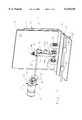
- FIG. 1is a front perspective view of one embodiment of a sheet feeding apparatus of the present invention with a tray and a cover, which are utilized to support a second source of sheets, being removed to show its pick feed mechanism.
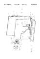
- FIG. 2is a front perspective view of the sheet feeding apparatus of FIG. 1 with the tray and a portion of the cover, which are utilized to support the second source of sheets, being shown.
- FIG. 3is a perspective view of the sheet feeding apparatus of FIG. 1 and taken from the right side of FIG. 2.
- FIG. 4is a side elevation view of the sheet feeding apparatus of FIG. 1 in which the single pick feed mechanism is feeding sheets of media from the bottom of a stack of sheets of media constituting the second source.
- FIG. 5is a side elevation view of the sheet feeding apparatus of FIG. 1, similar to FIG. 4, in which the single pick feed mechanism is feeding sheets of media from the top of a stack of sheets of media constituting the first source.
- FIG. 6is a schematic side view of another embodiment of the sheet feeding apparatus of the present invention in which the second source is designed for single sheet feeding only.
- an inclined portion 10which is substantially vertical, of a frame 11 of a laser printer 12.
- a stack 14 of sheets 15 of mediasuch as paper, for example, which constitutes a first source, is supported by the inclined portion 10 of the frame 11 and a sheet separating dam 16.
- the sheet separating dam 16is integral with the inclined portion 10 of the frame 11 and extends substantially horizontal.
- a pick feed mechanism 20which is preferably an autocompensator of the type shown and described in U.S. Pat. No. 5,527,026 to Padget et al and incorporated by reference herein, includes a pair of pick rolls 21 and 22. It should be understood that the pick feed mechanism 20 could be other than the autocompensator of the aforesaid Padget et al patent and could have only one of the pick rolls 21 and 22, if desired.
- the pick feed mechanism 20includes a housing 23 having a base 24 (see FIG. 4) and a wall 25 integral with the base 24 and extending substantially perpendicular therefrom.
- a cover 27(see FIG. 3) is removably attached to the base 24 (see FIG. 4) by having snap fasteners 28 (see FIG. 3) receive studs 29 (see FIG. 4) extending substantially perpendicular from the base 24 of the housing 23.
- a reversible electric motor 30(see FIG. 1) is supported by the frame 11 through having a mounting plate 31 attached to a side portion (not shown) of the frame 11.
- the motor 30has its shaft 32 rotate a gear 33 attached thereto.
- the gear 33is part of a gear train including gears 34, 35, and 36.
- An input shaft 37is attached to the gear 36 and is supported by a side portion (not shown) of the frame 11 between the gear 36 and the left side of the inclined portion 10 of the frame 11.
- the input shaft 37could extend to a side portion (not shown) of the frame 11 on the right side of the inclined portion 10 of the frame 11, if desired.
- the input shaft 37also is attached to a gear 40 (see FIG. 4).
- the input shaft 37extends through the gear 40 and through the housing cover 27 (see FIG. 3).
- the gear 40rotates with the input shaft 37 and is supported thereby.
- a clip(not shown) holds the input shaft 37 in the cover 27 while permitting the input shaft 37 to rotate.
- the gear 40rotates the pick rolls 21 and 22 through a gear train.
- the gear trainincludes gears 41 (see FIG. 4), 42, and 43.
- the gear 43is connected to a shaft 44 (see FIG. 1) to which the pick rolls 21 and 22 are connected.
- rotation of the gear 40 about its axis of rotationrotates the pick rolls 21 and 22.
- a fluid damper 46(see FIG. 4) is attached to the housing 23 by being secured to an extension 47 of the base 24 of the housing 23.
- the fluid damper 46includes a gear 48 meshing with the gear 40.
- the gear 48is disposed in a viscous material such as grease, for example, within the fluid damper 46.
- the housing 23is rotated clockwise, as indicated by an arrow 49, about the axis of the input shaft 37 to the position of FIG. 4 from the position of FIG. 5.
- the clockwise (as viewed in FIG. 4) rotation of the housing 23is produced by the fluid damper 46 creating a drag component on the housing 23 to induce a torque therein.
- the drag component on the housing 23can be produced by any suitable device capable of imparting a drag component or any suitable device capable of imparting a torque.
- This clockwise rotation of the housing 23moves the pick rolls 21 (see FIG. 3) and 22 through slots 50 and 51, respectively, in an inclined tray 52.
- the tray 52is supported by side portions (not shown) of the frame 11.
- An inclined cover 53(see FIG. 4), which is substantially parallel to the tray 52, is spaced from the tray 52 to receive a stack 54 of sheets 55 of media such as paper, for example, therebetween.
- the stack 54 of the sheets 55 of mediaconstitutes a second source.
- the cover 53is supported by side portions (not shown) of the frame 11.
- a flat, U-shaped spring 56has its two free ends 57 extending through two holes (not shown) in the tray 52.
- the spring 56engages the lowermost sheet 55 in the stack 54 of media and urges the uppermost sheet 55 in the stack 54 of media against an inner surface 58 of the cover 53.
- the lowermost sheet 55 of media of the stack 54is advanced from the stack 54 by the pick rolls 21 (see FIG. 1) and 22 rotating counterclockwise as indicated by an arrow 59 in FIG. 4.
- the picked bottom sheet 55 of the stack 54 of mediahas its leading edge initially engage a sheet separating dam 60 on the bottom end of the cover 53.
- the sheet separating dam 60separates the picked bottom sheet 55 of media from the remaining sheets 55 in the stack 54.
- the feed path of the picked sheet 55 of mediais indicated by a line 61.
- a curved surface 62 of a guide 63engages the leading edge of the sheet 55 and directs it between a pair of feed rolls 64 and 65.
- the guide 63is supported by side portions (not shown) of the frame 11.
- the feed rolls 64 and 65are attached to shafts 66 and 67, respectively, for rotation therewith.
- the shafts 66 and 67are rotatably supported in side portions (not shown) of the frame 11.
- One of the feed rolls 64 and 65is driven by a motor (not shown) rotating the shaft 66 or 67 to rotate both of the feed rolls 64 and 65.
- the pick rolls 21 (see FIG. 1) and 22engage the uppermost sheet 15 (see FIG. 5) of media in the stack 14.
- the pick rolls 21 (see FIG. 1) and 22are rotating clockwise, as indicated by an arrow 69 in FIG. 5 for the pick roll 22, to advance the uppermost sheet 15 of media from the stack 14.
- the uppermost sheet 15 of mediaWhen the uppermost sheet 15 of media is advanced from the stack 14, the uppermost sheet 15 has its leading edge advanced along the sheet separating dam 16 to separate the sheet 15 from the remainder of the stack 14. Then, the sheet 15 is fed along a path indicated by a line 70 in FIG. 5.
- the guide 63has a curved surface 71 disposed to guide the sheet 15 of media between the feed rolls 64 and 65. After leaving the feed rolls 64 and 65, the sheet 15 of media or the sheet 55 of media is advanced by the feed rolls 64 and 65 into a nip formed between a toner roll 72 (see FIG. 6) and a transfer roll 73.
- a cartridge 74 of the laser printer 12has toner therein for supply therefrom through the toner roll 72 for application to selected portions of the sheet 15 (see FIG. 4) or 55 of media to print thereon. This constitutes a processing station at which printing on the sheet 15 or 55 of media occurs.
- the sheet 15 or 55 of mediais fed through feed rolls 75 (see FIG. 6) and 76 of a fuser 77 at which the printed matter is fixed to the sheet 15 (see FIG. 4) or 55 of media.
- the sheet 15 or 55 of mediais fed through feed rolls 78 (see FIG. 6) and 79 and feed rolls 80 and 81 to a curved surface 82 on which the sheets 15 or 55 (see FIG. 4) of media are stacked for storage as indicated at 83 in FIG. 6. It should be understood that the feed rolls 75, 76, and 78-81 are supported and driven in the same manner as the feed rolls 64 and 65.
- FIG. 6shows only a single sheet 84 of media disposed between the tray 52 and the cover 53 rather than the sheets 55 (see FIG. 5). Because only the single sheet 84 (see FIG. 6) can be used in this embodiment, the cover 53 does not require the flat spring 56 (see FIG. 4) or the sheet separating dam 60 on the bottom end of the cover 53.
- the guide 63also is not needed. Instead, the tray 52 (see FIG. 6) has a dam surface 85 adjacent its bottom end for supporting the single sheet 84 of media and guiding the single sheet 84 of media between the feed rolls 64 and 65 and a guide surface 86 beneath the guide surface 85 for guiding each of the sheets 15 of media along the sheet separating dam 16 and away from the stack 14 to the feed rolls 64 and 65.
- the rotation of the housing 23 between its two positions in the embodiment of FIG. 6is the same as described for the embodiment of FIGS. 1-5.
- gear 40(see FIG. 4) has been shown and described as attached to the input shaft 37 for rotation therewith and support thereby, it should be understood that the gear 40 could be rotatably mounted on a fixed shaft, which would be supported by portions (not shown) of the frame 11, with the input shaft 37 have another gear attached thereto for meshing with the gear 40.
- the gears 40, 41, 42 and 43must be freely rotatable relative to the housing 23 and the housing 23 must have its axis of rotation aligned with the axis of rotation of the gear 40 in order for the housing 23 to be capable of moving between the positions of FIGS. 4 and 5.
- gear 48(see FIG. 4) has been shown and described as engaging the gear 40 to create the drag component, it should be understood that the gear 48 may engage any of the gears 41-43 of the gear train instead of the gear 40.
- each of the dam 16(see FIG. 1), the dam 60 (see FIG. 4), and the dam surface 85 (see FIG. 6) has longitudinal ribs and friction pads.
- One suitable example of such longitudinal ribs and friction pads on a damis shown and described in the copending patent application of Stephen A. Oleksa et al, Ser. No. 08/879,351, filed Jun. 20, 1997, now U.S. Pat. No. 5,895,040; for "Sheet Separator" and assigned to the same assignee as this application.
- An advantage of this inventionis that media such as paper, for example, of different sizes may be fed by a single pick feed mechanism. Another advantage of this invention is that two different sources of sheets of media may be preloaded. A further advantage of this invention is that sheets of media of different widths may be fed without having to stop operation of a printer.
Landscapes
- Engineering & Computer Science (AREA)
- Mechanical Engineering (AREA)
- Sheets, Magazines, And Separation Thereof (AREA)
Abstract
Description
Claims (5)
Priority Applications (2)
| Application Number | Priority Date | Filing Date | Title |
|---|---|---|---|
| US09/292,481US6135438A (en) | 1999-04-15 | 1999-04-15 | Apparatus for feeding sheets from two separate sources |
| GB0007528AGB2351071A (en) | 1999-04-15 | 2000-03-28 | Sheet feeding from two sources with a single pick feed mechanism |
Applications Claiming Priority (1)
| Application Number | Priority Date | Filing Date | Title |
|---|---|---|---|
| US09/292,481US6135438A (en) | 1999-04-15 | 1999-04-15 | Apparatus for feeding sheets from two separate sources |
Publications (1)
| Publication Number | Publication Date |
|---|---|
| US6135438Atrue US6135438A (en) | 2000-10-24 |
Family
ID=23124863
Family Applications (1)
| Application Number | Title | Priority Date | Filing Date |
|---|---|---|---|
| US09/292,481Expired - LifetimeUS6135438A (en) | 1999-04-15 | 1999-04-15 | Apparatus for feeding sheets from two separate sources |
Country Status (2)
| Country | Link |
|---|---|
| US (1) | US6135438A (en) |
| GB (1) | GB2351071A (en) |
Cited By (22)
| Publication number | Priority date | Publication date | Assignee | Title |
|---|---|---|---|---|
| WO2002046075A1 (en)* | 2000-12-08 | 2002-06-13 | Lexmark International, Inc. | Dual tray printer with single drive shaft and dual media picks |
| US6659444B2 (en)* | 2001-02-23 | 2003-12-09 | Canon Kabushiki Kaisha | Sheet feed apparatus, and recording apparatus having sheet feed apparatus |
| US20040094886A1 (en)* | 2002-11-18 | 2004-05-20 | Eskey Eric U. | Media handling device and methods |
| US20050073085A1 (en)* | 2003-10-02 | 2005-04-07 | Yasuaki Fukada | Hybrid paper supply module and image forming apparatus equipped with such hybrid paper supply module, and also paper supply mechanism and image forming apparatus equipped with such paper supply mechanism |
| US20060083566A1 (en)* | 2004-10-15 | 2006-04-20 | Hwang Peter G | Imaging device |
| US20060214357A1 (en)* | 2005-03-24 | 2006-09-28 | Lexmark International, Inc. | Paper feed assembly |
| US20060214353A1 (en)* | 2005-03-23 | 2006-09-28 | Lexmark International, Inc. | Integrated media input tray with manual feeder |
| US20060243932A1 (en)* | 2005-04-28 | 2006-11-02 | Canon Kabushiki Kaisha | Image reading/recording apparatus |
| US20080203650A1 (en)* | 2007-02-28 | 2008-08-28 | Brother Kogyo Kabushiki Kaisha | Sheet Supplying Devices And Image Recording Apparatuses Including The Same |
| US20090039587A1 (en)* | 2007-08-08 | 2009-02-12 | Chia-Shin Lin | Automatic Paper Feed Device |
| US20090152796A1 (en)* | 2005-03-18 | 2009-06-18 | Pitney Bowes Inc. | Multimode stack and shingle document feeder |
| US20090196653A1 (en)* | 2008-01-31 | 2009-08-06 | Kinpo Electronics, Inc. | Method for commonly using scanning/printing path of a multifunction office machine and a device thereof |
| US20100156025A1 (en)* | 2008-12-18 | 2010-06-24 | Canon Kabushiki Kaisha | Printing apparatus and printing method |
| WO2011035138A1 (en)* | 2009-09-18 | 2011-03-24 | Hid Global Corporation | Dual hopper assembly |
| US20130140756A1 (en)* | 2011-12-02 | 2013-06-06 | Lg N-Sys Inc. | Medium Storage Box, Medium Handling Apparatus and Financial Device |
| US11400680B2 (en) | 2011-11-10 | 2022-08-02 | Packsize Llc | Converting machine |
| US11446891B2 (en) | 2017-06-08 | 2022-09-20 | Packsize Llc | Tool head positioning mechanism for a converting machine, and method for positioning a plurality of tool heads in a converting machine |
| US11584608B2 (en) | 2017-01-18 | 2023-02-21 | Packsize Llc | Converting machine with fold sensing mechanism |
| US11634244B2 (en) | 2018-06-21 | 2023-04-25 | Packsize Llc | Packaging machine and systems |
| US11667096B2 (en) | 2018-04-05 | 2023-06-06 | Avercon BVBA | Packaging machine infeed, separation, and creasing mechanisms |
| US11752724B2 (en)* | 2016-06-16 | 2023-09-12 | Packsize Llc | Box forming machine |
| US11780626B2 (en) | 2018-04-05 | 2023-10-10 | Avercon BVBA | Box template folding process and mechanisms |
Citations (11)
| Publication number | Priority date | Publication date | Assignee | Title |
|---|---|---|---|---|
| JPS5847737A (en)* | 1981-09-14 | 1983-03-19 | Canon Inc | Paper feeding device |
| JPS6288737A (en)* | 1985-10-16 | 1987-04-23 | Hitachi Ltd | Paper sheet processing equipment |
| US4688782A (en)* | 1984-12-13 | 1987-08-25 | Xerox Corporation | Vertical vacuum corrugation feeder |
| JPS6317742A (en)* | 1986-07-10 | 1988-01-25 | Toshiba Corp | Reading device |
| JPS63262351A (en)* | 1987-04-17 | 1988-10-28 | Fujitsu Ltd | automatic paper feed mechanism |
| JPH03284555A (en)* | 1990-03-30 | 1991-12-16 | Nec Home Electron Ltd | Paper feed mechanism |
| JPH0455231A (en)* | 1990-06-21 | 1992-02-21 | Canon Inc | Sheet material feeding device |
| JPH04365730A (en)* | 1991-06-13 | 1992-12-17 | Tokyo Electric Co Ltd | Automatic paper feed mechanism |
| US5527026A (en)* | 1995-03-17 | 1996-06-18 | Lexmark International, Inc. | Auto compensating paper feeder |
| US5622364A (en)* | 1996-03-27 | 1997-04-22 | Lexmark International, Inc. | Apparatus and method of determining a media level in a supply tray |
| US5862446A (en)* | 1996-10-15 | 1999-01-19 | Mita Industrial Co., Ltd. | Drive switching mechanism for use in image input apparatus |
Family Cites Families (4)
| Publication number | Priority date | Publication date | Assignee | Title |
|---|---|---|---|---|
| US3756586A (en)* | 1971-12-16 | 1973-09-04 | Ibm | Selective cut sheet feed device |
| JPS5411671Y2 (en)* | 1975-10-16 | 1979-05-24 | ||
| US4222557A (en)* | 1978-05-16 | 1980-09-16 | Wang Laboratories, Inc. | Printer feeding and stacking |
| IT1291006B1 (en)* | 1997-01-13 | 1998-12-14 | Olivetti Lexikon Spa | DEVICE FOR SELECTIVELY FEEDING PAPER FROM TWO DRAWERS INTO AN OFFICE MACHINE. |
- 1999
- 1999-04-15USUS09/292,481patent/US6135438A/ennot_activeExpired - Lifetime
- 2000
- 2000-03-28GBGB0007528Apatent/GB2351071A/ennot_activeWithdrawn
Patent Citations (11)
| Publication number | Priority date | Publication date | Assignee | Title |
|---|---|---|---|---|
| JPS5847737A (en)* | 1981-09-14 | 1983-03-19 | Canon Inc | Paper feeding device |
| US4688782A (en)* | 1984-12-13 | 1987-08-25 | Xerox Corporation | Vertical vacuum corrugation feeder |
| JPS6288737A (en)* | 1985-10-16 | 1987-04-23 | Hitachi Ltd | Paper sheet processing equipment |
| JPS6317742A (en)* | 1986-07-10 | 1988-01-25 | Toshiba Corp | Reading device |
| JPS63262351A (en)* | 1987-04-17 | 1988-10-28 | Fujitsu Ltd | automatic paper feed mechanism |
| JPH03284555A (en)* | 1990-03-30 | 1991-12-16 | Nec Home Electron Ltd | Paper feed mechanism |
| JPH0455231A (en)* | 1990-06-21 | 1992-02-21 | Canon Inc | Sheet material feeding device |
| JPH04365730A (en)* | 1991-06-13 | 1992-12-17 | Tokyo Electric Co Ltd | Automatic paper feed mechanism |
| US5527026A (en)* | 1995-03-17 | 1996-06-18 | Lexmark International, Inc. | Auto compensating paper feeder |
| US5622364A (en)* | 1996-03-27 | 1997-04-22 | Lexmark International, Inc. | Apparatus and method of determining a media level in a supply tray |
| US5862446A (en)* | 1996-10-15 | 1999-01-19 | Mita Industrial Co., Ltd. | Drive switching mechanism for use in image input apparatus |
Cited By (39)
| Publication number | Priority date | Publication date | Assignee | Title |
|---|---|---|---|---|
| US6688590B2 (en)* | 2000-12-08 | 2004-02-10 | Lexmark International, Inc. | Dual tray printer with single drive shaft and dual media picks |
| WO2002046075A1 (en)* | 2000-12-08 | 2002-06-13 | Lexmark International, Inc. | Dual tray printer with single drive shaft and dual media picks |
| US6659444B2 (en)* | 2001-02-23 | 2003-12-09 | Canon Kabushiki Kaisha | Sheet feed apparatus, and recording apparatus having sheet feed apparatus |
| US20040094886A1 (en)* | 2002-11-18 | 2004-05-20 | Eskey Eric U. | Media handling device and methods |
| US7063314B2 (en)* | 2002-11-18 | 2006-06-20 | Hewlett-Packard Development Company, L.P. | Media handling device and methods |
| US7451972B2 (en)* | 2003-10-02 | 2008-11-18 | Sharp Kabushiki Kaisha | Hybrid paper supply module and image forming apparatus equipped with such hybrid paper supply module, and also paper supply mechanism and image forming apparatus equipped with such paper supply mechanism |
| US20050073085A1 (en)* | 2003-10-02 | 2005-04-07 | Yasuaki Fukada | Hybrid paper supply module and image forming apparatus equipped with such hybrid paper supply module, and also paper supply mechanism and image forming apparatus equipped with such paper supply mechanism |
| US7403739B2 (en)* | 2004-10-15 | 2008-07-22 | Hewlett-Packard Development Company, L.P. | Imaging device |
| US20060083566A1 (en)* | 2004-10-15 | 2006-04-20 | Hwang Peter G | Imaging device |
| US7699303B2 (en)* | 2005-03-18 | 2010-04-20 | Pitney Bowes Inc. | Multimode stack and shingle document feeder |
| US20090152796A1 (en)* | 2005-03-18 | 2009-06-18 | Pitney Bowes Inc. | Multimode stack and shingle document feeder |
| US20060214353A1 (en)* | 2005-03-23 | 2006-09-28 | Lexmark International, Inc. | Integrated media input tray with manual feeder |
| US20060214357A1 (en)* | 2005-03-24 | 2006-09-28 | Lexmark International, Inc. | Paper feed assembly |
| US7467790B2 (en) | 2005-03-24 | 2008-12-23 | Lexmark International, Inc. | Paper feed assembly |
| US20060243932A1 (en)* | 2005-04-28 | 2006-11-02 | Canon Kabushiki Kaisha | Image reading/recording apparatus |
| US7782504B2 (en)* | 2005-04-28 | 2010-08-24 | Canon Kabushiki Kaisha | Image reading/recording apparatus |
| US20080203650A1 (en)* | 2007-02-28 | 2008-08-28 | Brother Kogyo Kabushiki Kaisha | Sheet Supplying Devices And Image Recording Apparatuses Including The Same |
| US7980547B2 (en)* | 2007-02-28 | 2011-07-19 | Brother Kogyo Kabushiki Kaisha | Sheet supplying devices and image recording apparatuses including the same |
| US20090039587A1 (en)* | 2007-08-08 | 2009-02-12 | Chia-Shin Lin | Automatic Paper Feed Device |
| US20090196653A1 (en)* | 2008-01-31 | 2009-08-06 | Kinpo Electronics, Inc. | Method for commonly using scanning/printing path of a multifunction office machine and a device thereof |
| US8104981B2 (en)* | 2008-01-31 | 2012-01-31 | Kinpo Electronics, Inc. | Method for commonly using scanning/printing path of a multifunction office machine and a device thereof |
| US20120086162A1 (en)* | 2008-01-31 | 2012-04-12 | Kinpo Electronics, Inc. | Method for commonly using scanning/printing path of a multifunction office machine and a device thereof |
| US20100156025A1 (en)* | 2008-12-18 | 2010-06-24 | Canon Kabushiki Kaisha | Printing apparatus and printing method |
| US8382092B2 (en) | 2009-09-18 | 2013-02-26 | Hid Global Corporation | Dual hopper assembly |
| WO2011035138A1 (en)* | 2009-09-18 | 2011-03-24 | Hid Global Corporation | Dual hopper assembly |
| US11400680B2 (en) | 2011-11-10 | 2022-08-02 | Packsize Llc | Converting machine |
| US12053949B2 (en) | 2011-11-10 | 2024-08-06 | Packsize Llc | Converting machine |
| US11731385B2 (en) | 2011-11-10 | 2023-08-22 | Packsize Llc | Converting machine |
| US20130140756A1 (en)* | 2011-12-02 | 2013-06-06 | Lg N-Sys Inc. | Medium Storage Box, Medium Handling Apparatus and Financial Device |
| US9346639B2 (en)* | 2011-12-02 | 2016-05-24 | Lg Cns Co., Ltd. | Medium storage box, medium handling apparatus and financial device |
| US11752724B2 (en)* | 2016-06-16 | 2023-09-12 | Packsize Llc | Box forming machine |
| US11584608B2 (en) | 2017-01-18 | 2023-02-21 | Packsize Llc | Converting machine with fold sensing mechanism |
| US11446891B2 (en) | 2017-06-08 | 2022-09-20 | Packsize Llc | Tool head positioning mechanism for a converting machine, and method for positioning a plurality of tool heads in a converting machine |
| US11667096B2 (en) | 2018-04-05 | 2023-06-06 | Avercon BVBA | Packaging machine infeed, separation, and creasing mechanisms |
| US11780626B2 (en) | 2018-04-05 | 2023-10-10 | Avercon BVBA | Box template folding process and mechanisms |
| US12023887B2 (en) | 2018-04-05 | 2024-07-02 | Avercon BVBA | Packaging machine infeed, separation, and creasing mechanisms |
| US11878825B2 (en) | 2018-06-21 | 2024-01-23 | Packsize Llc | Packaging machine and systems |
| US11634244B2 (en) | 2018-06-21 | 2023-04-25 | Packsize Llc | Packaging machine and systems |
| US12291365B2 (en) | 2018-06-21 | 2025-05-06 | Packsize, Llc | Packaging machine and systems |
Also Published As
| Publication number | Publication date |
|---|---|
| GB0007528D0 (en) | 2000-05-17 |
| GB2351071A (en) | 2000-12-20 |
Similar Documents
| Publication | Publication Date | Title |
|---|---|---|
| US6135438A (en) | Apparatus for feeding sheets from two separate sources | |
| US4721297A (en) | Sheet feeder | |
| EP0504833B1 (en) | Sheet feeding apparatus | |
| CA1121752A (en) | Printer feeding and stacking | |
| EP0524646A1 (en) | Sheet feeding apparatus | |
| JPH0270634A (en) | Paper feeder | |
| JPS62100330A (en) | Self-function retention type feeding module | |
| JPH02502716A (en) | double sided document holder | |
| US6688590B2 (en) | Dual tray printer with single drive shaft and dual media picks | |
| US4982942A (en) | Sheet feed mechanism | |
| JPH0632439U (en) | Paper feeder | |
| US4488829A (en) | Multibin sheet feeder for use with a printer | |
| KR100467624B1 (en) | Paper aligning apparatus for duplex printer | |
| JPH0676148B2 (en) | Sheet material feeder | |
| JP2547978B2 (en) | Sheet material feeder | |
| JPH0633851U (en) | Sheet media separation and supply device | |
| JPS63315435A (en) | Double-feed preventer for sheet feeder | |
| JPH0647864Y2 (en) | Separate paper feeder | |
| JP3293985B2 (en) | Paper feeder | |
| JPH03166134A (en) | Structure of sheet feed cassette | |
| KR100449103B1 (en) | Auto Paper suppling device for printer | |
| EP1107564A2 (en) | Automated sheet delivery to selected paths using reversible crenellated roller | |
| JPH054731A (en) | Paper feeder | |
| JPH0275533A (en) | Paper feeding device | |
| JPH0444510Y2 (en) |
Legal Events
| Date | Code | Title | Description |
|---|---|---|---|
| AS | Assignment | Owner name:LEXMARK INTERNATIONAL, INC., KENTUCKY Free format text:ASSIGNMENT OF ASSIGNORS INTEREST;ASSIGNORS:NEWMAN, ROBERT G.;WILLIAMS, SCOTT S.;REEL/FRAME:009910/0960 Effective date:19990413 | |
| STCF | Information on status: patent grant | Free format text:PATENTED CASE | |
| FEPP | Fee payment procedure | Free format text:PAYOR NUMBER ASSIGNED (ORIGINAL EVENT CODE: ASPN); ENTITY STATUS OF PATENT OWNER: LARGE ENTITY | |
| FPAY | Fee payment | Year of fee payment:4 | |
| FPAY | Fee payment | Year of fee payment:8 | |
| FPAY | Fee payment | Year of fee payment:12 | |
| AS | Assignment | Owner name:CHINA CITIC BANK CORPORATION LIMITED, GUANGZHOU BR Free format text:PATENT SECURITY AGREEMENT;ASSIGNOR:LEXMARK INTERNATIONAL, INC.;REEL/FRAME:046989/0396 Effective date:20180402 | |
| AS | Assignment | Owner name:CHINA CITIC BANK CORPORATION LIMITED, GUANGZHOU BR Free format text:CORRECTIVE ASSIGNMENT TO CORRECT THE INCORRECT U.S. PATENT NUMBER PREVIOUSLY RECORDED AT REEL: 046989 FRAME: 0396. ASSIGNOR(S) HEREBY CONFIRMS THE PATENT SECURITY AGREEMENT;ASSIGNOR:LEXMARK INTERNATIONAL, INC.;REEL/FRAME:047760/0795 Effective date:20180402 | |
| AS | Assignment | Owner name:LEXMARK INTERNATIONAL, INC., KENTUCKY Free format text:RELEASE BY SECURED PARTY;ASSIGNOR:CHINA CITIC BANK CORPORATION LIMITED, GUANGZHOU BRANCH, AS COLLATERAL AGENT;REEL/FRAME:066345/0026 Effective date:20220713 |