US6135327A - Battery operated grease gun - Google Patents
Battery operated grease gunDownload PDFInfo
- Publication number
- US6135327A US6135327AUS09/164,655US16465598AUS6135327AUS 6135327 AUS6135327 AUS 6135327AUS 16465598 AUS16465598 AUS 16465598AUS 6135327 AUS6135327 AUS 6135327A
- Authority
- US
- United States
- Prior art keywords
- final driver
- housing
- plunger
- yoke
- pump mechanism
- Prior art date
- Legal status (The legal status is an assumption and is not a legal conclusion. Google has not performed a legal analysis and makes no representation as to the accuracy of the status listed.)
- Expired - Lifetime
Links
- 239000004519greaseSubstances0.000titleabstractdescription69
- 230000007246mechanismEffects0.000claimsabstractdescription43
- 230000005540biological transmissionEffects0.000claimsabstractdescription42
- 230000002093peripheral effectEffects0.000claimsdescription10
- 239000007788liquidSubstances0.000claims3
- 230000000717retained effectEffects0.000claims3
- 239000000314lubricantSubstances0.000description19
- 238000010276constructionMethods0.000description5
- 239000000969carrierSubstances0.000description2
- XAGFODPZIPBFFR-UHFFFAOYSA-NaluminiumChemical compound[Al]XAGFODPZIPBFFR-UHFFFAOYSA-N0.000description1
- 229910052782aluminiumInorganic materials0.000description1
- 230000000994depressogenic effectEffects0.000description1
- 239000003562lightweight materialSubstances0.000description1
- 238000012986modificationMethods0.000description1
- 230000004048modificationEffects0.000description1
Images


Classifications
- F—MECHANICAL ENGINEERING; LIGHTING; HEATING; WEAPONS; BLASTING
- F16—ENGINEERING ELEMENTS AND UNITS; GENERAL MEASURES FOR PRODUCING AND MAINTAINING EFFECTIVE FUNCTIONING OF MACHINES OR INSTALLATIONS; THERMAL INSULATION IN GENERAL
- F16N—LUBRICATING
- F16N3/00—Devices for supplying lubricant by manual action
- F16N3/10—Devices for supplying lubricant by manual action delivering grease
- F16N3/12—Grease guns
Definitions
- the present inventionpertains to a battery operated grease gun and in particular to a pump mechanism of the grease gun that employs a speed reducing and torque increasing transmission that rotates a final driver that is a part of the transmission, and a sliding yoke that is reciprocated by the final driver and is coupled to a plunger that dispenses the grease under pressure where the plunger is mounted to the yoke for relative movement therebetween.
- a conventional hand operated grease gunis basically comprised of a housing containing a pump mechanism comprised of a plunger that reciprocates in a tubular pump chamber, a check valve and discharge spout that communicate with the pump chamber, a grease reservoir that communicate with the pump chamber tube and is adapted to have a tubular body containing grease or a grease reservoir attached thereto, and a manually manipulated pump lever or handle that is pivotally connected to the housing and is connected to the pump plunger to reciprocate the plunger in the pump chamber on manual pivoting movement of the lever.
- the rate at which the lever is manually pivoteddetermines the rate at which grease is dispensed through the discharge spout.
- the manual force exerted on the lever multiplied by the length of the lever used as leveragedetermines the force or pressure of the grease dispensed from the gun through the discharge spout.
- the forces directed off line with the line of plunger reciprocationcan have a tendency to cause the plunger to bind or catch in the pump chamber as the plunger reciprocates. This can affect the dispensing performance of the battery operated grease gun and can lead to wear of the plunger and pump chamber wall which could lead to the complete inability of the battery operated grease gun to dispense grease under pressure.
- a battery operated grease gun having a compact power transmission design that also eliminates the potential of the plunger binding or catching in the pump chamber as it reciprocateswould overcome the disadvantages experienced in many prior art battery operated grease gun designs.
- the battery operated grease gun of the present inventionhas a compact housing that encloses an electric motor, a power transmission, a pump plunger reciprocating in a pump chamber communicating with a grease reservoir and a discharge spout, a final driver driven by the power transmission, a yoke driven by the final driver and operatively connected with the reciprocating plunger, and a battery compartment in a handle of the grease gun housing.
- the power transmissionis a speed reducing planetary gearing transmission that increases the torque output of the electric motor and drives the final driver in rotation.
- the final driverhas a drive pin on one side that engages the yoke and transforms the rotation of the final driver to reciprocating movement of the yoke and plunger.
- a series of planet gearsare mounted on the opposite side of the final driver from the drive pin.
- the planet gearsengage with an orbit gear and sun gear of the power transmission. This construction of the final driver contributes to the compactness of the grease gun design.
- the yokereciprocates the plunger through a sliding connection between the yoke and a head of the plunger.
- This connectionenables the plunger head to move relative to the yoke along a line of movement that is transverse to the line of reciprocating movement of the plunger.
- the connection between the yoke and plungerreduces the potential for the plunger to bind or catch in the pump chamber as it is reciprocated by the yoke.
- the manual handle containing the battery compartmentis positioned on one side of the final driver, the yoke and plunger, and the battery operated motor and power transmission are positioned on the opposite side of the final driver, yoke and plunger.
- FIG. 1is a side elevation view, in section, of the battery operated grease gun of the present invention
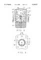
- FIG. 2is a partial front elevation view of the yoke and plunger of the grease gun taken along the line 2--2 of FIG. 1;
- FIG. 3is a partial rear elevation view of the final driver taken along the line 3--3 of FIG. 1;
- FIG. 4is a view of the drive surface of the final driver removed from the grease gun
- FIG. 5is a view of the driven surface of the final driver removed from the grease gun
- FIG. 6is a cross-section of the final driver taken along the ling 6--6 of FIG. 4;
- FIG. 7is a perspective view of the final driver showing its driven surface with planet gears attached and showing the drive pin projecting from its drive surface;
- FIG. 8is a side elevation view of the yoke and plunger removed from the grease gun.
- FIG. 9is a bottom view of the yoke and plunger shown in FIG. 8.
- the battery operated grease gun 10 of the present inventionis shown in FIG. 1.
- the grease gun 10basically comprises an electric motor 12 that drives a power transmission 14 that in turn drives a pump mechanism 16 that discharges grease under pressure through a discharge spout 18. These component parts are contained in or mounted on a housing 20.
- the housing 20 in the preferred embodimentis constructed of plastic as is typical in many prior art battery operated grease guns.
- the housing 20is constructed of several housing parts that are held together by fasteners (not shown), as also is conventional.
- the housingis constructed with a motor and transmission compartment 22 on one side and a manual handle 24 on an opposite side.
- the handle 24is basically hollow and can be dimensioned to accommodate one or more batteries (not shown) in its interior.
- the bottom edge 26 of the handlecan be designed for the attachment of a separate battery compartment represented by dashed lines in FIG. 1.
- a trigger 28is mounted on the handle 24 in a position where it can be easily manipulated by the index finger of a hand gripping the handle.
- the trigger 28is connected to an electric switch 29 that is selectively operated by manual manipulation of the trigger to provide electric power from the batteries to the electric motor 12 to operate the motor.
- the selective operation of the electric motor 12 in this manneris well known in the prior art.
- the positioning of the handle 24 containing the batteries or having a battery compartment attached thereto and the positioning of the electric motor 12 and power transmission 14 on opposite sides of the pump mechanism 16provides a distribution of the weight of the grease gun that enables the grease gun to be more easily manually manipulated while gripping the handle 24.
- the electric motor 12is mounted in the motor and transmission compartment 22 of the housing 20 adjacent the power transmission 14 mounted in the compartment.
- the motor 12has an output shaft with a spur gear 30 mounted thereon.
- the output shaft and spur gear 30extend through an end wall 32 of a gear casing 34 of the power transmission 14.
- the power transmission 14 contained in the gear casing 34is a three stage planetary gearing reduction transmission. It is not necessary that the transmission have three stages of planetary gearing. Any number of planetary gear stages could be made to work depending upon the motor construction.
- the output spur gear 30 of the electric motor 12also functions as a sun gear of a first planetary gear set of the power transmission 14.
- This spur gear 30drives three planet gears 36 (only one of which is seen in FIG. 1) of a first carrier 38 of the first planetary gear set.
- the planet gears 36also mesh with a first orbit gear 40 that is fixed to the gear casing 34 of the power transmission. Rotation of the output spur gear 30 of the electric motor causes the first carrier 38 to rotate at a reduced speed while increasing the torque of the motor output.
- a second sun gear 42is fixed to the first carrier 38.
- This second sun gear 42drives three planet gears (only one of which is shown in FIG. 1) of a second planetary gear set of the power transmission 14.
- the second series of planet gears 44are mounted on a second carrier 46 and also mesh with the fixed orbit gear 40 of the first planetary gear set. This second planetary gear set further reduces the speed of rotation of the electric motor output and further increases its torque.
- a third sun gear 48is fixed to the second planet gear carrier 46.
- This third sun gear 48meshes with three planet gears 50 of a third planetary gear set of the power transmission 14.
- the third set of planet gears 50mesh with a second orbit gear 52 that is fixed to the gear casing 34 of the power transmission 14.
- the third set of planet gears 50are mounted for rotation on a final driver 54.
- This third planetary gearing arrangementfurther reduces the output speed of the electric motor 12 while increasing its torque.
- the planetary gearing arrangements of the power transmission 14transform the output of the electric motor 12 reducing its speed while increasing its torque as it is transmitted to the final driver 54 causing rotation of the final driver.
- FIGS. 4-7show the final driver with its component parts removed and FIG. 7 shows the final driver including its component parts.
- the final driver 54has a circular drive surface 56 shown in FIG. 4 and a circular driven surface 58 shown in FIG. 5.
- the final driverhas a cylindrical peripheral surface 60 that spaces the drive 56 and driven 58 surfaces.
- the driven surface 56has a raised annular shoulder 61 centered on the surface.
- Three shaft holes 62extend into the annular shoulder 61 and are spacially arranged around the center of the driven surface.
- Three shafts 64are inserted into the shaft holes 62 and the planet gears 50 of the third gear set are mounted on the shafts for rotation as shown in FIG. 7.
- a driven pin hole 66 with internal screw threadingextends into the drive surface 56 of the final driver.
- a drive pin 68 with a cylindrical bushing 70 mounted for rotation thereonis screw threaded into the internal hole 66 in the final drive drive surface 56.
- the drive pin 68 and its bushing 70are shown in FIGS. 1 and 7.
- the gear casing 34 of the power transmission 14has an annular collar 72 and the final driver 54 is mounted for rotation in the annular collar.
- the annular collar 72has a cylindrical interior surface 76 that is radially spaced from the cylindrical peripheral surface 60 of the final driver.
- a roller bearing assembly 78Positioned between the cylindrical peripheral surface 60 of the final driver and the cylindrical interior surface 76 of the annular collar is a roller bearing assembly 78 that mounts the final driver 54 for rotation in the annular collar 72.
- the rotationis transmitted through the power transmission 14 to the final driver 54 and rotates the final driver in the annular collar 72 at a reduced speed of rotation from that of the motor output spur gear 30 and at an increased torque.
- the rotation of the final driver 54is transmitted by the drive pin 68 and drive pin bushing 70 to a yoke 80 and plunger 82 of the pump mechanism 16.
- the final driver 54functions as a carrier of the power transmission 14 in the same manner as the first 38 and second 46 planet gear carriers of the transmission, its axial width is substantially enlarged compared to that of the carriers. This can be seen in FIGS. 1 and 7. This increased axial width of the final driver 54 stabilizes it in the annular collar 72 and resists any tilting or skewing of the final driver 54 relative to its center axis due to forces exerted by the yoke 80 against the drive pin 68 during rotation of the final driver.
- the three planet gears 50 mounted on the final driver 54also handle thrust forces from the drive mechanism.
- the three planet gears 50 meshing with the second orbit gear 52hold the final driver 54 in its orientation with its center axis of rotation located co-axially with the axes of rotation of the transmission sun gears 30, 42, 48 and the motor output shaft, and resist any tendency of the final driver 54 to be titled or skewed from the overhung load of the forces exerted on the drive pin 68 by the yoke 80.
- Thisenables the final driver 54 to exert a substantial force on the yoke 80 which enables the yoke 80 to drive the plunger 82 to discharge grease from the grease gun at a substantial pressure as will be explained.
- the yoke 80has a generally square configuration with opposite pairs of side sliding surfaces 84, 86 spaced from each other by depressed surfaces 88, 90, respectively, a bottom surface 92 and a top surface 94. Opposite face surfaces 96, 98 of the yoke are planar and parallel to each other as shown in FIG. 9.
- An oblong cam slot 100passes through the yoke between the opposite face surfaces 96, 98.
- the cam slot 100is dimensioned to receive the drive pin 68 and its bushing 70 therein allowing sufficient room to enable the drive pin and bushing to slide through the cam slot freely from end to end.
- a transverse T-shaped slot 102passes through the yoke bottom surface 92 between its opposite face surfaces 96, 98. This transverse slot 102 functions as a plunger head slot as will be explained.
- the yoke 80is mounted in a slide box 104 that is attached to the annular collar 72 of the gear casing and is partially contained in the grease gun housing 20.
- the slide box 104is shown in FIGS. 1 and 2 and is preferably constructed of die cast aluminum but may be constructed of other similar light weight materials.
- the slide box 104has a generally square exterior configuration and contains a generally square hollow interior volume defined by a bottom wall 106, opposite side walls 108, 110, a top wall 112 and a back wall 114. As seen in FIG.
- the opposite side walls 108, 110are spaced from each other a distance that allows the yoke 80 to be positioned between the side walls with the side sliding surfaces 84, 86 of the yoke in sliding engagement with the respective opposite side walls 108, 110 of the slide box.
- This relationship between the engaging surfacesenables the yoke 80 to reciprocate through the slide box interior while substantially maintaining its orientation relative to the slide box interior shown in FIG. 2.
- a pair of sliding rails 116, 118are provided on the back wall 114 of the slide box and the yoke 80 slides across these rails as it reciprocates through the interior of the slide box.
- the dimensioning of the slide box interior walls 108, 110 and rails 116, 118permits limited movement of the yoke 80 from right to left and forward and backward in the slide box as it is reciprocated by the final driver 54. This limited amount of movement of the yoke 80 relative to the slide box compensates for any inaccuracies in the assembly of the slide box to the annular collar 72 of the gear casing.
- a notch 120is formed in the bottom wall 116 of the slide box to accommodate the plunger 82 as shown in FIGS. 1 and 2.
- the pump mechanism 16includes a pump housing 122 that, in the embodiment shown in the drawings is an integral extension of the annular collar 72 of the gear casing.
- the pump housing 122contains a cylindrical pump chamber 124 that is dimensioned to receive the plunger 82 in sliding engagement therein. As seen in FIGS. 1 and 2, the pump chamber 124 aligns with the notch 120 in the slide box bottom wall 106. This enables the plunger 82 positioned in the pump chamber 124 to extend upwardly through the notch 120 to its connection with the yoke 80 shown in FIGS. 1 and 2.
- a resilient seal 126is positioned in an annular recess in the pump housing 122 and surrounds the plunger 82. The seal 126 seals the pump chamber 124 from the slide box notch 120.
- the pump chamber 124also communicates with a lubricant supply passage 128.
- the lubricant supply passage 128communicates with the interior of a cylindrical skirt 130 of the pump housing.
- the cylindrical skirt 130has internal screw threading that is adapted to receive external screw threading on a cylindrical lubricant reservoir 131 of the type that is typically employed with grease guns.
- the lubricant supply reservoir 131contains either a supply of lubricant drawn therein or a cartridge of lubricant and has a spring biased plunger that exerts a pressure on the lubricant contained in the reservoir. The pressure exerted by the plunger provides a continuous supply of lubricant to the supply passage 128.
- the operation of the cylindrical lubricant reservoiris typical of prior art grease guns that are both manually and battery operated and therefore the reservoir is not shown in the drawing figures.
- a ball check valve assembly 132is positioned in the bottom of the pump housing 122 communicating with the pump chamber 124 and is held in place by a screw threaded plug 134.
- the chamber of the pump housing containing the ball valve 132also communicates with the discharge spout 18 of the grease gun.
- the positioning of the ball check valve 132 and the discharge spout 18 shown in FIG. 1is common to many prior art grease guns.
- lubricant supplied to the pump chamber through the supply passage 128is put under pressure. With increased pressure of the lubricant, the ball valve 132 unseats and enables the lubricant under pressure to pass through the ball valve chamber to the discharge spout 18. This operation is typical in many prior art grease guns.
- the plunger 82 of the grease gunis shown removed from the grease gun and connected to the yoke 80 in FIG. 8.
- the plunger 82has a cylindrical shank 136 that is sized to fit into the cylindrical pump chamber 124 so that the exterior surface of the shank 136 engages in sliding engagement with the interior surface of the pump chamber 124.
- the plungerhas a bottom piston surface 138 and has a circular head 140 at its opposite end.
- the circular head 140is connected to the shank portion 136 of the plunger by a necked down portion 142 of the plunger. As seen in FIGS. 1, 2 and 8, the circular head 140 of the plunger is dimensioned to be received in the T-slot 102 in the bottom surface of the yoke 80.
- the dimensions of the plunger head 140 and its necked down portion 142enable the plunger head and necked down portion to slide freely through the T-slot 102 of the yoke.
- the T-slot 102is dimensioned slightly larger than the plunger head 140 and plunger necked down portion 142 so that there is a gap or small spacing between the plunger head 140 and necked down portion 142 and the interior surface of the slot 102.
- a cylindrical reservoir filled with lubricantis first connected to the cylindrical skirt 130 of the pump housing 122.
- the cylindrical reservoirsupplies lubricant to the lubricant supply passage 128 of the pump housing.
- the user of the grease gunthen grips the handle 24 and manually manipulates the trigger switch 28 to activate the electric motor 12.
- the rotation of the motor output spur gear 30is transmitted through the power transmission 14 to cause the final driver 54 to rotate within the roller bearing assembly 78 and the annular collar 72 of the gear casing.
- the rotation of the final driver 54is transmitted to the yoke 80 by the drive pin 68 and its bushing 70 which extend into the cam slot 100 of the yoke. As the final driver 54 rotates, it causes the yoke 80 to slide in reciprocating movement inside the slide box 104.
- the sliding reciprocating movement of the yokeis transmitted to the plunger 82 causing it to reciprocate through the pump chamber 124.
- the reciprocation of the plunger 82causes its bottom piston surface 138 to be retracted beyond the lubricant supply passage 124 enabling lubricant to enter into the pump chamber 124.
- the lubricantis pushed through the pump chamber 124 and is put under pressure. The pressure of the lubricant increases until it unseats the ball check valve 132 and is then discharged through the spout 18.
- the final driver 54is employed as part of the power transmission 14 in that it functions as a carrier for the third planet gears 50, and also functions as a portion of the pump mechanism in that it drives the yoke 80, a compact construction of the battery operated grease gun is achieved.
Landscapes
- Engineering & Computer Science (AREA)
- General Engineering & Computer Science (AREA)
- Mechanical Engineering (AREA)
- Reciprocating Pumps (AREA)
Abstract
Description
Claims (27)
Priority Applications (1)
| Application Number | Priority Date | Filing Date | Title |
|---|---|---|---|
| US09/164,655US6135327A (en) | 1998-10-01 | 1998-10-01 | Battery operated grease gun |
Applications Claiming Priority (1)
| Application Number | Priority Date | Filing Date | Title |
|---|---|---|---|
| US09/164,655US6135327A (en) | 1998-10-01 | 1998-10-01 | Battery operated grease gun |
Publications (1)
| Publication Number | Publication Date |
|---|---|
| US6135327Atrue US6135327A (en) | 2000-10-24 |
Family
ID=22595479
Family Applications (1)
| Application Number | Title | Priority Date | Filing Date |
|---|---|---|---|
| US09/164,655Expired - LifetimeUS6135327A (en) | 1998-10-01 | 1998-10-01 | Battery operated grease gun |
Country Status (1)
| Country | Link |
|---|---|
| US (1) | US6135327A (en) |
Cited By (34)
| Publication number | Priority date | Publication date | Assignee | Title |
|---|---|---|---|---|
| US6315164B1 (en)* | 1998-11-11 | 2001-11-13 | Ernst Muhlbauer Kg | Method and device for generating a multi-component compound, in particular for dental purposes |
| US20040084482A1 (en)* | 2002-11-04 | 2004-05-06 | Sumner William P. | Fluid dispensing apparatus |
| US20040226969A1 (en)* | 2003-05-15 | 2004-11-18 | Shew Jerry D. | Grease gun |
| GB2402183A (en)* | 2003-05-22 | 2004-12-01 | Techway Ind Co Ltd | A battery-operated grease gun with an electronic pressure regulator |
| US20050249616A1 (en)* | 2004-05-06 | 2005-11-10 | San-I Huang | Cam-driven pump mechanism for a battery-powered grease gun |
| US20050258005A1 (en)* | 2004-05-20 | 2005-11-24 | Shang-Hsien Chen | Lubricant gun |
| US20050284892A1 (en)* | 2004-06-24 | 2005-12-29 | Weems Industries, Inc., D/B/A Legacy Manufacturing Company | Grease gun with overpressure relief valve and indicator |
| US20060070812A1 (en)* | 2004-09-24 | 2006-04-06 | Eggleton Jerry W | Battery-operated grease gun |
| US20060091159A1 (en)* | 2004-10-28 | 2006-05-04 | Shew Jerry D | Grease gun |
| US20060091161A1 (en)* | 2004-11-03 | 2006-05-04 | Jianli Cen | Portable electric grease gun |
| US20060108180A1 (en)* | 2004-11-24 | 2006-05-25 | Lincoln Industrial Corporation | Grease gun |
| US7063240B1 (en)* | 2003-08-04 | 2006-06-20 | Niswonger John O H | Powered caulking gun |
| US20060210409A1 (en)* | 2005-03-15 | 2006-09-21 | Sumner William P | Grease pump |
| US20060278660A1 (en)* | 2005-06-08 | 2006-12-14 | Ling Zhang | Automotive grease gun |
| US20070137942A1 (en)* | 2004-06-24 | 2007-06-21 | Weems R M | Battery powered grease gun with strain gauge based pressure transducer |
| CH696554A5 (en)* | 2003-10-16 | 2007-07-31 | Abnox Ag | Electrical lubricant press for lubrication with one-hand operation has gearwheel pump driven by electric motor with discrete or continuous revolution rate adjustment, e.g. conventional drill motor |
| US20080017452A1 (en)* | 2006-07-05 | 2008-01-24 | Li-Chi Chen | Lubricant gun |
| GB2462277A (en)* | 2008-07-31 | 2010-02-03 | Wen-I Guo | Grease gun used by cooperating with a rotary tool |
| US20100025435A1 (en)* | 2008-07-30 | 2010-02-04 | Guo Wen-I | Grease Gun Used by Cooperating with a Rotary Tool |
| US20100098557A1 (en)* | 2008-10-20 | 2010-04-22 | Lincoln Industrial Corporation | Hand Operated Pump |
| US7828119B1 (en) | 2006-01-13 | 2010-11-09 | Schirado Richard M | Grease gun applicator system |
| USD628677S1 (en) | 2008-10-20 | 2010-12-07 | Lincoln Industrial Corporation | Hand pump |
| US20110278326A1 (en)* | 2010-05-14 | 2011-11-17 | Guo Wen-I | Grease Gun with a Pressure-Relief Device |
| CN102720940A (en)* | 2012-06-05 | 2012-10-10 | 余姚市铭通金属制品厂 | Direct-current electric grease gun |
| WO2013023152A1 (en)* | 2011-08-10 | 2013-02-14 | Milwaukee Electric Tool Corporation | Grease gun |
| US20130081903A1 (en)* | 2011-09-29 | 2013-04-04 | Lincoln Industrial Corporation | Battery powered, handheld lubrication gun with display |
| US20130341360A1 (en)* | 2012-06-26 | 2013-12-26 | Michael C. Ryan | Grease gun |
| EP2843289A1 (en) | 2013-08-27 | 2015-03-04 | Black & Decker Inc. | Grease gun |
| WO2017124070A1 (en)* | 2016-01-15 | 2017-07-20 | Gree-See Technology, Llc | Grease gun cartridge construction |
| US10400952B1 (en) | 2014-10-21 | 2019-09-03 | Gree-See Technology, Llc | Fluid dispenser |
| US10711944B2 (en) | 2016-01-15 | 2020-07-14 | Gree-See Technology, Llc | Grease gun cartridge construction |
| USD953827S1 (en)* | 2020-08-29 | 2022-06-07 | Zhejiang Prulde Electric Appliance Co., Ltd. | Grease gun |
| USD1025728S1 (en)* | 2023-08-29 | 2024-05-07 | Yongkang Lava Star Industry and Trade Co., Ltd. | Electric grease gun |
| USD1080336S1 (en)* | 2024-10-22 | 2025-06-24 | Huili LIN | Electric grease gun |
Citations (26)
| Publication number | Priority date | Publication date | Assignee | Title |
|---|---|---|---|---|
| US3987869A (en)* | 1975-08-14 | 1976-10-26 | George Keith Bowers | Back pack lubrication system |
| US3993250A (en)* | 1975-05-19 | 1976-11-23 | Shure Alan H | Apparatus for spraying liquid materials |
| US4030665A (en)* | 1974-05-20 | 1977-06-21 | Goldwell Gmbh | Apparatus for foaming liquid cosmetic substances |
| US4114781A (en)* | 1977-06-06 | 1978-09-19 | Doyel John S | Hand-held, battery-operated decorative extruder for cookie dough and similar food substances |
| US4160525A (en)* | 1976-11-27 | 1979-07-10 | Firma Josef Wagner Gmbh | Spray gun construction |
| US4162037A (en)* | 1977-05-20 | 1979-07-24 | Masaya Koyama | Automatic sprayer |
| US4171072A (en)* | 1978-02-08 | 1979-10-16 | Geo B. Davis, Jr. | Hand held electric caulking gun |
| US4257540A (en)* | 1978-10-26 | 1981-03-24 | Mcneil Corporation | Hand-held battery-powered grease gun |
| US4273269A (en)* | 1978-02-08 | 1981-06-16 | Davis George B Jun | Hand held electric caulking gun |
| US4653675A (en)* | 1984-08-25 | 1987-03-31 | Hilti Aktiengesellschaft | Hand-held motor-driven extruding device for dispensing a plastic substance |
| US4706848A (en)* | 1986-10-06 | 1987-11-17 | Andrade Bruce M D | High efficiency battery operated water gun |
| US5150841A (en)* | 1989-09-11 | 1992-09-29 | Dowbrands Inc. | Liquid spray dispenser |
| US5188259A (en)* | 1991-02-01 | 1993-02-23 | Petit Jeffrey D | Caulking gun with belt worn cartridge |
| US5203476A (en)* | 1990-06-22 | 1993-04-20 | Keller Wilhelm A | Electrically operated dispensing appliance including mechanical means for preventing afterflow of the dispensed product |
| US5257913A (en)* | 1990-04-17 | 1993-11-02 | Schwarzer Prazision Jurgen Schwarzer Gmbh & Co. Kg | Hand tool for producing local over or under pressure |
| US5271528A (en)* | 1992-10-12 | 1993-12-21 | Hornche Trading Co., Ltd. | Automatic grease dispenser |
| US5353971A (en)* | 1993-05-10 | 1994-10-11 | Bijan Vaziri | Electric caulking gun apparatus |
| US5404967A (en)* | 1993-05-14 | 1995-04-11 | Barry; Hubert M. | Extruding device |
| US5503307A (en)* | 1995-03-08 | 1996-04-02 | Wilson; Steven J. | Quick release automatic electric caulking gun |
| US5556009A (en)* | 1994-07-18 | 1996-09-17 | Wagner Spray Tech Corporation | Adjustable constant pressure caulk gun |
| US5590816A (en)* | 1994-12-21 | 1997-01-07 | Sealed Air Corporation | Hand held dispenser for foamable compositions and dispensing system |
| US5609274A (en)* | 1995-01-28 | 1997-03-11 | Yung-Feng Chiang | Grease dispensing device |
| US5685462A (en)* | 1996-01-16 | 1997-11-11 | Power B International Inc. | Extruding apparatus with improved drive system |
| US5716007A (en)* | 1995-12-29 | 1998-02-10 | Nottingham-Spirk Design Associates, Inc. | Battery operated fluid dispenser |
| US5732794A (en)* | 1994-09-30 | 1998-03-31 | Orlitzky; Anton T. | Auger-driven automatic lubricator |
| US5775539A (en)* | 1995-05-05 | 1998-07-07 | Bates; Darryle E. | Electrically operated material dispensing gun and method |
- 1998
- 1998-10-01USUS09/164,655patent/US6135327A/ennot_activeExpired - Lifetime
Patent Citations (27)
| Publication number | Priority date | Publication date | Assignee | Title |
|---|---|---|---|---|
| US4030665A (en)* | 1974-05-20 | 1977-06-21 | Goldwell Gmbh | Apparatus for foaming liquid cosmetic substances |
| US3993250A (en)* | 1975-05-19 | 1976-11-23 | Shure Alan H | Apparatus for spraying liquid materials |
| US3987869A (en)* | 1975-08-14 | 1976-10-26 | George Keith Bowers | Back pack lubrication system |
| US4160525A (en)* | 1976-11-27 | 1979-07-10 | Firma Josef Wagner Gmbh | Spray gun construction |
| US4162037A (en)* | 1977-05-20 | 1979-07-24 | Masaya Koyama | Automatic sprayer |
| US4114781A (en)* | 1977-06-06 | 1978-09-19 | Doyel John S | Hand-held, battery-operated decorative extruder for cookie dough and similar food substances |
| US4171072A (en)* | 1978-02-08 | 1979-10-16 | Geo B. Davis, Jr. | Hand held electric caulking gun |
| US4273269A (en)* | 1978-02-08 | 1981-06-16 | Davis George B Jun | Hand held electric caulking gun |
| US4257540A (en)* | 1978-10-26 | 1981-03-24 | Mcneil Corporation | Hand-held battery-powered grease gun |
| US4653675A (en)* | 1984-08-25 | 1987-03-31 | Hilti Aktiengesellschaft | Hand-held motor-driven extruding device for dispensing a plastic substance |
| US4706848A (en)* | 1986-10-06 | 1987-11-17 | Andrade Bruce M D | High efficiency battery operated water gun |
| US5150841A (en)* | 1989-09-11 | 1992-09-29 | Dowbrands Inc. | Liquid spray dispenser |
| US5257913A (en)* | 1990-04-17 | 1993-11-02 | Schwarzer Prazision Jurgen Schwarzer Gmbh & Co. Kg | Hand tool for producing local over or under pressure |
| US5203476A (en)* | 1990-06-22 | 1993-04-20 | Keller Wilhelm A | Electrically operated dispensing appliance including mechanical means for preventing afterflow of the dispensed product |
| US5188259A (en)* | 1991-02-01 | 1993-02-23 | Petit Jeffrey D | Caulking gun with belt worn cartridge |
| US5271528A (en)* | 1992-10-12 | 1993-12-21 | Hornche Trading Co., Ltd. | Automatic grease dispenser |
| US5353971A (en)* | 1993-05-10 | 1994-10-11 | Bijan Vaziri | Electric caulking gun apparatus |
| US5404967A (en)* | 1993-05-14 | 1995-04-11 | Barry; Hubert M. | Extruding device |
| US5556009A (en)* | 1994-07-18 | 1996-09-17 | Wagner Spray Tech Corporation | Adjustable constant pressure caulk gun |
| US5732794A (en)* | 1994-09-30 | 1998-03-31 | Orlitzky; Anton T. | Auger-driven automatic lubricator |
| US5590816A (en)* | 1994-12-21 | 1997-01-07 | Sealed Air Corporation | Hand held dispenser for foamable compositions and dispensing system |
| US5709317A (en)* | 1994-12-21 | 1998-01-20 | Sealed Air Corporation | Hand held dispenser for foamable compositions and dispensing system |
| US5609274A (en)* | 1995-01-28 | 1997-03-11 | Yung-Feng Chiang | Grease dispensing device |
| US5503307A (en)* | 1995-03-08 | 1996-04-02 | Wilson; Steven J. | Quick release automatic electric caulking gun |
| US5775539A (en)* | 1995-05-05 | 1998-07-07 | Bates; Darryle E. | Electrically operated material dispensing gun and method |
| US5716007A (en)* | 1995-12-29 | 1998-02-10 | Nottingham-Spirk Design Associates, Inc. | Battery operated fluid dispenser |
| US5685462A (en)* | 1996-01-16 | 1997-11-11 | Power B International Inc. | Extruding apparatus with improved drive system |
Cited By (60)
| Publication number | Priority date | Publication date | Assignee | Title |
|---|---|---|---|---|
| US6315164B1 (en)* | 1998-11-11 | 2001-11-13 | Ernst Muhlbauer Kg | Method and device for generating a multi-component compound, in particular for dental purposes |
| US20040084482A1 (en)* | 2002-11-04 | 2004-05-06 | Sumner William P. | Fluid dispensing apparatus |
| EP2202443A1 (en)* | 2003-05-15 | 2010-06-30 | Alemite LLC | Grease gun |
| US7997456B2 (en) | 2003-05-15 | 2011-08-16 | Alemite, Llc | Grease gun |
| WO2004103058A3 (en)* | 2003-05-15 | 2007-01-11 | Alemite Llc | Grease gun |
| CN1965180B (en)* | 2003-05-15 | 2013-03-13 | 阿利米特有限公司 | Grease gun |
| US7004357B2 (en) | 2003-05-15 | 2006-02-28 | Alemite, Llc | Grease gun |
| US20040226969A1 (en)* | 2003-05-15 | 2004-11-18 | Shew Jerry D. | Grease gun |
| US20060088410A1 (en)* | 2003-05-15 | 2006-04-27 | Alemite Llc | Grease gun |
| US20090184138A1 (en)* | 2003-05-15 | 2009-07-23 | Jerry D Shew | Grease gun |
| US7523843B2 (en) | 2003-05-15 | 2009-04-28 | Alemite, Llc | Grease gun |
| AU2004241086B2 (en)* | 2003-05-15 | 2007-04-26 | Alemite Llc | Grease gun |
| GB2402183A (en)* | 2003-05-22 | 2004-12-01 | Techway Ind Co Ltd | A battery-operated grease gun with an electronic pressure regulator |
| GB2402183B (en)* | 2003-05-22 | 2005-10-12 | Techway Ind Co Ltd | A battery-operated grease gun with an electronic pressure regulator for controlling pressure of the grease |
| US7063240B1 (en)* | 2003-08-04 | 2006-06-20 | Niswonger John O H | Powered caulking gun |
| CH696554A5 (en)* | 2003-10-16 | 2007-07-31 | Abnox Ag | Electrical lubricant press for lubrication with one-hand operation has gearwheel pump driven by electric motor with discrete or continuous revolution rate adjustment, e.g. conventional drill motor |
| US20050249616A1 (en)* | 2004-05-06 | 2005-11-10 | San-I Huang | Cam-driven pump mechanism for a battery-powered grease gun |
| US7392882B2 (en) | 2004-05-20 | 2008-07-01 | Techway Industrial Co., Ltd. | Lubricant gun |
| US20050258005A1 (en)* | 2004-05-20 | 2005-11-24 | Shang-Hsien Chen | Lubricant gun |
| US20050284892A1 (en)* | 2004-06-24 | 2005-12-29 | Weems Industries, Inc., D/B/A Legacy Manufacturing Company | Grease gun with overpressure relief valve and indicator |
| US20070137942A1 (en)* | 2004-06-24 | 2007-06-21 | Weems R M | Battery powered grease gun with strain gauge based pressure transducer |
| US20060070812A1 (en)* | 2004-09-24 | 2006-04-06 | Eggleton Jerry W | Battery-operated grease gun |
| AU2005302568B2 (en)* | 2004-10-28 | 2011-02-03 | Alemite, Llc | Grease gun |
| WO2006050016A1 (en)* | 2004-10-28 | 2006-05-11 | Alemite, Llc | Grease gun |
| US7249695B2 (en)* | 2004-10-28 | 2007-07-31 | Alemite, Llc | Grease gun |
| US20060091159A1 (en)* | 2004-10-28 | 2006-05-04 | Shew Jerry D | Grease gun |
| US20060091161A1 (en)* | 2004-11-03 | 2006-05-04 | Jianli Cen | Portable electric grease gun |
| US7267198B2 (en)* | 2004-11-03 | 2007-09-11 | Jianli Cen | Portable electric grease gun |
| EP1666786A1 (en)* | 2004-11-24 | 2006-06-07 | Lincoln Industrial Corporation | Grease Gun |
| US20060108180A1 (en)* | 2004-11-24 | 2006-05-25 | Lincoln Industrial Corporation | Grease gun |
| US20060210409A1 (en)* | 2005-03-15 | 2006-09-21 | Sumner William P | Grease pump |
| US20060278660A1 (en)* | 2005-06-08 | 2006-12-14 | Ling Zhang | Automotive grease gun |
| US7828119B1 (en) | 2006-01-13 | 2010-11-09 | Schirado Richard M | Grease gun applicator system |
| US20080017452A1 (en)* | 2006-07-05 | 2008-01-24 | Li-Chi Chen | Lubricant gun |
| US20100025435A1 (en)* | 2008-07-30 | 2010-02-04 | Guo Wen-I | Grease Gun Used by Cooperating with a Rotary Tool |
| GB2462277A (en)* | 2008-07-31 | 2010-02-03 | Wen-I Guo | Grease gun used by cooperating with a rotary tool |
| US8052402B2 (en) | 2008-10-20 | 2011-11-08 | Lincoln Industrial Corporation | Hand operated pump |
| US20100098557A1 (en)* | 2008-10-20 | 2010-04-22 | Lincoln Industrial Corporation | Hand Operated Pump |
| USD628677S1 (en) | 2008-10-20 | 2010-12-07 | Lincoln Industrial Corporation | Hand pump |
| US20110278326A1 (en)* | 2010-05-14 | 2011-11-17 | Guo Wen-I | Grease Gun with a Pressure-Relief Device |
| US8783522B2 (en) | 2011-08-10 | 2014-07-22 | Milwaukee Electric Tool Corporation | Grease gun including a purge assembly |
| US9316352B2 (en) | 2011-08-10 | 2016-04-19 | Milwaukee Electric Tool Corporation | Grease gun including a trigger lock assembly |
| WO2013023152A1 (en)* | 2011-08-10 | 2013-02-14 | Milwaukee Electric Tool Corporation | Grease gun |
| US8528782B2 (en) | 2011-08-10 | 2013-09-10 | Milwaukee Electric Tool Corporation | Grease gun |
| US20150069083A1 (en)* | 2011-09-29 | 2015-03-12 | Lincoln Industrial Corporation | Battery powered, handheld lubrication gun with display |
| US20130081903A1 (en)* | 2011-09-29 | 2013-04-04 | Lincoln Industrial Corporation | Battery powered, handheld lubrication gun with display |
| US8915331B2 (en)* | 2011-09-29 | 2014-12-23 | Lincoln Industrial Corporation | Battery powered, handheld lubrication gun with display |
| US9625092B2 (en)* | 2011-09-29 | 2017-04-18 | Lincoln Industrial Corporation | Battery powered, handheld lubrication gun with display |
| CN102720940A (en)* | 2012-06-05 | 2012-10-10 | 余姚市铭通金属制品厂 | Direct-current electric grease gun |
| CN102720940B (en)* | 2012-06-05 | 2015-05-06 | 余姚市铭通金属制品厂 | Direct-current electric grease gun |
| US9062825B2 (en)* | 2012-06-26 | 2015-06-23 | Michael C. Ryan | Grease gun |
| US20130341360A1 (en)* | 2012-06-26 | 2013-12-26 | Michael C. Ryan | Grease gun |
| EP2843289A1 (en) | 2013-08-27 | 2015-03-04 | Black & Decker Inc. | Grease gun |
| US10400952B1 (en) | 2014-10-21 | 2019-09-03 | Gree-See Technology, Llc | Fluid dispenser |
| WO2017124070A1 (en)* | 2016-01-15 | 2017-07-20 | Gree-See Technology, Llc | Grease gun cartridge construction |
| US9874310B2 (en) | 2016-01-15 | 2018-01-23 | Gree-See Technology, Llc | Grease gun cartridge construction |
| US10711944B2 (en) | 2016-01-15 | 2020-07-14 | Gree-See Technology, Llc | Grease gun cartridge construction |
| USD953827S1 (en)* | 2020-08-29 | 2022-06-07 | Zhejiang Prulde Electric Appliance Co., Ltd. | Grease gun |
| USD1025728S1 (en)* | 2023-08-29 | 2024-05-07 | Yongkang Lava Star Industry and Trade Co., Ltd. | Electric grease gun |
| USD1080336S1 (en)* | 2024-10-22 | 2025-06-24 | Huili LIN | Electric grease gun |
Similar Documents
| Publication | Publication Date | Title |
|---|---|---|
| US6135327A (en) | Battery operated grease gun | |
| CA2525683C (en) | Grease gun | |
| US7249695B2 (en) | Grease gun | |
| US4615469A (en) | Electrically powered squeezer for dispensing a viscous substance | |
| EP1666786B1 (en) | Grease Gun | |
| US7032713B2 (en) | Battery-operated grease gun with an electronic pressure regulator for controlling pressure of the grease | |
| US5609274A (en) | Grease dispensing device | |
| EP2843289B1 (en) | Grease gun | |
| US20060091161A1 (en) | Portable electric grease gun | |
| US2723580A (en) | Power driven wrench | |
| US7392882B2 (en) | Lubricant gun | |
| US5176593A (en) | Speed changing mechanism including planet gears and one-way clutch | |
| CN210662240U (en) | Novel grease gun | |
| CN210344946U (en) | Gear grease gun | |
| US20060278660A1 (en) | Automotive grease gun | |
| CN210291371U (en) | Thrust type electric grease gun using grease ball | |
| CN210831358U (en) | Grease gun | |
| JPH04262151A (en) | Automatic speed change mechanism utilizing solenoid action at the time of constant current | |
| HK1107392B (en) | Grease gun | |
| EP0774613A1 (en) | Grease dispensing device | |
| CA2163190A1 (en) | Grease dispensing device |
Legal Events
| Date | Code | Title | Description |
|---|---|---|---|
| AS | Assignment | Owner name:MCNEIL (OHIO) CORPORATION, MINNESOTA Free format text:ASSIGNMENT OF ASSIGNORS INTEREST;ASSIGNORS:POST, STEVEN W.;KOWALCHIK, WILLIAM T.;REEL/FRAME:009497/0790 Effective date:19980930 | |
| STCF | Information on status: patent grant | Free format text:PATENTED CASE | |
| AS | Assignment | Owner name:LINCOLN AUTOMOTIVE COMPANY, MINNESOTA Free format text:ASSIGNMENT OF ASSIGNORS INTEREST;ASSIGNOR:MCNEIL (OHIO) CORPORATION;REEL/FRAME:011449/0613 Effective date:20000807 | |
| AS | Assignment | Owner name:HELLER FINANCIAL, INC., AS AGENT, ILLINOIS Free format text:(ASSIGNMENT OF ASSIGNOR'S INTEREST) RE-RECORD TO CORRECT THE NUMBER OF MICROFILM PAGES FROM 32 TO 14 AT REEL 012520, FRAME 0001.;ASSIGNORS:LINCOLN INDUSTRIAL CORPORATION;ORSCO, INC.;LN ACQUISITION CORP.;REEL/FRAME:012631/0582 Effective date:20011221 Owner name:HELLER FINANCIAL, INC., AS AGENT, ILLINOIS Free format text:INVALID RECORDING;ASSIGNORS:LINCOLN INDUSTRIAL CORPORATION;ORSCO, INC.;LN ACQUISITION CORP.;REEL/FRAME:012520/0001 Effective date:20011221 | |
| AS | Assignment | Owner name:LINCOLN INDUSTRIAL CORPORATION, MISSOURI Free format text:ASSIGNMENT OF ASSIGNORS INTEREST;ASSIGNOR:MCNEIL (OHIO) CORP.;REEL/FRAME:012506/0838 Effective date:20011221 | |
| FPAY | Fee payment | Year of fee payment:4 | |
| AS | Assignment | Owner name:LINCOLN INDUSTRIAL CORPORATION, A DELAWARE CORPORA Free format text:MERGER;ASSIGNOR:LINCOLN INDUSTRIAL CORPORATION, A MINNESOTA CORPORATION;REEL/FRAME:015661/0178 Effective date:20011221 | |
| AS | Assignment | Owner name:GENERAL ELECTRIC CAPITAL CORPORATION, AS US AGENT, Free format text:SECURITY AGREEMENT;ASSIGNOR:LINCOLN INDUSTRIAL CORPORATION;REEL/FRAME:015953/0164 Effective date:20050408 | |
| AS | Assignment | Owner name:LINCOLN INDUSTRIAL CORPORATION, MISSOURI Free format text:CONFIRMATORY ASSIGNMENT;ASSIGNOR:LINCOLN AUTOMOTIVE COMPANY;REEL/FRAME:016513/0344 Effective date:20050613 | |
| AS | Assignment | Owner name:LINCOLN INDUSTRIAL CORPORATION, MISSOURI Free format text:RELEASE BY SECURED PARTY;ASSIGNOR:GENERAL ELECTRIC CAPITAL CORPORATION;REEL/FRAME:019605/0228 Effective date:20070711 | |
| AS | Assignment | Owner name:JPMORGAN CHASE BANK, N.A., AS COLLATERAL AGENT, NE Free format text:SECURITY AGREEMENT;ASSIGNORS:LINCOLN INDUSTRIAL CORPORATION;ORSCO, INC.;ALEMITE, LLC;REEL/FRAME:019773/0907 Effective date:20070711 | |
| AS | Assignment | Owner name:CAPITALSOURCE FINANCE LLC, AS COLLATERAL AGENT, MA Free format text:SECURITY AGREEMENT;ASSIGNORS:LINCOLN INDUSTRIAL CORPORATION;ORSCO, INC.;ALEMITE, LLC;REEL/FRAME:019781/0232 Effective date:20070711 | |
| FPAY | Fee payment | Year of fee payment:8 | |
| AS | Assignment | Owner name:LN ACQUISITION CORP.,NEW YORK Free format text:RELEASE BY SECURED PARTY;ASSIGNOR:HELLER FINANCIAL, INC.;REEL/FRAME:024523/0473 Effective date:20050408 Owner name:ORSCO, INC.,MISSOURI Free format text:RELEASE BY SECURED PARTY;ASSIGNOR:HELLER FINANCIAL, INC.;REEL/FRAME:024523/0473 Effective date:20050408 Owner name:LINCOLN INDUSTRIAL CORPORATION,MISSOURI Free format text:RELEASE BY SECURED PARTY;ASSIGNOR:HELLER FINANCIAL, INC.;REEL/FRAME:024523/0473 Effective date:20050408 | |
| FPAY | Fee payment | Year of fee payment:12 |