US6135067A - System removing entrapped gas from an engine cooling system - Google Patents
System removing entrapped gas from an engine cooling systemDownload PDFInfo
- Publication number
- US6135067A US6135067AUS09/138,231US13823198AUS6135067AUS 6135067 AUS6135067 AUS 6135067AUS 13823198 AUS13823198 AUS 13823198AUS 6135067 AUS6135067 AUS 6135067A
- Authority
- US
- United States
- Prior art keywords
- outlet
- cooling system
- inlet
- recited
- port
- Prior art date
- Legal status (The legal status is an assumption and is not a legal conclusion. Google has not performed a legal analysis and makes no representation as to the accuracy of the status listed.)
- Expired - Lifetime
Links
Images
Classifications
- F—MECHANICAL ENGINEERING; LIGHTING; HEATING; WEAPONS; BLASTING
- F01—MACHINES OR ENGINES IN GENERAL; ENGINE PLANTS IN GENERAL; STEAM ENGINES
- F01P—COOLING OF MACHINES OR ENGINES IN GENERAL; COOLING OF INTERNAL-COMBUSTION ENGINES
- F01P11/00—Component parts, details, or accessories not provided for in, or of interest apart from, groups F01P1/00 - F01P9/00
- F01P11/02—Liquid-coolant filling, overflow, venting, or draining devices
- F01P11/029—Expansion reservoirs
- F—MECHANICAL ENGINEERING; LIGHTING; HEATING; WEAPONS; BLASTING
- F01—MACHINES OR ENGINES IN GENERAL; ENGINE PLANTS IN GENERAL; STEAM ENGINES
- F01P—COOLING OF MACHINES OR ENGINES IN GENERAL; COOLING OF INTERNAL-COMBUSTION ENGINES
- F01P11/00—Component parts, details, or accessories not provided for in, or of interest apart from, groups F01P1/00 - F01P9/00
- F01P11/02—Liquid-coolant filling, overflow, venting, or draining devices
- F01P11/0285—Venting devices
- F—MECHANICAL ENGINEERING; LIGHTING; HEATING; WEAPONS; BLASTING
- F01—MACHINES OR ENGINES IN GENERAL; ENGINE PLANTS IN GENERAL; STEAM ENGINES
- F01P—COOLING OF MACHINES OR ENGINES IN GENERAL; COOLING OF INTERNAL-COMBUSTION ENGINES
- F01P2025/00—Measuring
- F01P2025/04—Pressure
Definitions
- the present inventionrelates to cooling systems for internal combustion engines, such as those used in motor vehicles; and more particularly to mechanisms for releasing gas contained in such cooling systems.
- Internal combustion enginestypically are cooled by a sealed system through which liquid coolant flows.
- a pumpforces the coolant from a radiator through passages in the engine block during which the coolant absorbs heat from the engine.
- the heated coolantreturns to the radiator where air passing over cooling fins removes heat from the coolant before the pump forces the coolant back into to the engine block.
- Such gasesmay accumulate in pockets of the coolant passages and adversely affect the removal of heat from the adjacent part of the engine block.
- a significant problem, that results from gases in the cooling system,is cavitation erosion of metal surfaces inside the engine block. Turbulence of the liquid coolant flowing through the cooling system divides the gas into tiny bubbles which impact the passage walls. Over a relatively short time repeated impacts of the gas bubbles produces pits in the passage walls resulting in engine deterioration.
- the general object of the present inventionis to provide a system for occasionally removing accumulated gas from the cooling system of an internal combustion engine.
- a further objectis to provide such a system that does not require extensive modification of the existing engine cooling system.
- Another aspect of the preferred embodiment of the present inventionis to provide a mechanism for recovering any coolant that may be removed inadvertently from the cooling system while relieving the gases.
- an apparatuswhich includes a closed collection container having an inlet and an outlet.
- a drain tubeconnects the inlet of the closed collection container to the cooling system at a place where gas tends to accumulate.
- the drain tubeconnects to an overflow fitting on the cooling system radiator.
- a source of suctionis coupled to the outlet of the closed collection container and responds to a control signal by creating pressure in the closed collection container that is less than pressure within the cooling system thereby drawing the coolant into the collection container.
- the source of suctionincludes a venturi through which pressurized air flows to create a negative pressure that provides suction to the collection container.
- a solenoid valvein that embodiment controls the flow of pressurized gas from an air tank of the vehicle to the venturi.
- the control signal for operating the source of suctionis provided by a controller.
- the controllerincludes a timer that is activated when the engine of the motor vehicle is turned off, so that suction is provided for a given interval. During that interval, accumulated gas is drawn from the cooling system.
- the collection containercaptures any coolant that is drawn from the cooling system by the suction.
- the coolant volumedecreases creating a partial vacuum which draws the coolant from the container back into the cooling system.
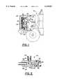
- FIG. 1is a partially cut-away view of a motor vehicle showing the interior of the engine compartment;
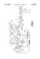
- FIG. 2is a block diagram of a system for removing gases from a motor vehicle cooling system
- FIG. 3is a cross sectional view of a venturi for creating a pressure differential the present system.
- a motor vehicle 10has a compartment 12 that houses an engine 14.
- the engine 14is connected to a conventional cooling system which comprises a radiator 16 in front of the engine and connected thereto by an upper radiator hose 18 and a lower radiator hose 20.
- a removable cap 25is attached to a neck 27 at the top of the radiator 16 for adding coolant to the cooling system.
- the cooling systemcontains a conventional liquid coolant made up of a mixture of water and an additive, such as propylene glycol.
- a pump 19forces the coolant in a closed circuit from the radiator 16 through the engine 14 and back to the radiator.
- the pump 19 and a fan 22are driven by a pulley and belt arrangement 24 on the engine. The fan draws air through the radiator 16 to remove heat from the coolant.
- FIG. 2depicts the present system 30 for removing gases that accumulate in the engine cooling system as a result of combustion gases leaking past gasket seals and air being drawn in through leaks on the suction side of the coolant pump.
- a rubber drain tube 32is attached to an overflow outlet 31 on a radiator filler neck 27 and leads to a collection container. This type of connection is commonly used to recover the coolant that is expelled from the radiator when the internal pressure rises about a predefined limit opening a pressure relief valve in the radiator cap.
- the present radiator cap 25does not have a pressure relief valve and merely seals the top opening of the filler neck 27. In other words the overflow outlet 31 always is in fluid communication with the interior of the radiator 16.
- a drain tube 32extends from the radiator overflow outlet 31 to a pressure sensing transducer 33 which produces an electrical signal indicating the radiator pressure.
- the drain tube 32also leads to a normally-open, overflow solenoid valve 34 connected in series with a check valve 35 which only allows coolant to flow from the radiator into a overflow reservoir 37.
- the overflow reservoir 36is open to the atmosphere.
- a normally-closed, inlet solenoid valve 37also is connected to the drain tube 32 to control the flow of air and coolant from the radiator 16 to an air-tight collection container 38 with seals 39 around inlet and outlet openings.
- the tube 32 from the radiator 16terminates inside container 38 near the bottom.
- a suction tube 41leads from an upper section of the collection container 38 to a normally-closed, outlet solenoid valve 43, which controls fluid flow to the suction port of a venturi 40.
- the structure of the venturi 40is illustrated in FIG. 3 and comprises a T-shaped body 42 with a center suction port 44 coupled to a tube 45 from the collection container 38.
- An inlet port 46 of the body 42has an internal sleeve 50 with a relatively small passage 52 therethrough.
- the outer end of the passage 52has a flaired opening 55 and the inner end has a very slightly flaired opening 54.
- An outlet port 56 of the venturi 40is formed by a tuning tube 58 threaded into an aperture in body 42, thereby enabling the depth to which the tuning tube extends into the body to be adjusted. Such adjustment of the tuning tube 58 depth varies the magnitude of suction developed at the suction port 44, as will be described.
- the inlet port 46 of the venturi 40is connected to an air supply solenoid valve 60 by a hose 62.
- This solenoid valve 60controls the flow of compressed air supplied through conduit 64 from a compressor 65 and storage tank 67 on the motor vehicle.
- the compressed aircan be furnished from the tank 67 that supplies the vehicle air brakes.
- the electrically operated solenoid valves 34, 37, 43 and 60are controlled by separate signals from a controller 68.
- the pressure sensing transducer 33transmits a pressure indication signal to the controller.
- the controller 68also receives an ignition signal that indicates whether or not the engine 14 is operating.
- a manual switch 72is provided so that the gas removal system 30 can be disabled by a mechanic while working on the motor vehicle 10.
- the gas removal system 30is operated occasionally to bleed gases from the engine cooling system. A significant portion of those gases accumulate at the top of the radiator 16 as that is the highest part of the cooling system.
- the gas removal system 30is activated whenever the engine 14 is turned off. Specifically, by monitoring the ignition input 70, the controller 68 is able to determine when the engine is turned off. When that event is detected the controller 68 begins monitoring the radiator pressure as indicated by the signal from the transducer 33. When that pressure has decreased to substantially the normal atmospheric pressure (e.g. 1-3 psi), as happens when the temperature of the coolant has cooled to approximately the ambient temperature, the controller 68 responds by first closing overflow solenoid valve 34 and then opening solenoid valves 37, 43 and 60.
- substantially the normal atmospheric pressuree.g. 1-3 psi
- Opening the air supply solenoid valve 60allows compressed air from supply conduit 64 to flow through the venturi 40, entering inlet port 46 and exiting the outlet port 56, as seen in FIG. 3. Because internal sleeve 50 provides a restricted passage 52, the speed of the air flow increases going through the body 42 of the venturi 40. That air flow creates a pressure in the internal venturi chamber 48 that is below atmospheric pressure, thereby creating a negative pressure at the suction port 44.
- the magnitude of the negative pressurecan be tuned to an optimum level by varying the depth to which the tuning tube 58 extends into the body 42, for example the tuning tube 58 is adjusted to provide a negative pressure of approximately seven psi.
- the pressure differentialdraws air from the collection container 38, thereby creating a partial vacuum in that container.
- other types of vacuum sourcescan be employed with the present gas removal system.
- That partial vacuumis transferred through the radiator drain tube 32 to inside the radiator filler neck 27 which draws gas, that has accumulated at the top of the radiator 16, through drain tube 32 and into the collection container 38. That gas bubbles through any coolant 76 in the bottom of the collection container 38 to suction tube 41 and through oulet soleniod valve 43 to the venturi 40 from which the gas is expelled via outlet port 56. Any coolant that is drawn from the radiator remains in the bottom of the collection container 38.
- the controller 68monitors the radiator pressure, as indicated by the signal from transducer 33. When radiator reaches a predefined negative pressure, for example 24-26 inches of vacuum, the controller 68 closes the outlet solenoid valve 43 and the air supply solenoid valve 60. This valve closure removes further suction from being applied to the collection container 38, but maintains that container at a significant negative pressure.
- the inlet solenoid valve 37remains open so that any additional air that migrates through the cooling system to the top of the radiator 16 still will be drawn into the collection container 38.
- the overflow solenoid valve 34is de-energized at this time to return to its normally-open state. However, the check valve 36 prevents air and coolant from being drawn through the overflow solenoid valve 34 into the cooling system by the negative pressure
- coolant 76 that entered the collection container 38 during the gas removal processwill be returned to the radiator 16.
- Controller 68monitors the rate at which the negative pressure decays. Too rapid a decay is an indication that the cooling system has deteriorated to a point where repair is necessary. Thus, if the radiator pressure rises by more than a given amount within a defined period of time, the controller 68 illuminates a lamp 78 on the dashboard of the motor vehicle to alert the operator that cooling system service is required.
- the controller 68opens both the inlet and outlet solenoid valves 37 and 43 to draw coolant from the collection container 38 into the radiator 16 thereby releasing any residual negative pressure.
- the coolant removed from the collection container 38is replaced by air entering through the venturi 40 and the outlet valve 43.
- These valves 37 and 43are closed by the controller 68 after a brief pressure recovery period.
Landscapes
- Engineering & Computer Science (AREA)
- Chemical & Material Sciences (AREA)
- Combustion & Propulsion (AREA)
- Mechanical Engineering (AREA)
- General Engineering & Computer Science (AREA)
- Exhaust Gas After Treatment (AREA)
Abstract
Description
Claims (18)
Priority Applications (1)
| Application Number | Priority Date | Filing Date | Title |
|---|---|---|---|
| US09/138,231US6135067A (en) | 1998-08-21 | 1998-08-21 | System removing entrapped gas from an engine cooling system |
Applications Claiming Priority (1)
| Application Number | Priority Date | Filing Date | Title |
|---|---|---|---|
| US09/138,231US6135067A (en) | 1998-08-21 | 1998-08-21 | System removing entrapped gas from an engine cooling system |
Publications (1)
| Publication Number | Publication Date |
|---|---|
| US6135067Atrue US6135067A (en) | 2000-10-24 |
Family
ID=22481068
Family Applications (1)
| Application Number | Title | Priority Date | Filing Date |
|---|---|---|---|
| US09/138,231Expired - LifetimeUS6135067A (en) | 1998-08-21 | 1998-08-21 | System removing entrapped gas from an engine cooling system |
Country Status (1)
| Country | Link |
|---|---|
| US (1) | US6135067A (en) |
Cited By (22)
| Publication number | Priority date | Publication date | Assignee | Title |
|---|---|---|---|---|
| US6532910B2 (en)* | 2001-02-20 | 2003-03-18 | Volvo Trucks North America, Inc. | Engine cooling system |
| US20030102028A1 (en)* | 2000-10-27 | 2003-06-05 | Knowles Steven M. | Method and apparatus for removing fluid from a fluid system |
| US6584994B2 (en) | 2000-10-27 | 2003-07-01 | Prime Solutions Llc | Service system and method |
| US6588445B2 (en) | 2000-10-27 | 2003-07-08 | Prime Solutions Llc | Fluid system service apparatus and method |
| US6668766B1 (en) | 2002-07-22 | 2003-12-30 | Visteon Global Technologies, Inc. | Vehicle engine cooling system with variable speed water pump |
| US6668764B1 (en) | 2002-07-29 | 2003-12-30 | Visteon Global Techologies, Inc. | Cooling system for a diesel engine |
| US6742535B1 (en) | 2000-10-27 | 2004-06-01 | Prime Solutions Llc | Method and apparatus for servicing a fluid system |
| US6745726B2 (en) | 2002-07-29 | 2004-06-08 | Visteon Global Technologies, Inc. | Engine thermal management for internal combustion engine |
| US6779350B2 (en) | 2002-03-21 | 2004-08-24 | Ritchie Enginerring Company, Inc. | Compressor head, internal discriminator, external discriminator, manifold design for refrigerant recovery apparatus and vacuum sensor |
| US6802283B2 (en) | 2002-07-22 | 2004-10-12 | Visteon Global Technologies, Inc. | Engine cooling system with variable speed fan |
| US6832491B2 (en) | 2002-03-21 | 2004-12-21 | Ritchie Engineering Company, Inc. | Compressor head, internal discriminator, external discriminator, manifold design for refrigerant recovery apparatus |
| US20050056102A1 (en)* | 2003-06-30 | 2005-03-17 | Advantest Corporation | Gas collecting device, test head and IC device testing apparatus |
| US20050061264A1 (en)* | 2001-02-20 | 2005-03-24 | Volvo Trucks North America, Inc. | Engine cooling system |
| US7591289B1 (en) | 2006-08-30 | 2009-09-22 | Hamada Jim S | Cooling system bleeder system |
| US7614283B2 (en) | 2006-04-17 | 2009-11-10 | Lincoln Industrial Corporation | Cooling system testing apparatus and methods |
| US20100037836A1 (en)* | 2008-08-17 | 2010-02-18 | Cummins Intellectual Properties, Inc. | Gas extractor for an engine coolant system |
| US20120318040A1 (en)* | 2011-06-16 | 2012-12-20 | Clifford Kratzet | System and method of detecting head gasket degradation |
| US20150345365A1 (en)* | 2012-12-10 | 2015-12-03 | Scania Cv Ab | Arrangement and procedure for pressurizing a cooling system to cool an internal combustion engine in a vehicle |
| TWI574606B (en)* | 2013-10-18 | 2017-03-11 | 技嘉科技股份有限公司 | Negative-pressure water cooling system, negative-pressure monitor and monitoring method |
| US10470337B2 (en)* | 2016-07-26 | 2019-11-05 | Fujitsu Limited | Cooling device and electronic device |
| US10480537B2 (en)* | 2014-08-27 | 2019-11-19 | Dayco Ip Holdings, Llc | Low-cost evacuator for an engine having tuned Venturi gaps |
| US10966349B1 (en)* | 2020-07-27 | 2021-03-30 | Bitfury Ip B.V. | Two-phase immersion cooling apparatus with active vapor management |
Citations (19)
| Publication number | Priority date | Publication date | Assignee | Title |
|---|---|---|---|---|
| US3576181A (en)* | 1969-06-02 | 1971-04-27 | Cummins Engine Co Inc | Apparatus for deaerating an engine cooling system |
| US3989102A (en)* | 1974-10-18 | 1976-11-02 | General Electric Company | Cooling liquid de-gassing system |
| US4052965A (en)* | 1975-10-28 | 1977-10-11 | Caterpillar Tractor Co. | Engine cooling system vent means |
| US4185751A (en)* | 1978-07-31 | 1980-01-29 | Stant Manufacturing Company, Inc. | Radiator cap |
| US4271976A (en)* | 1979-11-13 | 1981-06-09 | E. Edelmann & Co. | Combination pressure release cooling cap and recovery of coolant |
| US4549505A (en)* | 1983-10-25 | 1985-10-29 | Nissan Motor Co., Ltd. | Cooling system for automotive engine or the like |
| US4592418A (en)* | 1980-06-06 | 1986-06-03 | Valeo | Degassing device for a fluid circulating in a heat exchanger |
| US4662317A (en)* | 1985-09-06 | 1987-05-05 | Nissan Motor Co., Ltd. | Cooling system for automotive engine or the like |
| US4722305A (en)* | 1987-03-30 | 1988-02-02 | Shell Oil Company | Apparatus and method for oxidation and corrosion prevention in a vehicular coolant system |
| US4782689A (en)* | 1987-06-04 | 1988-11-08 | Derome Raymond D | Apparatus and method for testing, filling and purging closed fluid systems |
| US4888980A (en)* | 1989-04-21 | 1989-12-26 | Derome Raymond D | Apparatus and method for testing, filling and purging closed fluid systems |
| US5186242A (en)* | 1990-03-09 | 1993-02-16 | Calsonic Corporation | Condenser provided with forced cooling means |
| US5241926A (en)* | 1991-08-09 | 1993-09-07 | Mazda Motor Corporation | Engine cooling apparatus |
| US5248052A (en)* | 1992-07-31 | 1993-09-28 | Mellinger Larry L | Apparatus for automatically releasing the super-atmospheric pressure of an engine cooling system in response to turning off the engine and preventing the buildup of pressure while the engine is off |
| US5318700A (en)* | 1992-08-07 | 1994-06-07 | Wynn Oil Company | Engine and radiator coolant treatment and handling, enabling coolant reuse |
| US5353751A (en)* | 1992-09-18 | 1994-10-11 | Evans John W | Engine cooling system and radiator therefor |
| US5381762A (en)* | 1992-09-18 | 1995-01-17 | Evans; John W. | Engine cooling system and radiator therefor |
| US5390636A (en)* | 1994-02-14 | 1995-02-21 | Wynn Oil Company | Coolant transfer apparatus and method, for engine/radiator cooling system |
| US5535818A (en)* | 1992-10-12 | 1996-07-16 | Fujitsu Limited | Cooling system for electronic device |
- 1998
- 1998-08-21USUS09/138,231patent/US6135067A/ennot_activeExpired - Lifetime
Patent Citations (19)
| Publication number | Priority date | Publication date | Assignee | Title |
|---|---|---|---|---|
| US3576181A (en)* | 1969-06-02 | 1971-04-27 | Cummins Engine Co Inc | Apparatus for deaerating an engine cooling system |
| US3989102A (en)* | 1974-10-18 | 1976-11-02 | General Electric Company | Cooling liquid de-gassing system |
| US4052965A (en)* | 1975-10-28 | 1977-10-11 | Caterpillar Tractor Co. | Engine cooling system vent means |
| US4185751A (en)* | 1978-07-31 | 1980-01-29 | Stant Manufacturing Company, Inc. | Radiator cap |
| US4271976A (en)* | 1979-11-13 | 1981-06-09 | E. Edelmann & Co. | Combination pressure release cooling cap and recovery of coolant |
| US4592418A (en)* | 1980-06-06 | 1986-06-03 | Valeo | Degassing device for a fluid circulating in a heat exchanger |
| US4549505A (en)* | 1983-10-25 | 1985-10-29 | Nissan Motor Co., Ltd. | Cooling system for automotive engine or the like |
| US4662317A (en)* | 1985-09-06 | 1987-05-05 | Nissan Motor Co., Ltd. | Cooling system for automotive engine or the like |
| US4722305A (en)* | 1987-03-30 | 1988-02-02 | Shell Oil Company | Apparatus and method for oxidation and corrosion prevention in a vehicular coolant system |
| US4782689A (en)* | 1987-06-04 | 1988-11-08 | Derome Raymond D | Apparatus and method for testing, filling and purging closed fluid systems |
| US4888980A (en)* | 1989-04-21 | 1989-12-26 | Derome Raymond D | Apparatus and method for testing, filling and purging closed fluid systems |
| US5186242A (en)* | 1990-03-09 | 1993-02-16 | Calsonic Corporation | Condenser provided with forced cooling means |
| US5241926A (en)* | 1991-08-09 | 1993-09-07 | Mazda Motor Corporation | Engine cooling apparatus |
| US5248052A (en)* | 1992-07-31 | 1993-09-28 | Mellinger Larry L | Apparatus for automatically releasing the super-atmospheric pressure of an engine cooling system in response to turning off the engine and preventing the buildup of pressure while the engine is off |
| US5318700A (en)* | 1992-08-07 | 1994-06-07 | Wynn Oil Company | Engine and radiator coolant treatment and handling, enabling coolant reuse |
| US5353751A (en)* | 1992-09-18 | 1994-10-11 | Evans John W | Engine cooling system and radiator therefor |
| US5381762A (en)* | 1992-09-18 | 1995-01-17 | Evans; John W. | Engine cooling system and radiator therefor |
| US5535818A (en)* | 1992-10-12 | 1996-07-16 | Fujitsu Limited | Cooling system for electronic device |
| US5390636A (en)* | 1994-02-14 | 1995-02-21 | Wynn Oil Company | Coolant transfer apparatus and method, for engine/radiator cooling system |
Non-Patent Citations (4)
| Title |
|---|
| D. Cappert, "Let It Bleed", Super Automotive Service, pp. 22-25, Oct. 1989. |
| D. Cappert, Let It Bleed , Super Automotive Service, pp. 22 25, Oct. 1989.* |
| E. Carpenter, "Vac-U-Fill Coolant Filler", Circle Track, pp. 132-133, Feb. 1997. |
| E. Carpenter, Vac U Fill Coolant Filler , Circle Track, pp. 132 133, Feb. 1997.* |
Cited By (37)
| Publication number | Priority date | Publication date | Assignee | Title |
|---|---|---|---|---|
| US20030102028A1 (en)* | 2000-10-27 | 2003-06-05 | Knowles Steven M. | Method and apparatus for removing fluid from a fluid system |
| US6584994B2 (en) | 2000-10-27 | 2003-07-01 | Prime Solutions Llc | Service system and method |
| US6588445B2 (en) | 2000-10-27 | 2003-07-08 | Prime Solutions Llc | Fluid system service apparatus and method |
| US6612327B2 (en) | 2000-10-27 | 2003-09-02 | Prime Solutions Llc | Service system and method |
| US20040084082A1 (en)* | 2000-10-27 | 2004-05-06 | Prime Solution Llc, A Michigan Corporation | Service system and method |
| US6742535B1 (en) | 2000-10-27 | 2004-06-01 | Prime Solutions Llc | Method and apparatus for servicing a fluid system |
| US6959717B2 (en) | 2000-10-27 | 2005-11-01 | Prime Solutions Llc | Method and apparatus for removing fluid from a fluid system |
| US6883533B2 (en) | 2000-10-27 | 2005-04-26 | Prime Solutions, Inc. | Service system and method |
| US20050061264A1 (en)* | 2001-02-20 | 2005-03-24 | Volvo Trucks North America, Inc. | Engine cooling system |
| US7152555B2 (en) | 2001-02-20 | 2006-12-26 | Volvo Trucks North America, Inc. | Engine cooling system |
| US6532910B2 (en)* | 2001-02-20 | 2003-03-18 | Volvo Trucks North America, Inc. | Engine cooling system |
| US6886503B2 (en) | 2001-02-20 | 2005-05-03 | Volvo Trucks North America, Inc. | Engine cooling system |
| US6779350B2 (en) | 2002-03-21 | 2004-08-24 | Ritchie Enginerring Company, Inc. | Compressor head, internal discriminator, external discriminator, manifold design for refrigerant recovery apparatus and vacuum sensor |
| US7428822B2 (en) | 2002-03-21 | 2008-09-30 | Ritchie Engineering Company, Inc. | Vacuum sensor |
| US6832491B2 (en) | 2002-03-21 | 2004-12-21 | Ritchie Engineering Company, Inc. | Compressor head, internal discriminator, external discriminator, manifold design for refrigerant recovery apparatus |
| US7310965B2 (en) | 2002-03-21 | 2007-12-25 | Ritchie Engineering Company, Inc. | Compressor head, internal discriminator, external discriminator, manifold design for refrigeration recovery apparatus |
| US7073346B2 (en) | 2002-03-21 | 2006-07-11 | Ritchie Engineering Company, Inc. | Compressor head, internal discriminator, external discriminator, manifold design for refrigerant recovery apparatus and vacuum sensor |
| US7159412B2 (en) | 2002-03-21 | 2007-01-09 | Ritchie Engineering Company, Inc. | Compressor head, internal discriminator, external discriminator, manifold design for refrigeration recovery apparatus |
| US6802283B2 (en) | 2002-07-22 | 2004-10-12 | Visteon Global Technologies, Inc. | Engine cooling system with variable speed fan |
| US6668766B1 (en) | 2002-07-22 | 2003-12-30 | Visteon Global Technologies, Inc. | Vehicle engine cooling system with variable speed water pump |
| US6745726B2 (en) | 2002-07-29 | 2004-06-08 | Visteon Global Technologies, Inc. | Engine thermal management for internal combustion engine |
| US6668764B1 (en) | 2002-07-29 | 2003-12-30 | Visteon Global Techologies, Inc. | Cooling system for a diesel engine |
| US7072180B2 (en)* | 2003-06-30 | 2006-07-04 | Advantest Corporation | Gas collecting device, test head and IC device testing apparatus |
| US20050056102A1 (en)* | 2003-06-30 | 2005-03-17 | Advantest Corporation | Gas collecting device, test head and IC device testing apparatus |
| US7614283B2 (en) | 2006-04-17 | 2009-11-10 | Lincoln Industrial Corporation | Cooling system testing apparatus and methods |
| US7591289B1 (en) | 2006-08-30 | 2009-09-22 | Hamada Jim S | Cooling system bleeder system |
| US20100037836A1 (en)* | 2008-08-17 | 2010-02-18 | Cummins Intellectual Properties, Inc. | Gas extractor for an engine coolant system |
| US7681537B2 (en)* | 2008-08-17 | 2010-03-23 | Cummins Intellectual Properties, Inc. | Gas extractor for an engine coolant system |
| US20120318040A1 (en)* | 2011-06-16 | 2012-12-20 | Clifford Kratzet | System and method of detecting head gasket degradation |
| US20150345365A1 (en)* | 2012-12-10 | 2015-12-03 | Scania Cv Ab | Arrangement and procedure for pressurizing a cooling system to cool an internal combustion engine in a vehicle |
| TWI574606B (en)* | 2013-10-18 | 2017-03-11 | 技嘉科技股份有限公司 | Negative-pressure water cooling system, negative-pressure monitor and monitoring method |
| US10480537B2 (en)* | 2014-08-27 | 2019-11-19 | Dayco Ip Holdings, Llc | Low-cost evacuator for an engine having tuned Venturi gaps |
| EP3822135A1 (en)* | 2014-08-27 | 2021-05-19 | Dayco IP Holdings, LLC | Low-cost evacuator for an engine having tuned venturi gaps |
| US10470337B2 (en)* | 2016-07-26 | 2019-11-05 | Fujitsu Limited | Cooling device and electronic device |
| US10966349B1 (en)* | 2020-07-27 | 2021-03-30 | Bitfury Ip B.V. | Two-phase immersion cooling apparatus with active vapor management |
| US20230171923A1 (en)* | 2020-07-27 | 2023-06-01 | Liquidstack Holding B.V. | Two-phase immersion cooling apparatus with active vapor management |
| US12342502B2 (en)* | 2020-07-27 | 2025-06-24 | Liquidstack Holding B.V. | Two-phase immersion cooling apparatus with active vapor management |
Similar Documents
| Publication | Publication Date | Title |
|---|---|---|
| US6135067A (en) | System removing entrapped gas from an engine cooling system | |
| US5495749A (en) | Leak detection assembly | |
| EP1252062B1 (en) | Apparatus and method for filling a motor vehicle cooling system with coolant | |
| US6073487A (en) | Evaporative system leak detection for an evaporative emission control system | |
| US5868120A (en) | Fuel vapor management system for motor vehicles | |
| US6564780B2 (en) | Diagnostic apparatus and method for fuel vapor purge system | |
| US6260544B1 (en) | Low fuel vapor emissions fuel system | |
| US7472583B2 (en) | Evaporated fuel leakage detector for use in automotive vehicle | |
| US5437257A (en) | Evaporative emission control system with vent valve | |
| US9051905B2 (en) | Evaporative emission control system | |
| US5553577A (en) | Apparatus for checking the tightness of a tank venting system | |
| US6405718B1 (en) | Malfunction test apparatus for fuel vapor purge system | |
| KR20080069590A (en) | Fuel Steam Separator for Ship Engine with Aeration Control | |
| JP2004183663A (en) | Vacuum operated shut-off valve, and device and method for fuel vapor vent control | |
| US4100758A (en) | Vacuum assist fuel system | |
| US5044430A (en) | Method and apparatus for continuously maintaining a volume of coolant within a pressurized cooling system | |
| US4790369A (en) | Method and apparatus for continuously maintaining a volume of coolant within a pressurized cooling system | |
| JP2005504944A (en) | Combination valve for fuel system of combustion engine and the fuel system | |
| US6135136A (en) | System for draining and recovering coolant from a motor vehicle cooling system | |
| US4785874A (en) | Method and apparatus for continuously purging gaseous matter from the cooling system of an internal combustion engine | |
| US5163462A (en) | Apparatus for tapping a fluid through a wall | |
| US6202478B1 (en) | Evaporative system leak detection feature after a refueling event | |
| US5501199A (en) | Monitoring of evaporative purge system | |
| EP0707709A4 (en) | Leak detection assembly | |
| KR20120032759A (en) | Evaporative Gas Control System of Fuel |
Legal Events
| Date | Code | Title | Description |
|---|---|---|---|
| AS | Assignment | Owner name:TECH-SNAKE INC., WISCONSIN Free format text:ASSIGNMENT OF ASSIGNORS INTEREST;ASSIGNORS:KLAMM, THOMAS L.;BRAUN, ROBERT D.;REEL/FRAME:009694/0067 Effective date:19980820 | |
| AS | Assignment | Owner name:UVIEW ULTRAVIOLET SYSTEMS, INC., CANADA Free format text:ASSIGNMENT OF ASSIGNORS INTEREST;ASSIGNOR:TECH-SNAKE, INC.;REEL/FRAME:010839/0961 Effective date:20000411 | |
| STCF | Information on status: patent grant | Free format text:PATENTED CASE | |
| FPAY | Fee payment | Year of fee payment:4 | |
| FPAY | Fee payment | Year of fee payment:8 | |
| FPAY | Fee payment | Year of fee payment:12 | |
| AS | Assignment | Owner name:CPS PRODUCTS CANADA LTD., CANADA Free format text:ASSIGNMENT OF ASSIGNORS INTEREST;ASSIGNORS:UVIEW ULTRAVIOLET SYSTEMS INC.;TERRACLEAN OF ONTARIO INC.;REEL/FRAME:032891/0821 Effective date:20140506 | |
| AS | Assignment | Owner name:MADISON CAPITAL FUNDING LLC, AS AGENT, ILLINOIS Free format text:SECURITY INTEREST;ASSIGNOR:CPS PRODUCTS CANADA LTD.;REEL/FRAME:033064/0982 Effective date:20140506 | |
| AS | Assignment | Owner name:APOGEM CAPITAL LLC, SUCCESSOR AGENT, ILLINOIS Free format text:ASSIGNMENT OF INTELLECTUAL PROPERTY SECURITY AGREEMENT;ASSIGNOR:MADISON CAPITAL FUNDING LLC, AS RETIRING AGENT;REEL/FRAME:059727/0147 Effective date:20220401 |