US6134227A - Secondary channel for radio frequency communications - Google Patents
Secondary channel for radio frequency communicationsDownload PDFInfo
- Publication number
- US6134227A US6134227AUS08/841,168US84116897AUS6134227AUS 6134227 AUS6134227 AUS 6134227AUS 84116897 AUS84116897 AUS 84116897AUS 6134227 AUS6134227 AUS 6134227A
- Authority
- US
- United States
- Prior art keywords
- frequency
- radio signals
- tdd
- coupled
- oscillator
- Prior art date
- Legal status (The legal status is an assumption and is not a legal conclusion. Google has not performed a legal analysis and makes no representation as to the accuracy of the status listed.)
- Expired - Lifetime
Links
Images


Classifications
- H—ELECTRICITY
- H04—ELECTRIC COMMUNICATION TECHNIQUE
- H04B—TRANSMISSION
- H04B7/00—Radio transmission systems, i.e. using radiation field
- H04B7/24—Radio transmission systems, i.e. using radiation field for communication between two or more posts
- H04B7/26—Radio transmission systems, i.e. using radiation field for communication between two or more posts at least one of which is mobile
- H04B7/2615—Radio transmission systems, i.e. using radiation field for communication between two or more posts at least one of which is mobile using hybrid frequency-time division multiple access [FDMA-TDMA]
- H—ELECTRICITY
- H04—ELECTRIC COMMUNICATION TECHNIQUE
- H04B—TRANSMISSION
- H04B7/00—Radio transmission systems, i.e. using radiation field
- H04B7/24—Radio transmission systems, i.e. using radiation field for communication between two or more posts
- H04B7/26—Radio transmission systems, i.e. using radiation field for communication between two or more posts at least one of which is mobile
- H04B7/2621—Radio transmission systems, i.e. using radiation field for communication between two or more posts at least one of which is mobile using frequency division multiple access [FDMA]
Definitions
- This inventionrelates to radio frequency communications and, more particularly, to a frequency division duplex/time division duplex (FDD/TDD) system and method for radio frequency communication for greater quantities of information over a limited spectrum for lower cost by providing a secondary communications channel, in addition to a primary communications channel, for full duplex communication over both the primary and secondary channels.
- FDD/TDDfrequency division duplex/time division duplex
- Radio componentscan be some of the most expensive portions of radio frequency (RF) communications equipment. This is particularly the case in cordless, or wireless, telephony. In RF communications and particularly, in cordless or wireless telephony, costs and operational requirements determine the viability of communications equipment designs. The engineering designer is often presented with design constraints imposed by the costs of component, or by operational requirements. Such costs and operational requirements are particularly important considerations when communications equipment is intended for lower-end consumers, such as individuals and households.
- RFradio frequency
- Cordless phones based on analog and/or continuous variable slope delta (CVSD) digital methodsuse FDD to provide a wireless link between a base and handset. Since FDD requires two frequencies to accommodate a full-duplex link, the two carriers are used 100% of the time during a call. To adequately support two handsets an FDD base station design would require one RF transceiver for each handset. Since the cost of a cordless phone depends on not only the handset cost but the base station cost as well, the cost of the system increases.
- CVSDcontinuous variable slope delta
- Products which advertise similar capabilityeither mean a two-line (i.e. PSTN) to two handset capability, provide a second RF transceiver at the base, or are designed to allow either handset to detect an incoming call but only one to be used during a call; the second handset is then unable to share in the conversation.
- PSTNpublic switched telephone network
- CT2Cordless Telephony Second Generation
- CEPTEuropean Conference of Postal and Telecommunications Administrations
- CT1Cordless Telephony First Generation
- DECTDigital European Cordless Telecommunications
- the CT2 standardfor example, employs a time division duplex (TDD) system and methodology.
- TDDtime division duplex
- transmit and receive communicationsoccur among two stations, such as, for example, a handset and base set unit of a cordless telephone, in a burst manner at distinct intervals of time.
- stationssuch as, for example, a handset and base set unit of a cordless telephone
- devices conforming to CT2have transmitted and received over an identical carrier frequency within the bandwidth dictated by the standard. Communications have been possible in TDD units because different time intervals are employed for transmissions and receptions by each station. During an interval that one station is transmitting, the other is receiving, and vice versa, over the same bandwidth.
- Devices built according to the CT2 standardhave been considered more spectrally efficient than FDD based devices.
- FDDfrequency division duplex
- transmit and receive communicationsoccur over two distinct, separate carrier channels.
- two FDD communications stationssuch as, for example, a handset unit and a base set unit of a cordless telephone, each transmit and receive over different carrier channels. While a first unit is transmitting over a particular channel at a first frequency, the second unit is receiving on that same channel over the same frequency. When the second unit transmits, it does so on a separate channel at a second frequency and the first unit receives or that different channel at that second frequency.
- FDD systemstend to be less expensive than TDD systems because of their analog nature of conveying voice signals over a communications channel when compared to the digital nature of TDD based systems.
- Spread spectrum communications technologyIn spread spectrum communications technology, a sequential noise-like signal structure is employed to spread normally narrow band information signals over a relatively wide band of frequencies. The receiver in such systems correlates the special spectrum transmission signals to retrieve the original information being transmitted.
- Spread spectrum technologyprovides certain benefits, such as greater information over one channel.
- a disadvantage of spread spectrum technologyis increased expense because significant processing capacity is necessary to transmit and receive over the broad spectrum of frequencies employed.
- TDD methodscan be advantageous because of the minimal spectrum necessary for such communications.
- FDD methodsprovide advantages of continuous and simultaneous transmission and reception and lower system cost. The limitations of both such methods, though, are apparent, as previously discussed.
- the newer communications methodsalso provide certain advantages, but they do so only at greater expense or by use of more frequency spectrum. It would, therefore, be a significant improvement in the art and technology to provide an improved system and method for radio frequency communication which is low cost, and yet allows for communications of larger amounts of continuous and simultaneous information, such as voice and data information.
- the present inventionemploys a unique system and method for a hybrid digital FDD/TDD radio frequency communications format in which a secondary channel is provided to allow radio frequency communications between two mobile units and a base unit over the channels to occur concurrently.
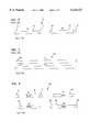
- FIGS. 1a and 1billustrate the FDD and TDD schemes of the prior art.
- An embodiment of the inventionis a method of digital radio frequency communications over a first channel and a second channel, each channel employing a different carrier frequency.
- the methodcomprises the steps of transmitting first information during a first time interval, over the first channel, at a first frequency, transmitting second information during a second time interval, over the first channel, at the first frequency, receiving first information during the second time interval, over the second channel, at a second frequency, and receiving second information during the first time interval, over the second channel at the second frequency.
- FIG. 1cAnother embodiment of the invention is a method of radio frequency communications between two mobile handset units and a base unit. This is illustrated in FIG. 1c.
- the methodcomprises the steps of transmitting information during a first time interval over a first frequency by a first mobile unit, transmitting information during a second time interval over the first frequency by a second mobile unit, transmitting information by the base unit to the second mobile unit during the first time interval over a second frequency, and transmitting information by the base unit to the first mobile unit during the second time interval over the second frequency.
- an embodiment of the present invention for a cordless phoneincludes a single base station having one RF module and two handsets. This embodiment allows connection to existing PSTN communication channels with no special requirements. During normal operation, the base station is connected to the PSTN with the two handset units able to roam freely within a defined perimeter, such as a business or residential setting.
- An advantage of this two handset embodiment for cordless phonesis that it provides flexibility by using the FDD/TDD scheme of the present invention, described herein, which is preferably implemented on a 900 MHz digital narrow-band design.
- Yet another embodiment of the inventionis a system for radio frequency communications over a first frequency and a second frequency.
- the systemtransmits and receives communications, including first information and second information, in bursts during time intervals, including a first time interval and a second time interval.
- the systemcomprises circuitry for transmitting the first information during the first time interval, over the first frequency, circuitry for transmitting the second information during the second time interval, over the second frequency, circuitry for receiving the first information during the first time interval, over the first frequency, and circuitry for receiving the second information during the second time interval, over the second frequency.
- Another embodiment of the inventionis a system for radio frequency communications between a first unit and a second unit.
- the communicationsare conducted over a first frequency and a second frequency.
- the first unit and the second unittransmit and receive communications, including first, second, third and fourth information, in bursts over select time intervals, including a first time interval and a second time interval.
- the systemcomprises circuitry for transmitting the first information during the first time interval over the first frequency by the first unit, circuitry for receiving the first information during the first time interval over the first frequency by the second unit, circuitry for transmitting the second information during the second time interval over the second frequency by first unit, circuitry for receiving the second information during the second time interval over the second frequency by the second unit, circuitry for transmitting the third information during the first time interval over the second frequency by the second unit, circuitry for receiving the third information during the first time interval over the second frequency by the first unit, circuitry for transmitting the fourth information during the second time interval over the first frequency by the second unit, and circuitry for receiving the fourth information during the second time interval over the first frequency by the first unit.
- Yet another embodiment of the inventionis a method of radio frequency communications.
- the methodcomprises the steps of first transmitting by a first unit, first receiving by the first unit simultaneously with the step of first transmitting, second transmitting by a second unit non-simultaneously with the step of first transmitting, and second receiving by the second unit simultaneously with the step of second transmitting.
- FIGS. 1a and 1bare illustrative of the FDD and TDD communications schemes of the prior art
- FIG. 1cdepicts an embodiment of a hybrid FDD/TDD scheme of the present invention
- FIG. 2is an illustration of transmit and receive signals of a RF communications unit employing a TDD approach, wherein both transmission and reception occur over the same frequency channel;
- FIG. 3is an illustration of transmit and receive signals by a RF communications unit employing a FDD methodology, wherein transmit and receive signals pass over different frequency channels;
- FIG. 4is an illustration of transmissions and receptions by a unit employing in embodiment of the hybrid FDD/TDD RF communications approach of the present invention, wherein two carrier channels are employed for frequency division duplexed transmissions; receptions, and such transmissions and receptions are burst in a time division manner;
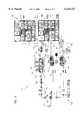
- FIG. 5is an architectural embodiment of a device for performing the FDD/TDD dual channel RF communications according to the present invention, which device allows for simultaneous transmission and reception of voice and data information;
- FIG. 6schematically illustrates one embodiment of the FDD/TDD RF communication system and a frame structure of the present invention.
- FIG. 7schematically illustrates an embodiment of the frame structure of the communication system of the present invention.
- the following detailed descriptionaddresses certain embodiments of a novel system and method for providing radio frequency communications over a secondary channel concurrently during radio frequency communications over a primary channel, employing FDD/TDD RF communications.
- the FDD/TDD schemeis illustrated in FIG. 6 showing an embodiment of the invention where two mobile handset units 100, 102 are in communication with A single base unit 104.
- a first channel 106 and a second channel 108are used to facilitate digital communications between each handset unit 100, 102 and base unit 104. See FIG. 1c.
- Channels 106 and 108operate at different frequencies. The invention is explained by reference to prior TDD and FDD technology.
- transmit (T x )12 and receive (R x )14 communications of a device operating according to FDD principlesare illustrated.
- FDD signal transmissions 12are accomplished over a first carrier frequency and signal receptions 14 are accomplished over a second carrier frequency.
- the transmission 12 over timeis depicted by the top box and the reception 14 over time is depicted by the bottom box.
- the vertical displacement of the two boxesis employed to indicate that two separate carrier frequencies serve for transmission 12 and reception 14, respectively.
- the same displacement representationis used in FIG. 4 for the same reason.
- timeprogresses in passing from left to right across the page.
- this FDD methodologyis like that employed in cordless telephones operating according to the CT1 standard.
- analog signalsare passed between communication devices as transmissions 12 and receptions 14.
- Operation over separate frequencies for transmit 12 and receive 14 communicationshas previously required more devices or components, such as, for example, radio components, in order to perform such communications, and so FDD methodology devices can be relatively expensive when supporting more than one channel.
- FDD operationsoccur over the separate frequencies for transmission 12 and receptions 14, more spectrum may be used up in FDD communications, at least in comparison to typical TDD communications.
- transmit 4, 6, 7 and receive 5, 8, 9 signal sequences of a TDD communications deviceare depicted.
- the communicationsare digitized by converting he communications, for example, voice or data, into a binary pattern.
- the digital binary patternis then buffered and transmitted at a high rate in bursts at distinct intervals of time. Only a single carrier frequency may be necessary for TDD communications. Time division of transmissions 4, 6, 7 and receptions 5, 8, 9 into distinct time intervals allows both receive 5, 8, 9 and transmit 4, 6, 7 signals to be accomplished over the single frequency.
- both the left and right boxesrepresent digitized communications being transmitted and received throughout periods of time.
- the box on the leftrepresents a transmission (T x ) 4, 6, 7.
- the transmission 4, 6, 7may include certain beginning transmit control bits 4 and certain transmitted information bits 6.
- the information bits 6may, for example, be digitized voice or data signals.
- the transmission 4, 6, 7may also include end control bits 7.
- the transmission 4, 6, 7occurs on a particular carrier frequency and is burst over distinct intervals of time.
- reception (R x ) 5, 8, 9 of communicated informationoccurs over the same carrier frequency as the transmission 4, 6, 7, but at different intervals of time. This interval of time for reception 5, 8, 9 is different from the interval of the transmission 4, 6, 7.
- the reception 5, 8, 9may include beginning control bits 5, received information bits 8 and ending control bits 9. Because distinct intervals of time are set for transmissions 4, 6, 7 and receptions 5, 8, 9, the same carrier frequency can support both transmissions 4, 6, 7 and receptions 5, 8, 9, albeit at those different intervals of time.
- the TDD communication sequence illustrated hereis the type performed by the prior communications units which conform to the CT2 standard for cordless telephones.
- both transmissions 4, 6, 7 and receptions 5, 8, 9occur over the same carrier in the typical TDD manner.
- the interval during which both transmission 4, 6, 7 and reception 5, 8, 9 occursis two milliseconds long.
- the standardprovides that 66/68 bits can be transmitted (4, 6, 7) or received (5, 8, 9) by a CT2 device.
- a disadvantage of prior communications devices conforming to the CT2 standardhas been cost of the devices.
- FIG. 4it may be understood how the present invention employs a new FDD/TDD approach to enable simultaneous communications over two separate channels, a primary communications channel and a secondary communications channel.
- Transmission of voice 4, 6, 7 and data 24 and reception of data 22 and voice 28, 26, 30 according to the FDD/TDD approach of the present inventionare illustrated.
- an RF communications unit 120(FIG. 5), that is the "radio front end" of a base unit 118 (FIG. 5) is designed and configured to employ FDD in a TDD manner.
- Such an RF Communications unit 120 (FIG. 5)may be employed with a cordless telephone digital base unit 52 (FIG. 5) that operates according to TDD methodology.
- the FDD/TDD approachemploys a dual duplex design, i.e., a first carrier channel for transmission of digital signals by two handset units, and a different, second carrier channel for reception of digital communications by the two handset units to a base unit. Over each carrier channel, communications are passed in bursts of distinct time intervals in a time division manner. Such an arrangement allows greater amounts of information, for example, both voice and data, to be simultaneously communicated.
- transmission of voice (T x ) 4, 6, 7 and transmission of data (T x ) 24 by a first unitoccur over a first carrier channel in separate, distinct time intervals.
- reception of data (R x ) 22 and voice (R x ) 28, 26, 30cicurs over a second carrier channel in separate, distinct time intervals coinciding with the transmission time intervals.
- transmission of voice 4, 6, 7 and reception of data 22can occur simultaneously and transmission of data 24 and reception of voice 28, 26, 30 can occur simultaneously, each in distinct and different time intervals, over dual carrier frequencies.
- a communications unitsuch as a cordless handset unit transmits and receives by the scheme shown in FIG. 4, significantly more information can be passed between units, even though it is being passed over only two channels.
- a communications unitsuch as a cordless handset unit transmits and receives by the scheme shown in FIG. 4
- significantly more informationcan be passed between units, even though it is being passed over only two channels.
- the prior technologysuch as in single channel TDD methods the same channel has previously been used in a time division manner only to allow both transmission 4, 6, 7 and reception 5, 8, 9 (See FIG. 2).
- frequency divisionhas previously been used only by employing different channels for transmission 12 and reception 14 (See FIG. 3).
- the present inventiontakes advantage of both the particular advantages realized from TDD and FDD by incorporating the two concepts in the mariner previously described, at low cost.
- the TDD frame structure of FIG. 4defines a burst structure for transmission of signaling channel bits 4, 7 which are meant for system control and 64 bits of voice data 6, and also the same burst structure for bit reception, i.e., control bits 28, 30 and voice data 26.
- an FDD/TDD dual channel RF communications portion 120 of base unit 118the FDD/TDD base unit 118 may have the following, characteristics in a communications system comprised of a pair of cordless handset units and a base unit, as shown in FIG. 6.
- the handsetsmay, for example, cover the range of about 902 MHz to about 904 MHz
- the base station receivermay, for example, cover the range of about 925.5 MHz to about 927.5 MHz, both in 100 KHz increments.
- the portion 120includes an antenna 122 for communicating with the handset units.
- the antenna 122is connected with an antenna duplexer 124, for example, two bandpass filters, 126 and 127.
- the duplexer 124which includes filters 126 and 127, operates to distinguish receptions and transmissions of the portion 120 and to allow them to be received and transmitted over the appropriate frequency by the base unit 118.
- Received signalsare thereafter amplified, filtered, detected and converted to received information (R x ) 145 for use by master and slave (35, 37) controllers of base unit 118.
- the received signalsafter leaving duplexer 124, pass to a first bandpass filter 126, for example, a 2-pole dielectric resonator bandpass device, then to a low noise RF amplifier 128, for example, having a common emitter design. If desired, the amplifier 128 may be powered only during periods in which receptions are being received, to conserve power.
- the output of the amplifier 128connects with a second bandpass filter 130.
- the filter 130serves to improve the overall image rejection and to filter the image noise caused by the amplifier 128.
- the output of the second bandpass filter 130connects to the input of a mixer 132. Also connected as an input to the mixer 132 is the output of a first synthesizer 183 through a buffer amplifier 133.
- the mixer 132converts the amplified and filtered received signal to an intermediate frequency.
- the output from the mixer 132is filtered by a first intermediate frequency filter 134, for example, a ceramic device which may save a bandwidth of approximately 10.7 MHz.
- the intermediate frequency signalis then input to an intermediate frequency (IF) demodulator subsystem 136.
- the subsystem 136receives the intermediate frequency signal and amplifies, filters and limits it, and generates receive baseband (R x ) signal 144 and receive signal strength indicator (RSSI) output signal 146.
- the first stage of the subsystem 136may be a mixer which can be used to convert the input intermediate frequency signal to a second intermediate frequency signal if the application so requires it. However, in some applications, the second intermediate frequency signal may be amplified.
- the mixermay be converted to provide the amplification by generating a DC imbalance in a Gilbert Cell 139, such as by altering the biasing of a crystal oscillator provided through a resistor connected to ground.
- the amplified signalmay then be input to a second intermediate frequency filter 137.
- the output of that filterconnects to an intermediate frequency amplifier that drives a final intermediate frequency filter 138 that connects to a limiter.
- the limiteradds gain and reduces FM noise and rejects AM.
- the output of the limitermay be coupled to an input of a multiplier.
- a phase-shifted version of that output from the limiteris connected to another input of the multiplier.
- the phase-shiftmay be provided, for example, by a parallel tuned circuit which may be adjusted so that such output and such phase-shifted version of the output are in quadrature.
- the output of the multiplieris the recovered receive baseband signal prior to being amplified and restored.
- the receive signal strength indicator (RSSI) signal 146 from the subsystem 136may be passed to the baseband processor slave controller 37 of the base unit digital unit 52.
- the RSSI signal 146may be produced by the subsystem 136 by monitoring the current drawn in the limiter stages.
- the subsystem 136may pass the receive baseband signal 144 to post detection processing circuitry. Thereafter, the filtered and perhaps amplified receive baseband signal 144 may be passed to a squaring circuit to reconstitute the digital data.
- the squaring circuitmay include, for example, a filter 140 and a slicer 142.
- the slicer 142converts the baseband signal 144 to a digital signal, preferably using a 1 bit quantizer.
- the digital signalis passed on to the base unit digital unit 52 as the received (R x Data) signal 145.
- a signal from a local oscillator 152is input to a first synthesizer 183 as a reference.
- the first synthesizer 183tales the signal from oscillator 152 and drives a divide-by-P prescaler and divide-by-N counter.
- the output of the divide-by-N countermay be connected to an input of a phase/frequency detector.
- the output of the divide-by-R countermay connect to a reference input of the phase/frequency detector.
- the detectorgenerates an error signal that is used to drive the first synthesizer 183 onto a first programmed frequency which is the primary communications channel.
- the first synthesizer 183connects with a voltage regulator 100 to minimize noise.
- the reception side circuitryserves to receive the received signals, whether voice 28, 26, 30 or data 22 (FIG. 4), depending on the particular time interval at a select first RF frequency of the primary carrier channel and render the received signals useable by the base unit digital unit 52 as a digital received signal 145.
- the transmit side circuitryalso includes a synthesizer 154.
- the synthesizer 154may, for example, be a phase-locked loop utilizing the oscillator crystal 152 for reference generation.
- a digital baseband transmit signal 160is generated in a TDD manner by the slave portion 37 of base unit digital unit 52 by, for example, a TDD burst mode controller.
- Signal 160may be buttered by buffer amplifier 161.
- An output of the divide-by-N counter of synthesizer 154may be connected to an input of a phase/frequency detector.
- transmit side circuitrymay accept the signal 175 output from synthesizer 154.
- the signal 175may then be buffered by buffer amplifier 172.
- a power amplifier 174may then amplify the signal 175 after it passes through a bandpass filter 162.
- the transmit stagemay be powered only during transmit intervals.
- the stagemay, for example, deliver about zero dBm to the antenna duplexer 124. In that example, the transmit output level at the antenna 122 may be about -1 dBm.
- the components and connections indicated on FIG. 5are examples of a possible configuration of the FDD/TDD RF dual communications portion 120.
- the frequency shift between transmissions of voice 4, 6, 7 and data 24, on the one hand, and receptions of data 22 and voice 28, 26, 30, on the other handis preferably about 23.5 MHz and the receive signal frequency is at about 903 MHz for the transmit signal and is at 926.5 for the receive channel.
- the particular frequency shift and receive and transmit signal frequenciesare only an example of possible configurations employing the FDD/TDD approach of the present invention.
- the present inventionallows a single base unit, having one RF module, to communicate with two handset units.
- the base unituses specific frame structures in conjunction with a signaling channel to indicate, preferably, call incoming information, call releasing information, or as a means of addressing a handset unit. Similar frame structures are used by the handset units to indicate, preferably, call originating information, call answering information, call clear-down information, or an identifying address signal.
- the combination of different frame structures in combination with individual l.D.s uniquely assigned to the base unit and each handset unitprevents communication between the base unit and handset units not paired to that unit. That is, a radio link can only be set up when a unique combination of signaling messages and I.D.s are exchanged between a base unit and a paired handset unit.
- both frame structurescontain a synchronization channel comprised of a 24-bit pattern referred to as a channel marker and a one-zero preamble pattern.
- the channel markeris referenced as a first signal if originated from a base unit, or as a second signal if originated from a handset unit. The identification of each may be different.
- the channel marker sent by the base unit to the handset unitmay be the inverse of the channel marker sent by the handset to the base and, therefore, unless the detection and/or synchronization hardware is flexible with regard to the handling of these channel markers, it would be unlikely that a handset unit would link up with another handset unit unless the necessary code and/or hardware reconfiguration of one handset to act as a base unit was included.
- a handset unitdetects a channel marker pattern, it obtains frame synchronization from the channel marker pattern and then examines the message in the signaling channel to ascertain if a call is to be received. If a call is received, the handset unit responds with a certain command frame in conjunction with an appropriate response in the signaling channel.
- FIG. 7illustrates the frame structure of the transmission and reception of signals between the two handset units and the base unit.
- the architectural embodimentsserve to set the frequenzy of the transmitted signal at a select frequency at a select shift from the received signal but, nonetheless, within the limits of the desired frequency range for the device.
- transmissions and receptionsoccur in a FDD manner in the embodiment, transmissions and receptions may occur simultaneously because of the TDD operation. This is so because the frequency duplexed communications over separate channels are also time duplexed on each of the separate channels. This enables simultaneous communication between two handset units and a single base.
Landscapes
- Engineering & Computer Science (AREA)
- Computer Networks & Wireless Communication (AREA)
- Signal Processing (AREA)
- Mobile Radio Communication Systems (AREA)
- Time-Division Multiplex Systems (AREA)
Abstract
Description
Claims (11)
Priority Applications (4)
| Application Number | Priority Date | Filing Date | Title |
|---|---|---|---|
| US08/841,168US6134227A (en) | 1995-12-04 | 1997-04-29 | Secondary channel for radio frequency communications |
| JP54698798AJP2001522562A (en) | 1997-04-29 | 1998-03-27 | Secondary channel for radio frequency communication |
| EP98914335AEP0979563A1 (en) | 1997-04-29 | 1998-03-27 | Secondary channel for radio frequency communications |
| PCT/US1998/006110WO1998049791A1 (en) | 1997-04-29 | 1998-03-27 | Secondary channel for radio frequency communications |
Applications Claiming Priority (2)
| Application Number | Priority Date | Filing Date | Title |
|---|---|---|---|
| US56713395A | 1995-12-04 | 1995-12-04 | |
| US08/841,168US6134227A (en) | 1995-12-04 | 1997-04-29 | Secondary channel for radio frequency communications |
Related Parent Applications (1)
| Application Number | Title | Priority Date | Filing Date |
|---|---|---|---|
| US56713395AContinuation-In-Part | 1995-12-04 | 1995-12-04 |
Publications (1)
| Publication Number | Publication Date |
|---|---|
| US6134227Atrue US6134227A (en) | 2000-10-17 |
Family
ID=25284204
Family Applications (1)
| Application Number | Title | Priority Date | Filing Date |
|---|---|---|---|
| US08/841,168Expired - LifetimeUS6134227A (en) | 1995-12-04 | 1997-04-29 | Secondary channel for radio frequency communications |
Country Status (4)
| Country | Link |
|---|---|
| US (1) | US6134227A (en) |
| EP (1) | EP0979563A1 (en) |
| JP (1) | JP2001522562A (en) |
| WO (1) | WO1998049791A1 (en) |
Cited By (50)
| Publication number | Priority date | Publication date | Assignee | Title |
|---|---|---|---|---|
| US6321095B1 (en)* | 1999-03-26 | 2001-11-20 | Sherman Gavette | Wireless communications approach |
| US6356765B1 (en)* | 1999-07-27 | 2002-03-12 | Legerity, Inc. | Method and apparatus for tracking signals |
| US6556830B1 (en)* | 1998-02-02 | 2003-04-29 | Ericsson Inc. | Coverage area sectorization in time division multiple access/frequency-time division duplex communications systems |
| US20030119490A1 (en)* | 2001-02-26 | 2003-06-26 | Jahangir Mohammed | Wireless communications handset for facilitating licensed and unlicensed wireless communications, and method of operation |
| US6587444B1 (en)* | 1997-11-14 | 2003-07-01 | Ericsson Inc. | Fixed frequency-time division duplex in radio communications systems |
| US20040037241A1 (en)* | 2002-08-22 | 2004-02-26 | Kwangju Institue Of Science And Technology | Interlaced frequency division duplexing method for duplex communication system |
| US20050227715A1 (en)* | 2002-08-22 | 2005-10-13 | Riedl Wilhelm E | Low-cost high-power digital cordless telephone architecture |
| US6956836B2 (en)* | 2001-05-17 | 2005-10-18 | Ericsson, Inc. | Asymmetric frequency allocation for packet channels in a wireless network |
| US6975603B1 (en)* | 1999-08-20 | 2005-12-13 | Siemens Communications Inc. | System and method for minimizing the loss of information in cordless communications |
| EP1626608A1 (en)* | 2004-08-10 | 2006-02-15 | NTT DoCoMo, Inc. | Slot allocation apparatus and slot allocation method |
| US7107055B2 (en) | 2002-10-18 | 2006-09-12 | Kineto, Wireless, Inc. | Mobile station GPRS implementation for switching between licensed and unlicensed wireless systems |
| US7272397B2 (en) | 2003-10-17 | 2007-09-18 | Kineto Wireless, Inc. | Service access control interface for an unlicensed wireless communication system |
| US7283822B2 (en) | 2003-10-17 | 2007-10-16 | Kineto Wireless, Inc. | Service access control interface for an unlicensed wireless communication system |
| US7308263B2 (en) | 2001-02-26 | 2007-12-11 | Kineto Wireless, Inc. | Apparatus for supporting the handover of a telecommunication session between a licensed wireless system and an unlicensed wireless system |
| US20080062914A1 (en)* | 2006-09-08 | 2008-03-13 | Nextel Communications, Inc. | System and method for radio frequency resource allocation |
| US7349698B2 (en) | 2002-10-18 | 2008-03-25 | Kineto Wireless, Inc. | Registration messaging in an unlicensed mobile access telecommunications system |
| US7369859B2 (en) | 2003-10-17 | 2008-05-06 | Kineto Wireless, Inc. | Method and system for determining the location of an unlicensed mobile access subscriber |
| US7430188B1 (en)* | 1999-03-05 | 2008-09-30 | Nokia Corporation | Data transmission method and radio link system |
| US7466978B1 (en)* | 2000-09-18 | 2008-12-16 | International Business Machines Corporation | Telephone network node device |
| US7471655B2 (en) | 2003-10-17 | 2008-12-30 | Kineto Wireless, Inc. | Channel activation messaging in an unlicensed mobile access telecommunications system |
| US20090059260A1 (en)* | 2007-08-31 | 2009-03-05 | Brother Kogyo Kabushiki Kaisha | Multifunction peripheral |
| US7515575B1 (en) | 2005-08-26 | 2009-04-07 | Kineto Wireless, Inc. | Intelligent access point scanning with self-learning capability |
| US7565145B2 (en) | 2002-10-18 | 2009-07-21 | Kineto Wireless, Inc. | Handover messaging in an unlicensed mobile access telecommunications system |
| US7606190B2 (en) | 2002-10-18 | 2009-10-20 | Kineto Wireless, Inc. | Apparatus and messages for interworking between unlicensed access network and GPRS network for data services |
| US7634269B2 (en) | 2002-10-18 | 2009-12-15 | Kineto Wireless, Inc. | Apparatus and method for extending the coverage area of a licensed wireless communication system using an unlicensed wireless communication system |
| US7640008B2 (en) | 2002-10-18 | 2009-12-29 | Kineto Wireless, Inc. | Apparatus and method for extending the coverage area of a licensed wireless communication system using an unlicensed wireless communication system |
| US20100067411A1 (en)* | 2007-08-31 | 2010-03-18 | Fujitsu Limited | Wireless Access Method And Apparatus |
| US7756546B1 (en) | 2005-03-30 | 2010-07-13 | Kineto Wireless, Inc. | Methods and apparatuses to indicate fixed terminal capabilities |
| US7843900B2 (en) | 2005-08-10 | 2010-11-30 | Kineto Wireless, Inc. | Mechanisms to extend UMA or GAN to inter-work with UMTS core network |
| US7852817B2 (en) | 2006-07-14 | 2010-12-14 | Kineto Wireless, Inc. | Generic access to the Iu interface |
| US7873015B2 (en) | 2002-10-18 | 2011-01-18 | Kineto Wireless, Inc. | Method and system for registering an unlicensed mobile access subscriber with a network controller |
| US7885644B2 (en) | 2002-10-18 | 2011-02-08 | Kineto Wireless, Inc. | Method and system of providing landline equivalent location information over an integrated communication system |
| US7912004B2 (en) | 2006-07-14 | 2011-03-22 | Kineto Wireless, Inc. | Generic access to the Iu interface |
| US7933598B1 (en) | 2005-03-14 | 2011-04-26 | Kineto Wireless, Inc. | Methods and apparatuses for effecting handover in integrated wireless systems |
| US7953423B2 (en) | 2002-10-18 | 2011-05-31 | Kineto Wireless, Inc. | Messaging in an unlicensed mobile access telecommunications system |
| US7957348B1 (en) | 2004-04-21 | 2011-06-07 | Kineto Wireless, Inc. | Method and system for signaling traffic and media types within a communications network switching system |
| US20110182335A1 (en)* | 2007-01-22 | 2011-07-28 | Freescale Semiconductor, Inc. | Calibration signal generator |
| US7995994B2 (en) | 2006-09-22 | 2011-08-09 | Kineto Wireless, Inc. | Method and apparatus for preventing theft of service in a communication system |
| US8005076B2 (en) | 2006-07-14 | 2011-08-23 | Kineto Wireless, Inc. | Method and apparatus for activating transport channels in a packet switched communication system |
| US8019331B2 (en) | 2007-02-26 | 2011-09-13 | Kineto Wireless, Inc. | Femtocell integration into the macro network |
| US8036664B2 (en) | 2006-09-22 | 2011-10-11 | Kineto Wireless, Inc. | Method and apparatus for determining rove-out |
| US8041385B2 (en) | 2004-05-14 | 2011-10-18 | Kineto Wireless, Inc. | Power management mechanism for unlicensed wireless communication systems |
| US8041335B2 (en) | 2008-04-18 | 2011-10-18 | Kineto Wireless, Inc. | Method and apparatus for routing of emergency services for unauthorized user equipment in a home Node B system |
| US8073428B2 (en) | 2006-09-22 | 2011-12-06 | Kineto Wireless, Inc. | Method and apparatus for securing communication between an access point and a network controller |
| US8150397B2 (en) | 2006-09-22 | 2012-04-03 | Kineto Wireless, Inc. | Method and apparatus for establishing transport channels for a femtocell |
| US8165086B2 (en) | 2006-04-18 | 2012-04-24 | Kineto Wireless, Inc. | Method of providing improved integrated communication system data service |
| US8204502B2 (en) | 2006-09-22 | 2012-06-19 | Kineto Wireless, Inc. | Method and apparatus for user equipment registration |
| US20140010125A1 (en)* | 2012-07-05 | 2014-01-09 | Fredrik Tillman | Method and Apparatus for Carrier Aggregation |
| US9490857B2 (en) | 2002-09-20 | 2016-11-08 | Iii Holdings 1, Llc | Systems and methods for parallel signal cancellation |
| US9648644B2 (en) | 2004-08-24 | 2017-05-09 | Comcast Cable Communications, Llc | Determining a location of a device for calling via an access point |
Families Citing this family (2)
| Publication number | Priority date | Publication date | Assignee | Title |
|---|---|---|---|---|
| WO1999026362A1 (en)* | 1997-11-14 | 1999-05-27 | Ericsson Inc. | Frequency-time division duplex in radio communications systems |
| FI107306B (en)* | 1999-04-13 | 2001-06-29 | Nokia Mobile Phones Ltd | Procedure in a wireless data transfer system as well as a wireless data transfer system |
Citations (13)
| Publication number | Priority date | Publication date | Assignee | Title |
|---|---|---|---|---|
| US4129749A (en)* | 1976-06-24 | 1978-12-12 | Goldman Stephen R | Radio telephone communications system |
| US5134710A (en)* | 1988-10-17 | 1992-07-28 | Telefonaktiebolaget L M Ericsson | Method of transmitting call information in a short range mobile telephone system and a radio unit for carrying out the method |
| WO1993017507A1 (en)* | 1992-02-28 | 1993-09-02 | Telefonaktiebolaget Lm Ericsson | A method for communication in a tdma cellular mobile radio system using frequency hopping |
| US5428601A (en)* | 1990-07-23 | 1995-06-27 | U.S. Philips Corporation | Method of operating a communications system, a communications system and a secondary station for use in the system |
| WO1995025406A1 (en)* | 1994-03-15 | 1995-09-21 | Telstra Corporation Limited | A method and apparatus for frequency allocation in a cellular telecommunications network |
| EP0677930A1 (en)* | 1994-04-15 | 1995-10-18 | Alcatel Mobile Communication France | TDMA method with frame multiframe structure signal therefor |
| US5475677A (en)* | 1994-12-29 | 1995-12-12 | Bell Communications Research Inc. | Compatible licensed and unlicensed band portable handset unit for TDMA wireless communications system |
| US5515366A (en)* | 1994-11-17 | 1996-05-07 | International Business Machines Corporation | Method and apparatus for direct communication in a TDMA radio communication system |
| US5533027A (en)* | 1993-02-16 | 1996-07-02 | Telefonaktiebolaget Lm Ericsson | Digital fixed radio access system providing local mobility |
| US5566168A (en)* | 1994-01-11 | 1996-10-15 | Ericsson Ge Mobile Communications Inc. | TDMA/FDMA/CDMA hybrid radio access methods |
| GB2306083A (en)* | 1995-10-06 | 1997-04-23 | Nippon Telegraph & Telephone | TDMA communication system |
| WO1997021287A1 (en)* | 1995-12-04 | 1997-06-12 | Advanced Micro Devices, Inc. | System and method for frequency division duplex/time division duplex radio frequency communications |
| US5812522A (en)* | 1995-03-31 | 1998-09-22 | Airtouch Communications, Inc. | Location-ruled radio-integrated network |
- 1997
- 1997-04-29USUS08/841,168patent/US6134227A/ennot_activeExpired - Lifetime
- 1998
- 1998-03-27EPEP98914335Apatent/EP0979563A1/ennot_activeWithdrawn
- 1998-03-27JPJP54698798Apatent/JP2001522562A/enactivePending
- 1998-03-27WOPCT/US1998/006110patent/WO1998049791A1/ennot_activeApplication Discontinuation
Patent Citations (13)
| Publication number | Priority date | Publication date | Assignee | Title |
|---|---|---|---|---|
| US4129749A (en)* | 1976-06-24 | 1978-12-12 | Goldman Stephen R | Radio telephone communications system |
| US5134710A (en)* | 1988-10-17 | 1992-07-28 | Telefonaktiebolaget L M Ericsson | Method of transmitting call information in a short range mobile telephone system and a radio unit for carrying out the method |
| US5428601A (en)* | 1990-07-23 | 1995-06-27 | U.S. Philips Corporation | Method of operating a communications system, a communications system and a secondary station for use in the system |
| WO1993017507A1 (en)* | 1992-02-28 | 1993-09-02 | Telefonaktiebolaget Lm Ericsson | A method for communication in a tdma cellular mobile radio system using frequency hopping |
| US5533027A (en)* | 1993-02-16 | 1996-07-02 | Telefonaktiebolaget Lm Ericsson | Digital fixed radio access system providing local mobility |
| US5566168A (en)* | 1994-01-11 | 1996-10-15 | Ericsson Ge Mobile Communications Inc. | TDMA/FDMA/CDMA hybrid radio access methods |
| WO1995025406A1 (en)* | 1994-03-15 | 1995-09-21 | Telstra Corporation Limited | A method and apparatus for frequency allocation in a cellular telecommunications network |
| EP0677930A1 (en)* | 1994-04-15 | 1995-10-18 | Alcatel Mobile Communication France | TDMA method with frame multiframe structure signal therefor |
| US5515366A (en)* | 1994-11-17 | 1996-05-07 | International Business Machines Corporation | Method and apparatus for direct communication in a TDMA radio communication system |
| US5475677A (en)* | 1994-12-29 | 1995-12-12 | Bell Communications Research Inc. | Compatible licensed and unlicensed band portable handset unit for TDMA wireless communications system |
| US5812522A (en)* | 1995-03-31 | 1998-09-22 | Airtouch Communications, Inc. | Location-ruled radio-integrated network |
| GB2306083A (en)* | 1995-10-06 | 1997-04-23 | Nippon Telegraph & Telephone | TDMA communication system |
| WO1997021287A1 (en)* | 1995-12-04 | 1997-06-12 | Advanced Micro Devices, Inc. | System and method for frequency division duplex/time division duplex radio frequency communications |
Cited By (95)
| Publication number | Priority date | Publication date | Assignee | Title |
|---|---|---|---|---|
| US6587444B1 (en)* | 1997-11-14 | 2003-07-01 | Ericsson Inc. | Fixed frequency-time division duplex in radio communications systems |
| US6556830B1 (en)* | 1998-02-02 | 2003-04-29 | Ericsson Inc. | Coverage area sectorization in time division multiple access/frequency-time division duplex communications systems |
| US7430188B1 (en)* | 1999-03-05 | 2008-09-30 | Nokia Corporation | Data transmission method and radio link system |
| US6321095B1 (en)* | 1999-03-26 | 2001-11-20 | Sherman Gavette | Wireless communications approach |
| US6356765B1 (en)* | 1999-07-27 | 2002-03-12 | Legerity, Inc. | Method and apparatus for tracking signals |
| US6975603B1 (en)* | 1999-08-20 | 2005-12-13 | Siemens Communications Inc. | System and method for minimizing the loss of information in cordless communications |
| US7466978B1 (en)* | 2000-09-18 | 2008-12-16 | International Business Machines Corporation | Telephone network node device |
| US7308263B2 (en) | 2001-02-26 | 2007-12-11 | Kineto Wireless, Inc. | Apparatus for supporting the handover of a telecommunication session between a licensed wireless system and an unlicensed wireless system |
| US7720481B2 (en) | 2001-02-26 | 2010-05-18 | Kineto Wireless, Inc. | Apparatus for supporting the handover of a telecommunication session between a licensed wireless system and an unlicensed wireless system |
| US7574213B2 (en) | 2001-02-26 | 2009-08-11 | Kineto Wireless, Inc. | Apparatus for supporting the handover of a telecommunication session between a licensed wireless system and an unlicensed wireless system |
| US20030119490A1 (en)* | 2001-02-26 | 2003-06-26 | Jahangir Mohammed | Wireless communications handset for facilitating licensed and unlicensed wireless communications, and method of operation |
| US8160588B2 (en) | 2001-02-26 | 2012-04-17 | Kineto Wireless, Inc. | Method and apparatus for supporting the handover of a telecommunication session between a licensed wireless system and an unlicensed wireless system |
| US7996009B2 (en) | 2001-02-26 | 2011-08-09 | Kineto Wireless, Inc. | Method for authenticating access to an unlicensed wireless communications system using a licensed wireless communications system authentication process |
| US7890099B2 (en) | 2001-02-26 | 2011-02-15 | Kineto Wireless, Inc. | Method for automatic and seamless call transfers between a licensed wireless system and an unlicensed wireless system |
| US6956836B2 (en)* | 2001-05-17 | 2005-10-18 | Ericsson, Inc. | Asymmetric frequency allocation for packet channels in a wireless network |
| US20040037241A1 (en)* | 2002-08-22 | 2004-02-26 | Kwangju Institue Of Science And Technology | Interlaced frequency division duplexing method for duplex communication system |
| US20050227715A1 (en)* | 2002-08-22 | 2005-10-13 | Riedl Wilhelm E | Low-cost high-power digital cordless telephone architecture |
| US9490857B2 (en) | 2002-09-20 | 2016-11-08 | Iii Holdings 1, Llc | Systems and methods for parallel signal cancellation |
| US9544044B2 (en) | 2002-09-20 | 2017-01-10 | Iii Holdings 1, Llc | Systems and methods for parallel signal cancellation |
| US9647708B2 (en) | 2002-09-20 | 2017-05-09 | Iii Holdings 1, Llc | Advanced signal processors for interference cancellation in baseband receivers |
| US7684803B2 (en) | 2002-10-18 | 2010-03-23 | Kineto Wireless, Inc. | Network controller messaging for ciphering in an unlicensed wireless communication system |
| US7197309B2 (en) | 2002-10-18 | 2007-03-27 | Kineto Wireless, Inc. | Mobile station ciphering configuration procedure in an unlicensed wireless communication system |
| US7283821B2 (en) | 2002-10-18 | 2007-10-16 | Kineto Wireless, Inc. | Radio resources messaging for a mobile station in an unlicensed wireless communication system |
| US7107055B2 (en) | 2002-10-18 | 2006-09-12 | Kineto, Wireless, Inc. | Mobile station GPRS implementation for switching between licensed and unlicensed wireless systems |
| US7324818B2 (en) | 2002-10-18 | 2008-01-29 | Kineto Wireless, Inc | Mobile station implementation for switching between licensed and unlicensed wireless systems |
| US8165585B2 (en) | 2002-10-18 | 2012-04-24 | Kineto Wireless, Inc. | Handover messaging in an unlicensed mobile access telecommunications system |
| US7349698B2 (en) | 2002-10-18 | 2008-03-25 | Kineto Wireless, Inc. | Registration messaging in an unlicensed mobile access telecommunications system |
| US7127250B2 (en) | 2002-10-18 | 2006-10-24 | Kineto Wireless, Inc. | Apparatus and method for extending the coverage area of a licensed wireless communication system using an unlicensed wireless communication system |
| US7369854B2 (en) | 2002-10-18 | 2008-05-06 | Kineto Wireless, Inc. | Release of radio resources in an unlicensed wireless communication system |
| US7245916B2 (en) | 2002-10-18 | 2007-07-17 | Kineto Wireless, Inc. | Radio resources messaging in an unlicensed wireless communication system |
| US8130703B2 (en) | 2002-10-18 | 2012-03-06 | Kineto Wireless, Inc. | Apparatus and messages for interworking between unlicensed access network and GPRS network for data services |
| US7215961B2 (en) | 2002-10-18 | 2007-05-08 | Kineto Wireless, Inc. | Registration messaging for a mobile station in an unlicensed wireless communication system |
| US8090371B2 (en) | 2002-10-18 | 2012-01-03 | Kineto Wireless, Inc. | Network controller messaging for release in an unlicensed wireless communication system |
| US7171205B2 (en) | 2002-10-18 | 2007-01-30 | Kineto Wireless, Inc. | Architecture of an unlicensed wireless communication system with a generic access point |
| US20090082022A1 (en)* | 2002-10-18 | 2009-03-26 | Gallagher Michael D | Mobile station messaging for ciphering in an unlicensed wireless communication system |
| US7974624B2 (en) | 2002-10-18 | 2011-07-05 | Kineto Wireless, Inc. | Registration messaging in an unlicensed mobile access telecommunications system |
| US7953423B2 (en) | 2002-10-18 | 2011-05-31 | Kineto Wireless, Inc. | Messaging in an unlicensed mobile access telecommunications system |
| US7565145B2 (en) | 2002-10-18 | 2009-07-21 | Kineto Wireless, Inc. | Handover messaging in an unlicensed mobile access telecommunications system |
| US7212819B2 (en) | 2002-10-18 | 2007-05-01 | Kineto Wireless, Inc. | GPRS signaling protocol architecture for an unlicensed wireless communication system |
| US7606568B2 (en) | 2002-10-18 | 2009-10-20 | Kineto Wireless, Inc. | Messaging for registration in an unlicensed wireless communication system |
| US7606190B2 (en) | 2002-10-18 | 2009-10-20 | Kineto Wireless, Inc. | Apparatus and messages for interworking between unlicensed access network and GPRS network for data services |
| US7634270B2 (en) | 2002-10-18 | 2009-12-15 | Kineto Wireless, Inc. | GPRS data protocol architecture for an unlicensed wireless communication system |
| US7634269B2 (en) | 2002-10-18 | 2009-12-15 | Kineto Wireless, Inc. | Apparatus and method for extending the coverage area of a licensed wireless communication system using an unlicensed wireless communication system |
| US7634271B2 (en) | 2002-10-18 | 2009-12-15 | Kineto Wireless, Inc. | GSM signaling protocol architecture for an unlicensed wireless communication system |
| US7640008B2 (en) | 2002-10-18 | 2009-12-29 | Kineto Wireless, Inc. | Apparatus and method for extending the coverage area of a licensed wireless communication system using an unlicensed wireless communication system |
| US7668558B2 (en) | 2002-10-18 | 2010-02-23 | Kineto Wireless, Inc. | Network controller messaging for paging in an unlicensed wireless communication system |
| US7949326B2 (en) | 2002-10-18 | 2011-05-24 | Kineto Wireless, Inc. | Apparatus and method for extending the coverage area of a licensed wireless communication system using an unlicensed wireless communication system |
| US7209744B2 (en) | 2002-10-18 | 2007-04-24 | Kineto Wireless, Inc. | Registration messaging for an unlicensed wireless communication system |
| US7200399B2 (en) | 2002-10-18 | 2007-04-03 | Kineto Wireless, Inc. | Ciphering configuration procedure in an unlicensed wireless communication system |
| US7885644B2 (en) | 2002-10-18 | 2011-02-08 | Kineto Wireless, Inc. | Method and system of providing landline equivalent location information over an integrated communication system |
| US7769385B2 (en) | 2002-10-18 | 2010-08-03 | Kineto Wireless, Inc. | Mobile station messaging for registration in an unlicensed wireless communication system |
| US7773993B2 (en) | 2002-10-18 | 2010-08-10 | Kineto Wireless, Inc. | Network controller messaging for channel activation in an unlicensed wireless communication system |
| US7818007B2 (en) | 2002-10-18 | 2010-10-19 | Kineto Wireless, Inc. | Mobile station messaging for ciphering in an unlicensed wireless communication system |
| US7873015B2 (en) | 2002-10-18 | 2011-01-18 | Kineto Wireless, Inc. | Method and system for registering an unlicensed mobile access subscriber with a network controller |
| US7471655B2 (en) | 2003-10-17 | 2008-12-30 | Kineto Wireless, Inc. | Channel activation messaging in an unlicensed mobile access telecommunications system |
| US7454207B2 (en) | 2003-10-17 | 2008-11-18 | Kineto Wireless, Inc. | Service access control interface for an unlicensed wireless communication system |
| US7283822B2 (en) | 2003-10-17 | 2007-10-16 | Kineto Wireless, Inc. | Service access control interface for an unlicensed wireless communication system |
| US7369859B2 (en) | 2003-10-17 | 2008-05-06 | Kineto Wireless, Inc. | Method and system for determining the location of an unlicensed mobile access subscriber |
| US7272397B2 (en) | 2003-10-17 | 2007-09-18 | Kineto Wireless, Inc. | Service access control interface for an unlicensed wireless communication system |
| US7929977B2 (en) | 2003-10-17 | 2011-04-19 | Kineto Wireless, Inc. | Method and system for determining the location of an unlicensed mobile access subscriber |
| US7957348B1 (en) | 2004-04-21 | 2011-06-07 | Kineto Wireless, Inc. | Method and system for signaling traffic and media types within a communications network switching system |
| US8041385B2 (en) | 2004-05-14 | 2011-10-18 | Kineto Wireless, Inc. | Power management mechanism for unlicensed wireless communication systems |
| EP1626608A1 (en)* | 2004-08-10 | 2006-02-15 | NTT DoCoMo, Inc. | Slot allocation apparatus and slot allocation method |
| US20060034239A1 (en)* | 2004-08-10 | 2006-02-16 | Ntt Docomo, Inc. | Slot allocation apparatus and slot allocation method |
| US7522924B2 (en) | 2004-08-10 | 2009-04-21 | Ntt Docomo, Inc. | Slot allocation apparatus and slot allocation method |
| US10070466B2 (en) | 2004-08-24 | 2018-09-04 | Comcast Cable Communications, Llc | Determining a location of a device for calling via an access point |
| US9648644B2 (en) | 2004-08-24 | 2017-05-09 | Comcast Cable Communications, Llc | Determining a location of a device for calling via an access point |
| US10517140B2 (en) | 2004-08-24 | 2019-12-24 | Comcast Cable Communications, Llc | Determining a location of a device for calling via an access point |
| US11252779B2 (en) | 2004-08-24 | 2022-02-15 | Comcast Cable Communications, Llc | Physical location management for voice over packet communication |
| US11956852B2 (en) | 2004-08-24 | 2024-04-09 | Comcast Cable Communications, Llc | Physical location management for voice over packet communication |
| US7933598B1 (en) | 2005-03-14 | 2011-04-26 | Kineto Wireless, Inc. | Methods and apparatuses for effecting handover in integrated wireless systems |
| US7756546B1 (en) | 2005-03-30 | 2010-07-13 | Kineto Wireless, Inc. | Methods and apparatuses to indicate fixed terminal capabilities |
| US8045493B2 (en) | 2005-08-10 | 2011-10-25 | Kineto Wireless, Inc. | Mechanisms to extend UMA or GAN to inter-work with UMTS core network |
| US7843900B2 (en) | 2005-08-10 | 2010-11-30 | Kineto Wireless, Inc. | Mechanisms to extend UMA or GAN to inter-work with UMTS core network |
| US7904084B2 (en) | 2005-08-26 | 2011-03-08 | Kineto Wireless, Inc. | Intelligent access point scanning with self-learning capability |
| US7515575B1 (en) | 2005-08-26 | 2009-04-07 | Kineto Wireless, Inc. | Intelligent access point scanning with self-learning capability |
| US8165086B2 (en) | 2006-04-18 | 2012-04-24 | Kineto Wireless, Inc. | Method of providing improved integrated communication system data service |
| US7852817B2 (en) | 2006-07-14 | 2010-12-14 | Kineto Wireless, Inc. | Generic access to the Iu interface |
| US7912004B2 (en) | 2006-07-14 | 2011-03-22 | Kineto Wireless, Inc. | Generic access to the Iu interface |
| US8005076B2 (en) | 2006-07-14 | 2011-08-23 | Kineto Wireless, Inc. | Method and apparatus for activating transport channels in a packet switched communication system |
| US20080062914A1 (en)* | 2006-09-08 | 2008-03-13 | Nextel Communications, Inc. | System and method for radio frequency resource allocation |
| US8204502B2 (en) | 2006-09-22 | 2012-06-19 | Kineto Wireless, Inc. | Method and apparatus for user equipment registration |
| US8073428B2 (en) | 2006-09-22 | 2011-12-06 | Kineto Wireless, Inc. | Method and apparatus for securing communication between an access point and a network controller |
| US8036664B2 (en) | 2006-09-22 | 2011-10-11 | Kineto Wireless, Inc. | Method and apparatus for determining rove-out |
| US7995994B2 (en) | 2006-09-22 | 2011-08-09 | Kineto Wireless, Inc. | Method and apparatus for preventing theft of service in a communication system |
| US8150397B2 (en) | 2006-09-22 | 2012-04-03 | Kineto Wireless, Inc. | Method and apparatus for establishing transport channels for a femtocell |
| US20110182335A1 (en)* | 2007-01-22 | 2011-07-28 | Freescale Semiconductor, Inc. | Calibration signal generator |
| US8976849B2 (en)* | 2007-01-22 | 2015-03-10 | Freescale Semiconductor, Inc. | Calibration signal generator |
| US8019331B2 (en) | 2007-02-26 | 2011-09-13 | Kineto Wireless, Inc. | Femtocell integration into the macro network |
| US20090059260A1 (en)* | 2007-08-31 | 2009-03-05 | Brother Kogyo Kabushiki Kaisha | Multifunction peripheral |
| US8194574B2 (en)* | 2007-08-31 | 2012-06-05 | Fujitsu Limited | Wireless access method and apparatus determining communication carriers to be used in uplink and downlink based on type of service |
| US20100067411A1 (en)* | 2007-08-31 | 2010-03-18 | Fujitsu Limited | Wireless Access Method And Apparatus |
| US8041335B2 (en) | 2008-04-18 | 2011-10-18 | Kineto Wireless, Inc. | Method and apparatus for routing of emergency services for unauthorized user equipment in a home Node B system |
| US9300395B2 (en)* | 2012-07-05 | 2016-03-29 | Telefonaktiebolaget L M Ericsson (Publ) | Method and apparatus for carrier aggregation |
| US20140010125A1 (en)* | 2012-07-05 | 2014-01-09 | Fredrik Tillman | Method and Apparatus for Carrier Aggregation |
Also Published As
| Publication number | Publication date |
|---|---|
| EP0979563A1 (en) | 2000-02-16 |
| WO1998049791A1 (en) | 1998-11-05 |
| JP2001522562A (en) | 2001-11-13 |
Similar Documents
| Publication | Publication Date | Title |
|---|---|---|
| US6134227A (en) | Secondary channel for radio frequency communications | |
| EP1026908B1 (en) | Dual mode mobile phone operating as a two-way radio and corresponding method | |
| JP3095414B2 (en) | Mobile communication and data terminal with multiple operation modes | |
| JP3070656B2 (en) | Method and apparatus for improving spectrum efficiency | |
| EP0818936B1 (en) | Channel usage monitoring arrangement for base station | |
| WO1995023485A1 (en) | Multi-mode communications system | |
| JPH0775151A (en) | Interface device for connecting base station to private branch switchboard | |
| EP0996241B1 (en) | Mobile communication system | |
| US5956326A (en) | System and method for frequency division duplex/time division duplex radio frequency communication | |
| US6085109A (en) | Wireless telephone equipment operating as a cordless and cellular telephone | |
| JPH04170825A (en) | Radio communication system | |
| CA2078406C (en) | Quadrature modulator for tdma/tdd radio communication apparatus. | |
| CN1132579A (en) | Base Station Equipment Using Diversity Reception | |
| Fisher | Advanced mobile phone service: A subscriber set for the equipment test | |
| KR960012983B1 (en) | Offset Down Switch for Two Handset Cordless Phone Systems | |
| EP0439583B1 (en) | Method of, and primary station for, operating a telephone system | |
| KR19980069086A (en) | Calling device between mobile devices of wireless telephone and method | |
| JP3646146B2 (en) | Wireless phone base unit | |
| CN1077579A (en) | The frequency offset method and the equipment that are used for transceiver | |
| KR100595591B1 (en) | Walkie-talkie mobile communication terminal | |
| JP2890941B2 (en) | Wireless telephone device and wireless telephone system | |
| JPH08508377A (en) | Wireless repeater | |
| KR100189638B1 (en) | Data communication method using dtmf of cordless phone | |
| JP3192870B2 (en) | Cordless telephone | |
| KR100724223B1 (en) | Transmitting / receiving method of mobile terminal and mobile terminal that can be used as a cordless phone |
Legal Events
| Date | Code | Title | Description |
|---|---|---|---|
| AS | Assignment | Owner name:ADVANCED MICRO DEVICES, INC., CALIFORNIA Free format text:ASSIGNMENT OF ASSIGNORS INTEREST;ASSIGNOR:MAGANA, JAVIER V.;REEL/FRAME:008799/0818 Effective date:19970428 | |
| STCF | Information on status: patent grant | Free format text:PATENTED CASE | |
| AS | Assignment | Owner name:MORGAN STANLEY & CO. INCORPORATED, NEW YORK Free format text:SECURITY INTEREST;ASSIGNOR:LEGERITY, INC.;REEL/FRAME:011601/0539 Effective date:20000804 | |
| AS | Assignment | Owner name:LEGERITY, INC., TEXAS Free format text:ASSIGNMENT OF ASSIGNORS INTEREST;ASSIGNOR:ADVANCED MICRO DEVICES, INC.;REEL/FRAME:011700/0686 Effective date:20000731 | |
| CC | Certificate of correction | ||
| AS | Assignment | Owner name:MORGAN STANLEY & CO. INCORPORATED, AS FACILITY COL Free format text:SECURITY AGREEMENT;ASSIGNORS:LEGERITY, INC.;LEGERITY HOLDINGS, INC.;LEGERITY INTERNATIONAL, INC.;REEL/FRAME:013372/0063 Effective date:20020930 | |
| FPAY | Fee payment | Year of fee payment:4 | |
| AS | Assignment | Owner name:SAXON IP ASSETS LLC, TEXAS Free format text:ASSIGNMENT OF ASSIGNORS INTEREST;ASSIGNOR:LEGERITY, INC.;REEL/FRAME:019246/0747 Effective date:20070504 | |
| AS | Assignment | Owner name:LEGERITY, INC., TEXAS Free format text:RELEASE OF SECURITY INTEREST;ASSIGNOR:MORGAN STANLEY SENIOR FUNDING INC., AS ADMINISTRATIVE AGENT, SUCCESSOR TO MORGAN STANLEY & CO. INCORPORATED, AS FACILITY COLLATERAL AGENT;REEL/FRAME:019699/0854 Effective date:20070727 Owner name:LEGERITY, INC., TEXAS Free format text:RELEASE OF SECURITY INTEREST;ASSIGNOR:MORGAN STANLEY SENIOR FUNDING INC., AS ADMINISTRATIVE AGENT, SUCCESSOR TO MORGAN STANLEY & CO. INCORPORATED;REEL/FRAME:019690/0647 Effective date:20070727 Owner name:LEGERITY HOLDINGS, INC., TEXAS Free format text:RELEASE OF SECURITY INTEREST;ASSIGNOR:MORGAN STANLEY SENIOR FUNDING INC., AS ADMINISTRATIVE AGENT, SUCCESSOR TO MORGAN STANLEY & CO. INCORPORATED, AS FACILITY COLLATERAL AGENT;REEL/FRAME:019699/0854 Effective date:20070727 Owner name:LEGERITY INTERNATIONAL, INC., TEXAS Free format text:RELEASE OF SECURITY INTEREST;ASSIGNOR:MORGAN STANLEY SENIOR FUNDING INC., AS ADMINISTRATIVE AGENT, SUCCESSOR TO MORGAN STANLEY & CO. INCORPORATED, AS FACILITY COLLATERAL AGENT;REEL/FRAME:019699/0854 Effective date:20070727 | |
| AS | Assignment | Owner name:SAXON INNOVATIONS, LLC, TEXAS Free format text:ASSIGNMENT OF ASSIGNORS INTEREST;ASSIGNOR:SAXON IP ASSETS, LLC;REEL/FRAME:020072/0622 Effective date:20071016 | |
| FPAY | Fee payment | Year of fee payment:8 | |
| FEPP | Fee payment procedure | Free format text:PAYOR NUMBER ASSIGNED (ORIGINAL EVENT CODE: ASPN); ENTITY STATUS OF PATENT OWNER: LARGE ENTITY | |
| AS | Assignment | Owner name:RPX CORPORATION,CALIFORNIA Free format text:ASSIGNMENT OF ASSIGNORS INTEREST;ASSIGNOR:SAXON INNOVATIONS, LLC;REEL/FRAME:024202/0302 Effective date:20100324 | |
| AS | Assignment | Owner name:SAMSUNG ELECTRONICS CO., LTD.,KOREA, DEMOCRATIC PE Free format text:ASSIGNMENT OF ASSIGNORS INTEREST;ASSIGNOR:RPX CORPORATION;REEL/FRAME:024263/0633 Effective date:20100420 | |
| FEPP | Fee payment procedure | Free format text:PAYER NUMBER DE-ASSIGNED (ORIGINAL EVENT CODE: RMPN); ENTITY STATUS OF PATENT OWNER: LARGE ENTITY Free format text:PAYOR NUMBER ASSIGNED (ORIGINAL EVENT CODE: ASPN); ENTITY STATUS OF PATENT OWNER: LARGE ENTITY | |
| FPAY | Fee payment | Year of fee payment:12 |