US6134010A - Imaging system using polarization effects to enhance image quality - Google Patents
Imaging system using polarization effects to enhance image qualityDownload PDFInfo
- Publication number
- US6134010A US6134010AUS09/235,253US23525399AUS6134010AUS 6134010 AUS6134010 AUS 6134010AUS 23525399 AUS23525399 AUS 23525399AUS 6134010 AUS6134010 AUS 6134010A
- Authority
- US
- United States
- Prior art keywords
- polarization
- light
- spots
- section
- beams
- Prior art date
- Legal status (The legal status is an assumption and is not a legal conclusion. Google has not performed a legal analysis and makes no representation as to the accuracy of the status listed.)
- Expired - Lifetime
Links
Images


Classifications
- G—PHYSICS
- G01—MEASURING; TESTING
- G01J—MEASUREMENT OF INTENSITY, VELOCITY, SPECTRAL CONTENT, POLARISATION, PHASE OR PULSE CHARACTERISTICS OF INFRARED, VISIBLE OR ULTRAVIOLET LIGHT; COLORIMETRY; RADIATION PYROMETRY
- G01J4/00—Measuring polarisation of light
- G—PHYSICS
- G02—OPTICS
- G02B—OPTICAL ELEMENTS, SYSTEMS OR APPARATUS
- G02B21/00—Microscopes
- G02B21/0004—Microscopes specially adapted for specific applications
- G02B21/002—Scanning microscopes
- G02B21/0024—Confocal scanning microscopes (CSOMs) or confocal "macroscopes"; Accessories which are not restricted to use with CSOMs, e.g. sample holders
- G02B21/0032—Optical details of illumination, e.g. light-sources, pinholes, beam splitters, slits, fibers
- G—PHYSICS
- G02—OPTICS
- G02B—OPTICAL ELEMENTS, SYSTEMS OR APPARATUS
- G02B21/00—Microscopes
- G02B21/0004—Microscopes specially adapted for specific applications
- G02B21/002—Scanning microscopes
- G02B21/0024—Confocal scanning microscopes (CSOMs) or confocal "macroscopes"; Accessories which are not restricted to use with CSOMs, e.g. sample holders
- G02B21/0052—Optical details of the image generation
- G02B21/0056—Optical details of the image generation based on optical coherence, e.g. phase-contrast arrangements, interference arrangements
- G—PHYSICS
- G02—OPTICS
- G02B—OPTICAL ELEMENTS, SYSTEMS OR APPARATUS
- G02B21/00—Microscopes
- G02B21/0004—Microscopes specially adapted for specific applications
- G02B21/002—Scanning microscopes
- G02B21/0024—Confocal scanning microscopes (CSOMs) or confocal "macroscopes"; Accessories which are not restricted to use with CSOMs, e.g. sample holders
- G02B21/0052—Optical details of the image generation
- G02B21/0068—Optical details of the image generation arrangements using polarisation
Definitions
- the present inventionrelates to imaging systems which enhance image quality by reducing noise which reduces contrast in images especially images obtained from turbid media, such as encountered in biological specimens, and especially dermatological tissue wherein keratin is present.
- Mediawhich are turbid, may be characterized by having a high rms refractive index variation and high scattering cross sections.
- the inventionis especially suitable for use in confocal microscopy and especially in laser scanning confocal microscopes such as the Vivascope confocal scanning laser microscope sold by Lucid Technologies, Inc. of Henrietta, New York, U.S.A. and described in an article by M. Rajadhyaksha, et al. entitled "In Vivo Confocal Scanning Laser Microscopy of Human Skin, Melanin Provides Strong Contrast" that appeared in the Journal of Investigative Dermatology, Volume 104, No. 6 pg. 1 (June 1995) and also the subject matter of an article by M. Rajadhyaksha and James M. Zavislan which appeared in Laser Focus World, pg.
- the focal region(image plane or section) may be at the surface of the specimen or embedded in the specimen. Noise due to scattering sites away from the focal region may occur, whether the region is at the surface or embedded in the specimen.
- the section being imaged, especially in imaging of biological tissue,is of the thickness of a cell, for example about five microns.
- Regions adjacent to the section of interestmay have an abundance of scatterers both behind and ahead of the section in the direction of propagation of the illuminating beam which is incident on the section. These potential scattering sources are illuminated by the same optical field that illuminate the region of interest. There is a finite probability that return light from these scatterers will pass through a confocal aperture and reach the detector as optical signals from which the image of the section of interest is constructed. The spurious return light may manifest itself as speckle in the image.
- the use of sheared circularly polarized beams, in accordance with the inventionhas been found to reduce such distortion, and especially speckle distortion, thereby providing additional contrast and enhancing the image quality.
- Laser scanning confocal microscopyprovides image enhancement in that laser light beams are used, especially beams of a wavelength, such as in the infra-red range, which are maximally transmitted.
- the confocal aperturerestricts the section which is imaged to the focal region. The probability, nevertheless exists that scattered light from regions away from the focal region will pass through the confocal aperture and produce noise, especially speckle, which distort and reduce contrast in the image which is detected. It has been proposed to use light restricted to one polarization state, but only for surface reflection reduction by eliminating the other polarization state. It has also been proposed to use sheared beams and differential interference contrast to enhance microscope images.
- Nomarski microscopySuch beams have been obtained using Nomarski or Wollaston prisms and the technique of using such sheared beams has been referred to as Nomarski microscopy. See D. L. Lessor et al. "Quantitative Surface Topography Determination by Nomarski Reflection Microscopy", Journal of the Optical Society of America, Volume 69 No. 2, pg. 357 (February 1979). Nomarski microscopy techniques have also been proposed for use in confocal microscopy. See C. J. Cogswell, “Confocal Differential Interference Contrast (DIC) Microscopy", Journal of Microcopy, Vol. 165, Part I, pp. 81-101 (January 1992). Even with Nomarski techniques applied to confocal microscopy, noise distortion, which appears to emanate from scattering sites adjacent to the focal plane or image plane of interest, has not been minimized.
- the spotsmay be laterally offset or vertically offset and provide different modalities for imaging whereby different images are formed which can be combined, additively or subtractively or by otherwise relating corresponding pixels (multiplicatively or divisibly).
- the noise reduction system described hereinhas application to optical coherence imaging often referred to as optical coherence-domain reflectivity, optical coherence tomography or optical coherence microscopy.
- optical coherence imagingoften referred to as optical coherence-domain reflectivity, optical coherence tomography or optical coherence microscopy.
- a low-coherence sourceis used to illuminate a interferometer with a phase-modulated reference arm and a sample arm.
- a focusing objectivedirects light into a sample, often a turbid biological specimen.
- a system embodying the inventionenables viewing of section of a medium.
- Lightis received by and returned from the section and from sites adjacent to the section.
- the systemutilizes a polarization separator, such as Nomarski or Wollaston prism, or a Dyson type lens, and a polarization retarder, such as a quarter wavelength plate, both operative on laser light which is incident on the medium and which are disposed successively in the direction of the incident light.
- the separator and retarderprocess the incident light into light which is polarized generally circularly and in opposite senses.
- This oppositely handed polarized lightis incident on the medium in the section being imaged at spots which are spaced laterally or vertically, respectively, depending upon whether the prism or the lens polarization separator is used, and nominally in the plane of the section of interest providing interference of light returned from the sites (scatterers) adjacent to the section being imaged.
- the imagemay be constructed in response to a polarization parameter, for example the degree of circular dichroism, of the return light.
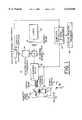
- FIG. 1is a schematic diagram of a laser scanning confocal microscope which embodies the invention
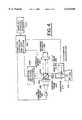
- FIG. 2is a schematic diagram illustrating the polarization processing, in the microscope of FIG. 1, of the incident light and the collection of the return light from an image section which is shown as a focal plane;
- FIG. 3is a schematic diagram showing the collection optics in the return arm of a confocal microscope system of the type illustrated in FIG. 1 which detects the ellipticity of polarization (providing an ellipsometer) and enables the construction of the image in response thereto;
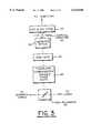
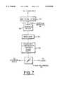
- FIG. 4is a schematic diagram of an optical coherence imaging system embodying the invention.
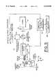
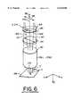
- FIGS. 5, 6, 7 and 8are diagrams similar to FIGS. 1, 2, 3 and 4 respectively, but where a Dyson type lens is used as the polarization separator.
- FIG. 1there is shown a confocal laser scanning microscope wherein the beam, which is made incident on and illuminates a turbid sample 12, is obtained from a single mode laser 14, which in the case where the microscope is used to image a section of dermatological tissue (forming the turbid sample 12), is preferably in the infra-red range.
- the incident beam from the laseris linearly polarized as indicated by the arrow 16.
- a polarizing beam spitter 18passes the incident beam to scanning optics 20.
- These scanning opticsprovide scanning in an X, Y direction, where X and Y are coordinates orthogonal to each other in the image plane.
- the scanning opticsmay be an undulating or pivoting mirror and a rotating polygon mirror as in the Vivascope laser scanning confocal microscope referenced above.
- Orthogonal mirrorsmay provide the scanning optics, as in the confocal scanning microscope described in the above-referenced publications.
- the scanning opticsis controlled by a computer controller 22 which also collects image data from a photo detector 24 and constructs the image either on a display, printer or a recorder 26.
- the incident and return beamsare deflected by a mirror 28 toward the sample 12 and pass through an objective lens system 30 to the focal or image plane in the specimen.
- Optical polarization processing elements 32are disposed in the beam path ahead of the objective 30.
- the return light from the image planeis again deflected by the scanning optics 20 and deflected by the beamsplitter 18 through detector optics (a condenser lens system) 34 to the detector.
- the detector opticsfocuses the light at the center of a confocal aperture 36.
- the objective 30 together with the polarization processing optics 32(which may be an assembly) is movable under control of the computer controller 22 in the Z direction which is a direction perpendicular to the X and Y direction as shown at 40. So far described, except for the processing elements, the confocal laser scanning microscope 10 is similar to that described in the referenced article and patent application.
- the polarization processing optics 32is provided by a Wollaston, but preferably a Nomarski, prism 42 and a quarter wave phase retarder or plate 44 which interposes a quarter wave or 90 degrees phase delay at the laser wavelength.
- This retarder 44may be a plate of transparent, bi-refringent material such a quartz, calcite, etc.
- the state of polarization of the incident beamcontains polarization components parallel and perpendicular to the optical axis 48 of the upper section 50 of prism 42. For example, linear polarization at 45° as shown in FIG. 2.
- the optical axis of the lower section 52 of the prismis orthogonal to the optical axis 48 of the upper section 50.
- optical axesare determined by the crystal structure of the prism structure. Light polarized perpendicular to the optical axis is passed through the prism section without extraordinary refraction.
- optical axis of crystalssee Yariv et al., "Optical Waves in Crystals", published by John Wiley and Sons (1984), especially section 4.2.
- the prism 42splits or shears the incident beam 56 into two linearly polarized beams, A and B.
- the axes of polarization for the two beamsare parallel to each of the optical axes of the two prisms in the Nomarski's prism.
- the shearis in a direction transverse to the direction of propagation of the incident bean 56.
- Both beamspass through a 90° phase retarder 44 with its fast axis 45° to each polarization axis of beams A and B.
- the beams A and Bare focused at spots C and D, respectively in the focal or image plane 58.
- spotsare scanned in X, Y, and Z over the image plane in order to provide optical signals from which the image can be constructed, after detection by the detector 24, in the computer 22.
- the spotsPreferably the spots substantially overlap. They are suitable separated by a distance, D/4, where D is the Airy diameter of focal spots formed by the objective 30.
- the lightis returned and collected by the objective 30 and combined inside of the prism 42, and returned as general elliptically polarized beam.
- the polarization state of the light returned from the spots C and Ddepends upon the optical activity and optical retardance, particularly the difference in the average refractive index across the spots C and D. Accordingly, the amount of light from the image plane, which is focused by the condenser 34 and passes through the confocal aperture as the optical signal which is detected by the detector, 24 depends upon the amount of polarization rotation, or the differential interference which produces a phase rotation of the polarization vector.
- the intensity of illumination at the detectordepends upon the rotation and polarization (in effect the degree of elliptical polarization) which is produced by the material in the sample in the image plane.
- the incident beams A and Bare orthogonally polarized (preferably circularly polarized) in opposite senses. Therefore, they have a 180° phase difference between them. Both beams illuminate the noise producing scatterers outside (above and below) the focal plane, because of the nearly complete overlap of the two beams outside the focal region. The beams are spaced from each other in the focal plane (in the image section of interest). It is believed that destructive interference of the light returned from the scattering sites outside of the image section of interest reduces distortion, particularly speckle distortion, of the image. However, circular dichroism, optical retardance and other optical activity exists between the light returned from the spots C and D.
- the optical image forming signal from the focal planemay be diminished due to interference effects, but at a much lower rate than the illumination due to the scatterers away from the focal plane. Accordingly, the optical image signal in the return light, is effectively enhanced, while the noise signal is reduced, thereby reducing the noise and increasing the quality and contrast enhancement in the image from the image plane.
- a non-polarizing or leaky beamsplitter 60passes the laser light beam to the scanning optics and deflects the return beam without completely selecting a component of polarization state orthogonal to the incident polarization, as was the case with the polarizing beamsplitter 18.
- a retarder 62which may introduce a variable phase shift, effects the polarization of the return beam.
- This retardermay be similar to a Babinet-Soliel compensator. This retarder can add a phase shift along any axis to convert the return light to a certain polarization state. The amount of polarization shift depends upon the ellipticity of the polarization of the return beam.
- a analyzer 64passes the beam from the retarder 62 to the extent that the polarization state of the polarizer is congruent with the polarization of the analyzer. Accordingly, the light or optical signal passed by the analyzer is a function of the ellipticity of the return beam.
- the return beamis them focused by detector optics 34 at the confocal aperture 36 and then detected by the photo detector 24.
- the analyzer and polarizerconstitute an ellipsometer. Certain types of optical activity and retardation effectively elliptically polarize the return beam. This is especially the case in biological tissues where the molecular bonds have spiral structure characterizing certain proteins and sugars, which constitute the cells of these tissues. Accordingly the processing of the return light and the detection of the degree of elliptical polarization and ellipse orientation may provide images representing characteristics of biological tissue which are of interest.
- the photo detector 24includes amplification and signal conditioning circuits so as to process the electrical signal corresponding to the optical signal for reliable digitization in the computer 22.
- FIG. 4shows an optical coherence imaging system with improved imaging.
- a low coherence optical source 230such as super luminescent diode or femtosecond laser is collimated by lens 235.
- a linear polarizer 265polarizes the incident light. The polarization state is oriented to be in the plane of FIG. 4.
- the lightthen passes into beamsplitter 240 which is nominally 50%--50% non-polarizing beamsplitter.
- a portion of the lightis directed to a reference mirror 250.
- Reference mirror 250is actuated by transducer 255, which may be a piezo-electric actuator. This actuation modulates the phase of the reference arm light.
- a portion of the lightis reflected toward the sample, first through the polarization separator 200, which is either a Wollaston or Nomarski prism, and next through a polarization retarder 205, such as a quarter-wave plate.
- the Nomarski prismis oriented such that the incident polarization is at 45° to the optical axes of the birefringent material which make up the Nomarski prism.
- the fast axis of the quarter-wave placeis oriented at 45° to the linear polarizations emitted from the Nomarski prism.
- the quarter-wave plateconverts the two orthogonally polarized linear polarizations to orthogonally polarized circular polarizations.
- the angularly sheared, circularly polarized beamsare focused to two spots 220 and 221 by lens 210.
- Light scattered from the two spots inside or on the objectis collected by lens 210 and angularly combined by the polarization separator 200 and directed towards the beamsplitter 240.
- a portion of the reference and sample lightis directed to a photodetector and signal conditioning circuit 245 which may be a silicon photodiode and amplifier.
- the portion of the light from both arms incident on the detector that is both parallel and coherentwill interfere in a detection arm terminated at the detector 245 and produce a phase modulated electric signal which varies synchronously with the reference mirror position.
- the amplitude of the modulated signalis proportional to the reflectance of the subject at the point inside the object that has equal optical path as the reference arm to within the coherence length of the source.
- the polarization separator 200 and polarization retarder 205operate in optical coherence imaging systems in an analogous manner as in the confocal case.
- the scatters which are outside the surface of equal optical pathwill be illuminated by the orthogonally polarized spots 220 and 221.
- the light from these scattererswill be substantially destructively interfere at the detector because the two polarizations have 180° phase difference and illuminate each of the scatters similarly.
- Controller 260controls the scan position of the objective lens 210 through actuator 225. Controller 260 also controls the position of actuator 255 which controls the position of reference mirror 250. The Controller collects the signal and decodes it with the position information of the actuators and drives a display or recorder 270.
- the polarization separatoris a Dyson lens 142.
- Dyson lensare described in the text, Optical Interferometry by M. Fracon, Academic Press, New York (1966) at pages 158-160 in this text.
- the Dyson lens shown in the textis a triplet.
- the Dyson lens 142is a doublet having sections spaced along the optical axis 143.
- the upper section 144is a plano concave lens having negative power while the lower section 145 is a biconvex lens having positive power.
- the lower sectionmay be calcite or magnesium fluoride while the upper section 144 may be glass.
- the crystal axis of the upper and lower sectionmay be oriented in the same direction as the optical axis of the upper and lower sections 50 and 52 of the prism 42 described above in connection with FIG. 2. Then both polarizations see the same negative power of the upper section 144.
- the polarization state parallel to birefringent optical axis of lens section 145sees the extraordinary retractive index.
- the polarization state perpendicular to the birefringent optical axis of lens section 145sees the ordinary refractive index.
- two polarization statessee two different refractive indices and are focused with different refractive power.
- the powers of the sections of the Dyson type lensare desirably weak to give a different focal power of approximately 1/5 diopter.
- One polarizationwill be sheared into a converging beam as shown by the solid lines 146 and into a diverging beam, which may be as shown by the dashed lines 147.
- the focuswill be at two spots or points C' and D', which are vertically offset or spaced from each other along the optical axis 143.
- the vertical offsetmay be approximately one-quarter of the axial resolution of the objective.
- An objective 30 of thirty times magnificationis believed suitable for obtaining the requisite spot separation.
- the vertically offset dotsare in the image section 150 which is being imaged as the spots are scanned by the XY scanning optics 20. Since the contrast is a function of the difference in optical properties over the offset distance, the image represents the derivative in the intensity of the light reflected from the spots which is returned through the objective lens and recombined in the Dyson type lens 142.
- the quarter wave retarder 44provides orthogonally circular polarized light which enables interference of light from scatterers outside of the section of interest where the image is formed as explained in connection with the embodiment of FIGS. 1-3.
- the laterally offset spotsproduce an image related to the derivative of refractive index in the X-Y plane.
- the vertically offset spotsproduce an image related to the derivative along the Z axis. Since cellular structure is conformed to the tissue surface which is often planar, the images from the laterally offset and vertically offset imaging modalities will be sensitive to different cellular morphology. Because the differences in image appearance is attributable to cellular morphology, the image modalities assume a similar image enhancement role as the stains and dyes used in traditional pathologic tissue preparation.
- These imagesmay be combined additively, subtractively, multiplicatively or divisibly so as to enable a pathologist viewing the image to label different tissue types based upon the differences in the images which he observes.
- the combination of multiple imaging techniquesenable the assay of the content of different molecules in tissue; for example, sugar content based upon differential images, since sugar is optically active.
- imagescan be generated by scanning the objective lens to create X-Z or Y-Z images.
Landscapes
- Physics & Mathematics (AREA)
- General Physics & Mathematics (AREA)
- Chemical & Material Sciences (AREA)
- Analytical Chemistry (AREA)
- Optics & Photonics (AREA)
- Spectroscopy & Molecular Physics (AREA)
- Investigating Or Analysing Materials By Optical Means (AREA)
- Microscoopes, Condenser (AREA)
Abstract
Description
Claims (30)
Priority Applications (2)
| Application Number | Priority Date | Filing Date | Title |
|---|---|---|---|
| US09/235,253US6134010A (en) | 1997-11-07 | 1999-01-22 | Imaging system using polarization effects to enhance image quality |
| US09/641,798US6577394B1 (en) | 1997-11-07 | 2000-08-18 | Imaging system using polarization effects to enhance image quality |
Applications Claiming Priority (3)
| Application Number | Priority Date | Filing Date | Title |
|---|---|---|---|
| US08/966,046US6134009A (en) | 1997-11-07 | 1997-11-07 | Imaging system using polarization effects to enhance image quality |
| US7233498P | 1998-01-23 | 1998-01-23 | |
| US09/235,253US6134010A (en) | 1997-11-07 | 1999-01-22 | Imaging system using polarization effects to enhance image quality |
Related Parent Applications (1)
| Application Number | Title | Priority Date | Filing Date |
|---|---|---|---|
| US08/966,046Continuation-In-PartUS6134009A (en) | 1997-11-07 | 1997-11-07 | Imaging system using polarization effects to enhance image quality |
Related Child Applications (1)
| Application Number | Title | Priority Date | Filing Date |
|---|---|---|---|
| US09/641,798ContinuationUS6577394B1 (en) | 1997-11-07 | 2000-08-18 | Imaging system using polarization effects to enhance image quality |
Publications (1)
| Publication Number | Publication Date |
|---|---|
| US6134010Atrue US6134010A (en) | 2000-10-17 |
Family
ID=27372069
Family Applications (2)
| Application Number | Title | Priority Date | Filing Date |
|---|---|---|---|
| US09/235,253Expired - LifetimeUS6134010A (en) | 1997-11-07 | 1999-01-22 | Imaging system using polarization effects to enhance image quality |
| US09/641,798Expired - LifetimeUS6577394B1 (en) | 1997-11-07 | 2000-08-18 | Imaging system using polarization effects to enhance image quality |
Family Applications After (1)
| Application Number | Title | Priority Date | Filing Date |
|---|---|---|---|
| US09/641,798Expired - LifetimeUS6577394B1 (en) | 1997-11-07 | 2000-08-18 | Imaging system using polarization effects to enhance image quality |
Country Status (1)
| Country | Link |
|---|---|
| US (2) | US6134010A (en) |
Cited By (110)
| Publication number | Priority date | Publication date | Assignee | Title |
|---|---|---|---|---|
| US6304373B1 (en)* | 1998-03-09 | 2001-10-16 | Lucid, Inc. | Imaging system using multi-mode laser illumination to enhance image quality |
| US6382514B1 (en)* | 2000-06-29 | 2002-05-07 | Kuo-Ming Chung | Scanning device for bar-code scanner |
| US20020060285A1 (en)* | 2000-11-23 | 2002-05-23 | Johann Engelhardt | Method and arrangement for scanning microscopic specimens with a scanning device |
| US6490027B1 (en)* | 1999-07-27 | 2002-12-03 | Suzanne K. Rajchel | Reduced noise optical system and method for measuring distance |
| US20030028100A1 (en)* | 2001-05-01 | 2003-02-06 | Tearney Guillermo J. | Method and apparatus for determination of atherosclerotic plaque type by measurement of tissue optical properties |
| US6577394B1 (en)* | 1997-11-07 | 2003-06-10 | Lucid, Inc. | Imaging system using polarization effects to enhance image quality |
| US20030112504A1 (en)* | 2000-05-18 | 2003-06-19 | Norbert Czarnetzki | Arrangement for confocal autofocussing |
| WO2003067229A1 (en)* | 2002-02-06 | 2003-08-14 | The University Of Nottingham | Examination of superficial regions of a body |
| US6640132B1 (en)* | 1999-11-17 | 2003-10-28 | Hypermed, Inc. | Forensic hyperspectral apparatus and method |
| US6680796B2 (en)* | 2000-06-23 | 2004-01-20 | Leica Microsystems Heidelberg, Gmbh | Microscope assemblage |
| US6710875B1 (en)* | 1997-11-07 | 2004-03-23 | Lucid, Inc. | Imaging system using polarization effects to enhance image quality |
| US6717654B1 (en)* | 1999-02-08 | 2004-04-06 | Vantageport, Inc. | Combined range-finding, sighting and scanning system and method |
| US6720547B1 (en) | 1999-03-18 | 2004-04-13 | Lucid, Inc. | System and method for enhancing confocal reflectance images of tissue specimens |
| US20040133112A1 (en)* | 2002-03-08 | 2004-07-08 | Milind Rajadhyaksha | System and method for macroscopic and confocal imaging of tissue |
| US20040136060A1 (en)* | 2000-09-29 | 2004-07-15 | Olympus Optical Co., Ltd. | Laser microscope and laser pulse width control method |
| US6855941B1 (en)* | 1998-03-11 | 2005-02-15 | Olympus Optical Co., Ltd. | Laser microscope |
| US20050090751A1 (en)* | 2000-03-28 | 2005-04-28 | Foundation For Research And Technology | Method and system for characterization and mapping of tissue lesions |
| US20050128481A1 (en)* | 2003-12-11 | 2005-06-16 | Sharps Robert W. | System and method for measuring birefringence in an optical material |
| US7139122B1 (en) | 2000-10-17 | 2006-11-21 | Lucid, Inc. | System and method for enhancing confocal reflectance images of tissue specimens |
| US7148970B2 (en) | 2001-10-16 | 2006-12-12 | The General Hospital Corporation | Systems and methods for imaging a sample |
| US7231243B2 (en) | 2000-10-30 | 2007-06-12 | The General Hospital Corporation | Optical methods for tissue analysis |
| US20070263227A1 (en)* | 2006-05-12 | 2007-11-15 | The General Hospital Corporation | Processes, arrangements and systems for providing a fiber layer thickness map based on optical coherence tomography images |
| US7310150B2 (en) | 2002-01-11 | 2007-12-18 | The General Hospital Corporation | Apparatus and method for low coherence ranging |
| US7355716B2 (en) | 2002-01-24 | 2008-04-08 | The General Hospital Corporation | Apparatus and method for ranging and noise reduction of low coherence interferometry LCI and optical coherence tomography OCT signals by parallel detection of spectral bands |
| US20080097225A1 (en)* | 2006-10-19 | 2008-04-24 | The General Hospital Corporation | Apparatus and method for obtaining and providing imaging information associated with at least one portion of a sample, and effecting such portion(s) |
| US7365859B2 (en) | 2004-09-10 | 2008-04-29 | The General Hospital Corporation | System and method for optical coherence imaging |
| US7366376B2 (en) | 2004-09-29 | 2008-04-29 | The General Hospital Corporation | System and method for optical coherence imaging |
| US7382949B2 (en) | 2004-11-02 | 2008-06-03 | The General Hospital Corporation | Fiber-optic rotational device, optical system and method for imaging a sample |
| US7418169B2 (en) | 2006-02-01 | 2008-08-26 | The General Hospital Corporation | Apparatus for controlling at least one of at least two sections of at least one fiber |
| US7447408B2 (en) | 2004-07-02 | 2008-11-04 | The General Hospital Corproation | Imaging system and related techniques |
| US7519096B2 (en) | 2003-06-06 | 2009-04-14 | The General Hospital Corporation | Process and apparatus for a wavelength tuning source |
| US7538859B2 (en) | 2006-02-01 | 2009-05-26 | The General Hospital Corporation | Methods and systems for monitoring and obtaining information of at least one portion of a sample using conformal laser therapy procedures, and providing electromagnetic radiation thereto |
| US7551293B2 (en) | 2003-11-28 | 2009-06-23 | The General Hospital Corporation | Method and apparatus for three-dimensional spectrally encoded imaging |
| US7567349B2 (en) | 2003-03-31 | 2009-07-28 | The General Hospital Corporation | Speckle reduction in optical coherence tomography by path length encoded angular compounding |
| US7643153B2 (en) | 2003-01-24 | 2010-01-05 | The General Hospital Corporation | Apparatus and method for ranging and noise reduction of low coherence interferometry LCI and optical coherence tomography OCT signals by parallel detection of spectral bands |
| US7733497B2 (en) | 2003-10-27 | 2010-06-08 | The General Hospital Corporation | Method and apparatus for performing optical imaging using frequency-domain interferometry |
| US7742173B2 (en) | 2006-04-05 | 2010-06-22 | The General Hospital Corporation | Methods, arrangements and systems for polarization-sensitive optical frequency domain imaging of a sample |
| US7761139B2 (en) | 2003-01-24 | 2010-07-20 | The General Hospital Corporation | System and method for identifying tissue using low-coherence interferometry |
| US7796270B2 (en) | 2006-01-10 | 2010-09-14 | The General Hospital Corporation | Systems and methods for generating data based on one or more spectrally-encoded endoscopy techniques |
| US7843572B2 (en) | 2005-09-29 | 2010-11-30 | The General Hospital Corporation | Method and apparatus for optical imaging via spectral encoding |
| US7859679B2 (en) | 2005-05-31 | 2010-12-28 | The General Hospital Corporation | System, method and arrangement which can use spectral encoding heterodyne interferometry techniques for imaging |
| US7889348B2 (en) | 2005-10-14 | 2011-02-15 | The General Hospital Corporation | Arrangements and methods for facilitating photoluminescence imaging |
| US7911621B2 (en) | 2007-01-19 | 2011-03-22 | The General Hospital Corporation | Apparatus and method for controlling ranging depth in optical frequency domain imaging |
| US7920271B2 (en) | 2006-08-25 | 2011-04-05 | The General Hospital Corporation | Apparatus and methods for enhancing optical coherence tomography imaging using volumetric filtering techniques |
| US7933021B2 (en) | 2007-10-30 | 2011-04-26 | The General Hospital Corporation | System and method for cladding mode detection |
| US7949019B2 (en) | 2007-01-19 | 2011-05-24 | The General Hospital | Wavelength tuning source based on a rotatable reflector |
| US7982879B2 (en) | 2006-02-24 | 2011-07-19 | The General Hospital Corporation | Methods and systems for performing angle-resolved fourier-domain optical coherence tomography |
| US7995210B2 (en) | 2004-11-24 | 2011-08-09 | The General Hospital Corporation | Devices and arrangements for performing coherence range imaging using a common path interferometer |
| US8018598B2 (en) | 2004-05-29 | 2011-09-13 | The General Hospital Corporation | Process, system and software arrangement for a chromatic dispersion compensation using reflective layers in optical coherence tomography (OCT) imaging |
| US8040608B2 (en) | 2007-08-31 | 2011-10-18 | The General Hospital Corporation | System and method for self-interference fluorescence microscopy, and computer-accessible medium associated therewith |
| US8045177B2 (en) | 2007-04-17 | 2011-10-25 | The General Hospital Corporation | Apparatus and methods for measuring vibrations using spectrally-encoded endoscopy |
| US8081316B2 (en) | 2004-08-06 | 2011-12-20 | The General Hospital Corporation | Process, system and software arrangement for determining at least one location in a sample using an optical coherence tomography |
| US8097864B2 (en) | 2009-01-26 | 2012-01-17 | The General Hospital Corporation | System, method and computer-accessible medium for providing wide-field superresolution microscopy |
| US8115919B2 (en) | 2007-05-04 | 2012-02-14 | The General Hospital Corporation | Methods, arrangements and systems for obtaining information associated with a sample using optical microscopy |
| US8145018B2 (en) | 2006-01-19 | 2012-03-27 | The General Hospital Corporation | Apparatus for obtaining information for a structure using spectrally-encoded endoscopy techniques and methods for producing one or more optical arrangements |
| US8175685B2 (en) | 2006-05-10 | 2012-05-08 | The General Hospital Corporation | Process, arrangements and systems for providing frequency domain imaging of a sample |
| US8208995B2 (en) | 2004-08-24 | 2012-06-26 | The General Hospital Corporation | Method and apparatus for imaging of vessel segments |
| US8260401B2 (en) | 2006-07-26 | 2012-09-04 | University Of Rochester | Non-invasive in-vivo imaging of mechanoreceptors in skin using confocal microscopy |
| US20120268812A1 (en)* | 2010-10-01 | 2012-10-25 | Tiemo Anhut | Microscope and microscopy techniques |
| US8351665B2 (en) | 2005-04-28 | 2013-01-08 | The General Hospital Corporation | Systems, processes and software arrangements for evaluating information associated with an anatomical structure by an optical coherence ranging technique |
| EP1970694A4 (en)* | 2005-12-07 | 2013-02-13 | Topcon Corp | OPTICAL IMAGE MEASUREMENT INSTRUMENT |
| US8593619B2 (en) | 2008-05-07 | 2013-11-26 | The General Hospital Corporation | System, method and computer-accessible medium for tracking vessel motion during three-dimensional coronary artery microscopy |
| WO2014060983A1 (en)* | 2012-10-18 | 2014-04-24 | Koninklijke Philips N.V. | Arrangement for an analysis system, analysis system having the arrangement and method for use of the arrangement |
| US8721077B2 (en) | 2011-04-29 | 2014-05-13 | The General Hospital Corporation | Systems, methods and computer-readable medium for determining depth-resolved physical and/or optical properties of scattering media by analyzing measured data over a range of depths |
| US8804126B2 (en) | 2010-03-05 | 2014-08-12 | The General Hospital Corporation | Systems, methods and computer-accessible medium which provide microscopic images of at least one anatomical structure at a particular resolution |
| US8861910B2 (en) | 2008-06-20 | 2014-10-14 | The General Hospital Corporation | Fused fiber optic coupler arrangement and method for use thereof |
| US8922781B2 (en) | 2004-11-29 | 2014-12-30 | The General Hospital Corporation | Arrangements, devices, endoscopes, catheters and methods for performing optical imaging by simultaneously illuminating and detecting multiple points on a sample |
| US8937724B2 (en) | 2008-12-10 | 2015-01-20 | The General Hospital Corporation | Systems and methods for extending imaging depth range of optical coherence tomography through optical sub-sampling |
| US8965487B2 (en) | 2004-08-24 | 2015-02-24 | The General Hospital Corporation | Process, system and software arrangement for measuring a mechanical strain and elastic properties of a sample |
| US9060689B2 (en) | 2005-06-01 | 2015-06-23 | The General Hospital Corporation | Apparatus, method and system for performing phase-resolved optical frequency domain imaging |
| US9069130B2 (en) | 2010-05-03 | 2015-06-30 | The General Hospital Corporation | Apparatus, method and system for generating optical radiation from biological gain media |
| US9087368B2 (en) | 2006-01-19 | 2015-07-21 | The General Hospital Corporation | Methods and systems for optical imaging or epithelial luminal organs by beam scanning thereof |
| US9178330B2 (en) | 2009-02-04 | 2015-11-03 | The General Hospital Corporation | Apparatus and method for utilization of a high-speed optical wavelength tuning source |
| US9176319B2 (en) | 2007-03-23 | 2015-11-03 | The General Hospital Corporation | Methods, arrangements and apparatus for utilizing a wavelength-swept laser using angular scanning and dispersion procedures |
| US9254089B2 (en) | 2008-07-14 | 2016-02-09 | The General Hospital Corporation | Apparatus and methods for facilitating at least partial overlap of dispersed ration on at least one sample |
| US9295391B1 (en) | 2000-11-10 | 2016-03-29 | The General Hospital Corporation | Spectrally encoded miniature endoscopic imaging probe |
| US9330092B2 (en) | 2011-07-19 | 2016-05-03 | The General Hospital Corporation | Systems, methods, apparatus and computer-accessible-medium for providing polarization-mode dispersion compensation in optical coherence tomography |
| US9332942B2 (en) | 2008-01-28 | 2016-05-10 | The General Hospital Corporation | Systems, processes and computer-accessible medium for providing hybrid flourescence and optical coherence tomography imaging |
| US9341783B2 (en) | 2011-10-18 | 2016-05-17 | The General Hospital Corporation | Apparatus and methods for producing and/or providing recirculating optical delay(s) |
| US9351642B2 (en) | 2009-03-12 | 2016-05-31 | The General Hospital Corporation | Non-contact optical system, computer-accessible medium and method for measurement at least one mechanical property of tissue using coherent speckle technique(s) |
| US9375158B2 (en) | 2007-07-31 | 2016-06-28 | The General Hospital Corporation | Systems and methods for providing beam scan patterns for high speed doppler optical frequency domain imaging |
| US9415550B2 (en) | 2012-08-22 | 2016-08-16 | The General Hospital Corporation | System, method, and computer-accessible medium for fabrication miniature endoscope using soft lithography |
| US9441948B2 (en) | 2005-08-09 | 2016-09-13 | The General Hospital Corporation | Apparatus, methods and storage medium for performing polarization-based quadrature demodulation in optical coherence tomography |
| US9510758B2 (en) | 2010-10-27 | 2016-12-06 | The General Hospital Corporation | Apparatus, systems and methods for measuring blood pressure within at least one vessel |
| US9557154B2 (en) | 2010-05-25 | 2017-01-31 | The General Hospital Corporation | Systems, devices, methods, apparatus and computer-accessible media for providing optical imaging of structures and compositions |
| US9629528B2 (en) | 2012-03-30 | 2017-04-25 | The General Hospital Corporation | Imaging system, method and distal attachment for multidirectional field of view endoscopy |
| US9668652B2 (en) | 2013-07-26 | 2017-06-06 | The General Hospital Corporation | System, apparatus and method for utilizing optical dispersion for fourier-domain optical coherence tomography |
| US9677869B2 (en) | 2012-12-05 | 2017-06-13 | Perimeter Medical Imaging, Inc. | System and method for generating a wide-field OCT image of a portion of a sample |
| US9733460B2 (en) | 2014-01-08 | 2017-08-15 | The General Hospital Corporation | Method and apparatus for microscopic imaging |
| US9777053B2 (en) | 2006-02-08 | 2017-10-03 | The General Hospital Corporation | Methods, arrangements and systems for obtaining information associated with an anatomical sample using optical microscopy |
| US9784681B2 (en) | 2013-05-13 | 2017-10-10 | The General Hospital Corporation | System and method for efficient detection of the phase and amplitude of a periodic modulation associated with self-interfering fluorescence |
| US9795301B2 (en) | 2010-05-25 | 2017-10-24 | The General Hospital Corporation | Apparatus, systems, methods and computer-accessible medium for spectral analysis of optical coherence tomography images |
| US9897538B2 (en) | 2001-04-30 | 2018-02-20 | The General Hospital Corporation | Method and apparatus for improving image clarity and sensitivity in optical coherence tomography using dynamic feedback to control focal properties and coherence gating |
| US10117576B2 (en) | 2013-07-19 | 2018-11-06 | The General Hospital Corporation | System, method and computer accessible medium for determining eye motion by imaging retina and providing feedback for acquisition of signals from the retina |
| US10228556B2 (en) | 2014-04-04 | 2019-03-12 | The General Hospital Corporation | Apparatus and method for controlling propagation and/or transmission of electromagnetic radiation in flexible waveguide(s) |
| US10241028B2 (en) | 2011-08-25 | 2019-03-26 | The General Hospital Corporation | Methods, systems, arrangements and computer-accessible medium for providing micro-optical coherence tomography procedures |
| US10285568B2 (en) | 2010-06-03 | 2019-05-14 | The General Hospital Corporation | Apparatus and method for devices for imaging structures in or at one or more luminal organs |
| US10426548B2 (en) | 2006-02-01 | 2019-10-01 | The General Hosppital Corporation | Methods and systems for providing electromagnetic radiation to at least one portion of a sample using conformal laser therapy procedures |
| US10478072B2 (en) | 2013-03-15 | 2019-11-19 | The General Hospital Corporation | Methods and system for characterizing an object |
| US10534129B2 (en) | 2007-03-30 | 2020-01-14 | The General Hospital Corporation | System and method providing intracoronary laser speckle imaging for the detection of vulnerable plaque |
| US10577573B2 (en) | 2017-07-18 | 2020-03-03 | Perimeter Medical Imaging, Inc. | Sample container for stabilizing and aligning excised biological tissue samples for ex vivo analysis |
| US10736494B2 (en) | 2014-01-31 | 2020-08-11 | The General Hospital Corporation | System and method for facilitating manual and/or automatic volumetric imaging with real-time tension or force feedback using a tethered imaging device |
| US10893806B2 (en) | 2013-01-29 | 2021-01-19 | The General Hospital Corporation | Apparatus, systems and methods for providing information regarding the aortic valve |
| US10912462B2 (en) | 2014-07-25 | 2021-02-09 | The General Hospital Corporation | Apparatus, devices and methods for in vivo imaging and diagnosis |
| CN112649405A (en)* | 2020-11-27 | 2021-04-13 | 浙江大学 | Super-resolution microscopic imaging method and device based on common-path parallel fluorescence radiation difference |
| US11123047B2 (en) | 2008-01-28 | 2021-09-21 | The General Hospital Corporation | Hybrid systems and methods for multi-modal acquisition of intravascular imaging data and counteracting the effects of signal absorption in blood |
| US11179028B2 (en) | 2013-02-01 | 2021-11-23 | The General Hospital Corporation | Objective lens arrangement for confocal endomicroscopy |
| US11452433B2 (en) | 2013-07-19 | 2022-09-27 | The General Hospital Corporation | Imaging apparatus and method which utilizes multidirectional field of view endoscopy |
| US11490797B2 (en) | 2012-05-21 | 2022-11-08 | The General Hospital Corporation | Apparatus, device and method for capsule microscopy |
| US11490826B2 (en) | 2009-07-14 | 2022-11-08 | The General Hospital Corporation | Apparatus, systems and methods for measuring flow and pressure within a vessel |
Families Citing this family (29)
| Publication number | Priority date | Publication date | Assignee | Title |
|---|---|---|---|---|
| JP2003001470A (en)* | 2001-06-22 | 2003-01-08 | Canon Inc | Laser processing apparatus and laser processing method |
| JP3678192B2 (en)* | 2001-11-21 | 2005-08-03 | 横河電機株式会社 | Measuring device |
| US6677552B1 (en)* | 2001-11-30 | 2004-01-13 | Positive Light, Inc. | System and method for laser micro-machining |
| US6927888B2 (en)* | 2002-05-13 | 2005-08-09 | Juan Manuel Bueno Garcia | Method and apparatus for imaging using polarimetry and matrix based image reconstruction |
| CN100504363C (en)* | 2002-10-30 | 2009-06-24 | 凸版印刷株式会社 | Inspection apparatus, inspection method, inspection apparatus, inspection method of wiring pattern |
| US7030383B2 (en)* | 2003-08-04 | 2006-04-18 | Cadent Ltd. | Speckle reduction method and apparatus |
| US7202466B2 (en)* | 2003-08-25 | 2007-04-10 | Cadent Ltd. | Apparatus and method for providing high intensity non-coherent light and for speckle reduction |
| ITFI20030261A1 (en)* | 2003-10-15 | 2005-04-16 | Istituto Naz Di Ottica Applic Ata | MULTI-LOTION CONFOCAL MICROSCOPE WITH SELF-RELEASER |
| US7474408B2 (en)* | 2004-05-14 | 2009-01-06 | Medeikon Corporation | Low coherence interferometry utilizing phase |
| US7190464B2 (en)* | 2004-05-14 | 2007-03-13 | Medeikon Corporation | Low coherence interferometry for detecting and characterizing plaques |
| US20050254059A1 (en)* | 2004-05-14 | 2005-11-17 | Alphonse Gerard A | Low coherence interferometric system for optical metrology |
| US7242480B2 (en)* | 2004-05-14 | 2007-07-10 | Medeikon Corporation | Low coherence interferometry for detecting and characterizing plaques |
| US7327463B2 (en) | 2004-05-14 | 2008-02-05 | Medrikon Corporation | Low coherence interferometry utilizing magnitude |
| US7184148B2 (en) | 2004-05-14 | 2007-02-27 | Medeikon Corporation | Low coherence interferometry utilizing phase |
| WO2006051619A1 (en)* | 2004-11-15 | 2006-05-18 | Kabushiki Kaisha Morita Tokyo Seisakusho | Dental optical diagnosing device |
| US7303280B2 (en)* | 2004-12-17 | 2007-12-04 | The Regents Of The University Of California | High-resolution ophthalmic imaging system |
| US7488930B2 (en)* | 2006-06-02 | 2009-02-10 | Medeikon Corporation | Multi-channel low coherence interferometer |
| KR100777002B1 (en) | 2006-06-05 | 2007-11-21 | 케이 이엔지(주) | Complex optical coherence tomography system with simultaneous use of interfering light and polarization |
| DE102006036800A1 (en) | 2006-08-07 | 2008-02-14 | Carl Zeiss Meditec Ag | Device for individual treatment planning and positionally accurate modification of an optical element |
| US8214023B2 (en)* | 2006-09-21 | 2012-07-03 | Institute Of Critical Care Medicine | Microcirculation imaging |
| CA3194784A1 (en) | 2008-05-20 | 2009-11-26 | University Health Network | Device and method for fluorescence-based imaging and monitoring |
| EP2253984A1 (en)* | 2009-04-30 | 2010-11-24 | Olympus Corporation | Microscope |
| ES2878548T3 (en) | 2012-02-26 | 2021-11-19 | Caliber Imaging & Diagnostics Inc | Tissue specimen stage for an optical sectioning microscope |
| US9007582B2 (en) | 2013-03-15 | 2015-04-14 | University Of Rochester | Apparatus and method for suppression of background noise in microscopy imaging |
| CN103445764B (en)* | 2013-09-04 | 2014-11-19 | 广州医软智能科技有限公司 | Device and method for monitoring microcirculation imaging |
| US10441465B2 (en) | 2014-03-26 | 2019-10-15 | Optimedica Corporation | Registration of LOI fiducials with camera |
| US10441463B2 (en) | 2014-03-26 | 2019-10-15 | Optimedica Corporation | Confocal laser eye surgery system and improved confocal bypass assembly |
| CA2943807A1 (en) | 2014-03-26 | 2015-10-01 | Optimedica Corporation | Confocal laser eye surgery system |
| JP6769949B2 (en) | 2014-07-24 | 2020-10-14 | ユニバーシティー ヘルス ネットワーク | Data collection and analysis for diagnostic purposes |
Citations (8)
| Publication number | Priority date | Publication date | Assignee | Title |
|---|---|---|---|---|
| US2074106A (en)* | 1935-02-28 | 1937-03-16 | Bausch & Lomb | Metallographic illuminating system and prism therefor |
| US2303906A (en)* | 1941-12-01 | 1942-12-01 | Bausch & Lomb | Polarized light compensating system |
| US3958884A (en)* | 1974-04-24 | 1976-05-25 | Vickers Limited | Interferometric apparatus |
| WO1988007695A1 (en)* | 1987-03-27 | 1988-10-06 | The Board Of Trustees Of The Leland Stanford Junio | Scanning confocal optical microscope |
| US5078482A (en)* | 1989-07-28 | 1992-01-07 | At&T Bell Laboratories | Resolution confocal microscope, and device fabrication method using same |
| US5699160A (en)* | 1996-09-23 | 1997-12-16 | International Business Machines Corporation | Optical apparatus for inspecting laser texture |
| US5710631A (en)* | 1995-04-11 | 1998-01-20 | International Business Machines Corporation | Apparatus and method for storing interferometric images of scanned defects and for subsequent static analysis of such defects |
| US5764363A (en)* | 1995-06-30 | 1998-06-09 | Nikon Corporation | Apparatus for observing a surface using polarized light |
Family Cites Families (5)
| Publication number | Priority date | Publication date | Assignee | Title |
|---|---|---|---|---|
| GB8705844D0 (en) | 1987-03-12 | 1987-04-15 | Secr Defence | Dynamic light scattering apparatus |
| US5386317A (en) | 1992-05-13 | 1995-01-31 | Prometrix Corporation | Method and apparatus for imaging dense linewidth features using an optical microscope |
| JPH07234382A (en) | 1994-02-24 | 1995-09-05 | Matsushita Electric Ind Co Ltd | Super-resolution scanning optical device |
| US6134009A (en)* | 1997-11-07 | 2000-10-17 | Lucid, Inc. | Imaging system using polarization effects to enhance image quality |
| US6134010A (en)* | 1997-11-07 | 2000-10-17 | Lucid, Inc. | Imaging system using polarization effects to enhance image quality |
- 1999
- 1999-01-22USUS09/235,253patent/US6134010A/ennot_activeExpired - Lifetime
- 2000
- 2000-08-18USUS09/641,798patent/US6577394B1/ennot_activeExpired - Lifetime
Patent Citations (8)
| Publication number | Priority date | Publication date | Assignee | Title |
|---|---|---|---|---|
| US2074106A (en)* | 1935-02-28 | 1937-03-16 | Bausch & Lomb | Metallographic illuminating system and prism therefor |
| US2303906A (en)* | 1941-12-01 | 1942-12-01 | Bausch & Lomb | Polarized light compensating system |
| US3958884A (en)* | 1974-04-24 | 1976-05-25 | Vickers Limited | Interferometric apparatus |
| WO1988007695A1 (en)* | 1987-03-27 | 1988-10-06 | The Board Of Trustees Of The Leland Stanford Junio | Scanning confocal optical microscope |
| US5078482A (en)* | 1989-07-28 | 1992-01-07 | At&T Bell Laboratories | Resolution confocal microscope, and device fabrication method using same |
| US5710631A (en)* | 1995-04-11 | 1998-01-20 | International Business Machines Corporation | Apparatus and method for storing interferometric images of scanned defects and for subsequent static analysis of such defects |
| US5764363A (en)* | 1995-06-30 | 1998-06-09 | Nikon Corporation | Apparatus for observing a surface using polarized light |
| US5699160A (en)* | 1996-09-23 | 1997-12-16 | International Business Machines Corporation | Optical apparatus for inspecting laser texture |
Non-Patent Citations (8)
| Title |
|---|
| Lessor et al., "Quantitative surface topography determination by Normarski reflection microscopy. I. Theory". J. Opt. Soc. Am., vol. 69, No. 2, Feb. 1979, pp. 357-366. |
| Lessor et al., Quantitative surface topography determination by Normarski reflection microscopy. I. Theory . J. Opt. Soc. Am., vol. 69, No. 2, Feb. 1979, pp. 357 366.* |
| Rajadhyak et al. "In Vivo Confocal Scanning Laser Microscopy of Human Skin: Melanin Provides Strong Contrast", The Society for Investigative Dermatology, Inc., vol. 104, No. 6, Jun. 1995, pp. 1-7. |
| Rajadhyak et al. In Vivo Confocal Scanning Laser Microscopy of Human Skin: Melanin Provides Strong Contrast , The Society for Investigative Dermatology, Inc., vol. 104, No. 6, Jun. 1995, pp. 1 7.* |
| Rajadhyak et al., "Confocal laser microscope images tissue in vivo", Laser Focus World, Feb. 1997, pp. 119-127. |
| Rajadhyak et al., Confocal laser microscope images tissue in vivo , Laser Focus World, Feb. 1997, pp. 119 127.* |
| Schmitt et al., "Use of polarized light to discriminate short-path photons in a multiply scattering medium", Applied Optics, vol. 31, No. 30, Oct. 20, 1992, pp. 6535-6546. |
| Schmitt et al., Use of polarized light to discriminate short path photons in a multiply scattering medium , Applied Optics, vol. 31, No. 30, Oct. 20, 1992, pp. 6535 6546.* |
Cited By (204)
| Publication number | Priority date | Publication date | Assignee | Title |
|---|---|---|---|---|
| US6577394B1 (en)* | 1997-11-07 | 2003-06-10 | Lucid, Inc. | Imaging system using polarization effects to enhance image quality |
| US6710875B1 (en)* | 1997-11-07 | 2004-03-23 | Lucid, Inc. | Imaging system using polarization effects to enhance image quality |
| US6304373B1 (en)* | 1998-03-09 | 2001-10-16 | Lucid, Inc. | Imaging system using multi-mode laser illumination to enhance image quality |
| US6855941B1 (en)* | 1998-03-11 | 2005-02-15 | Olympus Optical Co., Ltd. | Laser microscope |
| US6717654B1 (en)* | 1999-02-08 | 2004-04-06 | Vantageport, Inc. | Combined range-finding, sighting and scanning system and method |
| US6720547B1 (en) | 1999-03-18 | 2004-04-13 | Lucid, Inc. | System and method for enhancing confocal reflectance images of tissue specimens |
| US20060268274A1 (en)* | 1999-03-18 | 2006-11-30 | Milind Rajadhyaksha | System and method for enhancing confocal reflectance images of tissue specimens |
| US7110114B2 (en)* | 1999-03-18 | 2006-09-19 | Lucid, Inc. | System and method for enhancing confocal reflectance images of tissue specimens |
| US7515266B2 (en)* | 1999-03-18 | 2009-04-07 | Lucid, Inc. | System and method for enhancing confocal reflectance images of tissue specimens |
| US20040167406A1 (en)* | 1999-03-18 | 2004-08-26 | Milind Rajadhyaksha | System and method for enhancing confocal reflectance images of tissue specimens |
| US6490027B1 (en)* | 1999-07-27 | 2002-12-03 | Suzanne K. Rajchel | Reduced noise optical system and method for measuring distance |
| US6640132B1 (en)* | 1999-11-17 | 2003-10-28 | Hypermed, Inc. | Forensic hyperspectral apparatus and method |
| US20040220477A1 (en)* | 1999-11-17 | 2004-11-04 | Jenny Freeman | Forensic hyperspectral apparatus and method |
| US7598088B2 (en) | 2000-03-28 | 2009-10-06 | Forth Photonics Ltd. | Optical imaging method and system for characterization and mapping of tissue lesions |
| US7515952B2 (en) | 2000-03-28 | 2009-04-07 | Forth Photonics Limited | System for characterization and mapping of tissue lesions |
| US8173432B2 (en) | 2000-03-28 | 2012-05-08 | Forth Photonics Ltd. | Method and system for characterization and mapping of tissue lesions |
| US20090253991A1 (en)* | 2000-03-28 | 2009-10-08 | Forth Photonics Limited | Method and system for characterization and mapping of tissue lesions |
| US20060141633A1 (en)* | 2000-03-28 | 2006-06-29 | The Foundation Of Research And Technology Hellas | Method and system for characterization and mapping of tissue lesions |
| US20050090751A1 (en)* | 2000-03-28 | 2005-04-28 | Foundation For Research And Technology | Method and system for characterization and mapping of tissue lesions |
| US7974683B2 (en) | 2000-03-28 | 2011-07-05 | Forth Photonics Ltd. | Method and system for characterization and mapping of tissue lesions via light and special chemical agents |
| US20030112504A1 (en)* | 2000-05-18 | 2003-06-19 | Norbert Czarnetzki | Arrangement for confocal autofocussing |
| US6680796B2 (en)* | 2000-06-23 | 2004-01-20 | Leica Microsystems Heidelberg, Gmbh | Microscope assemblage |
| US6382514B1 (en)* | 2000-06-29 | 2002-05-07 | Kuo-Ming Chung | Scanning device for bar-code scanner |
| US6943944B2 (en) | 2000-09-29 | 2005-09-13 | Olympus Optical Co., Ltd. | Laser microscope and laser pulse width control method |
| US20040136060A1 (en)* | 2000-09-29 | 2004-07-15 | Olympus Optical Co., Ltd. | Laser microscope and laser pulse width control method |
| US20070070497A1 (en)* | 2000-10-17 | 2007-03-29 | Eastman Jay M | System and method for enhancing confocal reflectance images of tissue specimens |
| US7139122B1 (en) | 2000-10-17 | 2006-11-21 | Lucid, Inc. | System and method for enhancing confocal reflectance images of tissue specimens |
| US7231243B2 (en) | 2000-10-30 | 2007-06-12 | The General Hospital Corporation | Optical methods for tissue analysis |
| US8032200B2 (en) | 2000-10-30 | 2011-10-04 | The General Hospital Corporation | Methods and systems for tissue analysis |
| US9282931B2 (en) | 2000-10-30 | 2016-03-15 | The General Hospital Corporation | Methods for tissue analysis |
| US9295391B1 (en) | 2000-11-10 | 2016-03-29 | The General Hospital Corporation | Spectrally encoded miniature endoscopic imaging probe |
| US6852964B2 (en)* | 2000-11-23 | 2005-02-08 | Leica Microsystems Heidelberg Gmbh | Method and arrangement for scanning microscopic specimens with a scanning device |
| US20020060285A1 (en)* | 2000-11-23 | 2002-05-23 | Johann Engelhardt | Method and arrangement for scanning microscopic specimens with a scanning device |
| US9897538B2 (en) | 2001-04-30 | 2018-02-20 | The General Hospital Corporation | Method and apparatus for improving image clarity and sensitivity in optical coherence tomography using dynamic feedback to control focal properties and coherence gating |
| US8050747B2 (en) | 2001-05-01 | 2011-11-01 | The General Hospital Corporation | Method and apparatus for determination of atherosclerotic plaque type by measurement of tissue optical properties |
| US8150496B2 (en) | 2001-05-01 | 2012-04-03 | The General Hospital Corporation | Method and apparatus for determination of atherosclerotic plaque type by measurement of tissue optical properties |
| US7865231B2 (en) | 2001-05-01 | 2011-01-04 | The General Hospital Corporation | Method and apparatus for determination of atherosclerotic plaque type by measurement of tissue optical properties |
| US20030028100A1 (en)* | 2001-05-01 | 2003-02-06 | Tearney Guillermo J. | Method and apparatus for determination of atherosclerotic plaque type by measurement of tissue optical properties |
| US7148970B2 (en) | 2001-10-16 | 2006-12-12 | The General Hospital Corporation | Systems and methods for imaging a sample |
| US7310150B2 (en) | 2002-01-11 | 2007-12-18 | The General Hospital Corporation | Apparatus and method for low coherence ranging |
| US7630083B2 (en) | 2002-01-24 | 2009-12-08 | The General Hospital Corporation | Apparatus and method for ranging and noise reduction of low coherence interferometry LCI and optical coherence tomography OCT signals by parallel detection of spectral bands |
| US7903257B2 (en) | 2002-01-24 | 2011-03-08 | The General Hospital Corporation | Apparatus and method for ranging and noise reduction of low coherence interferometry (LCI) and optical coherence tomography (OCT) signals by parallel detection of spectral bands |
| US7355716B2 (en) | 2002-01-24 | 2008-04-08 | The General Hospital Corporation | Apparatus and method for ranging and noise reduction of low coherence interferometry LCI and optical coherence tomography OCT signals by parallel detection of spectral bands |
| US7872757B2 (en) | 2002-01-24 | 2011-01-18 | The General Hospital Corporation | Apparatus and method for ranging and noise reduction of low coherence interferometry LCI and optical coherence tomography OCT signals by parallel detection of spectral bands |
| US7797119B2 (en) | 2002-01-24 | 2010-09-14 | The General Hospital Corporation | Apparatus and method for rangings and noise reduction of low coherence interferometry LCI and optical coherence tomography OCT signals by parallel detection of spectral bands |
| US7643152B2 (en) | 2002-01-24 | 2010-01-05 | The General Hospital Corporation | Apparatus and method for ranging and noise reduction of low coherence interferometry LCI and optical coherence tomography OCT signals by parallel detection of spectral bands |
| WO2003067229A1 (en)* | 2002-02-06 | 2003-08-14 | The University Of Nottingham | Examination of superficial regions of a body |
| US20040133112A1 (en)* | 2002-03-08 | 2004-07-08 | Milind Rajadhyaksha | System and method for macroscopic and confocal imaging of tissue |
| US8559012B2 (en) | 2003-01-24 | 2013-10-15 | The General Hospital Corporation | Speckle reduction in optical coherence tomography by path length encoded angular compounding |
| US7761139B2 (en) | 2003-01-24 | 2010-07-20 | The General Hospital Corporation | System and method for identifying tissue using low-coherence interferometry |
| US8054468B2 (en) | 2003-01-24 | 2011-11-08 | The General Hospital Corporation | Apparatus and method for ranging and noise reduction of low coherence interferometry LCI and optical coherence tomography OCT signals by parallel detection of spectral bands |
| US9226665B2 (en) | 2003-01-24 | 2016-01-05 | The General Hospital Corporation | Speckle reduction in optical coherence tomography by path length encoded angular compounding |
| US7643153B2 (en) | 2003-01-24 | 2010-01-05 | The General Hospital Corporation | Apparatus and method for ranging and noise reduction of low coherence interferometry LCI and optical coherence tomography OCT signals by parallel detection of spectral bands |
| US8174702B2 (en) | 2003-01-24 | 2012-05-08 | The General Hospital Corporation | Speckle reduction in optical coherence tomography by path length encoded angular compounding |
| US7567349B2 (en) | 2003-03-31 | 2009-07-28 | The General Hospital Corporation | Speckle reduction in optical coherence tomography by path length encoded angular compounding |
| US7995627B2 (en) | 2003-06-06 | 2011-08-09 | The General Hospital Corporation | Process and apparatus for a wavelength tuning source |
| US7519096B2 (en) | 2003-06-06 | 2009-04-14 | The General Hospital Corporation | Process and apparatus for a wavelength tuning source |
| USRE47675E1 (en) | 2003-06-06 | 2019-10-29 | The General Hospital Corporation | Process and apparatus for a wavelength tuning source |
| US8416818B2 (en) | 2003-06-06 | 2013-04-09 | The General Hospital Corporation | Process and apparatus for a wavelength tuning source |
| US7724786B2 (en) | 2003-06-06 | 2010-05-25 | The General Hospital Corporation | Process and apparatus for a wavelength tuning source |
| US8705046B2 (en) | 2003-10-27 | 2014-04-22 | The General Hospital Corporation | Method and apparatus for performing optical imaging using frequency-domain interferometry |
| US9812846B2 (en) | 2003-10-27 | 2017-11-07 | The General Hospital Corporation | Method and apparatus for performing optical imaging using frequency-domain interferometry |
| US8384909B2 (en) | 2003-10-27 | 2013-02-26 | The General Hospital Corporation | Method and apparatus for performing optical imaging using frequency-domain interferometry |
| US7733497B2 (en) | 2003-10-27 | 2010-06-08 | The General Hospital Corporation | Method and apparatus for performing optical imaging using frequency-domain interferometry |
| US8355138B2 (en) | 2003-10-27 | 2013-01-15 | The General Hospital Corporation | Method and apparatus for performing optical imaging using frequency-domain interferometry |
| US7969578B2 (en) | 2003-10-27 | 2011-06-28 | The General Hospital Corporation | Method and apparatus for performing optical imaging using frequency-domain interferometry |
| US9377290B2 (en) | 2003-10-27 | 2016-06-28 | The General Hospital Corporation | Method and apparatus for performing optical imaging using frequency-domain interferometry |
| US7551293B2 (en) | 2003-11-28 | 2009-06-23 | The General Hospital Corporation | Method and apparatus for three-dimensional spectrally encoded imaging |
| WO2005062008A1 (en)* | 2003-12-11 | 2005-07-07 | Corning Incorporated | System and method for measuring birefringence in an optical material |
| US20050128481A1 (en)* | 2003-12-11 | 2005-06-16 | Sharps Robert W. | System and method for measuring birefringence in an optical material |
| US6947137B2 (en)* | 2003-12-11 | 2005-09-20 | Corning Incorporated | System and method for measuring birefringence in an optical material |
| US8018598B2 (en) | 2004-05-29 | 2011-09-13 | The General Hospital Corporation | Process, system and software arrangement for a chromatic dispersion compensation using reflective layers in optical coherence tomography (OCT) imaging |
| US7447408B2 (en) | 2004-07-02 | 2008-11-04 | The General Hospital Corproation | Imaging system and related techniques |
| US7925133B2 (en) | 2004-07-02 | 2011-04-12 | The General Hospital Corporation | Imaging system and related techniques |
| US9664615B2 (en) | 2004-07-02 | 2017-05-30 | The General Hospital Corporation | Imaging system and related techniques |
| US8369669B2 (en) | 2004-07-02 | 2013-02-05 | The General Hospital Corporation | Imaging system and related techniques |
| US7809226B2 (en) | 2004-07-02 | 2010-10-05 | The General Hospital Corporation | Imaging system and related techniques |
| US7809225B2 (en) | 2004-07-02 | 2010-10-05 | The General Hospital Corporation | Imaging system and related techniques |
| US8676013B2 (en) | 2004-07-02 | 2014-03-18 | The General Hospital Corporation | Imaging system using and related techniques |
| US8081316B2 (en) | 2004-08-06 | 2011-12-20 | The General Hospital Corporation | Process, system and software arrangement for determining at least one location in a sample using an optical coherence tomography |
| US9226660B2 (en) | 2004-08-06 | 2016-01-05 | The General Hospital Corporation | Process, system and software arrangement for determining at least one location in a sample using an optical coherence tomography |
| US8965487B2 (en) | 2004-08-24 | 2015-02-24 | The General Hospital Corporation | Process, system and software arrangement for measuring a mechanical strain and elastic properties of a sample |
| US9763623B2 (en) | 2004-08-24 | 2017-09-19 | The General Hospital Corporation | Method and apparatus for imaging of vessel segments |
| US8208995B2 (en) | 2004-08-24 | 2012-06-26 | The General Hospital Corporation | Method and apparatus for imaging of vessel segments |
| US9254102B2 (en) | 2004-08-24 | 2016-02-09 | The General Hospital Corporation | Method and apparatus for imaging of vessel segments |
| US7365859B2 (en) | 2004-09-10 | 2008-04-29 | The General Hospital Corporation | System and method for optical coherence imaging |
| USRE44042E1 (en) | 2004-09-10 | 2013-03-05 | The General Hospital Corporation | System and method for optical coherence imaging |
| US7366376B2 (en) | 2004-09-29 | 2008-04-29 | The General Hospital Corporation | System and method for optical coherence imaging |
| USRE45512E1 (en) | 2004-09-29 | 2015-05-12 | The General Hospital Corporation | System and method for optical coherence imaging |
| USRE43875E1 (en) | 2004-09-29 | 2012-12-25 | The General Hospital Corporation | System and method for optical coherence imaging |
| US7382949B2 (en) | 2004-11-02 | 2008-06-03 | The General Hospital Corporation | Fiber-optic rotational device, optical system and method for imaging a sample |
| US7995210B2 (en) | 2004-11-24 | 2011-08-09 | The General Hospital Corporation | Devices and arrangements for performing coherence range imaging using a common path interferometer |
| US8922781B2 (en) | 2004-11-29 | 2014-12-30 | The General Hospital Corporation | Arrangements, devices, endoscopes, catheters and methods for performing optical imaging by simultaneously illuminating and detecting multiple points on a sample |
| US9326682B2 (en) | 2005-04-28 | 2016-05-03 | The General Hospital Corporation | Systems, processes and software arrangements for evaluating information associated with an anatomical structure by an optical coherence ranging technique |
| US8351665B2 (en) | 2005-04-28 | 2013-01-08 | The General Hospital Corporation | Systems, processes and software arrangements for evaluating information associated with an anatomical structure by an optical coherence ranging technique |
| US7859679B2 (en) | 2005-05-31 | 2010-12-28 | The General Hospital Corporation | System, method and arrangement which can use spectral encoding heterodyne interferometry techniques for imaging |
| US9060689B2 (en) | 2005-06-01 | 2015-06-23 | The General Hospital Corporation | Apparatus, method and system for performing phase-resolved optical frequency domain imaging |
| US9441948B2 (en) | 2005-08-09 | 2016-09-13 | The General Hospital Corporation | Apparatus, methods and storage medium for performing polarization-based quadrature demodulation in optical coherence tomography |
| US8384907B2 (en) | 2005-09-29 | 2013-02-26 | The General Hospital Corporation | Method and apparatus for optical imaging via spectral encoding |
| US8760663B2 (en) | 2005-09-29 | 2014-06-24 | The General Hospital Corporation | Method and apparatus for optical imaging via spectral encoding |
| US8289522B2 (en) | 2005-09-29 | 2012-10-16 | The General Hospital Corporation | Arrangements and methods for providing multimodality microscopic imaging of one or more biological structures |
| US7872759B2 (en) | 2005-09-29 | 2011-01-18 | The General Hospital Corporation | Arrangements and methods for providing multimodality microscopic imaging of one or more biological structures |
| US8149418B2 (en) | 2005-09-29 | 2012-04-03 | The General Hospital Corporation | Method and apparatus for optical imaging via spectral encoding |
| US9513276B2 (en) | 2005-09-29 | 2016-12-06 | The General Hospital Corporation | Method and apparatus for optical imaging via spectral encoding |
| US7847949B2 (en) | 2005-09-29 | 2010-12-07 | The General Hospital Corporation | Method and apparatus for optical imaging via spectral encoding |
| US8928889B2 (en) | 2005-09-29 | 2015-01-06 | The General Hospital Corporation | Arrangements and methods for providing multimodality microscopic imaging of one or more biological structures |
| US9304121B2 (en) | 2005-09-29 | 2016-04-05 | The General Hospital Corporation | Method and apparatus for optical imaging via spectral encoding |
| US7843572B2 (en) | 2005-09-29 | 2010-11-30 | The General Hospital Corporation | Method and apparatus for optical imaging via spectral encoding |
| US7889348B2 (en) | 2005-10-14 | 2011-02-15 | The General Hospital Corporation | Arrangements and methods for facilitating photoluminescence imaging |
| EP1970694A4 (en)* | 2005-12-07 | 2013-02-13 | Topcon Corp | OPTICAL IMAGE MEASUREMENT INSTRUMENT |
| US7796270B2 (en) | 2006-01-10 | 2010-09-14 | The General Hospital Corporation | Systems and methods for generating data based on one or more spectrally-encoded endoscopy techniques |
| US9791317B2 (en) | 2006-01-19 | 2017-10-17 | The General Hospital Corporation | Spectrally-encoded endoscopy techniques and methods |
| US9646377B2 (en) | 2006-01-19 | 2017-05-09 | The General Hospital Corporation | Methods and systems for optical imaging or epithelial luminal organs by beam scanning thereof |
| US9516997B2 (en) | 2006-01-19 | 2016-12-13 | The General Hospital Corporation | Spectrally-encoded endoscopy techniques, apparatus and methods |
| US8818149B2 (en) | 2006-01-19 | 2014-08-26 | The General Hospital Corporation | Spectrally-encoded endoscopy techniques, apparatus and methods |
| US10987000B2 (en) | 2006-01-19 | 2021-04-27 | The General Hospital Corporation | Methods and systems for optical imaging or epithelial luminal organs by beam scanning thereof |
| US9087368B2 (en) | 2006-01-19 | 2015-07-21 | The General Hospital Corporation | Methods and systems for optical imaging or epithelial luminal organs by beam scanning thereof |
| US8145018B2 (en) | 2006-01-19 | 2012-03-27 | The General Hospital Corporation | Apparatus for obtaining information for a structure using spectrally-encoded endoscopy techniques and methods for producing one or more optical arrangements |
| US7538859B2 (en) | 2006-02-01 | 2009-05-26 | The General Hospital Corporation | Methods and systems for monitoring and obtaining information of at least one portion of a sample using conformal laser therapy procedures, and providing electromagnetic radiation thereto |
| US10426548B2 (en) | 2006-02-01 | 2019-10-01 | The General Hosppital Corporation | Methods and systems for providing electromagnetic radiation to at least one portion of a sample using conformal laser therapy procedures |
| US9186067B2 (en) | 2006-02-01 | 2015-11-17 | The General Hospital Corporation | Apparatus for applying a plurality of electro-magnetic radiations to a sample |
| US9186066B2 (en) | 2006-02-01 | 2015-11-17 | The General Hospital Corporation | Apparatus for applying a plurality of electro-magnetic radiations to a sample |
| US7418169B2 (en) | 2006-02-01 | 2008-08-26 | The General Hospital Corporation | Apparatus for controlling at least one of at least two sections of at least one fiber |
| US9777053B2 (en) | 2006-02-08 | 2017-10-03 | The General Hospital Corporation | Methods, arrangements and systems for obtaining information associated with an anatomical sample using optical microscopy |
| US7982879B2 (en) | 2006-02-24 | 2011-07-19 | The General Hospital Corporation | Methods and systems for performing angle-resolved fourier-domain optical coherence tomography |
| USRE46412E1 (en) | 2006-02-24 | 2017-05-23 | The General Hospital Corporation | Methods and systems for performing angle-resolved Fourier-domain optical coherence tomography |
| US7742173B2 (en) | 2006-04-05 | 2010-06-22 | The General Hospital Corporation | Methods, arrangements and systems for polarization-sensitive optical frequency domain imaging of a sample |
| US10413175B2 (en) | 2006-05-10 | 2019-09-17 | The General Hospital Corporation | Process, arrangements and systems for providing frequency domain imaging of a sample |
| US8175685B2 (en) | 2006-05-10 | 2012-05-08 | The General Hospital Corporation | Process, arrangements and systems for providing frequency domain imaging of a sample |
| US9364143B2 (en) | 2006-05-10 | 2016-06-14 | The General Hospital Corporation | Process, arrangements and systems for providing frequency domain imaging of a sample |
| US20070263227A1 (en)* | 2006-05-12 | 2007-11-15 | The General Hospital Corporation | Processes, arrangements and systems for providing a fiber layer thickness map based on optical coherence tomography images |
| US7782464B2 (en) | 2006-05-12 | 2010-08-24 | The General Hospital Corporation | Processes, arrangements and systems for providing a fiber layer thickness map based on optical coherence tomography images |
| US8260401B2 (en) | 2006-07-26 | 2012-09-04 | University Of Rochester | Non-invasive in-vivo imaging of mechanoreceptors in skin using confocal microscopy |
| US7920271B2 (en) | 2006-08-25 | 2011-04-05 | The General Hospital Corporation | Apparatus and methods for enhancing optical coherence tomography imaging using volumetric filtering techniques |
| US8838213B2 (en) | 2006-10-19 | 2014-09-16 | The General Hospital Corporation | Apparatus and method for obtaining and providing imaging information associated with at least one portion of a sample, and effecting such portion(s) |
| US9968245B2 (en) | 2006-10-19 | 2018-05-15 | The General Hospital Corporation | Apparatus and method for obtaining and providing imaging information associated with at least one portion of a sample, and effecting such portion(s) |
| US20080097225A1 (en)* | 2006-10-19 | 2008-04-24 | The General Hospital Corporation | Apparatus and method for obtaining and providing imaging information associated with at least one portion of a sample, and effecting such portion(s) |
| US7911621B2 (en) | 2007-01-19 | 2011-03-22 | The General Hospital Corporation | Apparatus and method for controlling ranging depth in optical frequency domain imaging |
| US7949019B2 (en) | 2007-01-19 | 2011-05-24 | The General Hospital | Wavelength tuning source based on a rotatable reflector |
| US9176319B2 (en) | 2007-03-23 | 2015-11-03 | The General Hospital Corporation | Methods, arrangements and apparatus for utilizing a wavelength-swept laser using angular scanning and dispersion procedures |
| US10534129B2 (en) | 2007-03-30 | 2020-01-14 | The General Hospital Corporation | System and method providing intracoronary laser speckle imaging for the detection of vulnerable plaque |
| US8045177B2 (en) | 2007-04-17 | 2011-10-25 | The General Hospital Corporation | Apparatus and methods for measuring vibrations using spectrally-encoded endoscopy |
| US8115919B2 (en) | 2007-05-04 | 2012-02-14 | The General Hospital Corporation | Methods, arrangements and systems for obtaining information associated with a sample using optical microscopy |
| US9375158B2 (en) | 2007-07-31 | 2016-06-28 | The General Hospital Corporation | Systems and methods for providing beam scan patterns for high speed doppler optical frequency domain imaging |
| US8040608B2 (en) | 2007-08-31 | 2011-10-18 | The General Hospital Corporation | System and method for self-interference fluorescence microscopy, and computer-accessible medium associated therewith |
| US7933021B2 (en) | 2007-10-30 | 2011-04-26 | The General Hospital Corporation | System and method for cladding mode detection |
| US11123047B2 (en) | 2008-01-28 | 2021-09-21 | The General Hospital Corporation | Hybrid systems and methods for multi-modal acquisition of intravascular imaging data and counteracting the effects of signal absorption in blood |
| US9332942B2 (en) | 2008-01-28 | 2016-05-10 | The General Hospital Corporation | Systems, processes and computer-accessible medium for providing hybrid flourescence and optical coherence tomography imaging |
| US8593619B2 (en) | 2008-05-07 | 2013-11-26 | The General Hospital Corporation | System, method and computer-accessible medium for tracking vessel motion during three-dimensional coronary artery microscopy |
| US9173572B2 (en) | 2008-05-07 | 2015-11-03 | The General Hospital Corporation | System, method and computer-accessible medium for tracking vessel motion during three-dimensional coronary artery microscopy |
| US8861910B2 (en) | 2008-06-20 | 2014-10-14 | The General Hospital Corporation | Fused fiber optic coupler arrangement and method for use thereof |
| US10835110B2 (en) | 2008-07-14 | 2020-11-17 | The General Hospital Corporation | Apparatus and method for facilitating at least partial overlap of dispersed ration on at least one sample |
| US9254089B2 (en) | 2008-07-14 | 2016-02-09 | The General Hospital Corporation | Apparatus and methods for facilitating at least partial overlap of dispersed ration on at least one sample |
| US8937724B2 (en) | 2008-12-10 | 2015-01-20 | The General Hospital Corporation | Systems and methods for extending imaging depth range of optical coherence tomography through optical sub-sampling |
| US8097864B2 (en) | 2009-01-26 | 2012-01-17 | The General Hospital Corporation | System, method and computer-accessible medium for providing wide-field superresolution microscopy |
| US9178330B2 (en) | 2009-02-04 | 2015-11-03 | The General Hospital Corporation | Apparatus and method for utilization of a high-speed optical wavelength tuning source |
| US9351642B2 (en) | 2009-03-12 | 2016-05-31 | The General Hospital Corporation | Non-contact optical system, computer-accessible medium and method for measurement at least one mechanical property of tissue using coherent speckle technique(s) |
| US11490826B2 (en) | 2009-07-14 | 2022-11-08 | The General Hospital Corporation | Apparatus, systems and methods for measuring flow and pressure within a vessel |
| US10463254B2 (en) | 2010-03-05 | 2019-11-05 | The General Hospital Corporation | Light tunnel and lens which provide extended focal depth of at least one anatomical structure at a particular resolution |
| US9642531B2 (en) | 2010-03-05 | 2017-05-09 | The General Hospital Corporation | Systems, methods and computer-accessible medium which provide microscopic images of at least one anatomical structure at a particular resolution |
| US8804126B2 (en) | 2010-03-05 | 2014-08-12 | The General Hospital Corporation | Systems, methods and computer-accessible medium which provide microscopic images of at least one anatomical structure at a particular resolution |
| US8896838B2 (en) | 2010-03-05 | 2014-11-25 | The General Hospital Corporation | Systems, methods and computer-accessible medium which provide microscopic images of at least one anatomical structure at a particular resolution |
| US9408539B2 (en) | 2010-03-05 | 2016-08-09 | The General Hospital Corporation | Systems, methods and computer-accessible medium which provide microscopic images of at least one anatomical structure at a particular resolution |
| US9081148B2 (en) | 2010-03-05 | 2015-07-14 | The General Hospital Corporation | Systems, methods and computer-accessible medium which provide microscopic images of at least one anatomical structure at a particular resolution |
| US9069130B2 (en) | 2010-05-03 | 2015-06-30 | The General Hospital Corporation | Apparatus, method and system for generating optical radiation from biological gain media |
| US9951269B2 (en) | 2010-05-03 | 2018-04-24 | The General Hospital Corporation | Apparatus, method and system for generating optical radiation from biological gain media |
| US10939825B2 (en) | 2010-05-25 | 2021-03-09 | The General Hospital Corporation | Systems, devices, methods, apparatus and computer-accessible media for providing optical imaging of structures and compositions |
| US9795301B2 (en) | 2010-05-25 | 2017-10-24 | The General Hospital Corporation | Apparatus, systems, methods and computer-accessible medium for spectral analysis of optical coherence tomography images |
| US9557154B2 (en) | 2010-05-25 | 2017-01-31 | The General Hospital Corporation | Systems, devices, methods, apparatus and computer-accessible media for providing optical imaging of structures and compositions |
| US10285568B2 (en) | 2010-06-03 | 2019-05-14 | The General Hospital Corporation | Apparatus and method for devices for imaging structures in or at one or more luminal organs |
| US20120268812A1 (en)* | 2010-10-01 | 2012-10-25 | Tiemo Anhut | Microscope and microscopy techniques |
| US10156710B2 (en)* | 2010-10-01 | 2018-12-18 | Carl Zeiss Microscopy Gmbh | Microscope and microscopy techniques |
| US9510758B2 (en) | 2010-10-27 | 2016-12-06 | The General Hospital Corporation | Apparatus, systems and methods for measuring blood pressure within at least one vessel |
| US8721077B2 (en) | 2011-04-29 | 2014-05-13 | The General Hospital Corporation | Systems, methods and computer-readable medium for determining depth-resolved physical and/or optical properties of scattering media by analyzing measured data over a range of depths |
| US9330092B2 (en) | 2011-07-19 | 2016-05-03 | The General Hospital Corporation | Systems, methods, apparatus and computer-accessible-medium for providing polarization-mode dispersion compensation in optical coherence tomography |
| US10241028B2 (en) | 2011-08-25 | 2019-03-26 | The General Hospital Corporation | Methods, systems, arrangements and computer-accessible medium for providing micro-optical coherence tomography procedures |
| US9341783B2 (en) | 2011-10-18 | 2016-05-17 | The General Hospital Corporation | Apparatus and methods for producing and/or providing recirculating optical delay(s) |
| US9629528B2 (en) | 2012-03-30 | 2017-04-25 | The General Hospital Corporation | Imaging system, method and distal attachment for multidirectional field of view endoscopy |
| US11490797B2 (en) | 2012-05-21 | 2022-11-08 | The General Hospital Corporation | Apparatus, device and method for capsule microscopy |
| US9415550B2 (en) | 2012-08-22 | 2016-08-16 | The General Hospital Corporation | System, method, and computer-accessible medium for fabrication miniature endoscope using soft lithography |
| CN104737000B (en)* | 2012-10-18 | 2018-05-18 | 皇家飞利浦有限公司 | Device for analysis system, the analysis system with the device and the method for using the device |
| WO2014060983A1 (en)* | 2012-10-18 | 2014-04-24 | Koninklijke Philips N.V. | Arrangement for an analysis system, analysis system having the arrangement and method for use of the arrangement |
| CN104737000A (en)* | 2012-10-18 | 2015-06-24 | 皇家飞利浦有限公司 | Arrangement for an analysis system, analysis system having the arrangement and method for use of the arrangement |
| US9752984B2 (en) | 2012-10-18 | 2017-09-05 | Koninklijke Philips N.V. | Arrangement for an analysis system, analysis system having the arrangement and method for use of the arrangement |
| JP2015532432A (en)* | 2012-10-18 | 2015-11-09 | コーニンクレッカ フィリップス エヌ ヴェKoninklijke Philips N.V. | Apparatus for analysis system, analysis system having the apparatus and method of using the apparatus |
| US10359271B2 (en) | 2012-12-05 | 2019-07-23 | Perimeter Medical Imaging, Inc. | System and method for tissue differentiation in imaging |
| US9677869B2 (en) | 2012-12-05 | 2017-06-13 | Perimeter Medical Imaging, Inc. | System and method for generating a wide-field OCT image of a portion of a sample |
| US10893806B2 (en) | 2013-01-29 | 2021-01-19 | The General Hospital Corporation | Apparatus, systems and methods for providing information regarding the aortic valve |
| US11179028B2 (en) | 2013-02-01 | 2021-11-23 | The General Hospital Corporation | Objective lens arrangement for confocal endomicroscopy |
| US10478072B2 (en) | 2013-03-15 | 2019-11-19 | The General Hospital Corporation | Methods and system for characterizing an object |
| US9784681B2 (en) | 2013-05-13 | 2017-10-10 | The General Hospital Corporation | System and method for efficient detection of the phase and amplitude of a periodic modulation associated with self-interfering fluorescence |
| US11452433B2 (en) | 2013-07-19 | 2022-09-27 | The General Hospital Corporation | Imaging apparatus and method which utilizes multidirectional field of view endoscopy |
| US10117576B2 (en) | 2013-07-19 | 2018-11-06 | The General Hospital Corporation | System, method and computer accessible medium for determining eye motion by imaging retina and providing feedback for acquisition of signals from the retina |
| US10058250B2 (en) | 2013-07-26 | 2018-08-28 | The General Hospital Corporation | System, apparatus and method for utilizing optical dispersion for fourier-domain optical coherence tomography |
| US9668652B2 (en) | 2013-07-26 | 2017-06-06 | The General Hospital Corporation | System, apparatus and method for utilizing optical dispersion for fourier-domain optical coherence tomography |
| US9733460B2 (en) | 2014-01-08 | 2017-08-15 | The General Hospital Corporation | Method and apparatus for microscopic imaging |
| US10736494B2 (en) | 2014-01-31 | 2020-08-11 | The General Hospital Corporation | System and method for facilitating manual and/or automatic volumetric imaging with real-time tension or force feedback using a tethered imaging device |
| US10228556B2 (en) | 2014-04-04 | 2019-03-12 | The General Hospital Corporation | Apparatus and method for controlling propagation and/or transmission of electromagnetic radiation in flexible waveguide(s) |
| US10912462B2 (en) | 2014-07-25 | 2021-02-09 | The General Hospital Corporation | Apparatus, devices and methods for in vivo imaging and diagnosis |
| US10577573B2 (en) | 2017-07-18 | 2020-03-03 | Perimeter Medical Imaging, Inc. | Sample container for stabilizing and aligning excised biological tissue samples for ex vivo analysis |
| US10894939B2 (en) | 2017-07-18 | 2021-01-19 | Perimeter Medical Imaging, Inc. | Sample container for stabilizing and aligning excised biological tissue samples for ex vivo analysis |
| CN112649405A (en)* | 2020-11-27 | 2021-04-13 | 浙江大学 | Super-resolution microscopic imaging method and device based on common-path parallel fluorescence radiation difference |
| US20230296871A1 (en)* | 2020-11-27 | 2023-09-21 | Zhejiang University | Super-resolution microscopic imaging method and apparatus based on common-path parallel fluorescence emission difference microscopy |
| US12411326B2 (en)* | 2020-11-27 | 2025-09-09 | Zhejiang University | Super-resolution microscopic imaging method and apparatus based on common-path parallel fluorescence emission difference microscopy |
Also Published As
| Publication number | Publication date |
|---|---|
| US6577394B1 (en) | 2003-06-10 |
Similar Documents
| Publication | Publication Date | Title |
|---|---|---|
| US6134010A (en) | Imaging system using polarization effects to enhance image quality | |
| US6134009A (en) | Imaging system using polarization effects to enhance image quality | |
| CN107014793B (en) | One kind is based on double galvanometer doublet multi-mode wide fields super-resolution micro imaging system | |
| US9638909B2 (en) | Focusing apparatus and method | |
| US6304373B1 (en) | Imaging system using multi-mode laser illumination to enhance image quality | |
| US6441356B1 (en) | Fiber-coupled, high-speed, angled-dual-axis optical coherence scanning microscopes | |
| JP2607804Y2 (en) | Confocal laser scanning microscope | |
| US4515445A (en) | Optical system for transmitted-light microscopy with incident illumination | |
| US11874450B2 (en) | Oblique plane microscope for imaging a sample | |
| US20040165259A1 (en) | Microscope for reflected-light and transmitted-light microscopy | |
| CN114264614B (en) | A label-free photoacoustic pathology microscopic imaging system and imaging method | |
| JP2002510808A (en) | Scanning spot microscope using Fourier spectrum analysis and method for Fourier spectrum analysis | |
| WO2025064364A1 (en) | Optical coherence tomography system for subsurface inspection | |
| US6836359B2 (en) | Microscope and segmenting device for a microscope | |
| Wilson et al. | On the extinction coefficient in confocal polarization microscopy | |
| CN2397505Y (en) | Optical fiber confocal scanning microscope | |
| US7312877B2 (en) | Method and apparatus for enhanced resolution of high spatial frequency components of images using standing wave beams in non-interferometric and interferometric microscopy | |
| JPH0954101A (en) | Scanning near-field optical microscope | |
| JPH03188408A (en) | Scanning type optical microscope | |
| Hamilton et al. | Interferometric measurements of the complex amplitude of the defocus signal V (z) in the confocal scanning optical microscope | |
| JPH09281402A (en) | Object observation device | |
| JPH05296842A (en) | Polarization confocal scanning microscope | |
| KR100533324B1 (en) | Confocal self-interference microscopy | |
| CN1243268C (en) | Optical fiber confocal scanning microscope with self-positioning | |
| PULLARKAT et al. | Steerable dual-trap optical tweezers with confocal position detection using back-scattered light |
Legal Events
| Date | Code | Title | Description |
|---|---|---|---|
| AS | Assignment | Owner name:LUCID, INC., NEW YORK Free format text:ASSIGNMENT OF ASSIGNORS INTEREST;ASSIGNOR:ZAVISLAN, JAMES M.;REEL/FRAME:009726/0959 Effective date:19990120 | |
| AS | Assignment | Owner name:MANUFACTURERS & TRADERS TRUST COMPANY, NEW YORK Free format text:SECURITY AGREEMENT;ASSIGNOR:LUCID TECHNOLOGIES, INC.;REEL/FRAME:009840/0331 Effective date:19960410 | |
| AS | Assignment | Owner name:CEPHAS CAPITAL PARTNERS L.P., NEW YORK Free format text:ASSIGNMENT OF ASSIGNORS INTEREST;ASSIGNOR:LUCID TECHNOLOGIES, INC.;REEL/FRAME:009900/0931 Effective date:19980108 | |
| STCF | Information on status: patent grant | Free format text:PATENTED CASE | |
| FPAY | Fee payment | Year of fee payment:4 | |
| REMI | Maintenance fee reminder mailed | ||
| FPAY | Fee payment | Year of fee payment:8 | |
| SULP | Surcharge for late payment | Year of fee payment:7 | |
| AS | Assignment | Owner name:SQUARE 1 BANK, NORTH CAROLINA Free format text:SECURITY AGREEMENT;ASSIGNOR:LUCID, INC.;REEL/FRAME:026795/0600 Effective date:20110720 | |
| FPAY | Fee payment | Year of fee payment:12 | |
| AS | Assignment | Owner name:LUCID, INC., NEW YORK Free format text:RELEASE BY SECURED PARTY;ASSIGNOR:SQUARE 1 BANK;REEL/FRAME:028207/0361 Effective date:20120511 | |
| AS | Assignment | Owner name:NORTHEAST LCD CAPITAL, LLC, MAINE Free format text:SECURITY AGREEMENT;ASSIGNOR:LUCID, INC.;REEL/FRAME:028533/0017 Effective date:20120705 | |
| AS | Assignment | Owner name:CALIBER IMAGING & DIAGNOSTICS, INC., NEW YORK Free format text:CHANGE OF NAME;ASSIGNOR:LUCID, INC.;REEL/FRAME:038226/0225 Effective date:20141120 | |
| AS | Assignment | Owner name:WESTERN ALLIANCE BANK, CALIFORNIA Free format text:SECURITY INTEREST;ASSIGNOR:CALIBER IMAGING & DIAGNOSTICS, INC.;REEL/FRAME:051094/0824 Effective date:20191120 |