US6133946A - System for determining the position of an object - Google Patents
System for determining the position of an objectDownload PDFInfo
- Publication number
- US6133946A US6133946AUS09/041,238US4123898AUS6133946AUS 6133946 AUS6133946 AUS 6133946AUS 4123898 AUS4123898 AUS 4123898AUS 6133946 AUS6133946 AUS 6133946A
- Authority
- US
- United States
- Prior art keywords
- determining
- vertical position
- video
- image
- camera
- Prior art date
- Legal status (The legal status is an assumption and is not a legal conclusion. Google has not performed a legal analysis and makes no representation as to the accuracy of the status listed.)
- Expired - Lifetime
Links
Images


Classifications
- G—PHYSICS
- G01—MEASURING; TESTING
- G01B—MEASURING LENGTH, THICKNESS OR SIMILAR LINEAR DIMENSIONS; MEASURING ANGLES; MEASURING AREAS; MEASURING IRREGULARITIES OF SURFACES OR CONTOURS
- G01B11/00—Measuring arrangements characterised by the use of optical techniques
- G01B11/002—Measuring arrangements characterised by the use of optical techniques for measuring two or more coordinates
- G—PHYSICS
- G06—COMPUTING OR CALCULATING; COUNTING
- G06T—IMAGE DATA PROCESSING OR GENERATION, IN GENERAL
- G06T7/00—Image analysis
- G06T7/70—Determining position or orientation of objects or cameras
- G06T7/73—Determining position or orientation of objects or cameras using feature-based methods
- G—PHYSICS
- G06—COMPUTING OR CALCULATING; COUNTING
- G06T—IMAGE DATA PROCESSING OR GENERATION, IN GENERAL
- G06T2207/00—Indexing scheme for image analysis or image enhancement
- G06T2207/10—Image acquisition modality
- G06T2207/10004—Still image; Photographic image
- G06T2207/10012—Stereo images
- G—PHYSICS
- G06—COMPUTING OR CALCULATING; COUNTING
- G06T—IMAGE DATA PROCESSING OR GENERATION, IN GENERAL
- G06T2207/00—Indexing scheme for image analysis or image enhancement
- G06T2207/20—Special algorithmic details
- G06T2207/20092—Interactive image processing based on input by user
- G06T2207/20101—Interactive definition of point of interest, landmark or seed
- G—PHYSICS
- G06—COMPUTING OR CALCULATING; COUNTING
- G06T—IMAGE DATA PROCESSING OR GENERATION, IN GENERAL
- G06T2207/00—Indexing scheme for image analysis or image enhancement
- G06T2207/30—Subject of image; Context of image processing
- G06T2207/30221—Sports video; Sports image
Definitions
- the present inventionis directed to a system for determining the position of an object.
- the present inventionprovides for a system for determining the vertical position of an object.
- the term objectcan include an inanimate object, a person (such as an athlete) or other living thing.
- the systemdetermines the height that a basketball player jumped when dunking a basketball.
- the systemdetermines the height of the jump and reports that height to one or more users.
- Reporting the heightincludes creating a graphic that conveys the height to a viewer and adding that graphic to a video segment or video stream showing the dunk.
- Reporting the heightcan also include providing the height information to other hardware or other software processes, saving the value to a file, returning the value from a software function call, displaying the information on a monitor, printing the information, providing the information on the Internet or any other means for conveying the information.
- the systemincludes one or more sensors, a processor and at least one storage medium.
- the sensorsare video cameras.
- the video images from the camerasare received by the processor and stored in a loop buffer.
- one or more frames of videoare selected, the object is identified in the frame(s) of video and the vertical position of the object is found.
- One embodimentutilizes two pairs of sensors. At any given time, one of the two pairs is selected for sending data to the processor.
- the processorsends information regarding the vertical position of the object to a graphics generator, which creates a graphic conveying the vertical position of the object.
- the graphic generated by the graphics generatoris sent to a video modification unit, which is in communication with a video replay unit.
- the video modification unitadds the graphic from the graphics generator to video from the replay unit and the resulting video can be used as part of a broadcast to viewers.
- the systemcaptures video images of the object using one or more sensors, determines one or more positions of the object in the captured images, and calculates the vertical position of the object based on the determined positions.
- the process of determining the vertical position of the objectincludes determining the three dimensional location of the object.
- the three dimensional location of the objectincludes a z coordinate.
- the z coordinaterepresents height and is the desired vertical position.
- the z coordinate or another aspect of the three dimensional locationis used to determine the vertical position. For example, the height or size of the object may be subtracted from the z coordinate, the z coordinate can be transformed, or the z coordinate can be used with other geometric formulas for determining a vertical position.
- the present inventionmay also be used to measure the vertical position of other objects, and at other live events or situations.
- the systemcan be used to determine the height of a basketball rim, the height of a jump in volleyball, the height of a kicked or passed football, the height of a baseball, the height of a golf ball, the height of a high jumper, the height of a pole vaulter, the height of an object suspended above the ground, the height of a moving object, the height of a stationary object etc.
- the systemcan also be used for measuring the vertical position of objects not involved in sporting events. Additionally, because the system determines the three dimensional location of the object, the system can be used to determine information other than the vertical position.
- the systemcan be used to determine the location of an object in order to determine distance such as the distance of a javelin or shotput throw or the distance of a jump.
- the systemcan determine velocity and/or acceleration.
- FIG. 1is a drawing of a basketball court that depicts one example of suitable locations for the cameras used with the present invention.
- FIG. 2is a block diagram of one exemplar hardware system used to implement the present invention.
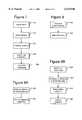
- FIGS. 3A-3Cillustrate sample graphics for reporting the vertical position of an object.
- FIG. 4illustrates an exemplar graphical user interface for the present invention.
- FIG. 5is a flow chart illustrating the method for recording data.
- FIG. 6is a flow chart illustrating the method for determining a vertical position.
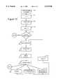
- FIG. 7is a flow chart illustrating the method for camera mapping.
- FIG. 8is a flow chart illustrating the method of registering a camera.
- FIG. 9Ais a flow chart illustrating a first method for determining the location of a camera.
- FIG. 9Bis a flow chart illustrating a second method for determining the location of a camera.
- FIG. 10is a flow chart illustrating a method for minimizing registration error.
- the present inventioncan be used in conjunction with many different events and situations, including sporting events and events other than sporting events.
- sporting events and events other than sporting eventsFor illustrative purposes, the embodiment described below is used in conjunction with the broadcast of a basketball game.
- FIG. 1depicts a basketball court 10.
- Basketball court 10includes a rim, net, backboard and support for the backboard (collectively called a "basket") at locations 14 and 16.
- the baskets at locations 14 and 16are not shown in FIG. 1 for ease of illustration.
- the present inventioncan be used with various types of sensors. For example, it is known in the art to track objects using video cameras, infrared sensors, ultraviolet sensors, x-ray sensors, radar sensors, ultrasound sensors, sonar sensors, etc.
- the particular embodiment disclosed belowuses video cameras as sensors.
- the output of a video camerais a signal that represents a video image.
- Other sensorsoutput different types of signals, many of which can represent an image.
- One example of a suitable video camerais the DXC-151A CCD Color Video Camera from Sony Corporation.
- the present inventionis not limited to the particular Sony camera and any other suitable video camera can be used.
- FIG. 1shows four video cameras 20, 22, 24 and 26.
- Video cameras 20 and 22are primary cameras.
- Video cameras 24 and 26are secondary cameras.
- Video camera 20is mounted at location 14 and is pointed toward the basket at location 16.
- Video camera 22is mounted at location 16 and points toward the basket at location 20.
- video cameras 20 and 22are mounted approximately 12 feet off the floor, although other heights may also be suitable (e.g. 9 ft.).
- Video cameras 20 and 22can be mounted on the support structure that holds the backboard (e.g. behind the backboard) or on a separate structure.
- Video cameras 20 and 22are mounted parallel (or close to parallel) to the floor surface.
- Camera 26is mounted in the arena near the center line of the basketball court and points toward the basket at location 16.
- Camera 24is also mounted in the arena near the center line of the basketball court; however, camera 24 points toward the basket at location 14.
- cameras 24 and 26are mounted at the same location as the main broadcast cameras for the television broadcaster.
- cameras 24 and 26can be located in areas other than near the center line, as long as the cameras can view the baskets.
- Cameras 22 and 24are considered to be a left camera pair because both cameras point toward the basket at location 14 (on the left hand side of the court from the viewpoint of the main broadcast camera).
- Cameras 20 and 26are considered to be a right camera pair because both cameras are pointing toward the basket at location 16 (on the right hand side of the court from the viewpoint of the main broadcast camera).
- FIG. 1only shows one set of suitable sensor locations. Other locations for placing the sensors may also be used with the present invention.
- FIG. 2is a block diagram of one example of a hardware system used to implement the present invention.
- the components shown in FIG. 2may reside in a truck in a parking lot outside an arena, in a video production room inside the arena or any other suitable location.
- a video switch 60receives a video signal from each of the cameras shown in FIG. 1.
- video switch 60receives a signal from camera 20, from camera 22, from camera 24 and camera 26.
- Video switch 60chooses either the left camera pair or the right camera pair. That is, either the signal from camera 20 or from camera 22 will be passed on to signal 63, and the corresponding signal from either camera 24 or camera 26 will be passed to output signal 61.
- camera 20is selected
- camera 26is also selected.
- camera 22is selected
- camera 24is also selected.
- Video switch 60can switch the inputs on command from a computer, other hardware or a manual switch.
- a human operator watching the gamewill choose either the left camera pair or the right camera pair based on the play of the game. If a player is about to dunk a basketball into the basket at location 16, the operator would choose the right camera pair. If a player is about to dunk a basketball into the basket at location 14, the operator would choose the left camera pair.
- Computer 62includes a processor, a memory, a disk drive, input devices and output devices (including a monitor).
- computer 62is an O2 Workstation from Silicon Graphics, Inc. Although the O2 is used in the embodiment of FIG. 2, various other computers and processors are also suitable for the present invention.
- Computer 62includes an analog video input and digital video input.
- Line 63is an analog video signal from video switch 60 to the analog video input of computer 62.
- the signal on line 61is an analog video signal that is sent to analog to digital convertor 64.
- An example of a suitable analog to digital convertoris the ASD-251u NTSC/PAL to 4:2:2 Decoder from Miranda Technologies, Inc., Quebec, Canada; however, other converters may also be suitable for the present invention.
- the output of analog to digital convertor 64is sent to video port interface 66.
- the output of video port interface 66is sent to the digital input of computer 62.
- Video port interface 66translates the digital video signal into a proprietary digital format suitable for input into computer 62.
- An example of a suitable video port interfaceincludes the VIVO 4:2:2 Video Port Interface for the SGI O2 workstation, from Miranda Technologies, Inc.
- computer 62will include two analog video inputs and, thus, there is no need for analog to digital convertor 64 or video port interface 66.
- computer 62will include two digital inputs, requiring both input signals to be converted to digital signals prior to computer 62.
- Computer 62also receives inputs from time code readers 68 and 70.
- Time code reader 68receives its input from the master time code generator.
- Time code reader 70receives its input from replay unit 72, which (in one embodiment) is a standard replay deck known in the art.
- the output of computer 62is sent to graphics generator 74.
- Computer 62determines the vertical position of the object of interest.
- Computer 62sends the vertical position information to graphics generator 74, which creates a graphic for displaying the vertical position information.
- Graphics generator 74can be any hardware and/or software that can generate a graphic based on input information.
- a suitable graphics generatoris a MAXINE! from Chyron Corporation.
- An alternative graphics generatorcould include a computer or other hardware/software that is capable of generating a graphic.
- the input to graphics generator 74is ASCII text.
- the output of graphics generator 74includes 2 signals 76 and 78, both of which are sent to a video modification unit 80.
- computer 62generates the graphic.
- the systemreports the vertical position information without creating a graphic.
- Video modification unit 80modifies the video signal received from replay unit 72 with a video signal (or graphic) sent by graphics generator 74.
- the type of modificationcan vary depending on the desired graphic.
- One embodimentutilizes a keyer as a video modification unit.
- the signals from graphics generator 74include a video signal 76 and an alpha (or key) signal 78.
- Video signal 76is called foreground and the signal received from replay deck 72 is called background.
- the keyerdetermines how much of the foreground and background to mix to determine the output signal from 100% foreground and 0% background to 0% foreground and 100% background, on a pixel by pixel basis.
- video modification unit 80can be performed by computer 62 or a separate computer. In another embodiment, the functions of video modification unit 80 can be performed by graphics generator 74. That is, the output of computer 62 and the output of replay deck 72 are sent to graphics generator 74, which creates a graphic for conveying the vertical position and adds that graphic to the video from replay deck 72.
- Non-video datais information other than traditional data used by a television to draw the normal scan lines on a television display.
- An example of non-video datais information that is transmitted during the vertical blanking interval, which can be closed caption data, statistics, interactive queries or Internet addresses.
- FIGS. 3A, 3B and 3Cdepict three examples of suitable graphics for use with the present invention. These graphics are shown for example purposes only and many other different graphics can used. The specific format of the graphic is not important to the present invention.
- FIG. 3Ashows a rectangular graphic having 2 fields. Field 102 conveys the vertical position of the object and field 104 can be an advertisement or other information.
- FIG. 3Bshows vertical bar 112 and pointer 114. Vertical bar 112 includes a preselected set of vertical position numbers. Pointer 114 is moved up and down vertical bar 112 until it points to the appropriate position on the vertical bar 112 representing the actual vertical position. Pointer 114 will also display the actual vertical position.
- FIG. 3Cshows a semicircular bar 122 illustrating various preselected vertical position numbers.
- Arrow 124points to the place on semicircular bar 122 that represents the actual vertical position.
- the systemadd a window in the corner of the screen which shows the player jumping (e.g. at the top of his jump), a bar indicating the top of the player's head, an arrow from the floor to the bar and a numerical display of the magnitude of the vertical leap.
- Alternative graphicscan also show the player's name, number, height and other statistics.
- computer 62will send information of the actual vertical position to graphics generator 74.
- Graphics generator 74will create a graphic (one of the graphics of FIGS. 3A-3C or another graphic) and video modification unit 80 adds the graphic to the video signal from replay unit 72.
- the graphic conveying the height of a player's jumpis added to a replay (e.g. instant replay).
- the graphiccan be stored for later use or added to live video by connecting video modification unit 80 to a live video feed (e.g. from a broadcast camera).
- the vertical positioncan be reported to a commentator using a monitor, other display, printer, speaker, or other output device.
- Computer 62includes a monitor and one or more input devices. Examples of suitable input devices include a keyboard and a pointing device (e.g. a mouse, pen, trackball, etc.).
- FIG. 4depicts one example of suitable graphical user interface (GUI) 160 to be used in conjunction with the monitor and input devices of computer 62.
- GUI 160includes a window 162 which displays the video signal from the selected primary camera that was sent on line 63 and stored in computer 62.
- Window 164displays the video signal from the selected secondary camera which was received from video port interface 66 and stored by computer 62.
- GUI 160also includes 4 buttons: record button 170, compute left button 172L, compute right button 172R and register button 174. Selecting record button 170 instructs the system to operate in record mode. Selecting compute left button 172L or compute right button 172R instructs the system to operate in compute mode. Selecting register button 174 instructs the system to operate in registration mode. Record mode, computer mode and registration mode are all discussed in more detail below.
- the systemdetermines the three dimensional location of the top of a basketball player's head at the top of the player's jump. The system then subtracts the height of the player from the height of the top of the player's head to determine the height from the ground that the player jumped. The system displays the player's name in field 180 and the height of the player's jump in field 182 of GUI 160. The operator can view both values and, if satisfied, the operator can select send button 184 to send the height information to a queue. The height information sits in the queue until computer 62 receives the appropriate time code from replay deck 72, at which time it is sent to graphics generator 74.
- the appropriate time codeis the time code corresponding to the frame of video used to determine the vertical position minus a user selected offset (e.g. three seconds).
- Field 166 on graphic user interface 160is a slider that can be used to select the frame of video that is shown in fields 162 and 164 (synchronized using time codes) from those frames of video stored in computer 62.
- the slideris in a vertical orientation, adjacent to fields 162 and 164, and is of a length that spans from the bottom of field 164 to the to of field 162.
- other software buttons, a shuttle or another hardware apparatuscan be used to select the particular frame of video.
- Player list 190 on GUI 160lists all the players and their heights. A particular player can be selected from list 190 and deleted using DEL button 196. A new player can be added to list 190 by adding the new information into edit box 194 and selecting add button 192.
- FIG. 5is a flow chart illustrating the method for recording data after record button 170 of GUI 160 is selected.
- the systemcaptures video using the cameras discussed above.
- the video signals from the selected camerasare sent to computer 62.
- Video switch 60can be switched between the left camera pair and the right camera pair.
- the source of that video(which camera captured the video) is also recorded.
- the videois digitized.
- Video from the selected secondary camerais digitized using analog to digital convertor 64.
- the video signal from the selected primary camerais digitized in computer 62.
- the video informationis eventually stored by computer 62 in RAM, on a disk or on another storage medium.
- the video datais stored in a loop buffer.
- step 254the system determines whether the loop buffer is full. In one embodiment, the loop buffer can only hold 30 seconds of video for the primary camera and 30 seconds of video for the secondary camera. If the loop buffer is not full, the system stores the captured video (step 258). If the loop buffer is full, the system writes the new video over the oldest video data (step 256).
- the O2 workstation in the system discussed abovecan not reliably store data in a suitable format at 30 frames per second, which is approximately the rate of output of the cameras noted above. Thus, every third frame is dropped so that the O2 stores only twenty frames per second.
- Each of the video signals selected by video switch 60is compressed using JPEG compression prior to storage in the loop buffer.
- the frames of video that are storedare time coded. The time code can be written for each frame or written once every n frames. The time codes can be stored in the data for the frames of video or in a separate data structure.
- step 256 or step 258the system loops back to step 250 and more video is captured.
- the steps of FIG. 5are not necessarily performed in the order shown in FIG. 5.
- the systemis constantly capturing video and does not stop capturing video in order to perform steps 252-258.
- the method of FIG. 5is continuously performed while the system is in record mode. When an operator selects either button 172 or 174, the system stops performing the steps of FIG. 5.
- the primary and secondary video signals received by computer 62are not completely symmetrical. That is, a signal sent by video switch 60 on line 61 is processed by analog to digital convertor 64 and video port interface 66; therefore, it takes longer for the video signal selected from the secondary camera to reach computer 62, as compared to the video signal from the selected primary camera.
- One method for figuring out the difference in timing of the two signalsis to concurrently point the primary and secondary cameras at the same spinning wheel and note the number of frames that the two signals are out of synchronization. Once the difference in timing is known, computer 62 can compensate accordingly by aligning the appropriate frames of video. In one embodiment, computer 62 can be programmed to determine the difference in timing.
- a camera paircan be replaced by a set of three or more sensors.
- Computer 62should be able to store images for each sensor selected.
- some of the processing done by computer 62can be performed by another processor local to one or more cameras.
- Another embodimentmay use more than two groups of sensors and video switch 60 will be used to choose one of the groups.
- FIG. 6is a flow chart of one example of a method for determining a vertical position of the object.
- step 300a frame of video from the primary camera that is stored in computer 62 is identified for which the vertical position will be calculated from.
- the frame of video identifiedshould be the frame where the player is at the top of his or her jump.
- the operatoruses slider 166 to shuttle between all the frames of video stored for the primary camera. As the operator is moving slider 166, the different frames are appearing in window 162. The operator shuttles between the frames until the operator sees the player at the top of his or her jump. At that point, the operator stops and has identified the frame to be used for the computation.
- the systemcan include pattern recognition software to find the player jumping and determine when the player has reached the top of the player's jump and/or identify an appropriate frame of video.
- the position of the object in the identified frame of videois determined in step 302.
- the operatoruses a pointing device (e.g. a mouse), in window 162, to point to the top of the player's head.
- the operatorcan point to other parts of the object.
- An alternativecan include using pattern recognition software to perform this step automatically.
- step 304the position of the object in the frame of video for the secondary camera is determined. Because each frame of video is time coded, when the frame from the primary camera is selected in step 300 a corresponding frame from the secondary camera can be selected by the computer 62 automatically and displayed in window 164. In an alternative embodiment, a frame of video can be identified for the secondary camera in the same manner that step 300 is performed. After identifying the frame of video for the secondary camera, the operator uses the pointing device to select the top of the player's head in the identified frame of video from the secondary camera.
- the systemcan determine a line of position from the primary video camera to the point selected by the operator in step 302 and then display that line in window 164.
- Computer 62can restrict the operator such that the operator can only select a position in window 164 that is on the displayed line.
- step 304can be performed automatically using pattern recognition software.
- the systemdetermines a vector from the primary camera to the object (step 306).
- This vectoris also called a line of position and runs from the camera through the object.
- the vectoris determined by using a pixel map.
- each of the cameras 20, 22, 24 and 26utilizes one or more charge coupled devices (CCD).
- CCDcharge coupled devices
- the CCDthe sensing element of the camera, is broken up into a number of pixels.
- the systemPrior to operation of the system of FIG. 2, the system is loaded with a pixel map for each sensor.
- the pixel mapis a set of data or a set of equations which can be used to determine a vector in a camera based coordinate system, for any pixel (or sub-pixel) on the CCD.
- the camera based coordinate systemis defined by locating the origin at the front nodal point of the camera lens.
- the X axis, Y axis and Z axisare defined as follows: when standing behind the camera and looking in the same direction the camera is pointed, the X-axis points to the right, the Y-axis points up and the Z-axis points straight back through the camera itself. Each axis is perpendicular to the other two.
- the vectors defined by the pixel maporiginate from the nodal point.
- a target board with a grid of pointsis mounted on a wall or other support structure. Each point in the grid is four inches from its neighbor.
- the camera(or other sensor) is mounted and aimed at the target board.
- the camerashould be mounted such that the board fills the camera's field of view, the camera's optical axis is perpendicular to the target board and the camera's optical axis passes through the center point of the board.
- the camerais also aligned such that the camera's CCDs are parallel, to the extent possible, to the board.
- step 354the distance from the camera's front nodal point to the target board is measured.
- the camera's outputis sent to a computer with a monitor and a pointing device.
- step 356a user points (using the pointing device) on the monitor to each point on the target board.
- the computerstores the pixel coordinates and real vector.
- the real vectoris the actual vector from the camera to the point on the board, which can be determined by direct measurement.
- the real vectorexpressed in the camera's coordinate system, has the X coordinate equal to the horizontal distance the point is from center of the board, the Y coordinate equal to the vertical distance the point is from the center of the board and the Z coordinate equal to the negative of the distance from the camera's front nodal point to the center of the board.
- real.x and real.yare the x and y values of the real vectors
- ccd.xis the x coordinate of the pixel for the point on the board associated with the particular real vector
- ccd.yis the y coordinate of the pixel for the point on the board associated with the particular real vector
- the coefficients A1 through H1 and A2 through H2are determined by minimizing the sum of the squared errors, where each error is the difference between the value for real.x, real.y or real.z computed with the equations above and the corresponding known coordinates for each point on the board.
- One embodimentcomputes the values of the coefficients using multiple linear regression, for example, using the LINEST function in Excel by Microsoft Corporation;
- ccd.radis the "pixel radius", or radius from the center of the CCD array to the pixel of interest;
- ccd.rad2is the square of ccd.rad.
- ccd.rad4is the fourth power of ccd.rad.
- variable ccd.radis computed as follows:
- pix.centerxis the x coordinate of the center of the CCD (in pixels)
- pix.centeryis the y coordinate of the center of the CCD (in pixels)
- step 306includes using the x and y coordinates of the pixel pointed to by the user in step 302 as ccd.x and ccd.y in the equations for real.x and real.y.
- the vector normalized-realis then used in future steps of the method described in FIG. 6.
- step 308the vector for the secondary camera is determined in the same manner used for step 306. That is, the x and y coordinates for the pixel selected in step 304 are plugged into the equation to determine real.x and real.y. The real vector is then normalized. At this point, the system now has two vectors (in respective camera coordinate systems), one vector represents a straight line from the primary camera through the top of the player's head and the second vector represents a straight line from the secondary camera through the top of the player's head.
- both vectorsare transformed from respective camera based coordinate systems to an arena based coordinate system.
- a coordinate systemwas set up for each camera. Each camera will have its own coordinate system, thus, the vectors from the different cameras are incompatible with each other. To make the vectors compatible they must be transformed to the same coordinate system. Therefore, a new coordinate system is set up called the arena coordinate system.
- the arena coordinate systemis set by placing the origin in the corner of the basketball court. Looking back at FIG. 1, point 30 indicates the origin.
- the positive X axisis along the out-of-bounds lines 34.
- the positive Y axisis along out-of-bounds line 32.
- the positive Z axiscomes straight up from the court and is perpendicular to both the X axis and Y axis.
- Other definitions of an arena coordinate systemmay also be used.
- a transformation matrixis a direction-cosine matrix.
- the direction-cosine matrixis a 3 ⁇ 3 matrix which defines one coordinate system relative to another.
- the direction-cosine matrixincludes information about the orientation of the sensor. Orientation includes information about pan, tilt and roll. Registration parameters are defined to include orientation information, location information, zoom information, lens distortion, other parameters that describe the physics of the sensor, and/or a subset of the above listed information.
- step 310includes computer 62 multiplying the vectors found in steps 306 and 308 by their respective direction-cosine matrices.
- the direction-cosine matrixis discussed in more detail below. Other methods of transforming the vectors can also be used with the present invention.
- step 310the system has two vectors in the same coordinate system. Each vector starts from its respective camera and travels through the object. In an ideal world, the two vectors would intersect at the object. However, due to real world limitations, the two vectors are not likely to actually intersect. Thus, in step 312 computer 162 determines the point of closest approach. In one sense, the point of closest approach can be thought of as the point where the two vectors are the closest to each other. Since the two vectors do not intersect, there will be a point of closest approach for each vector. Computer 62 will use the point of closest approach along the vector from the primary camera. The point of closest approach is found on the vector from the primary camera as follows:
- pnt1is the point (pnt1.x, pnt1.y, pnt1.z) of closest approach on the vector emanating from the primary camera;
- pt1is the location (py1.x, pt1.y, pt1.z) of the primary camera itself (and thus the origin of the vector from the primary camera);
- sis the distance along the vector emanating from the primary camera to the point of closest approach
- vec1is the vector (expressed in arena coordinates) from the primary camera transformed in step 310;
- Matrix Ais a 3 ⁇ 3 matrix whose rows are diff -- 1 -- 2, vec2, and cross -- 12.
- the variable sis computed by taking the determinant of the matrix A divided by the dot product of cross -- 12 with itself,
- diff -- 1 -- 2is the vector obtained by subtracting vec1 from vec2;
- vec2is the vector (expressed in arena coordinates) from the secondary camera transformed in step 310;
- cross -- 12is the vector obtained by taking the cross product of vec1 with vec2.
- step 314computer 62 determines the vertical position of the object.
- the point of closest approach determined in step 312represents the three dimensional location of the top of the player's head at the peak of his or her jump.
- the three dimensional locationincludes an x coordinate, a y coordinate and a z coordinate.
- the z coordinate, pnt1.zis the vertical position of the top of the players head in relation to the surface of the floor.
- Computer 62subtracts the player's height from pnt1.z to determine the height of the players jump, which in the present example is the desired vertical position of the object. Thus, if the top of the players head is 9 feet from the floor and the player is 6 feet, 6 inches tall, then the height of the players jump is 30 inches.
- Computer 62transmits the height of the jump (one example of vertical position data) to graphics generator 74.
- graphics generator 74generates a graphic, as discussed above.
- video modification unit 80adds the generated graphic to the video from replay unit 72. The video with the graphic can then be recorded or broadcast.
- the systemwill be in record mode most of the game.
- a produceror someone else sees a slam dunk (or other play) for which the producer would like the height of the player jumping
- the operatorwill put the system in compute mode and computer 62 will compute the height of the player's jump.
- the graphic displaying the height of the player's jumpcan be inserted into live video (rather than from a replay unit) or the broadcaster can choose to add the graphic to an instant replay (from replay unit 72) of the dunk.
- Registrationis a process of defining how to interpret data from a sensor (a camera being one type of sensor).
- the sensors described aboveoutput data, for example, which is used to determine position or location. Since position or location is relative, the system needs a reference from which to interpret the data and determine position or location.
- One example of how to interpret the data from different sensorsis to use the direction-cosine matrices described above.
- defining how to interpret dataincludes determining the direction-cosine matrices for each sensor.
- FIG. 8is a flow chart illustrating the steps of registering a camera (or other sensor) for the present invention. The steps of FIG. 8 should be performed prior to using the system in record mode or compute mode.
- step 400the location of the camera is determined.
- step 402the location of the camera is used to determine the direction-cosine matrix for each camera. Each of these steps will be discussed in more detail below.
- FIG. 9Ais a flow chart illustrating a first method for determining the location of a camera (step 400 in FIG. 8).
- Step 500includes measuring the distance from the camera to three known fiducials.
- a fiducialis a reference mark and a known fiducial is a reference mark whose location is known.
- One method for measuring these distancesis to use a laser range finder. Alternatively, a tape measure can be used.
- Step 502includes solving for the following 3 equations:
- the coordinates (pos.x, pos.y and pos.z )is the position of the sensor we're solving for.
- Vec1is coordinates of the first fiducial expressed in arena coordinates. Note that vec1 includes three coordinates (vec1.x, vec1.y, vec1.z).
- vec2 and vec3give the coordinates of the 2nd and 3rd fiducials, respectively, in arena coordinates.
- the values of x, y, & zare obtained as follows:
- d1sq, d2sq and d3 sqare the squares of the measured distances from the camera position to the first fiducial, the second fiducial and the third fiducial, respectively,
- FIG. 9Bis a flow chart of a second method for determining the location of a camera.
- Step 600includes determining the height of the camera. This can be accomplished by measuring the height of the camera directly using a tape measure or a laser range finder.
- Step 602includes measuring the x and y distances to a set of two known fiducials.
- One embodiment of performing step 602includes measuring the distance from a point directly below the camera to two known fiducials on the court surface. To determine the point directly below the camera, a plumb bob can be hung from the camera and stickers placed on the court below the plumb bob. Using a laser range finder, tape measure or any other suitable method, the distance from the sticker to the two known fiducials can be measured.
- step 604the following equations are used to find two possible solutions (xa, ya) and (xb, yb) for the location of the camera:
- dist1is the measured distance from the sticker below the camera to the first fiducial
- dist2is the measured distance from the sticker below the camera to the second fiducial
- alpha1arc-cosine((dist1*dist1-dist2*dist2+d*d)/(2.0*dist1*d))
- alpha2arc-tangent2(dy, dx)
- Step 402 of FIG. 8includes determining the direction-cosine matrix for a camera.
- the direction-cosine matrixrepresents(or embodies) the orientation of the camera.
- the direction-cosine matrixis determined by first determining two temporary matrices. The first temporary matrix transforms a vector from a camera coordinate system to a temporary coordinate system. The second matrix converts the vector from the temporary coordinate system into the arena coordinate system. The two matrices can be reduced to a single matrix by multiplying the two matrixes together to form a single 3 ⁇ 3 matrix.
- the direction-cosine matrixis computed using the following equation:
- dc -- scis the 3 ⁇ 3 direction-cosine matrix which converts a vector in the camera coordinate system into the same vector expressed in the arena coordinate system;
- dc -- tcis the 3 ⁇ 3 which converts a vector in the temporary coordinate system into the same vector expressed in arena coordinate system;
- dc -- stis the 3 ⁇ 3 matrix which converts a vector in the camera coordinate system into the same vector expressed in the temporary coordinate system.
- vectDfiducial-2-camera.pos
- vectCcross-product of vectA with vectD (normalized)
- vectBcross-product of vectC with vectA
- fiducial-1 and fiducial-2are the three-dimensional coordinates of the two known fiducials in the arena coordinate system.
- dc -- stis defined as: ##EQU2## where: vectF is the normalized vector, in the camera coordinate system, corresponding to the pixel position of fiducial-1 in the camera's field of view obtained from the pixel map described above;
- vectKis the normalized vector, in the camera coordinate system, corresponding to the pixel position of fiducial-2 in the camera's field of view, obtained from the pixel map described above;
- vectHis the cross-product of vectF with vectK (normalized).
- vectGis the cross-product of vectH with vectF.
- the total error objective functionis defined as a function of the differences between the calculated vertical positions of a set of fiducials and the actual known vertical positions.
- a typical objective functionis the sum of squares of the errors.
- the registration parameters subject to adjustmentare the camera locations, a breathing factor for each camera and orientation for each camera.
- the breathing factoris a scale factor corresponding to focus applied to camera focal length. Many methods for accomplishing such optimization are known.
- One that is related to the method used in the current inventionis Tsai's Camera Calibration.
- FIG. 10is a flow chart which explains one method of adjusting system parameters to minimize error.
- Step 702comprises determining the initial parameters, which includes any or all of the methods described above for determining a pair (left pair or right pair) of camera locations, lens maps and direction cosine matrices.
- a counting index (i)is initialized to zero.
- the erroris computes using the initial parameters.
- the erroris determined by using the system to calculate the height of each known fiducial, comparing those heights to the known actual heights and calculating the total error objective function.
- the gainis initially set to four (other initial values can also be used).
- step 710the method of FIG. 10 is done. In one embodiment, the error is small enough if all calculated heights are within 3/4 of an inch of actual heights. If the error is not small enough, the parameters are adjusted in step 712.
- the location parametersare adjusted by adding to or subtracting from the parameter the product of the gain multiplied by a preset increment. For example, preset increment for the the position coordinates can be 0.01 meters.
- the breathing factoris adjusted by adding to or subtracting from real.z the product of the gain multiplied by a preset increment. The preset increment for the breathing factor can be 0.01 meters.
- the orientationis adjusted by multiplying the direction-cosine matrix by another matrix or (matrices) that represent(s) an adjustment in pan, tilt and/or roll, the adjustment being equal to the product of the gain multiplied by a preset increment.
- the preset increment for the orientationcan be 0.01 degree changes in pan, tilt and roll.
- step 714the total error objective function is recalculated using the newly adjusted parameters.
- This newly calculated error (e i+1 ) and the previously calculated error ( ei )are displayed to an operator in step 716.
- the operatorhas four choices based on comparing e i+1 to e i , : end the process, continue (step 720), increase the gain by 1.5 and continue (step 722), or decrease the gain by 0.5 and continue (step 724). If e i+1 is small enough or the operator does not believe it would be efficient to continue, then the operator should choose (but is not required) to end the method of FIG. 10. Otherwise, the operator has to make a judgement based on experience whether to choose steps 720, 722 or 724. After steps 720, 722 or 724, the system increments the index i in step 726 and loops back to step 712.
- the above described systemrequires a least two sensors to determine the vertical position of an object. That is, the system can function with only one camera pair.
- An alternative embodimentcan determine a vertical position with only one sensor. Looking at FIG. 1, the system can be set up with either sensor 20, sensor 22 or both. If the system has both sensors, only one sensor is selected at any given time (depending on which side the basketball is on). Using one sensor, the system can determine a vector from the sensor to the top of the players head. Because there is not a second vector to resolve where along the first vector the object actually is, the system can make an estimate of that point. That is, it can be assumed that all dunks are performed utilizing a jump that peaks at approximately 5 feet from the basket.
- the systemcan determine the point on the vector which is the appropriate distance from the sensor and use the point as the point of closest approach. The system would still perform the steps of 300, 302, 306 and 310. Steps 304 and 308 would be skipped. Step 312 will be performed by finding the point along the vector that is 5 feet from the basket. Steps 314-318 would be performed as discussed above.
- the systemcan use one camera which has a variable zoom lens.
- the variable zoom lenshas at least two settings, one for when the ball is in the far court and one for when the ball is in the near court.
- Another embodiment of the present inventionincludes two cameras and two video tape machines.
- the videodoes not need to be digitized.
- the operatorcan use the forward and reverse controls on the video tape machine to find the frame where the player is at the top of the player's jump.
- the images from the video tape playercan be displayed on a television monitor.
- the operatorcan measure, using a ruler or other device, the position of the player's head on the monitor's screen. That measured position can be used to determine the height of the jump with or without using a computer.
- the video tape machinecan be eliminated by having the operator watch the game on a television monitor and when a player jumps, the operator simply places his/her finger (or other pointing device) on the location of the top of the player's head at the top of the jump.
- One method for calculating the height of a jump based on a location on a monitor's screen or based on pixel coordinatesis to use a look up table.
- the input to the look up tablecan be the x and y coordinates from one or more of the cameras and the output of the look up table can be a three dimensional location or a vertical position.
- One way to create such a look up tableis to use a set of poles. Each pole being at a different, but known, height. The poles are placed in and moved around the field of view for each camera. The pixels or screen position are recorded for each pole and used to create the map. For pixels or positions that do not correspond to a pole, the system can interpolate.
- the systemcan determined the hang time for a jump based on the time code stored with the video images.
- Hang timecan be defined as the time an object is airborne, the time an object is within a percentage of the peak of its trajectory, or another appropriate time.
- a userwould select the frame of video to start the hang time computation and a frame of video to end the hang time computation. By looking at the difference between the time codes for both frames, the system can determine the hang time.
- the systemcan be used to add a graphic to the live video after the jump.
- a graphicis to add a window to the corner of the screen which shows the player jumping.
- the imagecould be from a broadcast camera or it can be the selected frame(s) from either the primary camera or secondary camera discussed above.
- the systemwould add a graphic to the image of the player jumping which indicates the height of the jump.
- the present inventioncan be used with NTSC, PAL, SECAM, SDTV, DTV, HDTV or other video formats.
Landscapes
- Physics & Mathematics (AREA)
- General Physics & Mathematics (AREA)
- Engineering & Computer Science (AREA)
- Computer Vision & Pattern Recognition (AREA)
- Theoretical Computer Science (AREA)
- Image Analysis (AREA)
- Length Measuring Devices By Optical Means (AREA)
Abstract
Description
real.x=A1*ccd.x+B1*ccd.y+C1*ccd.x*ccd.x+D1*ccd.y*ccd.y+E1*ccd.x*ccd.y+F1*ccd.rad2+G1*ccd.rad4+H1
real.y=A2*ccd.x+B2*ccd.y+C2*ccd.x*ccd.x+D2*ccd.y*ccd.y+E2*ccd.x*ccd.y+F2*ccd.rad2+G2*ccd.rad4+H2
real.z=-(measured distance to target board)
dx=ccd.x-pix.centerx
dy=ccd.y-pix.centery
ccd.rad=√(dx*dx+dy*dy)
length=√(real.x*real.x+real.y*real.y+real.z*real.z)
normalized-real.x=real.x/length
normalized-real.y=real.y/length
normalized-real.z=real.z/length
pnt1.x=pt1.x+s*vec1.x
pnt1.y=pt1.y+s*vec1.y
pnt1.z=pt1.z+s*vec1.z
pos.x=x+vec1.x
pos.y=y+vec1.y
pos.z=z+vec1.z
xa=x1+dist1*cos(alpha2+alpha1)
ya=y1+dist1*sin(alpha2+alpha1)
xb=x1+dist1*cos(alpha2-alpha1)
yb=y1+dist1*sin(alpha2-alpha1)
dc.sub.-- sc=dc.sub.-- tc*dc.sub.-- st
Claims (46)
Priority Applications (4)
| Application Number | Priority Date | Filing Date | Title |
|---|---|---|---|
| US09/041,238US6133946A (en) | 1998-01-06 | 1998-03-11 | System for determining the position of an object |
| AU22041/99AAU2204199A (en) | 1998-01-06 | 1998-12-23 | System for determining the position of an object |
| EP98966055AEP1046039A2 (en) | 1998-01-06 | 1998-12-23 | System for determining the position of an object |
| PCT/US1998/027377WO1999035503A2 (en) | 1998-01-06 | 1998-12-23 | System for determining the position of an object |
Applications Claiming Priority (2)
| Application Number | Priority Date | Filing Date | Title |
|---|---|---|---|
| US7059498P | 1998-01-06 | 1998-01-06 | |
| US09/041,238US6133946A (en) | 1998-01-06 | 1998-03-11 | System for determining the position of an object |
Publications (1)
| Publication Number | Publication Date |
|---|---|
| US6133946Atrue US6133946A (en) | 2000-10-17 |
Family
ID=26717939
Family Applications (1)
| Application Number | Title | Priority Date | Filing Date |
|---|---|---|---|
| US09/041,238Expired - LifetimeUS6133946A (en) | 1998-01-06 | 1998-03-11 | System for determining the position of an object |
Country Status (4)
| Country | Link |
|---|---|
| US (1) | US6133946A (en) |
| EP (1) | EP1046039A2 (en) |
| AU (1) | AU2204199A (en) |
| WO (1) | WO1999035503A2 (en) |
Cited By (92)
| Publication number | Priority date | Publication date | Assignee | Title |
|---|---|---|---|---|
| US20010016943A1 (en)* | 2000-01-31 | 2001-08-23 | Mike Maas | Method for detecting and identifying time-constant patterns in video signals of any video source, particularly for the detection of advertising spots in television broad-castings, and device for performing such a method |
| US6441846B1 (en)* | 1998-06-22 | 2002-08-27 | Lucent Technologies Inc. | Method and apparatus for deriving novel sports statistics from real time tracking of sporting events |
| US20020118969A1 (en)* | 2001-02-12 | 2002-08-29 | Takeo Kanade | System and method for stabilizing rotational images |
| US20020152476A1 (en)* | 1999-05-28 | 2002-10-17 | Anderson Tazwell L. | Audio/video programming and charging system and method |
| US20020194608A1 (en)* | 2001-04-26 | 2002-12-19 | Goldhor Richard S. | Method and apparatus for a playback enhancement system implementing a "Say Again" feature |
| WO2003011406A1 (en)* | 2001-07-30 | 2003-02-13 | Oy Virtual Advertising Systems Vas Ltd | A method for measuring the length of a sports performance |
| US20030073518A1 (en)* | 2001-09-12 | 2003-04-17 | Pillar Vision Corporation | Trajectory detection and feedback system |
| US20030091237A1 (en)* | 2001-11-13 | 2003-05-15 | Koninklijke Philips Electronics N.V. | Identification and evaluation of audience exposure to logos in a broadcast event |
| US6634967B2 (en)* | 2000-09-19 | 2003-10-21 | Benjamin S Daniel | Baseball umpiring system |
| US20030210329A1 (en)* | 2001-11-08 | 2003-11-13 | Aagaard Kenneth Joseph | Video system and methods for operating a video system |
| US20040005291A1 (en)* | 2001-10-12 | 2004-01-08 | Rogers Martha Karen Newell | Methods for regulating co-stimulatory molecule expression with reactive oxygen |
| US20040006424A1 (en)* | 2002-06-28 | 2004-01-08 | Joyce Glenn J. | Control system for tracking and targeting multiple autonomous objects |
| US20040032495A1 (en)* | 2000-10-26 | 2004-02-19 | Ortiz Luis M. | Providing multiple synchronized camera views for broadcast from a live venue activity to remote viewers |
| US6730926B2 (en) | 2001-09-05 | 2004-05-04 | Servo-Robot Inc. | Sensing head and apparatus for determining the position and orientation of a target object |
| US20040119819A1 (en)* | 2002-10-21 | 2004-06-24 | Sarnoff Corporation | Method and system for performing surveillance |
| US20040233288A1 (en)* | 2001-12-04 | 2004-11-25 | Mario Hytten | Computer-aided system for image production |
| US20050050575A1 (en)* | 2001-05-22 | 2005-03-03 | Marc Arseneau | Multi-video receiving method and apparatus |
| US20050074882A1 (en)* | 1998-04-17 | 2005-04-07 | University Of Vermont And State Agricultural College | Methods and products related to metabolic interactions in disease |
| US20050130772A1 (en)* | 2003-12-10 | 2005-06-16 | Avery Levy | Automated ball game training and playing system |
| US20050277466A1 (en)* | 2004-05-26 | 2005-12-15 | Playdata Systems, Inc. | Method and system for creating event data and making same available to be served |
| US20060146002A1 (en)* | 2005-01-06 | 2006-07-06 | Denso Corporation | Liquid crystal display device |
| US20060192852A1 (en)* | 2005-02-09 | 2006-08-31 | Sally Rosenthal | System, method, software arrangement and computer-accessible medium for providing audio and/or visual information |
| US7149549B1 (en) | 2000-10-26 | 2006-12-12 | Ortiz Luis M | Providing multiple perspectives for a venue activity through an electronic hand held device |
| US7193645B1 (en) | 2000-07-27 | 2007-03-20 | Pvi Virtual Media Services, Llc | Video system and method of operating a video system |
| US20070290499A1 (en)* | 2004-05-17 | 2007-12-20 | Tame Gavin R | Method and System for Creating an Identification Document |
| US20070293331A1 (en)* | 2004-05-26 | 2007-12-20 | Fredrik Tuxen | Method of and an Apparatus for Determining Information Relating to a Projectile, Such as a Golf Ball |
| US20080139330A1 (en)* | 2004-07-02 | 2008-06-12 | Fredrik Tuxen | Method and an Apparatus For Determining a Parameter of a Path of a Sports Ball on the Basis of a Launch Position Thereof |
| US20080182685A1 (en)* | 2001-09-12 | 2008-07-31 | Pillar Vision Corporation | Trajectory detection and feedback system for golf |
| US20080200287A1 (en)* | 2007-01-10 | 2008-08-21 | Pillar Vision Corporation | Trajectory detection and feedfack system for tennis |
| US20080219509A1 (en)* | 2007-03-05 | 2008-09-11 | White Marvin S | Tracking an object with multiple asynchronous cameras |
| US20080261711A1 (en)* | 2004-12-23 | 2008-10-23 | Fredrik Tuxen | Manners of Using a Sports Ball Parameter Determining Instrument |
| US20080312010A1 (en)* | 2007-05-24 | 2008-12-18 | Pillar Vision Corporation | Stereoscopic image capture with performance outcome prediction in sporting environments |
| US20090027501A1 (en)* | 2007-07-27 | 2009-01-29 | Sportvision, Inc. | Detecting an object in an image using camera registration data indexed to location or camera sensors |
| US20090075744A1 (en)* | 2005-03-03 | 2009-03-19 | Interactive Sports Games A/S | Determination of spin parameters of a sports ball |
| US7510710B2 (en) | 2004-01-08 | 2009-03-31 | The Regents Of The University Of Colorado | Compositions of UCP inhibitors, Fas antibody, a fatty acid metabolism inhibitor and/or a glucose metabolism inhibitor |
| US20090128577A1 (en)* | 2007-11-16 | 2009-05-21 | Sportvision, Inc. | Updating backround texture for virtual viewpoint animations |
| US20090128580A1 (en)* | 1999-10-21 | 2009-05-21 | Sportvision, Inc. | Telestrator System |
| US20090128568A1 (en)* | 2007-11-16 | 2009-05-21 | Sportvision, Inc. | Virtual viewpoint animation |
| US20090128549A1 (en)* | 2007-11-16 | 2009-05-21 | Sportvision, Inc. | Fading techniques for virtual viewpoint animations |
| US20090129630A1 (en)* | 2007-11-16 | 2009-05-21 | Sportvision, Inc. | 3d textured objects for virtual viewpoint animations |
| US20090128667A1 (en)* | 2007-11-16 | 2009-05-21 | Sportvision, Inc. | Line removal and object detection in an image |
| US20090182527A1 (en)* | 1999-12-23 | 2009-07-16 | Anoto Aktiebolag (Anoto Ab) | General information management system |
| US7593687B2 (en) | 2003-10-07 | 2009-09-22 | Immersion Entertainment, Llc | System and method for providing event spectators with audio/video signals pertaining to remote events |
| US20090295624A1 (en)* | 2004-07-02 | 2009-12-03 | Fredrik Tuxen | Method and apparatus for determining a deviation between an actual direction of a launched projectile and a predetermined direction |
| US20090326887A1 (en)* | 2008-06-27 | 2009-12-31 | Searete Llc, A Limited Liability Corporation Of The State Of Delaware | Wind profile systems for sporting applications |
| US20090326894A1 (en)* | 2008-06-27 | 2009-12-31 | Chan Alistair K | Methods of processing wind profile information in sports applications |
| US20090326823A1 (en)* | 2008-06-27 | 2009-12-31 | Chan Alistair K | Methods of using environmental conditions in sports applications |
| US20100077441A1 (en)* | 2005-07-22 | 2010-03-25 | Genevieve Thomas | Buffering content on a handheld electronic device |
| US7725073B2 (en) | 2002-10-07 | 2010-05-25 | Immersion Entertainment, Llc | System and method for providing event spectators with audio/video signals pertaining to remote events |
| US20100184534A1 (en)* | 2008-06-27 | 2010-07-22 | Searete Llc, A Limited Liability Corporation Of The State Of Delaware | Sports applications for wind profile systems |
| US7782363B2 (en) | 2000-06-27 | 2010-08-24 | Front Row Technologies, Llc | Providing multiple video perspectives of activities through a data network to a remote multimedia server for selective display by remote viewing audiences |
| US20100246955A1 (en)* | 2009-03-27 | 2010-09-30 | David Howell Wright | Methods and apparatus for identifying primary media content in a post-production media content presentation |
| US7812856B2 (en) | 2000-10-26 | 2010-10-12 | Front Row Technologies, Llc | Providing multiple perspectives of a venue activity to electronic wireless hand held devices |
| US7868914B2 (en) | 2004-06-07 | 2011-01-11 | Sportsmedia Technology Corporation | Video event statistic tracking system |
| US20110143868A1 (en)* | 2001-09-12 | 2011-06-16 | Pillar Vision, Inc. | Training devices for trajectory-based sports |
| US20110205022A1 (en)* | 2010-02-24 | 2011-08-25 | Cavallaro Richard H | Tracking system |
| US8051452B2 (en) | 2005-07-22 | 2011-11-01 | Kangaroo Media, Inc. | System and methods for enhancing the experience of spectators attending a live sporting event, with contextual information distribution capability |
| US8239910B2 (en) | 1999-03-08 | 2012-08-07 | Immersion Entertainment | Video/audio system and method enabling a user to select different views and sounds associated with an event |
| US8249299B1 (en)* | 2009-08-17 | 2012-08-21 | Adobe Systems Incorporated | Systems and methods of tracking objects in video |
| US8374423B2 (en) | 2009-12-18 | 2013-02-12 | Microsoft Corporation | Motion detection using depth images |
| US8408982B2 (en) | 2007-05-24 | 2013-04-02 | Pillar Vision, Inc. | Method and apparatus for video game simulations using motion capture |
| US8583027B2 (en) | 2000-10-26 | 2013-11-12 | Front Row Technologies, Llc | Methods and systems for authorizing computing devices for receipt of venue-based data based on the location of a user |
| US20130335545A1 (en)* | 2010-12-19 | 2013-12-19 | Matthew Ross Darling | System for integrated wound analysis |
| US8659663B2 (en) | 2010-12-22 | 2014-02-25 | Sportvision, Inc. | Video tracking of baseball players to determine the start and end of a half-inning |
| US20140085452A1 (en)* | 2011-03-18 | 2014-03-27 | Walter Nistico | Specacle Device With An Adjustable Field Of View And Method |
| US8908922B2 (en) | 2013-04-03 | 2014-12-09 | Pillar Vision, Inc. | True space tracking of axisymmetric object flight using diameter measurement |
| US9007463B2 (en) | 2010-12-22 | 2015-04-14 | Sportsvision, Inc. | Video tracking of baseball players which identifies merged participants based on participant roles |
| RU2559866C1 (en)* | 2014-05-14 | 2015-08-20 | Федеральное государственное бюджетное образовательное учреждение высшего профессионального образования "Российский государственный университет физической культуры, спорта, молодежи и туризма (ГЦОЛИФК)" (РГУФКСМиТ) | Device for measurement of range of horizontal jumps in track and field athletics |
| US9132352B1 (en)* | 2010-06-24 | 2015-09-15 | Gregory S. Rabin | Interactive system and method for rendering an object |
| US9146660B2 (en) | 2011-08-22 | 2015-09-29 | Trimble Navigation Limited | Multi-function affine tool for computer-aided design |
| US9300924B2 (en) | 1999-05-28 | 2016-03-29 | Immersion Entertainment, Llc. | Electronic handheld audio/video receiver and listening/viewing device |
| US9405433B1 (en)* | 2011-01-07 | 2016-08-02 | Trimble Navigation Limited | Editing element attributes of a design within the user interface view, and applications thereof |
| WO2016161047A1 (en) | 2015-04-02 | 2016-10-06 | Sportvision, Inc. | Automated framing and selective discard of parts of high resolution videos of large event space |
| WO2016168085A1 (en) | 2015-04-15 | 2016-10-20 | Sportvision, Inc. | Determining x,y,z,t biomechanics of moving actor with multiple cameras |
| US9641818B1 (en) | 2016-04-01 | 2017-05-02 | Adobe Systems Incorporated | Kinetic object removal from camera preview image |
| US9645235B2 (en) | 2005-03-03 | 2017-05-09 | Trackman A/S | Determination of spin parameters of a sports ball |
| US9646444B2 (en) | 2000-06-27 | 2017-05-09 | Mesa Digital, Llc | Electronic wireless hand held multimedia device |
| US9699438B2 (en) | 2010-07-02 | 2017-07-04 | Disney Enterprises, Inc. | 3D graphic insertion for live action stereoscopic video |
| US9697595B2 (en) | 2014-11-26 | 2017-07-04 | Adobe Systems Incorporated | Content aware fill based on similar images |
| US9754373B2 (en) | 2013-11-25 | 2017-09-05 | Gregory J. Seita | Methods and apparatus for automated bocce measurement and scoring |
| US9855481B2 (en) | 2009-01-29 | 2018-01-02 | Trackman A/S | Systems and methods for illustrating the flight of a projectile |
| US9955126B2 (en) | 2015-08-19 | 2018-04-24 | Rapsodo Pte. Ltd. | Systems and methods of analyzing moving objects |
| US9958527B2 (en) | 2011-12-16 | 2018-05-01 | Trackman A/S | Method and a sensor for determining a direction-of-arrival of impingent radiation |
| US10379214B2 (en) | 2016-07-11 | 2019-08-13 | Trackman A/S | Device, system and method for tracking multiple projectiles |
| US10393870B2 (en) | 2005-03-03 | 2019-08-27 | Trackman A/S | Determination of spin parameters of a sports ball |
| US10444339B2 (en) | 2016-10-31 | 2019-10-15 | Trackman A/S | Skid and roll tracking system |
| US10631044B2 (en) | 2009-12-31 | 2020-04-21 | The Nielsen Company (Us), Llc | Methods and apparatus to detect commercial advertisements associated with media presentations |
| US10834335B2 (en) | 2005-04-15 | 2020-11-10 | Freeze Frame, Llc | Interactive guest image capture using video wall/floor/ceiling displays for selections of background scenes, and selection/distribution of customized souvenir portfolios including merged images/sound |
| US10832055B2 (en) | 2018-01-31 | 2020-11-10 | Sportsmedia Technology Corporation | Systems and methods for providing video presentation and video analytics for live sporting events |
| US10989791B2 (en) | 2016-12-05 | 2021-04-27 | Trackman A/S | Device, system, and method for tracking an object using radar data and imager data |
| US10994172B2 (en) | 2016-03-08 | 2021-05-04 | Sportsmedia Technology Corporation | Systems and methods for integrated automated sports data collection and analytics platform |
| US11270415B2 (en) | 2019-08-22 | 2022-03-08 | Adobe Inc. | Image inpainting with geometric and photometric transformations |
Families Citing this family (4)
| Publication number | Priority date | Publication date | Assignee | Title |
|---|---|---|---|---|
| WO2000002102A1 (en)* | 1998-07-01 | 2000-01-13 | Sportvision System, Llc | System for measuring a jump |
| GB2379571A (en)* | 2001-09-11 | 2003-03-12 | Eitan Feldbau | Determining the Position of Players on a Sports Field |
| DE102004018288A1 (en)* | 2004-04-15 | 2005-11-03 | Conti Temic Microelectronic Gmbh | Approximate identification of object involves determining characteristics in defined region from graphic data in lines, columns or matrix form, determining numeric approximate value for object from graphic data by statistical classification |
| KR100841315B1 (en)* | 2006-02-16 | 2008-06-26 | 엘지전자 주식회사 | Broadcasting program information processing method using a mobile communication terminal and a data management server for processing broadcast program information, and a mobile communication terminal |
Citations (24)
| Publication number | Priority date | Publication date | Assignee | Title |
|---|---|---|---|---|
| US3580993A (en)* | 1968-09-27 | 1971-05-25 | Diebold Inc | Multiple camera superimposed message closed circuit television system |
| US3840699A (en)* | 1972-05-25 | 1974-10-08 | W Bowerman | Television system for enhancing and tracking an object |
| US4179704A (en)* | 1977-12-27 | 1979-12-18 | Cbs Inc. | Television system for displaying and recording paths of motion |
| US4521196A (en)* | 1981-06-12 | 1985-06-04 | Giravions Dorand | Method and apparatus for formation of a fictitious target in a training unit for aiming at targets |
| US4591897A (en)* | 1984-03-08 | 1986-05-27 | Edelson Steven D | System for generating a display of graphic objects over a video camera picture |
| US4700306A (en)* | 1981-06-24 | 1987-10-13 | Kungalvsgruppen Areng, Hjerpe, Wallmander Ab | System for the visualization of the movements of marine vessels by television display |
| US4839524A (en)* | 1986-12-29 | 1989-06-13 | Gte Products Corporation | Filter for isotopic alteration of mercury vapor |
| US4893182A (en)* | 1988-03-18 | 1990-01-09 | Micronyx, Inc. | Video tracking and display system |
| US4999709A (en)* | 1988-01-27 | 1991-03-12 | Sony Corporation | Apparatus for inserting title pictures |
| US5150895A (en)* | 1990-11-06 | 1992-09-29 | Richard Berger | Method of and system for determining a position of ball relative to a playing field, and ball provided therefor |
| US5179421A (en)* | 1990-08-20 | 1993-01-12 | Parkervision, Inc. | Remote tracking system particularly for moving picture cameras and method |
| US5264933A (en)* | 1991-07-19 | 1993-11-23 | Princeton Electronic Billboard, Inc. | Television displays having selected inserted indicia |
| US5268734A (en)* | 1990-05-31 | 1993-12-07 | Parkervision, Inc. | Remote tracking system for moving picture cameras and method |
| US5346210A (en)* | 1992-08-28 | 1994-09-13 | Teem Systems, Inc. | Object locator system |
| WO1995010919A1 (en)* | 1993-02-14 | 1995-04-20 | Orad, Inc. | Apparatus and method for detecting, identifying and incorporating advertisements in a video |
| WO1995010915A1 (en)* | 1993-10-12 | 1995-04-20 | Orad, Inc. | Sports event video |
| US5413345A (en)* | 1993-02-19 | 1995-05-09 | Nauck; George S. | Golf shot tracking and analysis system |
| US5419562A (en)* | 1993-08-10 | 1995-05-30 | Cromarty; John I. | Method and apparatus for analyzing movements of an individual |
| US5459793A (en)* | 1990-01-24 | 1995-10-17 | Fujitsu Limited | Motion analysis system |
| US5513854A (en)* | 1993-04-19 | 1996-05-07 | Daver; Gil J. G. | System used for real time acquistion of data pertaining to persons in motion |
| WO1997002699A1 (en)* | 1995-06-30 | 1997-01-23 | Fox Sports Productions, Inc. | A system for enhancing the television presentation of an object at a sporting event |
| US5675516A (en)* | 1995-09-27 | 1997-10-07 | Inex Vision Systems, Inc. | System and method for determining pushup of a molded glass container |
| US5724265A (en)* | 1995-12-12 | 1998-03-03 | Hutchings; Lawrence J. | System and method for measuring movement of objects |
| US5841441A (en)* | 1996-01-19 | 1998-11-24 | Virtus Corporation | High-speed three-dimensional texture mapping systems and methods |
- 1998
- 1998-03-11USUS09/041,238patent/US6133946A/ennot_activeExpired - Lifetime
- 1998-12-23EPEP98966055Apatent/EP1046039A2/ennot_activeWithdrawn
- 1998-12-23AUAU22041/99Apatent/AU2204199A/ennot_activeAbandoned
- 1998-12-23WOPCT/US1998/027377patent/WO1999035503A2/ennot_activeApplication Discontinuation
Patent Citations (24)
| Publication number | Priority date | Publication date | Assignee | Title |
|---|---|---|---|---|
| US3580993A (en)* | 1968-09-27 | 1971-05-25 | Diebold Inc | Multiple camera superimposed message closed circuit television system |
| US3840699A (en)* | 1972-05-25 | 1974-10-08 | W Bowerman | Television system for enhancing and tracking an object |
| US4179704A (en)* | 1977-12-27 | 1979-12-18 | Cbs Inc. | Television system for displaying and recording paths of motion |
| US4521196A (en)* | 1981-06-12 | 1985-06-04 | Giravions Dorand | Method and apparatus for formation of a fictitious target in a training unit for aiming at targets |
| US4700306A (en)* | 1981-06-24 | 1987-10-13 | Kungalvsgruppen Areng, Hjerpe, Wallmander Ab | System for the visualization of the movements of marine vessels by television display |
| US4591897A (en)* | 1984-03-08 | 1986-05-27 | Edelson Steven D | System for generating a display of graphic objects over a video camera picture |
| US4839524A (en)* | 1986-12-29 | 1989-06-13 | Gte Products Corporation | Filter for isotopic alteration of mercury vapor |
| US4999709A (en)* | 1988-01-27 | 1991-03-12 | Sony Corporation | Apparatus for inserting title pictures |
| US4893182A (en)* | 1988-03-18 | 1990-01-09 | Micronyx, Inc. | Video tracking and display system |
| US5459793A (en)* | 1990-01-24 | 1995-10-17 | Fujitsu Limited | Motion analysis system |
| US5268734A (en)* | 1990-05-31 | 1993-12-07 | Parkervision, Inc. | Remote tracking system for moving picture cameras and method |
| US5179421A (en)* | 1990-08-20 | 1993-01-12 | Parkervision, Inc. | Remote tracking system particularly for moving picture cameras and method |
| US5150895A (en)* | 1990-11-06 | 1992-09-29 | Richard Berger | Method of and system for determining a position of ball relative to a playing field, and ball provided therefor |
| US5264933A (en)* | 1991-07-19 | 1993-11-23 | Princeton Electronic Billboard, Inc. | Television displays having selected inserted indicia |
| US5346210A (en)* | 1992-08-28 | 1994-09-13 | Teem Systems, Inc. | Object locator system |
| WO1995010919A1 (en)* | 1993-02-14 | 1995-04-20 | Orad, Inc. | Apparatus and method for detecting, identifying and incorporating advertisements in a video |
| US5413345A (en)* | 1993-02-19 | 1995-05-09 | Nauck; George S. | Golf shot tracking and analysis system |
| US5513854A (en)* | 1993-04-19 | 1996-05-07 | Daver; Gil J. G. | System used for real time acquistion of data pertaining to persons in motion |
| US5419562A (en)* | 1993-08-10 | 1995-05-30 | Cromarty; John I. | Method and apparatus for analyzing movements of an individual |
| WO1995010915A1 (en)* | 1993-10-12 | 1995-04-20 | Orad, Inc. | Sports event video |
| WO1997002699A1 (en)* | 1995-06-30 | 1997-01-23 | Fox Sports Productions, Inc. | A system for enhancing the television presentation of an object at a sporting event |
| US5675516A (en)* | 1995-09-27 | 1997-10-07 | Inex Vision Systems, Inc. | System and method for determining pushup of a molded glass container |
| US5724265A (en)* | 1995-12-12 | 1998-03-03 | Hutchings; Lawrence J. | System and method for measuring movement of objects |
| US5841441A (en)* | 1996-01-19 | 1998-11-24 | Virtus Corporation | High-speed three-dimensional texture mapping systems and methods |
Non-Patent Citations (3)
| Title |
|---|
| Digital Ski Jump, www.nextstep.com, 1995.* |
| New Jump Measurement Revised Program, source code, Jul. 11, 1995 see attached Remarks.* |
| New Jump Measurement Revised Program, source code, Jul. 11, 1995--see attached Remarks. |
Cited By (220)
| Publication number | Priority date | Publication date | Assignee | Title |
|---|---|---|---|---|
| US7390782B2 (en) | 1998-04-17 | 2008-06-24 | University Of Vermont And State Agricultural College | Methods and products related to metabolic interactions in disease |
| US20050074882A1 (en)* | 1998-04-17 | 2005-04-07 | University Of Vermont And State Agricultural College | Methods and products related to metabolic interactions in disease |
| US20050158333A1 (en)* | 1998-04-17 | 2005-07-21 | University Of Vermont And State Agricultural College | Methods and products related to metabolic interactions in disease |
| US20080182329A1 (en)* | 1998-04-17 | 2008-07-31 | University Of Vermont And State Agricultural College | Methods and products related to metabolic interactions in disease |
| US7381413B1 (en) | 1998-04-17 | 2008-06-03 | University Of Vermont And State Agricultural College | Methods and products related to metabolic interactions in disease |
| US6441846B1 (en)* | 1998-06-22 | 2002-08-27 | Lucent Technologies Inc. | Method and apparatus for deriving novel sports statistics from real time tracking of sporting events |
| US8732781B2 (en) | 1999-03-08 | 2014-05-20 | Immersion Entertainment, Llc | Video/audio system and method enabling a user to select different views and sounds associated with an event |
| US9374548B2 (en) | 1999-03-08 | 2016-06-21 | Immersion Entertainment, Llc | Video/audio system and method enabling a user to select different views and sounds associated with an event |
| US8239910B2 (en) | 1999-03-08 | 2012-08-07 | Immersion Entertainment | Video/audio system and method enabling a user to select different views and sounds associated with an event |
| US20020152476A1 (en)* | 1999-05-28 | 2002-10-17 | Anderson Tazwell L. | Audio/video programming and charging system and method |
| US9300924B2 (en) | 1999-05-28 | 2016-03-29 | Immersion Entertainment, Llc. | Electronic handheld audio/video receiver and listening/viewing device |
| US8253865B2 (en) | 1999-05-28 | 2012-08-28 | Immersion Entertainment | Audio/video entertainment system and method |
| US7859597B2 (en) | 1999-05-28 | 2010-12-28 | Immersion Entertainment, Llc | Audio/video entertainment system and method |
| US7210160B2 (en) | 1999-05-28 | 2007-04-24 | Immersion Entertainment, L.L.C. | Audio/video programming and charging system and method |
| US9674491B2 (en) | 1999-05-28 | 2017-06-06 | Immersion Entertainment, Llc | Audio/video entertainment system and method |
| US20100238163A1 (en)* | 1999-10-21 | 2010-09-23 | Sportvision, Inc. | Telestrator System |
| US7750901B2 (en) | 1999-10-21 | 2010-07-06 | Sportvision, Inc. | Telestrator system |
| US20090128580A1 (en)* | 1999-10-21 | 2009-05-21 | Sportvision, Inc. | Telestrator System |
| US7928976B2 (en) | 1999-10-21 | 2011-04-19 | Sportvision, Inc. | Telestrator system |
| US20090182527A1 (en)* | 1999-12-23 | 2009-07-16 | Anoto Aktiebolag (Anoto Ab) | General information management system |
| US6845213B2 (en)* | 2000-01-31 | 2005-01-18 | Mike Maas | Method for detecting and identifying time-constant patterns in video signals of any video source, particularly for the detection of advertising spots in television broad-castings, and device for performing such a method |
| US20010016943A1 (en)* | 2000-01-31 | 2001-08-23 | Mike Maas | Method for detecting and identifying time-constant patterns in video signals of any video source, particularly for the detection of advertising spots in television broad-castings, and device for performing such a method |
| US7782363B2 (en) | 2000-06-27 | 2010-08-24 | Front Row Technologies, Llc | Providing multiple video perspectives of activities through a data network to a remote multimedia server for selective display by remote viewing audiences |
| US9646444B2 (en) | 2000-06-27 | 2017-05-09 | Mesa Digital, Llc | Electronic wireless hand held multimedia device |
| US8184169B2 (en) | 2000-06-27 | 2012-05-22 | Front Row Technologies, Llc | Providing multiple video perspectives of activities through a data network to a remote multimedia server for selective display by remote viewing audiences |
| US8610786B2 (en) | 2000-06-27 | 2013-12-17 | Front Row Technologies, Llc | Providing multiple video perspectives of activities through a data network to a remote multimedia server for selective display by remote viewing audiences |
| US7193645B1 (en) | 2000-07-27 | 2007-03-20 | Pvi Virtual Media Services, Llc | Video system and method of operating a video system |
| US6634967B2 (en)* | 2000-09-19 | 2003-10-21 | Benjamin S Daniel | Baseball umpiring system |
| US8090321B2 (en) | 2000-10-26 | 2012-01-03 | Front Row Technologies, Llc | Transmitting sports and entertainment data to wireless hand held devices over a telecommunications network |
| US8270895B2 (en) | 2000-10-26 | 2012-09-18 | Front Row Technologies, Llc | Transmitting sports and entertainment data to wireless hand held devices over a telecommunications network |
| US7620426B2 (en) | 2000-10-26 | 2009-11-17 | Ortiz Luis M | Providing video of a venue activity to a hand held device through a cellular communications network |
| US8750784B2 (en) | 2000-10-26 | 2014-06-10 | Front Row Technologies, Llc | Method, system and server for authorizing computing devices for receipt of venue-based data based on the geographic location of a user |
| US20060288375A1 (en)* | 2000-10-26 | 2006-12-21 | Ortiz Luis M | Broadcasting venue data to a wireless hand held device |
| US7149549B1 (en) | 2000-10-26 | 2006-12-12 | Ortiz Luis M | Providing multiple perspectives for a venue activity through an electronic hand held device |
| US7796162B2 (en) | 2000-10-26 | 2010-09-14 | Front Row Technologies, Llc | Providing multiple synchronized camera views for broadcast from a live venue activity to remote viewers |
| US20070216783A1 (en)* | 2000-10-26 | 2007-09-20 | Ortiz Luis M | Providing video of a venue activity to a hand held device through a cellular communications network |
| US8583027B2 (en) | 2000-10-26 | 2013-11-12 | Front Row Technologies, Llc | Methods and systems for authorizing computing devices for receipt of venue-based data based on the location of a user |
| US8401460B2 (en) | 2000-10-26 | 2013-03-19 | Front Row Technologies, Llc | Transmitting sports and entertainment data to wireless hand held devices over a telecommunications network |
| US8319845B2 (en) | 2000-10-26 | 2012-11-27 | Front Row Technologies | In-play camera associated with headgear used in sporting events and configured to provide wireless transmission of captured video for broadcast to and display at remote video monitors |
| US7376388B2 (en) | 2000-10-26 | 2008-05-20 | Ortiz Luis M | Broadcasting venue data to a wireless hand held device |
| US7812856B2 (en) | 2000-10-26 | 2010-10-12 | Front Row Technologies, Llc | Providing multiple perspectives of a venue activity to electronic wireless hand held devices |
| US10129569B2 (en) | 2000-10-26 | 2018-11-13 | Front Row Technologies, Llc | Wireless transmission of sports venue-based data including video to hand held devices |
| US7826877B2 (en) | 2000-10-26 | 2010-11-02 | Front Row Technologies, Llc | Transmitting sports and entertainment data to wireless hand held devices over a telecommunications network |
| US8086184B2 (en) | 2000-10-26 | 2011-12-27 | Front Row Technologies, Llc | Transmitting sports and entertainment data to wireless hand held devices over a telecommunications network |
| US20040032495A1 (en)* | 2000-10-26 | 2004-02-19 | Ortiz Luis M. | Providing multiple synchronized camera views for broadcast from a live venue activity to remote viewers |
| US7884855B2 (en) | 2000-10-26 | 2011-02-08 | Front Row Technologies, Llc | Displaying broadcasts of multiple camera perspective recordings from live activities at entertainment venues on remote video monitors |
| US7102666B2 (en)* | 2001-02-12 | 2006-09-05 | Carnegie Mellon University | System and method for stabilizing rotational images |
| US20020118969A1 (en)* | 2001-02-12 | 2002-08-29 | Takeo Kanade | System and method for stabilizing rotational images |
| US20020194608A1 (en)* | 2001-04-26 | 2002-12-19 | Goldhor Richard S. | Method and apparatus for a playback enhancement system implementing a "Say Again" feature |
| US7966636B2 (en)* | 2001-05-22 | 2011-06-21 | Kangaroo Media, Inc. | Multi-video receiving method and apparatus |
| US20050050575A1 (en)* | 2001-05-22 | 2005-03-03 | Marc Arseneau | Multi-video receiving method and apparatus |
| WO2003011406A1 (en)* | 2001-07-30 | 2003-02-13 | Oy Virtual Advertising Systems Vas Ltd | A method for measuring the length of a sports performance |
| US6730926B2 (en) | 2001-09-05 | 2004-05-04 | Servo-Robot Inc. | Sensing head and apparatus for determining the position and orientation of a target object |
| US7850552B2 (en) | 2001-09-12 | 2010-12-14 | Pillar Vision, Inc. | Trajectory detection and feedback system |
| US9694238B2 (en) | 2001-09-12 | 2017-07-04 | Pillar Vision, Inc. | Trajectory detection and feedback system for tennis |
| US8617008B2 (en) | 2001-09-12 | 2013-12-31 | Pillar Vision, Inc. | Training devices for trajectory-based sports |
| US9345929B2 (en) | 2001-09-12 | 2016-05-24 | Pillar Vision, Inc. | Trajectory detection and feedback system |
| US20030073518A1 (en)* | 2001-09-12 | 2003-04-17 | Pillar Vision Corporation | Trajectory detection and feedback system |
| US9283431B2 (en)* | 2001-09-12 | 2016-03-15 | Pillar Vision, Inc. | Trajectory detection and feedback system |
| US8409024B2 (en) | 2001-09-12 | 2013-04-02 | Pillar Vision, Inc. | Trajectory detection and feedback system for golf |
| US20070026975A1 (en)* | 2001-09-12 | 2007-02-01 | Pillar Vision Corporation | Trajectory detection and feedback system |
| US7854669B2 (en) | 2001-09-12 | 2010-12-21 | Pillar Vision, Inc. | Trajectory detection and feedback system |
| US8622832B2 (en) | 2001-09-12 | 2014-01-07 | Pillar Vision, Inc. | Trajectory detection and feedback system |
| US20130095959A1 (en)* | 2001-09-12 | 2013-04-18 | Pillar Vision, Inc. | Trajectory detection and feedback system |
| US7094164B2 (en)* | 2001-09-12 | 2006-08-22 | Pillar Vision Corporation | Trajectory detection and feedback system |
| US20110143868A1 (en)* | 2001-09-12 | 2011-06-16 | Pillar Vision, Inc. | Training devices for trajectory-based sports |
| US20080182685A1 (en)* | 2001-09-12 | 2008-07-31 | Pillar Vision Corporation | Trajectory detection and feedback system for golf |
| US9238165B2 (en) | 2001-09-12 | 2016-01-19 | Pillar Vision, Inc. | Training devices for trajectory-based sports |
| US9283432B2 (en) | 2001-09-12 | 2016-03-15 | Pillar Vision, Inc. | Trajectory detection and feedback system |
| US20070026974A1 (en)* | 2001-09-12 | 2007-02-01 | Pillar Vision Corporation | Trajectory detection and feedback system |
| US20040005291A1 (en)* | 2001-10-12 | 2004-01-08 | Rogers Martha Karen Newell | Methods for regulating co-stimulatory molecule expression with reactive oxygen |
| US20110211096A1 (en)* | 2001-11-08 | 2011-09-01 | Kenneth Joseph Aagaard | Video system and methods for operating a video system |
| US20030210329A1 (en)* | 2001-11-08 | 2003-11-13 | Aagaard Kenneth Joseph | Video system and methods for operating a video system |
| US8675073B2 (en) | 2001-11-08 | 2014-03-18 | Kenneth Joseph Aagaard | Video system and methods for operating a video system |
| US20030091237A1 (en)* | 2001-11-13 | 2003-05-15 | Koninklijke Philips Electronics N.V. | Identification and evaluation of audience exposure to logos in a broadcast event |
| US7020336B2 (en)* | 2001-11-13 | 2006-03-28 | Koninklijke Philips Electronics N.V. | Identification and evaluation of audience exposure to logos in a broadcast event |
| US20040233288A1 (en)* | 2001-12-04 | 2004-11-25 | Mario Hytten | Computer-aided system for image production |
| US20040006424A1 (en)* | 2002-06-28 | 2004-01-08 | Joyce Glenn J. | Control system for tracking and targeting multiple autonomous objects |
| US7725073B2 (en) | 2002-10-07 | 2010-05-25 | Immersion Entertainment, Llc | System and method for providing event spectators with audio/video signals pertaining to remote events |
| US7385626B2 (en)* | 2002-10-21 | 2008-06-10 | Sarnoff Corporation | Method and system for performing surveillance |
| US20040119819A1 (en)* | 2002-10-21 | 2004-06-24 | Sarnoff Corporation | Method and system for performing surveillance |
| USRE46360E1 (en) | 2003-10-07 | 2017-04-04 | Immersion Entertainment, Llc | System and method for providing event spectators with audio/video signals pertaining to remote events |
| US8725064B2 (en) | 2003-10-07 | 2014-05-13 | Immersion Entertainment, Llc | System and method for providing event spectators with audio/video signals pertaining to remote events |
| US7929903B2 (en) | 2003-10-07 | 2011-04-19 | Immersion Entertainment, Llc | System and method for providing event spectators with audio/video signals pertaining to remote events |
| US7593687B2 (en) | 2003-10-07 | 2009-09-22 | Immersion Entertainment, Llc | System and method for providing event spectators with audio/video signals pertaining to remote events |
| US7361104B2 (en) | 2003-12-10 | 2008-04-22 | Avery Levy | Automated ball game training and playing system |
| US7182704B2 (en) | 2003-12-10 | 2007-02-27 | Avery Levy | Automated ball game training and playing system |
| US20050130772A1 (en)* | 2003-12-10 | 2005-06-16 | Avery Levy | Automated ball game training and playing system |
| US20070129180A1 (en)* | 2003-12-10 | 2007-06-07 | Avery Levy | Automated ball game training and playing system |
| US8293240B2 (en) | 2004-01-08 | 2012-10-23 | The Regents Of The University Of Colorado | Method of treating drug-resistant cancer |
| US20090258064A1 (en)* | 2004-01-08 | 2009-10-15 | The Regents Of The University Of Colorado | Compositions of ucp inhibitors, fas antibody, a fatty acid metabolism inhibitor and/or a glucose metabolism inhibitor |
| US7510710B2 (en) | 2004-01-08 | 2009-03-31 | The Regents Of The University Of Colorado | Compositions of UCP inhibitors, Fas antibody, a fatty acid metabolism inhibitor and/or a glucose metabolism inhibitor |
| US20070290499A1 (en)* | 2004-05-17 | 2007-12-20 | Tame Gavin R | Method and System for Creating an Identification Document |
| US20050277466A1 (en)* | 2004-05-26 | 2005-12-15 | Playdata Systems, Inc. | Method and system for creating event data and making same available to be served |
| US9087380B2 (en)* | 2004-05-26 | 2015-07-21 | Timothy J. Lock | Method and system for creating event data and making same available to be served |
| US20070293331A1 (en)* | 2004-05-26 | 2007-12-20 | Fredrik Tuxen | Method of and an Apparatus for Determining Information Relating to a Projectile, Such as a Golf Ball |
| US7868914B2 (en) | 2004-06-07 | 2011-01-11 | Sportsmedia Technology Corporation | Video event statistic tracking system |
| US10052542B2 (en) | 2004-07-02 | 2018-08-21 | Trackman A/S | Systems and methods for coordinating radar data and image data to track a flight of a projectile |
| US20080139330A1 (en)* | 2004-07-02 | 2008-06-12 | Fredrik Tuxen | Method and an Apparatus For Determining a Parameter of a Path of a Sports Ball on the Basis of a Launch Position Thereof |
| US8085188B2 (en) | 2004-07-02 | 2011-12-27 | Trackman A/S | Method and apparatus for determining a deviation between an actual direction of a launched projectile and a predetermined direction |
| US8912945B2 (en) | 2004-07-02 | 2014-12-16 | Trackman A/S | Method and an apparatus for determining a deviation between an actual direction of a launched projectile and a predetermined direction |
| US10473778B2 (en) | 2004-07-02 | 2019-11-12 | Trackman A/S | Method and an apparatus for determining a deviation between an actual direction of a launched projectile and a predetermined direction |
| US20090295624A1 (en)* | 2004-07-02 | 2009-12-03 | Fredrik Tuxen | Method and apparatus for determining a deviation between an actual direction of a launched projectile and a predetermined direction |
| US9857459B2 (en) | 2004-07-02 | 2018-01-02 | Trackman A/S | Method and an apparatus for determining a deviation between an actual direction of a launched projectile and a predetermined direction |
| US20080261711A1 (en)* | 2004-12-23 | 2008-10-23 | Fredrik Tuxen | Manners of Using a Sports Ball Parameter Determining Instrument |
| US7639228B2 (en)* | 2005-01-06 | 2009-12-29 | Denso Corporation | Liquid crystal display device |
| US20060146002A1 (en)* | 2005-01-06 | 2006-07-06 | Denso Corporation | Liquid crystal display device |
| US20060192852A1 (en)* | 2005-02-09 | 2006-08-31 | Sally Rosenthal | System, method, software arrangement and computer-accessible medium for providing audio and/or visual information |
| US20090075744A1 (en)* | 2005-03-03 | 2009-03-19 | Interactive Sports Games A/S | Determination of spin parameters of a sports ball |
| US9645235B2 (en) | 2005-03-03 | 2017-05-09 | Trackman A/S | Determination of spin parameters of a sports ball |
| US8845442B2 (en) | 2005-03-03 | 2014-09-30 | Trackman A/S | Determination of spin parameters of a sports ball |
| US10393870B2 (en) | 2005-03-03 | 2019-08-27 | Trackman A/S | Determination of spin parameters of a sports ball |
| US10834335B2 (en) | 2005-04-15 | 2020-11-10 | Freeze Frame, Llc | Interactive guest image capture using video wall/floor/ceiling displays for selections of background scenes, and selection/distribution of customized souvenir portfolios including merged images/sound |
| US8051452B2 (en) | 2005-07-22 | 2011-11-01 | Kangaroo Media, Inc. | System and methods for enhancing the experience of spectators attending a live sporting event, with contextual information distribution capability |
| US9065984B2 (en) | 2005-07-22 | 2015-06-23 | Fanvision Entertainment Llc | System and methods for enhancing the experience of spectators attending a live sporting event |
| US8391773B2 (en) | 2005-07-22 | 2013-03-05 | Kangaroo Media, Inc. | System and methods for enhancing the experience of spectators attending a live sporting event, with content filtering function |
| US8391825B2 (en) | 2005-07-22 | 2013-03-05 | Kangaroo Media, Inc. | System and methods for enhancing the experience of spectators attending a live sporting event, with user authentication capability |
| US8042140B2 (en) | 2005-07-22 | 2011-10-18 | Kangaroo Media, Inc. | Buffering content on a handheld electronic device |
| US8051453B2 (en) | 2005-07-22 | 2011-11-01 | Kangaroo Media, Inc. | System and method for presenting content on a wireless mobile computing device using a buffer |
| US20100077441A1 (en)* | 2005-07-22 | 2010-03-25 | Genevieve Thomas | Buffering content on a handheld electronic device |
| USRE43601E1 (en) | 2005-07-22 | 2012-08-21 | Kangaroo Media, Inc. | System and methods for enhancing the experience of spectators attending a live sporting event, with gaming capability |
| US8432489B2 (en) | 2005-07-22 | 2013-04-30 | Kangaroo Media, Inc. | System and methods for enhancing the experience of spectators attending a live sporting event, with bookmark setting capability |
| US8701147B2 (en) | 2005-07-22 | 2014-04-15 | Kangaroo Media Inc. | Buffering content on a handheld electronic device |
| US8391774B2 (en) | 2005-07-22 | 2013-03-05 | Kangaroo Media, Inc. | System and methods for enhancing the experience of spectators attending a live sporting event, with automated video stream switching functions |
| US20080200287A1 (en)* | 2007-01-10 | 2008-08-21 | Pillar Vision Corporation | Trajectory detection and feedfack system for tennis |
| US20080219509A1 (en)* | 2007-03-05 | 2008-09-11 | White Marvin S | Tracking an object with multiple asynchronous cameras |
| US8705799B2 (en) | 2007-03-05 | 2014-04-22 | Sportvision, Inc. | Tracking an object with multiple asynchronous cameras |
| US8335345B2 (en) | 2007-03-05 | 2012-12-18 | Sportvision, Inc. | Tracking an object with multiple asynchronous cameras |
| US9358455B2 (en) | 2007-05-24 | 2016-06-07 | Pillar Vision, Inc. | Method and apparatus for video game simulations using motion capture |
| US20080312010A1 (en)* | 2007-05-24 | 2008-12-18 | Pillar Vision Corporation | Stereoscopic image capture with performance outcome prediction in sporting environments |
| US8408982B2 (en) | 2007-05-24 | 2013-04-02 | Pillar Vision, Inc. | Method and apparatus for video game simulations using motion capture |
| US12033332B2 (en) | 2007-05-24 | 2024-07-09 | Pillar Vision, Inc. | Systems and methods for evaluating performance of players at sporting events using trajectory predictions |
| US10360685B2 (en) | 2007-05-24 | 2019-07-23 | Pillar Vision Corporation | Stereoscopic image capture with performance outcome prediction in sporting environments |
| US20090027501A1 (en)* | 2007-07-27 | 2009-01-29 | Sportvision, Inc. | Detecting an object in an image using camera registration data indexed to location or camera sensors |
| US8253799B2 (en)* | 2007-07-27 | 2012-08-28 | Sportvision, Inc. | Detecting an object in an image using camera registration data indexed to location or camera sensors |
| US20090128568A1 (en)* | 2007-11-16 | 2009-05-21 | Sportvision, Inc. | Virtual viewpoint animation |
| US8451265B2 (en) | 2007-11-16 | 2013-05-28 | Sportvision, Inc. | Virtual viewpoint animation |
| US20090128577A1 (en)* | 2007-11-16 | 2009-05-21 | Sportvision, Inc. | Updating backround texture for virtual viewpoint animations |
| US8049750B2 (en) | 2007-11-16 | 2011-11-01 | Sportvision, Inc. | Fading techniques for virtual viewpoint animations |
| US20090128548A1 (en)* | 2007-11-16 | 2009-05-21 | Sportvision, Inc. | Image repair interface for providing virtual viewpoints |
| US20090128549A1 (en)* | 2007-11-16 | 2009-05-21 | Sportvision, Inc. | Fading techniques for virtual viewpoint animations |
| US8073190B2 (en) | 2007-11-16 | 2011-12-06 | Sportvision, Inc. | 3D textured objects for virtual viewpoint animations |
| US8154633B2 (en) | 2007-11-16 | 2012-04-10 | Sportvision, Inc. | Line removal and object detection in an image |
| US20090129630A1 (en)* | 2007-11-16 | 2009-05-21 | Sportvision, Inc. | 3d textured objects for virtual viewpoint animations |
| US20090128667A1 (en)* | 2007-11-16 | 2009-05-21 | Sportvision, Inc. | Line removal and object detection in an image |
| US8466913B2 (en) | 2007-11-16 | 2013-06-18 | Sportvision, Inc. | User interface for accessing virtual viewpoint animations |
| US8441476B2 (en) | 2007-11-16 | 2013-05-14 | Sportvision, Inc. | Image repair interface for providing virtual viewpoints |
| US9041722B2 (en) | 2007-11-16 | 2015-05-26 | Sportvision, Inc. | Updating background texture for virtual viewpoint animations |
| US20090128563A1 (en)* | 2007-11-16 | 2009-05-21 | Sportvision, Inc. | User interface for accessing virtual viewpoint animations |
| US20100184534A1 (en)* | 2008-06-27 | 2010-07-22 | Searete Llc, A Limited Liability Corporation Of The State Of Delaware | Sports applications for wind profile systems |
| US20090326823A1 (en)* | 2008-06-27 | 2009-12-31 | Chan Alistair K | Methods of using environmental conditions in sports applications |
| US20090326887A1 (en)* | 2008-06-27 | 2009-12-31 | Searete Llc, A Limited Liability Corporation Of The State Of Delaware | Wind profile systems for sporting applications |
| US20090326894A1 (en)* | 2008-06-27 | 2009-12-31 | Chan Alistair K | Methods of processing wind profile information in sports applications |
| US9733392B2 (en) | 2008-06-27 | 2017-08-15 | Deep Sciences, LLC | Methods of using environmental conditions in sports applications |
| US8864606B2 (en) | 2008-06-27 | 2014-10-21 | The Invention Science Fund I, Llc | Sports applications for wind profile systems |
| US10315093B2 (en) | 2009-01-29 | 2019-06-11 | Trackman A/S | Systems and methods for illustrating the flight of a projectile |
| US9855481B2 (en) | 2009-01-29 | 2018-01-02 | Trackman A/S | Systems and methods for illustrating the flight of a projectile |
| US8260055B2 (en) | 2009-03-27 | 2012-09-04 | The Nielsen Company (Us), Llc | Methods and apparatus for identifying primary media content in a post-production media content presentation |
| US8917937B2 (en) | 2009-03-27 | 2014-12-23 | The Nielsen Company (Us), Llc | Methods and apparatus for identifying primary media content in a post-production media content presentation |
| US20100246955A1 (en)* | 2009-03-27 | 2010-09-30 | David Howell Wright | Methods and apparatus for identifying primary media content in a post-production media content presentation |
| US8249299B1 (en)* | 2009-08-17 | 2012-08-21 | Adobe Systems Incorporated | Systems and methods of tracking objects in video |
| US20120288155A1 (en)* | 2009-08-17 | 2012-11-15 | Adobe Systems Incorporated | Systems and methods of tracking objects in video |
| US8620029B2 (en)* | 2009-08-17 | 2013-12-31 | Adobe Systems Incorporated | Systems and methods of tracking objects in video |
| US8588517B2 (en) | 2009-12-18 | 2013-11-19 | Microsoft Corporation | Motion detection using depth images |
| US8374423B2 (en) | 2009-12-18 | 2013-02-12 | Microsoft Corporation | Motion detection using depth images |
| US10631044B2 (en) | 2009-12-31 | 2020-04-21 | The Nielsen Company (Us), Llc | Methods and apparatus to detect commercial advertisements associated with media presentations |
| US12231720B2 (en) | 2009-12-31 | 2025-02-18 | The Nielsen Company (Us), Llc | Methods and apparatus to detect commercial advertisements associated with media presentations |
| US11070871B2 (en) | 2009-12-31 | 2021-07-20 | The Nielsen Company (Us), Llc | Methods and apparatus to detect commercial advertisements associated with media presentations |
| US11558659B2 (en) | 2009-12-31 | 2023-01-17 | The Nielsen Company (Us), Llc | Methods and apparatus to detect commercial advertisements associated with media presentations |
| US11397264B2 (en) | 2010-02-24 | 2022-07-26 | Sportsmedia Technology Corporation | Tracking system |
| US12345816B2 (en) | 2010-02-24 | 2025-07-01 | Sportsmedia Technology Corporation | Tracking system |
| US20110205022A1 (en)* | 2010-02-24 | 2011-08-25 | Cavallaro Richard H | Tracking system |
| US9625321B2 (en) | 2010-02-24 | 2017-04-18 | Sportvision, Inc. | Tracking system |
| US8786415B2 (en) | 2010-02-24 | 2014-07-22 | Sportvision, Inc. | Tracking system using proximity and/or presence |
| US10241205B2 (en) | 2010-02-24 | 2019-03-26 | Sportsmedia Technology Corporation | Tracking system |
| US10613226B2 (en) | 2010-02-24 | 2020-04-07 | Sportsmedia Technology Corporation | Tracking system |
| US11874373B2 (en) | 2010-02-24 | 2024-01-16 | Sportsmedia Technology Corporation | Tracking system |
| US20110205077A1 (en)* | 2010-02-24 | 2011-08-25 | Cavallaro Richard H | Tracking system using proximity and/or presence |
| US8884741B2 (en) | 2010-02-24 | 2014-11-11 | Sportvision, Inc. | Tracking system |
| US11022690B2 (en) | 2010-02-24 | 2021-06-01 | Sportsmedia Technology Corporation | Tracking system |
| US9795882B1 (en)* | 2010-06-24 | 2017-10-24 | Gregory S. Rabin | Interactive system and method |
| US9132352B1 (en)* | 2010-06-24 | 2015-09-15 | Gregory S. Rabin | Interactive system and method for rendering an object |
| US11103787B1 (en) | 2010-06-24 | 2021-08-31 | Gregory S. Rabin | System and method for generating a synthetic video stream |
| US10092843B1 (en)* | 2010-06-24 | 2018-10-09 | Steven M. Hoffberg | Interactive system and method |
| US10549197B1 (en)* | 2010-06-24 | 2020-02-04 | Steven M. Hoffberg | Interactive system and method |
| US9699438B2 (en) | 2010-07-02 | 2017-07-04 | Disney Enterprises, Inc. | 3D graphic insertion for live action stereoscopic video |
| US20170079575A1 (en)* | 2010-12-19 | 2017-03-23 | Matthew Ross Darling | System for integrated wound analysis |
| US20130335545A1 (en)* | 2010-12-19 | 2013-12-19 | Matthew Ross Darling | System for integrated wound analysis |
| US8659663B2 (en) | 2010-12-22 | 2014-02-25 | Sportvision, Inc. | Video tracking of baseball players to determine the start and end of a half-inning |
| US9007463B2 (en) | 2010-12-22 | 2015-04-14 | Sportsvision, Inc. | Video tracking of baseball players which identifies merged participants based on participant roles |
| US9473748B2 (en) | 2010-12-22 | 2016-10-18 | Sportvision, Inc. | Video tracking of baseball players to determine the end of a half-inning |
| US9405433B1 (en)* | 2011-01-07 | 2016-08-02 | Trimble Navigation Limited | Editing element attributes of a design within the user interface view, and applications thereof |
| US20140085452A1 (en)* | 2011-03-18 | 2014-03-27 | Walter Nistico | Specacle Device With An Adjustable Field Of View And Method |
| US20170035293A1 (en)* | 2011-03-18 | 2017-02-09 | Sensomotoric Instruments Gesellschaft Fur Innovative Sensorik Mbh | Spectacle device with an adjustable field of view and method |
| US9146660B2 (en) | 2011-08-22 | 2015-09-29 | Trimble Navigation Limited | Multi-function affine tool for computer-aided design |
| US9958527B2 (en) | 2011-12-16 | 2018-05-01 | Trackman A/S | Method and a sensor for determining a direction-of-arrival of impingent radiation |
| US8908922B2 (en) | 2013-04-03 | 2014-12-09 | Pillar Vision, Inc. | True space tracking of axisymmetric object flight using diameter measurement |
| US9697617B2 (en) | 2013-04-03 | 2017-07-04 | Pillar Vision, Inc. | True space tracking of axisymmetric object flight using image sensor |
| US8948457B2 (en) | 2013-04-03 | 2015-02-03 | Pillar Vision, Inc. | True space tracking of axisymmetric object flight using diameter measurement |
| US9754373B2 (en) | 2013-11-25 | 2017-09-05 | Gregory J. Seita | Methods and apparatus for automated bocce measurement and scoring |
| RU2559866C1 (en)* | 2014-05-14 | 2015-08-20 | Федеральное государственное бюджетное образовательное учреждение высшего профессионального образования "Российский государственный университет физической культуры, спорта, молодежи и туризма (ГЦОЛИФК)" (РГУФКСМиТ) | Device for measurement of range of horizontal jumps in track and field athletics |
| US9697595B2 (en) | 2014-11-26 | 2017-07-04 | Adobe Systems Incorporated | Content aware fill based on similar images |
| US10467739B2 (en) | 2014-11-26 | 2019-11-05 | Adobe Inc. | Content aware fill based on similar images |
| WO2016161047A1 (en) | 2015-04-02 | 2016-10-06 | Sportvision, Inc. | Automated framing and selective discard of parts of high resolution videos of large event space |
| WO2016168085A1 (en) | 2015-04-15 | 2016-10-20 | Sportvision, Inc. | Determining x,y,z,t biomechanics of moving actor with multiple cameras |
| US9955126B2 (en) | 2015-08-19 | 2018-04-24 | Rapsodo Pte. Ltd. | Systems and methods of analyzing moving objects |
| US11801421B2 (en) | 2016-03-08 | 2023-10-31 | Sportsmedia Technology Corporation | Systems and methods for integrated automated sports data collection and analytics platform |
| US12290720B2 (en) | 2016-03-08 | 2025-05-06 | Sportsmedia Technology Corporation | Systems and methods for integrated automated sports data collection and analytics platform |
| US10994172B2 (en) | 2016-03-08 | 2021-05-04 | Sportsmedia Technology Corporation | Systems and methods for integrated automated sports data collection and analytics platform |
| US10264230B2 (en) | 2016-04-01 | 2019-04-16 | Adobe Inc. | Kinetic object removal from camera preview image |
| US9641818B1 (en) | 2016-04-01 | 2017-05-02 | Adobe Systems Incorporated | Kinetic object removal from camera preview image |
| US10379214B2 (en) | 2016-07-11 | 2019-08-13 | Trackman A/S | Device, system and method for tracking multiple projectiles |
| US10444339B2 (en) | 2016-10-31 | 2019-10-15 | Trackman A/S | Skid and roll tracking system |
| US10989791B2 (en) | 2016-12-05 | 2021-04-27 | Trackman A/S | Device, system, and method for tracking an object using radar data and imager data |
| US11615617B2 (en) | 2018-01-31 | 2023-03-28 | Sportsmedia Technology Corporation | Systems and methods for providing video presentation and video analytics for live sporting events |
| US11978254B2 (en) | 2018-01-31 | 2024-05-07 | Sportsmedia Technology Corporation | Systems and methods for providing video presentation and video analytics for live sporting events |
| US12288395B2 (en) | 2018-01-31 | 2025-04-29 | Sportsmedia Technology Corporation | Systems and methods for providing video presentation and video analytics for live sporting events |
| US10832055B2 (en) | 2018-01-31 | 2020-11-10 | Sportsmedia Technology Corporation | Systems and methods for providing video presentation and video analytics for live sporting events |
| US11270415B2 (en) | 2019-08-22 | 2022-03-08 | Adobe Inc. | Image inpainting with geometric and photometric transformations |
| US12249051B2 (en) | 2019-08-22 | 2025-03-11 | Adobe Inc. | Image inpainting with geometric and photometric transformations |
Also Published As
| Publication number | Publication date |
|---|---|
| AU2204199A (en) | 1999-07-26 |
| WO1999035503A2 (en) | 1999-07-15 |
| EP1046039A2 (en) | 2000-10-25 |
| WO1999035503A3 (en) | 2000-01-06 |
Similar Documents
| Publication | Publication Date | Title |
|---|---|---|
| US6133946A (en) | System for determining the position of an object | |
| EP3741101B1 (en) | A computer-implemented method for automated detection of a moving area of interest in a video stream of field sports with a common object of interest | |
| EP0935886B1 (en) | Method and apparatus for enhancing signal portions of a television broadcast of a live event | |
| US11189077B2 (en) | View point representation for 3-D scenes | |
| US6100925A (en) | Image insertion in video streams using a combination of physical sensors and pattern recognition | |
| JP3738035B2 (en) | Method and apparatus for automatic electronic replacement of billboards in video images | |
| US8705799B2 (en) | Tracking an object with multiple asynchronous cameras | |
| US6304665B1 (en) | System for determining the end of a path for a moving object | |
| US7928976B2 (en) | Telestrator system | |
| US6466275B1 (en) | Enhancing a video of an event at a remote location using data acquired at the event | |
| US6864886B1 (en) | Enhancing video using a virtual surface | |
| JP4641566B2 (en) | Inserting images into a video stream using a combination of physical sensors and pattern recognition | |
| WO1994029670A1 (en) | Apparatus for measuring position of moving object | |
| WO2000060869A1 (en) | Perspective-corrected video presentations | |
| US20230306682A1 (en) | 3d reference point detection for survey for venue model construction | |
| CA2342884A1 (en) | System for enhancing a video presentation of a live event | |
| JP2009505553A (en) | System and method for managing the insertion of visual effects into a video stream | |
| US12159359B2 (en) | Use of multiple registrations for augmented reality system for viewing an event | |
| NO20161098A1 (en) | Camera system for filming sports venues | |
| JP3388827B2 (en) | Moving image processing device | |
| Enomoto et al. | AR display for observing sports events based on camera tracking using pattern of ground | |
| Tan | Virtual imaging in sports broadcasting: an overview | |
| WO2024137620A1 (en) | Use of multiple registrations for augmented reality system for viewing an event | |
| Collins et al. | Acquiring multi-view video with an active camera system | |
| MXPA99004800A (en) | Image insertion in video streams using a combination of physical sensors and pattern recognition |
Legal Events
| Date | Code | Title | Description |
|---|---|---|---|
| AS | Assignment | Owner name:SPORTVISION SYSTEMS, LLC, NEW YORK Free format text:ASSIGNMENT OF ASSIGNORS INTEREST;ASSIGNORS:CAVALLARO, RICHARD H.;GEPNER, JERRY N.;GLOUDEMANS, JAMES R.;AND OTHERS;REEL/FRAME:009278/0943;SIGNING DATES FROM 19980518 TO 19980601 | |
| AS | Assignment | Owner name:SPORTVISION, INC., NEW YORK Free format text:MERGER;ASSIGNOR:SPORTVISION SYSTEMS, LLC;REEL/FRAME:010946/0334 Effective date:19990603 | |
| STCF | Information on status: patent grant | Free format text:PATENTED CASE | |
| FEPP | Fee payment procedure | Free format text:PAT HOLDER NO LONGER CLAIMS SMALL ENTITY STATUS, ENTITY STATUS SET TO UNDISCOUNTED (ORIGINAL EVENT CODE: STOL); ENTITY STATUS OF PATENT OWNER: LARGE ENTITY | |
| REFU | Refund | Free format text:REFUND - SURCHARGE, PETITION TO ACCEPT PYMT AFTER EXP, UNINTENTIONAL (ORIGINAL EVENT CODE: R2551); ENTITY STATUS OF PATENT OWNER: LARGE ENTITY | |
| AS | Assignment | Owner name:COMERICA BANK, CALIFORNIA Free format text:SECURITY INTEREST;ASSIGNOR:SPORTVISION, INC.;REEL/FRAME:015035/0519 Effective date:20040202 | |
| FPAY | Fee payment | Year of fee payment:4 | |
| AS | Assignment | Owner name:HERCULES TECHNOLOGY GROWTH CAPITAL, INC., CALIFORN Free format text:SECURITY AGREEMENT;ASSIGNOR:SPORTVISION, INC.;REEL/FRAME:017045/0512 Effective date:20050518 | |
| AS | Assignment | Owner name:ESCALATE CAPITAL I, L.P.,CALIFORNIA Free format text:SECURITY AGREEMENT;ASSIGNOR:SPORTSVISION, INC.;REEL/FRAME:017870/0901 Effective date:20060630 Owner name:ESCALATE CAPITAL I, L.P., CALIFORNIA Free format text:SECURITY AGREEMENT;ASSIGNOR:SPORTSVISION, INC.;REEL/FRAME:017870/0901 Effective date:20060630 | |
| FPAY | Fee payment | Year of fee payment:8 | |
| AS | Assignment | Owner name:VELOCITY VENTURE HOLDINGS, LLC, ITS SUCCESSORS AND Free format text:SECURITY AGREEMENT;ASSIGNOR:SPORTVISION, INC.;REEL/FRAME:024411/0791 Effective date:20100518 | |
| AS | Assignment | Owner name:PVI VIRTUAL MEDIA SERVICES, LLC, NEW YORK Free format text:SECURITY AGREEMENT;ASSIGNOR:SPORTVISION, INC.;REEL/FRAME:025584/0166 Effective date:20101210 | |
| FPAY | Fee payment | Year of fee payment:12 | |
| AS | Assignment | Owner name:ESCALATE CAPITAL PARTNERS SBIC I, L.P., TEXAS Free format text:SECURITY AGREEMENT;ASSIGNOR:SPORTVISION, INC.;REEL/FRAME:029609/0386 Effective date:20121224 | |
| AS | Assignment | Owner name:MULTIPLIER CAPITAL, LP, MARYLAND Free format text:SECURITY AGREEMENT;ASSIGNOR:SPORTVISION, INC.;REEL/FRAME:037108/0256 Effective date:20151102 | |
| AS | Assignment | Owner name:SPORTVISION, INC., ILLINOIS Free format text:RELEASE BY SECURED PARTY;ASSIGNOR:COMERICA BANK;REEL/FRAME:040564/0801 Effective date:20160930 Owner name:SPORTVISION, LLC, ILLINOIS Free format text:RELEASE BY SECURED PARTY;ASSIGNOR:COMERICA BANK;REEL/FRAME:040564/0801 Effective date:20160930 | |
| AS | Assignment | Owner name:SPORTSMEDIA TECHNOLOGY CORPORATION, NORTH CAROLINA Free format text:ASSIGNMENT OF ASSIGNORS INTEREST;ASSIGNOR:SPORTSVISION, INC.;REEL/FRAME:042035/0640 Effective date:20170314 | |
| AS | Assignment | Owner name:SPORTSMEDIA TECHNOLOGY CORPORATION, NORTH CAROLINA Free format text:CORRECTIVE ASSIGNMENT TO CORRECT THE SPELLING OF ASSIGNOR'S NAME PREVIOUSLY RECORDED ON REEL 042035 FRAME 0640. ASSIGNOR(S) HEREBY CONFIRMS THE ASSIGNMENT;ASSIGNOR:SPORTVISION, INC.;REEL/FRAME:043362/0766 Effective date:20170314 |