US6133906A - Display-integrated stylus detection system - Google Patents
Display-integrated stylus detection systemDownload PDFInfo
- Publication number
- US6133906A US6133906AUS08/434,558US43455895AUS6133906AUS 6133906 AUS6133906 AUS 6133906AUS 43455895 AUS43455895 AUS 43455895AUS 6133906 AUS6133906 AUS 6133906A
- Authority
- US
- United States
- Prior art keywords
- display
- stylus
- signals
- electrodes
- sensing
- Prior art date
- Legal status (The legal status is an assumption and is not a legal conclusion. Google has not performed a legal analysis and makes no representation as to the accuracy of the status listed.)
- Expired - Fee Related
Links
Images


Classifications
- G—PHYSICS
- G06—COMPUTING OR CALCULATING; COUNTING
- G06F—ELECTRIC DIGITAL DATA PROCESSING
- G06F3/00—Input arrangements for transferring data to be processed into a form capable of being handled by the computer; Output arrangements for transferring data from processing unit to output unit, e.g. interface arrangements
- G06F3/01—Input arrangements or combined input and output arrangements for interaction between user and computer
- G06F3/03—Arrangements for converting the position or the displacement of a member into a coded form
- G06F3/041—Digitisers, e.g. for touch screens or touch pads, characterised by the transducing means
- G06F3/0412—Digitisers structurally integrated in a display
- G—PHYSICS
- G06—COMPUTING OR CALCULATING; COUNTING
- G06F—ELECTRIC DIGITAL DATA PROCESSING
- G06F3/00—Input arrangements for transferring data to be processed into a form capable of being handled by the computer; Output arrangements for transferring data from processing unit to output unit, e.g. interface arrangements
- G06F3/01—Input arrangements or combined input and output arrangements for interaction between user and computer
- G06F3/03—Arrangements for converting the position or the displacement of a member into a coded form
- G06F3/041—Digitisers, e.g. for touch screens or touch pads, characterised by the transducing means
- G06F3/044—Digitisers, e.g. for touch screens or touch pads, characterised by the transducing means by capacitive means
- G06F3/0442—Digitisers, e.g. for touch screens or touch pads, characterised by the transducing means by capacitive means using active external devices, e.g. active pens, for transmitting changes in electrical potential to be received by the digitiser
- G—PHYSICS
- G06—COMPUTING OR CALCULATING; COUNTING
- G06F—ELECTRIC DIGITAL DATA PROCESSING
- G06F3/00—Input arrangements for transferring data to be processed into a form capable of being handled by the computer; Output arrangements for transferring data from processing unit to output unit, e.g. interface arrangements
- G06F3/01—Input arrangements or combined input and output arrangements for interaction between user and computer
- G06F3/03—Arrangements for converting the position or the displacement of a member into a coded form
- G06F3/041—Digitisers, e.g. for touch screens or touch pads, characterised by the transducing means
- G06F3/044—Digitisers, e.g. for touch screens or touch pads, characterised by the transducing means by capacitive means
- G06F3/0446—Digitisers, e.g. for touch screens or touch pads, characterised by the transducing means by capacitive means using a grid-like structure of electrodes in at least two directions, e.g. using row and column electrodes
Definitions
- This inventionrelates to a display-integrated stylus detection system that uses the display electrodes as part of the system.
- CTR monitorshave been used with light pens and touch screens for this purpose.
- Stylus position detection on flat panel displayshas been done with touch screen technology and electronic digitizer technology.
- a light pensenses the change in light from the CRT phosphor as the electron beam passes within the light pen's field of view.
- the position of the pen relative to the displayis calculated by timing the pen's light detection signal versus the known time/position relationship of the CRT scanning system.
- Light penshave the advantage that they do not require an overlay in front of the display.
- light pensare useful for CRT monitors, they are not suitable for displays which do not emit light, such as LCD's, or for displays which are not refreshed by a regular, repetitive scanning sequence, such as plasma displays and LCD's.
- the accuracy of a light penis limited and it is dependent on variables such as display brightness and scan timing.
- Touch screen technologyhas been used to implement the digitizer function in conjunction with displays.
- Touch screensprovide the advantage of transparency, such that they may be used as an overlay in front of a display.
- Touch screensuse a variety of methods to detect the position of a stylus or a person's finger relative to a display.
- Methods of implementing touch screensinclude transparent conductive coatings on glass, arrays of light beams, and surface acoustic waves.
- the devices using conductive coatings on glasshave been applied to writing stylus applications in addition to finger touch. All of these methods require a sensing apparatus which is independent of the display.
- W. Pepper, Jr's U.S. Pat. Nos. 4,071,691; 4,129,747; and 4,198,539describe position sensing devices which have been implemented in practice as touch screens consisting of a transparent resistive surface on a glass substrate. This device is sufficiently transparent that it may be placed in front of a display device. In this application, coordinates derived from the touch screen may be mapped to the coordinates of the display.
- the Grid Pad product introduced in 1989 by Grid, Inc.uses a resistive sheet overlay device based on W. Pepper, Jr's patents. The Grid device uses a stylus for pointing and hand drawn graphic input.
- Magnetic and electrostatic digitizer technologyhas been applied to stylus position detection, and these have been used in combination with flat panel displays to locate the stylus relative to a display.
- Sonyintroduced the PalmTop PTS-500 product in 1990 for sale in Japan.
- Thisuses a separate digitizer overlaid in front of an LCD display to detect the position of a stylus.
- the digitizeris a magnetic or electrostatic type built on a glass substrate with nearly transparent electrodes.
- a display/digitizer configurationhas been proposed and tested with an LCD display placed physically in front of an electromagnetic digitizer.
- the electromagnetic fields of the digitizerpermeate the LCD and its backlighting system to locate the position of a stylus in front of the LCD.
- This systemhas the advantage of eliminating the optical interference of a digitizer overlay in front of the display. It also has significant technical and functional disadvantages.
- the accuracy of an electromagnetic digitizerdecreases as the distance between the digitizer surface and the stylus increases. Placement of metals and other conductive objects (e.g. the LCD display) between the stylus and the digitizer surface will decrease accuracy of the digitizer.
- the large distance between the stylus and the digitizer surfacewill cause parallax errors in position measurements Also, noise emitted from the display will cause errors in the digitizer system.
- the major benefit to the two approachesis that they use the X/Y electrode pattern of the display to perform position sensing as well as data display.
- a major problem with both approachesis that they alternate use of the electrodes between the display and position-sense functions. Time-sharing of display drive signals in this way will result in several problems:
- Contrast and field of view of passive matrix LCD'sare dependent on the amount of time available for driving each pixel. Reducing this time by time-sharing with another function will reduce display quality.
- the required data rate for text inputis about 100 to 200 samples per second.
- Alternating the electrode drive from screen refresh to position sensingnecessitates interrupting the physical display drive signals and gating or multiplexing them.
- the display driver electronics of many displaysare physically integrated with the display such that addition of multiplexers is a significant mechanical problem as well. This is specially true of LCD's.
- the Nakano patentis also limited to transmitting magnetically from an X/Y matrix display and receiving in a stylus. Neither More nor Nakano addresses the issue of edge effects at the periphery of their electric or magnetic fields.
- U.S. Pat. No. 4,363,029describes a means of detecting a finger touch on an LCD display.
- the methodinvolves sensing the change in capacitance of an LCD element due to proximity of a person's finger. The change is detected relative to a reference capacitance element in the device. This detects the presence of a finger touch in proximity with a discrete display element only; it does not detect position.
- This methodis suitable for detection of touch on a small LCD display, but it cannot be used to detect position on a large LCD with hundreds or thousands of display elements. Also, this method requires a reference element for each display element which does touch detection.
- U.S. Pat. No. 4,893,115describes an integrated display & touch screen device. This approach has the advantage that it is self-aligning to the display. It has the disadvantage that it needs an overlay in front of the display to shunt the display signals in response to a touch.
- This inventionresults from the realization that a truly effective digitization system may be accomplished with an existing display having display electrodes by superimposing positioning signals on the display electrodes and sensing those signals with a stylus, or transmitting from the stylus and sensing their effect on the display electrode drive signals, to accomplish an inherently aligned retrofittable digitization system that has no effect on the optical qualities of the display itself.
- This inventionfeatures a system for sensing the position of a stylus proximate a display device employing a matrix of display electrodes.
- the systemincludes means for generating stylus-positioning signals from either the stylus or the display electrodes, or alternating between the two, and means for sensing an effect of those signals from the other of the stylus and display electrodes in response to the sensed effect.
- the positioning signalsmay be coupled to the display electrodes directly, capacitively or magnetically.
- the position of the stylusmay be resolved by determining the relative strengths of the sensed signals, or the relative phase of the sensed signals.
- the sensingmay be accomplished by detecting electrostatically or electromagnetically the positioning signals.
- the positioning signalsmay be sequentially coupled to different display electrodes, and in that case the stylus position may be resolved based on timing of the sequential coupling.
- the positioning signalsare AC signals that may be superimposed on the display matrix drive signals without interrupting the display and without the need for multiplexing the display drive signals.
- the signalsmay be superimposed with amplifiers for driving positioning currents in the display electrodes.
- An AC electromagnetic signalmay be selectively generated in the stylus and the system may further include means for selectively sensing the signals induced by the electromagnetic signal and selected display electrodes. In that case, the means for resolving may be selectively responsive to the means for sensing the induced signals for determining the stylus position from the induced signals.
- the stylushas no electrical connection to the display device.
- the signalsmay be coupled from the stylus to the display electrodes through capacitive or magnetic transference. Further, the position signals may be sensed from the display electrodes through capacitive or magnetic coupling. This may be accomplished with a transformer winding proximate one or more display electrodes.
- the display devicemay be an LCD.
- FIG. 1is a block diagram of a display-integrated stylus detection system according to this invention
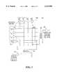
- FIG. 2is a more detailed schematic diagram of one way of implementing the system of FIG. 1 in which the display matrix can be used to either send or receive digitization signals;
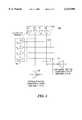
- FIG. 3is a schematic diagram of another implementation of the system of FIG. 1 in which the display matrix can also be used for either sending or receiving the digitization signals;
- FIG. 4is a schematic diagram of yet another manner of implementing the system of FIG. 1;
- FIG. 5Ais a schematic diagram of yet another means of implementing the system of FIG. 1 in which the display matrix is used to transmit the digitization signal;
- FIG. 5Bis aschematic diagram of a system similar to that of FIG. 5A, but which uses the display electrode matrix for digitization signal reception;
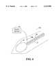
- FIG. 6is a schematic diagram of a signal-receiving or generating stylus tip for use in the system of this invention.
- This inventionincludes a means of using the electrodes of a display device as part of a position sensing circuit.
- the position sensing signalsare mixed with the display refresh signals on the display electrodes; i.e. the electrical positioning signals are superimposed on the display signals in such a way that they do not interfere with the display function.
- FIG. 1display-integrated stylus detection system 10 according to this invention.
- System 10is integrated with matrix display 12 comprising X and Y matrixes of crossed wires connected to X display driver 16 and Y display driver 14, for example a commonly-known LCD device.
- the system of this inventionis integrated into the LCD display device using X position signal driver 18 and Y position signal driver 20 in conjunction with stylus 22 and position sensing driver circuit 26.
- X position signal transmitter and receiver 18superimposes digitization signals on the portion of the matrix driven by X display driver 16 as is described below.
- Y position signal driver 20superimposes digitization signals on the display drive signals generated by Y display driver 14.
- Stylus 22then senses these digitization signals and reports the sensing to circuit 26 which, in conjunction with timing or frequency signals from drivers 18 and 20, determines the position of stylus 22 in relation to display matrix 12.
- the digitization signalsmay be transmitted from stylus 22 and received by position signal receivers in the place of 18 and 20.
- Another alternative operating modeis to include both transmission and reception functions in circuits 18 and 20 and stylus 22 so that the transmission and reception can be alternated as desired between the display device and the stylus.
- FIGS. 2, 3 and 4show four electrodes of a liquid crystal display (LCD) 12a, 12b and 12c, respectively, in the X (horizontal) direction, and 4 electrodes in the Y direction.
- LCDliquid crystal display
- System 10aoperates with Y position signal driver 20a and X position signal driver 18a which use amplifiers that are capacitively coupled to every other electrode of electrode matrix 12a; this connection scheme is schematically depicted by virtual capacitors 50, 51, and 60, 61, respectively.
- the LCD display drive amplifiers 30 through 33 and 40 through 43 already present in the display deviceact as the terminators or current sinks for the position signals.
- System 10amay also be used in an embodiment in which a position signal is transmitted from a stylus proximate the display surface and the display electrodes are used to receive the signal, in which case the X and Y position amplifiers in circuits 18a and 20a, respectively, are used for receiving rather than transmitting signals.
- FIGS. 3, 4, 5A and 5Bdisclose different means of conveying current through the electrodes of the display.
- transformers 82 and 92are used to pass current between a position amplifier and a display electrode.
- This approachis preferred where the display drivers have insufficient current drive to support the position sense current.
- This type of differential signal driver approachcan also be achieved with methods other than a transformer signal source.
- differential transconductance amplifiers 102 and 104, FIG. 4may be used in place of transformer windings 92 and 82, FIG. 3.
- the embodiment of FIG. 3may be used in a system in which the stylus sends the signal which is coupled to the matrix conductors and then sensed through the transformer windings.
- FIG. 4uses transconductance amplifiers such as amplifiers 102 and 104 in place of the transformer windings of FIG. 3. This embodiment can also be used for stylus-sensing embodiments.
- FIG. 5AYet another alternative for transmitting position signals from the matrix is shown in FIG. 5A, in which signal generators 110 and 116 in conjunction with power supplies 112 and 114, respectively, are used to generate the AC signal which is superimposed on the matrix drive signal at drive amplifiers 14d and 16d.
- FIG. 5Afor a stylus-transmitting embodiment of this type of circuit, FIG.
- signal measuring amplifiers 124 and 134are used in conjunction with resistors 122 and 132 to measure the received signal which is superimposed on the drive signal wave forms as a result of coupling from the stylus which transmits stylus position signals generated in conjunction with stylus position signal transmission circuit 26a to the matrix conductors.
- the circuit for only one display matrixis shown. In practice, there would be one such transmit and/or receive circuit for each matrix electrode employed in stylus position sensing.
- Each electrode of the displayis driven by a display driver which imposes a multi-level voltage signal with a certain waveshape as required to activate pixels at the electrode intersections.
- Display driversare generally voltage output devices which have low output impedance when they are driving the display.
- the X/Y Position circuits of this inventionmay be added to the display circuit as follows:
- AC Positioning signalsare connected to certain display electrodes by either capacitive or magnetic coupling or by direct connection.
- Positioning signalsare of high enough frequency and small enough magnitude that they do not interfere with the voltages which drive the display.
- the AC positioning signalsinduce currents which flow through the display electrodes, (across the visible portion of the display) and into the Display driver outputs (as in FIG. 2), or back into the position circuit (as in FIGS. 3 and 4).
- the magnetic fields produced by the AC positioning signalsare detected by a detecting circuit.
- Currentsare induced sequentially in the electrodes (or they use different frequencies or waveforms), so the signal received by the detecting circuit from each electrode is differentiable from the others. Also, it is possible to interpolate between the signals from adjacent current carrying electrodes, to achieve resolution finer than the distance between current carrying electrodes. It is also possible to transmit from the stylus and receive at the electrodes, or to alternately transmit from, then receive to the electrodes.
- a typical LCD displayhas electrodes on about 0.015" centers. It is not necessary to drive all display electrodes for position sensing. Typical electromagnetic digitizers require drive electrodes at 0.2" distance or more.
- Coupling of position signals into the display electrodesmay be done by making direct electrical contact with the electrodes, or capacitive coupling may be made by placing the positioning signals in close proximity with the appropriate display electrodes. In a similar manner, magnetic coupling of the positioning signals may be used to convey the signals to the display electrodes.
- the preferred embodiments described abovedo not require specific position signal connections to the display driver amplifiers. It may be preferable in some cases to use the display driver circuits to transmit both the display signals and the superimposed position signals to the display electrodes. This may be done by one of three methods. First, the display driver circuit can be modified to internally mix the display and position signals. Alternatively, an additional mixing circuit can be added to the output of the display driver. Finally, the display driver signal can be modulated by external means.
- FIG. 5Ashows a circuit configuration 10d where the power supply input to standard LCD display drivers is modulated with position signals. Superimposing position signals onto the driver power supply will cause the driver to mix the display and position data so its output is a combination of both signals.
- AC Positioning signalsare connected to certain display electrodes through the display driver outputs.
- the Positioning signalsare of high enough frequency and small enough magnitude that they do not interfere with the voltages which drive the display.
- the AC positioning signalsinduce modulated voltages on the display electrodes. These modulation signals may be detected either electrostatically or electromagnetically by a detector circuit on or above the display surface. This position information is then used to determine the position of said detector circuit.
- the electric fields produced by the AC positioning signalsare detected by a detector circuit. Voltages are induced sequentially in the electrodes (or they use different frequencies), so the signals received by the detector circuit from each electrode is differentiable from the others. Also, it is possible to interpolate between the signals from adjacent current carrying electrodes, to achieve fine resolution. It is also possible to transmit from the stylus and receive at the electrodes, or to alternately transmit from, then receive to the electrodes.
- a typical LCD displayhas electrodes on about 0.015" centers. It is not necessary to drive all of these electrodes for position sensing.
- Electromagnetic coupling of position signalswill require current flowing through the display electrodes.
- a terminator circuitis required at the end of each electrode opposite from the driver amplifier. Terminator circuits may be connected by making direct electrical contact with the display, or capacitive coupling may be made by placing the terminator circuits in close proximity with the appropriate display electrodes. In a similar manner, magnetic coupling may be used to connect the terminator circuits to the display electrodes.
- An alternative embodimentwould be to transmit position signals from the stylus.
- FIGS. 2, 3 and 5Aeach of the figures show four electrodes of a liquid crystal display (LCD) in the X (horizontal) direction, and 4 electrodes in the Y direction.
- a position signalis transmitted from a stylus which is proximate to the display surface.
- An embodiment of such a stylus 22ais shown in FIG. 6.
- Stylus 22aincludes wire loop 24 positioned in the stylus tip to transmit or pick up signals for an electromagnetic sensing system. Twisted wire pair 25 passes through shield 27 as is known in the art.
- Circuit 10b of FIG. 3differs from circuit 10a of FIG. 2 in its method of detecting position current from the electrodes of the display; circuit 10a picks up the position signal from a position amplifier which is capacitively coupled to certain of the display electrodes. Circuit 10b, FIG. 3, detects current induced into the display electrodes from the stylus by use of a transformer winding connected to the display electrode. This approach is preferred where the display drivers have insufficient current drive to support the position sense currents.
- This differential signal detector approachcan also be achieved with methods other than a transformer signal source. For example, a differential amplifier with high common mode impedance and low differential impedance may be used in place of the transformer windings.
- Each electrodeis driven by a display driver which imposes a multi-level voltage signal with certain waveshape as required to activate pixels at the electrode intersections.
- Display driversare generally voltage output devices which have low output impedance when they are driving the display.
- X/Y Position circuitsare added to the display circuits as follows:
- AC Position signal detector circuitsare connected to certain display electrodes by either capacitive or magnetic coupling or by direct connection.
- Positioning signalsare transmitted from a stylus proximate to the display surface. These signals are of high enough frequency and small enough magnitude that they do not interfere with the voltages which drive the display.
- the AC positioning signals coupled from the stylusinduce currents which flow through the display electrodes, (across the visible portion of the display) and into the Display driver outputs (as in FIGS. 2 and 5B), or back into the position circuit (as in FIG. 3).
- the currents produced by the AC positioning signalsare detected by a detecting circuit. Induced currents have different phase and magnitude in different electrodes such that the stylus position relative to them may be determined. Also, it is possible to interpolate between the signals from adjacent current carrying electrodes, to achieve resolution finer than the distance between current carrying electrodes.
- a typical LCD displayhas electrodes on about 0.015" centers. It is not necessary to receive from all display electrodes for position sensing. Typical electromagnetic digitizers require drive electrodes at 0.2" distance or more.
- Coupling of position signal detector circuits to the display electrodesmay be done by malting direct electrical contact with the electrodes, or capacitive coupling may be made by placing the positioning signal detector circuit in close proximity with the appropriate display electrodes. In a similar manner, magnetic coupling of the positioning signals may be used to convey the signals to the detector circuits.
Landscapes
- Engineering & Computer Science (AREA)
- General Engineering & Computer Science (AREA)
- Theoretical Computer Science (AREA)
- Human Computer Interaction (AREA)
- Physics & Mathematics (AREA)
- General Physics & Mathematics (AREA)
- Position Input By Displaying (AREA)
Abstract
Description
Claims (4)
Priority Applications (1)
| Application Number | Priority Date | Filing Date | Title |
|---|---|---|---|
| US08/434,558US6133906A (en) | 1993-03-15 | 1995-05-04 | Display-integrated stylus detection system |
Applications Claiming Priority (2)
| Application Number | Priority Date | Filing Date | Title |
|---|---|---|---|
| US3161493A | 1993-03-15 | 1993-03-15 | |
| US08/434,558US6133906A (en) | 1993-03-15 | 1995-05-04 | Display-integrated stylus detection system |
Related Parent Applications (1)
| Application Number | Title | Priority Date | Filing Date |
|---|---|---|---|
| US3161493AContinuation | 1993-03-15 | 1993-03-15 |
Publications (1)
| Publication Number | Publication Date |
|---|---|
| US6133906Atrue US6133906A (en) | 2000-10-17 |
Family
ID=21860448
Family Applications (1)
| Application Number | Title | Priority Date | Filing Date |
|---|---|---|---|
| US08/434,558Expired - Fee RelatedUS6133906A (en) | 1993-03-15 | 1995-05-04 | Display-integrated stylus detection system |
Country Status (1)
| Country | Link |
|---|---|
| US (1) | US6133906A (en) |
Cited By (102)
| Publication number | Priority date | Publication date | Assignee | Title |
|---|---|---|---|---|
| US6525712B1 (en)* | 1998-09-01 | 2003-02-25 | Jurgen Held | Method and device for manual recording of various events or states |
| US6592461B1 (en)* | 2000-02-04 | 2003-07-15 | Roni Raviv | Multifunctional computer interactive play system |
| US20030156087A1 (en)* | 2002-02-20 | 2003-08-21 | Boer Willem Den | Light sensitive display |
| US20030160808A1 (en)* | 2001-06-07 | 2003-08-28 | Synaptics, Inc. | Method and apparatus for controlling a display of data on a display screen |
| US20030218116A1 (en)* | 2002-02-20 | 2003-11-27 | Boer Willem Den | Image sensor with photosensitive thin film transistors |
| US20040095333A1 (en)* | 2002-08-29 | 2004-05-20 | N-Trig Ltd. | Transparent digitiser |
| US20040107369A1 (en)* | 2002-11-30 | 2004-06-03 | Barnes Cooper | Apparatus and method for multi-threaded processors performance control |
| US20040155871A1 (en)* | 2003-02-10 | 2004-08-12 | N-Trig Ltd. | Touch detection for a digitizer |
| US20040252108A1 (en)* | 2001-11-05 | 2004-12-16 | Yongnan Xuan | System and method for inputting graphs and words |
| US20050042880A1 (en)* | 2000-11-30 | 2005-02-24 | Kwok Siang Ping | Multilayered CMP stop for flat planarization |
| US20050110781A1 (en)* | 2003-11-25 | 2005-05-26 | Geaghan Bernard O. | Light emitting stylus and user input device using same |
| US20050110777A1 (en)* | 2003-11-25 | 2005-05-26 | Geaghan Bernard O. | Light-emitting stylus and user input device using same |
| US20050134751A1 (en)* | 2003-12-17 | 2005-06-23 | Adiel Abileah | Light sensitive display |
| US7053967B2 (en) | 2002-05-23 | 2006-05-30 | Planar Systems, Inc. | Light sensitive display |
| US20060209047A1 (en)* | 2005-03-18 | 2006-09-21 | Kwang-Jin Jeong | Touch screen plasma display |
| US20060209039A1 (en)* | 2003-07-21 | 2006-09-21 | Koninklijke Philips Electronics N.V. | Touch sensitive display for a portable device |
| US20070062852A1 (en)* | 2005-08-11 | 2007-03-22 | N-Trig Ltd. | Apparatus for Object Information Detection and Methods of Using Same |
| US20070216657A1 (en)* | 2006-03-17 | 2007-09-20 | Konicek Jeffrey C | Flat panel display screen operable for touch position determination system and methods |
| US20070252005A1 (en)* | 2006-05-01 | 2007-11-01 | Konicek Jeffrey C | Active matrix emissive display and optical scanner system, methods and applications |
| US20080065159A1 (en)* | 1996-01-08 | 2008-03-13 | Shlomo Ben-Haim | Electrical Muscle Controller |
| US20080150916A1 (en)* | 2006-12-20 | 2008-06-26 | 3M Innovative Properties Company | Untethered device employing tunable resonant circuit |
| US20080149401A1 (en)* | 2006-12-20 | 2008-06-26 | 3M Innovative Properties Company | Untethered stylus employing separate communication channels |
| US20080150917A1 (en)* | 2006-12-20 | 2008-06-26 | 3M Innovative Properties Company | Oscillator circuit for use in an untethered stylus |
| US20080149402A1 (en)* | 2006-12-20 | 2008-06-26 | 3M Innovative Properties Company | Untethered stylus employing low current power converter |
| US20080150658A1 (en)* | 2006-12-20 | 2008-06-26 | 3M Innovative Properties Company | Frequency control circuit for tuning a resonant circuit of an untethered device |
| US20080158165A1 (en)* | 2006-12-28 | 2008-07-03 | 3M Innovative Properties Company | Location sensing system and method employing adaptive drive signal adjustment |
| US20080156546A1 (en)* | 2006-12-28 | 2008-07-03 | 3M Innovative Properties Company | Untethered stylus empolying multiple reference frequency communication |
| US20090004738A1 (en)* | 1999-02-04 | 2009-01-01 | Pluristem Life Systems Inc. | Method and apparatus for maintenance and expansion of hemopoietic stem cells and/or progenitor cells |
| US20100170726A1 (en)* | 2009-01-06 | 2010-07-08 | Elan Microelectronics Corporation | Electronic stylus, capacitive touchpad module, and apparatus for touch input |
| US7773139B2 (en) | 2004-04-16 | 2010-08-10 | Apple Inc. | Image sensor with photosensitive thin film transistors |
| US7787259B2 (en) | 2006-12-28 | 2010-08-31 | 3M Innovative Properties Company | Magnetic shield for use in a location sensing system |
| US7840262B2 (en) | 2003-03-10 | 2010-11-23 | Impulse Dynamics Nv | Apparatus and method for delivering electrical signals to modify gene expression in cardiac tissue |
| US20100331739A1 (en)* | 2007-05-09 | 2010-12-30 | S.A.E Afikim | Method and system for predicting calving |
| US20110001729A1 (en)* | 2009-07-01 | 2011-01-06 | Hong Fu Jin Precision Industry ( Shenzhen) Co., Ltd. | Electronic device using electromagnetic input device |
| US7956851B2 (en) | 2006-12-20 | 2011-06-07 | 3M Innovative Properties Company | Self-tuning drive source employing input impedance phase detection |
| US20110157060A1 (en)* | 2009-12-29 | 2011-06-30 | Higgstec Inc. | Touch-control system, dual-input touch-control system and touch-detecting method |
| US8019421B2 (en) | 1999-03-05 | 2011-09-13 | Metacure Limited | Blood glucose level control |
| US20110298733A1 (en)* | 2010-06-04 | 2011-12-08 | Shih-Pin Chen | Touch display system and method for operating the same |
| US8134542B2 (en) | 2006-12-20 | 2012-03-13 | 3M Innovative Properties Company | Untethered stylus employing separate communication and power channels |
| US8207944B2 (en) | 2006-12-19 | 2012-06-26 | 3M Innovative Properties Company | Capacitance measuring circuit and method |
| US8207946B2 (en) | 2003-02-20 | 2012-06-26 | Apple Inc. | Light sensitive display |
| US8244371B2 (en) | 2005-03-18 | 2012-08-14 | Metacure Limited | Pancreas lead |
| US8321013B2 (en) | 1996-01-08 | 2012-11-27 | Impulse Dynamics, N.V. | Electrical muscle controller and pacing with hemodynamic enhancement |
| US8346363B2 (en) | 1999-03-05 | 2013-01-01 | Metacure Limited | Blood glucose level control |
| US8352031B2 (en) | 2004-03-10 | 2013-01-08 | Impulse Dynamics Nv | Protein activity modification |
| US20130091553A1 (en)* | 2011-10-06 | 2013-04-11 | Samsung Electronics Co., Ltd. | Method and apparatus for determining input |
| US20130088465A1 (en)* | 2010-06-11 | 2013-04-11 | N-Trig Ltd. | Object orientation detection with a digitizer |
| US20130169582A1 (en)* | 2012-01-01 | 2013-07-04 | Cypress Semiconductor Corporation | Contact identification and tracking on a capacitance sensing array |
| US20130207926A1 (en)* | 2012-02-15 | 2013-08-15 | Viktor Kremin | Stylus to host synchronization |
| US8548583B2 (en) | 2004-03-10 | 2013-10-01 | Impulse Dynamics Nv | Protein activity modification |
| US20130278537A1 (en)* | 2012-04-19 | 2013-10-24 | Motorola Mobility, Inc. | Touchscreen writing system |
| US8638320B2 (en) | 2011-06-22 | 2014-01-28 | Apple Inc. | Stylus orientation detection |
| US20140038524A1 (en)* | 2012-07-31 | 2014-02-06 | Research In Motion Limited | Method and apparatus pertaining to the timing of stylus location transmissions |
| US8655444B2 (en) | 1996-01-08 | 2014-02-18 | Impulse Dynamics, N.V. | Electrical muscle controller |
| US20140049478A1 (en)* | 2012-08-15 | 2014-02-20 | Samuel Brunet | Active stylus with passive mutual measurements |
| US20140055423A1 (en)* | 2011-12-07 | 2014-02-27 | Panasonic Corporation | Image-display-device drive method, image display device, and image display system |
| US8666495B2 (en) | 1999-03-05 | 2014-03-04 | Metacure Limited | Gastrointestinal methods and apparatus for use in treating disorders and controlling blood sugar |
| US20140062972A1 (en)* | 2011-12-07 | 2014-03-06 | Panasonic Corporation | Image-display-device drive method, image display device, and image display system |
| US20140062973A1 (en)* | 2011-12-07 | 2014-03-06 | Panasonic Corporation | Image-display-device drive method, image display device, and image display system |
| US20140062971A1 (en)* | 2011-12-07 | 2014-03-06 | Panasonic Corporation | Image-display-device drive method, image display device, and image display system |
| US20140085242A1 (en)* | 2011-12-07 | 2014-03-27 | Panasonic Corporation | Image-display-device drive method, image display device, and image display system |
| US8700161B2 (en) | 1999-03-05 | 2014-04-15 | Metacure Limited | Blood glucose level control |
| US20140111433A1 (en)* | 2012-10-19 | 2014-04-24 | Interphase Corporation | Motion compensation in an interactive display system |
| US20140152619A1 (en)* | 2006-06-09 | 2014-06-05 | Apple Inc. | Touch screen liquid crystal display |
| US8766954B2 (en) | 2010-12-21 | 2014-07-01 | Motorola Mobility Llc | Active stylus for use with touch-sensitive interfaces and corresponding method |
| US8792985B2 (en) | 2003-07-21 | 2014-07-29 | Metacure Limited | Gastrointestinal methods and apparatus for use in treating disorders and controlling blood sugar |
| US8825152B2 (en) | 1996-01-08 | 2014-09-02 | Impulse Dynamics, N.V. | Modulation of intracellular calcium concentration using non-excitatory electrical signals applied to the tissue |
| US8928635B2 (en) | 2011-06-22 | 2015-01-06 | Apple Inc. | Active stylus |
| US8934975B2 (en) | 2010-02-01 | 2015-01-13 | Metacure Limited | Gastrointestinal electrical therapy |
| US8963885B2 (en) | 2011-11-30 | 2015-02-24 | Google Technology Holdings LLC | Mobile device for interacting with an active stylus |
| US9063591B2 (en) | 2011-11-30 | 2015-06-23 | Google Technology Holdings LLC | Active styluses for interacting with a mobile device |
| US9101765B2 (en) | 1999-03-05 | 2015-08-11 | Metacure Limited | Non-immediate effects of therapy |
| CN104937524A (en)* | 2013-02-19 | 2015-09-23 | 戴尔产品有限公司 | Advanced in-cell touch optical pen |
| US9158393B2 (en) | 2012-12-18 | 2015-10-13 | Logitech Europe S.A. | Active stylus for touch sensing applications |
| US9176604B2 (en) | 2012-07-27 | 2015-11-03 | Apple Inc. | Stylus device |
| US9201556B2 (en) | 2006-11-08 | 2015-12-01 | 3M Innovative Properties Company | Touch location sensing system and method employing sensor data fitting to a predefined curve |
| US9268429B2 (en) | 2006-06-09 | 2016-02-23 | Apple Inc. | Integrated display and touch screen |
| US9289618B1 (en) | 1996-01-08 | 2016-03-22 | Impulse Dynamics Nv | Electrical muscle controller |
| US9310923B2 (en) | 2010-12-03 | 2016-04-12 | Apple Inc. | Input device for touch sensitive devices |
| US9329703B2 (en) | 2011-06-22 | 2016-05-03 | Apple Inc. | Intelligent stylus |
| US9367185B2 (en) | 2012-12-18 | 2016-06-14 | Logitech Europe S.A. | Method and system for discriminating stylus and touch interactions |
| US9454277B2 (en) | 2004-05-06 | 2016-09-27 | Apple Inc. | Multipoint touchscreen |
| US9557845B2 (en) | 2012-07-27 | 2017-01-31 | Apple Inc. | Input device for and method of communication with capacitive devices through frequency variation |
| US9652090B2 (en) | 2012-07-27 | 2017-05-16 | Apple Inc. | Device for digital communication through capacitive coupling |
| US9710095B2 (en) | 2007-01-05 | 2017-07-18 | Apple Inc. | Touch screen stack-ups |
| US9713723B2 (en) | 1996-01-11 | 2017-07-25 | Impulse Dynamics Nv | Signal delivery through the right ventricular septum |
| US9727193B2 (en) | 2010-12-22 | 2017-08-08 | Apple Inc. | Integrated touch screens |
| US9931503B2 (en) | 2003-03-10 | 2018-04-03 | Impulse Dynamics Nv | Protein activity modification |
| US9939935B2 (en) | 2013-07-31 | 2018-04-10 | Apple Inc. | Scan engine for touch controller architecture |
| US10048775B2 (en) | 2013-03-14 | 2018-08-14 | Apple Inc. | Stylus detection and demodulation |
| US10061450B2 (en) | 2014-12-04 | 2018-08-28 | Apple Inc. | Coarse scan and targeted active mode scan for touch |
| US10082890B2 (en) | 2015-09-01 | 2018-09-25 | Microsoft Technology Licensing, Llc | Electrostatic communication using an active stylus |
| US20190204939A1 (en)* | 2017-12-29 | 2019-07-04 | Lg Display Co., Ltd. | Touch display device, touch system, touch driving circuit, pen, and pen sensing method |
| US10474277B2 (en) | 2016-05-31 | 2019-11-12 | Apple Inc. | Position-based stylus communication |
| US10637933B2 (en) | 2016-05-26 | 2020-04-28 | Logitech Europe S.A. | Method and apparatus for transferring information between electronic devices |
| US11182012B2 (en)* | 2019-12-04 | 2021-11-23 | Samsung Display Co., Ltd. | Display device and portable device having the same |
| US11439815B2 (en) | 2003-03-10 | 2022-09-13 | Impulse Dynamics Nv | Protein activity modification |
| US11562639B2 (en) | 2020-08-24 | 2023-01-24 | Logitech Europe S.A. | Electronic system and method for improving human interaction and activities |
| US11779768B2 (en) | 2004-03-10 | 2023-10-10 | Impulse Dynamics Nv | Protein activity modification |
| US12148282B2 (en) | 2020-08-24 | 2024-11-19 | Logitech Europe S.A. | Electronic system and method for improving human interaction and activities |
| US12153764B1 (en) | 2020-09-25 | 2024-11-26 | Apple Inc. | Stylus with receive architecture for position determination |
| US12182737B2 (en) | 2021-08-10 | 2024-12-31 | Logitech Europe S.A. | Electronic system and method for claiming and reserving work areas |
Citations (23)
| Publication number | Priority date | Publication date | Assignee | Title |
|---|---|---|---|---|
| US3761877A (en)* | 1970-12-21 | 1973-09-25 | O Fernald | Optical graphic data tablet |
| US3772685A (en)* | 1972-03-29 | 1973-11-13 | Bunker Ramo | Touch responsive electric switch and device for the use thereof |
| US3832693A (en)* | 1971-08-29 | 1974-08-27 | Fujitsu Ltd | System for reading out the coordinates of information displayed on a matrix type display device |
| US3990070A (en)* | 1975-06-23 | 1976-11-02 | Rockwell International Corporation | Strobing scheme and keyboard sensing circuit for a one chip calculator |
| US4058849A (en)* | 1975-09-22 | 1977-11-15 | International Business Machines Corporation | System for converting a rough sketch to a finished drawing |
| US4125873A (en)* | 1977-06-29 | 1978-11-14 | International Business Machines Corporation | Display compressed image refresh system |
| US4190833A (en)* | 1977-02-18 | 1980-02-26 | Bejting Anders M T | Alphanumeric terminal having an optoelectric converter and an associated mono-pulse generating circuit |
| US4345248A (en)* | 1979-12-14 | 1982-08-17 | Citizen Watch Company Limited | Liquid crystal display device with write-in capability |
| US4363029A (en)* | 1980-11-17 | 1982-12-07 | Texas Instruments Incorporated | Switch for sensing proximity of an operator |
| US4405921A (en)* | 1980-05-12 | 1983-09-20 | Kabushiki Kaisha Suwa Seikosha | Liquid crystal display device |
| US4525032A (en)* | 1982-07-27 | 1985-06-25 | The Secretary Of State For Defence In Her Britannic Majesty's Government Of The United Kingdom Of Great Britain And Northern Ireland | Liquid crystal reusable signature comparison |
| GB2161935A (en)* | 1984-04-17 | 1986-01-22 | Ronald Peter Binstead | Touch operated keyboard |
| US4639720A (en)* | 1981-01-12 | 1987-01-27 | Harris Corporation | Electronic sketch pad |
| US4785564A (en)* | 1982-12-20 | 1988-11-22 | Motorola Inc. | Electronic notepad |
| US4839634A (en)* | 1986-12-01 | 1989-06-13 | More Edward S | Electro-optic slate for input/output of hand-entered textual and graphic information |
| US4841290A (en)* | 1986-09-25 | 1989-06-20 | Mitsubishi Denki Kabushiki Kaisha | Display unit |
| US4893115A (en)* | 1985-11-12 | 1990-01-09 | John Fluke Mfg. Co., Inc. | Touch sensitive visual display system |
| US4917308A (en)* | 1988-03-09 | 1990-04-17 | Manhardt Paul D | Flow rate limiting device for fuel dispensing nozzles |
| GB2223986A (en)* | 1987-01-15 | 1990-04-25 | Ronald Peter Binstead | Improvements in or relating to touch keypad systems |
| GB2250822A (en)* | 1989-05-17 | 1992-06-17 | Moonstone Designs Ltd | Proximity sensor |
| US5162782A (en)* | 1989-08-28 | 1992-11-10 | Mitsubishi Denki Kabushiki Kaisha | Display device with coordinate input function |
| US5194862A (en)* | 1990-06-29 | 1993-03-16 | U.S. Philips Corporation | Touch sensor array systems and display systems incorporating such |
| US5283556A (en)* | 1988-12-19 | 1994-02-01 | Sharp Kabushiki Kaisha | Tablet integrated with display |
- 1995
- 1995-05-04USUS08/434,558patent/US6133906A/ennot_activeExpired - Fee Related
Patent Citations (23)
| Publication number | Priority date | Publication date | Assignee | Title |
|---|---|---|---|---|
| US3761877A (en)* | 1970-12-21 | 1973-09-25 | O Fernald | Optical graphic data tablet |
| US3832693A (en)* | 1971-08-29 | 1974-08-27 | Fujitsu Ltd | System for reading out the coordinates of information displayed on a matrix type display device |
| US3772685A (en)* | 1972-03-29 | 1973-11-13 | Bunker Ramo | Touch responsive electric switch and device for the use thereof |
| US3990070A (en)* | 1975-06-23 | 1976-11-02 | Rockwell International Corporation | Strobing scheme and keyboard sensing circuit for a one chip calculator |
| US4058849A (en)* | 1975-09-22 | 1977-11-15 | International Business Machines Corporation | System for converting a rough sketch to a finished drawing |
| US4190833A (en)* | 1977-02-18 | 1980-02-26 | Bejting Anders M T | Alphanumeric terminal having an optoelectric converter and an associated mono-pulse generating circuit |
| US4125873A (en)* | 1977-06-29 | 1978-11-14 | International Business Machines Corporation | Display compressed image refresh system |
| US4345248A (en)* | 1979-12-14 | 1982-08-17 | Citizen Watch Company Limited | Liquid crystal display device with write-in capability |
| US4405921A (en)* | 1980-05-12 | 1983-09-20 | Kabushiki Kaisha Suwa Seikosha | Liquid crystal display device |
| US4363029A (en)* | 1980-11-17 | 1982-12-07 | Texas Instruments Incorporated | Switch for sensing proximity of an operator |
| US4639720A (en)* | 1981-01-12 | 1987-01-27 | Harris Corporation | Electronic sketch pad |
| US4525032A (en)* | 1982-07-27 | 1985-06-25 | The Secretary Of State For Defence In Her Britannic Majesty's Government Of The United Kingdom Of Great Britain And Northern Ireland | Liquid crystal reusable signature comparison |
| US4785564A (en)* | 1982-12-20 | 1988-11-22 | Motorola Inc. | Electronic notepad |
| GB2161935A (en)* | 1984-04-17 | 1986-01-22 | Ronald Peter Binstead | Touch operated keyboard |
| US4893115A (en)* | 1985-11-12 | 1990-01-09 | John Fluke Mfg. Co., Inc. | Touch sensitive visual display system |
| US4841290A (en)* | 1986-09-25 | 1989-06-20 | Mitsubishi Denki Kabushiki Kaisha | Display unit |
| US4839634A (en)* | 1986-12-01 | 1989-06-13 | More Edward S | Electro-optic slate for input/output of hand-entered textual and graphic information |
| GB2223986A (en)* | 1987-01-15 | 1990-04-25 | Ronald Peter Binstead | Improvements in or relating to touch keypad systems |
| US4917308A (en)* | 1988-03-09 | 1990-04-17 | Manhardt Paul D | Flow rate limiting device for fuel dispensing nozzles |
| US5283556A (en)* | 1988-12-19 | 1994-02-01 | Sharp Kabushiki Kaisha | Tablet integrated with display |
| GB2250822A (en)* | 1989-05-17 | 1992-06-17 | Moonstone Designs Ltd | Proximity sensor |
| US5162782A (en)* | 1989-08-28 | 1992-11-10 | Mitsubishi Denki Kabushiki Kaisha | Display device with coordinate input function |
| US5194862A (en)* | 1990-06-29 | 1993-03-16 | U.S. Philips Corporation | Touch sensor array systems and display systems incorporating such |
Cited By (213)
| Publication number | Priority date | Publication date | Assignee | Title |
|---|---|---|---|---|
| US8311629B2 (en) | 1996-01-08 | 2012-11-13 | Impulse Dynamics, N.V. | Electrical muscle controller |
| US8321013B2 (en) | 1996-01-08 | 2012-11-27 | Impulse Dynamics, N.V. | Electrical muscle controller and pacing with hemodynamic enhancement |
| US8825152B2 (en) | 1996-01-08 | 2014-09-02 | Impulse Dynamics, N.V. | Modulation of intracellular calcium concentration using non-excitatory electrical signals applied to the tissue |
| US20080065164A1 (en)* | 1996-01-08 | 2008-03-13 | Shlomo Ben-Haim | Electrical Muscle Controller |
| US8260416B2 (en) | 1996-01-08 | 2012-09-04 | Impulse Dynamics, N.V. | Electrical muscle controller |
| US8301247B2 (en) | 1996-01-08 | 2012-10-30 | Impulse Dynamics, N.V. | Electrical muscle controller |
| US20080065159A1 (en)* | 1996-01-08 | 2008-03-13 | Shlomo Ben-Haim | Electrical Muscle Controller |
| US8306616B2 (en) | 1996-01-08 | 2012-11-06 | Impulse Dynamics, N.V. | Electrical muscle controller |
| US9289618B1 (en) | 1996-01-08 | 2016-03-22 | Impulse Dynamics Nv | Electrical muscle controller |
| US8306617B2 (en) | 1996-01-08 | 2012-11-06 | Impulse Dynamics N.V. | Electrical muscle controller |
| US8655444B2 (en) | 1996-01-08 | 2014-02-18 | Impulse Dynamics, N.V. | Electrical muscle controller |
| US8958872B2 (en) | 1996-01-08 | 2015-02-17 | Impulse Dynamics, N.V. | Electrical muscle controller |
| US9186514B2 (en) | 1996-01-08 | 2015-11-17 | Impulse Dynamics Nv | Electrical muscle controller |
| US9713723B2 (en) | 1996-01-11 | 2017-07-25 | Impulse Dynamics Nv | Signal delivery through the right ventricular septum |
| US6525712B1 (en)* | 1998-09-01 | 2003-02-25 | Jurgen Held | Method and device for manual recording of various events or states |
| US20090004738A1 (en)* | 1999-02-04 | 2009-01-01 | Pluristem Life Systems Inc. | Method and apparatus for maintenance and expansion of hemopoietic stem cells and/or progenitor cells |
| US8666495B2 (en) | 1999-03-05 | 2014-03-04 | Metacure Limited | Gastrointestinal methods and apparatus for use in treating disorders and controlling blood sugar |
| US9101765B2 (en) | 1999-03-05 | 2015-08-11 | Metacure Limited | Non-immediate effects of therapy |
| US8700161B2 (en) | 1999-03-05 | 2014-04-15 | Metacure Limited | Blood glucose level control |
| US8346363B2 (en) | 1999-03-05 | 2013-01-01 | Metacure Limited | Blood glucose level control |
| US8019421B2 (en) | 1999-03-05 | 2011-09-13 | Metacure Limited | Blood glucose level control |
| US6592461B1 (en)* | 2000-02-04 | 2003-07-15 | Roni Raviv | Multifunctional computer interactive play system |
| US20050042880A1 (en)* | 2000-11-30 | 2005-02-24 | Kwok Siang Ping | Multilayered CMP stop for flat planarization |
| USRE47676E1 (en)* | 2001-06-07 | 2019-10-29 | Wacom Co., Ltd. | Method and apparatus for controlling a display of data on a display screen |
| US6904570B2 (en)* | 2001-06-07 | 2005-06-07 | Synaptics, Inc. | Method and apparatus for controlling a display of data on a display screen |
| US20030160808A1 (en)* | 2001-06-07 | 2003-08-28 | Synaptics, Inc. | Method and apparatus for controlling a display of data on a display screen |
| US7499026B2 (en)* | 2001-11-05 | 2009-03-03 | Yongnan Xuan | System and method for inputting graphs and words |
| US20040252108A1 (en)* | 2001-11-05 | 2004-12-16 | Yongnan Xuan | System and method for inputting graphs and words |
| US6947102B2 (en) | 2002-02-20 | 2005-09-20 | Plannar Systems, Inc. | Light sensitive display which senses decreases in light |
| US20030218116A1 (en)* | 2002-02-20 | 2003-11-27 | Boer Willem Den | Image sensor with photosensitive thin film transistors |
| US20040046900A1 (en)* | 2002-02-20 | 2004-03-11 | Boer Willem Den | Light sensitive display |
| US7280102B2 (en) | 2002-02-20 | 2007-10-09 | Planar Systems, Inc. | Light sensitive display |
| US20030156087A1 (en)* | 2002-02-20 | 2003-08-21 | Boer Willem Den | Light sensitive display |
| US9134851B2 (en) | 2002-02-20 | 2015-09-15 | Apple Inc. | Light sensitive display |
| US9411470B2 (en) | 2002-02-20 | 2016-08-09 | Apple Inc. | Light sensitive display with multiple data set object detection |
| US7872641B2 (en) | 2002-02-20 | 2011-01-18 | Apple Inc. | Light sensitive display |
| US9971456B2 (en) | 2002-02-20 | 2018-05-15 | Apple Inc. | Light sensitive display with switchable detection modes for detecting a fingerprint |
| US20030179323A1 (en)* | 2002-02-20 | 2003-09-25 | Adiel Abileah | Light sensitive display |
| US8441422B2 (en) | 2002-02-20 | 2013-05-14 | Apple Inc. | Light sensitive display with object detection calibration |
| US8570449B2 (en) | 2002-02-20 | 2013-10-29 | Apple Inc. | Light sensitive display with pressure sensor |
| US7408598B2 (en) | 2002-02-20 | 2008-08-05 | Planar Systems, Inc. | Light sensitive display with selected interval of light sensitive elements |
| US7023503B2 (en) | 2002-02-20 | 2006-04-04 | Planar Systems, Inc. | Image sensor with photosensitive thin film transistors |
| US6995743B2 (en) | 2002-02-20 | 2006-02-07 | Planar Systems, Inc. | Light sensitive display |
| US11073926B2 (en) | 2002-02-20 | 2021-07-27 | Apple Inc. | Light sensitive display |
| US8044930B2 (en) | 2002-05-23 | 2011-10-25 | Apple Inc. | Light sensitive display |
| US7053967B2 (en) | 2002-05-23 | 2006-05-30 | Planar Systems, Inc. | Light sensitive display |
| US9354735B2 (en) | 2002-05-23 | 2016-05-31 | Apple Inc. | Light sensitive display |
| US7830461B2 (en) | 2002-05-23 | 2010-11-09 | Apple Inc. | Light sensitive display |
| US7880733B2 (en) | 2002-05-23 | 2011-02-01 | Apple Inc. | Light sensitive display |
| US7880819B2 (en) | 2002-05-23 | 2011-02-01 | Apple Inc. | Light sensitive display |
| US7852417B2 (en) | 2002-05-23 | 2010-12-14 | Apple Inc. | Light sensitive display |
| US20080023232A1 (en)* | 2002-08-29 | 2008-01-31 | N-Trig Ltd. | Transparent digitiser |
| US8217918B2 (en) | 2002-08-29 | 2012-07-10 | N-Trig Ltd. | Transparent digitiser |
| US20040095333A1 (en)* | 2002-08-29 | 2004-05-20 | N-Trig Ltd. | Transparent digitiser |
| US7292229B2 (en) | 2002-08-29 | 2007-11-06 | N-Trig Ltd. | Transparent digitiser |
| US20040107369A1 (en)* | 2002-11-30 | 2004-06-03 | Barnes Cooper | Apparatus and method for multi-threaded processors performance control |
| US8593433B2 (en) | 2003-02-10 | 2013-11-26 | N-Trig Ltd. | Touch detection for a digitizer |
| US7843439B2 (en) | 2003-02-10 | 2010-11-30 | N-Trig Ltd. | Touch detection for a digitizer |
| US20040155871A1 (en)* | 2003-02-10 | 2004-08-12 | N-Trig Ltd. | Touch detection for a digitizer |
| US8373677B2 (en) | 2003-02-10 | 2013-02-12 | N-Trig Ltd. | Touch detection for a digitizer |
| US8400427B2 (en) | 2003-02-10 | 2013-03-19 | N-Trig Ltd. | Touch detection for a digitizer |
| US8228311B2 (en) | 2003-02-10 | 2012-07-24 | N-Trig Ltd. | Touch detection for a digitizer |
| US8952930B2 (en) | 2003-02-10 | 2015-02-10 | N-Trig Ltd. | Touch detection for a digitizer |
| US7372455B2 (en) | 2003-02-10 | 2008-05-13 | N-Trig Ltd. | Touch detection for a digitizer |
| US8207946B2 (en) | 2003-02-20 | 2012-06-26 | Apple Inc. | Light sensitive display |
| US11439815B2 (en) | 2003-03-10 | 2022-09-13 | Impulse Dynamics Nv | Protein activity modification |
| US8326416B2 (en) | 2003-03-10 | 2012-12-04 | Impulse Dynamics Nv | Apparatus and method for delivering electrical signals to modify gene expression in cardiac tissue |
| US7840262B2 (en) | 2003-03-10 | 2010-11-23 | Impulse Dynamics Nv | Apparatus and method for delivering electrical signals to modify gene expression in cardiac tissue |
| US9931503B2 (en) | 2003-03-10 | 2018-04-03 | Impulse Dynamics Nv | Protein activity modification |
| US8325143B2 (en)* | 2003-07-21 | 2012-12-04 | Creator Technology B.V. | Touch sensitive display for a portable device |
| US20060209039A1 (en)* | 2003-07-21 | 2006-09-21 | Koninklijke Philips Electronics N.V. | Touch sensitive display for a portable device |
| US8792985B2 (en) | 2003-07-21 | 2014-07-29 | Metacure Limited | Gastrointestinal methods and apparatus for use in treating disorders and controlling blood sugar |
| US7298367B2 (en)* | 2003-11-25 | 2007-11-20 | 3M Innovative Properties Company | Light emitting stylus and user input device using same |
| US20050110781A1 (en)* | 2003-11-25 | 2005-05-26 | Geaghan Bernard O. | Light emitting stylus and user input device using same |
| US20050110777A1 (en)* | 2003-11-25 | 2005-05-26 | Geaghan Bernard O. | Light-emitting stylus and user input device using same |
| US20090167728A1 (en)* | 2003-11-25 | 2009-07-02 | 3M Innovative Properties Company | Light-emitting stylus and user input device using same |
| US20050134751A1 (en)* | 2003-12-17 | 2005-06-23 | Adiel Abileah | Light sensitive display |
| US7009663B2 (en) | 2003-12-17 | 2006-03-07 | Planar Systems, Inc. | Integrated optical light sensitive active matrix liquid crystal display |
| US10352948B2 (en) | 2004-03-10 | 2019-07-16 | Impulse Dynamics Nv | Protein activity modification |
| US8977353B2 (en) | 2004-03-10 | 2015-03-10 | Impulse Dynamics Nv | Protein activity modification |
| US8352031B2 (en) | 2004-03-10 | 2013-01-08 | Impulse Dynamics Nv | Protein activity modification |
| US11779768B2 (en) | 2004-03-10 | 2023-10-10 | Impulse Dynamics Nv | Protein activity modification |
| US9440080B2 (en) | 2004-03-10 | 2016-09-13 | Impulse Dynamics Nv | Protein activity modification |
| US8548583B2 (en) | 2004-03-10 | 2013-10-01 | Impulse Dynamics Nv | Protein activity modification |
| US7773139B2 (en) | 2004-04-16 | 2010-08-10 | Apple Inc. | Image sensor with photosensitive thin film transistors |
| US8289429B2 (en) | 2004-04-16 | 2012-10-16 | Apple Inc. | Image sensor with photosensitive thin film transistors and dark current compensation |
| US10908729B2 (en) | 2004-05-06 | 2021-02-02 | Apple Inc. | Multipoint touchscreen |
| US11604547B2 (en) | 2004-05-06 | 2023-03-14 | Apple Inc. | Multipoint touchscreen |
| US10331259B2 (en) | 2004-05-06 | 2019-06-25 | Apple Inc. | Multipoint touchscreen |
| US9454277B2 (en) | 2004-05-06 | 2016-09-27 | Apple Inc. | Multipoint touchscreen |
| US12268882B2 (en) | 2004-12-09 | 2025-04-08 | Impulse Dynamics Nv | Beta blocker therapy with electrical administration |
| US20060209047A1 (en)* | 2005-03-18 | 2006-09-21 | Kwang-Jin Jeong | Touch screen plasma display |
| US8244371B2 (en) | 2005-03-18 | 2012-08-14 | Metacure Limited | Pancreas lead |
| US7902840B2 (en) | 2005-08-11 | 2011-03-08 | N-Trig Ltd. | Apparatus for object information detection and methods of using same |
| US9618316B2 (en) | 2005-08-11 | 2017-04-11 | Microsoft Technology Licensing, Llc | Apparatus for object information detection and methods of using same |
| US20090322352A1 (en)* | 2005-08-11 | 2009-12-31 | N-Trig Ltd. | Apparatus for object information detection and methods of using same |
| US9435628B2 (en) | 2005-08-11 | 2016-09-06 | Microsoft Technology Licensing, Llc | Apparatus for object information detection and methods of using same |
| US20070062852A1 (en)* | 2005-08-11 | 2007-03-22 | N-Trig Ltd. | Apparatus for Object Information Detection and Methods of Using Same |
| US8931780B2 (en) | 2005-08-11 | 2015-01-13 | N-Trig Ltd. | Apparatus for object information detection and methods of using same |
| US20070216657A1 (en)* | 2006-03-17 | 2007-09-20 | Konicek Jeffrey C | Flat panel display screen operable for touch position determination system and methods |
| US9207797B2 (en)* | 2006-03-17 | 2015-12-08 | Jeffrey C. Konicek | Flat panel display screen operable for touch position prediction methods |
| US8519978B2 (en) | 2006-03-17 | 2013-08-27 | Jeffrey Konicek | Flat panel display screen operable for touch position determination system and methods |
| US20140009439A1 (en)* | 2006-03-17 | 2014-01-09 | Jeffrey C. Konicek | Flat Panel Display Screen Operable For Touch Position Prediction Methods |
| US8144115B2 (en)* | 2006-03-17 | 2012-03-27 | Konicek Jeffrey C | Flat panel display screen operable for touch position determination system and methods |
| US20070252005A1 (en)* | 2006-05-01 | 2007-11-01 | Konicek Jeffrey C | Active matrix emissive display and optical scanner system, methods and applications |
| US8248396B2 (en) | 2006-05-01 | 2012-08-21 | Konicek Jeffrey C | Active matrix emissive display and optical scanner system |
| US20110057866A1 (en)* | 2006-05-01 | 2011-03-10 | Konicek Jeffrey C | Active Matrix Emissive Display and Optical Scanner System |
| US7859526B2 (en) | 2006-05-01 | 2010-12-28 | Konicek Jeffrey C | Active matrix emissive display and optical scanner system, methods and applications |
| US10191576B2 (en)* | 2006-06-09 | 2019-01-29 | Apple Inc. | Touch screen liquid crystal display |
| US20220057880A1 (en)* | 2006-06-09 | 2022-02-24 | Apple Inc. | Touch screen liquid crystal display |
| US11886651B2 (en)* | 2006-06-09 | 2024-01-30 | Apple Inc. | Touch screen liquid crystal display |
| US10976846B2 (en)* | 2006-06-09 | 2021-04-13 | Apple Inc. | Touch screen liquid crystal display |
| US11175762B2 (en) | 2006-06-09 | 2021-11-16 | Apple Inc. | Touch screen liquid crystal display |
| US20170147119A1 (en)* | 2006-06-09 | 2017-05-25 | Apple Inc. | Touch screen liquid crystal display |
| US9268429B2 (en) | 2006-06-09 | 2016-02-23 | Apple Inc. | Integrated display and touch screen |
| US9244561B2 (en)* | 2006-06-09 | 2016-01-26 | Apple Inc. | Touch screen liquid crystal display |
| US20140152619A1 (en)* | 2006-06-09 | 2014-06-05 | Apple Inc. | Touch screen liquid crystal display |
| US9575610B2 (en) | 2006-06-09 | 2017-02-21 | Apple Inc. | Touch screen liquid crystal display |
| US9201556B2 (en) | 2006-11-08 | 2015-12-01 | 3M Innovative Properties Company | Touch location sensing system and method employing sensor data fitting to a predefined curve |
| US8207944B2 (en) | 2006-12-19 | 2012-06-26 | 3M Innovative Properties Company | Capacitance measuring circuit and method |
| US8134542B2 (en) | 2006-12-20 | 2012-03-13 | 3M Innovative Properties Company | Untethered stylus employing separate communication and power channels |
| US8040329B2 (en) | 2006-12-20 | 2011-10-18 | 3M Innovative Properties Company | Frequency control circuit for tuning a resonant circuit of an untethered device |
| US7436164B2 (en) | 2006-12-20 | 2008-10-14 | 3M Innovative Properties Company | Untethered device employing tunable resonant circuit |
| US7956851B2 (en) | 2006-12-20 | 2011-06-07 | 3M Innovative Properties Company | Self-tuning drive source employing input impedance phase detection |
| US20080150916A1 (en)* | 2006-12-20 | 2008-06-26 | 3M Innovative Properties Company | Untethered device employing tunable resonant circuit |
| US20080149401A1 (en)* | 2006-12-20 | 2008-06-26 | 3M Innovative Properties Company | Untethered stylus employing separate communication channels |
| US20080150917A1 (en)* | 2006-12-20 | 2008-06-26 | 3M Innovative Properties Company | Oscillator circuit for use in an untethered stylus |
| US20080149402A1 (en)* | 2006-12-20 | 2008-06-26 | 3M Innovative Properties Company | Untethered stylus employing low current power converter |
| US8243049B2 (en) | 2006-12-20 | 2012-08-14 | 3M Innovative Properties Company | Untethered stylus employing low current power converter |
| US20080150658A1 (en)* | 2006-12-20 | 2008-06-26 | 3M Innovative Properties Company | Frequency control circuit for tuning a resonant circuit of an untethered device |
| US8159474B2 (en) | 2006-12-28 | 2012-04-17 | 3M Innovative Properties Company | Untethered stylus employing multiple reference frequency communication |
| US8089474B2 (en) | 2006-12-28 | 2012-01-03 | 3M Innovative Properties Company | Location sensing system and method employing adaptive drive signal adjustment |
| US8040330B2 (en) | 2006-12-28 | 2011-10-18 | 3M Innovative Properties Company | Untethered stylus empolying multiple reference frequency communication |
| US20080158165A1 (en)* | 2006-12-28 | 2008-07-03 | 3M Innovative Properties Company | Location sensing system and method employing adaptive drive signal adjustment |
| US20080156546A1 (en)* | 2006-12-28 | 2008-07-03 | 3M Innovative Properties Company | Untethered stylus empolying multiple reference frequency communication |
| US7787259B2 (en) | 2006-12-28 | 2010-08-31 | 3M Innovative Properties Company | Magnetic shield for use in a location sensing system |
| US7916501B2 (en) | 2006-12-28 | 2011-03-29 | 3M Innovative Properties Company | Magnetic shield for use in a location sensing system |
| US9710095B2 (en) | 2007-01-05 | 2017-07-18 | Apple Inc. | Touch screen stack-ups |
| US10521065B2 (en) | 2007-01-05 | 2019-12-31 | Apple Inc. | Touch screen stack-ups |
| US20100331739A1 (en)* | 2007-05-09 | 2010-12-30 | S.A.E Afikim | Method and system for predicting calving |
| US20100170726A1 (en)* | 2009-01-06 | 2010-07-08 | Elan Microelectronics Corporation | Electronic stylus, capacitive touchpad module, and apparatus for touch input |
| US8564553B2 (en)* | 2009-01-06 | 2013-10-22 | Elan Microelectronics Corporation | Electronic stylus, capacitive touchpad module, and apparatus for touch input |
| US20110001729A1 (en)* | 2009-07-01 | 2011-01-06 | Hong Fu Jin Precision Industry ( Shenzhen) Co., Ltd. | Electronic device using electromagnetic input device |
| US20110157060A1 (en)* | 2009-12-29 | 2011-06-30 | Higgstec Inc. | Touch-control system, dual-input touch-control system and touch-detecting method |
| US8934975B2 (en) | 2010-02-01 | 2015-01-13 | Metacure Limited | Gastrointestinal electrical therapy |
| US20110298733A1 (en)* | 2010-06-04 | 2011-12-08 | Shih-Pin Chen | Touch display system and method for operating the same |
| US20130088465A1 (en)* | 2010-06-11 | 2013-04-11 | N-Trig Ltd. | Object orientation detection with a digitizer |
| US9864441B2 (en) | 2010-06-11 | 2018-01-09 | Microsoft Technology Licensing, Llc | Object orientation detection with a digitizer |
| US9971422B2 (en) | 2010-06-11 | 2018-05-15 | Microsoft Technology Licensing, Llc | Object orientation detection with a digitizer |
| US9864440B2 (en)* | 2010-06-11 | 2018-01-09 | Microsoft Technology Licensing, Llc | Object orientation detection with a digitizer |
| US9310923B2 (en) | 2010-12-03 | 2016-04-12 | Apple Inc. | Input device for touch sensitive devices |
| US8766954B2 (en) | 2010-12-21 | 2014-07-01 | Motorola Mobility Llc | Active stylus for use with touch-sensitive interfaces and corresponding method |
| US10409434B2 (en) | 2010-12-22 | 2019-09-10 | Apple Inc. | Integrated touch screens |
| US9727193B2 (en) | 2010-12-22 | 2017-08-08 | Apple Inc. | Integrated touch screens |
| US9519361B2 (en) | 2011-06-22 | 2016-12-13 | Apple Inc. | Active stylus |
| US8928635B2 (en) | 2011-06-22 | 2015-01-06 | Apple Inc. | Active stylus |
| US8638320B2 (en) | 2011-06-22 | 2014-01-28 | Apple Inc. | Stylus orientation detection |
| US9329703B2 (en) | 2011-06-22 | 2016-05-03 | Apple Inc. | Intelligent stylus |
| US9921684B2 (en) | 2011-06-22 | 2018-03-20 | Apple Inc. | Intelligent stylus |
| US9495536B2 (en)* | 2011-10-06 | 2016-11-15 | Samsung Electronics Co., Ltd | Method and apparatus for determining input |
| US20130091553A1 (en)* | 2011-10-06 | 2013-04-11 | Samsung Electronics Co., Ltd. | Method and apparatus for determining input |
| US9063591B2 (en) | 2011-11-30 | 2015-06-23 | Google Technology Holdings LLC | Active styluses for interacting with a mobile device |
| US8963885B2 (en) | 2011-11-30 | 2015-02-24 | Google Technology Holdings LLC | Mobile device for interacting with an active stylus |
| US20140062973A1 (en)* | 2011-12-07 | 2014-03-06 | Panasonic Corporation | Image-display-device drive method, image display device, and image display system |
| US20140062971A1 (en)* | 2011-12-07 | 2014-03-06 | Panasonic Corporation | Image-display-device drive method, image display device, and image display system |
| US20140062972A1 (en)* | 2011-12-07 | 2014-03-06 | Panasonic Corporation | Image-display-device drive method, image display device, and image display system |
| US20140055423A1 (en)* | 2011-12-07 | 2014-02-27 | Panasonic Corporation | Image-display-device drive method, image display device, and image display system |
| US20140085242A1 (en)* | 2011-12-07 | 2014-03-27 | Panasonic Corporation | Image-display-device drive method, image display device, and image display system |
| US8982090B2 (en)* | 2012-01-01 | 2015-03-17 | Cypress Semiconductor Corporation | Optical stylus synchronization |
| US20130169582A1 (en)* | 2012-01-01 | 2013-07-04 | Cypress Semiconductor Corporation | Contact identification and tracking on a capacitance sensing array |
| US20130207926A1 (en)* | 2012-02-15 | 2013-08-15 | Viktor Kremin | Stylus to host synchronization |
| US10678355B2 (en) | 2012-02-15 | 2020-06-09 | Wacom Co., Ltd. | Stylus to host synchronization |
| US12379794B2 (en) | 2012-02-15 | 2025-08-05 | Wacom Co., Ltd. | Stylus to host synchronization using a magnetic field |
| US11093055B2 (en) | 2012-02-15 | 2021-08-17 | Wacom Co., Ltd. | Stylus to host synchronization using a magnetic field |
| US10228780B2 (en) | 2012-02-15 | 2019-03-12 | Wacom Co., Ltd. | Stylus to host synchronization using a magnetic field |
| US20130278537A1 (en)* | 2012-04-19 | 2013-10-24 | Motorola Mobility, Inc. | Touchscreen writing system |
| US9582105B2 (en) | 2012-07-27 | 2017-02-28 | Apple Inc. | Input device for touch sensitive devices |
| US9557845B2 (en) | 2012-07-27 | 2017-01-31 | Apple Inc. | Input device for and method of communication with capacitive devices through frequency variation |
| US9652090B2 (en) | 2012-07-27 | 2017-05-16 | Apple Inc. | Device for digital communication through capacitive coupling |
| US9176604B2 (en) | 2012-07-27 | 2015-11-03 | Apple Inc. | Stylus device |
| US20140038524A1 (en)* | 2012-07-31 | 2014-02-06 | Research In Motion Limited | Method and apparatus pertaining to the timing of stylus location transmissions |
| USRE48310E1 (en)* | 2012-08-15 | 2020-11-17 | Wacom Co., Ltd. | Active stylus with passive mutual measurements |
| US9563304B2 (en)* | 2012-08-15 | 2017-02-07 | Atmel Corporation | Active stylus with passive mutual measurements |
| US20140049478A1 (en)* | 2012-08-15 | 2014-02-20 | Samuel Brunet | Active stylus with passive mutual measurements |
| US20140111433A1 (en)* | 2012-10-19 | 2014-04-24 | Interphase Corporation | Motion compensation in an interactive display system |
| US8982050B2 (en)* | 2012-10-19 | 2015-03-17 | Interphase Corporation | Motion compensation in an interactive display system |
| US9158393B2 (en) | 2012-12-18 | 2015-10-13 | Logitech Europe S.A. | Active stylus for touch sensing applications |
| US9367186B2 (en) | 2012-12-18 | 2016-06-14 | Logitech Europe S.A. | Method and system for discriminating stylus and touch interactions |
| US9367185B2 (en) | 2012-12-18 | 2016-06-14 | Logitech Europe S.A. | Method and system for discriminating stylus and touch interactions |
| CN104937524A (en)* | 2013-02-19 | 2015-09-23 | 戴尔产品有限公司 | Advanced in-cell touch optical pen |
| CN104937524B (en)* | 2013-02-19 | 2018-10-09 | 戴尔产品有限公司 | Advanced embedded touch optical pen |
| US10048775B2 (en) | 2013-03-14 | 2018-08-14 | Apple Inc. | Stylus detection and demodulation |
| US11687192B2 (en) | 2013-07-31 | 2023-06-27 | Apple Inc. | Touch controller architecture |
| US9939935B2 (en) | 2013-07-31 | 2018-04-10 | Apple Inc. | Scan engine for touch controller architecture |
| US10845901B2 (en) | 2013-07-31 | 2020-11-24 | Apple Inc. | Touch controller architecture |
| US12340048B2 (en) | 2013-07-31 | 2025-06-24 | Apple Inc. | Touch controller architecture |
| US10067580B2 (en) | 2013-07-31 | 2018-09-04 | Apple Inc. | Active stylus for use with touch controller architecture |
| US10061449B2 (en) | 2014-12-04 | 2018-08-28 | Apple Inc. | Coarse scan and targeted active mode scan for touch and stylus |
| US10664113B2 (en) | 2014-12-04 | 2020-05-26 | Apple Inc. | Coarse scan and targeted active mode scan for touch and stylus |
| US10061450B2 (en) | 2014-12-04 | 2018-08-28 | Apple Inc. | Coarse scan and targeted active mode scan for touch |
| US10067618B2 (en) | 2014-12-04 | 2018-09-04 | Apple Inc. | Coarse scan and targeted active mode scan for touch |
| US10082890B2 (en) | 2015-09-01 | 2018-09-25 | Microsoft Technology Licensing, Llc | Electrostatic communication using an active stylus |
| US10637933B2 (en) | 2016-05-26 | 2020-04-28 | Logitech Europe S.A. | Method and apparatus for transferring information between electronic devices |
| US11539799B2 (en) | 2016-05-26 | 2022-12-27 | Logitech Europe S.A. | Method and apparatus for transferring information between electronic devices |
| US10474277B2 (en) | 2016-05-31 | 2019-11-12 | Apple Inc. | Position-based stylus communication |
| US20190204939A1 (en)* | 2017-12-29 | 2019-07-04 | Lg Display Co., Ltd. | Touch display device, touch system, touch driving circuit, pen, and pen sensing method |
| US10768719B2 (en)* | 2017-12-29 | 2020-09-08 | Lg Display Co., Ltd. | Touch display device, touch system, touch driving circuit, pen, and pen sensing method |
| US11182012B2 (en)* | 2019-12-04 | 2021-11-23 | Samsung Display Co., Ltd. | Display device and portable device having the same |
| US11562639B2 (en) | 2020-08-24 | 2023-01-24 | Logitech Europe S.A. | Electronic system and method for improving human interaction and activities |
| US12148282B2 (en) | 2020-08-24 | 2024-11-19 | Logitech Europe S.A. | Electronic system and method for improving human interaction and activities |
| US11562638B2 (en) | 2020-08-24 | 2023-01-24 | Logitech Europe S.A. | Electronic system and method for improving human interaction and activities |
| US12153764B1 (en) | 2020-09-25 | 2024-11-26 | Apple Inc. | Stylus with receive architecture for position determination |
| US12182737B2 (en) | 2021-08-10 | 2024-12-31 | Logitech Europe S.A. | Electronic system and method for claiming and reserving work areas |
Similar Documents
| Publication | Publication Date | Title |
|---|---|---|
| US6133906A (en) | Display-integrated stylus detection system | |
| EP0610262B1 (en) | See-through digitizer with clear conductive grid | |
| EP3226109B1 (en) | Active stylus pen and touch sensing system including the same | |
| US4853498A (en) | Position measurement apparatus for capacitive touch panel system | |
| US7084933B2 (en) | Touch panel for display device | |
| US5554828A (en) | Integration of pen-based capability into a field emission device system | |
| US5657054A (en) | Determination of pen location on display apparatus using piezoelectric point elements | |
| US5926168A (en) | Remote pointers for interactive televisions | |
| US8593433B2 (en) | Touch detection for a digitizer | |
| EP0622723B1 (en) | System and method for dynamically labeled touch sensitive buttons in a digitizing display | |
| US7436393B2 (en) | Touch panel for display device | |
| US20160231854A1 (en) | Orthogonal frequency division scanning method for sensors | |
| US5854448A (en) | Coordinate input device used for inputting characters and drawings into a personal computer/word processor | |
| JPH11305932A (en) | Coordinate input device and display integrated type coordinate input device | |
| EP0712090B1 (en) | Touch sensor input system for a computer display | |
| EP0602913B1 (en) | Method of use of multiple input styli in a system of multiple computers | |
| JPH0895701A (en) | Transparent digitizer for touch panel | |
| JP3225716B2 (en) | Information input device | |
| US5657053A (en) | Method for determining pen location on display apparatus using piezoelectric point elements | |
| JPH06119101A (en) | Display integrated type tablet device | |
| JPH02144716A (en) | Capacitive coupling transparent coordinate input device | |
| EP0798659A1 (en) | Image generation and display method and apparatus | |
| JPH0580011B2 (en) | ||
| KR100300328B1 (en) | A digitiger system reducing leakage current and a method therefor | |
| JPH10105323A (en) | Amplitude modulation digitizer detection method |
Legal Events
| Date | Code | Title | Description |
|---|---|---|---|
| FEPP | Fee payment procedure | Free format text:PAYOR NUMBER ASSIGNED (ORIGINAL EVENT CODE: ASPN); ENTITY STATUS OF PATENT OWNER: LARGE ENTITY | |
| FPAY | Fee payment | Year of fee payment:4 | |
| AS | Assignment | Owner name:3M MICROTOUCH SYSTEMS INC., MASSACHUSETTS Free format text:CHANGE OF NAME;ASSIGNOR:MICROTOUCH SYSTEMS, INC.;REEL/FRAME:019597/0398 Effective date:20010425 | |
| AS | Assignment | Owner name:3M TOUCH SYSTEMS INC., MASSACHUSETTS Free format text:CHANGE OF NAME;ASSIGNOR:3M MICROTOUCH SYSTEMS, INC.;REEL/FRAME:019725/0667 Effective date:20010425 | |
| AS | Assignment | Owner name:3M INNOVATIVE PROPERTIES COMPANY, MINNESOTA Free format text:ASSIGNMENT OF ASSIGNORS INTEREST;ASSIGNOR:3M TOUCH SYSTEMS INC., A CORPORATION OF MASSACHUSETTS;REEL/FRAME:019744/0534 Effective date:20070823 | |
| FPAY | Fee payment | Year of fee payment:8 | |
| REMI | Maintenance fee reminder mailed | ||
| LAPS | Lapse for failure to pay maintenance fees | ||
| STCH | Information on status: patent discontinuation | Free format text:PATENT EXPIRED DUE TO NONPAYMENT OF MAINTENANCE FEES UNDER 37 CFR 1.362 | |
| FP | Lapsed due to failure to pay maintenance fee | Effective date:20121017 |