US6133885A - Non-telescoping antenna assembly for a wireless communication device - Google Patents
Non-telescoping antenna assembly for a wireless communication deviceDownload PDFInfo
- Publication number
- US6133885A US6133885AUS09/185,364US18536498AUS6133885AUS 6133885 AUS6133885 AUS 6133885AUS 18536498 AUS18536498 AUS 18536498AUS 6133885 AUS6133885 AUS 6133885A
- Authority
- US
- United States
- Prior art keywords
- post
- bushing
- antenna
- telescoping
- telescoping antenna
- Prior art date
- Legal status (The legal status is an assumption and is not a legal conclusion. Google has not performed a legal analysis and makes no representation as to the accuracy of the status listed.)
- Expired - Lifetime
Links
- 230000007246mechanismEffects0.000claimsabstractdescription9
- 238000009987spinningMethods0.000claimsdescription3
- 230000001413cellular effectEffects0.000description3
- PXHVJJICTQNCMI-UHFFFAOYSA-NNickelChemical compound[Ni]PXHVJJICTQNCMI-UHFFFAOYSA-N0.000description2
- 239000000463materialSubstances0.000description2
- 239000002184metalSubstances0.000description2
- 229910052751metalInorganic materials0.000description2
- 238000012986modificationMethods0.000description2
- 230000004048modificationEffects0.000description2
- 229910001369BrassInorganic materials0.000description1
- 239000004677NylonSubstances0.000description1
- 239000010951brassSubstances0.000description1
- 230000013011matingEffects0.000description1
- 239000007769metal materialSubstances0.000description1
- 229910052759nickelInorganic materials0.000description1
- 239000012811non-conductive materialSubstances0.000description1
- 229920001778nylonPolymers0.000description1
- 229920002725thermoplastic elastomerPolymers0.000description1
Images


Classifications
- H—ELECTRICITY
- H01—ELECTRIC ELEMENTS
- H01Q—ANTENNAS, i.e. RADIO AERIALS
- H01Q1/00—Details of, or arrangements associated with, antennas
- H01Q1/12—Supports; Mounting means
- H—ELECTRICITY
- H01—ELECTRIC ELEMENTS
- H01Q—ANTENNAS, i.e. RADIO AERIALS
- H01Q1/00—Details of, or arrangements associated with, antennas
- H01Q1/12—Supports; Mounting means
- H01Q1/22—Supports; Mounting means by structural association with other equipment or articles
- H01Q1/24—Supports; Mounting means by structural association with other equipment or articles with receiving set
- H01Q1/241—Supports; Mounting means by structural association with other equipment or articles with receiving set used in mobile communications, e.g. GSM
- H01Q1/242—Supports; Mounting means by structural association with other equipment or articles with receiving set used in mobile communications, e.g. GSM specially adapted for hand-held use
- H—ELECTRICITY
- H01—ELECTRIC ELEMENTS
- H01R—ELECTRICALLY-CONDUCTIVE CONNECTIONS; STRUCTURAL ASSOCIATIONS OF A PLURALITY OF MUTUALLY-INSULATED ELECTRICAL CONNECTING ELEMENTS; COUPLING DEVICES; CURRENT COLLECTORS
- H01R13/00—Details of coupling devices of the kinds covered by groups H01R12/70 or H01R24/00 - H01R33/00
- H01R13/02—Contact members
- H01R13/20—Pins, blades, or sockets shaped, or provided with separate member, to retain co-operating parts together
- H01R13/207—Pins, blades, or sockets shaped, or provided with separate member, to retain co-operating parts together by screw-in connection
- H—ELECTRICITY
- H01—ELECTRIC ELEMENTS
- H01R—ELECTRICALLY-CONDUCTIVE CONNECTIONS; STRUCTURAL ASSOCIATIONS OF A PLURALITY OF MUTUALLY-INSULATED ELECTRICAL CONNECTING ELEMENTS; COUPLING DEVICES; CURRENT COLLECTORS
- H01R2201/00—Connectors or connections adapted for particular applications
- H01R2201/02—Connectors or connections adapted for particular applications for antennas
- H—ELECTRICITY
- H01—ELECTRIC ELEMENTS
- H01R—ELECTRICALLY-CONDUCTIVE CONNECTIONS; STRUCTURAL ASSOCIATIONS OF A PLURALITY OF MUTUALLY-INSULATED ELECTRICAL CONNECTING ELEMENTS; COUPLING DEVICES; CURRENT COLLECTORS
- H01R2201/00—Connectors or connections adapted for particular applications
- H01R2201/16—Connectors or connections adapted for particular applications for telephony
Definitions
- the present inventionrelates to non-telescoping antennas for wireless communication devices.
- Most wireless communication devicessuch as cellular radiotelephones, employ an antenna for radiating and receiving radio frequency (RF) signals.
- the antennais typically carried on the external surface of the device. Because of its external location on the device, the antenna is subject to manipulation by a user of the device. While some of the antennas are telescoping antennas adapted for longitudinal movement by a user between stowed and extended positions, other antennas are non-telescoping antennas not meant for movement by the user.
- One such non-telescoping antenna, the stubby antennausually employs a threaded end that screws into a threaded receiving socket on the device, thereby, attaching the stubby antenna to the device.
- Detachment of the stubby antennais accomplished by rotating the stubby antenna in a direction opposite to the direction it was rotated for attachment. Users of the device, inadvertently or otherwise, have a tendency to manipulate and detach such non-telescoping antennas. Unfortunately, repeated detachments can increase the risk of foreign material entering the device as well as strip the screw threads on the base of the antenna and/or in the receiving socket of the device.
- an antenna assembly for a non-telescoping antennathat allows a user to manipulate the non-telescoping antenna without detaching it from the device.
- FIG. 1is a front, bottom and right side perspective view of a wireless communication device employing an antenna assembly
- FIG. 2is an enlarged, exploded perspective view of the antenna assembly of FIG. 1;
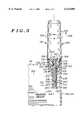
- FIG. 3is an enlarged, partial cross-sectional view of the wireless communication device of FIG. 1 taken across section lines 3--3 in FIG. 1.
- An antenna assembly for a wireless communication devicehas a non-telescoping antenna, a bushing and a post.
- the bushinghas an attachment mechanism to secure the bushing to the wireless communication device.
- the posthas two ends. One end of the post is joined to the non-telescoping antenna. The other end of the post adapted to electrically connect the non-telescoping antenna to a transceiver of the wireless communication device.
- the postis journaled in the bushing to permit radial movement of the non-telescoping antenna without unsecuring the bushing from the wireless communication device.
- a wireless communication device 100which is shown in FIG. 1 to be a foldable cellular radiotelephone, has top and bottom housings 102 and 104 rotatably joined by a hinge 105.
- the top housing 102is formed from front and rear housing portions 106 and 107 mated at junction line 108.
- a speaker 110 and a display 111are carried on the front housing portion 106.
- the bottom housing 104is formed from front and rear housing portions 114 and 115 mated at junction line 116 to enclose a circuit board 302 with transceiver circuitry 304 as shown in FIG. 3.
- a keypad 117 of FIG. 1 and a microphone 119are carried on the front housing portion 114.
- An antenna assembly 118is mounted to a boss 120 positioned at a top end 122 of the bottom housing 104.
- the antenna assembly 118has a non-telescoping antenna 200, a post 202 and a bushing 204, as shown in FIG. 2.
- the non-telescoping antenna 200is shown in FIG. 2 as a stubby antenna.
- the non-telescoping antenna 200has a radiating and receiving element, such as a metallic helical coil and/or a metallic wire or rod, encased within an overmolded cap 206 formed of a thermoplastic elastomer or other suitable nonconductive material.
- the cap 206is substantially cylindrical with a slight taper such that a diameter of end 208 is less than a diameter of end 209.
- a cylindrical neck 210 of the non-telescoping antenna 200is integrally joined to the cap 206 at the end 209.
- the neck 210has a diameter less than the diameter of the end 209 of the cap 206.
- the neck 210has three spaced crush ribs 212 circumscribed thereabout.
- the ribs 212are integral to the neck 210 and raised such that a diameter of the neck 210 at the ribs 212 is greater than a diameter of the neck 210 next to the ribs 212.
- the post 202is substantially cylindrical and formed of nickel plated brass or other metallic material.
- the post 202has two ends. One end of the post 202 is joined to the non-telescoping antenna 200.
- the post 202extends through the neck 210 and into the cap 206 to electrically connect to the radiating and receiving element.
- the non-telescoping antenna 200resides concentrically around a longitudinal axis 214 of the post 202.
- the other end of the post 202is adapted to electrically connect the non-telescoping antenna 200 to the transceiver circuitry 304 of FIG. 3.
- FIG. 2shows that the end of the post 202 distal to the non-telescoping antenna 200 is defined by a chamfered surface 216.
- the post 202has a channel 218 located between its ends.
- the channel 218circumscribes the post 202 and is bounded by a ramp 220 and a wall 221.
- the channel 218separates the post 202 into two cylindrical segments 222 and 223, each with a constant diameter Segment 222 resides between the channel 218 and the neck 210, and segment 223 resides between the channel 218 and the chamfered surface 216.
- the bushing 204which is formed of engineering grade nylon or other suitable material, is defined by integrally joined cup and stem portions 226 and 227.
- the cup portion 226is a hollow cylinder defined by an inner surface 306 of FIG. 3 and an outer surface 228 of FIG. 2 extending between ends 230 and 231
- the end 230is defined by a wide opening 307 of FIG. 3 around which a circular rim 232 of FIG. 2 is circumscribed.
- the rim 232is flush with the inner surface 306 but extends beyond the outer surface 228.
- the rim 232 of FIG. 2includes a plurality of notches 308 shown in FIG.
- the end 231is defined by a narrow opening 310 of FIG. 3, which is smaller in diameter than the wide opening 307.
- the stem portion 227 of FIG. 2, which extends from the end 231 of the cup portion 226,is a hollow cylinder defined by an inner surface 312 of FIG. 3 and an outer surface 228 of FIG. 2.
- the inner surface 312is flush with an inner surface of the end 231 of the cup portion 226 that surrounds the narrow opening 310.
- the stem portion 227has two attachment mechanisms 238 and 240.
- the attachment mechanism 238is used to secure the bushing 204 to the device 100 of FIG. 1.
- the attachment mechanism 238 of FIG. 2comprises an integral screw thread 242 spiraled around the outer surface 236 of the stem portion 227 proximate to the cup portion 226.
- the attachment mechanism 240is used to join the bushing 204 to the post 202.
- the attachment mechanism 240comprises opposing spring fingers 244 integrally formed in the inner and outer surfaces 312 and 236 of the stem portion 227 from longitudinal slots 246 extending from an end of the stem portion 227 that is distal to the cup portion 226.
- the spring fingers 244have angled feet 248 at the inner surface 312.
- Attachment of the antenna assembly 118 to the device 100 of FIG. 1is accomplished in the following manner, which will be described in conjunction with FIGS. 1-3.
- the bushing 204is secured to the device 100.
- the boss 120provides a cylindrical passage 314 through the front and rear housing portions 114 and 115 of the bottom housing 104.
- the passage 314is lined with a reciprocal screw thread 316.
- the bushing 204is lowered into the boss 120 and the passage 314 until the screw thread 242 meets the reciprocal screw thread 314.
- the bushing 204is rotated clockwise mating the screw thread 242 and the reciprocal screw thread 314, and drawing the bushing 204 further into the device 100.
- the bushing 204is preferably assembled to the device 100 using an automated screw machine that has a driving tool configured hold the bushing 204 by the plurality of notches 308 of the rim 232.
- Manual assembly of the bushing 204 to the device 100may quickly be accomplished via a customized hand tool that engages the plurality of notches 308 or engages the opposing flat edge sections 234 on the side edge of the rim 232.
- the non-telescoping antenna 200is assembled to the device 100.
- the non-telescoping antenna 200is aligned and lowered so that the post 202 passes through the wide and narrow openings 307 and 310 of the cup portion 226 of the bushing 204 and into the stem portion 227 of the bushing 204.
- the non-telescoping antenna 200is further lowered pushing the segment 223 of the post 202 past the spring fingers 244, which are outwardly deflected from a rest position as the chamfered surface 216 meets and moves past angled feet 248, and passing the neck 210 through the wide opening 307 and into the cup portion 226.
- the radiating and receiving element in the cap 206 of the non-telescoping antenna 200is electrically connected to the transceiver circuitry 304 via the post 202, the spring contact 318, the pad 320 and the connection 322.
- the non-telescoping antenna 200enjoys z-axis, snap-in assembly that is easily accomplished manually or by an automated robot arm.
- the antenna assembly 118is shown assembled to the device 100 in FIG. 3.
- the post 202is journaled in the bushing 204 between the ends of the post 202 to permit clockwise and counterclockwise radial movement of the non-telescoping antenna 200 in the direction of arrows 324 and 325, respectively, without disassembling the bushing 204 or the non-telescoping antenna 200 from the device 100.
- the crush ribs 212 of the neck 210engage the inner surface 306 of the cup portion 226 to provide enough resistance to prevent the non-telescoping antenna 200 from spinning freely but not enough resistance to back the bushing 204 out of the boss 120.
- the feet 248 of the spring fingers 244remain captured in the channel 218 of the post 202 and the segment 223 of the post 202 remains in contact with the spring contact 318 to ensure that the radiating and receiving element of the non-telescoping antenna 200 remains electrically connected to the transceiver circuitry 304.
- the bushing 204engages the post 202 to prevent any significant movement of the non-telescoping antenna 200 along the longitudinal axis 214 of the post 202, such as in the event that the non-telescoping antenna 200 is pulled away from the device 100 in the direction of arrow 326.
- the antenna assembly 118is preferably disassembled from the device 100 by engaging the opposing flat edge sections 234 on the side edge of the rim 232 using the aforementioned customized hand tool and rotating the bushing 204 with the tool in a counterclockwise direction causing the bushing 204 to back out of the boss 120.
- the attachment mechanism 238 of the bushing 204could alternately employ arms that snap into channels formed in the boss 120, thereby, providing a complete snap-in solution.
- the antenna assemblywill also find application in cordless radiotelephones, satellite radiotelephones, two-way radios, plug-in transceiver modules, personal digital assistants, and the like. It is therefore intended in the appended claims to cover all such changes and modifications which fall within the true spirit and scope of the invention.
Landscapes
- Engineering & Computer Science (AREA)
- Computer Networks & Wireless Communication (AREA)
- Support Of Aerials (AREA)
- Details Of Aerials (AREA)
Abstract
Description
Claims (9)
Priority Applications (4)
| Application Number | Priority Date | Filing Date | Title |
|---|---|---|---|
| US09/185,364US6133885A (en) | 1998-11-03 | 1998-11-03 | Non-telescoping antenna assembly for a wireless communication device |
| KR1019990048070AKR100320056B1 (en) | 1998-11-03 | 1999-11-02 | Non-telescoping antenna assembly for a wireless communication device |
| CN99123406ACN100592571C (en) | 1998-11-03 | 1999-11-03 | Non-retractable antenna assembly for wireless communication devices |
| GB9926073AGB2346263B (en) | 1998-11-03 | 1999-11-03 | Non-telescoping antenna assembly for a wireless communication device |
Applications Claiming Priority (1)
| Application Number | Priority Date | Filing Date | Title |
|---|---|---|---|
| US09/185,364US6133885A (en) | 1998-11-03 | 1998-11-03 | Non-telescoping antenna assembly for a wireless communication device |
Publications (1)
| Publication Number | Publication Date |
|---|---|
| US6133885Atrue US6133885A (en) | 2000-10-17 |
Family
ID=22680684
Family Applications (1)
| Application Number | Title | Priority Date | Filing Date |
|---|---|---|---|
| US09/185,364Expired - LifetimeUS6133885A (en) | 1998-11-03 | 1998-11-03 | Non-telescoping antenna assembly for a wireless communication device |
Country Status (4)
| Country | Link |
|---|---|
| US (1) | US6133885A (en) |
| KR (1) | KR100320056B1 (en) |
| CN (1) | CN100592571C (en) |
| GB (1) | GB2346263B (en) |
Cited By (15)
| Publication number | Priority date | Publication date | Assignee | Title |
|---|---|---|---|---|
| US6441788B1 (en)* | 1999-08-24 | 2002-08-27 | Yokowo Co., Ltd. | Antenna attachment structure of a case |
| US6707430B2 (en)* | 2001-03-08 | 2004-03-16 | Nec Corporation | Structure for supporting antenna |
| US20050237263A1 (en)* | 2002-11-29 | 2005-10-27 | Kyowski Timothy H | Low profile antenna insert nut |
| US20080246687A1 (en)* | 2002-11-29 | 2008-10-09 | Research In Motion Limited | Low profile antenna insert nut |
| US20090085824A1 (en)* | 2007-10-01 | 2009-04-02 | Laird Technologies, Inc. | Antenna radial systems and related methods |
| USD816641S1 (en)* | 2015-10-30 | 2018-05-01 | Lutron Electronics Co., Inc. | Illuminated antenna cover |
| USD906373S1 (en)* | 2018-06-28 | 2020-12-29 | Robot Corporation | Robotic lawnmower having antenna thereon |
| US11336004B2 (en) | 2016-02-12 | 2022-05-17 | Mueller International, Llc | Nozzle cap multi-band antenna assembly |
| US11342656B2 (en) | 2018-12-28 | 2022-05-24 | Mueller International, Llc | Nozzle cap encapsulated antenna system |
| US11422054B2 (en) | 2018-09-04 | 2022-08-23 | Mueller International, Llc | Hydrant cap leak detector with oriented sensor |
| US11469494B2 (en) | 2016-02-12 | 2022-10-11 | Mueller International, Llc | Nozzle cap multi-band antenna assembly |
| US11473993B2 (en) | 2019-05-31 | 2022-10-18 | Mueller International, Llc | Hydrant nozzle cap |
| US11542690B2 (en) | 2020-05-14 | 2023-01-03 | Mueller International, Llc | Hydrant nozzle cap adapter |
| US11590376B2 (en) | 2010-06-16 | 2023-02-28 | Mueller International, Llc | Infrastructure monitoring devices, systems, and methods |
| US11630021B2 (en) | 2011-08-12 | 2023-04-18 | Mueller International, Llc | Enclosure for leak detector |
Families Citing this family (2)
| Publication number | Priority date | Publication date | Assignee | Title |
|---|---|---|---|---|
| SE519384C2 (en)* | 2000-09-26 | 2003-02-25 | Allgon Mobile Comm Ab | RF connectors and portable radio communication device |
| CN113097819A (en)* | 2021-03-22 | 2021-07-09 | 傲基科技股份有限公司 | Connector for vehicle power supply, vehicle charger and vehicle emergency starting power supply |
Citations (13)
| Publication number | Priority date | Publication date | Assignee | Title |
|---|---|---|---|---|
| US4867698A (en)* | 1988-02-03 | 1989-09-19 | Amp Incorporated | Antenna Connector |
| US5079558A (en)* | 1988-11-08 | 1992-01-07 | Kabushiki Kaisha Toshiba | Extendable antenna device |
| US5204687A (en)* | 1990-07-19 | 1993-04-20 | Galtronics Ltd. | Electrical device and electrical transmitter-receiver particularly useful in a ct2 cordless telephone |
| US5343213A (en)* | 1991-10-22 | 1994-08-30 | Motorola, Inc. | Snap-in antenna assembly |
| US5469177A (en)* | 1993-09-15 | 1995-11-21 | Motorola, Inc. | Antenna assembly and method therefor |
| US5739792A (en)* | 1995-12-22 | 1998-04-14 | Motorola, Inc. | Wireless communication device with electrical contacts |
| US5880696A (en)* | 1995-11-08 | 1999-03-09 | Nokia Mobile Phones Ltd. | Retractable antenna for a radio transmitting and receiving device |
| US5929815A (en)* | 1997-12-19 | 1999-07-27 | Sierra Wireless, Inc. | Antenna connector and method for making an electrical device |
| US5949379A (en)* | 1998-01-12 | 1999-09-07 | Alpha Telecom Inc. | Microwave antenna device on PCMCIA network cards for notebook computers |
| US5955999A (en)* | 1997-10-15 | 1999-09-21 | Motorola, Inc. | Antenna assembly for a radiotelephone |
| US5986608A (en)* | 1998-04-02 | 1999-11-16 | Lucent Technologies Inc. | Antenna coupler for portable telephone |
| US6002372A (en)* | 1998-09-09 | 1999-12-14 | Centurion International, Inc. | Collapsible antenna |
| US6011516A (en)* | 1995-10-31 | 2000-01-04 | Tokin Corporation | Multiband antenna with a distributed-constant dielectric resonant circuit as an LC parallel resonant circuit, and multiband portable radio apparatus using the multiband antenna |
Family Cites Families (13)
| Publication number | Priority date | Publication date | Assignee | Title |
|---|---|---|---|---|
| US5214434A (en)* | 1992-05-15 | 1993-05-25 | Hsu Wan C | Mobile phone antenna with improved impedance-matching circuit |
| GB2269499B (en)* | 1992-08-05 | 1996-05-15 | Nokia Mobile Phones Uk | Radio apparatus |
| US5523766A (en)* | 1993-11-05 | 1996-06-04 | At&T Corp. | Apparatus for maintaining antenna polarization in portable communication devices |
| US5576720A (en)* | 1995-02-03 | 1996-11-19 | Motorola, Inc. | Assembly for mounting a radio frequency antenna to a communication device |
| US6031493A (en)* | 1995-02-07 | 2000-02-29 | Sony Corporation | Antenna for two frequency bands |
| FI955125L (en)* | 1995-10-27 | 1997-04-28 | Nokia Mobile Phones Ltd | Antenna connection |
| US6078291A (en)* | 1996-09-24 | 2000-06-20 | Motorola, Inc. | Antenna assembly and method for attaching an antenna |
| JP3043640B2 (en)* | 1996-12-13 | 2000-05-22 | 埼玉日本電気株式会社 | Fixed antenna mounting structure |
| JP3149806B2 (en)* | 1996-12-18 | 2001-03-26 | 岩崎通信機株式会社 | Mobile phone antenna mounting structure |
| US6075488A (en)* | 1997-04-29 | 2000-06-13 | Galtronics Ltd. | Dual-band stub antenna |
| JPH11186822A (en)* | 1997-12-24 | 1999-07-09 | Fujitsu Ltd | Mobile terminal device |
| GB2337364B (en)* | 1998-05-15 | 2001-01-17 | Motorola Ltd | Antenna and radio unit |
| US6062912A (en)* | 1998-05-18 | 2000-05-16 | Motorola, Inc. | Antenna coupling system |
- 1998
- 1998-11-03USUS09/185,364patent/US6133885A/ennot_activeExpired - Lifetime
- 1999
- 1999-11-02KRKR1019990048070Apatent/KR100320056B1/ennot_activeExpired - Fee Related
- 1999-11-03GBGB9926073Apatent/GB2346263B/ennot_activeExpired - Fee Related
- 1999-11-03CNCN99123406Apatent/CN100592571C/ennot_activeExpired - Fee Related
Patent Citations (13)
| Publication number | Priority date | Publication date | Assignee | Title |
|---|---|---|---|---|
| US4867698A (en)* | 1988-02-03 | 1989-09-19 | Amp Incorporated | Antenna Connector |
| US5079558A (en)* | 1988-11-08 | 1992-01-07 | Kabushiki Kaisha Toshiba | Extendable antenna device |
| US5204687A (en)* | 1990-07-19 | 1993-04-20 | Galtronics Ltd. | Electrical device and electrical transmitter-receiver particularly useful in a ct2 cordless telephone |
| US5343213A (en)* | 1991-10-22 | 1994-08-30 | Motorola, Inc. | Snap-in antenna assembly |
| US5469177A (en)* | 1993-09-15 | 1995-11-21 | Motorola, Inc. | Antenna assembly and method therefor |
| US6011516A (en)* | 1995-10-31 | 2000-01-04 | Tokin Corporation | Multiband antenna with a distributed-constant dielectric resonant circuit as an LC parallel resonant circuit, and multiband portable radio apparatus using the multiband antenna |
| US5880696A (en)* | 1995-11-08 | 1999-03-09 | Nokia Mobile Phones Ltd. | Retractable antenna for a radio transmitting and receiving device |
| US5739792A (en)* | 1995-12-22 | 1998-04-14 | Motorola, Inc. | Wireless communication device with electrical contacts |
| US5955999A (en)* | 1997-10-15 | 1999-09-21 | Motorola, Inc. | Antenna assembly for a radiotelephone |
| US5929815A (en)* | 1997-12-19 | 1999-07-27 | Sierra Wireless, Inc. | Antenna connector and method for making an electrical device |
| US5949379A (en)* | 1998-01-12 | 1999-09-07 | Alpha Telecom Inc. | Microwave antenna device on PCMCIA network cards for notebook computers |
| US5986608A (en)* | 1998-04-02 | 1999-11-16 | Lucent Technologies Inc. | Antenna coupler for portable telephone |
| US6002372A (en)* | 1998-09-09 | 1999-12-14 | Centurion International, Inc. | Collapsible antenna |
Non-Patent Citations (2)
| Title |
|---|
| Zhou, Guangping et al. "An Antenna Adapted to Operate in a Plurality of Frequency Bands", U.S.S.N. 09/032,162, attorney docket No. CE01643R, filed Feb. 27, 1998. |
| Zhou, Guangping et al. An Antenna Adapted to Operate in a Plurality of Frequency Bands , U.S.S.N. 09/032,162, attorney docket No. CE01643R, filed Feb. 27, 1998.* |
Cited By (35)
| Publication number | Priority date | Publication date | Assignee | Title |
|---|---|---|---|---|
| US6441788B1 (en)* | 1999-08-24 | 2002-08-27 | Yokowo Co., Ltd. | Antenna attachment structure of a case |
| US6707430B2 (en)* | 2001-03-08 | 2004-03-16 | Nec Corporation | Structure for supporting antenna |
| US20050237263A1 (en)* | 2002-11-29 | 2005-10-27 | Kyowski Timothy H | Low profile antenna insert nut |
| US7190314B2 (en) | 2002-11-29 | 2007-03-13 | Research In Motion Limited | Low profile antenna insert nut |
| US20070126646A1 (en)* | 2002-11-29 | 2007-06-07 | Research In Motion Limited | Low profile antenna insert nut |
| US7403163B2 (en) | 2002-11-29 | 2008-07-22 | Research In Motion Limited | Low profile antenna insert nut |
| US20080246687A1 (en)* | 2002-11-29 | 2008-10-09 | Research In Motion Limited | Low profile antenna insert nut |
| US7525495B2 (en) | 2002-11-29 | 2009-04-28 | Research In Motion Limited | Low profile antenna insert nut |
| US20090195476A1 (en)* | 2002-11-29 | 2009-08-06 | Research In Motion Limited | Low profile antenna insert nut |
| US8018388B2 (en) | 2002-11-29 | 2011-09-13 | Research In Motion Limited | Low profile antenna insert nut |
| US20090085824A1 (en)* | 2007-10-01 | 2009-04-02 | Laird Technologies, Inc. | Antenna radial systems and related methods |
| US7733291B2 (en)* | 2007-10-01 | 2010-06-08 | Laird Technologies, Inc. | Antenna radial systems and related methods |
| US11590376B2 (en) | 2010-06-16 | 2023-02-28 | Mueller International, Llc | Infrastructure monitoring devices, systems, and methods |
| US11680865B2 (en) | 2011-08-12 | 2023-06-20 | Mueller International, Llc | Leak detection in water distribution systems using acoustic signals |
| US11630021B2 (en) | 2011-08-12 | 2023-04-18 | Mueller International, Llc | Enclosure for leak detector |
| USD1045838S1 (en) | 2015-10-30 | 2024-10-08 | Lutron Technology Company Llc | Illuminated antenna cover |
| USD872713S1 (en) | 2015-10-30 | 2020-01-14 | Lutron Technology Company Llc | Illuminated antenna cover |
| USD907609S1 (en) | 2015-10-30 | 2021-01-12 | Lutron Technology Company Llc | Illuminated antenna cover |
| USD844590S1 (en) | 2015-10-30 | 2019-04-02 | Lutron Electronics Co., Inc. | Illuminated antenna cover |
| USD816641S1 (en)* | 2015-10-30 | 2018-05-01 | Lutron Electronics Co., Inc. | Illuminated antenna cover |
| US12212053B2 (en) | 2016-02-12 | 2025-01-28 | Mueller International, Llc | Nozzle cap multi-band antenna assembly |
| US11527821B2 (en) | 2016-02-12 | 2022-12-13 | Mueller International, Llc | Nozzle cap assembly |
| US11469494B2 (en) | 2016-02-12 | 2022-10-11 | Mueller International, Llc | Nozzle cap multi-band antenna assembly |
| US11837782B2 (en) | 2016-02-12 | 2023-12-05 | Mueller International, Llc | Nozzle cap assembly |
| US11336004B2 (en) | 2016-02-12 | 2022-05-17 | Mueller International, Llc | Nozzle cap multi-band antenna assembly |
| US11652284B2 (en) | 2016-02-12 | 2023-05-16 | Mueller International, Llc | Nozzle cap assembly |
| USD906373S1 (en)* | 2018-06-28 | 2020-12-29 | Robot Corporation | Robotic lawnmower having antenna thereon |
| US11692901B2 (en) | 2018-09-04 | 2023-07-04 | Mueller International, Llc | Hydrant cap leak detector with oriented sensor |
| US11422054B2 (en) | 2018-09-04 | 2022-08-23 | Mueller International, Llc | Hydrant cap leak detector with oriented sensor |
| US11342656B2 (en) | 2018-12-28 | 2022-05-24 | Mueller International, Llc | Nozzle cap encapsulated antenna system |
| US11624674B2 (en) | 2019-05-31 | 2023-04-11 | Mueller International, Llc | Hydrant nozzle cap with antenna |
| US12078572B2 (en) | 2019-05-31 | 2024-09-03 | Mueller International, Llc | Hydrant nozzle cap |
| US11473993B2 (en) | 2019-05-31 | 2022-10-18 | Mueller International, Llc | Hydrant nozzle cap |
| US12084844B2 (en) | 2020-05-14 | 2024-09-10 | Mueller International, Llc | Hydrant nozzle cap adapter |
| US11542690B2 (en) | 2020-05-14 | 2023-01-03 | Mueller International, Llc | Hydrant nozzle cap adapter |
Also Published As
| Publication number | Publication date |
|---|---|
| GB2346263B (en) | 2001-10-17 |
| GB2346263A (en) | 2000-08-02 |
| KR100320056B1 (en) | 2002-01-09 |
| CN100592571C (en) | 2010-02-24 |
| KR20000035143A (en) | 2000-06-26 |
| GB9926073D0 (en) | 2000-01-12 |
| CN1254203A (en) | 2000-05-24 |
Similar Documents
| Publication | Publication Date | Title |
|---|---|---|
| US6133885A (en) | Non-telescoping antenna assembly for a wireless communication device | |
| US6031493A (en) | Antenna for two frequency bands | |
| JP3406328B2 (en) | Retractable antenna | |
| US5532703A (en) | Antenna coupler for portable cellular telephones | |
| US6636725B1 (en) | Antenna equipment and communication terminal equipment | |
| US6353414B1 (en) | Antenna for a portable information device | |
| JPH0918218A (en) | Antenna device | |
| JP3789415B2 (en) | Detachable antenna device | |
| US6339401B2 (en) | Antenna for portable radio | |
| US6639562B2 (en) | GSM/DCS stubby antenna | |
| US6648684B2 (en) | Radio frequency cable connector | |
| US6275198B1 (en) | Wide band dual mode antenna | |
| JP2003060415A (en) | Antenna device and electronic device using the same | |
| US7095375B2 (en) | Clipped contact whip and flex antenna assembly for a device | |
| EP1521330A1 (en) | Double resonance antenna and antenna for portable radio | |
| EP1598899B1 (en) | Antenna for a mobile terminal | |
| JPH098525A (en) | Antenna device | |
| US6980162B1 (en) | Integrated antenna | |
| JP3630011B2 (en) | antenna | |
| JPH0946117A (en) | Antenna device | |
| JPH09199917A (en) | Antenna device | |
| JPS5824487Y2 (en) | Receiving machine | |
| KR20030065327A (en) | Dual-band antenna and adjusting method of frequency thereon | |
| KR200339689Y1 (en) | Antenna device for portable handheld radiotelephone | |
| JP2501413B2 (en) | Antenna and radio |
Legal Events
| Date | Code | Title | Description |
|---|---|---|---|
| AS | Assignment | Owner name:MOTOROLA, INC., ILLINOIS Free format text:ASSIGNMENT OF ASSIGNORS INTEREST;ASSIGNORS:LUNIAK, JOSEPH H.;TRAHAN, DAVID W.;REEL/FRAME:009566/0636 Effective date:19981103 | |
| STCF | Information on status: patent grant | Free format text:PATENTED CASE | |
| FPAY | Fee payment | Year of fee payment:4 | |
| FPAY | Fee payment | Year of fee payment:8 | |
| AS | Assignment | Owner name:MOTOROLA MOBILITY, INC, ILLINOIS Free format text:ASSIGNMENT OF ASSIGNORS INTEREST;ASSIGNOR:MOTOROLA, INC;REEL/FRAME:025673/0558 Effective date:20100731 | |
| AS | Assignment | Owner name:WI-LAN INC., CANADA Free format text:ASSIGNMENT OF ASSIGNORS INTEREST;ASSIGNOR:MOTOROLA MOBILITY, INC.;REEL/FRAME:026916/0718 Effective date:20110127 | |
| FPAY | Fee payment | Year of fee payment:12 | |
| AS | Assignment | Owner name:QUARTERHILL INC., CANADA Free format text:MERGER AND CHANGE OF NAME;ASSIGNORS:WI-LAN INC.;QUARTERHILL INC.;REEL/FRAME:042902/0932 Effective date:20170601 | |
| AS | Assignment | Owner name:WI-LAN INC., CANADA Free format text:ASSIGNMENT OF ASSIGNORS INTEREST;ASSIGNOR:QUARTERHILL INC.;REEL/FRAME:043167/0233 Effective date:20170601 |