US6132371A - Leadless monitoring of physiological conditions - Google Patents
Leadless monitoring of physiological conditionsDownload PDFInfo
- Publication number
- US6132371A US6132371AUS09/082,094US8209498AUS6132371AUS 6132371 AUS6132371 AUS 6132371AUS 8209498 AUS8209498 AUS 8209498AUS 6132371 AUS6132371 AUS 6132371A
- Authority
- US
- United States
- Prior art keywords
- patient
- signal
- transducer
- electromagnetic signal
- transponder
- Prior art date
- Legal status (The legal status is an assumption and is not a legal conclusion. Google has not performed a legal analysis and makes no representation as to the accuracy of the status listed.)
- Expired - Lifetime
Links
Images


Classifications
- A—HUMAN NECESSITIES
- A61—MEDICAL OR VETERINARY SCIENCE; HYGIENE
- A61B—DIAGNOSIS; SURGERY; IDENTIFICATION
- A61B5/00—Measuring for diagnostic purposes; Identification of persons
- A61B5/0002—Remote monitoring of patients using telemetry, e.g. transmission of vital signals via a communication network
- A61B5/0004—Remote monitoring of patients using telemetry, e.g. transmission of vital signals via a communication network characterised by the type of physiological signal transmitted
- A61B5/0006—ECG or EEG signals
- A—HUMAN NECESSITIES
- A61—MEDICAL OR VETERINARY SCIENCE; HYGIENE
- A61B—DIAGNOSIS; SURGERY; IDENTIFICATION
- A61B2560/00—Constructional details of operational features of apparatus; Accessories for medical measuring apparatus
- A61B2560/02—Operational features
- A61B2560/0204—Operational features of power management
- A61B2560/0214—Operational features of power management of power generation or supply
- A61B2560/0219—Operational features of power management of power generation or supply of externally powered implanted units
Definitions
- the present inventionis directed to the monitoring of physiological conditions of patients and, more particularly, to the leadless monitoring of such conditions.
- ECGelectrocardiograph
- EEGelectroencephalograph
- SpO 2blood oxygenation
- Conventional patient monitoring devicesgenerally employ one or more transducers to generate electronic signals indicative of physiological conditions of a patient, and use separate electronic units to receive these electronic signals and display such conditions to clinicians. These monitoring devices typically use cables to transmit the electronic signals from the transducer(s) to the display devices.
- a conventional ECG monitormay employ five separate ECG electrodes to monitor ECG activity and use five separate cables to communicate the electronic signals from the electrodes to a bedside monitoring device.
- Such problems and disadvantagesinclude, for example: (a) the use of cables makes the patient uncomfortable by restricting the patient's movement, (b) as the patient moves, electrical artifact can be generated on the cables that can trigger false alarms, (c) the cables must be made of high quality, expensive material so that they can withstand defibrillation, (d) because the cables establish a galvanic connection between the patient and the monitoring device, the patient must be isolated from the electrical mains of the monitoring device via bulky and expensive isolation circuitry, (e) cables can become tangled, damaged by other devices, or damage instruments by pulling them to the floor, (f) connecting and disconnecting cables to/from a patient to permit the patient to move can be quite burdensome, (g) the cables tend to pull on the transducers and frequently are dislodged from them, thereby causing false alarms, and (h) the cables must be cleaned, or even sterilized, each time they are to be used.
- a telemetry transmitterlocated near the patient to transmit information acquired by physiological transducer(s) to a receiver, e.g., a receiver located at a centrally-located nurses station, that processes, analyzes and/or possibly displays the acquired information.
- a typical telemetry transmitteris battery operated and may be approximately the size of a bar of soap.
- one or more cablesare connected between the physiological transducer(s) attached to the patient and the telemetry transmitter.
- a device for monitoring a physiological condition of a patientincludes a transducer and a transponder.
- the transduceris adapted to sense the physiological condition of the patient and to produce an output signal indicative of the sensed condition.
- the transponderis arranged to receive an electromagnetic signal and to re-radiate the electromagnetic signal, wherein the reradiated electromagnetic signal is modulated by a signal representative of the output signal of the transducer.
- the devicemay include an analog-to-digital converter (ADC) having an analog input coupled to an output of the transducer and a digital output coupled to the transponder to provide the transponder with the signal representative of the output signal of the transducer.
- ADCanalog-to-digital converter
- the transpondermay include an antenna and a diode coupled to the antenna.
- the diodeis arranged to selectively conduct responsive to a state of the signal from the digital output of the ADC.
- a system for monitoring a physiological condition of a patientincludes a transmitter, a transducer, a transponder, and a receiver.
- the transmitteris configured to emit an electromagnetic signal.
- the transduceris adapted to sense the physiological condition of the patient and to produce an output signal indicative the condition.
- the transponderarranged to receive the electromagnetic signal emitted by the transmitter and to re-radiate the electromagnetic signal, wherein the reradiated electromagnetic signal is modulated by a signal representative of the output signal of the transducer.
- the receiveris configured to receive the electromagnetic signal re-radiated by the transponder.
- a method for monitoring a physiological condition of a patientin which a physiological condition of the patient is sensed and an output signal indicative of the condition is produced.
- An electromagnetic signalis received and is modulated in response to a signal representing the output signal.
- the modulated electromagnetic signalis re-radiated.
- a method for monitoring a physiological condition of a patientin which a transmitter is used to transmit an electromagnetic signal and a physiological condition of a patient is sensed to produce an output signal indicative of the condition.
- a wireless devicewhich is distinct from the transmitter, is used to receive the electromagnetic signal from the transmitter, and the electromagnetic signal so received is modulated in response to the output signal.
- the wireless deviceis used to re-radiate the modulated electromagnetic signal and the re-radiated electromagnetic signal is received by a receiver, which is distinct from the wireless device.
- the received re-radiated electromagnetic signalmay be demodulated, and the demodulated electromagnetic signal may be used to generate a visual representation of the physiological condition or may be otherwise processed or analyzed.
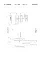
- FIG. 1is a block diagram showing one implementation of the present invention.
- FIG. 2is a partial schematic/partial block diagram showing in more detail the leadless monitoring device shown in FIG. 1.
- FIG. 3is a schematic diagram showing in more detail the RF-to-DC converter shown in FIG. 2.
- FIG. 1shows an exemplary embodiment of the present invention.
- a leadless monitoring device 20which is described in more detail below in connection with the description of FIG. 2, is arranged to sense a physiological condition of a patient 22.
- most of the components of leadless monitoring device 20are included within a package that is approximately the size of a conventional ECG electrode, e.g., less than one inch in diameter and less than one-eighth of an inch thick, and is attached to patient 22 in a similar manner as an ECG electrode. Leadless monitoring device therefore may be used without significantly discomforting patient 22.
- a patient monitoring system 54which includes a transmitter 24, a receiver 26, a demodulator 28, and a display 30.
- Patient monitoring system 54communicates with leadless monitoring device 20 via electromagnetic (EM) waves, preferably in the radio-frequency (RF) range, as explained below.
- EMelectromagnetic
- RFradio-frequency
- Transmitter 24is configured to emit an RF signal via an antenna 32. As shown in FIG. 1, transmitter 24 and antenna 32 are arranged such that a portion of the RF energy emitted by antenna 32 radiates in the general direction of leadless monitoring device 20.
- transmitter 24may be any simple continuous-wave (CW) signal generator.
- transmitter 24may include a signal generator such as model number HP 8656B manufactured by Hewlett-Packard Company.
- transmitter 24may be configured to emit an RF signal at a selected frequency between 300 and 900 megahertz (MHZ) and at a power level between -10 dBm and +10 dBm.
- MHZmegahertz
- the frequency and power level of the electromagnetic signal emitted by transmitter 24are not critical, however.
- Leadless monitoring device 20receives the RF signal emitted by transmitter 24 and re-radiates the RF signal such that information generated by the physiological transducer (included in leadless monitoring device 20) modulates the re-radiated RF signal.
- this informationis a digital data stream representing the amplitude of a potential difference measured by a pair of ECG electrodes, and the amplitude of the re-radiated RF signal is modulated according to state changes of the digital bit-stream, i.e., it is an amplitude-modulated (AM) signal.
- AMamplitude-modulated
- the re-radiated RF signalmay be mixed with an analog signal representing a physiological condition to produce a frequency-modulated (FM) signal, may be modulated using known phase-modulation (PM) techniques, or may be modulated in any other manner known to those skilled in the art.
- FMfrequency-modulated
- PMphase-modulation
- Receiver 26is configured to receive, via antenna 34, the RF signal re-radiated by leadless monitoring device 20.
- antennas 32 and 34may be replaced with a single antenna and this antenna may be coupled to transmitter 24 and receiver 26 through a mixer.
- Demodulator 28is coupled to receiver 26 and is configured to demodulate the RF signal received by receiver 26 to recover the information modulated onto the RF signal by leadless monitoring device 20.
- Display 30is coupled to demodulator 28 and displays the information recovered by demodulator 28. It should be appreciated that display 30 is only an example of a device that could make use of the output signal of demodulator 28 and that other devices also may use this signal for other useful purposes. For example, a central nurse station may analyze the output signal of demodulator 28 to detect anomalies in the physiological condition of a patient and generate alarms in response to the detection of such anomalies. Alternatively, the signal may be processed so as to extract useful information and such information may be logged into a database at a central location.
- receiver 26, demodulator 28 and display 30all are included in an RF Communications Test Set, e.g., model number HP8920A manufactured by Hewlett-Packard Company.
- HP8920A Test Setmay be set to operate in Duplex mode, and may be configured for AM demodulation with an intermediate frequency (IF) bandwidth of 230 kilohertz (kHz).
- IFintermediate frequency
- FIG. 2shows an exemplary embodiment of leadless monitoring device 20.
- leadless monitoring device 20includes a physiological transducer 45 (including a pair of ECG electrodes 46A and 46B), an ECG front-end 44, an RF-to-DC converter 52, and a transponder 58.
- Transducer 45 and ECG front-end 44are well known to those skilled in the art.
- Each of ECG electrodes 46A and 46Bmay include a cloth patch, approximately one inch in diameter, having an adhesive substance on one side to permit it to be attached to a patient.
- a small metal button adapted to have another metal fastener mate with the buttonmay be attached to the patch, and a gel substance may be placed on the same side of the patch as the adhesive to provide conductivity between the button and the skin of the patient.
- ECG front-end 44, RF-to-DC converter 52 and transponder 58all may be included on the non-adhesive surface of one of the pair of ECG electrodes 46A and 46B, and a wired lead from the other (standard) electrode may be fed to the electrode having the active components on it.
- This deviceis only slightly larger than the electrodes themselves. Because this embodiment of leadless monitoring device 20 may be constructed at a minimal cost, it may be disposed of after being used on a single patient. Therefore, in such an embodiment, sterilization of the devices need not be a concern.
- ECG front-end 44includes a differential amplifier 48 and an analog-to-digital converter (ADC) 50. As shown, an output of amplifier 48 feeds an analog input of ADC 50.
- ADC 50includes a 12 bit delta-sigma ADC preceded by an antialiasing filter.
- the active components of leadless monitoring device 20, i.e., amplifier 48 and ADC 50,are powered from DC outputs 60 and 62 of RF-to-DC converter 52, which is described in more detail below. It should be understood, however, that any other power source, e.g., a battery may be used to provide power to active components of ECG front-end 44. Alternatively, an ECG front-end using only passive components may be employed, in which case a power source such as RF-to-DC converter 52 is unnecessary.
- transponder 58includes an antenna 36 and a diode 38.
- a digital output of ADC 50is connected to a node 40, which is a connection point of antenna 36 and the anode of diode 38.
- the cathode of diode 38is connected to a ground node 42.
- diode 38is a zero-bias diode, e.g., model number HP5802 manufactured by Hewlett-Packard Company
- antenna 36is a thirty-three centimeter (cm) end-fed monopole antenna.
- the ideal length of antenna 36is dependent on the frequency at which transmitter 24 (shown in FIG. 1) is operating.
- antenna 36ideally should be approximately one-fourth as long as a wavelength of an RF wave from transmitter 24 (shown in FIG. 1). It should be appreciated, however, that this antenna/diode implementation of transponder 58 is only one example of a transponder that may be employed according to the invention, and any other transponder arrangement that performs a similar function alternatively may be employed. For example, a one-half wave center-fed dipole with a diode interposed between its two end nodes may be used instead of the monopole antenna shown in FIG. 2.
- antenna 36constitutes the outer conductor of a coaxial cable extending between a first ECG electrode, e.g., ECG electrode 46A, and a second ECG electrode, e.g., ECG electrode 46B, on which ECG front-end 44, RF-to-DC converter 52 and transponder 58 are mounted.
- the inner conductor of this coaxial cablemay be used to carry an electronic signal from the first ECG electrode to one of the inputs of ECG front end 44 (mounted on the second ECG electrode).
- ECG electrodes 46A and 46B of transducer 45are connected to opposite polarity inputs of differential amplifier 48. Therefore, the differential voltage between electrodes 46A and 46B determines the serial digital output stream of ADC 50. Because diode 38 is connected between the output of ADC 50 and ground, when the output of ADC 50 is in a high state, e.g., is at approximately two volts, diode 38 is turned on, and when the output of ADC 50 is in a low state, e.g., is at zero volts, diode 38 is turned off.
- diode 38This turning on and off of diode 38, in turn, affects the impedance of antenna 36 so that a significantly greater portion of any RF energy received by antenna 36 is re-radiated (i.e., reflected) by transponder 58 when diode 38 is turned off than when it is turned on. In other words, when diode 38 is turned on, a large portion of the RF energy received by antenna 36 will be shunted to ground node 42.
- the RF signal re-radiated by transponder 58is modulated (i.e., its amplitude is modulated) by a signal (i.e., the digital bit-stream output by ADC 50) representing an output signal of a physiological transducer (i.e., a differential voltage sensed between ECG electrodes 46A and 46B).
- a signali.e., the digital bit-stream output by ADC 50
- a physiological transduceri.e., a differential voltage sensed between ECG electrodes 46A and 46B
- the RF signalmay be in any suitable frequency range
- the RF signal re-radiated by transponder 58may be modulated using any known modulation technique
- the signal representing the output signal of transducer 45need not be digital, and may include the output signal of the transducer itself, e.g., when FM modulation of the re-radiated RF signal is employed
- transducer 45may be any device(s) known to those skilled in the art for generating a signal indicative of a physiological condition.
- transponder 58receives and re-radiates the RF signal from transmitter 24 at the same frequency.
- a frequency shifting circuite.g., a frequency divider or doubler circuit, may be used within leadless monitoring device 20 so that the frequency of the RF signal re-radiated from transponder 58 is different from the received frequency.
- FIG. 3shows a schematic diagram of one embodiment of RF-to-DC converter 52.
- RF-to-DC converter circuit 52includes an inductor L and a capacitor C1 connected in parallel.
- One end of these parallel-connected input devices (L and C1)is connected to the end of a half-wave single-end fed antenna 56, and the other end is connected to ground.
- Capacitor C1is variable to permit the circuit to be tuned to adjust the RF signal frequency range to which the device is sensitive.
- Each of diodes D1 and D2is connected (in an opposite polarity) to the end of antenna 56 so that any received RF signal that passes the input devices L and C1 is half-wave rectified by them.
- Capacitors C2 and C3are connected between ground and diodes D1 and D2, respectively, and storage capacitor C4 and resistor R are parallel-connected between the non-grounded electrodes of capacitors C2 and C3, to integrate and store the rectified one-half wave signals from diodes D1 and D2.
- the charge stored on capacitor C4then may be used to drive DC power supply leads 60 and 62.
- power supply leads 60 and 62may be used to power active components of ECG front-end 44, e.g., amplifier 48 and ADC 50.
- antenna 56 and antenna 58may constitute the same antenna, instead of each of them constituting separate antennas as shown in FIGS. 2 and 3.
- RF-to-DC converter 52shown in FIG. 3 is merely exemplary of the many circuits known to those skilled in the art for converting an RF signal to DC power.
- any other power sourcesuch as a battery, may be employed to provide power to active components of leadless monitoring device 20, or leadless monitoring device 20 may use only passive components (eliminating completely the need for a power source) without departing from the scope of the invention.
- the apparatus described hereinovercomes many of the drawbacks and disadvantages of prior art patient monitoring systems. Because the apparatus attached to the patient does not require a battery-operated transmitter, it is significantly less bulky, lighter and less costly than prior art telemetry units. Additionally, because the apparatus is wireless, cable-clutter is reduced dramatically over prior art cable-connected monitoring systems, thereby reducing or eliminating the above-noted drawbacks of such systems. Hence, a light-weight, low-cost, and reliable device is provided for monitoring the physiological condition(s) of patients.
Landscapes
- Health & Medical Sciences (AREA)
- Life Sciences & Earth Sciences (AREA)
- Engineering & Computer Science (AREA)
- Biomedical Technology (AREA)
- Medical Informatics (AREA)
- Computer Networks & Wireless Communication (AREA)
- Biophysics (AREA)
- Pathology (AREA)
- Physiology (AREA)
- Heart & Thoracic Surgery (AREA)
- Physics & Mathematics (AREA)
- Molecular Biology (AREA)
- Surgery (AREA)
- Animal Behavior & Ethology (AREA)
- General Health & Medical Sciences (AREA)
- Public Health (AREA)
- Veterinary Medicine (AREA)
- Measurement And Recording Of Electrical Phenomena And Electrical Characteristics Of The Living Body (AREA)
- Measuring And Recording Apparatus For Diagnosis (AREA)
Abstract
Description
Claims (25)
Priority Applications (1)
| Application Number | Priority Date | Filing Date | Title |
|---|---|---|---|
| US09/082,094US6132371A (en) | 1998-05-20 | 1998-05-20 | Leadless monitoring of physiological conditions |
Applications Claiming Priority (1)
| Application Number | Priority Date | Filing Date | Title |
|---|---|---|---|
| US09/082,094US6132371A (en) | 1998-05-20 | 1998-05-20 | Leadless monitoring of physiological conditions |
Publications (1)
| Publication Number | Publication Date |
|---|---|
| US6132371Atrue US6132371A (en) | 2000-10-17 |
Family
ID=22169033
Family Applications (1)
| Application Number | Title | Priority Date | Filing Date |
|---|---|---|---|
| US09/082,094Expired - LifetimeUS6132371A (en) | 1998-05-20 | 1998-05-20 | Leadless monitoring of physiological conditions |
Country Status (1)
| Country | Link |
|---|---|
| US (1) | US6132371A (en) |
Cited By (90)
| Publication number | Priority date | Publication date | Assignee | Title |
|---|---|---|---|---|
| US20020120184A1 (en)* | 2000-02-28 | 2002-08-29 | Beck Eric C. | Method and system for non-invasive measurement of prescribed characteristics of a subject |
| US20030181817A1 (en)* | 2002-03-25 | 2003-09-25 | Yasuhiro Mori | Vital sign detection sensor and sensor controlling device |
| US6668197B1 (en) | 1998-07-22 | 2003-12-23 | Imperial College Innovations Limited | Treatment using implantable devices |
| US6682480B1 (en)* | 1998-07-22 | 2004-01-27 | Imperial College Innovations Limited | Monitoring treatment using implantable telemetric sensors |
| US6692446B2 (en)* | 2000-03-21 | 2004-02-17 | Radi Medical Systems Ab | Passive biotelemetry |
| US20040123667A1 (en)* | 2002-08-01 | 2004-07-01 | Mcgrath William R. | Remote-sensing method and device |
| US20050012597A1 (en)* | 2003-07-02 | 2005-01-20 | Anderson Peter Traneus | Wireless electromagnetic tracking system using a nonlinear passive transponder |
| US6945935B1 (en)* | 1999-03-04 | 2005-09-20 | Anthony Corry Sasse | Wireless sleep monitoring |
| US20060155589A1 (en)* | 2005-01-10 | 2006-07-13 | Welch Allyn, Inc. | Portable vital signs measurement instrument and method of use thereof |
| US20060290519A1 (en)* | 2005-06-22 | 2006-12-28 | Boate Alan R | Two-way wireless monitoring system and method |
| USD536795S1 (en) | 2005-01-10 | 2007-02-13 | Welch Allyn, Inc. | Vital signs monitor |
| USD536794S1 (en) | 2005-01-10 | 2007-02-13 | Welch Allyn, Inc. | Vital signs monitor |
| US20070106145A1 (en)* | 2005-10-11 | 2007-05-10 | Samsung Electronics Co., Ltd. | Accessories for remote monitoring |
| US20080018480A1 (en)* | 2006-07-20 | 2008-01-24 | Sham John C K | Remote body temperature monitoring device |
| US20080045832A1 (en)* | 2002-08-01 | 2008-02-21 | Mcgrath William R | Remote-sensing method and device |
| US20080074307A1 (en)* | 2006-05-17 | 2008-03-27 | Olga Boric-Lubecke | Determining presence and/or physiological motion of one or more subjects within a doppler radar system |
| US20080228047A1 (en)* | 2007-01-19 | 2008-09-18 | Sierra Scientific Instruments, Inc. | Micro-remote gastrointestinal physiological measurement device |
| US20090043177A1 (en)* | 2007-08-08 | 2009-02-12 | Lifescan, Inc. | Method for integrating facilitated blood flow and blood analyte monitoring |
| WO2009046214A1 (en)* | 2007-10-03 | 2009-04-09 | University Of Utah Research Foundation | Miniature wireless biomedical telemetry device |
| US20090130623A1 (en)* | 2007-11-20 | 2009-05-21 | Techdent Technologies Ltd. | Method and apparatus for effecting dental measurements using a body-contacting electrode |
| US20090203972A1 (en)* | 2006-06-01 | 2009-08-13 | Biancamed Ltd. | Apparatus, system, and method for monitoring physiological signs |
| US7583190B2 (en) | 2005-10-31 | 2009-09-01 | Abbott Diabetes Care Inc. | Method and apparatus for providing data communication in data monitoring and management systems |
| US7620437B2 (en) | 2005-06-03 | 2009-11-17 | Abbott Diabetes Care Inc. | Method and apparatus for providing rechargeable power in data monitoring and management systems |
| US20100036253A1 (en)* | 2008-08-05 | 2010-02-11 | Daniel Vezina | System and method for managing a patient |
| US7679407B2 (en)* | 2003-04-28 | 2010-03-16 | Abbott Diabetes Care Inc. | Method and apparatus for providing peak detection circuitry for data communication systems |
| US7727181B2 (en) | 2002-10-09 | 2010-06-01 | Abbott Diabetes Care Inc. | Fluid delivery device with autocalibration |
| US20100137698A1 (en)* | 2003-06-12 | 2010-06-03 | Abbott Diabetes Care Inc. | Method and Apparatus for Providing Power Management in Data Communication Systems |
| US20100152543A1 (en)* | 2008-09-24 | 2010-06-17 | Biancamed Ltd. | Contactless and minimal-contact monitoring of quality of life parameters for assessment and intervention |
| US20100168577A1 (en)* | 2008-08-05 | 2010-07-01 | Daniel Vezina | Peripheral ultrasound device |
| US7756561B2 (en) | 2005-09-30 | 2010-07-13 | Abbott Diabetes Care Inc. | Method and apparatus for providing rechargeable power in data monitoring and management systems |
| US20100179438A1 (en)* | 2006-11-01 | 2010-07-15 | Biancamed Limited | System and method for monitoring cardiorespiratory parameters |
| US7768408B2 (en) | 2005-05-17 | 2010-08-03 | Abbott Diabetes Care Inc. | Method and system for providing data management in data monitoring system |
| US20100204550A1 (en)* | 2009-02-06 | 2010-08-12 | Biancamed Limited | Apparatus, system and method for chronic disease monitoring |
| US20100234746A1 (en)* | 2006-02-15 | 2010-09-16 | Novosense Ab | System and method for wireless generation of standard ecg leads and an ecg sensing unit therefor |
| US7831447B2 (en) | 2001-03-30 | 2010-11-09 | Hill-Rom Services, Inc. | Healthcare computer system |
| US7922458B2 (en) | 2002-10-09 | 2011-04-12 | Abbott Diabetes Care Inc. | Variable volume, shape memory actuated insulin dispensing pump |
| US8026821B2 (en) | 2000-05-05 | 2011-09-27 | Hill-Rom Services, Inc. | System for monitoring caregivers and equipment at a patient location |
| US8029459B2 (en) | 2005-03-21 | 2011-10-04 | Abbott Diabetes Care Inc. | Method and system for providing integrated medication infusion and analyte monitoring system |
| US8047811B2 (en) | 2002-10-09 | 2011-11-01 | Abbott Diabetes Care Inc. | Variable volume, shape memory actuated insulin dispensing pump |
| US8082160B2 (en) | 2007-10-26 | 2011-12-20 | Hill-Rom Services, Inc. | System and method for collection and communication of data from multiple patient care devices |
| US8115635B2 (en) | 2005-02-08 | 2012-02-14 | Abbott Diabetes Care Inc. | RF tag on test strips, test strip vials and boxes |
| US8234128B2 (en) | 2002-04-30 | 2012-07-31 | Baxter International, Inc. | System and method for verifying medical device operational parameters |
| US20120274502A1 (en)* | 2011-04-29 | 2012-11-01 | Searete Llc | Personal electronic device with a micro-impulse radar |
| US20120274498A1 (en)* | 2011-04-29 | 2012-11-01 | Searete Llc | Personal electronic device providing enhanced user environmental awareness |
| US8344966B2 (en) | 2006-01-31 | 2013-01-01 | Abbott Diabetes Care Inc. | Method and system for providing a fault tolerant display unit in an electronic device |
| US8421606B2 (en) | 2004-08-02 | 2013-04-16 | Hill-Rom Services, Inc. | Wireless bed locating system |
| US8467972B2 (en) | 2009-04-28 | 2013-06-18 | Abbott Diabetes Care Inc. | Closed loop blood glucose control algorithm analysis |
| US8560082B2 (en) | 2009-01-30 | 2013-10-15 | Abbott Diabetes Care Inc. | Computerized determination of insulin pump therapy parameters using real time and retrospective data processing |
| US8579853B2 (en) | 2006-10-31 | 2013-11-12 | Abbott Diabetes Care Inc. | Infusion devices and methods |
| US8775196B2 (en) | 2002-01-29 | 2014-07-08 | Baxter International Inc. | System and method for notification and escalation of medical data |
| US8798934B2 (en) | 2009-07-23 | 2014-08-05 | Abbott Diabetes Care Inc. | Real time management of data relating to physiological control of glucose levels |
| US20150164379A1 (en)* | 2012-05-23 | 2015-06-18 | University Of Florida Research Foundation, Incorporated | Method and apparatus for detecting and/or analyzing motion using radar and multiple identifiable reflectors |
| US9103899B2 (en) | 2011-04-29 | 2015-08-11 | The Invention Science Fund I, Llc | Adaptive control of a personal electronic device responsive to a micro-impulse radar |
| US9142923B2 (en) | 2003-08-21 | 2015-09-22 | Hill-Rom Services, Inc. | Hospital bed having wireless data and locating capability |
| US9151834B2 (en) | 2011-04-29 | 2015-10-06 | The Invention Science Fund I, Llc | Network and personal electronic devices operatively coupled to micro-impulse radars |
| US9230421B2 (en) | 2000-05-05 | 2016-01-05 | Hill-Rom Services, Inc. | System for monitoring caregivers and equipment |
| US20160012711A1 (en)* | 2014-07-08 | 2016-01-14 | Honeywell International Inc. | System and Method Identifying Unevacuated Facility Residents During An Emergency Condition |
| USD764064S1 (en) | 2013-06-07 | 2016-08-16 | Guardsman Scientific, Inc. | Securing mechanism for a peripheral ultrasound device |
| USD787684S1 (en) | 2013-06-07 | 2017-05-23 | Guardsman Scientific, Inc. | Securing mechanism with a probe for a peripheral ultrasound device |
| USD787685S1 (en) | 2013-06-07 | 2017-05-23 | Guardsman Scientific, Inc. | Probe for a peripheral ultrasound device |
| WO2017157989A1 (en)* | 2016-03-16 | 2017-09-21 | Koninklijke Philips N.V. | A method, system and apparatus for measuring a physiological characteristic of a subject |
| US9833200B2 (en) | 2015-05-14 | 2017-12-05 | University Of Florida Research Foundation, Inc. | Low IF architectures for noncontact vital sign detection |
| US9924906B2 (en) | 2007-07-12 | 2018-03-27 | University Of Florida Research Foundation, Inc. | Random body movement cancellation for non-contact vital sign detection |
| US9955887B2 (en) | 2014-10-31 | 2018-05-01 | Irhythm Technologies, Inc. | Wearable monitor |
| US10001557B2 (en)* | 2013-03-13 | 2018-06-19 | Oki Electric Industry Co., Ltd. | State recognizing device, state recognizing method, and recording medium |
| US10016554B2 (en) | 2008-07-09 | 2018-07-10 | Baxter International Inc. | Dialysis system including wireless patient data |
| US10061899B2 (en) | 2008-07-09 | 2018-08-28 | Baxter International Inc. | Home therapy machine |
| US10173008B2 (en) | 2002-01-29 | 2019-01-08 | Baxter International Inc. | System and method for communicating with a dialysis machine through a network |
| US10271754B2 (en) | 2013-01-24 | 2019-04-30 | Irhythm Technologies, Inc. | Physiological monitoring device |
| US10347374B2 (en) | 2008-10-13 | 2019-07-09 | Baxter Corporation Englewood | Medication preparation system |
| US10360787B2 (en) | 2016-05-05 | 2019-07-23 | Hill-Rom Services, Inc. | Discriminating patient care communications system |
| US10405799B2 (en) | 2010-05-12 | 2019-09-10 | Irhythm Technologies, Inc. | Device features and design elements for long-term adhesion |
| US10646405B2 (en) | 2012-10-26 | 2020-05-12 | Baxter Corporation Englewood | Work station for medical dose preparation system |
| US10818387B2 (en) | 2014-12-05 | 2020-10-27 | Baxter Corporation Englewood | Dose preparation data analytics |
| US10971257B2 (en) | 2012-10-26 | 2021-04-06 | Baxter Corporation Englewood | Image acquisition for medical dose preparation system |
| US11051702B2 (en) | 2014-10-08 | 2021-07-06 | University Of Florida Research Foundation, Inc. | Method and apparatus for non-contact fast vital sign acquisition based on radar signal |
| US11083371B1 (en) | 2020-02-12 | 2021-08-10 | Irhythm Technologies, Inc. | Methods and systems for processing data via an executable file on a monitor to reduce the dimensionality of the data and encrypting the data being transmitted over the wireless network |
| US11107574B2 (en) | 2014-09-30 | 2021-08-31 | Baxter Corporation Englewood | Management of medication preparation with formulary management |
| US11246523B1 (en) | 2020-08-06 | 2022-02-15 | Irhythm Technologies, Inc. | Wearable device with conductive traces and insulator |
| US11350864B2 (en) | 2020-08-06 | 2022-06-07 | Irhythm Technologies, Inc. | Adhesive physiological monitoring device |
| US11367533B2 (en) | 2014-06-30 | 2022-06-21 | Baxter Corporation Englewood | Managed medical information exchange |
| US11495334B2 (en) | 2015-06-25 | 2022-11-08 | Gambro Lundia Ab | Medical device system and method having a distributed database |
| US11516183B2 (en) | 2016-12-21 | 2022-11-29 | Gambro Lundia Ab | Medical device system including information technology infrastructure having secure cluster domain supporting external domain |
| US11575673B2 (en) | 2014-09-30 | 2023-02-07 | Baxter Corporation Englewood | Central user management in a distributed healthcare information management system |
| US11948112B2 (en) | 2015-03-03 | 2024-04-02 | Baxter Corporation Engelwood | Pharmacy workflow management with integrated alerts |
| US12186241B2 (en) | 2021-01-22 | 2025-01-07 | Hill-Rom Services, Inc. | Time-based wireless pairing between a medical device and a wall unit |
| USD1063079S1 (en) | 2021-08-06 | 2025-02-18 | Irhythm Technologies, Inc. | Physiological monitoring device |
| US12279999B2 (en) | 2021-01-22 | 2025-04-22 | Hill-Rom Services, Inc. | Wireless configuration and authorization of a wall unit that pairs with a medical device |
| US12412644B2 (en) | 2014-10-24 | 2025-09-09 | Baxter Corporation Englewood | Automated exchange of healthcare information for fulfillment of medication doses |
| US12440111B2 (en) | 2024-02-14 | 2025-10-14 | Resmed Sensor Technologies Limited | Apparatus, system and method for chronic disease monitoring |
Citations (6)
| Publication number | Priority date | Publication date | Assignee | Title |
|---|---|---|---|---|
| US4635296A (en)* | 1985-02-22 | 1987-01-06 | Transkinetic Systems, Inc. | Wide bandwidth ultra high stability FM telemetry transmitter |
| US4827943A (en)* | 1986-09-23 | 1989-05-09 | Advanced Medical Technologies, Inc. | Portable, multi-channel, physiological data monitoring system |
| US5322034A (en)* | 1992-05-01 | 1994-06-21 | Iowa State University Research Foundation, Inc. | Livestock record system |
| US5445150A (en)* | 1991-11-18 | 1995-08-29 | General Electric Company | Invasive system employing a radiofrequency tracking system |
| US5499626A (en)* | 1992-05-01 | 1996-03-19 | Willham; Richard L. | Individual descriptive record system |
| US5704352A (en)* | 1995-11-22 | 1998-01-06 | Tremblay; Gerald F. | Implantable passive bio-sensor |
- 1998
- 1998-05-20USUS09/082,094patent/US6132371A/ennot_activeExpired - Lifetime
Patent Citations (6)
| Publication number | Priority date | Publication date | Assignee | Title |
|---|---|---|---|---|
| US4635296A (en)* | 1985-02-22 | 1987-01-06 | Transkinetic Systems, Inc. | Wide bandwidth ultra high stability FM telemetry transmitter |
| US4827943A (en)* | 1986-09-23 | 1989-05-09 | Advanced Medical Technologies, Inc. | Portable, multi-channel, physiological data monitoring system |
| US5445150A (en)* | 1991-11-18 | 1995-08-29 | General Electric Company | Invasive system employing a radiofrequency tracking system |
| US5322034A (en)* | 1992-05-01 | 1994-06-21 | Iowa State University Research Foundation, Inc. | Livestock record system |
| US5499626A (en)* | 1992-05-01 | 1996-03-19 | Willham; Richard L. | Individual descriptive record system |
| US5704352A (en)* | 1995-11-22 | 1998-01-06 | Tremblay; Gerald F. | Implantable passive bio-sensor |
Non-Patent Citations (16)
| Title |
|---|
| California Institute of Technology, Jet Propulsion Laboratory Technology Report, 19 pages, "Person-Locater System Based on Wristband Radio Transponders" (Dec., 1995). |
| California Institute of Technology, Jet Propulsion Laboratory Technology Report, 19 pages, Person Locater System Based on Wristband Radio Transponders (Dec., 1995).* |
| California Institute of Technology, Jet Propulsion Laboratory, 9 pages, first page includes "Phase I: Develop Proof of Concept; Phase II: Prepare and Field Test a Prototype Model; Phase III: Assist in the Development of the Commercial Prototype System and Assist in an Installation in a Local Jail Facility" (date unknown). |
| California Institute of Technology, Jet Propulsion Laboratory, 9 pages, first page includes Phase I: Develop Proof of Concept; Phase II: Prepare and Field Test a Prototype Model; Phase III: Assist in the Development of the Commercial Prototype System and Assist in an Installation in a Local Jail Facility (date unknown).* |
| Ishak, Waguih S. et al., "Surface-Acoustic-Wave Delay Lines and Transversal Filters," Hewlett Packard Journal, pp. 3-27 (Dec., 1981). |
| Ishak, Waguih S. et al., Surface Acoustic Wave Delay Lines and Transversal Filters, Hewlett Packard Journal, pp. 3 27 (Dec., 1981).* |
| Johnston, Ronald H. et al., University of Calgary, "A Biotelemetry System for Monitoring Heart Rates in Unrestrained Ungulates," Biotelemetry Patient Montig 7, pp 188-198 (1980). |
| Johnston, Ronald H. et al., University of Calgary, A Biotelemetry System for Monitoring Heart Rates in Unrestrained Ungulates, Biotelemetry Patient Montig 7, pp 188 198 (1980).* |
| NASA Tech Briefs (MSC 21501), 15 pages, Biomedical Telectrodes (1988).* |
| NASA Tech Briefs (MSC-21501), 15 pages, "Biomedical Telectrodes" (1988). |
| Seals J. et al., Georgia Institute of Technology, 8 pages, "An Electromagnetic-Based Non-Contact Vital Signs Monitor," (date unknown). |
| Seals J. et al., Georgia Institute of Technology, 8 pages, An Electromagnetic Based Non Contact Vital Signs Monitor, (date unknown).* |
| Sugiura, T. et al., "Microcomputer-Based Telemetry System for Heart Rate and Blood Temperature in Dogs," pp. 551-567 (date unknown). |
| Sugiura, T. et al., Microcomputer Based Telemetry System for Heart Rate and Blood Temperature in Dogs, pp. 551 567 (date unknown).* |
| Viewgraphs re: Backscatter Technology, 18 pages, first page titled "Infostation System Architecture," private communication from Wireless Information Network Laboratory (WINLAB), Rutgers University, NJ (date unknown). |
| Viewgraphs re: Backscatter Technology, 18 pages, first page titled Infostation System Architecture, private communication from Wireless Information Network Laboratory (WINLAB), Rutgers University, NJ (date unknown).* |
Cited By (222)
| Publication number | Priority date | Publication date | Assignee | Title |
|---|---|---|---|---|
| US6668197B1 (en) | 1998-07-22 | 2003-12-23 | Imperial College Innovations Limited | Treatment using implantable devices |
| US6682480B1 (en)* | 1998-07-22 | 2004-01-27 | Imperial College Innovations Limited | Monitoring treatment using implantable telemetric sensors |
| US6945935B1 (en)* | 1999-03-04 | 2005-09-20 | Anthony Corry Sasse | Wireless sleep monitoring |
| US8052600B2 (en)* | 2000-02-28 | 2011-11-08 | Alcatel Lucent | Method and system for non-invasive measurement of prescribed characteristics of a subject |
| US20020120184A1 (en)* | 2000-02-28 | 2002-08-29 | Beck Eric C. | Method and system for non-invasive measurement of prescribed characteristics of a subject |
| US6692446B2 (en)* | 2000-03-21 | 2004-02-17 | Radi Medical Systems Ab | Passive biotelemetry |
| US8487774B2 (en) | 2000-05-05 | 2013-07-16 | Hill-Rom Services, Inc. | System for monitoring caregivers and equipment |
| US9230421B2 (en) | 2000-05-05 | 2016-01-05 | Hill-Rom Services, Inc. | System for monitoring caregivers and equipment |
| US9666061B2 (en) | 2000-05-05 | 2017-05-30 | Hill-Rom Services, Inc. | System for monitoring caregivers and equipment |
| US8766804B2 (en) | 2000-05-05 | 2014-07-01 | Hill-Rom Services, Inc. | System for monitoring caregivers and equipment |
| US8258965B2 (en) | 2000-05-05 | 2012-09-04 | Hill-Rom Services, Inc. | System for monitoring caregivers and equipment at a patient location |
| US8026821B2 (en) | 2000-05-05 | 2011-09-27 | Hill-Rom Services, Inc. | System for monitoring caregivers and equipment at a patient location |
| US7831447B2 (en) | 2001-03-30 | 2010-11-09 | Hill-Rom Services, Inc. | Healthcare computer system |
| US10556062B2 (en) | 2002-01-29 | 2020-02-11 | Baxter International Inc. | Electronic medication order transfer and processing methods and apparatus |
| US8775196B2 (en) | 2002-01-29 | 2014-07-08 | Baxter International Inc. | System and method for notification and escalation of medical data |
| US10173008B2 (en) | 2002-01-29 | 2019-01-08 | Baxter International Inc. | System and method for communicating with a dialysis machine through a network |
| EP1350460A3 (en)* | 2002-03-25 | 2004-03-10 | Matsushita Electric Industrial Co., Ltd. | Vital sign detection sensor and sensor controlling device |
| US20030181817A1 (en)* | 2002-03-25 | 2003-09-25 | Yasuhiro Mori | Vital sign detection sensor and sensor controlling device |
| US8234128B2 (en) | 2002-04-30 | 2012-07-31 | Baxter International, Inc. | System and method for verifying medical device operational parameters |
| US7272431B2 (en) | 2002-08-01 | 2007-09-18 | California Institute Of Technology | Remote-sensing method and device |
| US20080045832A1 (en)* | 2002-08-01 | 2008-02-21 | Mcgrath William R | Remote-sensing method and device |
| US7811234B2 (en) | 2002-08-01 | 2010-10-12 | California Institute Of Technology | Remote-sensing method and device |
| US20040123667A1 (en)* | 2002-08-01 | 2004-07-01 | Mcgrath William R. | Remote-sensing method and device |
| US8047812B2 (en) | 2002-10-09 | 2011-11-01 | Abbott Diabetes Care Inc. | Variable volume, shape memory actuated insulin dispensing pump |
| US8029250B2 (en) | 2002-10-09 | 2011-10-04 | Abbott Diabetes Care Inc. | Variable volume, shape memory actuated insulin dispensing pump |
| US7993108B2 (en) | 2002-10-09 | 2011-08-09 | Abbott Diabetes Care Inc. | Variable volume, shape memory actuated insulin dispensing pump |
| US7993109B2 (en) | 2002-10-09 | 2011-08-09 | Abbott Diabetes Care Inc. | Variable volume, shape memory actuated insulin dispensing pump |
| US7922458B2 (en) | 2002-10-09 | 2011-04-12 | Abbott Diabetes Care Inc. | Variable volume, shape memory actuated insulin dispensing pump |
| US7753874B2 (en)* | 2002-10-09 | 2010-07-13 | Abbott Diabetes Care Inc. | Fluid delivery device with autocalibration |
| US7727181B2 (en) | 2002-10-09 | 2010-06-01 | Abbott Diabetes Care Inc. | Fluid delivery device with autocalibration |
| US8029245B2 (en) | 2002-10-09 | 2011-10-04 | Abbott Diabetes Care Inc. | Variable volume, shape memory actuated insulin dispensing pump |
| US7766864B2 (en)* | 2002-10-09 | 2010-08-03 | Abbott Diabetes Care Inc. | Fluid delivery device with autocalibration |
| US8047811B2 (en) | 2002-10-09 | 2011-11-01 | Abbott Diabetes Care Inc. | Variable volume, shape memory actuated insulin dispensing pump |
| US8343093B2 (en) | 2002-10-09 | 2013-01-01 | Abbott Diabetes Care Inc. | Fluid delivery device with autocalibration |
| US7753873B2 (en)* | 2002-10-09 | 2010-07-13 | Abbott Diabetes Care Inc. | Fluid delivery device with autocalibration |
| US8512246B2 (en) | 2003-04-28 | 2013-08-20 | Abbott Diabetes Care Inc. | Method and apparatus for providing peak detection circuitry for data communication systems |
| US7679407B2 (en)* | 2003-04-28 | 2010-03-16 | Abbott Diabetes Care Inc. | Method and apparatus for providing peak detection circuitry for data communication systems |
| US8906307B2 (en) | 2003-06-12 | 2014-12-09 | Abbott Diabetes Care Inc. | Apparatus for providing power management in data communication systems |
| US8273295B2 (en) | 2003-06-12 | 2012-09-25 | Abbott Diabetes Care Inc. | Apparatus for providing power management in data communication systems |
| US9109926B2 (en) | 2003-06-12 | 2015-08-18 | Abbott Diabetes Care Inc. | Method and apparatus for providing power management in data communication systems |
| US20100137698A1 (en)* | 2003-06-12 | 2010-06-03 | Abbott Diabetes Care Inc. | Method and Apparatus for Providing Power Management in Data Communication Systems |
| US8071028B2 (en) | 2003-06-12 | 2011-12-06 | Abbott Diabetes Care Inc. | Method and apparatus for providing power management in data communication systems |
| US20050012597A1 (en)* | 2003-07-02 | 2005-01-20 | Anderson Peter Traneus | Wireless electromagnetic tracking system using a nonlinear passive transponder |
| US9572737B2 (en) | 2003-08-21 | 2017-02-21 | Hill-Rom Services, Inc. | Hospital bed having communication modules |
| US9142923B2 (en) | 2003-08-21 | 2015-09-22 | Hill-Rom Services, Inc. | Hospital bed having wireless data and locating capability |
| US10206837B2 (en) | 2003-08-21 | 2019-02-19 | Hill-Rom Services, Inc. | Hospital bed and room communication modules |
| US9925104B2 (en) | 2003-08-21 | 2018-03-27 | Hill-Rom Services, Inc. | Hospital bed and room communication modules |
| US8421606B2 (en) | 2004-08-02 | 2013-04-16 | Hill-Rom Services, Inc. | Wireless bed locating system |
| USD536794S1 (en) | 2005-01-10 | 2007-02-13 | Welch Allyn, Inc. | Vital signs monitor |
| USD536795S1 (en) | 2005-01-10 | 2007-02-13 | Welch Allyn, Inc. | Vital signs monitor |
| US20060155589A1 (en)* | 2005-01-10 | 2006-07-13 | Welch Allyn, Inc. | Portable vital signs measurement instrument and method of use thereof |
| US8115635B2 (en) | 2005-02-08 | 2012-02-14 | Abbott Diabetes Care Inc. | RF tag on test strips, test strip vials and boxes |
| US8358210B2 (en) | 2005-02-08 | 2013-01-22 | Abbott Diabetes Care Inc. | RF tag on test strips, test strip vials and boxes |
| US8542122B2 (en) | 2005-02-08 | 2013-09-24 | Abbott Diabetes Care Inc. | Glucose measurement device and methods using RFID |
| US8223021B2 (en) | 2005-02-08 | 2012-07-17 | Abbott Diabetes Care Inc. | RF tag on test strips, test strip vials and boxes |
| US8390455B2 (en) | 2005-02-08 | 2013-03-05 | Abbott Diabetes Care Inc. | RF tag on test strips, test strip vials and boxes |
| US8343092B2 (en) | 2005-03-21 | 2013-01-01 | Abbott Diabetes Care Inc. | Method and system for providing integrated medication infusion and analyte monitoring system |
| US8029459B2 (en) | 2005-03-21 | 2011-10-04 | Abbott Diabetes Care Inc. | Method and system for providing integrated medication infusion and analyte monitoring system |
| US8029460B2 (en) | 2005-03-21 | 2011-10-04 | Abbott Diabetes Care Inc. | Method and system for providing integrated medication infusion and analyte monitoring system |
| US9332944B2 (en) | 2005-05-17 | 2016-05-10 | Abbott Diabetes Care Inc. | Method and system for providing data management in data monitoring system |
| US10206611B2 (en) | 2005-05-17 | 2019-02-19 | Abbott Diabetes Care Inc. | Method and system for providing data management in data monitoring system |
| US8089363B2 (en) | 2005-05-17 | 2012-01-03 | Abbott Diabetes Care Inc. | Method and system for providing data management in data monitoring system |
| US7884729B2 (en) | 2005-05-17 | 2011-02-08 | Abbott Diabetes Care Inc. | Method and system for providing data management in data monitoring system |
| US9750440B2 (en) | 2005-05-17 | 2017-09-05 | Abbott Diabetes Care Inc. | Method and system for providing data management in data monitoring system |
| US8653977B2 (en) | 2005-05-17 | 2014-02-18 | Abbott Diabetes Care Inc. | Method and system for providing data management in data monitoring system |
| US7768408B2 (en) | 2005-05-17 | 2010-08-03 | Abbott Diabetes Care Inc. | Method and system for providing data management in data monitoring system |
| US8471714B2 (en) | 2005-05-17 | 2013-06-25 | Abbott Diabetes Care Inc. | Method and system for providing data management in data monitoring system |
| US8112138B2 (en) | 2005-06-03 | 2012-02-07 | Abbott Diabetes Care Inc. | Method and apparatus for providing rechargeable power in data monitoring and management systems |
| US7620437B2 (en) | 2005-06-03 | 2009-11-17 | Abbott Diabetes Care Inc. | Method and apparatus for providing rechargeable power in data monitoring and management systems |
| US20060290519A1 (en)* | 2005-06-22 | 2006-12-28 | Boate Alan R | Two-way wireless monitoring system and method |
| US7756561B2 (en) | 2005-09-30 | 2010-07-13 | Abbott Diabetes Care Inc. | Method and apparatus for providing rechargeable power in data monitoring and management systems |
| US20070106145A1 (en)* | 2005-10-11 | 2007-05-10 | Samsung Electronics Co., Ltd. | Accessories for remote monitoring |
| US8882667B2 (en)* | 2005-10-11 | 2014-11-11 | Samsung Electronics Co., Ltd. | Accessories for remote monitoring |
| US7583190B2 (en) | 2005-10-31 | 2009-09-01 | Abbott Diabetes Care Inc. | Method and apparatus for providing data communication in data monitoring and management systems |
| US8638220B2 (en) | 2005-10-31 | 2014-01-28 | Abbott Diabetes Care Inc. | Method and apparatus for providing data communication in data monitoring and management systems |
| US7948370B2 (en) | 2005-10-31 | 2011-05-24 | Abbott Diabetes Care Inc. | Method and apparatus for providing data communication in data monitoring and management systems |
| US8344966B2 (en) | 2006-01-31 | 2013-01-01 | Abbott Diabetes Care Inc. | Method and system for providing a fault tolerant display unit in an electronic device |
| US9364150B2 (en) | 2006-02-15 | 2016-06-14 | Novosense Ab | System and method for wireless generation of standard ECG leads and an ECG sensing unit therefor |
| US20100234746A1 (en)* | 2006-02-15 | 2010-09-16 | Novosense Ab | System and method for wireless generation of standard ecg leads and an ecg sensing unit therefor |
| US8315695B2 (en) | 2006-02-15 | 2012-11-20 | Novosense Ab | System and method for wireless generation of standard ECG leads and an ECG sensing unit therefor |
| US20080077015A1 (en)* | 2006-05-17 | 2008-03-27 | Olga Boric-Lubecke | Determining presence and/or physiological motion of one or more subjects with multiple receiver Doppler radar systems |
| US20080074307A1 (en)* | 2006-05-17 | 2008-03-27 | Olga Boric-Lubecke | Determining presence and/or physiological motion of one or more subjects within a doppler radar system |
| US20080119716A1 (en)* | 2006-05-17 | 2008-05-22 | Olga Boric-Lubecke | Determining presence and/or physiological motion of one or more subjects with quadrature doppler radar receiver systems |
| US12324652B2 (en) | 2006-06-01 | 2025-06-10 | Resmed Sensor Technologies Limited | Apparatus, system, and method for monitoring physiological signs |
| US20090203972A1 (en)* | 2006-06-01 | 2009-08-13 | Biancamed Ltd. | Apparatus, system, and method for monitoring physiological signs |
| US8562526B2 (en) | 2006-06-01 | 2013-10-22 | Resmed Sensor Technologies Limited | Apparatus, system, and method for monitoring physiological signs |
| US11690519B2 (en) | 2006-06-01 | 2023-07-04 | Resmed Sensor Technologies Limited | Apparatus, system, and method for monitoring physiological signs |
| US10729332B2 (en) | 2006-06-01 | 2020-08-04 | Resmed Sensor Technologies Limited | Apparatus, system, and method for monitoring physiological signs |
| US20080018480A1 (en)* | 2006-07-20 | 2008-01-24 | Sham John C K | Remote body temperature monitoring device |
| US11508476B2 (en) | 2006-10-31 | 2022-11-22 | Abbott Diabetes Care, Inc. | Infusion devices and methods |
| US9064107B2 (en) | 2006-10-31 | 2015-06-23 | Abbott Diabetes Care Inc. | Infusion devices and methods |
| US12073941B2 (en) | 2006-10-31 | 2024-08-27 | Abbott Diabetes Care Inc. | Infusion device and methods |
| US8579853B2 (en) | 2006-10-31 | 2013-11-12 | Abbott Diabetes Care Inc. | Infusion devices and methods |
| US11837358B2 (en) | 2006-10-31 | 2023-12-05 | Abbott Diabetes Care Inc. | Infusion devices and methods |
| US10007759B2 (en) | 2006-10-31 | 2018-06-26 | Abbott Diabetes Care Inc. | Infusion devices and methods |
| US11043300B2 (en) | 2006-10-31 | 2021-06-22 | Abbott Diabetes Care Inc. | Infusion devices and methods |
| US20100179438A1 (en)* | 2006-11-01 | 2010-07-15 | Biancamed Limited | System and method for monitoring cardiorespiratory parameters |
| US8834364B2 (en) | 2006-11-01 | 2014-09-16 | Resmed Sensor Technologies Limited | System and method for monitoring cardiorespiratory parameters |
| US12226190B2 (en)* | 2006-11-01 | 2025-02-18 | Resmed Sensor Technologies Limited | System and method for monitoring cardiorespiratory parameters |
| US20210338086A1 (en)* | 2006-11-01 | 2021-11-04 | Resmed Sensor Technologies Limited | System and method for monitoring cardiorespiratory parameters |
| US10893811B2 (en) | 2006-11-01 | 2021-01-19 | Resmed Sensor Technologies Limited | System and method for monitoring cardiorespiratory parameters |
| US20080228047A1 (en)* | 2007-01-19 | 2008-09-18 | Sierra Scientific Instruments, Inc. | Micro-remote gastrointestinal physiological measurement device |
| US9125588B2 (en) | 2007-01-19 | 2015-09-08 | Sierra Scientific Instruments, Inc. | Micro-remote gastrointestinal physiological measurement device |
| US9924906B2 (en) | 2007-07-12 | 2018-03-27 | University Of Florida Research Foundation, Inc. | Random body movement cancellation for non-contact vital sign detection |
| US20090043177A1 (en)* | 2007-08-08 | 2009-02-12 | Lifescan, Inc. | Method for integrating facilitated blood flow and blood analyte monitoring |
| US7747302B2 (en)* | 2007-08-08 | 2010-06-29 | Lifescan, Inc. | Method for integrating facilitated blood flow and blood analyte monitoring |
| US20100222686A1 (en)* | 2007-10-03 | 2010-09-02 | University Of Utah Research Foundation | Miniature wireless biomedical telemetry device |
| WO2009046214A1 (en)* | 2007-10-03 | 2009-04-09 | University Of Utah Research Foundation | Miniature wireless biomedical telemetry device |
| US9474461B2 (en) | 2007-10-03 | 2016-10-25 | University Of Utah Research Foundation | Miniature wireless biomedical telemetry device |
| US11031130B2 (en) | 2007-10-26 | 2021-06-08 | Hill-Rom Services, Inc. | Patient support apparatus having data collection and communication capability |
| US8082160B2 (en) | 2007-10-26 | 2011-12-20 | Hill-Rom Services, Inc. | System and method for collection and communication of data from multiple patient care devices |
| US8756078B2 (en) | 2007-10-26 | 2014-06-17 | Hill-Rom Services, Inc. | System and method for collection and communication of data from multiple patient care devices |
| US9734293B2 (en) | 2007-10-26 | 2017-08-15 | Hill-Rom Services, Inc. | System and method for association of patient care devices to a patient |
| US20090130623A1 (en)* | 2007-11-20 | 2009-05-21 | Techdent Technologies Ltd. | Method and apparatus for effecting dental measurements using a body-contacting electrode |
| US10224117B2 (en) | 2008-07-09 | 2019-03-05 | Baxter International Inc. | Home therapy machine allowing patient device program selection |
| US10272190B2 (en) | 2008-07-09 | 2019-04-30 | Baxter International Inc. | Renal therapy system including a blood pressure monitor |
| US11918721B2 (en) | 2008-07-09 | 2024-03-05 | Baxter International Inc. | Dialysis system having adaptive prescription management |
| US10646634B2 (en) | 2008-07-09 | 2020-05-12 | Baxter International Inc. | Dialysis system and disposable set |
| US10095840B2 (en) | 2008-07-09 | 2018-10-09 | Baxter International Inc. | System and method for performing renal therapy at a home or dwelling of a patient |
| US11311658B2 (en) | 2008-07-09 | 2022-04-26 | Baxter International Inc. | Dialysis system having adaptive prescription generation |
| US10068061B2 (en) | 2008-07-09 | 2018-09-04 | Baxter International Inc. | Home therapy entry, modification, and reporting system |
| US10061899B2 (en) | 2008-07-09 | 2018-08-28 | Baxter International Inc. | Home therapy machine |
| US10016554B2 (en) | 2008-07-09 | 2018-07-10 | Baxter International Inc. | Dialysis system including wireless patient data |
| US20100168577A1 (en)* | 2008-08-05 | 2010-07-01 | Daniel Vezina | Peripheral ultrasound device |
| US20100036253A1 (en)* | 2008-08-05 | 2010-02-11 | Daniel Vezina | System and method for managing a patient |
| US8876720B2 (en) | 2008-08-05 | 2014-11-04 | Guardsman Scientific, Inc. | Peripheral ultrasound device providing pivotal adjustment of an imaging mechanism about two axes |
| US8348847B2 (en) | 2008-08-05 | 2013-01-08 | Guardsman Scientific, Inc. | System and method for managing a patient |
| US20110178377A1 (en)* | 2008-09-24 | 2011-07-21 | Biancamed Ltd. | Contactless and minimal-contact monitoring of quality of life parameters for assessment and intervention |
| US10885152B2 (en) | 2008-09-24 | 2021-01-05 | Resmed Sensor Technologies Limited | Systems and methods for monitoring quality of life parameters using non-contact sensors |
| US20100152543A1 (en)* | 2008-09-24 | 2010-06-17 | Biancamed Ltd. | Contactless and minimal-contact monitoring of quality of life parameters for assessment and intervention |
| US9223935B2 (en) | 2008-09-24 | 2015-12-29 | Resmed Sensor Technologies Limited | Contactless and minimal-contact monitoring of quality of life parameters for assessment and intervention |
| US10891356B2 (en) | 2008-09-24 | 2021-01-12 | Resmed Sensor Technologies Limited | Contactless and minimal-contact monitoring of quality of life parameters for assessment and intervention |
| US10347374B2 (en) | 2008-10-13 | 2019-07-09 | Baxter Corporation Englewood | Medication preparation system |
| US8560082B2 (en) | 2009-01-30 | 2013-10-15 | Abbott Diabetes Care Inc. | Computerized determination of insulin pump therapy parameters using real time and retrospective data processing |
| US10799126B2 (en) | 2009-02-06 | 2020-10-13 | Resmed Sensor Technologies Limited | Apparatus, system and method for chronic disease monitoring |
| US20100204550A1 (en)* | 2009-02-06 | 2010-08-12 | Biancamed Limited | Apparatus, system and method for chronic disease monitoring |
| US9526429B2 (en) | 2009-02-06 | 2016-12-27 | Resmed Sensor Technologies Limited | Apparatus, system and method for chronic disease monitoring |
| US11931131B2 (en) | 2009-02-06 | 2024-03-19 | Resmed Sensor Technologies Limited | Apparatus, system and method for chronic disease monitoring |
| US8467972B2 (en) | 2009-04-28 | 2013-06-18 | Abbott Diabetes Care Inc. | Closed loop blood glucose control algorithm analysis |
| US8798934B2 (en) | 2009-07-23 | 2014-08-05 | Abbott Diabetes Care Inc. | Real time management of data relating to physiological control of glucose levels |
| US10872102B2 (en) | 2009-07-23 | 2020-12-22 | Abbott Diabetes Care Inc. | Real time management of data relating to physiological control of glucose levels |
| US12274554B2 (en) | 2010-05-12 | 2025-04-15 | Irhythm Technologies, Inc. | Device features and design elements for long-term adhesion |
| US12408856B1 (en) | 2010-05-12 | 2025-09-09 | Irhythm Technologies, Inc. | Device features and design elements for long-term adhesion |
| US10405799B2 (en) | 2010-05-12 | 2019-09-10 | Irhythm Technologies, Inc. | Device features and design elements for long-term adhesion |
| US10517500B2 (en) | 2010-05-12 | 2019-12-31 | Irhythm Technologies, Inc. | Device features and design elements for long-term adhesion |
| US12133734B2 (en) | 2010-05-12 | 2024-11-05 | Irhythm Technologies, Inc. | Device features and design elements for long-term adhesion |
| US12303277B2 (en) | 2010-05-12 | 2025-05-20 | Irhythm Technologies, Inc. | Device features and design elements for long-term adhesion |
| US11141091B2 (en) | 2010-05-12 | 2021-10-12 | Irhythm Technologies, Inc. | Device features and design elements for long-term adhesion |
| US12324668B2 (en) | 2010-05-12 | 2025-06-10 | Irhythm Technologies, Inc. | Device features and design elements for long-term adhesion |
| US9000973B2 (en)* | 2011-04-29 | 2015-04-07 | The Invention Science Fund I, Llc | Personal electronic device with a micro-impulse radar |
| US20150185315A1 (en)* | 2011-04-29 | 2015-07-02 | Searete Llc | Personal electronic device with a micro-impulse radar |
| US20120274502A1 (en)* | 2011-04-29 | 2012-11-01 | Searete Llc | Personal electronic device with a micro-impulse radar |
| US20120274498A1 (en)* | 2011-04-29 | 2012-11-01 | Searete Llc | Personal electronic device providing enhanced user environmental awareness |
| US8884809B2 (en)* | 2011-04-29 | 2014-11-11 | The Invention Science Fund I, Llc | Personal electronic device providing enhanced user environmental awareness |
| US9103899B2 (en) | 2011-04-29 | 2015-08-11 | The Invention Science Fund I, Llc | Adaptive control of a personal electronic device responsive to a micro-impulse radar |
| US9164167B2 (en)* | 2011-04-29 | 2015-10-20 | The Invention Science Fund I, Llc | Personal electronic device with a micro-impulse radar |
| US9151834B2 (en) | 2011-04-29 | 2015-10-06 | The Invention Science Fund I, Llc | Network and personal electronic devices operatively coupled to micro-impulse radars |
| US10089443B2 (en) | 2012-05-15 | 2018-10-02 | Baxter International Inc. | Home medical device systems and methods for therapy prescription and tracking, servicing and inventory |
| US20150164379A1 (en)* | 2012-05-23 | 2015-06-18 | University Of Florida Research Foundation, Incorporated | Method and apparatus for detecting and/or analyzing motion using radar and multiple identifiable reflectors |
| US10646405B2 (en) | 2012-10-26 | 2020-05-12 | Baxter Corporation Englewood | Work station for medical dose preparation system |
| US10971257B2 (en) | 2012-10-26 | 2021-04-06 | Baxter Corporation Englewood | Image acquisition for medical dose preparation system |
| US12245859B2 (en) | 2013-01-24 | 2025-03-11 | Irhythm Technologies, Inc. | Physiological monitoring device |
| US12357212B2 (en) | 2013-01-24 | 2025-07-15 | Irhythm Technologies, Inc. | Physiological monitoring device |
| US11627902B2 (en) | 2013-01-24 | 2023-04-18 | Irhythm Technologies, Inc. | Physiological monitoring device |
| US11051738B2 (en) | 2013-01-24 | 2021-07-06 | Irhythm Technologies, Inc. | Physiological monitoring device |
| US10271754B2 (en) | 2013-01-24 | 2019-04-30 | Irhythm Technologies, Inc. | Physiological monitoring device |
| US12303275B2 (en) | 2013-01-24 | 2025-05-20 | Irhythm Technologies, Inc. | Physiological monitoring device |
| US10555683B2 (en) | 2013-01-24 | 2020-02-11 | Irhythm Technologies, Inc. | Physiological monitoring device |
| US12402819B1 (en) | 2013-01-24 | 2025-09-02 | Irhythm Technologies, Inc. | Physiological monitoring device |
| US12245860B2 (en) | 2013-01-24 | 2025-03-11 | Irhythm Technologies, Inc. | Physiological monitoring device |
| US10001557B2 (en)* | 2013-03-13 | 2018-06-19 | Oki Electric Industry Co., Ltd. | State recognizing device, state recognizing method, and recording medium |
| USD787685S1 (en) | 2013-06-07 | 2017-05-23 | Guardsman Scientific, Inc. | Probe for a peripheral ultrasound device |
| USD764064S1 (en) | 2013-06-07 | 2016-08-16 | Guardsman Scientific, Inc. | Securing mechanism for a peripheral ultrasound device |
| USD787684S1 (en) | 2013-06-07 | 2017-05-23 | Guardsman Scientific, Inc. | Securing mechanism with a probe for a peripheral ultrasound device |
| US11367533B2 (en) | 2014-06-30 | 2022-06-21 | Baxter Corporation Englewood | Managed medical information exchange |
| US20160012711A1 (en)* | 2014-07-08 | 2016-01-14 | Honeywell International Inc. | System and Method Identifying Unevacuated Facility Residents During An Emergency Condition |
| US11107574B2 (en) | 2014-09-30 | 2021-08-31 | Baxter Corporation Englewood | Management of medication preparation with formulary management |
| US11575673B2 (en) | 2014-09-30 | 2023-02-07 | Baxter Corporation Englewood | Central user management in a distributed healthcare information management system |
| US11051702B2 (en) | 2014-10-08 | 2021-07-06 | University Of Florida Research Foundation, Inc. | Method and apparatus for non-contact fast vital sign acquisition based on radar signal |
| US11622693B2 (en) | 2014-10-08 | 2023-04-11 | University Of Florida Research Foundation, Inc. | Method and apparatus for non-contact fast vital sign acquisition based on radar signal |
| US12412644B2 (en) | 2014-10-24 | 2025-09-09 | Baxter Corporation Englewood | Automated exchange of healthcare information for fulfillment of medication doses |
| US10813565B2 (en) | 2014-10-31 | 2020-10-27 | Irhythm Technologies, Inc. | Wearable monitor |
| US9955887B2 (en) | 2014-10-31 | 2018-05-01 | Irhythm Technologies, Inc. | Wearable monitor |
| US10299691B2 (en) | 2014-10-31 | 2019-05-28 | Irhythm Technologies, Inc. | Wearable monitor with arrhythmia burden evaluation |
| US10098559B2 (en) | 2014-10-31 | 2018-10-16 | Irhythm Technologies, Inc. | Wearable monitor with arrhythmia burden evaluation |
| US11756684B2 (en) | 2014-10-31 | 2023-09-12 | Irhythm Technologies, Inc. | Wearable monitor |
| US11605458B2 (en) | 2014-10-31 | 2023-03-14 | Irhythm Technologies, Inc | Wearable monitor |
| US10667712B2 (en) | 2014-10-31 | 2020-06-02 | Irhythm Technologies, Inc. | Wearable monitor |
| US11289197B1 (en) | 2014-10-31 | 2022-03-29 | Irhythm Technologies, Inc. | Wearable monitor |
| US10818387B2 (en) | 2014-12-05 | 2020-10-27 | Baxter Corporation Englewood | Dose preparation data analytics |
| US11948112B2 (en) | 2015-03-03 | 2024-04-02 | Baxter Corporation Engelwood | Pharmacy workflow management with integrated alerts |
| US9833200B2 (en) | 2015-05-14 | 2017-12-05 | University Of Florida Research Foundation, Inc. | Low IF architectures for noncontact vital sign detection |
| US11495334B2 (en) | 2015-06-25 | 2022-11-08 | Gambro Lundia Ab | Medical device system and method having a distributed database |
| WO2017157989A1 (en)* | 2016-03-16 | 2017-09-21 | Koninklijke Philips N.V. | A method, system and apparatus for measuring a physiological characteristic of a subject |
| US11791055B2 (en) | 2016-05-05 | 2023-10-17 | Hill-Rom Services, Inc. | Discriminating patient care communications system |
| US10360787B2 (en) | 2016-05-05 | 2019-07-23 | Hill-Rom Services, Inc. | Discriminating patient care communications system |
| US11516183B2 (en) | 2016-12-21 | 2022-11-29 | Gambro Lundia Ab | Medical device system including information technology infrastructure having secure cluster domain supporting external domain |
| US11253186B2 (en) | 2020-02-12 | 2022-02-22 | Irhythm Technologies, Inc. | Methods and systems for processing data via an executable file on a monitor to reduce the dimensionality of the data and encrypting the data being transmitted over the wireless network |
| US11083371B1 (en) | 2020-02-12 | 2021-08-10 | Irhythm Technologies, Inc. | Methods and systems for processing data via an executable file on a monitor to reduce the dimensionality of the data and encrypting the data being transmitted over the wireless network |
| US11925469B2 (en) | 2020-02-12 | 2024-03-12 | Irhythm Technologies, Inc. | Non-invasive cardiac monitor and methods of using recorded cardiac data to infer a physiological characteristic of a patient |
| US11998342B2 (en) | 2020-02-12 | 2024-06-04 | Irhythm Technologies, Inc. | Methods and systems for processing data via an executable file on a monitor to reduce the dimensionality of the data and encrypting the data being transmitted over the wireless network |
| US11246524B2 (en) | 2020-02-12 | 2022-02-15 | Irhythm Technologies, Inc. | Non-invasive cardiac monitor and methods of using recorded cardiac data to infer a physiological characteristic of a patient |
| US11382555B2 (en) | 2020-02-12 | 2022-07-12 | Irhythm Technologies, Inc. | Non-invasive cardiac monitor and methods of using recorded cardiac data to infer a physiological characteristic of a patient |
| US11253185B2 (en) | 2020-02-12 | 2022-02-22 | Irhythm Technologies, Inc. | Methods and systems for processing data via an executable file on a monitor to reduce the dimensionality of the data and encrypting the data being transmitted over the wireless network |
| US11497432B2 (en) | 2020-02-12 | 2022-11-15 | Irhythm Technologies, Inc. | Methods and systems for processing data via an executable file on a monitor to reduce the dimensionality of the data and encrypting the data being transmitted over the wireless |
| US11375941B2 (en) | 2020-02-12 | 2022-07-05 | Irhythm Technologies, Inc. | Methods and systems for processing data via an executable file on a monitor to reduce the dimensionality of the data and encrypting the data being transmitted over the wireless network |
| US11751789B2 (en) | 2020-08-06 | 2023-09-12 | Irhythm Technologies, Inc. | Wearable device with conductive traces and insulator |
| US12213791B2 (en) | 2020-08-06 | 2025-02-04 | Irhythm Technologies, Inc. | Wearable device |
| US11350865B2 (en) | 2020-08-06 | 2022-06-07 | Irhythm Technologies, Inc. | Wearable device with bridge portion |
| US11350864B2 (en) | 2020-08-06 | 2022-06-07 | Irhythm Technologies, Inc. | Adhesive physiological monitoring device |
| US11337632B2 (en) | 2020-08-06 | 2022-05-24 | Irhythm Technologies, Inc. | Electrical components for physiological monitoring device |
| US11806150B2 (en) | 2020-08-06 | 2023-11-07 | Irhythm Technologies, Inc. | Wearable device with bridge portion |
| US11589792B1 (en) | 2020-08-06 | 2023-02-28 | Irhythm Technologies, Inc. | Wearable device with bridge portion |
| US12133731B2 (en) | 2020-08-06 | 2024-11-05 | Irhythm Technologies, Inc. | Adhesive physiological monitoring device |
| US11246523B1 (en) | 2020-08-06 | 2022-02-15 | Irhythm Technologies, Inc. | Wearable device with conductive traces and insulator |
| US11399760B2 (en) | 2020-08-06 | 2022-08-02 | Irhythm Technologies, Inc. | Wearable device with conductive traces and insulator |
| US11504041B2 (en) | 2020-08-06 | 2022-11-22 | Irhythm Technologies, Inc. | Electrical components for physiological monitoring device |
| US12186241B2 (en) | 2021-01-22 | 2025-01-07 | Hill-Rom Services, Inc. | Time-based wireless pairing between a medical device and a wall unit |
| US12279999B2 (en) | 2021-01-22 | 2025-04-22 | Hill-Rom Services, Inc. | Wireless configuration and authorization of a wall unit that pairs with a medical device |
| USD1083114S1 (en) | 2021-08-06 | 2025-07-08 | Irhythm Technologies, Inc. | Physiological monitoring device |
| USD1063079S1 (en) | 2021-08-06 | 2025-02-18 | Irhythm Technologies, Inc. | Physiological monitoring device |
| US12440111B2 (en) | 2024-02-14 | 2025-10-14 | Resmed Sensor Technologies Limited | Apparatus, system and method for chronic disease monitoring |
Similar Documents
| Publication | Publication Date | Title |
|---|---|---|
| US6132371A (en) | Leadless monitoring of physiological conditions | |
| US6470893B1 (en) | Wireless biopotential sensing device and method with capability of short-range radio frequency transmission and reception | |
| US11058339B1 (en) | Electrode harness and method of taking biopotential measurements | |
| US10567152B2 (en) | System, devices, and method for on-body data and power transmission | |
| US9693708B2 (en) | Systems and methods for wireless transmission of biopotentials | |
| US7272431B2 (en) | Remote-sensing method and device | |
| US5458124A (en) | Electrocardiographic signal monitoring system | |
| Harland et al. | High resolution ambulatory electrocardiographic monitoring using wrist-mountedelectric potential sensors | |
| US20140296682A1 (en) | Biological-information acquisition apparatus and biological-information communication system | |
| US20060009817A1 (en) | Wireless communication of physiological variables | |
| JP3231375B2 (en) | Biological signal measurement device | |
| WO2011109183A1 (en) | Identification patch for a medical system | |
| US20080004538A1 (en) | Medical telemetry system | |
| CN103054571B (en) | Portable electrocardio and sleep respiration monitoring system | |
| US20210143678A1 (en) | Simultaneous wireless power and data transfer system | |
| JP3668923B2 (en) | Medical telemeter system | |
| Towe | Passive backscatter biotelemetry for neural interfacing | |
| WO2004100785A1 (en) | A device for measurement and wireless transmission of ecg-signals | |
| EP1645224A1 (en) | Device for the continuous and similtaneous monitoring of physiological parameters of a patient, in particular, cardiological parameters | |
| EP1616521B1 (en) | Wireless communication of physiological variables | |
| Wang et al. | A wireless electrocardiogram detection for personal health monitoring | |
| US20040064060A1 (en) | Vital information measuring apparatus | |
| Darnieder et al. | Miniature microcontroller-based heart rate telemeter processes single precordial lead | |
| JP2598989Y2 (en) | Blood monitoring device | |
| TWI313593B (en) | Micro typed wireless apparatus for collecting electrocardiogram signals |
Legal Events
| Date | Code | Title | Description |
|---|---|---|---|
| AS | Assignment | Owner name:HEWLETT-PACKARD COMPANY, CALIFORNIA Free format text:ASSIGNMENT OF ASSIGNORS INTEREST;ASSIGNORS:DEMPSEY, MICHAEL K.;KOHLER, SUSAN J;REEL/FRAME:009364/0010;SIGNING DATES FROM 19980520 TO 19980729 | |
| AS | Assignment | Owner name:HEWLETT-PACKARD COMPANY, COLORADO Free format text:MERGER;ASSIGNOR:HEWLETT-PACKARD COMPANY;REEL/FRAME:010759/0049 Effective date:19980520 | |
| AS | Assignment | Owner name:AGILENT TECHNOLOGIES INC, CALIFORNIA Free format text:ASSIGNMENT OF ASSIGNORS INTEREST;ASSIGNOR:HEWLETT-PACKARD COMPANY;REEL/FRAME:010977/0540 Effective date:19991101 | |
| STCF | Information on status: patent grant | Free format text:PATENTED CASE | |
| AS | Assignment | Owner name:KONINKLIJKE PHILIPS ELECTRONICS N.V., NETHERLANDS Free format text:ASSIGNMENT OF ASSIGNORS INTEREST;ASSIGNOR:AGILENT TECHNOLOGIES, INC.;REEL/FRAME:014662/0179 Effective date:20010801 | |
| FPAY | Fee payment | Year of fee payment:4 | |
| FPAY | Fee payment | Year of fee payment:8 | |
| AS | Assignment | Owner name:KONINKLIJKE PHILIPS ELECTRONICS N V, NETHERLANDS Free format text:ASSIGNMENT OF ASSIGNORS INTEREST;ASSIGNOR:AGILENT TECHNOLOGIES, INC.;REEL/FRAME:022835/0572 Effective date:20090610 | |
| FPAY | Fee payment | Year of fee payment:12 |