US6132300A - Dual function oscillating tool - Google Patents
Dual function oscillating toolDownload PDFInfo
- Publication number
- US6132300A US6132300AUS08/876,316US87631697AUS6132300AUS 6132300 AUS6132300 AUS 6132300AUS 87631697 AUS87631697 AUS 87631697AUS 6132300 AUS6132300 AUS 6132300A
- Authority
- US
- United States
- Prior art keywords
- shoe
- sanding
- orbit
- dual function
- hand tool
- Prior art date
- Legal status (The legal status is an assumption and is not a legal conclusion. Google has not performed a legal analysis and makes no representation as to the accuracy of the status listed.)
- Expired - Lifetime
Links
- 230000009977dual effectEffects0.000titleclaimsabstractdescription13
- 230000013011matingEffects0.000abstract1
- 239000000463materialSubstances0.000description5
- 239000012815thermoplastic materialSubstances0.000description3
- 239000000428dustSubstances0.000description2
- 230000000694effectsEffects0.000description2
- 239000004744fabricSubstances0.000description2
- 238000004519manufacturing processMethods0.000description1
- 239000004033plasticSubstances0.000description1
- 229920003023plasticPolymers0.000description1
Images


Classifications
- B—PERFORMING OPERATIONS; TRANSPORTING
- B24—GRINDING; POLISHING
- B24B—MACHINES, DEVICES, OR PROCESSES FOR GRINDING OR POLISHING; DRESSING OR CONDITIONING OF ABRADING SURFACES; FEEDING OF GRINDING, POLISHING, OR LAPPING AGENTS
- B24B23/00—Portable grinding machines, e.g. hand-guided; Accessories therefor
- B24B23/04—Portable grinding machines, e.g. hand-guided; Accessories therefor with oscillating grinding tools; Accessories therefor
- B—PERFORMING OPERATIONS; TRANSPORTING
- B24—GRINDING; POLISHING
- B24B—MACHINES, DEVICES, OR PROCESSES FOR GRINDING OR POLISHING; DRESSING OR CONDITIONING OF ABRADING SURFACES; FEEDING OF GRINDING, POLISHING, OR LAPPING AGENTS
- B24B23/00—Portable grinding machines, e.g. hand-guided; Accessories therefor
- B24B23/02—Portable grinding machines, e.g. hand-guided; Accessories therefor with rotating grinding tools; Accessories therefor
- B24B23/03—Portable grinding machines, e.g. hand-guided; Accessories therefor with rotating grinding tools; Accessories therefor the tool being driven in a combined movement
Definitions
- the present inventionrelates to a powered oscillating hand tool comprising a drive unit having an electric motor with a drive shaft to which a sander head can be attached.
- known sanderscan be described as either random orbit sanders or orbital sanders.
- a circular platenis driven by a drive system which comprises an eccentric bearing so that the platen can spin independently of the motor, and the platen describes a random orbit.
- Such sandersare in general used for the removal of relatively large quantities of material.
- the sandermay be of the orbital type, with a shaped shoe, the drive system of which comprises an eccentric which is restrained so that the sander shoe cannot spin independently of the motor and it therefore describes a regular orbit.
- the shoes of such sandersare available in a range of shapes and such sanders are in general used for the removal of relatively small quantities of material, for example for detailed work or for finishing. By choice of a suitably shaped shoe, it is possible to access areas which are inaccessible with a random orbit sander.
- the fixed eccentric drive system of the orbital sanderis cheaper and simpler to manufacture than the eccentric bearing of the random orbit sander.
- Known sandershave been either of the random orbit type or the orbital type, which has meant that when the user wished to have the ability to perform both coarse and detailed sanding operations, it has been necessary for him to purchase two separate units, one of each type, or to purchase only one unit and suffer the disadvantages thereof.
- the present inventiontherefore provides a dual function powered oscillating hand tool comprising
- FIG. 1is a side view, partially in section, of the drive unit of a first embodiment of a hand tool according to the present invention, shown without an operating head;
- FIG. 2is a side view of the lower part of the drive unit of FIG. 1 when fitted with an orbital sander shoe;
- FIG. 3is a side view of the lower part of the drive unit of FIG. 1 when fitted with a random orbit sander platen;
- FIG. 4is a side view, partially in section of the drive unit of a second embodiment of a hand tool according to the present invention, shown without an operating head;
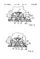
- FIG. 5is a side view of the lower part of the drive unit of FIG. 4 when fitted with an orbital sander shoe;
- FIG. 6is a side view of the lower part of the drive unit of FIG. 4 when fitted with a random orbit sander platen;
- FIG. 7is a side view, partially in section, of the drive unit of a third embodiment of a hand tool according to the present invention, shown without an operating head;
- FIG. 8is a side view of the lower part of the drive unit of FIG. 7 when fitted with an orbital sander shoe, and
- FIG. 9is a side view of the lower part of the drive unit of FIG. 7 when fitted with a random orbit sander platen.
- FIG. 1shows a drive unit (5) including an electric motor (2) located in upper housing (6) and driving shaft (7).
- a fan (8) mounted on shaft (7)is arranged to draw air in from mouth (9) of lower housing (10) and direct it through extractor duct (11) to exhaust outlet (12).
- a nut (13)is used to secure operating heads (see FIGS. 2 and 3) to shaft (14) which is housed in the fan (8) by bearing (15) which is eccentrically located radially in respect to shaft (7).
- Each flexible column (16)has a more flexible angled leg (17) projecting from the column (16) a short distance from the tip (18) so that in the unstressed position the end (19) of the leg (17) projects beyond the tip (18) of the column (16).
- Drive unit (5)can alternatively be fitted with an (oscillating) orbital sander shoe (20), (FIG. 2) or with a random orbit sander platen (21) (FIG. 3).
- shoe (20)is supported by tips (18) of the flexible columns (16) which fit into slotted posts 3 formed on an upper surface 4 of the shoe, is driven by the electric motor (2) (FIG. 1) through shafts (7,14).
- the angled legs (17)in this case are deflected from the flexible columns (16) to lie level with the upper surface (4) of the shoe (20).
- a perforated sandpaper sheet(not shown) may be attached to the outer face (22) of the shoe (20), for example by the use of hook-and-loop fabric such as that sold as VELCRO (RTM) glued to face (22). Holes (23) passing through the shoe (20) facilitate the removal of dust etc, from the sanding face through the shoe (20) to exhaust outlet (12) via the duct (11).
- An extractor hose(not shown) may be attached to the exhaust outlet (12).
- platen (21)is driven by the electric motor (2) (FIG. 1) by means of shafts (7,14).
- a perforated sandpaper sheetmay be attached to the outer face (24) of the platen (21), for example by the use of hook-and-loop fabric glued to the face (24). Holes (25) passing through the platen (21) again facilitate removal of dust etc, through the platen (21) to exhaust outlet (12). In this case, tips (18) of the flexible columns (16) are held away from the platen (21) so that the ends (19) of the angled legs (17) contact the platen (21). In operation, ends (19) of legs (17) drag against the rotating platen (21) to exert a braking effect.
- the inventionthus provides a powered oscillating power tool which can easily be fitted with an orbital sander head or with an efficiently braked random orbit sander head without requiring adjustment to the drive.
- FIGS. 4 to 6 of the accompanying drawingslike components are similarly numbered as in FIGS. 1 to 3.
- the drive unit (5), upper housing (6), drive shaft (7), fan (8), mouth (9), lower housing (10), duct (11), outlet (12), screw (13), shaft (14 and bearing (15)are as described with reference to FIGS. 1 to 4.
- a shroud (42)surrounds the fan (8), within the lower housing (10) and a flange (44) is provided at the lower end of a wall (46) of the shroud (42).
- a plurality of location slot (48)are formed in the flange (44) and are adapted to receive corresponding location pegs (50) of an annular brake ring (52).
- This brake ring (52)is formed of a flexible material, for example rubber, and when attached to the shroud (42) depends from that shroud and projects beyond the lower housing (10).
- Drive (5)can alternatively be fitted with an orbital sander shoe (54), (FIG. 5) or a random orbit sander platen (56), (FIG. 6).
- the shoe (54)is driven by the electric motor through shafts (7,14).
- a slotted groove (58), suitably made from a thermoplastic material,is provided on the upper surface (60) of the shoe (54), and is preferably moulded integrally with the shoe backing plate (62). As the shoe (54) is mounted on the shaft (14), the brake ring (52) engages in the groove (58).
- the shoe (54)may be removed and replaced by a random orbit platen (56).
- the brake ring (52)engages in the groove (58) and restricts the motion of the shoe (54) to a conventional orbital motion.
- the platen ring (64)engages with, and rolls around the internal circumference of the brake ring (52), thus limiting the rotational speed of the platen (56) and significantly reducing the stop time when the power supply to the unit is interrupted.
- FIGS. 7 to 9 of the accompanying drawingslike components are again numbered as in FIGS. 1 to 6.
- spigots bosses (72)are provided on the underside of the floor (74) of the motor housing.
- These spigots (72)are suitably made of a thermoplastic material and are preferably integrally moulded with the floor (74) of the motor housing.
- Drive unit (5)can alternatively be fitted with an orbital sander shoe (76), (FIG. 8) or with a random orbit sander platen (78), (FIG. 9).
- each of the legs (80)engages a corresponding spigot (72).
- the legs (80)are shaped for engagement with the spigots (72) and may be made of any flexible material, eg rubber or a synthetic plastics material, and may be welded, screwed, bonded, integrally moulded with or fastened by any appropriate means to the shoe (76).
- the shoe (76)may be removed and replaced by a random orbit sander platen (78). If it is wished to provide braking for the sander in the random orbit mode, then a separate brake must be provided in a manner known per se.
- each of the legs (80)engages in a corresponding spigot (72) and the motion of the shoe is restricted to a conventional regular orbit.
- the platenis free to rotate in a random orbit.
- the legsare attached to the shoe, and engage in spigots in the drive unit. It is, however, within the scope of the invention for the legs to be attached to the drive unit and engage with spigots on the backing plate of the shoe. With this variation, it is possible for the legs to provide a braking effect in random orbit mode, thus obviating the need for a separate brake component.
- the powered oscillating hand tool according to the inventionis particularly adapted for use with sanding heads such as random orbit sanding platens and orbital sanding shoes, it is of course within the scope of the invention to provide a tool to which further alternative oscillating heads can be attached.
Landscapes
- Engineering & Computer Science (AREA)
- Mechanical Engineering (AREA)
- Finish Polishing, Edge Sharpening, And Grinding By Specific Grinding Devices (AREA)
Abstract
Description
This is a Continuation of application Ser. No. 08/701,568 filed Aug. 22, 1996, now abandoned, which is a continuation of application Ser. No. 08/503,109, filed Jul. 17, 1995, now abandoned.
The present invention relates to a powered oscillating hand tool comprising a drive unit having an electric motor with a drive shaft to which a sander head can be attached. In general, known sanders can be described as either random orbit sanders or orbital sanders.
In random orbit sanders, a circular platen is driven by a drive system which comprises an eccentric bearing so that the platen can spin independently of the motor, and the platen describes a random orbit. Such sanders are in general used for the removal of relatively large quantities of material. Alternatively, the sander may be of the orbital type, with a shaped shoe, the drive system of which comprises an eccentric which is restrained so that the sander shoe cannot spin independently of the motor and it therefore describes a regular orbit. The shoes of such sanders are available in a range of shapes and such sanders are in general used for the removal of relatively small quantities of material, for example for detailed work or for finishing. By choice of a suitably shaped shoe, it is possible to access areas which are inaccessible with a random orbit sander. The fixed eccentric drive system of the orbital sander is cheaper and simpler to manufacture than the eccentric bearing of the random orbit sander.
Known sanders have been either of the random orbit type or the orbital type, which has meant that when the user wished to have the ability to perform both coarse and detailed sanding operations, it has been necessary for him to purchase two separate units, one of each type, or to purchase only one unit and suffer the disadvantages thereof.
It is an object of the present invention to provide a sander in which the above disadvantages are reduced or substantially obviated.
The present invention therefore provides a dual function powered oscillating hand tool comprising
(i) a drive unit having an electric motor and a drive shaft;
(ii) a bearing mounted on the drive shaft and located radially eccentrically relative to the drive shaft;
(iii) a second drive shaft mounted in the eccentric bearing and
(iv) means for mounting a sanding platen or shoe on the second drive shaft characterized in that the sanding head may comprise a sanding platen for random orbit sanding or a sanding shoe for orbital sanding and in that the tool further comprises means selectively engageable to restrict the random orbit of the sanding shoe to a regular orbit.
The invention will now be further described with reference to the accompanying drawings in which
FIG. 1 is a side view, partially in section, of the drive unit of a first embodiment of a hand tool according to the present invention, shown without an operating head;
FIG. 2 is a side view of the lower part of the drive unit of FIG. 1 when fitted with an orbital sander shoe;
FIG. 3 is a side view of the lower part of the drive unit of FIG. 1 when fitted with a random orbit sander platen;
FIG. 4 is a side view, partially in section of the drive unit of a second embodiment of a hand tool according to the present invention, shown without an operating head;
FIG. 5 is a side view of the lower part of the drive unit of FIG. 4 when fitted with an orbital sander shoe;
FIG. 6 is a side view of the lower part of the drive unit of FIG. 4 when fitted with a random orbit sander platen;
FIG. 7 is a side view, partially in section, of the drive unit of a third embodiment of a hand tool according to the present invention, shown without an operating head;
FIG. 8 is a side view of the lower part of the drive unit of FIG. 7 when fitted with an orbital sander shoe, and
FIG. 9 is a side view of the lower part of the drive unit of FIG. 7 when fitted with a random orbit sander platen.
FIG. 1 shows a drive unit (5) including an electric motor (2) located in upper housing (6) and driving shaft (7). A fan (8) mounted on shaft (7) is arranged to draw air in from mouth (9) of lower housing (10) and direct it through extractor duct (11) to exhaust outlet (12). A nut (13) is used to secure operating heads (see FIGS. 2 and 3) to shaft (14) which is housed in the fan (8) by bearing (15) which is eccentrically located radially in respect to shaft (7).
Two pairs of hollow, tapering, flexible columns (16) made of rubber are arranged around the mouth (9) of the lower housing (10). Each flexible column (16) has a more flexible angled leg (17) projecting from the column (16) a short distance from the tip (18) so that in the unstressed position the end (19) of the leg (17) projects beyond the tip (18) of the column (16).
Drive unit (5) can alternatively be fitted with an (oscillating) orbital sander shoe (20), (FIG. 2) or with a random orbit sander platen (21) (FIG. 3).
As seen in FIG. 2, shoe (20) is supported by tips (18) of the flexible columns (16) which fit into slottedposts 3 formed on anupper surface 4 of the shoe, is driven by the electric motor (2) (FIG. 1) through shafts (7,14). The angled legs (17) in this case are deflected from the flexible columns (16) to lie level with the upper surface (4) of the shoe (20). A perforated sandpaper sheet (not shown) may be attached to the outer face (22) of the shoe (20), for example by the use of hook-and-loop fabric such as that sold as VELCRO (RTM) glued to face (22). Holes (23) passing through the shoe (20) facilitate the removal of dust etc, from the sanding face through the shoe (20) to exhaust outlet (12) via the duct (11). An extractor hose (not shown) may be attached to the exhaust outlet (12).
As seen in FIG. 3, platen (21) is driven by the electric motor (2) (FIG. 1) by means of shafts (7,14).
Again, a perforated sandpaper sheet (not shown) may be attached to the outer face (24) of the platen (21), for example by the use of hook-and-loop fabric glued to the face (24). Holes (25) passing through the platen (21) again facilitate removal of dust etc, through the platen (21) to exhaust outlet (12). In this case, tips (18) of the flexible columns (16) are held away from the platen (21) so that the ends (19) of the angled legs (17) contact the platen (21). In operation, ends (19) of legs (17) drag against the rotating platen (21) to exert a braking effect.
The invention thus provides a powered oscillating power tool which can easily be fitted with an orbital sander head or with an efficiently braked random orbit sander head without requiring adjustment to the drive.
In a second embodiment shown in FIGS. 4 to 6 of the accompanying drawings, like components are similarly numbered as in FIGS. 1 to 3.
As can be seen from FIG. 4, the drive unit (5), upper housing (6), drive shaft (7), fan (8), mouth (9), lower housing (10), duct (11), outlet (12), screw (13), shaft (14 and bearing (15) are as described with reference to FIGS. 1 to 4.
A shroud (42) surrounds the fan (8), within the lower housing (10) and a flange (44) is provided at the lower end of a wall (46) of the shroud (42). A plurality of location slot (48) are formed in the flange (44) and are adapted to receive corresponding location pegs (50) of an annular brake ring (52). This brake ring (52) is formed of a flexible material, for example rubber, and when attached to the shroud (42) depends from that shroud and projects beyond the lower housing (10).
Drive (5) can alternatively be fitted with an orbital sander shoe (54), (FIG. 5) or a random orbit sander platen (56), (FIG. 6).
As can be seen in FIG. 5, the shoe (54) is driven by the electric motor through shafts (7,14). A slotted groove (58), suitably made from a thermoplastic material, is provided on the upper surface (60) of the shoe (54), and is preferably moulded integrally with the shoe backing plate (62). As the shoe (54) is mounted on the shaft (14), the brake ring (52) engages in the groove (58).
As can be seen from FIG. 6, the shoe (54) may be removed and replaced by a random orbit platen (56). A raised ring (64), suitably made from a thermoplastic material and moulded integrally with the platen backing plate (66), is provided in the upper surface (68) of the platen (56). As the platen (56) is mounted on the shaft (14), the raised ring (64) engages in the brake ring (52).
In operation, in the orbital mode the brake ring (52) engages in the groove (58) and restricts the motion of the shoe (54) to a conventional orbital motion. In the random orbit mode, the platen ring (64) engages with, and rolls around the internal circumference of the brake ring (52), thus limiting the rotational speed of the platen (56) and significantly reducing the stop time when the power supply to the unit is interrupted.
In a third embodiment shown in FIGS. 7 to 9 of the accompanying drawings, like components are again numbered as in FIGS. 1 to 6.
In this embodiment, as can be seen from FIG. 7, four upstanding spigots bosses (72) are provided on the underside of the floor (74) of the motor housing. These spigots (72) are suitably made of a thermoplastic material and are preferably integrally moulded with the floor (74) of the motor housing.
Drive unit (5) can alternatively be fitted with an orbital sander shoe (76), (FIG. 8) or with a random orbit sander platen (78), (FIG. 9).
As can be seen from FIG. 8, four hollow legs (80) are provided on the backing plate of the shoe (76). As the shoe (76) is mounted on the shaft (14), each of the legs (80) engages a corresponding spigot (72). The legs (80) are shaped for engagement with the spigots (72) and may be made of any flexible material, eg rubber or a synthetic plastics material, and may be welded, screwed, bonded, integrally moulded with or fastened by any appropriate means to the shoe (76).
As can be seen from FIG. 9, the shoe (76) may be removed and replaced by a random orbit sander platen (78). If it is wished to provide braking for the sander in the random orbit mode, then a separate brake must be provided in a manner known per se.
In operation, in the orbital mode, each of the legs (80) engages in a corresponding spigot (72) and the motion of the shoe is restricted to a conventional regular orbit. In the random orbit mode, the platen is free to rotate in a random orbit.
In the embodiment shown in FIGS. 7 to 9, the legs are attached to the shoe, and engage in spigots in the drive unit. It is, however, within the scope of the invention for the legs to be attached to the drive unit and engage with spigots on the backing plate of the shoe. With this variation, it is possible for the legs to provide a braking effect in random orbit mode, thus obviating the need for a separate brake component.
While the powered oscillating hand tool according to the invention is particularly adapted for use with sanding heads such as random orbit sanding platens and orbital sanding shoes, it is of course within the scope of the invention to provide a tool to which further alternative oscillating heads can be attached.
Claims (10)
1. A dual function powered oscillating hand tool comprising:
(i) a drive unit having an electric motor and a drive shaft;
(ii) a bearing mounted on said drive shaft and located radially eccentrically relative to said drive shaft;
(iii) a second drive shaft mounted on the eccentric bearing;
(iv) means for mounting a sanding head on said second drive shaft for random orbit; and
(v) means selectively engageable for restricting said random orbit of said sanding head to a regular orbit, the sanding head being structured as a sanding platen for random orbit and as a sanding shoe for regular orbit.
2. A dual function powered oscillating hand tool according to claim 1 further wherein said means selectively engageable to restrict said random orbit of said sanding shoe to a regular orbit comprises a flexible component and a rigid component, one of which components is mounted on said shoe and the other of which is mounted on said drive unit.
3. A dual function powered oscillating hand tool according to claim 2 further wherein said flexible component comprises a plurality of flexible legs located on said shoe and said rigid component comprises a similar number of rigid location points mounted on said housing and arranged for engagement with said flexible legs, when said shoe is mounted on said second drive shaft.
4. A dual function powered oscillating hand tool according to claim 3 further wherein said flexible legs are hollow, and said rigid location points are bosses which engage in said hollow legs.
5. A dual function powered oscillating hand tool according to claim 1 wherein said tool comprises a brake which is operative in said random orbit mode.
6. A dual function powered oscillating hand tool according to claim 5 wherein said means selectively engageable to restrict said random orbit of said sanding platen to a regular orbit includes a flexible component which is located on said drive unit and is a component of said brake.
7. A dual function powered oscillating hand tool according to claim 2 wherein said flexible component of said means selectively engageable to restrict said random orbit of said sanding shoe to a regular orbit comprises a flexible ring.
8. A dual function powered oscillating hand tool according to claim 7 wherein said flexible ring is a rubber ring.
9. A dual function powered oscillating hand tool according to claim 2 wherein said flexible component of said means selectively engageable to restrict said random orbit of said sanding shoe to a regular orbit comprises a flexible post with a trailing leg.
10. A dual function powered oscillating hand tool according to claim 2 wherein said flexible component of said means selectively engageable to restrict said random orbit of said sanding shoe to a regular orbit comprises a flexible post, trapped between a first captivator located on said housing and a second captivator located on said shoe.
Priority Applications (1)
| Application Number | Priority Date | Filing Date | Title |
|---|---|---|---|
| US08/876,316US6132300A (en) | 1994-07-26 | 1997-06-16 | Dual function oscillating tool |
Applications Claiming Priority (5)
| Application Number | Priority Date | Filing Date | Title |
|---|---|---|---|
| GB9415011 | 1994-07-26 | ||
| GB9415011AGB9415011D0 (en) | 1994-07-26 | 1994-07-26 | Improved oscillating hand tool |
| US50310995A | 1995-07-17 | 1995-07-17 | |
| US70156896A | 1996-08-22 | 1996-08-22 | |
| US08/876,316US6132300A (en) | 1994-07-26 | 1997-06-16 | Dual function oscillating tool |
Related Parent Applications (1)
| Application Number | Title | Priority Date | Filing Date |
|---|---|---|---|
| US70156896AContinuation | 1994-07-26 | 1996-08-22 |
Publications (1)
| Publication Number | Publication Date |
|---|---|
| US6132300Atrue US6132300A (en) | 2000-10-17 |
Family
ID=10758863
Family Applications (1)
| Application Number | Title | Priority Date | Filing Date |
|---|---|---|---|
| US08/876,316Expired - LifetimeUS6132300A (en) | 1994-07-26 | 1997-06-16 | Dual function oscillating tool |
Country Status (9)
| Country | Link |
|---|---|
| US (1) | US6132300A (en) |
| EP (1) | EP0694365B2 (en) |
| JP (1) | JP3623552B2 (en) |
| CN (1) | CN1088001C (en) |
| CA (1) | CA2153430C (en) |
| DE (2) | DE69500754T4 (en) |
| ES (1) | ES2091736T5 (en) |
| GB (1) | GB9415011D0 (en) |
| HK (1) | HK1000765A1 (en) |
Cited By (44)
| Publication number | Priority date | Publication date | Assignee | Title |
|---|---|---|---|---|
| US6264539B1 (en)* | 2000-01-12 | 2001-07-24 | Tony Chen | Mechanism for slowing down idling shoe of an electric polisher |
| EP1277544A3 (en)* | 2001-07-20 | 2004-01-28 | Black & Decker Inc. | Oscillating hand tool |
| EP1277543A3 (en)* | 2001-07-20 | 2004-01-28 | Black & Decker Inc. | Oscillating hand tool |
| US20040038622A1 (en)* | 2001-07-14 | 2004-02-26 | Joerg Dehde | Manual machine-tool comprising a braking means |
| US20040043714A1 (en)* | 2002-06-13 | 2004-03-04 | Zhiyong Yi | Power tool with a clamping device for axially securing a disk shaped tool |
| US20040053568A1 (en)* | 2001-12-07 | 2004-03-18 | Gustav Sieber | Manual orbital sander |
| US6758731B2 (en) | 2001-08-10 | 2004-07-06 | One World Technologies Limited | Orbital sander |
| US20040132392A1 (en)* | 2002-01-08 | 2004-07-08 | Daniel Bohler | Device for the treatment of surfaces |
| US20040167481A1 (en)* | 2003-01-16 | 2004-08-26 | Conair Corporation | Hand-held buffing device |
| US6796888B2 (en)* | 2000-12-07 | 2004-09-28 | C. & E. Fein Gmbh & Co. Kg | Power tool having a receptacle for securing a tool |
| US20050095966A1 (en)* | 2000-12-07 | 2005-05-05 | Michael Jasch | Power tool having a receptacle for securing a tool |
| EP1674202A1 (en)* | 2004-12-23 | 2006-06-28 | Black & Decker, Inc. | Modular Sander-Casing Architecture |
| EP1714739A1 (en)* | 2005-04-19 | 2006-10-25 | Positec Power Tools (Suzhou) Co., Ltd. | Hand guided sanding tool |
| EP1745887A1 (en) | 2005-07-21 | 2007-01-24 | Positec Power Tools (Suzhou) Co., Ltd. | Sanding tool |
| US20070072525A1 (en)* | 2005-09-27 | 2007-03-29 | Ming-Ta Cheng | Polishing machine with a brake device |
| US20080057842A1 (en)* | 2006-09-05 | 2008-03-06 | Dynabrade, Inc. | Locking random orbital dual-action head assembly |
| US20090209182A1 (en)* | 2006-09-05 | 2009-08-20 | Dynabrade, Inc. | Locking random orbital dual-action head assembly |
| CN100577359C (en)* | 2005-07-21 | 2010-01-06 | 苏州宝时得电动工具有限公司 | Multifunctional sander |
| EP2156925A2 (en) | 2008-08-20 | 2010-02-24 | BLACK & DECKER INC. | Sander |
| US20100151775A1 (en)* | 2006-09-05 | 2010-06-17 | Dynabrade, Inc. | Locking random orbital dual-action head assembly with centering |
| CN101633143B (en)* | 2008-07-25 | 2012-10-24 | 苏州宝时得电动工具有限公司 | Hand-held tool and application method thereof |
| US20130288581A1 (en)* | 2010-10-29 | 2013-10-31 | Robert Bosch Gmbh | Portable Machine Tool |
| US20140190716A1 (en)* | 2011-09-12 | 2014-07-10 | Makita Corporation | Electric power tool |
| US8915499B2 (en) | 2010-11-09 | 2014-12-23 | Black & Decker Inc. | Universal accessories for oscillating power tools |
| US8925931B2 (en) | 2010-04-29 | 2015-01-06 | Black & Decker Inc. | Oscillating tool |
| US20150151422A1 (en)* | 2013-11-29 | 2015-06-04 | Black & Decker Inc. | Sander having two-piece fan |
| US9149923B2 (en) | 2010-11-09 | 2015-10-06 | Black & Decker Inc. | Oscillating tools and accessories |
| US9186770B2 (en) | 2010-04-29 | 2015-11-17 | Black & Decker Inc. | Oscillating tool attachment feature |
| US9421682B2 (en) | 2011-07-18 | 2016-08-23 | Black & Decker Inc. | Multi-head power tool with reverse lock-out capability |
| US9555554B2 (en) | 2013-05-06 | 2017-01-31 | Milwaukee Electric Tool Corporation | Oscillating multi-tool system |
| CN106493623A (en)* | 2015-09-04 | 2017-03-15 | 南京德朔实业有限公司 | Polishing class instrument and sander |
| CN106625140A (en)* | 2015-10-29 | 2017-05-10 | 南京德朔实业有限公司 | Sanding machine |
| CN106826487A (en)* | 2017-02-20 | 2017-06-13 | 吴涛 | A kind of machinery part surface processing unit |
| CN107745312A (en)* | 2016-06-28 | 2018-03-02 | 苏州宝时得电动工具有限公司 | The assembly and disassembly methods of sander and its operating method and working plate |
| CN107756202A (en)* | 2016-08-15 | 2018-03-06 | 苏州宝时得电动工具有限公司 | Sander |
| USD814900S1 (en) | 2017-01-16 | 2018-04-10 | Black & Decker Inc. | Blade for oscillating power tools |
| US9956677B2 (en) | 2013-05-08 | 2018-05-01 | Black & Decker Inc. | Power tool with interchangeable power heads |
| CN108067985A (en)* | 2016-11-08 | 2018-05-25 | 苏州宝时得电动工具有限公司 | Sander |
| US10076819B2 (en) | 2014-05-15 | 2018-09-18 | Barry ULRICH | Sandpaper sheet for use with tools configured for dust extraction |
| USD832666S1 (en) | 2012-07-16 | 2018-11-06 | Black & Decker Inc. | Oscillating saw blade |
| US10265778B2 (en) | 2017-01-16 | 2019-04-23 | Black & Decker Inc. | Accessories for oscillating power tools |
| US10632589B2 (en) | 2016-08-29 | 2020-04-28 | Black & Decker Inc. | Power tool |
| US20220016738A1 (en)* | 2020-07-15 | 2022-01-20 | Makita Corporation | Portable power tool |
| US11529711B2 (en) | 2016-06-28 | 2022-12-20 | Positec Power Tools (Suzhou) Co., Ltd. | Sanding machine, operating method thereof and working baseplate disassembly-assembly method |
Families Citing this family (17)
| Publication number | Priority date | Publication date | Assignee | Title |
|---|---|---|---|---|
| DE19852137A1 (en)* | 1998-11-12 | 2000-05-18 | Bosch Gmbh Robert | Motorized hand grinder |
| DE29900612U1 (en)* | 1999-01-15 | 1999-03-18 | Chung, Lee-Hsin-Chih, Chung-Li, Taoyuan | Delay device for a grinding machine |
| DE19963831B4 (en)* | 1999-12-30 | 2006-04-06 | Robert Bosch Gmbh | Eccentric disc grinder with a housing |
| DE102004035520A1 (en)* | 2004-07-22 | 2006-02-09 | Robert Bosch Gmbh | Hand tool, in particular hand-guided grinding machine |
| NL1030176C2 (en)* | 2005-10-12 | 2007-04-17 | Bosch Gmbh Robert | Hand tools with improved drive. |
| JP4819623B2 (en) | 2006-08-31 | 2011-11-24 | 株式会社マキタ | Sanda |
| CN101172331A (en)* | 2006-11-02 | 2008-05-07 | 苏州宝时得电动工具有限公司 | Multifunctional sanding grinder |
| CN201061862Y (en)* | 2007-06-25 | 2008-05-21 | 南京德朔实业有限公司 | Electric grinding tool |
| US7736216B2 (en) | 2008-08-20 | 2010-06-15 | Black & Decker Inc. | Sander having removable platen |
| CZ2013107A3 (en)* | 2013-02-15 | 2014-08-27 | Petr Froněk | Grinding machine for grinding curved surfaces |
| CN105983891B (en)* | 2015-02-16 | 2018-04-20 | 苏州宝时得电动工具有限公司 | Multifunction sander |
| CN107791130B (en)* | 2016-09-07 | 2023-12-08 | 苏州宝时得电动工具有限公司 | Multifunctional sander |
| EP3646987B1 (en) | 2018-10-29 | 2023-06-14 | Guido Valentini | Hand-held and hand-guided random orbital polishing or sanding power tool |
| EP3693132B1 (en) | 2019-02-08 | 2023-09-06 | Guido Valentini | Hand-held and hand-guided random orbital polishing or sanding power tool |
| EP3736084B1 (en)* | 2019-05-07 | 2021-03-10 | Guido Valentini | Hand-held power tool for sanding or polishing a workpiece |
| EP4450224A1 (en)* | 2023-04-17 | 2024-10-23 | X'Pole Precision Tools Inc. | Random orbital sanding tool |
| EP4474105A1 (en) | 2023-06-07 | 2024-12-11 | X'Pole Precision Tools Inc. | Random orbital sanding tool |
Citations (29)
| Publication number | Priority date | Publication date | Assignee | Title |
|---|---|---|---|---|
| US3747280A (en)* | 1970-08-08 | 1973-07-24 | Bosch Gmbh Robert | Portable power tool with orbital work-engaging means |
| US3862520A (en)* | 1974-02-14 | 1975-01-28 | Singer Co | Support assembly for a portable surface-treating machine |
| US3862521A (en)* | 1972-04-14 | 1975-01-28 | Teda Lab I Eskilstuna Ab | Abrasive grit exhaust system in grinding machines |
| US3874125A (en)* | 1973-03-31 | 1975-04-01 | Bosch Gmbh Robert | Convertible pad sander |
| US3932966A (en)* | 1974-03-26 | 1976-01-20 | Bill Peter Philip Nederman | Abrasive disc |
| US4322921A (en)* | 1979-09-25 | 1982-04-06 | Peter Maier | Eccentric plate grinder |
| US4397120A (en)* | 1981-09-01 | 1983-08-09 | Black & Decker Inc. | Suspension system for an abrading tool |
| US4414781A (en)* | 1981-09-01 | 1983-11-15 | Black & Decker Inc. | Turbine sander |
| US4414782A (en)* | 1981-09-01 | 1983-11-15 | Black & Decker Inc. | Direct drive system for a turbine sander |
| US4468895A (en)* | 1983-03-28 | 1984-09-04 | Signorelli Gary J | Surface grinder attachment |
| US4625462A (en)* | 1984-08-29 | 1986-12-02 | Makita Electric Works, Ltd. | Cordless electric finishing sander |
| US4660329A (en)* | 1980-10-20 | 1987-04-28 | Hutchins Manufacturing Company | Powered abrading tool |
| US4708041A (en)* | 1986-08-26 | 1987-11-24 | Granger Robert A | Lathe mounting apparatus |
| US4729194A (en)* | 1985-05-25 | 1988-03-08 | Festo Kg | Balanced orbital sander/grinder |
| US4744177A (en)* | 1984-09-08 | 1988-05-17 | Licentia Patent-Verwaltungs-Gmbh | Vibratory abrader |
| US4754575A (en)* | 1986-05-10 | 1988-07-05 | Robert Bosch Gmbh | Eccentric grinder with means for changing a grinding motion |
| DE3805926A1 (en)* | 1988-02-25 | 1989-09-07 | Bosch Gmbh Robert | Hand-held unit with oscillating tool movement |
| US5018314A (en)* | 1989-06-08 | 1991-05-28 | Makita Electric Works, Ltd. | Sander |
| US5056268A (en)* | 1989-10-23 | 1991-10-15 | Werkzeug Gmbh | Accessory device for angle grinder |
| DE4118392A1 (en)* | 1991-06-05 | 1992-12-10 | Bosch Gmbh Robert | Eccentric grinder |
| US5261190A (en)* | 1989-03-02 | 1993-11-16 | Robert Bosch Gmbh | Eccentric grinder |
| US5317838A (en)* | 1991-11-06 | 1994-06-07 | Black & Decker Inc. | Sanding apparatus |
| US5384984A (en)* | 1993-01-22 | 1995-01-31 | Porter-Cable Corporation | Random orbit sander with brake |
| US5392568A (en)* | 1993-12-22 | 1995-02-28 | Black & Decker Inc. | Random orbit sander having braking member |
| US5398454A (en)* | 1992-07-14 | 1995-03-21 | Robert Bosch Gmbh | Surface grinding machine |
| US5398457A (en)* | 1992-12-11 | 1995-03-21 | Updegrave; Scott A. | Edge and corner sanding attachment |
| US5441450A (en)* | 1993-05-05 | 1995-08-15 | C.&E. Fein Gmbh & Co. | Power tool having means to switch from oscillatory movement to rotary movement |
| US5470272A (en)* | 1994-02-03 | 1995-11-28 | Ryobi Motor Products Corp. | Removable working tool assembly |
| US5679066A (en)* | 1992-07-10 | 1997-10-21 | Robert Bosch Gmbh | Eccentric disk grinder with a grinding disk brake |
Family Cites Families (2)
| Publication number | Priority date | Publication date | Assignee | Title |
|---|---|---|---|---|
| DE3742531A1 (en)* | 1987-12-16 | 1989-06-29 | Festo Kg | Eccentric disc grinder |
| DE4039480C2 (en)* | 1990-12-11 | 1994-12-01 | Fraunhofer Ges Forschung | Device for disassembling or loosening connections |
- 1994
- 1994-07-26GBGB9415011Apatent/GB9415011D0/enactivePending
- 1995
- 1995-07-04DEDE69500754Tpatent/DE69500754T4/ennot_activeExpired - Lifetime
- 1995-07-04DEDE69500754Apatent/DE69500754D1/ennot_activeExpired - Lifetime
- 1995-07-04EPEP95304671Apatent/EP0694365B2/ennot_activeExpired - Lifetime
- 1995-07-04ESES95304671Tpatent/ES2091736T5/ennot_activeExpired - Lifetime
- 1995-07-07CACA002153430Apatent/CA2153430C/ennot_activeExpired - Fee Related
- 1995-07-24JPJP18694095Apatent/JP3623552B2/ennot_activeExpired - Fee Related
- 1995-07-26CNCN95115820Apatent/CN1088001C/ennot_activeExpired - Lifetime
- 1997
- 1997-06-16USUS08/876,316patent/US6132300A/ennot_activeExpired - Lifetime
- 1997-12-09HKHK97102372Apatent/HK1000765A1/enunknown
Patent Citations (29)
| Publication number | Priority date | Publication date | Assignee | Title |
|---|---|---|---|---|
| US3747280A (en)* | 1970-08-08 | 1973-07-24 | Bosch Gmbh Robert | Portable power tool with orbital work-engaging means |
| US3862521A (en)* | 1972-04-14 | 1975-01-28 | Teda Lab I Eskilstuna Ab | Abrasive grit exhaust system in grinding machines |
| US3874125A (en)* | 1973-03-31 | 1975-04-01 | Bosch Gmbh Robert | Convertible pad sander |
| US3862520A (en)* | 1974-02-14 | 1975-01-28 | Singer Co | Support assembly for a portable surface-treating machine |
| US3932966A (en)* | 1974-03-26 | 1976-01-20 | Bill Peter Philip Nederman | Abrasive disc |
| US4322921A (en)* | 1979-09-25 | 1982-04-06 | Peter Maier | Eccentric plate grinder |
| US4660329A (en)* | 1980-10-20 | 1987-04-28 | Hutchins Manufacturing Company | Powered abrading tool |
| US4397120A (en)* | 1981-09-01 | 1983-08-09 | Black & Decker Inc. | Suspension system for an abrading tool |
| US4414781A (en)* | 1981-09-01 | 1983-11-15 | Black & Decker Inc. | Turbine sander |
| US4414782A (en)* | 1981-09-01 | 1983-11-15 | Black & Decker Inc. | Direct drive system for a turbine sander |
| US4468895A (en)* | 1983-03-28 | 1984-09-04 | Signorelli Gary J | Surface grinder attachment |
| US4625462A (en)* | 1984-08-29 | 1986-12-02 | Makita Electric Works, Ltd. | Cordless electric finishing sander |
| US4744177A (en)* | 1984-09-08 | 1988-05-17 | Licentia Patent-Verwaltungs-Gmbh | Vibratory abrader |
| US4729194A (en)* | 1985-05-25 | 1988-03-08 | Festo Kg | Balanced orbital sander/grinder |
| US4754575A (en)* | 1986-05-10 | 1988-07-05 | Robert Bosch Gmbh | Eccentric grinder with means for changing a grinding motion |
| US4708041A (en)* | 1986-08-26 | 1987-11-24 | Granger Robert A | Lathe mounting apparatus |
| DE3805926A1 (en)* | 1988-02-25 | 1989-09-07 | Bosch Gmbh Robert | Hand-held unit with oscillating tool movement |
| US5261190A (en)* | 1989-03-02 | 1993-11-16 | Robert Bosch Gmbh | Eccentric grinder |
| US5018314A (en)* | 1989-06-08 | 1991-05-28 | Makita Electric Works, Ltd. | Sander |
| US5056268A (en)* | 1989-10-23 | 1991-10-15 | Werkzeug Gmbh | Accessory device for angle grinder |
| DE4118392A1 (en)* | 1991-06-05 | 1992-12-10 | Bosch Gmbh Robert | Eccentric grinder |
| US5317838A (en)* | 1991-11-06 | 1994-06-07 | Black & Decker Inc. | Sanding apparatus |
| US5679066A (en)* | 1992-07-10 | 1997-10-21 | Robert Bosch Gmbh | Eccentric disk grinder with a grinding disk brake |
| US5398454A (en)* | 1992-07-14 | 1995-03-21 | Robert Bosch Gmbh | Surface grinding machine |
| US5398457A (en)* | 1992-12-11 | 1995-03-21 | Updegrave; Scott A. | Edge and corner sanding attachment |
| US5384984A (en)* | 1993-01-22 | 1995-01-31 | Porter-Cable Corporation | Random orbit sander with brake |
| US5441450A (en)* | 1993-05-05 | 1995-08-15 | C.&E. Fein Gmbh & Co. | Power tool having means to switch from oscillatory movement to rotary movement |
| US5392568A (en)* | 1993-12-22 | 1995-02-28 | Black & Decker Inc. | Random orbit sander having braking member |
| US5470272A (en)* | 1994-02-03 | 1995-11-28 | Ryobi Motor Products Corp. | Removable working tool assembly |
Cited By (103)
| Publication number | Priority date | Publication date | Assignee | Title |
|---|---|---|---|---|
| US6264539B1 (en)* | 2000-01-12 | 2001-07-24 | Tony Chen | Mechanism for slowing down idling shoe of an electric polisher |
| US20050095966A1 (en)* | 2000-12-07 | 2005-05-05 | Michael Jasch | Power tool having a receptacle for securing a tool |
| US6796888B2 (en)* | 2000-12-07 | 2004-09-28 | C. & E. Fein Gmbh & Co. Kg | Power tool having a receptacle for securing a tool |
| US6945862B2 (en)* | 2000-12-07 | 2005-09-20 | C. & E. Fein Gmbh | Power tool having a receptacle for securing a tool |
| US6890247B2 (en)* | 2001-07-14 | 2005-05-10 | Robert Bosch Gmbh | Manual machine-tool comprising a braking means |
| US20040038622A1 (en)* | 2001-07-14 | 2004-02-26 | Joerg Dehde | Manual machine-tool comprising a braking means |
| US6780094B2 (en)* | 2001-07-20 | 2004-08-24 | Black & Decker Inc. | Oscillating hand tool |
| US6875095B2 (en)* | 2001-07-20 | 2005-04-05 | Black & Decker Inc. | Oscillating hand tool |
| EP1277543A3 (en)* | 2001-07-20 | 2004-01-28 | Black & Decker Inc. | Oscillating hand tool |
| EP1277544A3 (en)* | 2001-07-20 | 2004-01-28 | Black & Decker Inc. | Oscillating hand tool |
| US7270598B2 (en) | 2001-08-10 | 2007-09-18 | Eastway Fair Company Ltd. | Orbital sander |
| US6758731B2 (en) | 2001-08-10 | 2004-07-06 | One World Technologies Limited | Orbital sander |
| US20050003748A1 (en)* | 2001-08-10 | 2005-01-06 | One World Technologies, Limited | Orbital sander |
| US7052383B2 (en)* | 2001-12-07 | 2006-05-30 | Robert Bosch Gmbh | Manual orbital sander |
| US20040053568A1 (en)* | 2001-12-07 | 2004-03-18 | Gustav Sieber | Manual orbital sander |
| US6848984B2 (en)* | 2002-01-08 | 2005-02-01 | Gunther Bohler Gmbh | Device for the treatment of surfaces |
| US20040132392A1 (en)* | 2002-01-08 | 2004-07-08 | Daniel Bohler | Device for the treatment of surfaces |
| US6929538B2 (en)* | 2002-06-13 | 2005-08-16 | Positec Power Tools (Suzhou) Co., Ltd. | Power tool with a clamping device for axially securing a disk shaped tool |
| US20040043714A1 (en)* | 2002-06-13 | 2004-03-04 | Zhiyong Yi | Power tool with a clamping device for axially securing a disk shaped tool |
| US20040167481A1 (en)* | 2003-01-16 | 2004-08-26 | Conair Corporation | Hand-held buffing device |
| EP1674202A1 (en)* | 2004-12-23 | 2006-06-28 | Black & Decker, Inc. | Modular Sander-Casing Architecture |
| US20060141915A1 (en)* | 2004-12-23 | 2006-06-29 | Walstrum Michael J | Modular sander-casing architecture |
| CN1792568B (en)* | 2004-12-23 | 2012-04-25 | 布莱克和戴克公司 | Modular sander-casing architecture |
| US7198559B2 (en) | 2004-12-23 | 2007-04-03 | Black & Decker, Inc. | Modular sander-casing architecture |
| EP1714739A1 (en)* | 2005-04-19 | 2006-10-25 | Positec Power Tools (Suzhou) Co., Ltd. | Hand guided sanding tool |
| EP1745887A1 (en) | 2005-07-21 | 2007-01-24 | Positec Power Tools (Suzhou) Co., Ltd. | Sanding tool |
| CN100577359C (en)* | 2005-07-21 | 2010-01-06 | 苏州宝时得电动工具有限公司 | Multifunctional sander |
| US20070072525A1 (en)* | 2005-09-27 | 2007-03-29 | Ming-Ta Cheng | Polishing machine with a brake device |
| US7311587B2 (en)* | 2005-09-27 | 2007-12-25 | Ming-Ta Cheng | Polishing machine with a brake device |
| US20100151775A1 (en)* | 2006-09-05 | 2010-06-17 | Dynabrade, Inc. | Locking random orbital dual-action head assembly with centering |
| US20080057842A1 (en)* | 2006-09-05 | 2008-03-06 | Dynabrade, Inc. | Locking random orbital dual-action head assembly |
| US20090209182A1 (en)* | 2006-09-05 | 2009-08-20 | Dynabrade, Inc. | Locking random orbital dual-action head assembly |
| US7713110B2 (en) | 2006-09-05 | 2010-05-11 | Dynabrade, Inc. | Locking random orbital dual-action head assembly |
| WO2008030401A3 (en)* | 2006-09-05 | 2008-08-14 | Dynabrade | Locking random orbital dual-action head assembly |
| CN101633143B (en)* | 2008-07-25 | 2012-10-24 | 苏州宝时得电动工具有限公司 | Hand-held tool and application method thereof |
| US8172642B2 (en)* | 2008-08-20 | 2012-05-08 | Black & Decker Inc. | Multi-sander |
| US20100048101A1 (en)* | 2008-08-20 | 2010-02-25 | King Wade C | Multi-sander |
| EP2156925A2 (en) | 2008-08-20 | 2010-02-24 | BLACK & DECKER INC. | Sander |
| US8398457B2 (en) | 2008-08-20 | 2013-03-19 | Black & Decker Inc. | Multi-sander |
| US10906155B2 (en) | 2008-08-20 | 2021-02-02 | Black & Decker Inc. | Power tool with interchangeable tool head |
| US8613644B2 (en) | 2008-08-20 | 2013-12-24 | Black & Decker Inc. | Multi-sander |
| US9724799B2 (en) | 2008-08-20 | 2017-08-08 | Black & Decker Inc. | Power tool with interchangeable tool head |
| US8821220B2 (en) | 2008-08-20 | 2014-09-02 | Black & Decker Inc. | Power tool with interchangeable tool head |
| EP3050672A1 (en) | 2008-08-20 | 2016-08-03 | Black & Decker Inc. | Sander |
| US9242361B2 (en) | 2010-04-29 | 2016-01-26 | Black & Decker Inc. | Universal accessories for oscillating power tools |
| US8925931B2 (en) | 2010-04-29 | 2015-01-06 | Black & Decker Inc. | Oscillating tool |
| US9073195B2 (en) | 2010-04-29 | 2015-07-07 | Black & Decker Inc. | Universal accessory for oscillating power tool |
| US10040186B2 (en) | 2010-04-29 | 2018-08-07 | Black & Decker Inc. | Universal accessories for oscillating power tools |
| US11498180B2 (en) | 2010-04-29 | 2022-11-15 | Black & Decker Inc. | Oscillating tool |
| US11045919B2 (en) | 2010-04-29 | 2021-06-29 | Black & Decker Inc. | Power tool |
| US9186770B2 (en) | 2010-04-29 | 2015-11-17 | Black & Decker Inc. | Oscillating tool attachment feature |
| US10207385B2 (en) | 2010-04-29 | 2019-02-19 | Black & Decker Inc. | Accessories for oscillating power tools |
| US11097396B2 (en) | 2010-04-29 | 2021-08-24 | Black & Decker Inc. | Accessories for oscillating power tools |
| US10124461B2 (en) | 2010-04-29 | 2018-11-13 | Black & Decker Inc. | Oscillating tool |
| US9539647B2 (en) | 2010-04-29 | 2017-01-10 | Black & Decker Inc. | Oscillating tool |
| US20130288581A1 (en)* | 2010-10-29 | 2013-10-31 | Robert Bosch Gmbh | Portable Machine Tool |
| US9079290B2 (en)* | 2010-10-29 | 2015-07-14 | Robert Bosch Gmbh | Portable machine tool |
| US8915499B2 (en) | 2010-11-09 | 2014-12-23 | Black & Decker Inc. | Universal accessories for oscillating power tools |
| US9149923B2 (en) | 2010-11-09 | 2015-10-06 | Black & Decker Inc. | Oscillating tools and accessories |
| US9421682B2 (en) | 2011-07-18 | 2016-08-23 | Black & Decker Inc. | Multi-head power tool with reverse lock-out capability |
| US20140190716A1 (en)* | 2011-09-12 | 2014-07-10 | Makita Corporation | Electric power tool |
| USD884444S1 (en) | 2012-07-16 | 2020-05-19 | Black & Decker Inc. | Oscillating saw blade |
| USD873099S1 (en) | 2012-07-16 | 2020-01-21 | Black & Decker Inc. | Oscillating saw blade |
| USD856766S1 (en) | 2012-07-16 | 2019-08-20 | Black & Decker Inc. | Oscillating saw blade |
| US10245716B2 (en) | 2012-07-16 | 2019-04-02 | Black & Decker Inc. | Universal accessories for oscillating power tools |
| USD832666S1 (en) | 2012-07-16 | 2018-11-06 | Black & Decker Inc. | Oscillating saw blade |
| US10792801B2 (en) | 2012-07-16 | 2020-10-06 | Black & Decker Inc. | Oscillating power tools and accessories |
| US11235452B2 (en) | 2012-07-16 | 2022-02-01 | Black & Decker Inc. | Accessories for oscillating power tools |
| US10940605B2 (en) | 2013-05-06 | 2021-03-09 | Milwaukee Electric Tool Corporation | Oscillating multi-tool system |
| US10137592B2 (en) | 2013-05-06 | 2018-11-27 | Milwaukee Electric Tool Corporation | Oscillating multi-tool system |
| US12179378B2 (en) | 2013-05-06 | 2024-12-31 | Milwaukee Electric Tool Corporation | Oscillating multi-tool system |
| US11724413B2 (en) | 2013-05-06 | 2023-08-15 | Milwaukee Electric Tool Corporation | Oscillating multi-tool system |
| US9555554B2 (en) | 2013-05-06 | 2017-01-31 | Milwaukee Electric Tool Corporation | Oscillating multi-tool system |
| US10661428B2 (en) | 2013-05-08 | 2020-05-26 | Black & Decker Inc. | Power tool with interchangeable tool heads |
| US9956677B2 (en) | 2013-05-08 | 2018-05-01 | Black & Decker Inc. | Power tool with interchangeable power heads |
| US9102048B2 (en)* | 2013-11-29 | 2015-08-11 | Black & Decker Inc. | Sander having two-piece fan |
| US9545712B2 (en) | 2013-11-29 | 2017-01-17 | Black & Dekcer Inc. | Sander having two-piece fan |
| US20150151422A1 (en)* | 2013-11-29 | 2015-06-04 | Black & Decker Inc. | Sander having two-piece fan |
| US10076819B2 (en) | 2014-05-15 | 2018-09-18 | Barry ULRICH | Sandpaper sheet for use with tools configured for dust extraction |
| CN106493623B (en)* | 2015-09-04 | 2019-08-06 | 南京德朔实业有限公司 | Polishing class tool and sander |
| CN106493623A (en)* | 2015-09-04 | 2017-03-15 | 南京德朔实业有限公司 | Polishing class instrument and sander |
| CN106625140A (en)* | 2015-10-29 | 2017-05-10 | 南京德朔实业有限公司 | Sanding machine |
| CN107745312A (en)* | 2016-06-28 | 2018-03-02 | 苏州宝时得电动工具有限公司 | The assembly and disassembly methods of sander and its operating method and working plate |
| CN107745312B (en)* | 2016-06-28 | 2020-08-14 | 苏州宝时得电动工具有限公司 | Sander, operation method thereof and disassembly and assembly method of working bottom plate |
| US11529711B2 (en) | 2016-06-28 | 2022-12-20 | Positec Power Tools (Suzhou) Co., Ltd. | Sanding machine, operating method thereof and working baseplate disassembly-assembly method |
| CN107756202B (en)* | 2016-08-15 | 2023-12-08 | 苏州宝时得电动工具有限公司 | Sanding machine |
| CN107756202A (en)* | 2016-08-15 | 2018-03-06 | 苏州宝时得电动工具有限公司 | Sander |
| US11478892B2 (en) | 2016-08-29 | 2022-10-25 | Black & Decker Inc. | Power tool |
| US11858085B2 (en) | 2016-08-29 | 2024-01-02 | Black & Decker Inc. | Power tool |
| US11958157B2 (en) | 2016-08-29 | 2024-04-16 | Black & Decker Inc. | Power tool |
| US10632589B2 (en) | 2016-08-29 | 2020-04-28 | Black & Decker Inc. | Power tool |
| CN108067985A (en)* | 2016-11-08 | 2018-05-25 | 苏州宝时得电动工具有限公司 | Sander |
| CN108067985B (en)* | 2016-11-08 | 2023-11-07 | 苏州宝时得电动工具有限公司 | Sanding machine |
| USD814900S1 (en) | 2017-01-16 | 2018-04-10 | Black & Decker Inc. | Blade for oscillating power tools |
| US10265778B2 (en) | 2017-01-16 | 2019-04-23 | Black & Decker Inc. | Accessories for oscillating power tools |
| US12070803B2 (en) | 2017-01-16 | 2024-08-27 | Black & Decker Inc. | Accessories for oscillating power tools |
| USD871185S1 (en) | 2017-01-16 | 2019-12-31 | Black & Decker Inc. | Blade for oscillating power tools |
| US10702927B2 (en) | 2017-01-16 | 2020-07-07 | Black & Decker Inc. | Accessories for oscillating power tools |
| USD924030S1 (en) | 2017-01-16 | 2021-07-06 | Black & Decker Inc. | Blade for oscillating power tools |
| CN106826487A (en)* | 2017-02-20 | 2017-06-13 | 吴涛 | A kind of machinery part surface processing unit |
| CN106826487B (en)* | 2017-02-20 | 2019-01-01 | 湖北京峻汽车零部件有限公司 | A kind of machinery part surface processing unit |
| US11872668B2 (en)* | 2020-07-15 | 2024-01-16 | Makita Corporation | Portable power tool |
| US20220016738A1 (en)* | 2020-07-15 | 2022-01-20 | Makita Corporation | Portable power tool |
Also Published As
| Publication number | Publication date |
|---|---|
| ES2091736T1 (en) | 1996-11-16 |
| DE69500754D1 (en) | 1997-10-30 |
| AU2714895A (en) | 1996-02-08 |
| CA2153430C (en) | 2005-09-06 |
| DE69500754T2 (en) | 1998-01-15 |
| JPH0852648A (en) | 1996-02-27 |
| EP0694365A1 (en) | 1996-01-31 |
| HK1000765A1 (en) | 1998-04-24 |
| ES2091736T3 (en) | 1997-11-01 |
| JP3623552B2 (en) | 2005-02-23 |
| DE69500754T4 (en) | 2001-08-02 |
| EP0694365B1 (en) | 1997-09-24 |
| CN1133219A (en) | 1996-10-16 |
| ES2091736T5 (en) | 2001-01-01 |
| CN1088001C (en) | 2002-07-24 |
| GB9415011D0 (en) | 1994-09-14 |
| CA2153430A1 (en) | 1996-01-27 |
| EP0694365B2 (en) | 2000-11-15 |
| AU686395B2 (en) | 1998-02-05 |
| DE69500754T3 (en) | 2001-02-22 |
Similar Documents
| Publication | Publication Date | Title |
|---|---|---|
| US6132300A (en) | Dual function oscillating tool | |
| HK1000765B (en) | Improved oscillating hand tool | |
| US6179696B1 (en) | Powered oscillating hand tool | |
| US6780094B2 (en) | Oscillating hand tool | |
| CA1215841A (en) | Wet surface treating device and element therefor | |
| US5885146A (en) | Oscillating hand tool | |
| US5807169A (en) | Oscillating hand tool | |
| EP1277543B1 (en) | Oscillating hand tool | |
| JP4061053B2 (en) | Electric sander | |
| US4739534A (en) | High speed floor buffing pad and holder | |
| JPS6359825B2 (en) | ||
| CN2249147Y (en) | Disc-type sand grinding device | |
| US4701970A (en) | High speed floor buffing machine and floor buffing pad | |
| EP0719616B1 (en) | Improved oscillating hand tool | |
| US5181291A (en) | Pad support assembly for floor polishing machine | |
| CA2249127A1 (en) | Assembly for a head of a surface maintenance machine and machine comprising such | |
| JPH0239860U (en) | ||
| JPH0752053A (en) | Buff wheel for wet type polishing |
Legal Events
| Date | Code | Title | Description |
|---|---|---|---|
| STCF | Information on status: patent grant | Free format text:PATENTED CASE | |
| FPAY | Fee payment | Year of fee payment:4 | |
| FPAY | Fee payment | Year of fee payment:8 | |
| FPAY | Fee payment | Year of fee payment:12 |