US6130886A - Coexisting communication systems - Google Patents
Coexisting communication systemsDownload PDFInfo
- Publication number
- US6130886A US6130886AUS08/874,213US87421397AUS6130886AUS 6130886 AUS6130886 AUS 6130886AUS 87421397 AUS87421397 AUS 87421397AUS 6130886 AUS6130886 AUS 6130886A
- Authority
- US
- United States
- Prior art keywords
- time
- base station
- protocol
- user
- time slots
- Prior art date
- Legal status (The legal status is an assumption and is not a legal conclusion. Google has not performed a legal analysis and makes no representation as to the accuracy of the status listed.)
- Expired - Lifetime
Links
- 238000004891communicationMethods0.000titleclaimsabstractdescription171
- 239000002131composite materialSubstances0.000claimsabstractdescription114
- 238000001228spectrumMethods0.000abstractdescription46
- 238000000034methodMethods0.000abstractdescription24
- 230000007480spreadingEffects0.000abstractdescription5
- 238000010586diagramMethods0.000description50
- 230000005540biological transmissionEffects0.000description42
- 230000004044responseEffects0.000description35
- 238000012546transferMethods0.000description8
- 230000006870functionEffects0.000description7
- 238000000926separation methodMethods0.000description6
- 230000008859changeEffects0.000description5
- 238000013508migrationMethods0.000description5
- 230000005012migrationEffects0.000description5
- 230000011664signalingEffects0.000description5
- 230000009471actionEffects0.000description4
- 230000008901benefitEffects0.000description4
- 230000007423decreaseEffects0.000description4
- 230000000694effectsEffects0.000description4
- 238000005516engineering processMethods0.000description4
- 230000007717exclusionEffects0.000description4
- 238000010348incorporationMethods0.000description4
- 239000003550markerSubstances0.000description4
- 238000012986modificationMethods0.000description4
- 230000004048modificationEffects0.000description4
- 230000002441reversible effectEffects0.000description4
- 238000012512characterization methodMethods0.000description3
- 238000012937correctionMethods0.000description3
- 238000013442quality metricsMethods0.000description3
- 230000001360synchronised effectEffects0.000description3
- 230000003044adaptive effectEffects0.000description2
- 230000001413cellular effectEffects0.000description2
- 230000001934delayEffects0.000description2
- 239000000835fiberSubstances0.000description2
- 230000002452interceptive effectEffects0.000description2
- 238000013507mappingMethods0.000description2
- 230000000737periodic effectEffects0.000description2
- 230000008569processEffects0.000description2
- 239000000470constituentSubstances0.000description1
- 230000005574cross-species transmissionEffects0.000description1
- 125000004122cyclic groupChemical group0.000description1
- 238000013461designMethods0.000description1
- 238000001514detection methodMethods0.000description1
- 238000011161developmentMethods0.000description1
- 230000018109developmental processEffects0.000description1
- 230000000977initiatory effectEffects0.000description1
- 238000007689inspectionMethods0.000description1
- 230000010354integrationEffects0.000description1
- 238000007726management methodMethods0.000description1
- 230000000116mitigating effectEffects0.000description1
- 239000000203mixtureSubstances0.000description1
- 238000010295mobile communicationMethods0.000description1
- 238000012544monitoring processMethods0.000description1
- 238000012913prioritisationMethods0.000description1
- 238000012545processingMethods0.000description1
- 230000003252repetitive effectEffects0.000description1
- 230000008672reprogrammingEffects0.000description1
- 230000003595spectral effectEffects0.000description1
- 230000003068static effectEffects0.000description1
- 230000001629suppressionEffects0.000description1
- 238000012360testing methodMethods0.000description1
- 230000007723transport mechanismEffects0.000description1
- 238000012795verificationMethods0.000description1
- 239000002699waste materialSubstances0.000description1
Images


Classifications
- H—ELECTRICITY
- H04—ELECTRIC COMMUNICATION TECHNIQUE
- H04J—MULTIPLEX COMMUNICATION
- H04J3/00—Time-division multiplex systems
- H04J3/16—Time-division multiplex systems in which the time allocation to individual channels within a transmission cycle is variable, e.g. to accommodate varying complexity of signals, to vary number of channels transmitted
- H—ELECTRICITY
- H04—ELECTRIC COMMUNICATION TECHNIQUE
- H04W—WIRELESS COMMUNICATION NETWORKS
- H04W16/00—Network planning, e.g. coverage or traffic planning tools; Network deployment, e.g. resource partitioning or cells structures
- H04W16/14—Spectrum sharing arrangements between different networks
- H—ELECTRICITY
- H04—ELECTRIC COMMUNICATION TECHNIQUE
- H04B—TRANSMISSION
- H04B7/00—Radio transmission systems, i.e. using radiation field
- H04B7/24—Radio transmission systems, i.e. using radiation field for communication between two or more posts
- H04B7/26—Radio transmission systems, i.e. using radiation field for communication between two or more posts at least one of which is mobile
- H04B7/2643—Radio transmission systems, i.e. using radiation field for communication between two or more posts at least one of which is mobile using time-division multiple access [TDMA]
- H04B7/2656—Radio transmission systems, i.e. using radiation field for communication between two or more posts at least one of which is mobile using time-division multiple access [TDMA] for structure of frame, burst
- H—ELECTRICITY
- H04—ELECTRIC COMMUNICATION TECHNIQUE
- H04L—TRANSMISSION OF DIGITAL INFORMATION, e.g. TELEGRAPHIC COMMUNICATION
- H04L5/00—Arrangements affording multiple use of the transmission path
- H04L5/14—Two-way operation using the same type of signal, i.e. duplex
- H04L5/1469—Two-way operation using the same type of signal, i.e. duplex using time-sharing
- H04L5/1484—Two-way operation using the same type of signal, i.e. duplex using time-sharing operating bytewise
- H04L5/1492—Two-way operation using the same type of signal, i.e. duplex using time-sharing operating bytewise with time compression, e.g. operating according to the ping-pong technique
- H—ELECTRICITY
- H04—ELECTRIC COMMUNICATION TECHNIQUE
- H04B—TRANSMISSION
- H04B7/00—Radio transmission systems, i.e. using radiation field
- H04B7/24—Radio transmission systems, i.e. using radiation field for communication between two or more posts
- H04B7/26—Radio transmission systems, i.e. using radiation field for communication between two or more posts at least one of which is mobile
- H04B7/2618—Radio transmission systems, i.e. using radiation field for communication between two or more posts at least one of which is mobile using hybrid code-time division multiple access [CDMA-TDMA]
- H—ELECTRICITY
- H04—ELECTRIC COMMUNICATION TECHNIQUE
- H04J—MULTIPLEX COMMUNICATION
- H04J3/00—Time-division multiplex systems
- H04J3/02—Details
- H04J3/06—Synchronising arrangements
- H04J3/0635—Clock or time synchronisation in a network
- H04J3/0638—Clock or time synchronisation among nodes; Internode synchronisation
- H04J3/0647—Synchronisation among TDM nodes
- H—ELECTRICITY
- H04—ELECTRIC COMMUNICATION TECHNIQUE
- H04J—MULTIPLEX COMMUNICATION
- H04J3/00—Time-division multiplex systems
- H04J3/02—Details
- H04J3/06—Synchronising arrangements
- H04J3/0635—Clock or time synchronisation in a network
- H04J3/0638—Clock or time synchronisation among nodes; Internode synchronisation
- H04J3/0652—Synchronisation among time division multiple access [TDMA] nodes, e.g. time triggered protocol [TTP]
Definitions
- the present inventionpertains to the field of the coexistence of two different communication methods and apparatus, more specifically to the coexistence of a spread spectrum TDMA communication system with a GSM communication system.
- TDMAtime division multiple access
- FDMAfrequency division multiple access
- CDMAcode division multiple access
- FDDfrequency division duplex
- TDDtime division duplex
- GSMGlobal System for Mobile communications
- the GSM protocolprovides for transmission and reception between remote devices and is generally suitable for communication at relatively high data rates.
- the GSM protocolhas been tested, used and found to be robust, and there is a substantial installed base of devices and systems which utilize the GSM protocol in Europe. While the GSM protocol has not been allocated a specific bandwidth in the United States, it can be used in certain unlicensed bandwidths, and is a standard adopted by some telephone system operators seeking compatibility with user stations configured for GSM in Europe.
- Spread-spectrum communicationin which transmitted signals are spread across a frequency band which is wider than the bandwidth of the data being transmitted.
- a data signalis typically modulated with a pseudo-random chip code to generate a transmitted signal spread over a relatively wide bandwidth.
- the transmitted signalhas a low spectral density and appears essentially as noise to those not knowing the chip code. Consequently, spread spectrum communication provides increased security of transmitted information and reduced interference with other sensitive radio equipment being used in the surrounding environment.
- despreading of the spread spectrum signalis accomplished by correlating the received signal with a reference code matching the pseudo-noise code used in the transmitter to encode the data prior to transmission of the information. After initial correlation is achieved, it is generally necessary to maintain synchronization by tracking the incoming signal so as to keep it aligned with the local reference code.
- Spread spectrum communicationhas been implemented in a TDMA environment (see, e.g., U.S. Pat. No. 5,455,822 issued Oct. 3, 1995).
- a general problem in wireless communication systemsis that, because users of any one system may be mobile, they may leave the coverage region of their provider and enter a zone in which the provider does not provide coverage. For example, a user who has purchased a GSM based unit may travel to the United States and find that there is no communication system that will support the GSM based system. Likewise, a user who has purchased a unit that operates in a system configured for spread spectrum communication may travel out of the geographic region serviced by the system provider. While a user may solve this problem by having several different devices (e.g., handsets) for communication with different systems in different localities, switching between handsets may be cumbersome and inconvenient, as well as costly. Moreover, there is increasing consumer demand to provide lighter handsets of smaller size for easier storage and transportation.
- devicese.g., handsets
- the present inventioncomprises in certain aspects an integrated communication system supporting multiple communication protocols.
- communicationis carried out according to either one of two different TDMA or TDD protocols, and includes means for selectively communicating according to either protocol.
- each protocoldefines time frames and/or time slots of a different duration, which overlap according to a predefined ratio.
- the integrated systemis synchronized in a manner such that only one user communicates at a time and collisions are thereby avoided.
- the systemmay comprise a number of "stacked" base stations in a single cell, each operating over a different frequency or using different spreading codes. The ultimate potential user capacity is therefore a function of the number of available frequencies, time slots, and codes for a given cell.
- an integrated base stationcomprises a first base station unit operating according to a first TDMA or TDD protocol, and a second base station unit operating according to a second TDMA or TDD protocol.
- the first base station unit and second base station unitoperate in the same or overlapping geographic region, and are provided with coordinating electronics (such as GPS receiver in one or both base station units) so as to prevent collisions between communications occurring between each base station unit and its respective users.
- the two base station unitsare collocated, and share an identical antenna or set of antennas.
- a first protocolis a GSM protocol
- a second protocolis a TDD protocol utilizing spread spectrum techniques.
- the TDD protocolis structured so that each time slot is twice the duration of a GSM time slot, and each time frame is four times the duration of a GSM time frame.
- the two protocolsare synchronized by a common synchronization signal.
- spread spectrum communicationmay be established by a user responding to a general poll transmitted during an available time slot by the TDD base station unit and by carrying out a handshake transaction.
- a separate control channelis provided for GSM access.
- a composite time frameis defined with a portion of time slots of the composite time frame allocated to the first protocol and a portion of the time slots allocated to the second protocol.
- the time slots allocated to each protocolmay or may not be contiguous.
- the composite time frame structureis programmed into the integrated base station so that each base station unit knows in advance the relative position of the time slots allocated to it.
- Each base station unitindependently manages the time slots allocated to it, and independently is responsible for establishing and maintaining communication with user stations using its protocol.
- time slotsare allocated on a dynamic basis according to user demand.
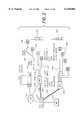
- FIG. 1is a diagram of a pattern of cells in a wireless communication system.
- FIG. 2is a block diagram of a communication system.
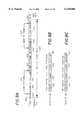
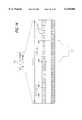
- FIG. 3is an illustration of a timing pattern according to existing GSM standards.
- FIG. 4is a block diagram of a transmitter and a receiver in a spread spectrum communication system.
- FIG. 5is a diagram of an arrangement of cells in a wireless communication system showing an exemplary code and frequency reuse pattern.
- FIG. 6is a diagram of a time frame divided into a plurality of time slots.
- FIG. 7is a diagram of an alternative timing structure showing a time frame divided into a plurality of virtual time slots.
- FIG. 8is a diagram illustrating a protocol for establishment of a spread spectrum communication link in a particular communication system.
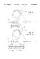
- FIG. 9Ais a diagram of a preferred slot structure for a time slot according to a particular TDMA protocol.
- FIGS. 9B and 9Care diagrams of a base station traffic message structure and a user station traffic message structure, respectively, in the same TDMA protocol.
- FIGS. 10A-10Care diagrams of preferred polling message formats for use in the TDMA protocol related to FIGS. 9A-9C.
- FIGS. 11A and 11Bare diagrams of preferred message header formats for use in the TDMA protocol related to FIGS. 9A-9C.
- FIGS. 12A and 12Bare diagrams of a base station information packet and a user station information packet, it respectively, for use in the TDMA protocol related to FIGS. 9A-9C.
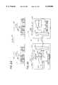
- FIG. 13is a diagram of an integrated base station according to one embodiment of the present invention.
- FIG. 14is a timing diagram of a comparing the timing structure of two different communication protocols.
- FIG. 15is a timing diagram of a composite time frame shown relative to the timing structure of the communication protocols of FIG. 14.
- FIG. 16is a timing diagram of a different composite time frame shown relative to the timing structure of the communication protocols of FIG. 14.
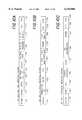
- FIGS. 17A and 17Bare demand migration tables showing, for a composite time frame, possible time slot allocations for the two communication protocols of FIG. 14.
- FIG. 18is a timing diagram showing waveforms for a slot clock and a frame clock.
- FIG. 19is a frequency channelization plan for a particular TDD communication system.
- FIG. 20is a frequency channelization plan for a GSM communication system.
- FIGS. 21 and 22are graphs showing, for a particular embodiment, a frequency channelization relationship for the communication systems having the frequency channelization plans shown in FIGS. 19 and 20.
- FIG. 23is a graph showing the frequency usage of a portion of the frequency spectrum during a non-GSM time slot of a composite time frame.
- FIG. 24Ais a diagram showing a timing relationship between the time frame structure of FIG. 7 utilizing virtual time slots and the GSM time frame structure;
- FIG. 24Bis a diagram of a composite time frame shown relative to the timing structures of FIG. 24A.
- FIG. 25is a diagram of an integrated base station with a dynamic slot allocation capability.
- FIG. 26is a timing diagram showing a "composite" time frame derived from the time frames of two protocols and having conditional time gaps inserted.
- FIG. 27is a diagram of a "composite" time frame comprising a plurality of time slots from two different protocols without regard to the time frame structure of the two protocols.
- FIG. 1is a diagram of a pattern of cells in a wireless communication system 101 for communication among a plurality of user stations 102.
- the wireless communication system 101 of FIG. 1includes a plurality of cells 103, each with a base station 104, preferably located at or near the center of the cell 103.
- Each station(both the base stations 104 and the user stations 102) generally comprises a receiver and a transmitter.
- a control station 105(sometimes referred to herein as a "base station controller”), also comprising a receiver and a transmitter, manages the resources of the system 101.
- FIG. 2is a block diagram of a communication system architecture utilized in a preferred embodiment of the present invention.
- the FIG. 2 communication systemcomprises a plurality of base stations 104 for communicating with a plurality of user stations 102.
- the base stations 104 and user stations 102may operate in a personal communications system (PCS), under rules prescribed by the Federal Communications Commission (FCC).
- PCSpersonal communications system
- FCCFederal Communications Commission
- Each base station 104is preferably coupled to a base station controller 105 by any of a variety of communication paths 109.
- the communication paths 109each comprise one or more communication links 118.
- Each communication link 118may include a coaxial cable, a fiber optic cable, a digital radio link, or a telephone line.
- Each base station controller 105is preferably connected to one or more communication networks 126, such as a public switched telephone network (PSTN) or personal communication system switching center (PCSC), by one or more communication paths 108, each of which may include a coaxial cable, a fiber optic cable, a digital radio link, or a telephone line.
- PSTNpublic switched telephone network
- PCSCpersonal communication system switching center
- the FIG. 2 communication systemalso may include one or more "intelligent" base stations 107 which connect directly to a communication network 126 without interfacing through a base station controller 105.
- the intelligent base stations 107bypass the base station controllers 105 for local handoffs and switching of user stations 102, and instead perform these functions directly over the network 126.
- each base station 104formats and sends digital information to its respective base station controller 105 (or directly to the network 126 in the case of an intelligent base station 107).
- the base station controllers 105receive inputs from multiple base stations 104, assist handoffs between base stations 104, and convert and format channel information and signaling information for delivery to the network 126.
- the base station controllers 105may also, if desired, manage a local cache VLR database, and may support basic operation, administration and management (OA&M) functions such as billing, monitoring and testing.
- Each base station controller 105under control of the network 126, preferably manages local registration and verification of its associated base station 104 and may provide updates to the network 126 regarding the status of the base stations 104.
- the network 126connects to the base station controllers 105 for call delivery and outgoing calls.
- Intelligent base stations 107may use a predefined signaling protocol--such as ISDN messaging--for registration, call delivery and handoff over a public telephone switch.
- the intelligent base station 107has all the general capabilities of a base station 104, but further may incorporate a BRI card, additional intelligence and local vocoding.
- base stations 104preferably connect to the network 126 through a defined "AA" interface.
- the "A” interfacemay be incorporated in base station controllers 105 and in intelligent base stations 107.
- Features and functionality of GSMare passed to and from the base stations it 104 over the "A" interface in a manner that is transparent to the end user.
- the systemmay also interconnect to cable television distribution networks.
- the base stations 104may be miniaturized so that they can be installed inside standard cable TV amplifier boxes. Interfacing may be carried out using analog remote antenna systems and digital transport mechanisms. For example, T1 and FT1 digital multiplexer outputs from the cable TV network may be used for interfacing, and basic rate (BRI) ISDN links may be used to transport digital channels.
- BRIbasic rate
- FIG. 13is a diagram of an integrated base station 850 (which can be either a base station 104 or an intelligent base station 107 in FIG. 2) in accordance with one embodiment of the present invention.
- the integrated base station 850comprises a first base station unit 852 and a second base station unit 853.
- each base station unit 852, 853is capable of carrying out communication with a plurality of user stations 102 according to multiple communication protocols (e.g., two protocols).
- the first base station unit 852preferably carries out communication with a plurality of user stations 102 using a first protocol
- the second base station unit 853preferably carries out communication with a plurality of user stations 102 using a second protocol.
- User stations 102may be configured for communication using either the first protocol, the second protocol, or both protocols, as further illustrated herein.
- the first protocolis a GSM protocol generally utilizing FDD/TDMA techniques
- the second protocolis a TDMA or TDD protocol having properties allowing it to smoothly integrate with the GSM protocol.
- a user station 102 desiring to communicate with the integrated base station 850may utilize either protocol to do so (assuming channel availability)
- protocol to do soassuming channel availability
- FIG. 3illustrates a timing pattern according to certain existing GSM standards. According to these standards, communication between a base station 104 and user stations 102 is divided into eight burst periods 152. Up to eight different user stations can communicate with a base station, one in each burst period 152.
- GSM standardsinclude the use of two separate frequency bands.
- the base station 104transmits to a user station 102 using a frequency channel on a first frequency band F A , while the user stations 102 transmit using an assigned frequency channel on a second frequency band F B .
- the user station 102shifts in frequency by a predefined amount (e.g., 40 MHz or 80 MHz) to the second frequency band F B and transmits a user transmission 156 in response to the base transmission 155 approximately three burst periods 152 later.
- the three burst period delayis assumed to be large enough to account for propagation time and other delay periods between the base station 104 and the user station 102.
- Each GSM burst period 152is surrounded by guard times 157 to account for uncertain signal propagation delays between the base station 104 and the user station 102.
- the base station 104may command the user station 102 to advance or retard its transmission timing in order to fall within the proper burst period 152, a feature known as adaptive frame alignment.
- a specification relating to adaptive frame alignment for the GSM systemis TS GSM 05.10.
- a second preferred protocolis a TDD/TDMA protocol utilizing aspects of spread-spectrum technology and/or code division multiplexing, as well as frequency division multiplexing as further discussed herein.
- a spread-spectrum transmitter and receiverare described with respect to FIG. 4, and preferred TDD timing structures are described hereafter with respect to FIGS. 6 and 7.
- FIG. 4is a block diagram of an exemplary transmitter and receiver in a spread spectrum communication system as may be employed for spreading and despreading signals in a spread spectrum communication system.
- a spread-spectrum transmitter 201comprises an input port 202 for input data 203, a chip sequence transmitter generator 204, a modulator 205, and a transmitting antenna 206 for transmitting a spread-spectrum signal 207.
- a spread-spectrum receiver 208comprises a receiver antenna 209, a chip sequence receiver generator 210, a demodulator 211, and an output port 212 for output data 213.
- a single chip sequence 214is identically generated by both the transmitter generator 204 and the receiver generator 210, and appears essentially random to others not knowing the spreading code upon which it is based.
- the spread-spectrum signal 207is despread with demodulator 211 by correlating the received signal with a locally generated version of the chip sequence 214.
- Exemplary correlatorsare described in, e.g., U.S. Pat. Nos. 5,022,047 and 5,016,255, each of which are incorporated by reference as if fully set forth herein.
- a preferred method for despreading and correlating spread spectrum signalsis described in U.S. patent application Ser. No. 08/481,613 filed Jun. 7, 1995, which is hereby incorporated by reference as if set forth fully herein.
- the control station 105assigns the base station 104 transmitters and user station 102 transmitters in each cell 103 a spread-spectrum code for modulating radio signal communication in that cell 103.
- the resulting signalis generally spread across a bandwidth exceeding the bandwidth necessary to transmit the data, hence the term "spread spectrum". Accordingly, radio signals used in that cell 103 are spread across a bandwidth sufficiently wide that both base station 104 receivers and user station 102 receivers in an adjacent cell 103 may distinguish communication which originates in the first cell 103 from communication which originates in the adjacent cell 106.
- FIG. 5is a diagram of a preferred cellular environment in which the spread spectrum protocol operates.
- a geographical region 301is divided into a plurality of cells 103.
- Associated with each cell 103is an assigned frequency and an assigned spread spectrum code.
- Preferably, three different frequencies (or frequency groups) F1, F2 and F3are assigned in such a manner that no two adjacent cells have the same assigned frequency (or frequency group) F1, F2 or F3, thereby minimizing interference between adjacent cells.
- different near-orthogonal spread spectrum codes C1 through C7are assigned as shown in a repeating pattern overlapping the frequency reuse pattern. Although seven spread spectrum codes C1 through C7 are shown in FIG. 5, a pattern involving other numbers of spread spectrum codes may be suitable depending upon the particular application.
- FIG. 6is a diagram showing a preferred timing structure for a TDD system. According to the timing structure of FIG. 6, communication over time is broken into a continuous series of time frames 301. A single complete time frame 301 is shown along a timeline 310 in FIG. 6; similar time frames precede and follow time frame 301 in a continuous pattern along the timeline 310.
- Time frame 301is divided into a plurality of time slots 302 numbered consecutively TS1, TS2 . . . TSN, each of which may support duplex communication with a user station 102.
- Time frame 301may be thought of as a "polling loop" or a time loop, as depicted in FIG. 6, whereby a base station 104 communicates with user stations 102 sequentially over the time frame 301 in a manner analogous to polling, each user station 102 transmitting and receiving messages in its designated time slot 302.
- FIG. 6Time frame 301 may be thought of as a "polling loop" or a time loop, as depicted in FIG. 6, whereby a base station 104 communicates with user stations 102 sequentially over the time frame 301 in a manner analogous to polling, each user station 102 transmitting and receiving messages in its designated time slot 302.
- each time slot 302comprises a user segment 305, wherein a user station 102 transmits a user-to-base message to the base station 104, and a base segment 306, wherein the base station 104 transmits a base-to-user message to the user station 102.
- Communication in time slots 302may be interleaved, such that user stations 102 transmit in one physical time slot 302 but receive in a different physical time slot 302 (such as described with respect to the FIG. 7 timing structure elsewhere herein).
- time frames 301are each 18.46 milliseconds in duration, and each time frame 301 comprises sixteen time slots 302 or, alternatively, eight time slots 302 to support extended range through increased guard times. If sixteen time slots 302 are used, the time slots 302 are preferably each 1153.125 microseconds in duration.
- a user station 102may communicate in more than one time slot 302 in each time frame 301, so as to support an increased data rate. Similarly, in some embodiments, a user station 102 may periodically skip time frames 301 and communicate in a subset of all time frames 301 (e.g., every other time frame 301, or every fourth time frame 301), so as to support a reduced data rate where a full speed communication link is not necessary. Further information about an exemplary TDMA system supporting variable data rates may be found in copending U.S. patent application Ser. No. 08/284,053 filed Aug. 1, 1994, which application is hereby incorporated by reference as if fully set forth herein.
- FIG. 7is a diagram of an alternative preferred timing structure employing virtual time slots, each of which generally comprises a duplex pair of communication links (i.e., one forward link and one reverse link).
- FIG. 7similar to FIG. 6, communication over time is broken into a continuous series of time frames 601.
- a single complete time frame 601is shown along a timeline 610 in FIG. 7; similar time frames precede and follow time frame 601 in a continuous pattern along the timeline 610.
- Time frame 601is divided into a plurality of physical time slots 602 numbered consecutively TS1', TS2' . . . TSN'.
- Each physical time slot 602comprises a user segment 605 wherein a user station 102 transmits a user-to-base message to the base station 104, and a base segment 606 wherein the base station 104 transmits a base-to-user message to a user station 102, which could be a different user station 102 than transmitted to the base station 104 in the same physical time slot 602.
- communication in physical time slots 602may be interleaved, such that a user station 102 transmits in one physical time slot 602 but receives in a different physical time slot 602.
- the user segment 605 and base segment 606which define the forward link and reverse link transmissions to a given user station 102 (and which are typically located in different physical time slots 602) are referred to as a virtual time slot.
- FIG. 7An exemplary virtual time slot 618 is shown in FIG. 7, associated with a particular user station 102 (e.g., user station MS2).
- the virtual time slot 618comprises two message segments, one in each of two physical time slots 602a and 602b.
- Virtual time slot 618has a user segment 605a in the first physical time slot 602a, and a base segment 606b in the second physical time slot 602b.
- the base station 104transmits in a base segment 606a of the first physical time slot 602a (e.g., to a second user station 102, such as user station MS1), and another user station 102 (e.g., a third user station 102, such as user station MS3) transmits in a user segment 605b to the base station 104. In this manner, transmissions to and from the base station 104 are interleaved.
- Time frame 601may be thought of as a "polling loop" or a time loop, similar to time frame 301 of the FIG. 6 embodiment, whereby a base station 104 communicates with user stations 102 sequentially over the time frame 601 in a manner analogous to polling, each user station 102 transmitting and receiving messages in its designated virtual time slot 618.
- the virtual time slots 618 of FIG. 7, however,are not necessarily identical to the physical time slots 602.
- An advantage of the FIG. 7 timing structureis that it generally provides extended time for the base station 104 to process channel characterization data received from the user station 102.
- time frames 601are each 18.46 milliseconds in duration, and each time frame 601 comprises sixteen time slots 602 or, alternatively, eight time slots 602 to support extended range through increased guard times. If sixteen time slots 602 are used, the time slots 602 are preferably each 1153.125 microseconds in duration.
- a user station 102may communicate in more than one virtual time slot 618 in each time frame 601, so as to support an increased data rate. Similarly, in some embodiments, a user station 102 may periodically skip time frames 601 and communicate in some subset of all time frames 601 (e.g., every other time frame 601, or every fourth time frame 601), so as to support a reduced data rate where a full speed communication link is not necessary.
- Communication between a user station 102 and a base station 104is established in one embodiment by a response from a user station 102 to a general polling message sent from the base station 104 during an available time slot 302.
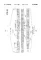
- FIG. 8illustrates a protocol for establishment of a spread spectrum communication link in, e.g., the FIG. 6 communication system.
- a communication linkmay be established in an analogous manner for the FIG. 7 embodiment.
- messagesare generally one of three types: a general poll message 401, a specific poll message 402, or an information message 403.
- a messageWhen a message is transmitted by a user station 102, it may be referred to herein as a "response", e.g., a general poll response 404, a specific poll response 405, or an information response 406.
- a general poll message 401is transmitted by the base station 104 in each time slot 302 available for communication.
- a user station 102 seeking to establish communicationmonitors transmissions from a base station 104 and ascertains available time slots 302 by receiving general poll messages 401 in those time slots 302.
- a user station 102"acquires" a base station 104 by a sequence of handshaking steps.
- the base station 104transmits a general poll message 401 during an unoccupied time slot 302.
- the user station 102receives the general poll message 401 and, if it was received without error, transmits a general poll response 404 to the base station 104 in the same time slot 302 of the following time frame 301.
- the general poll message 401comprises a field for a base ID 408b, which may be 32 bits long, and which may be recorded by the user station 102.
- the general poll response 404comprises a field for a user ID 409, which is preferably 72 bits long, and which may be recorded by the base station 104.
- the base station 104Upon receiving a general poll response 404, at a specific poll step 410, the base station 104 transmits a specific poll message 402, comprising the user ID 409 received by the base station 104 as part of the general poll response 404.
- the user station 102receives the specific poll message 402 and, if it was received without error and with the same user ID 409, transmits its specific poll response 405 to the base station 104 in the same time slot 302 of the following time frame 301.
- the specific poll response 405comprises the same user ID 409 as the general poll response 404.
- the specific poll message 402may be eliminated as redundant.
- the user station 102may therefore follow the general poll response 404 with a specific poll response 405.
- the base station 104may transmit a traffic message 403.
- the base station 104 and user station 102have established a communication link 412.
- the base station 104may couple a telephone line to the communication channel, and the user station 102 may begin normal operation on a telephone network (e.g., the user station 102 may receive a dial tone, dial a number, make a telephone connection, 101, and perform other telephone operations).
- the base station 104 and user station 102may exchange traffic messages 403 and 406, until the communication link 412 is voluntarily terminated, until faulty communication prompts the user station 102 to re-acquire the base station 104, or until handoff of the user station 102 to another base station 104.
- the base station 104may advertently fail to respond.
- the lack of response from the base station 104signals the involved user stations 102 to back off for a calculated time interval before attempting to acquire the same base station 104 using the general poll message 401 and general poll response 404 protocol.
- the back-off timemay be based upon the user ID 409, and therefore each user station 102 will back off for a different length of time to prevent future collisions.
- the base station 104transmits a specific poll message 402 with the user ID 409 of the indicated recipient user station 102 (skipping the general poll message 401 and the general poll response 404) on an available time slot 302.
- Each user station 102listens regularly for the specific poll message 402, as further described herein, so as to receive the specific poll message 402 within a predetermined time after it is transmitted.
- the user station 102compares the user ID 409 in the message with its own user ID, and if they match, continues with the link-established step 411.
- the base station 104may thus establish a communication link 412 with any user station 102 within communication range.
- the general poll message 401comprises a slot pointer (e.g., in slot pointer field 810 shown in and described hereafter with respect to FIG. 11A) which indicates the next time slot 302 (or virtual time slot 618) during which the next general poll message 401 will be transmitted by the base station 104.
- a user station 102 seeking to establish communicationresponds to the general poll message 401 not necessarily in the same time slot of the next time frame 301 (or 601), but in the user segment 305 (or 605) of the time slot 302 (or 618) indicated by the slot pointer.
- the base station 102Upon receiving a general response message 404 from the user station 102 in the time slot indicated by the slot pointer, the base station 102 responds with a specific poll message 402.
- the specific poll message 402comprises a temporary shorthand identifier (nickname) specific to the user station 102 and known as a correlative ID.
- the correlative IDappears in future signaling messages (in both directions) until the established link is dropped.
- the user station 102responds with a traffic message in a time slot 302 (or 618) assigned by a slot pointer in the header of the specific poll message 402.
- FIG. 9Ais a diagram of a preferred slot structure
- FIGS. 9B and 9Care diagrams of a base station traffic message structure and a user station traffic message structure, respectively.
- a time slot 510comprises a variable radio delay gap 505, a user station transmit frame 515, a user station turn-around gap 525, a guard time 535, a base station transmit frame 545, and a base station turn-around gap 555.
- Each user station transmit frame 515comprises a user preamble 516, a user preamble sounding gap 519, and a user station data frame 521.
- each base station transmit frame 545comprises a base preamble 547, a base preamble sounding gap 549, and a base transmit data frame 551.
- FIG. 9Billustrates a preferred message structure for the base transmit data frame 551.
- the message structure of FIG. 9Bcomprises a base header field 553, a base D-channel field 557, a base data field 559, and a base cyclical redundancy check (CRC) field 561.
- the base header field 553is 23 bits
- the base D-channel field 557is 8 bits
- the base data field 559is 192 bits
- the base CRC field 561is 16 bits.
- FIG. 9Cillustrates a preferred message structure for the user station transmit data frame 521.
- the message structure of FIG. 9Ccomprises a user header field 523, a user D-channel field 527, a user data field 529, and a user CRC field 531.
- the user header field 523is 17 bits
- the user D-channel field 527is 8 bits
- the user data field 529is 192 bits
- the user CRC field 531is 16 bits.
- a time slot 301comprises 3125 chip periods (where each chip period is equal to about 0.369 microseconds); the user transmit frame 515 and the base transmit frame 545 are 519.552 microseconds (1408 chips in duration) and 531.36 microseconds (1440 chips in duration), respectively; the user station turn-around gap 525 is 10.7 microseconds (29 chips in duration); the guard time 535 is 66.4 microseconds (180 chips in duration); and the base station turn-around gap 555 is 25.1 microseconds (68 chips in duration).
- the effective gap timeis 72.3 microseconds, corresponding to a non-interfering base-station-to-base-station range of about 13.5 miles.
- the bearer channeli.e., user data field 529) supports a rate of 10,400 bits/second, and the D-channel 527 supports a data rate of 433.33 bits/second.
- FIGS. 10A-10Care diagrams of preferred polling message formats.
- FIG. 10Ais a diagram of a general poll message format (such as for general poll message 401 of FIG. 8).
- the general poll message 701preferably comprises, in the following sequence, a header field 702, a spare field 703, a zone field 704, a base station controller (BSC) ID field 705, a base ID field 706, a facility field 707, a system type field 708, a service provider field 709, a slot quality field 710, a forward error correction (FEC) field 711, and a frame control word (FCW) field 712.
- BSCbase station controller
- FECforward error correction
- FCWframe control word
- the header field 702is 23 bits long
- the spare field 703is 16 bits long
- the zone field 704is 40 bits long
- the BSC ID field 705is 16 bits long
- the base ID field 706is 32 bits long
- the facility field 707is 32 bits long
- the system type field 708is 8 bits long
- the service provider field 709is 16 bits long
- the slot quality field 710is 8 bits long
- the FEC field 711is 32 bits long
- the frame control word field 712is 16 bits long, for a total of 239 bits.
- the header field 702identifies the message type and is described more fully with respect to FIG. 11A.
- the zone field 704identifies the paging zone of the specific base station 104. A user station 102 may move from one base station 104 service area to another in the same zone without requiring immediate re-registration.
- the BSC ID field 705is a sequence uniquely identifying the base station controller 105.
- the base ID field 706is a sequence uniquely identifying the base station 104.
- the facility field 707describes the services offered by the base station 104 (e.g., ethernet access, aggregate data capability, enhanced voice, etc.).
- the facility field 707may include a sub-field indicating which user stations 102 are permitted access to the channel (e.g., 911 calls only, or user stations 102 with specific access codes).
- the system type field 708identifies the type of system associated with the base station 104.
- the service provider field 709identifies the PCS service provider that operates the base station 104.
- the slot quality field 710indicates the relative quality of the time slot in terms of interference. Generally, the lower the number, the better the slot quality.
- the FEC field 711is used for forward error correction.
- the FCW field 712is used for error detection, and in one embodiment comprises a sequence determined according to following algorithm:
- the seed polynomial SDPis:
- FIG. 10Bis a diagram of a specific poll message format (such as for specific poll message 402 of FIG. 8).
- the specific poll message 720preferably comprises, in the following sequence, a header field 721, a correlative ID field 722, a cause field 723, a personal identifier (PID) field 724, an over-the-air (OTA) map type field 725, an OTA map field 726, a spare field 727, a slot quality field 728, a forward error correction field 729, and an FCW field 730.
- PIDpersonal identifier
- OTAover-the-air
- the header field 721is 23 bits long
- the correlative ID field 722is 8 bits long
- the cause field 723is 8 bits long
- the PID field 724is 72 bits long
- the OTA map type field 725is 8 bits long
- the OTA map field 726is 32 bits long
- the spare field 727is 32 bits long
- the slot quality field 728is 8 bits long
- the FEC field 729is 32 bits long
- the FCW field 729is 16 bits long, for a total of 239 bits.
- the header field 721, slot quality field 728, FEC field 729, and FCW field 730are similar to the analogous fields described for FIG. 10A.
- the correlative ID field 722is used to temporarily identify one or more channels (i.e., time slots) as being allocated to a specific user station 102.
- a correlative ID numberis assigned for the duration of a call connection and is released for reuse by another user station 102 at the termination of a connection; the correlative ID number may also be changed during a connection.
- a specific correlative ID numbermay be CF reserved by the base station 104 for broadcast use.
- the cause field 723indicates the cause of an error occurring during execution of a previous signaling traffic operation for the particular user station 102.
- the interpretation of the cause field 723 messagemay therefore depend upon the type of signal traffic involved. Possible cause messages include, for example, those indicating that the user station 102 is unregistered or will not be accepted for registration, or that the call has not been connected or cannot be completed.
- the PID field 724comprises a personal identification number which uniquely identifies the subscriber (e.g., user station 102).
- the OTA map type field 725defines the type of map (e.g., superframe, subframe, etc.) that follows in the OTA map field 726.
- the OTA map field 726describes the mapping of time slots relative to a particular user station 102. The format of the OTA map field 726 depends on the map type.
- FIG. 10Cis a diagram of a poll response message format (such as for general poll response 404 or specific poll response 405 of FIG. 8).
- the poll response message 740preferably comprises, in the following sequence, a header field 741, a first spare field 742, a PID field 743, a service provider field 744, a class field 745, a user capabilities field 746, a second spare field 747, an FEC field 748, and an FCW field 749.
- the header field 741is 17 bits long
- the first spare field 742is 16 bits long
- the PID field 743is 72 bits long
- the service provider field 744is 16 bits long
- the class field 745is 16 bits long
- the user capabilities field 746is 16 bits long
- the second spare field 747is 32 bits long
- the FEC field 748is 32 bits long
- the FCW field 749is 16 bits long, for a total of 233 bits.
- the header field 741identifies the message type and is more fully described in FIG. 11B.
- the PID field 743, FEC field 748, and FCW field 746are similar to the PID field 724, FEC field 729, and FCW field 730, respectively, described with respect to FIG. 10B.
- the service provider field 744identifies the PCS service provider that the user station 102 wishes to use.
- the class field 745specifies some of the operational parameters being used by the particular user station 102.
- the class field 745may comprise a class type sub-field and a class information sub-field.
- the class type sub-fieldindicates the user station class type (e.g., GSM or DCS1900 class type, IS-41 class type, etc.).
- the class information sub-fieldprovides operational information including, for example, revision level, available encryption algorithms, short message capability, ellipsis notation and phase-2 error handling capability, power class, continuous/discontinuous transmission, bandwidth (e.g., 20 MHz or 25 MHz), and nominal power levels.
- the user capabilities field 746identifies the features present in the user station 102 (e.g., whether the user station 102 can receive a fax or data connection, whether the user station 102 is capable of ciphering, etc.).
- FIGS. 11A and 11Bare diagrams of preferred polling message header formats.
- FIG. 11Ais a diagram of a polling message header format for a base polling message (such as general poll message 401 or specific poll message 402 of FIG. 8).
- the polling message header 801comprises a base/mobile indicator (B/M) flag 802, an extended protocol (E) flag 803, a packet type field 804, a power adjustment (PWR) field 805, a symmetry field 806, a D-channel suppression (DCS) flag 807, a virtual slot (VS) flag 808, a slot or channel utilization (CU) field 809, a slot pointer field 810, a error check and correct (ARQ) field 811, and a header frame control word (HCF) field 812.
- B/Mbase/mobile indicator
- Eextended protocol
- PWRpower adjustment
- DCSD-channel suppression
- VSvirtual slot
- CUslot pointer field
- ARQerror check and correct
- HCFheader frame control word
- the B/M indicator flag 802, E flag 803, PWR field 805, DCS flag 807, and the VS flag 808are each 1 bit long
- the packet type field 804 and symmetry fieldare each 2 bits long
- the CU field 809 and ARQ fieldare each 3 bits long
- the slot pointer field 810 and header HCF field 812are each 4 bits long, for a total of 23 bits.
- a twenty-fourth bit of the header 801is "lost" in establishment of the RF link due to the use of differential phase encoding to transmit six bits of data per symbol code.
- the B/M indicator flag 802indicates whether the originator of the message is a user station 102 or the base station 104.
- the E flag 803is used to indicate whether or not an extended protocol is in use.
- the packet type field 804specifies which of four packet types is being used, according to Table 8-1A below.
- the packet type field 804also provides an indication of the usage of the D-field 557, according to Table 8-1B below.
- the PWR field 805is a serialized bit stream from the base station 104 to the user station 102 allowing control of the power level of the user station 102 transmitter. As each base-to-user message is received at the user station 102, the PWR bit from the last message is analyzed along with the current PWR bit to determine if the power level of the user station 102 transmitter should be raised, lowered or remain unchanged. Power control action therefore requires that at least two consecutive base-to-user messages be received by the user station 102 before any action is taken. The action taken is dictated according to Table 8-2 appearing below.
- the amount of power increase or decrease carried out in response to receiving commands in the PWR field 805may be a fixed or preset amount--e.g., 1 dB for each time frame 301 (or more frequently if the user station 102 is transmitting in multiple time slots 302 per time frame 301).
- Using only a single bit for the PWR field 805saves space in the header 553 of the base-to-user message. Performance is adequate because the quality metrics generally provide sufficient feedback to allow small power adjustment steps over time, but not sufficient feedback to have confidence in making substantial power adjustment steps.
- the symmetry field 806is used by the base station 104 to grant bandwidth to the user station 102.
- the bandwidth grantapplies to the next time slot 302 (or 618) in the channel.
- the symmetry field 806 contentsmay be interpreted according to Table 8-3 below.
- the DCS flag 807indicates the usage of the D-channel for the current message.
- the DCS flag 807is set to one value to indicate that the D-channel is disabled to reserve it for use by the application using the bearer channel (B-channel), and is set to another value to indicate that the D-channel is enabled for other usage.
- the VS flag 808indicates whether the base station 104 is using a virtual slot mode. If the virtual slot mode is active (e.g., the time slot structure of FIG. 6 is used), then all user station 102 transmissions occur one time slot earlier than if the VS mode is inactive.
- the CU field 809indicates the relative slot utilization for the base station 104.
- the CU field contentsare defined according to Table 8-4 below.
- access leveling and load leveling classesmay be identified in the facility field 707 of the general poll message (see FIG. 10A).
- the slot pointer field 810contains an index which identifies the next time slot to be used in the current base/user packet exchange.
- the user station 102must transmit in the indicated time slot to continue the exchange.
- the contents of the slot pointer field 810may take on any of sixteen different values (e.g., binary 0 to 15), with each value indicating a number of time slots from the present time slot in which the user station 102 is to transmit. For example, a value of zero means that the user station 102 is to transmit in the same slot (in the next frame if at a regular bandwidth rate, or several frames in the future if using a sub-frame rate). A value of one means that the user station 102 is to transmit in the next time slot of the present time frame.
- a value of twomeans that the user station 102 is to transmit in the time slot two places ahead in the present time frame, and so on.
- the ARQ field 811allows the receiving entity (either base station 104 or user station 102) to correct a message error.
- the ARQ field 811comprises three subfields of one bit each: (1) an "ARQ required" sub-field that indicates whether or not ARQ is required for the message sent; (2) an "ACK" sub-field indicating whether or not the sender of the message received correctly the last message sent; and (3) a "message number" sub-field, which indicates the message number (zero or one) of the current message.
- the ACK sub-field and message number sub-fieldare preferably always used regardless of whether the ARQ required bit is set.
- the receiving entityperforms the following steps:
- the header HCF field 812is used for a cyclic redundancy check calculated over the 12 preceding bits (i.e., the preceding bits of the message header).
- FIG. 11Bis a diagram of a polling message header format for a poll response message (such as general poll response 404 or specific poll response 405 of FIG. 8).
- the polling response header 820comprises a base/mobile indicator (B/M) flag 821, an extended protocol (E) flag 822, a packet type field 823, a PWR field 824, a symmetry field 825, a DCS flag 826, a spare field 827, an ARQ field 828, and a header frame control word (HCF) field 829.
- the B/M indicator flag 821, E flag 822, and DCS flag 826are each 1 bit long
- the packet type field 823, symmetry field 825, and spare field 827are each 2 bits long
- the ARQ field 828is 3 bits long
- the HCF field 829is 4 bits long, for a total of 17 bits.
- An eighteenth bitis "lost" in the establishment of the RF link due to the use of differential phase encoding to transmit six bits per symbol code.
- the B/M indicator flag 821, E flag 822, packet type field 823, PWR field 824, DCS flag 826, ARQ field 828 and HCF field 829are used for the same purposes as their counterpart fields in the base station header shown in FIG. 11A.
- the contents of the symmetry field 825 in the user station 102 headermay be interpreted according to Table 8-5 below.
- FIG. 12Ais a diagram of a base station information packet showing in octet format fields generally depicted in FIGS. 9B and 11A.
- FIG. 12Bis a diagram of a user station information packet showing in octet format fields generally depicted in FIGS. 9C and 11B.
- Datamay be transmitted between the base station 104 and user stations 102 using an M-ary spread spectrum technique.
- M-ary spread spectrum transmission and reception techniquesare described in, e.g., U.S. Pat. No. 5,022,047 and in U.S. patent application Ser. No. 08/484,007 filed Jun. 7, 1995, both of which are incorporated by reference as if set forth fully herein.
- phase encodingis also preferably used to allow transmission of a 6th bit of data for each symbol code.
- Techniques of phase encoding for transmission of an additional bit of information per symbol codeare described in, e.g., U.S. patent application Ser. No. 08/484,007.
- the base header field 553Because the base header field 553 is positioned first in the base transmit data frame 551, it loses the first bit from the first transmitted data symbol (which is transmitted using a differential encoding technique). Thus the base header field 553, which comprises four data symbols, is 23 bits in length. The first symbol comprises five data bits, and the latter three symbols each comprises six data bits. Likewise, because the user header field 523 is positioned first in the user transmit data frame 521, it loses the first bit from the first transmitted data symbol. Thus the user header field 523, which comprises three symbols, is 17 bits in length. The first symbol comprises five data bits, and the latter two symbols each comprises six data bits.
- User stations 102 in one embodimentmay comprise mobile handsets capable of multi-band and/or multi-mode operation.
- the user stations 102may be multi-mode in that they may be capable of both spread spectrum (i.e., wideband) communication and also narrowband communication.
- the user stations 102may be multi-band in the sense that they may be set to operate on a plurality of different frequencies, such as frequencies in either the licensed or unlicensed PCS bands.
- the user stations 102may operate in one mode (e.g., wideband) over a first frequency band, and another mode (e.g., narrowband) over a second frequency band.
- a user station 102may be set to operate on a plurality of frequencies between 1850 and 1990 MHz, with the frequencies separated in discrete steps.
- Each user station 102may be equipped with a frequency synthesizer that can be programmed to allow reception and/or transmission on any one of the plurality of frequencies.
- the programmable frequency stepsare in 200 KHz increments (for GSM or narrowband communication) or 1.8 MHz increments (for spread spectrum communication) within the GSM frequency bands.
- the user station 102may also be configured to operate in the isochronous band between 1920 and 1930 MHz, having a first channel centered at 1920.625 MHz, and channel spacing of 1.25 MHz across the remainder of the isochronous band.
- channel informationis monitored to assist the base station 104 in selecting an antenna for communication with a user station 102.
- the channel informationcan also permit the base station 104 to adjust its own output power and that of the user station(s) 102.
- Time division duplexpermits common antennas to be used for transmit and receive functions at both the base station 104 and the user stations 102, typically without the need for antenna diplexers. Common antennas can be used to transmit and receive because these functions are separated in time at each of the user stations 102 and base stations 102. The use of common antennas results in simplicity of the base station 104 and user station 102 terminal designs.
- a base station 104preferably includes a plurality of base station antennas providing antenna diversity.
- the base station 104includes electronics for selecting the best antenna to be used for communication with each user station 102 during each time slot 302.
- the base station 104may receive a user transmission (such as a user-to-base message sent during a user segment 305 of a time slot 302) simultaneously (with possible variations due to reflection or multi-path effects) on each of a plurality of base station antennas.
- Each base station antenna i-sconnects to an individual base station receiver which analyzes the quality of the received user transmission and provides quality metrics to a processor in the base station 104.
- the base station 104compares the quality metrics produced by each base station receiver and selects the best quality receiver output signal. In this manner, the most appropriate base station antenna is selected for each user station 102.
- the metrics from the selected receiver output signalprovide a characterization of the communication channel between the base station 104 and the particular user station 102.
- the base station 104When the base station 104 transmits to a particular user station 102, it selects the most appropriate base station antenna for transmission.
- An antenna and a transmission power levelare preferably selected so as to match the characteristics of the transmission channel from the base station 104 to the user station 102.
- the base station 104may select as its transmitting antenna the same base station antenna selected to receive the user transmission 305. Because the base station 104 can both receive and transmit on the antenna having the best received signal quality from the user station 102, the user station 102 benefits from antenna diversity even if it does not have multiple antennas. Because the base station 104 transmits very quickly after receiving the user transmission, there is little time lag, so that the channel characteristics do not change significantly before the base station 104 makes its transmission.
- the base station 104again selects an antenna and power level for a base station transmission (such as a base-to-user message transmitted during a base segment 306 of a time slot 302) based on channel characterization data derived from the most closely preceding user station transmission.
- a base station transmissionsuch as a base-to-user message transmitted during a base segment 306 of a time slot 302
- the base station 104preferably controls its output power on a slot-by-slot basis. To do so, the base station 104 preferably has means to determine the power setting of the user station 102. However, because a single base station 104 can communicate during a polling loop 301 with a large number of user stations 102, each of whose distance from the base station 104 can vary from near zero up to the radius of the cell 103, control of the base station transmitter output power so as to maintain a near-constant received power level at each user station 102 during each time slot 302 may not be practical, largely due to the fact that large changes (e.g., more than 40 dB) in base station transmit output power would be necessary each time slot 302 (e.g., about every 1153 ⁇ s). As an alternative to providing power control on a time slot 302 by time slot 302 basis, output power control at the base station 104 can instead be averaged over a longer time interval than each time slot 302.
- the base station 104determines the quality of the received signal including, for example, the received power and the signal-to-noise or interference ratio.
- the base station 104in one embodiment sends a message to the user station 102 indicating the signal quality received by the base station 104, and commanding the user station 102 to adjust its power if needed.
- the base station 104Based on the quality of the received signal, the base station 104 in one embodiment commands the user station 102 to change (increase or decrease) its transmit power by some discrete amount (e.g, in minimum steps of 3 dB) relative to its current setting, until the quality of the user transmissions received by the base station 104 is above an acceptable threshold.
- some discrete amounte.g, in minimum steps of 3 dB
- a preferred power adjustment command from the base station 104 to the user station 102is encoded according to Table 8-2 appearing earlier herein. Although preferred values are provided in Table 8-2, the number of power control command steps and the differential therebetween may vary depending upon the particular application and the system specifications.
- aspects of the inventionare directed to facilitating rapid control traffic within the timing structure of the communication system.
- Handover, establishing communication, or time slot interchangemay be carried out in a rapid manner by utilizing multiple time slots spaced less than one time frame apart.
- the control traffictakes advantage of unused time slots to avoid having to wait an entire time frame for each opportunity to exchange messages between the base station 104 and the user station 102 desiring a transaction. Spare resources are thereby used for the purpose of speeding up control traffic transactions.
- the slot pointerallows the user station 102 to have knowledge of the next available time slot 302. Otherwise, the user station 102 may not necessarily know until a general poll message 401 is received whether or not a particular time slot is available for communication, and then would typically have to wait an entire polling loop before responding to the general poll message 401.
- the OTA map field 726describes the mapping of time slots relative to a particular user station 102.
- the OTA map field 726in one embodiment comprises sixteen bits. Each bit may be set to a first value (e.g., "1") to indicate that the time slot 302 associated with that bit is unavailable, and to a second value (e.g., "0") to indicate that the time slot 302 associated with that bit is available for communication.
- the time slot usageis indicated from a standpoint relative to the current time slot 302 of the user station 302--that is, the first bit is associated with the immediately following time slot, the second bit with the next time slot thereafter, the third bit with the next time slot thereafter, and so on.
- the time slot usagemay be indicated from a standpoint with respect to a fixed reference, such as the start of the time frame 301, in which case the user station 302 needs to have available as information the relative starting point of the time frame 301.
- FIG. 13is a block diagram of an integrated base station 850 in accordance with one embodiment of the present invention.
- Integrated base station 850comprises a first base station unit 852 operating according to a first TDMA or TDD protocol, and a second base station unit 853 operating according to a second TDMA or TDD protocol.
- the first base station unit 852 and second base station unit 853preferably operate in the same or overlapping geographic region.
- the first base station unit 852 and second base station unit 853, while shown as separate blocks in FIG. 13,may be physically located within the same unit. Alternatively, they may be at separate physical locations but nevertheless nearby one another.
- the first base station unit 852comprises a processor 860, a global positioning satellite (GPS) receiver 861, a clock generator 862, and a free slot index 863.
- the second base station unit 853comprises a processor 870 and a free slot index 873.
- the first base station unit 852communicates with the second base station unit 853 over communication lines 869. If the first base station unit 852 and second base station unit 853 are collocated, they may share the same antenna or set of antennas (not shown).
- the first base station unit 852communicates according to the communication protocol generally described with respect to FIG. 6 (or FIG. 7, and including FIGS. 8 through 12B; hereinafter collectively referred to as "the FIG. 6 communication protocol", or “the TDD protocol of FIG. 6", or simply “the TDD protocol”), and the second base station unit 853 communicates according to a GSM protocol.
- the FIG. 6 communication protocolor “the TDD protocol of FIG. 6", or simply “the TDD protocol”
- the second base station unit 853communicates according to a GSM protocol.
- interference between transmissions to and from the first base station unit 852 and the second base station unit 853are avoided by separating the communications in time according to a predefined timing pattern.
- timing patternencompassing one or more time frames of each of the communication protocols.
- a timing patternis hereinafter generally referred to as a composite time frame, as more fully explained further herein.
- Exemplary composite time framesare shown in FIGS. 15 and 16.
- FIG. 14is a diagram comparing time frames of two different protocols, from which the composite time frames of FIGS. 15 and 16 are derived.
- a first time frame 901designated a "Type-1" time frame
- the first time frame 901comprises a plurality of time slots 902.
- a second time frame 911designated a "Type-2" time frame.
- the second time frame 911also comprises a plurality of time slots 912.
- the time slots 902 of the first time frame 901are designated by "TS” followed by two digits (e.g., TS00, TS01, TS02, . . . , TS15), while the time slots 912 of the second time frame 911 are designated by "TS” followed by a single digit (e.g, TS1, TS2, TS3, . . . , TS7).
- TStime slots
- FIG. 14are numbered starting with “0” or "00”
- the time slotsare numbered starting with "1"; no implication by the particular starting reference numeral selected for a particular drawing is intended.
- the first time frame 901is defined as part of a protocol for TDD communication and, more particularly, the TDD protocol of FIG. 6.
- the second time frame 911is defined as part of the GSM protocol, as previously described with respect to FIG. 3.
- the first time frame 901has a duration of 18.46 milliseconds
- the second time frame 911has a duration of 4.615 milliseconds. Accordingly, four of the second time frames 911 in the aggregate have the same duration as a single first time frame 901.
- each of the time slots 902 of the first time frame 901has a duration of 1153.125 microseconds
- each of the time slots 912 of the second time frame 911has a duration of 576.92 microseconds. Accordingly, two of the latter time slots 912 in the aggregate have the same duration as a single of the first time slots 902.
- a composite time frame 925is defined with a portion of the composite time frame 925 time allocated to the first protocol, and a portion of the composite time frame 925 allocated to the second protocol.
- the first time frame 921i.e., time frame 901 of FIG. 14
- time slots 922which are unshaded to indicate their incorporation into the composite time frame 925, and shaded to indicate their exclusion from the composite time frame 925.
- a set of the second time frames 931i.e., time frames 911 of FIG.
- the composite time frame 925therefore comprises a plurality of different length time slots 926, some of which are time slots 926a corresponding to time slots 922 of the first time frame 921, and some of which are time slots 926b corresponding to the time slots 932 of the second time frame 931.
- the composite time frame 925comprises four time slots 926a corresponding to the first time frame 921 (i.e., time slots TS00, TS04, TS08, and TS12), and six time slots 926b corresponding to the second time frame 931 (i.e., time slots TS2 through TS7). Because of the timing relationship between the first time frame 921 and the second time frame 931, the first time slots 926a of the composite time frame 925 each appear once, and the second time slots 926b of the composite time frame 925 each appear four times (because the first time frame 921 covers four of the second time frames 931 in relative duration).
- time division communication according to both the first and second protocolsare by their nature periodic, and because the first time frame 921 in this embodiment covers four times the duration of the second time frame 931, the different sized time slots 926a, 926b of the composite time frame 925 will be interspersed according the periodic appearance of specific time slot channels taken from time frames 911 and 931.
- FIG. 16is a diagram of another composite time frame 945 having a different arrangement of time slots 946, each of the time slots 946 corresponding to time slots 922 or 932 of the first time frame 921 and second time frame 931.
- time slots 922 of the first time frame 921are unshaded to indicate their incorporation into the composite time frame 945, and shaded to indicate their exclusion from the composite time frame 945; similarly time slots 932 from the set of the second time frames 931 are unshaded to indicate their incorporation into the composite time frame 945, and shaded to indicate their exclusion from the composite time frame 945.
- the composite time frame 945therefore comprises a plurality of different length time slots 946, some of which are time slots 946a corresponding to time slots 922 of the first time frame 921, and some of which are time slots 946b corresponding to the time slots 932 of the second time frame 931.
- the composite time frame 945comprises eight time slots 926a corresponding to the first time frame 921 (i.e., time slots TS00, TS01, TS04, TS05, TS08, TS09, TS12 and TS13), and four time slots 926b corresponding to the second time frame 931 (i.e., time slots TS4 through TS7). Because of the timing relationship between the first time frame 921 and the second time frame 931, the first time slots 926a of the composite time frame 945 each appear once, and the second time slots 926b of the composite time frame 945 each appear four times (because the first time frame 921 covers four of the second time frames 931 in relative duration).
- the composite time frame 925can support up to four users of the first time slots 926a and six users of the second time slots 926b.
- the composite time frame 945can support up to eight users of the first time slots 946a and four users of the second time slots 926b.
- FIG. 17Ais a demand migration table showing how the ratio of number of supportable users of each protocol changes as the number of allocated time slots changes.
- the first row 950 of the demand migration table of FIG. 17Acorresponds to supportable users of the second protocol (i.e., the GSM protocol), and the second row 951 corresponds to supportable users of the first protocol (i.e., the TDD protocol of FIG. 6).
- Five different pairing options 954are provided for in the demand migration table of FIG. 17A, each with a different ratio of supportable GSM protocol users 952 to supportable TDD protocol users 953. As shown in FIG.
- first pairing option 954eight GSM protocol users 952 can be supported with zero TDD protocol users 953 supported in a composite time frame; under a second pairing option 954, six GSM protocol users 952 can be supported with four TDD protocol users 953 supported in a composite time frame; under a third pairing option 954, four GSM protocol users 952 can be supported with eight TDD protocol users 953 supported; and so on.
- the composite time frameshould be of a duration sufficient to fit an integral number of both the first and second time frames from which the composite time frame is derived.
- a composite time framemay be selected to be, e.g., 60 milliseconds, where the first time frame duration is 12 milliseconds and the second time frame is 20 milliseconds.
- the 60 millisecond composite time frame durationin such a case conveniently represents the shortest duration fitting an integral number of both a set of the first time frames and a set of the second time frames.
- FIG. 26is a diagram of a composite time frame 1085 illustrating such an arrangement.
- a series of first time frames 1080 having a first time frame durationare shown relative to a series of second time frames 1081 having a second time frame duration.
- the series of first time frames 1080are separated by time gaps 1082 of a duration selected so that two of the second time frames 1081 have the same duration as a single first time frame 1080 plus the time gap 1082.
- the composite time frame 1085is constructed in the same manner as described with respect to FIGS.
- time gaps 1082it is preferable to assign time slots of the second time frame 1081 starting from the end thereof (i.e., the region corresponding to the time gap 1082 inserted between the first time frames 1080), to minimize any wasted space in the composite time frame 1085.
- the time gaps 1082therefore appear as "conditional" time gaps 1086 in the composite time frame 1085, because ordinarily the conditional time gaps 1086 will include actual time gaps only when no time slots from the second time frames 1081 are assigned thereto.
- time gapsWhile overcoming some of the problems created by having time frames of unequal length, use of time gaps nevertheless generally results in some inefficiency because a portion of the timeline is wasted, and may also lead to less flexibility because the portion of the composite time frame corresponding to the time gap may be allocated only to one of the two timing protocols.
- time gapsmay be inserted between time slots of either time frame, and conditionally in the composite time frame, to make each time slot of the same duration, or a multiple of the shortest time slot duration.
- a similar inefficiency problemoccurs with time gaps inserted between time slots.
- a composite time framemay be constructed such that it comprises a combination of time slots from two different protocols without restriction to the time frame structure which normally defines each set of time slots. Rather, the combination of time frames is selected according to the system needs, and repeats for each composite time frame.
- FIG. 27is a diagram of a composite time frame 1090 illustrating such an arrangement.
- the composite time frame 1090is made up of time slots 1091 associated with a first communication protocol and time slots 1092 associated with a second communication protocol. While having greater efficiency than the FIG. 26 embodiment in that there are no time gaps leading to potential waste of the time resource, the FIG. 27 embodiment, unless the composite time frame length is equal to an integral number of the time frames of the communication protocols from which the time slots 1091, 1092 are taken, results in a timing structure that is not easily adaptable and can be difficult to integrate into different user environments.
- the composite time frame structures shown in FIGS. 15 and 16are preferred (i.e., where there is an integral number of each time frame 921 and 931 in each composite time frame 925 and 945) because of the relative ease of changing the ratio of time slots for the first protocol and the second protocol, according to user demand, without having to change the composite time frame length or make other internal timing adjustments.
- the demand migration tables of FIGS. 17A and 17Billustrate how the ratio of first protocol time slots to second protocol time slots may be modified with relative ease according to specified pairing options, without having to change the composite frame length.
- the first base station unit 952communicates over time slots 926 corresponding to one of the time frames 921 or 931 (e.g., time slots 926a corresponding to the first time frame 921), and the second base station unit 953 communicates over time slots 926 corresponding to the other of the time frames 921 or 931 (e.g., time slots 926b corresponding to the second time frame 931).
- each base station unit 852, 853communicates with user stations 102 according to the protocol assigned to the particular base station unit 852, 853.
- the composite time frame structureis programmed into the integrated base station 850 so at that each base station unit 852, 853 knows in advance the relative position of the time slots allocated to it.
- Each base station unit 852, 853independently manages the time slots allocated to it, and independently is responsible for establishing and maintaining communication with user stations 102 using the protocol assigned to it.
- each base station unit 852, 853is provided with means for determining which time slots of the composite time frame are available, or have been preassigned to it, for communication.
- the first base station unit 852has a free slot index 863 which may comprise, for example, a static or dynamic memory. If the free slot index 863 comprises a dynamic memory, then it may be downloaded remotely by a base station controller 105 (see FIG. 2) so as to allow dynamic reprogramming of the time slot allocation to the base station units 852, 853.
- the free slot index 863stores a map of time slots allocated to the base station unit 852.
- the free slot index 863would comprise a map having sixteen locations, each location corresponding to one of the time slots 922, with the locations corresponding to time slots TS00, TS04, TS08, and TS12 being set to indicate their assignment to the first base station unit 852.
- the first base station unit 852when the first base station unit 852 communicates, it uses only time slots TS00, TS04, TS08 and TS12.
- the first base station unit 852uses only one of the time slots from the allocated set of time slots (TS00, TS04, TS08 and TS12).
- a general polling messageis transmitted by the base station unit 852 to indicate the availability of a free time slot for users of the first protocol. Accordingly, a general poll message is only sent over time slots TS00, TS04, TS08 or TS12, and only when the particular time slot is free.
- the other time slots 922are not used by the first base station unit 852, unless they are later assigned to it.
- the second base station unit 853has a free slot index 873 similar to the free slot index 863 of the first base station unit 852.
- the free slot index 873 for the second base station unit 853stores a map of time slots allocated to the second base station unit 853.
- the free slot index 873would comprise a map having eight locations (or alternatively thirty-two locations, one for each position in the composite time frame), each corresponding to one of the time slots 932 for the second time frame 931, with the locations in the free slot index 973 for time slots TS2 through TS7 being set to indicate their assignment to the second base station unit 853.
- the second base station unit 853when the second base station unit 853 communicates, it uses only one of the time slots from the allocated set of time slots (i.e., TS2 through TS7).
- the second protocolis a GSM protocol, which utilizes a separate control channel for initiating communication.
- the base station unit 853receives a request to establish a new communication channel with a user station 102, it selects a free time slots only from time slots TS2 through TS7, but not TS0 or TS1, which have not been assigned to it.
- the second base station 853makes this determination by examining the contents of the free slot index 873 prior to making a channel assignment.
- the first base station unit 852maintains synchronization with the second base station unit 853 by use of communication lines 869.
- the first base station unit 852is, as previously noted, preferably configured with a GPS receiver 861, which receives timing information transmitted by satellite as may be accomplished by means well known in the art.
- the GPS receiver 861provides timing information to a clock generator 862, which generates a slot clock signal 869a and a frame clock signal 869b.
- FIG. 18is a timing diagram showing a slot clock waveform 965 for the slot clock signal 869a and a frame clock waveform 966 for the frame clock signal 869b.
- the slot clock waveform 965is preferably a fifty percent duty cycle square wave clock waveform (as shown in FIG. 18) that allows demarcation of the time slots TS0, TS1, TS2, . . . of the first (GSM) protocol and also of the time slots TS00, TS01, TS02, . . .
- the frame clock waveform 966comprises a frame marker 967 at the start of each composite time frame. Using either of the composite time frames 925 or 945 of FIGS. 15 or 16, the frame marker 967 would also indicate the start of each TDD time frame 921.
- the integrated base station 850maintains internal synchronization among the two base station units 852, 853.
- Each base station unit 852, 853thereby knows the timing of each of the time slots, and knows when each composite time frame 925 or 945 starts and ends.
- the GPS receiver 861 in the FIG. 13 embodimentis shown as a component of the first base station unit 852, it may also reside in the second base station unit 853, or each base station unit 852, 853 may have its own GPS receiver.
- the two base station units 852, 853may share the same GPS receiver 861, but each have its own internal clock generation electronics, so long as the start of the composite time frame is synchronized.
- the GPS receiver 861may be located further upstream--e.g., at a base station controller 105 (see FIG. 2)--which transmits to the integrated base station 850 timing information regarding the start of the composite time frame, and other timing information as necessary.
- transmissions according to the second (TDD) protocol from the first base station unit 852are wideband, and are made using spread spectrum technology. Because the first (GSM) protocol is narrowband, transmissions made according to the TDD protocol will usually cover multiple frequency channels of the GSM protocol.
- FIGS. 19 and 20are graphs illustrating frequency channelization plans for a TDD communication system and a GSM communication system, respectively, utilizing the timing structures shown in FIG. 14.
- a frequency bandwidth 970 of predetermined widthe.g., 15 MHz in the FIG. 19 embodiment.
- the frequency bandwidth 970is apportioned among individual system components and thereby provides for separation of communications by frequency division multiplexing.
- the frequency bandwidth 970is apportioned among a plurality of system components each using approximately 1.8 MHz of bandwidth, partially overlapping so as to permit fourteen separate TDD frequency bands 972 within the frequency bandwidth 970.
- Each TDD frequency band 972can support a TDD base station 104 and its constituent user stations 102.
- Frequencies in a geographic regionare preferably reused according to the reuse pattern shown in FIG. 5 and described previously herein.
- Frequency guard bands 973 and 974are preferably provided at the edges of the frequency bandwidth 970 to minimize interference with users of adjacent frequency bands.
- transmitters operating in the TDD system of FIG. 6transmit a wideband signal using spread spectrum technology, with a chipping rate of about 2.7 MHz (0.369 milliseconds per chip) and in accordance with techniques described in U.S. patent application Ser. No. 08/423,225 filed on Apr. 17, 1995, hereby incorporated by reference as if set forth fully herein.
- FIG. 20shows a frequency channelization plan for a GSM communication system.
- the FIG. 20 frequency channelization planincludes a user frequency band 976 of, e.g., 15 MHz, over which GSM user stations 102 transmit to a base station 104, and a base frequency band 977 over which a base station 104 transmits to user stations 102.
- a plurality of frequency channels 978are defined, each allocated a 200 KHz bandwidth (although GSM standards provide for a 271 KHz null-to-null transmission bandwidth).
- up to seventy-five frequency channelsmay be contained within the user frequency band 976.
- the base frequency bandis divided into frequency channels 979 of 200 KHz each.
- the user frequency band 976is separated by a predefined frequency separation F S from the base frequency band 977; the predefined frequency separation F S is typically 40 MHz in Europe, but may be 80 MHz or of any other suitable size in the United States and elsewhere.
- each user frequency channel 978is paired with a corresponding base frequency channel 979 separated by the predefined frequency separation F S , so that each user frequency channel 978 is thus separated by the same frequency distance from its corresponding base frequency channel 979.
- the GSM systemis preferably deployed using a three-cell frequency reuse pattern similar to the frequency reuse pattern shown in FIG. 5 (i.e., ignoring the code reuse pattern shown in FIG. 5). Thus, only a third of the frequency channels 978, 979 are assigned to a given base station 104.
- a base station 104will be assigned frequency channels 978, 979 which are evenly spaced over the frequency bands 976, 977; that is, the base station 104 will be assigned every third frequency channel 978, 979 from the lowest frequency channel pairing assigned to that base station 104, each frequency channel at the GSM base station unit 853 therefore being separated by 600 KHz from the neighboring frequency channels.
- FIGS. 21 and 22are graphs showing, for a particular embodiment, a frequency channelization relationship for the communication systems having the frequency channelization plans shown in FIGS. 19 and 20.
- FIG. 21shows a relationship between the approximately 1.8 MHz bandwidth 981 assigned to a given TDD base station 104 and a plurality of frequency channels 982--in this case, nine frequency channels 982.
- a first set of frequency channels 983is associated with a first set of frequencies (Group A) in the GSM three-cell frequency reuse pattern;
- a second set of frequency channels 984is associated with a second set of frequencies (Group B) in the GSM three-cell frequency reuse pattern;
- a third set of frequency channels 985is associated with a third set of frequencies (Group C) in the GSM three-cell frequency reuse pattern.
- the Group A, Group B, and Group C frequency channelsare distinguished in FIG. 21 according to the shading of each, as identified by the legend appearing in FIG. 21.
- the TDD base station unit 852transmits in place of the GSM base station unit 853 with which it is integrated (see FIG. 13 integrated base station 850). Accordingly, the TDD base station unit 852 transmits "in place of" the GSM frequency channels with which it overlaps. For example, if the TDD base station unit 852 is integrated with a GSM base station unit 853 assigned to Group A frequencies, then, during a TDD time slot within a composite time frame (such as composite time frame 925 or 945), the frequency channel usage will appear as shown in FIG. 23. Thus, the frequency usage for an integrated base station 850 alternates, according to the time slot arrangement within a composite time frame 925 or 945, between three narrowband GSM frequency channels 982 and a single wideband TDD frequency channel 981.
- the bandwidth 981 for the TDD base stationvaries slightly depending on the roll-off factor or " ⁇ " associated with the TDD channel modulation spectrum.
- the TDD transmittertransmits over a bandwidth 981a as shown in FIG. 21; for an ⁇ of 0.18, the TDD transmitter transmits over a slightly narrower bandwidth 981b as shown in FIG. 21.
- the lower the value of ⁇the narrower the bandwidth of the transmission and the more efficient it is; however, the more difficult it is to implement.
- the frequency channelization plan of FIG. 22illustrates the coexistence of a plurality of integrated base stations 850 in a preferred embodiment of the present invention.
- the lower frequency band 990corresponds to the user frequency band 976 of FIG. 20
- the upper frequency band 991corresponds to the base frequency band 977 of FIG. 20.
- a plurality of TDD frequency bands (i.e., channels) 995, 997are defined in the lower frequency band 990 and the upper frequency band 991, respectively.
- a plurality of GSM frequency channels 994, 996are defined in the lower frequency band 990 and the upper frequency band 991, respectively.
- Each TDD frequency band 995 or 997overlaps a plurality of GSM frequency channels 994 or 996 in a manner similar to that shown in and described with respect to FIGS. 21 and 23.
- the GSM systemis an FDD/TDMA system
- the timing structure to support GSM communication with a given user station 102is duplicated on two different frequency bands, according to the GSM frequency channel pairing for the particular user station 102.
- the a composite time frame defined for operating in the upper frequency band 991preferably has a counterpart composite time frame defined for operating in the lower frequency band 990 (i.e., the GSM user frequency band 976), but offset and lagging by three GSM time slots.
- a counterpart composite time frame 925 supporting four additional TDD usersis defined for operation in the lower frequency band 990, but lagging by three GSM time slots 932. Because the GSM system uses frequency division duplexing, the counterpart GSM time slots in the lower frequency band 990 are already used to support the same GSM users receiving base-to-user communications over the upper frequency band channels; the counterpart TDD time slots would, if not assigned to another composite time frame in the manner described, may otherwise go unused and therefore be wasted.
- two composite time framesmay support, for example, a total of eight TDD users and six GSM users (assuming the composite time frame 925 of FIG. 15).
- two composite time framesare serviced by the same integrated base station 850.
- the TDD base station unit 852services a composite time frame in the lower frequency band 990, and another composite time frame in the upper frequency band 991.
- the composite time framesare preferably separated by the same frequency separation as GSM user and base transmissions (i.e., usually 40 MHz or 80 MHz).
- a user station 102 operating in the TDD protocolmay, if interfering, by assigned a different TDD time slot (by performing a time slot interchange), or may be assigned a TDD time slot in the other frequency band 990, 991 being serviced by the same TDD base station unit 852 (by performing a frequency interchange, optionally coupled with a time slot interchange).
- the TDD base station unit 852has a variety of options when interference becomes a problem for a given user station 102.
- the integrated base station 850 of FIG. 13is preferably capable of being configured according to any of a plurality of slot allocation options, such as any one of the five slot allocation options shown in FIG. 17A or 17B. Where only one frequency band is considered, the options of FIG. 17A are preferably employed. As shown in FIG. 17A, the more GSM users supported, the fewer TDD users are supportable, and vice versa.
- Each integrated base station 850may be configured with a set of switches whereby one of the five options of FIG. 17A is manually selectable.
- each integrated base station 850may be configured with a software table (e.g., in ROM), whereby one of the five options of FIG. 17A is selectable by software via a system control program or the base station controller 105, for example.
- FIG. 17Bshows several other slot allocation pairing options between these two extremes.
- an integrated base station 850 in this embodimentis preferably provided with manual switches or a software table to enable selection from among the slot allocation pairings.
- each user station 102While in the TDD system each user station 102 "seizes" an available time slot by responding to a general polling message, in the GSM system a user station 102 initiates communication over a predefined control channel (known as the BCCH channel).
- the BCCH channelis generally selected as a specific GSM time slot on a particular base channel frequency 979 (or possibly multiple such channels).
- a user station 102determines the location of the BCCH channel by scanning frequencies and time slots until the BCCH channel is recognized. The user station 102 can thereafter find out information about neighboring base stations 104, including the time/frequency channels of their respective BCCH channels, from system information transmitted over the BCCH channel to which it is currently listening.
- the GSM base station unit 853generally transmits over the BCCH channel with maximum power so that it can be heard by user stations 102 as far away as possible, and so that user stations 102 seeking to initiate communication or handoff can evaluate the relative signal power of the closest base stations 104.
- the GSM base station unit 853transmits with maximum power over the BCCH channel, a possibility for interference with a collocated TDD base station unit 852 exists.
- the BCCH channelmay interfere in the high frequency band 991 with reception by the TDD base station unit 852; moreover, the interference may "spill over" into nearby frequencies due to the strength of the BCCH channel transmission.
- the TDD base station unit 852is preferably configured with electronics for interference cancellation which suppress at the TDD base station receiver the BCCH channel transmissions when they occur.
- FIGS. 24A and 24Bare diagrams showing another embodiment of a composite time frame wherein virtual time slots (as shown in FIG. 7) are used in the TDD timing protocol.
- FIG. 24Ais a diagram showing a timing relationship between the time frame structure of FIG. 7 utilizing virtual time slots and the GSM time frame structure.
- a TDD time frame 1002(similar to time frame 601 in FIG. 7) comprises a plurality of virtual time slots 1003.
- the virtual time slots 1003are designated by "VS" followed by "M” for a user station time segment and "B" for a base station time segment, and then followed by a virtual slot numerical identifier.
- VS-M3denotes a virtual time slot segment in which a user station transmits in virtual slot no. 3.
- a total of sixteen virtual time slots 1003appear in the time frame 1002 of FIG. 24A.
- FIG. 24AAlso shown in FIG. 24A are a series of GSM time frames 1012, each having eight GSM time slots 1013.
- each segment 1004 (whether a base segment or a user segment) of a virtual time slot 1003has the same duration as a GSM time slot 1013.
- FIG. 24Bis a diagram of a composite time frame 1022 shown relative to the timing structures of FIG. 24A, and constructed according to the same principles as the composite time frames 925 and 945 shown in FIGS. 15 and 16.
- each virtual time slot 1003corresponds to two non-contiguous time segments 1023 of the composite time frame 1022.
- the composite time frame 1022is thereby made up of a plurality of time segments 1023, which time segments 1023 are used to define GSM time slots 1023b (with one time segment 1023 per GSM time slot 1023b) and TDD virtual time slots 1023a (with two time segments 1023 per TDD virtual time slot 1023a).
- FIG. 25is a block diagram of an integrated base station 1050 having a dynamic slot allocation capability.
- the integrated base station 1050comprises a first base station unit 1052 and a second base station unit 1053.
- the GPS receiver 1061, clock generator 1062, processor 1060, and free slot index 1063function in a similar manner to their analogous counterparts in the first base station unit 852 of FIG. 13; likewise, the processor 1070 and free slot index 1073 also function in a similar manner to their analogous counterparts in the second base station unit 853 of FIG. 13.
- each base station unit 1052, 1053further comprises an interface 1065 and 1074, respectively, which are linked by a set of control signal lines 1069.
- the interface 1065 in the first base station unit 1052is connected to the clock generator 1062, the processor 1060, and the free slot index 1063.
- the interface 1074 in the second base station unit 1053is connected to the processor 1070 and the free slot index 1073.
- the processors 1060 and 1070may communicate with one another, may inquire as to the status of the free slot index 1063, 1073, and, in the case of the second base station unit 1073, may obtain timing and marker information from the clock generator 1062.
- each base station unit 1052, 1053is initially preassigned a default time slot assignment according to a composite time frame in a similar manner to the FIG. 13 embodiment.
- the FIG. 25 integrated base station 1050can dynamically change the time slot allocation according to user demand.
- the free slot index 1063, 1073 of each base station unit 1052, 1053stores information not only identifying which time slots have been assigned to the base station unit 1052 or 1053, but also which of the assigned time slots are in use (and, conversely, which time slots are therefore available).
- the free slot index 1063 or 1073may be occaisionally examined by the other base station unit to obtain the usage status of the other base station unit's time slots.
- a base station unit's allocated time slotsWhen a base station unit's allocated time slots become full or are approaching such a state, it may request additional time slot resources from the other base station unit 1052, 1053. This request is made over the control signal lines 1069, and may be referred to as time slot transfer request.
- the second base station unit 1053For example, if the second base station unit 1053 is becoming or has become full, then it sends a time slot transfer request message across the control signal lines 1069 by interface 1074. The message is received at interface 1065, which informs the processor 1060 of the request.
- the processor 1060examines its free slot index 1063 to determine whether or not free time slots are available, and may further consider impending communication demands for the users it supports. If the processor 1060 determines that it can give up time slots without a significant effect on its users, it then assigns one or more of its time slots to the other base station unit 1053.
- the second base station unit 1053Upon receiving the responsive message, the second base station unit 1053 updates its free slot index 1073 to indicate the new time slots available to it. The second base station unit 1053 thereafter uses these time slots as though they were originally assigned to it. If the first base station unit 1052 later requests a time slot transfer from the second base station unit 1053, then the second base station unit 1053 will normally favor transferring the same time slots back to the first user station unit 1052. The second base station 1053 may perform a time slot interchange among its own users to effectuate such a time slot transfer back to the first base station unit 1052.
- time slots allocated dynamically between the two base station units 1052, 1053 of the integrated base station 1050thereby allowing usage of two different communication protocols according to user demand.
- Each base station unit 1052, 1053independently manages its own time slot resources, but may transfer time slots to the other base station unit 1052, 1053 upon request. If one communication protocol is favored over the other, the system may also provide a prioritization scheme whereby a request for transfer of time slots to one of the two base station units 1052, 1053 takes precedence.
- Each interface 1065, 1074may comprise an independent microprocessor or micro-controller for facilitating transfer of control information and slot allocation requests and responses.
- each protocolmay be preassigned specific time slots within a composite time frame, and each of a plurality of base station units (preferably one for each protocol) uses the time slots preassigned to its protocol.
- Each of the base station units in such an embodimentis preferably connected with synchronizing information including a system clock and a composite time frame marker.
- a timesharing system having a composite time frame as previously describedmay operate with a first protocol such as that of FIG. 6, and a second protocol such as the Digital European Cordless Telecommunications (DECT) system protocol.
- the DECT protocolis an existing and well known protocol using time division multiplexing developed in and, at present, primarily deployed in Europe.
Landscapes
- Engineering & Computer Science (AREA)
- Signal Processing (AREA)
- Computer Networks & Wireless Communication (AREA)
- Mobile Radio Communication Systems (AREA)
- Time-Division Multiplex Systems (AREA)
- Bidirectional Digital Transmission (AREA)
- Communication Control (AREA)
Abstract
Description
x.sup.k (x.sup.15 +x.sup.14 +x.sup.13 +x.sup.12 +x.sup.11 +x.sup.10 +x.sup.9 +x.sup.8 +x.sup.7 +x.sup.6 +x.sup.5 +x.sup.4 +x.sup.3 +x.sup.2 +x.sup.1 +1)
x.sup.16 +x.sup.12 +x.sup.5 +1
TABLE 8-1A ______________________________________ Packet Field Packet Type ______________________________________ 00 Normal traffic 01Specific poll 10 Control (signaling)traffic 11 General poll, or general response ______________________________________
TABLE 8-1B ______________________________________ Packet Field D-Field Usage ______________________________________ 00 D-Channel 01Correlative ID 10Correlative ID 11 Reserved ______________________________________
TABLE 8-2 ______________________________________ Last Bit Current Bit Action ______________________________________ 0 0Decrease transmitter power 1 1Increase transmitter power 0 1 Leave power unchanged 1 0 Leave power unchanged missing any Leave power unchanged any missing Leave power unchanged ______________________________________
TABLE 8-3 ______________________________________ Symmetry Bits Meaning ______________________________________ 00 Symmetric bandwidth grant. Each direction has been granted one half of the bandwidth. 01 The maximum bandwidth has been granted to theuser station 102, and the minimum bandwidth has been granted to thebase station 104. 10 The maximum bandwidth has been granted to thebase station 104, and the minimum bandwidth has been granted to theuser station 102. 11 Broadcast mode. The entire bandwidth has been granted to thebase station 104. There is nouser station 102 packet. ______________________________________
TABLE 8-4 ______________________________________ CU Field Contents Utilization ______________________________________ 000 No channels available: Find another base station 001 One channel available: 911 calls only 010 Two channels available: 911 calls or handover only 011 Few channels available: Class control is in effect for registrations and originations 100 Nearly full: Access Unrestricted 101 Moderately full: Acccess Unrestricted 110 Partially full: Access Unrestricted 111 All slots available: Access Unrestricted ______________________________________
TABLE 8-5 ______________________________________ Symmetry Field Meaning ______________________________________ 00 Symmetric bandwidth is requested for the next time slot 01 Maximum bandwidth is requested for thenext time slot 10, 11 (Not presently used) ______________________________________
Claims (10)
Priority Applications (1)
| Application Number | Priority Date | Filing Date | Title |
|---|---|---|---|
| US08/874,213US6130886A (en) | 1995-10-26 | 1997-06-13 | Coexisting communication systems |
Applications Claiming Priority (2)
| Application Number | Priority Date | Filing Date | Title |
|---|---|---|---|
| US08/548,544US5732076A (en) | 1995-10-26 | 1995-10-26 | Coexisting communication systems |
| US08/874,213US6130886A (en) | 1995-10-26 | 1997-06-13 | Coexisting communication systems |
Related Parent Applications (1)
| Application Number | Title | Priority Date | Filing Date |
|---|---|---|---|
| US08/548,544ContinuationUS5732076A (en) | 1995-10-26 | 1995-10-26 | Coexisting communication systems |
Publications (1)
| Publication Number | Publication Date |
|---|---|
| US6130886Atrue US6130886A (en) | 2000-10-10 |
Family
ID=24189320
Family Applications (2)
| Application Number | Title | Priority Date | Filing Date |
|---|---|---|---|
| US08/548,544Expired - LifetimeUS5732076A (en) | 1995-10-26 | 1995-10-26 | Coexisting communication systems |
| US08/874,213Expired - LifetimeUS6130886A (en) | 1995-10-26 | 1997-06-13 | Coexisting communication systems |
Family Applications Before (1)
| Application Number | Title | Priority Date | Filing Date |
|---|---|---|---|
| US08/548,544Expired - LifetimeUS5732076A (en) | 1995-10-26 | 1995-10-26 | Coexisting communication systems |
Country Status (9)
| Country | Link |
|---|---|
| US (2) | US5732076A (en) |
| EP (1) | EP0857381A4 (en) |
| JP (1) | JP3937100B2 (en) |
| KR (1) | KR19990067090A (en) |
| AR (1) | AR004103A1 (en) |
| AU (1) | AU7394196A (en) |
| BR (1) | BR9611169A (en) |
| CA (1) | CA2235551A1 (en) |
| WO (1) | WO1997016000A1 (en) |
Cited By (125)
| Publication number | Priority date | Publication date | Assignee | Title |
|---|---|---|---|---|
| US6292661B1 (en)* | 1997-02-27 | 2001-09-18 | Nokia Telecommunications Oy | Method of implementing a handover in a cellular radio system |
| US6301262B1 (en)* | 1998-05-29 | 2001-10-09 | Edward Douglas Peterson | System and method for determining message transmission time for establishing a communications link on a time domain multiple access network |
| WO2002013429A1 (en)* | 2000-08-09 | 2002-02-14 | Hlan Inc. | COMMUNICATIONS PROTOCOL FOR WIRELESS LAN HARMONIZING THE IEEE 802.11a AND ETSI HiPerLAN/2 STANDARDS |
| US6359896B1 (en)* | 1998-02-27 | 2002-03-19 | Avaya Technology Corp. | Dynamic selection of interworking functions in a communication system |
| US20020057680A1 (en)* | 1998-07-22 | 2002-05-16 | Yoram Ofek | Switching methods with common time reference and plurality of time frame durations |
| US20020089948A1 (en)* | 2000-12-18 | 2002-07-11 | Gerad Pucheu-Marque | Method for allocating radio resources, base station for carrying out such method, and system incorporating same |
| US20020159434A1 (en)* | 2001-02-12 | 2002-10-31 | Eleven Engineering Inc. | Multipoint short range radio frequency system |
| US20030016648A1 (en)* | 1998-07-24 | 2003-01-23 | Xircom Wireless, Inc. | Communication system with fast control traffic |
| US6519240B1 (en)* | 1998-05-08 | 2003-02-11 | Siemens Aktiengesellschaft | Method and base station system for channel allocation in a radio communication system |
| US20030065860A1 (en)* | 2001-09-28 | 2003-04-03 | Lester Robert A. | Internal control bus in a multiple processor/multiple bus system |
| US6545533B2 (en) | 2000-12-18 | 2003-04-08 | Texas Instruments Incorporated | Class D audio speaker amplifier circuit with pseudo noise modulation |
| US20030067900A1 (en)* | 2001-09-20 | 2003-04-10 | Roger Pittock | Data exchange protocol |
| US6580725B1 (en)* | 1998-06-30 | 2003-06-17 | Motorola, Inc. | Method and apparatus for dynamic allocation of a messaging system resource |
| US20030119490A1 (en)* | 2001-02-26 | 2003-06-26 | Jahangir Mohammed | Wireless communications handset for facilitating licensed and unlicensed wireless communications, and method of operation |
| US20030219020A1 (en)* | 2002-05-24 | 2003-11-27 | Hooman Honary | Method and system for distribution of session scheduling |
| EP1379014A1 (en)* | 2002-07-05 | 2004-01-07 | Techem Development GmbH | Method for minimisation of collisions for the data transport |
| US20040022219A1 (en)* | 2000-11-17 | 2004-02-05 | Stefan Mangold | Wireless system containing a first network and a second network |
| US20040125784A1 (en)* | 2002-12-11 | 2004-07-01 | Ki-Dong Lee | Apparatus and method for dynamic resource allocation in interactive satellite multimedia system |
| WO2004057894A1 (en)* | 2002-12-19 | 2004-07-08 | Telefonaktiebolaget Lm Ericsson (Publ) | Adaptive control method for operating communications environments |
| US20040141522A1 (en)* | 2001-07-11 | 2004-07-22 | Yossi Texerman | Communications protocol for wireless lan harmonizing the ieee 802.11a and etsi hiperla/2 standards |
| US20040203383A1 (en)* | 2002-12-31 | 2004-10-14 | Kelton James Robert | System for providing data to multiple devices and method thereof |
| US20040233890A1 (en)* | 1999-04-23 | 2004-11-25 | Yu-Cheun Jou | Configuration of overhead channels in a mixed bandwidth system |
| US20040252659A1 (en)* | 2003-01-29 | 2004-12-16 | Samsung Electronics Co., Ltd. | Wireless communication system and method for offering hybrid duplexing technology |
| US20050002349A1 (en)* | 1998-03-10 | 2005-01-06 | Matsushita Electric Industrial Co., Ltd. | CDMA/TDD mobile communication system and method |
| US6859444B1 (en)* | 1999-10-06 | 2005-02-22 | Utstarcom, Inc. | Method and apparatus for handover in TDMA mobile communications system |
| US20050069069A1 (en)* | 2002-06-04 | 2005-03-31 | Infineon Technologies Ag | Method and device for controlling combined UMTS/GSM/EDGE radio systems |
| US6907014B1 (en)* | 1999-10-29 | 2005-06-14 | Matsushita Electric Industrial Co., Ltd. | Apparatus and method for TDMA-TDD based transmission/reception |
| US20050135295A1 (en)* | 2003-10-15 | 2005-06-23 | Walton Jay R. | High speed media access control and direct link protocol |
| US20050163058A1 (en)* | 2004-01-26 | 2005-07-28 | Toshihisa Nabetani | Radio communication apparatus, method and program |
| US20050169413A1 (en)* | 1996-08-11 | 2005-08-04 | Alcatel Alsthom | Method to synchronise data and a transmitter and a receiver realising said method |
| US20050207373A1 (en)* | 2004-03-16 | 2005-09-22 | Interdigital Technology Corporation | Method and system for allocating time slots for a common control channel |
| US6967934B1 (en)* | 1997-06-24 | 2005-11-22 | Siemens Aktiengesellschaft | Radio interface for a small wireless installation in the 2.4 GHZ ISM band |
| US20050262241A1 (en)* | 1998-09-11 | 2005-11-24 | Cirrus Logic, Inc. | Method and apparatus for accessing a computer network communication channel |
| WO2005125248A1 (en) | 2004-06-15 | 2005-12-29 | Koninklijke Philips Electronics, N.V. | Method to achieve coexistence between centralized tdma mac and a second mac in wireless communication systems |
| US20060176966A1 (en)* | 2005-02-07 | 2006-08-10 | Stewart Kenneth A | Variable cyclic prefix in mixed-mode wireless communication systems |
| EP1492248A4 (en)* | 2002-04-03 | 2006-08-23 | Huawei Tech Co Ltd | METHOD FOR TTD MODE HIGH SPEED DATA TRANSMISSION SERVICE |
| WO2006086878A1 (en)* | 2005-02-15 | 2006-08-24 | Nortel Networks Limited | Radio access system and method using ofdm and cdma for broadband data transmission |
| US7107055B2 (en) | 2002-10-18 | 2006-09-12 | Kineto, Wireless, Inc. | Mobile station GPRS implementation for switching between licensed and unlicensed wireless systems |
| WO2006105005A3 (en)* | 2005-03-30 | 2006-12-07 | Motorola Inc | Method and apparatus for reducing round-trip latency and overhead within a communication system |
| WO2007003137A1 (en)* | 2005-07-05 | 2007-01-11 | Huawei Technologies Co., Ltd. | A method for finding adjacent station and establishing connection with adjacent station by coexistence bs when initializing |
| WO2007006220A1 (en)* | 2005-07-08 | 2007-01-18 | Huawei Technologies Co., Ltd. | A method for finding adjacent station and establishing connection with adjacent station by coexistence bs when initializing |
| WO2007079644A1 (en)* | 2006-01-09 | 2007-07-19 | Huawei Technologies Co., Ltd. | Method and coexistence bs for allocating coexistence time slot of the coexistence bs |
| US20070167191A1 (en)* | 2003-12-19 | 2007-07-19 | Telefonaktiebolaget Lm Ericsson | Method and arrangement for minimizing intracell interference in a data transmission system |
| US20070195908A1 (en)* | 2006-02-21 | 2007-08-23 | Qualcomm Incorporated | Feedback channel design for multiple-input multiple-output communication systems |
| US20070195723A1 (en)* | 2006-02-21 | 2007-08-23 | Qualcomm Incorporated | Reduced terminal power consumption via use of active hold state |
| US20070195740A1 (en)* | 2006-02-21 | 2007-08-23 | Qualcomm Incorporated | Method and apparatus for sub-slot packets in wireless communication |
| US7272397B2 (en) | 2003-10-17 | 2007-09-18 | Kineto Wireless, Inc. | Service access control interface for an unlicensed wireless communication system |
| US20070232349A1 (en)* | 2006-04-04 | 2007-10-04 | Jones Alan E | Simultaneous dual mode operation in cellular networks |
| US7283822B2 (en) | 2003-10-17 | 2007-10-16 | Kineto Wireless, Inc. | Service access control interface for an unlicensed wireless communication system |
| EP1589710B1 (en)* | 2004-04-21 | 2007-10-24 | Sagem Défense Sécurité | Method and apparatus for simultaneous communication on several communication sub-networks according to DECT-standard |
| US20070275746A1 (en)* | 2006-05-25 | 2007-11-29 | Altair Semiconductor | Multi-function wireless terminal |
| US7308263B2 (en) | 2001-02-26 | 2007-12-11 | Kineto Wireless, Inc. | Apparatus for supporting the handover of a telecommunication session between a licensed wireless system and an unlicensed wireless system |
| US20070297490A1 (en)* | 2002-05-03 | 2007-12-27 | Sprint Spectrum Lp | Method and system for defining additional spread spectrum channels within a coverage area of an existing wireless network |
| US20070298807A1 (en)* | 2002-05-03 | 2007-12-27 | Sprint Spectrum L.P. | Method and system using overlapping frequency bands in a hybrid frequency reuse plan |
| US20080039133A1 (en)* | 2006-08-08 | 2008-02-14 | Nortel Networks Limited | Method and system for wireless communication in multiple operating environments |
| US7349698B2 (en) | 2002-10-18 | 2008-03-25 | Kineto Wireless, Inc. | Registration messaging in an unlicensed mobile access telecommunications system |
| US7369859B2 (en) | 2003-10-17 | 2008-05-06 | Kineto Wireless, Inc. | Method and system for determining the location of an unlicensed mobile access subscriber |
| WO2008057412A1 (en) | 2006-11-07 | 2008-05-15 | Nextel Communications, Inc. | Systems and methods of supporting multiple wireless communication technologies |
| US20080113684A1 (en)* | 2006-11-15 | 2008-05-15 | Samsung Electronics Co., Ltd. | Method for transmitting and receiving data in a mobile communication system |
| US20080146227A1 (en)* | 2005-09-02 | 2008-06-19 | Huawei Technologies Co., Ltd. | Method for collecting interference status information of subscriber station by coexistence base station |
| US7430188B1 (en)* | 1999-03-05 | 2008-09-30 | Nokia Corporation | Data transmission method and radio link system |
| US7471655B2 (en) | 2003-10-17 | 2008-12-30 | Kineto Wireless, Inc. | Channel activation messaging in an unlicensed mobile access telecommunications system |
| US20090022135A1 (en)* | 2007-07-16 | 2009-01-22 | Samsung Electronics Co., Ltd. | Apparatus and method for transmitting of channel quality indicator and acknowledgement signals in sc-fdma communication systems |
| EP2034628A1 (en)* | 2007-09-04 | 2009-03-11 | Nokia Siemens Networks Oy | Method and device for operating at least two radio access technologies and communication system comprising such device |
| US7515575B1 (en) | 2005-08-26 | 2009-04-07 | Kineto Wireless, Inc. | Intelligent access point scanning with self-learning capability |
| US20090129367A1 (en)* | 2007-11-20 | 2009-05-21 | Altair Semiconductor Ltd. | Multi-function wireless terminal |
| US7565145B2 (en) | 2002-10-18 | 2009-07-21 | Kineto Wireless, Inc. | Handover messaging in an unlicensed mobile access telecommunications system |
| US20090207826A1 (en)* | 2006-02-09 | 2009-08-20 | Altair Semiconductor Ltd | Simultaneous Operation of Wireless LAN and Long-Range Wireless Connections |
| US20090213827A1 (en)* | 2006-02-09 | 2009-08-27 | Altair Semiconductor Ltd | Dual-Function Wireless Data Terminal |
| US20090232085A1 (en)* | 2008-03-12 | 2009-09-17 | Harris Corporation | Communications system using frame structure for different wireless communications protocols and related methods |
| US20090252137A1 (en)* | 2006-02-09 | 2009-10-08 | Altair Semiconductor Ltd | Scanning for network connections with variable scan rate |
| WO2009088251A3 (en)* | 2008-01-09 | 2009-10-15 | Samsung Electronics Co., Ltd. | Method for multiple tdd systems coexistence |
| US7606190B2 (en) | 2002-10-18 | 2009-10-20 | Kineto Wireless, Inc. | Apparatus and messages for interworking between unlicensed access network and GPRS network for data services |
| US7634269B2 (en) | 2002-10-18 | 2009-12-15 | Kineto Wireless, Inc. | Apparatus and method for extending the coverage area of a licensed wireless communication system using an unlicensed wireless communication system |
| US7640008B2 (en) | 2002-10-18 | 2009-12-29 | Kineto Wireless, Inc. | Apparatus and method for extending the coverage area of a licensed wireless communication system using an unlicensed wireless communication system |
| US20100002608A1 (en)* | 2008-04-07 | 2010-01-07 | Alvarion Ltd. | Method for improving coexistence between adjacent tdd and fdd wireless networks |
| US7751823B2 (en)* | 2006-04-13 | 2010-07-06 | Atc Technologies, Llc | Systems and methods for controlling a level of interference to a wireless receiver responsive to an activity factor associated with a wireless transmitter |
| US7756546B1 (en) | 2005-03-30 | 2010-07-13 | Kineto Wireless, Inc. | Methods and apparatuses to indicate fixed terminal capabilities |
| US20100273175A1 (en)* | 2003-07-29 | 2010-10-28 | Otsuka Pharmaceutical Co., Ltd. | Method of judging risk for onset of drug-induced granulocytopenia |
| US20100290374A1 (en)* | 2009-05-16 | 2010-11-18 | Qualcomm Incorporated | Methods and systems for handover scanning in fdd or h-fdd networks |
| US7843900B2 (en) | 2005-08-10 | 2010-11-30 | Kineto Wireless, Inc. | Mechanisms to extend UMA or GAN to inter-work with UMTS core network |
| US7852817B2 (en) | 2006-07-14 | 2010-12-14 | Kineto Wireless, Inc. | Generic access to the Iu interface |
| US7873015B2 (en) | 2002-10-18 | 2011-01-18 | Kineto Wireless, Inc. | Method and system for registering an unlicensed mobile access subscriber with a network controller |
| US7885644B2 (en) | 2002-10-18 | 2011-02-08 | Kineto Wireless, Inc. | Method and system of providing landline equivalent location information over an integrated communication system |
| US7912004B2 (en) | 2006-07-14 | 2011-03-22 | Kineto Wireless, Inc. | Generic access to the Iu interface |
| US7933598B1 (en) | 2005-03-14 | 2011-04-26 | Kineto Wireless, Inc. | Methods and apparatuses for effecting handover in integrated wireless systems |
| US7953423B2 (en) | 2002-10-18 | 2011-05-31 | Kineto Wireless, Inc. | Messaging in an unlicensed mobile access telecommunications system |
| US7957348B1 (en) | 2004-04-21 | 2011-06-07 | Kineto Wireless, Inc. | Method and system for signaling traffic and media types within a communications network switching system |
| US7995994B2 (en) | 2006-09-22 | 2011-08-09 | Kineto Wireless, Inc. | Method and apparatus for preventing theft of service in a communication system |
| CN101151818B (en)* | 2005-03-30 | 2011-08-10 | 摩托罗拉移动公司 | Method and apparatus for reducing round-trip latency and overhead within a communication system |
| US8005076B2 (en) | 2006-07-14 | 2011-08-23 | Kineto Wireless, Inc. | Method and apparatus for activating transport channels in a packet switched communication system |
| US8019331B2 (en) | 2007-02-26 | 2011-09-13 | Kineto Wireless, Inc. | Femtocell integration into the macro network |
| US8036664B2 (en) | 2006-09-22 | 2011-10-11 | Kineto Wireless, Inc. | Method and apparatus for determining rove-out |
| US8041385B2 (en) | 2004-05-14 | 2011-10-18 | Kineto Wireless, Inc. | Power management mechanism for unlicensed wireless communication systems |
| US8041335B2 (en) | 2008-04-18 | 2011-10-18 | Kineto Wireless, Inc. | Method and apparatus for routing of emergency services for unauthorized user equipment in a home Node B system |
| RU2433541C2 (en)* | 2007-07-16 | 2011-11-10 | Самсунг Электроникс Ко., Лтд. | Apparatus and method for transmitting channel quality indicator and acknowledgement signals in sc-fdma communication systems |
| US8073428B2 (en) | 2006-09-22 | 2011-12-06 | Kineto Wireless, Inc. | Method and apparatus for securing communication between an access point and a network controller |
| US8077595B2 (en) | 2006-02-21 | 2011-12-13 | Qualcomm Incorporated | Flexible time-frequency multiplexing structure for wireless communication |
| CN102300218A (en)* | 2005-10-10 | 2011-12-28 | 索尼公司 | Cellular communication system and method for coexistence of dissimilar systems |
| US20120044950A1 (en)* | 2007-07-24 | 2012-02-23 | Cisco Technology, Inc. | Allocation of route targets based on service |
| US8150397B2 (en) | 2006-09-22 | 2012-04-03 | Kineto Wireless, Inc. | Method and apparatus for establishing transport channels for a femtocell |
| WO2012040907A1 (en)* | 2010-09-28 | 2012-04-05 | 富士通株式会社 | Coexistent working mode establishment method, user equipment, base station and system |
| US8165086B2 (en) | 2006-04-18 | 2012-04-24 | Kineto Wireless, Inc. | Method of providing improved integrated communication system data service |
| US20120113814A1 (en)* | 2009-07-14 | 2012-05-10 | Telefonaktiebolaget Lm Ericsson (Publ) | Method And Arrangement In A Telecommunication System |
| US8204502B2 (en) | 2006-09-22 | 2012-06-19 | Kineto Wireless, Inc. | Method and apparatus for user equipment registration |
| US8284752B2 (en) | 2003-10-15 | 2012-10-09 | Qualcomm Incorporated | Method, apparatus, and system for medium access control |
| US8315271B2 (en) | 2004-03-26 | 2012-11-20 | Qualcomm Incorporated | Method and apparatus for an ad-hoc wireless communications system |
| US8355372B2 (en) | 2004-05-07 | 2013-01-15 | Qualcomm Incorporated | Transmission mode and rate selection for a wireless communication system |
| US8401018B2 (en) | 2004-06-02 | 2013-03-19 | Qualcomm Incorporated | Method and apparatus for scheduling in a wireless network |
| US8400998B2 (en) | 2006-08-23 | 2013-03-19 | Motorola Mobility Llc | Downlink control channel signaling in wireless communication systems |
| US20130114437A1 (en)* | 2011-11-04 | 2013-05-09 | Qualcomm Incorporated | Method and apparatus for interference cancellation by a user equipment using blind detection |
| US8462817B2 (en) | 2003-10-15 | 2013-06-11 | Qualcomm Incorporated | Method, apparatus, and system for multiplexing protocol data units |
| US8472473B2 (en) | 2003-10-15 | 2013-06-25 | Qualcomm Incorporated | Wireless LAN protocol stack |
| US8483105B2 (en) | 2003-10-15 | 2013-07-09 | Qualcomm Incorporated | High speed media access control |
| US20130235743A1 (en)* | 2012-03-07 | 2013-09-12 | Mariana Goldhamer | Collaborative measurements in cellular networks |
| US8600336B2 (en) | 2005-09-12 | 2013-12-03 | Qualcomm Incorporated | Scheduling with reverse direction grant in wireless communication systems |
| WO2014061855A1 (en)* | 2012-10-19 | 2014-04-24 | 레드원테크놀러지 주식회사 | Method for communication between heterogeneous terminals using location-based time-message synchronization scheme |
| US8903440B2 (en) | 2004-01-29 | 2014-12-02 | Qualcomm Incorporated | Distributed hierarchical scheduling in an ad hoc network |
| US9226308B2 (en) | 2003-10-15 | 2015-12-29 | Qualcomm Incorporated | Method, apparatus, and system for medium access control |
| US9237572B2 (en) | 2011-06-12 | 2016-01-12 | Altair Semiconductor Ltd. | Mitigation of interference between communication terminals in TD-LTE |
| US9258833B2 (en) | 2006-02-09 | 2016-02-09 | Altair Semiconductor Ltd. | LTE/Wi-Fi coexistence |
| US9490857B2 (en) | 2002-09-20 | 2016-11-08 | Iii Holdings 1, Llc | Systems and methods for parallel signal cancellation |
| US9648644B2 (en) | 2004-08-24 | 2017-05-09 | Comcast Cable Communications, Llc | Determining a location of a device for calling via an access point |
| US9723496B2 (en) | 2011-11-04 | 2017-08-01 | Qualcomm Incorporated | Method and apparatus for interference cancellation by a user equipment using blind detection |
| US10708909B2 (en)* | 2002-01-22 | 2020-07-07 | Ipr Licensing, Inc. | Techniques for reducing overhead in a communications system |
Families Citing this family (200)
| Publication number | Priority date | Publication date | Assignee | Title |
|---|---|---|---|---|
| US20040264402A9 (en)* | 1995-06-01 | 2004-12-30 | Padcom. Inc. | Port routing functionality |
| US6418324B1 (en)* | 1995-06-01 | 2002-07-09 | Padcom, Incorporated | Apparatus and method for transparent wireless communication between a remote device and host system |
| US5959980A (en)* | 1995-06-05 | 1999-09-28 | Omnipoint Corporation | Timing adjustment control for efficient time division duplex communication |
| CN1102325C (en)* | 1995-12-04 | 2003-02-26 | 摩托罗拉公司 | Method for dynamically changing selection of control frame of call receiving equipment in mixed system environment |
| US5844894A (en)* | 1996-02-29 | 1998-12-01 | Ericsson Inc. | Time-reuse partitioning system and methods for cellular radio telephone systems |
| US5864544A (en)* | 1996-05-20 | 1999-01-26 | Her Majesty The Queen In Right Of Canada As Represented By The Minister Of Communications | TDD communication system which receives timing signals from a satellite and automatically, successively, repetitively, and alternatingly transmits and receives compressed signals in a single channel |
| GB2315388B (en)* | 1996-07-17 | 2000-11-22 | Nokia Mobile Phones Ltd | Mobile communications |
| DE19632791B4 (en)* | 1996-08-15 | 2009-06-25 | Deutsche Telekom Ag | Method and system for broadcasting |
| US6275543B1 (en) | 1996-10-11 | 2001-08-14 | Arraycomm, Inc. | Method for reference signal generation in the presence of frequency offsets in a communications station with spatial processing |
| US7035661B1 (en) | 1996-10-11 | 2006-04-25 | Arraycomm, Llc. | Power control with signal quality estimation for smart antenna communication systems |
| US6463295B1 (en) | 1996-10-11 | 2002-10-08 | Arraycomm, Inc. | Power control with signal quality estimation for smart antenna communication systems |
| US6028854A (en)* | 1996-10-15 | 2000-02-22 | Telefonaktieboalget Lm Ericsson | Radiocommunication systems and terminals with increased payload bandwidth |
| JP3687229B2 (en)* | 1996-11-08 | 2005-08-24 | ソニー株式会社 | COMMUNICATION METHOD, BASE STATION, AND TERMINAL DEVICE |
| GB2320653A (en)* | 1996-12-23 | 1998-06-24 | Northern Telecom Ltd | Mobile Communications Network Using Alternative Protocols |
| KR100206310B1 (en)* | 1997-01-17 | 1999-07-01 | 윤종용 | Method and apparatus for system time broadcating and status/alarm management of gpsr |
| US6272121B1 (en)* | 1997-03-03 | 2001-08-07 | Omnipoint Corporation | Spread spectrum communication system using DECT protocol |
| FI971718L (en)* | 1997-04-22 | 1998-10-23 | Nokia Telecommunications Oy | Adding slots to a high-capacity bus |
| EP1441558B1 (en) | 1997-08-19 | 2010-12-22 | NTT DoCoMo, Inc. | Signal transmission method and base station in mobile communication |
| US6138180A (en)* | 1997-09-12 | 2000-10-24 | Symbol Technologies, Inc. | Adaptive computer peripheral for selecting a communications protocol by cycling through a plurality of given protocols |
| US6351458B2 (en)* | 1997-09-22 | 2002-02-26 | Matsushita Electric Industrial Co., Ltd. | CDMA cellular wireless communication system |
| DE19742378A1 (en)* | 1997-09-25 | 1999-04-22 | Siemens Ag | Ring memory for a TDMA data transmission station and corresponding data transmission station |
| AU1481599A (en)* | 1997-10-17 | 1999-05-10 | Siemens Aktiengesellschaft | Radiocommunication method and system for assigning a frequency channel to a radio station |
| US6587444B1 (en)* | 1997-11-14 | 2003-07-01 | Ericsson Inc. | Fixed frequency-time division duplex in radio communications systems |
| KR100293361B1 (en)* | 1997-11-20 | 2001-07-12 | 박종섭 | Guard Time Reduction Device and Control Method in TDM Method Using Synchronizer |
| US6404775B1 (en)* | 1997-11-21 | 2002-06-11 | Allen Telecom Inc. | Band-changing repeater with protocol or format conversion |
| JP3043729B2 (en)* | 1997-12-04 | 2000-05-22 | 三星電子株式会社 | Handoff apparatus and method for mobile communication system |
| US7299071B1 (en) | 1997-12-10 | 2007-11-20 | Arraycomm, Llc | Downlink broadcasting by sequential transmissions from a communication station having an antenna array |
| FI106607B (en)* | 1998-01-07 | 2001-02-28 | Nokia Mobile Phones Ltd | Cell Selection in a Multi Modulation Cellular Radio System |
| EP1051871B1 (en) | 1998-02-02 | 2002-11-27 | Ericsson Inc. | Coverage area sectorization in time division multiple access/frequency-time division duplex communications systems |
| US7092695B1 (en)* | 1998-03-19 | 2006-08-15 | Securealert, Inc. | Emergency phone with alternate number calling capability |
| JP2981880B2 (en)* | 1998-04-23 | 1999-11-22 | 郵政省通信総合研究所長 | Multi-mode service wireless communication system |
| US6615024B1 (en)* | 1998-05-01 | 2003-09-02 | Arraycomm, Inc. | Method and apparatus for determining signatures for calibrating a communication station having an antenna array |
| US6169730B1 (en)* | 1998-05-15 | 2001-01-02 | Northrop Grumman Corporation | Wireless communications protocol |
| US6411611B1 (en)* | 1998-05-18 | 2002-06-25 | Koninklijke Phillips Electronics N.V. | Communication systems, communication methods and a method of communicating data within a DECT communication system |
| US6144645A (en)* | 1998-05-26 | 2000-11-07 | Nera Wireless Broadband Access As | Method and system for an air interface for providing voice, data, and multimedia services in a wireless local loop system |
| US6131012A (en) | 1998-05-26 | 2000-10-10 | Nera Wireless Broadband Access As | Method and system for a micro-channel bank for providing voice, data, and multimedia services in a wireless local loop system |
| US6115370A (en) | 1998-05-26 | 2000-09-05 | Nera Wireless Broadband Access As | Method and system for protocols for providing voice, data, and multimedia services in a wireless local loop system |
| US6771697B1 (en)* | 1998-06-23 | 2004-08-03 | Pctel, Inc. | Spread spectrum handshake for digital subscriber line telecommunications systems |
| EP0975184A1 (en)* | 1998-07-20 | 2000-01-26 | Motorola, Inc. | Method of allocating resources and allocation scheme therefor |
| GB9816207D0 (en)* | 1998-07-25 | 1998-09-23 | Univ Edinburgh | Technique to improve through input in a cellular communication system |
| US6985470B1 (en)* | 1998-08-10 | 2006-01-10 | Nokia Networks Oy | Data transmission in a telecommunication system |
| JP3479935B2 (en)* | 1998-08-19 | 2003-12-15 | 富士通株式会社 | Handover method in CDMA mobile communication, CDMA mobile communication system, base station and mobile station thereof |
| US6226274B1 (en)* | 1998-09-24 | 2001-05-01 | Omnipoint Corporation | Method and apparatus for multiple access communication |
| WO2000018052A1 (en)* | 1998-09-24 | 2000-03-30 | Omnipoint Corporation | Management of time slot operations for wireless communication |
| US6542482B1 (en)* | 1998-10-05 | 2003-04-01 | Telefonaktiebolaget Lm Ericsson (Publ) | Load sharing for MCPA-equipped base station |
| US7778260B2 (en)* | 1998-10-09 | 2010-08-17 | Netmotion Wireless, Inc. | Method and apparatus for providing mobile and other intermittent connectivity in a computing environment |
| US7136645B2 (en) | 1998-10-09 | 2006-11-14 | Netmotion Wireless, Inc. | Method and apparatus for providing mobile and other intermittent connectivity in a computing environment |
| US8060656B2 (en) | 1998-10-09 | 2011-11-15 | Netmotion Wireless, Inc. | Method and apparatus for providing mobile and other intermittent connectivity in a computing environment |
| US7293107B1 (en)* | 1998-10-09 | 2007-11-06 | Netmotion Wireless, Inc. | Method and apparatus for providing mobile and other intermittent connectivity in a computing environment |
| US8078727B2 (en) | 1998-10-09 | 2011-12-13 | Netmotion Wireless, Inc. | Method and apparatus for providing mobile and other intermittent connectivity in a computing environment |
| US6546425B1 (en)* | 1998-10-09 | 2003-04-08 | Netmotion Wireless, Inc. | Method and apparatus for providing mobile and other intermittent connectivity in a computing environment |
| US6198730B1 (en) | 1998-10-13 | 2001-03-06 | Motorola, Inc. | Systems and method for use in a dual mode satellite communications system |
| US7245930B1 (en)* | 1998-11-24 | 2007-07-17 | Hughes Network Systems, Llc | Acquisition mechanism for a mobile satellite system |
| JP2000184433A (en)* | 1998-12-11 | 2000-06-30 | Nec Corp | Radio channel multiplex communication system in CDMA mobile communication system |
| EP1014736A1 (en)* | 1998-12-22 | 2000-06-28 | TELEFONAKTIEBOLAGET LM ERICSSON (publ) | Multiple access communication system, and method for managing a multiple access communication system |
| DE19901755C2 (en)* | 1999-01-18 | 2003-06-18 | Siemens Ag | Frequency band allocation to radio communication systems |
| US6438115B1 (en)* | 1999-03-08 | 2002-08-20 | Telefonaktiebolaget L M Ericsson (Publ) | High speed data communication system and method |
| US6215999B1 (en)* | 1999-03-17 | 2001-04-10 | Motorola, Inc. | Method and apparatus for identifying channels and channel frequencies used in a subzone of a wireless communication system |
| FI108694B (en)* | 1999-05-24 | 2002-02-28 | Nokia Oyj | connection Handle |
| US6600914B2 (en) | 1999-05-24 | 2003-07-29 | Arraycomm, Inc. | System and method for emergency call channel allocation |
| US7079506B1 (en) | 1999-05-28 | 2006-07-18 | Nokia Corporation | Enhancements to the 3-carrier compact solution for IS-136HS |
| US6141567A (en) | 1999-06-07 | 2000-10-31 | Arraycomm, Inc. | Apparatus and method for beamforming in a changing-interference environment |
| US7882247B2 (en)* | 1999-06-11 | 2011-02-01 | Netmotion Wireless, Inc. | Method and apparatus for providing secure connectivity in mobile and other intermittent computing environments |
| US7139592B2 (en)* | 1999-06-21 | 2006-11-21 | Arraycomm Llc | Null deepening for an adaptive antenna based communication station |
| US6990082B1 (en)* | 1999-11-08 | 2006-01-24 | Intel Corporation | Wireless apparatus having a transceiver equipped to support multiple wireless communication protocols |
| US6985466B1 (en) | 1999-11-09 | 2006-01-10 | Arraycomm, Inc. | Downlink signal processing in CDMA systems utilizing arrays of antennae |
| DE19957299B4 (en)* | 1999-11-29 | 2009-02-26 | Siemens Ag | Method for transmission power control in a radio communication system |
| US6434129B1 (en) | 1999-12-01 | 2002-08-13 | Nera Wireless Broadband Access As | Method and system for an air interface for providing voice, data, and multimedia services in a wireless local loop system |
| US6963544B1 (en)* | 1999-12-10 | 2005-11-08 | Lucent Technologies Inc. | System for statistically multiplexing real-time and non-real-time voice and data traffic in a wireless system |
| US6658263B1 (en)* | 1999-12-21 | 2003-12-02 | Lucent Technologies Inc. | Wireless system combining arrangement and method thereof |
| US7065068B2 (en)* | 1999-12-29 | 2006-06-20 | Motorola, Inc. | Multi channel stop and wait ARQ communication method and apparatus |
| JP4292442B2 (en)* | 2000-01-31 | 2009-07-08 | ソニー株式会社 | Global positioning system receiver and portable radio terminal |
| GB2360674A (en)* | 2000-03-21 | 2001-09-26 | Inmarsat Ltd | Concurrent use of multiple TDMA Protocols |
| AU2001247819A1 (en)* | 2000-03-27 | 2001-10-08 | Transcept Opencell, Inc. | Multi-protocol distributed wireless system architecture |
| AU2001255819A1 (en)* | 2000-03-29 | 2001-10-08 | Transcept Opencell, Inc. | Operations and maintenance architecture for multiprotocol distributed system |
| FR2809904B1 (en)* | 2000-05-30 | 2005-04-29 | Cit Alcatel | METHOD FOR SYNCHRONIZING THE OPERATION OF AT LEAST TWO INTERFACES |
| US6704545B1 (en) | 2000-07-19 | 2004-03-09 | Adc Telecommunications, Inc. | Point-to-multipoint digital radio frequency transport |
| CA2420907A1 (en)* | 2000-08-31 | 2002-03-07 | Padcom, Inc. | Method and apparatus for routing data over multiple wireless networks |
| US6795409B1 (en) | 2000-09-29 | 2004-09-21 | Arraycomm, Inc. | Cooperative polling in a wireless data communication system having smart antenna processing |
| US7043259B1 (en)* | 2000-09-29 | 2006-05-09 | Arraycomm, Inc. | Repetitive paging from a wireless data base station having a smart antenna system |
| US6982968B1 (en) | 2000-09-29 | 2006-01-03 | Arraycomm, Inc. | Non-directional transmitting from a wireless data base station having a smart antenna system |
| US7062294B1 (en) | 2000-09-29 | 2006-06-13 | Arraycomm, Llc. | Downlink transmission in a wireless data communication system having a base station with a smart antenna system |
| US7346347B2 (en) | 2001-01-19 | 2008-03-18 | Raze Technologies, Inc. | Apparatus, and an associated method, for providing WLAN service in a fixed wireless access communication system |
| US6859655B2 (en)* | 2001-01-19 | 2005-02-22 | Raze Technologies, Inc. | TDD FDD air interface |
| US7843878B2 (en)* | 2000-12-04 | 2010-11-30 | Ericsson Ab | Method and apparatus to control handoff between different wireless systems |
| US7236793B2 (en)* | 2001-01-31 | 2007-06-26 | Ipr Licensing, Inc. | Queuing far/far service requests in wireless network |
| AU2002252252A1 (en)* | 2001-03-08 | 2002-09-24 | David C. Andrus | Device and method combining different wireless connectivity technologies |
| KR100394784B1 (en)* | 2001-06-12 | 2003-08-19 | 주식회사 카서 | Wireless communication method and wireless-phone using hybrid-division multiple access |
| ITMI20011782A1 (en)* | 2001-08-10 | 2003-02-10 | Marconi Comm Spa | METHOD FOR THE GENERATION OF A SYNCHRONIZED CLOCK WITH TEMPORAL REFERENCES DERIVED FROM INPUT SIGNALS IN A R EQUIPMENT |
| US7570952B2 (en)* | 2001-09-10 | 2009-08-04 | Telefonaktiebolaget Lm Ericsson (Publ) | Advance resource allocations for association state transitions for wireless LAN system |
| US7644171B2 (en)* | 2001-09-12 | 2010-01-05 | Netmotion Wireless, Inc. | Mobile networking system and method using IPv4 and IPv6 |
| US20030085801A1 (en)* | 2001-11-02 | 2003-05-08 | Tayloe Daniel R | Truncated asynchronous paging method |
| EP2259624B1 (en)* | 2001-11-27 | 2020-06-24 | Sharp Kabushiki Kaisha | Radio communication system |
| US8027637B1 (en)* | 2002-01-11 | 2011-09-27 | Broadcom Corporation | Single frequency wireless communication system |
| US7184728B2 (en)* | 2002-02-25 | 2007-02-27 | Adc Telecommunications, Inc. | Distributed automatic gain control system |
| US6831901B2 (en)* | 2002-05-31 | 2004-12-14 | Opencell Corporation | System and method for retransmission of data |
| US7408900B2 (en)* | 2002-06-28 | 2008-08-05 | Interdigital Technology Corporation | Method and system for automated determination of inter-system border thresholds |
| DE10234411B4 (en)* | 2002-07-05 | 2005-05-04 | Techem Development Gmbh | Method for transmitting data |
| US7852800B2 (en)* | 2002-07-23 | 2010-12-14 | Qualcomm Incorporated | Reducing interference between users in a communications system through time scattering |
| US7792089B2 (en)* | 2002-07-31 | 2010-09-07 | Cattron-Theimeg, Inc. | System and method for wireless remote control of locomotives |
| US7352714B2 (en)* | 2002-09-24 | 2008-04-01 | Lucent Technologies Inc. | Methods and apparatuses for allocating time slots to half duplex wireless mobile stations |
| US8958789B2 (en) | 2002-12-03 | 2015-02-17 | Adc Telecommunications, Inc. | Distributed digital antenna system |
| US20040110468A1 (en)* | 2002-12-10 | 2004-06-10 | Perlman Stephen G. | Wireless network with presentation and media layers for broadcast satellite and cable services |
| US8526490B2 (en)* | 2002-12-10 | 2013-09-03 | Ol2, Inc. | System and method for video compression using feedback including data related to the successful receipt of video content |
| US7558525B2 (en)* | 2002-12-10 | 2009-07-07 | Onlive, Inc. | Mass storage repository for a wireless network |
| US9192859B2 (en) | 2002-12-10 | 2015-11-24 | Sony Computer Entertainment America Llc | System and method for compressing video based on latency measurements and other feedback |
| US9061207B2 (en) | 2002-12-10 | 2015-06-23 | Sony Computer Entertainment America Llc | Temporary decoder apparatus and method |
| US9446305B2 (en) | 2002-12-10 | 2016-09-20 | Sony Interactive Entertainment America Llc | System and method for improving the graphics performance of hosted applications |
| US10201760B2 (en)* | 2002-12-10 | 2019-02-12 | Sony Interactive Entertainment America Llc | System and method for compressing video based on detected intraframe motion |
| US7849491B2 (en) | 2002-12-10 | 2010-12-07 | Onlive, Inc. | Apparatus and method for wireless video gaming |
| US8949922B2 (en)* | 2002-12-10 | 2015-02-03 | Ol2, Inc. | System for collaborative conferencing using streaming interactive video |
| US9108107B2 (en) | 2002-12-10 | 2015-08-18 | Sony Computer Entertainment America Llc | Hosting and broadcasting virtual events using streaming interactive video |
| US7684752B2 (en)* | 2002-12-10 | 2010-03-23 | Onlive, Inc. | Wireless network providing distributed video / data services |
| US8964830B2 (en) | 2002-12-10 | 2015-02-24 | Ol2, Inc. | System and method for multi-stream video compression using multiple encoding formats |
| US8549574B2 (en) | 2002-12-10 | 2013-10-01 | Ol2, Inc. | Method of combining linear content and interactive content compressed together as streaming interactive video |
| US9077991B2 (en)* | 2002-12-10 | 2015-07-07 | Sony Computer Entertainment America Llc | System and method for utilizing forward error correction with video compression |
| US9138644B2 (en) | 2002-12-10 | 2015-09-22 | Sony Computer Entertainment America Llc | System and method for accelerated machine switching |
| US8366552B2 (en)* | 2002-12-10 | 2013-02-05 | Ol2, Inc. | System and method for multi-stream video compression |
| US8711923B2 (en) | 2002-12-10 | 2014-04-29 | Ol2, Inc. | System and method for selecting a video encoding format based on feedback data |
| US20090118019A1 (en)* | 2002-12-10 | 2009-05-07 | Onlive, Inc. | System for streaming databases serving real-time applications used through streaming interactive video |
| US7493078B2 (en)* | 2002-12-10 | 2009-02-17 | Onlive, Inc. | Antenna assembly for satellite and wireless services |
| US9314691B2 (en)* | 2002-12-10 | 2016-04-19 | Sony Computer Entertainment America Llc | System and method for compressing video frames or portions thereof based on feedback information from a client device |
| EP1574095B1 (en)* | 2002-12-19 | 2006-10-11 | Telefonaktiebolaget LM Ericsson (publ) | Assigning time slots during transmission gaps of a first protocol communication to a second protocol communication |
| CN1512793B (en)* | 2002-12-27 | 2010-05-26 | 皇家飞利浦电子股份有限公司 | Method and device for radio frequency source distribution in multiple standard radio communication system |
| US7590084B2 (en)* | 2003-02-14 | 2009-09-15 | Onlive, Inc. | Self-configuring, adaptive, three-dimensional, wireless network |
| US7215660B2 (en)* | 2003-02-14 | 2007-05-08 | Rearden Llc | Single transceiver architecture for a wireless network |
| US7593361B2 (en)* | 2003-02-14 | 2009-09-22 | Onlive, Inc. | Method of operation for a three-dimensional, wireless network |
| US20040170181A1 (en)* | 2003-02-27 | 2004-09-02 | Padcom, Inc. | Prioritized alternate port routing |
| DE10339898B4 (en)* | 2003-08-29 | 2007-03-22 | Siemens Ag | Method for operating a base station of a mobile radio system, signaling unit, control unit, mobile station and computer program |
| US20080132207A1 (en)* | 2003-10-17 | 2008-06-05 | Gallagher Michael D | Service access control interface for an unlicensed wireless communication system |
| US20060239277A1 (en)* | 2004-11-10 | 2006-10-26 | Michael Gallagher | Transmitting messages across telephony protocols |
| KR100689736B1 (en)* | 2004-12-11 | 2007-03-08 | 한국전자통신연구원 | Network mediation device of integrated base station and its method |
| US7787854B2 (en)* | 2005-02-01 | 2010-08-31 | Adc Telecommunications, Inc. | Scalable distributed radio network |
| WO2006086756A2 (en)* | 2005-02-09 | 2006-08-17 | Kineto Wireless Inc. | Unlicensed mobile access network (uman) system and method |
| US20060203793A1 (en)* | 2005-03-09 | 2006-09-14 | Lucent Technologies, Inc. | Method for increasing capacity in a wireless communications system |
| CN1832378B (en)* | 2005-03-11 | 2011-05-11 | 大唐移动通信设备有限公司 | Method for radio transmission using high-efficient high performance frame structure for wide-band TDD system |
| JP4531614B2 (en)* | 2005-04-01 | 2010-08-25 | 株式会社エヌ・ティ・ティ・ドコモ | Transmitting apparatus and receiving apparatus |
| US7580386B2 (en)* | 2005-04-19 | 2009-08-25 | Intel Corporation | Cooperative scheduling of master and slave base station transmissions to provide coexistence between networks |
| US20070008939A1 (en)* | 2005-06-10 | 2007-01-11 | Adc Telecommunications, Inc. | Providing wireless coverage into substantially closed environments |
| WO2007008431A2 (en)* | 2005-07-06 | 2007-01-18 | The Penn State Research Foundation | A networked multiband waveguide intrusion detection and localization sensor |
| US7330122B2 (en) | 2005-08-10 | 2008-02-12 | Remotemdx, Inc. | Remote tracking and communication device |
| US7925268B2 (en)* | 2005-09-14 | 2011-04-12 | Cisco Technology, Inc. | Method for optimizing up-link transmission power for a wireless terminal in a multi-carrier system |
| EP1798873A1 (en)* | 2005-12-15 | 2007-06-20 | Siemens Aktiengesellschaft | Method and user station for transmission of data and/or signalling from a TDD based user station via at least one FDD-frequencyband and via a radio interface in a radiocommunicationsystem |
| WO2007123519A1 (en)* | 2006-04-20 | 2007-11-01 | Intel Corporation | Cooperative scheduling of master and slave base station transmissions to provide coexistence between networks |
| US7805073B2 (en)* | 2006-04-28 | 2010-09-28 | Adc Telecommunications, Inc. | Systems and methods of optical path protection for distributed antenna systems |
| US7561542B2 (en)* | 2006-05-12 | 2009-07-14 | Meshnetworks, Inc. | System, method and apparatus for determining if data from a source has arrived properly at a destination in a time division multiplex (TDM) communication network |
| US7929546B2 (en)* | 2006-05-25 | 2011-04-19 | Motorola Solutions, Inc. | Systems, methods and apparatus for allocating time slots in an ad hoc wireless communication network |
| US7813373B2 (en)* | 2006-05-25 | 2010-10-12 | Motorola, Inc. | Systems, methods and apparatus for detecting time slot interference and recovering from time slot interference in an ad hoc wireless communication network |
| US7936262B2 (en) | 2006-07-14 | 2011-05-03 | Securealert, Inc. | Remote tracking system with a dedicated monitoring center |
| US8797210B2 (en) | 2006-07-14 | 2014-08-05 | Securealert, Inc. | Remote tracking device and a system and method for two-way voice communication between the device and a monitoring center |
| US7844273B2 (en)* | 2006-07-14 | 2010-11-30 | Lgc Wireless, Inc. | System for and method of for providing dedicated capacity in a cellular network |
| US7737841B2 (en) | 2006-07-14 | 2010-06-15 | Remotemdx | Alarm and alarm management system for remote tracking devices |
| US7848770B2 (en)* | 2006-08-29 | 2010-12-07 | Lgc Wireless, Inc. | Distributed antenna communications system and methods of implementing thereof |
| US20080076392A1 (en)* | 2006-09-22 | 2008-03-27 | Amit Khetawat | Method and apparatus for securing a wireless air interface |
| FI119346B (en)* | 2006-09-28 | 2008-10-15 | Teliasonera Ab | Resource allocation in a wireless communication system |
| US7817958B2 (en)* | 2006-12-22 | 2010-10-19 | Lgc Wireless Inc. | System for and method of providing remote coverage area for wireless communications |
| US9635680B2 (en)* | 2006-12-28 | 2017-04-25 | Google Technology Holdings LLC | Method and apparatus for multiplexing signals having different protocols |
| US8036670B2 (en)* | 2006-12-29 | 2011-10-11 | Intel Corporation | Method and apparatus for concurrent WiMAX and GSM operation |
| US8737454B2 (en) | 2007-01-25 | 2014-05-27 | Adc Telecommunications, Inc. | Modular wireless communications platform |
| US8583100B2 (en) | 2007-01-25 | 2013-11-12 | Adc Telecommunications, Inc. | Distributed remote base station system |
| US8200169B2 (en)* | 2007-02-28 | 2012-06-12 | Ntt Docomo, Inc. | Transmitter apparatus, mobile communication system, base station and communication enable signal transmitter apparatus |
| US8005050B2 (en)* | 2007-03-23 | 2011-08-23 | Lgc Wireless, Inc. | Localization of a mobile device in distributed antenna communications system |
| US20080236393A1 (en)* | 2007-03-28 | 2008-10-02 | Adc Dsl Systems, Inc. | Filter assembly |
| US20080240090A1 (en)* | 2007-03-28 | 2008-10-02 | Adc Dsl Systems, Inc. | Programmable high speed crossbar switch |
| WO2008147273A1 (en)* | 2007-06-01 | 2008-12-04 | Telefonaktiebolaget Lm Ericsson (Publ) | Timesharing between different cellular telephony systems |
| US8112358B2 (en) | 2007-06-04 | 2012-02-07 | Qualcomm Atheros, Inc. | Authorizing customer premise equipment on a sub-network |
| US8010116B2 (en) | 2007-06-26 | 2011-08-30 | Lgc Wireless, Inc. | Distributed antenna communications system |
| US9112547B2 (en)* | 2007-08-31 | 2015-08-18 | Adc Telecommunications, Inc. | System for and method of configuring distributed antenna communications system |
| US20090069020A1 (en)* | 2007-09-07 | 2009-03-12 | Beibei Wang | Dynamic On-Off Spectrum Access Scheme to Enhance Spectrum Efficiency |
| WO2009039318A1 (en)* | 2007-09-18 | 2009-03-26 | Kineto Wireless, Inc. | Method and system for supporting large number of data paths in an integrated communication system |
| JP2009076958A (en)* | 2007-09-18 | 2009-04-09 | Oki Electric Ind Co Ltd | Wireless communication controller, node, wireless system, and information processor |
| US9168457B2 (en) | 2010-09-14 | 2015-10-27 | Sony Computer Entertainment America Llc | System and method for retaining system state |
| US8232876B2 (en) | 2008-03-07 | 2012-07-31 | Securealert, Inc. | System and method for monitoring individuals using a beacon and intelligent remote tracking device |
| US8059579B1 (en)* | 2008-04-04 | 2011-11-15 | Sprint Spectrum L.P. | Method and system for providing wireless service according to multiple wireless-communication protocols on a single radio-frequency (RF) carrier |
| EP2294721B1 (en)* | 2008-06-16 | 2016-11-16 | Qualcomm Atheros, Inc. | Managing coexistence among signaling protocols on a shared medium |
| US8310963B2 (en)* | 2008-06-24 | 2012-11-13 | Adc Telecommunications, Inc. | System and method for synchronized time-division duplex signal switching |
| US20100041387A1 (en)* | 2008-08-15 | 2010-02-18 | Amit Khetawat | Method and Apparatus for Inter Home Node B Cell Update Handling |
| US9001811B2 (en) | 2009-05-19 | 2015-04-07 | Adc Telecommunications, Inc. | Method of inserting CDMA beacon pilots in output of distributed remote antenna nodes |
| DE102010000193A1 (en)* | 2010-01-26 | 2011-07-28 | Vodafone Holding GmbH, 40213 | Device and method for frequency conversion |
| JP5565834B2 (en) | 2010-03-10 | 2014-08-06 | 独立行政法人情報通信研究機構 | Method and system for coexistence between wireless communication networks |
| US8514070B2 (en) | 2010-04-07 | 2013-08-20 | Securealert, Inc. | Tracking device incorporating enhanced security mounting strap |
| US20110307305A1 (en)* | 2010-06-14 | 2011-12-15 | Japjeev Kohli | Multi-protocol electronic toll collection system |
| US8472579B2 (en) | 2010-07-28 | 2013-06-25 | Adc Telecommunications, Inc. | Distributed digital reference clock |
| US8532242B2 (en) | 2010-10-27 | 2013-09-10 | Adc Telecommunications, Inc. | Distributed antenna system with combination of both all digital transport and hybrid digital/analog transport |
| US8547904B2 (en) | 2010-12-14 | 2013-10-01 | Cambium Networks, Ltd | Supporting communication devices with different technologies within the same communication channel |
| US8462683B2 (en) | 2011-01-12 | 2013-06-11 | Adc Telecommunications, Inc. | Distinct transport path for MIMO transmissions in distributed antenna systems |
| US8711740B2 (en)* | 2011-06-23 | 2014-04-29 | Qualcomm Incorporated | Multi-radio coexistence |
| US8693342B2 (en) | 2011-10-28 | 2014-04-08 | Adc Telecommunications, Inc. | Distributed antenna system using time division duplexing scheme |
| US8995919B2 (en)* | 2011-12-15 | 2015-03-31 | At&T Intellectual Property I, L.P. | Interference management using out-of-band signaling |
| CA2914104C (en) | 2013-02-22 | 2022-12-13 | Adc Telecommunications, Inc. | Master reference for base station network interface sourced from distributed antenna system |
| CA2901666A1 (en) | 2013-02-22 | 2014-08-28 | Adc Telecommunications, Inc. | Universal remote radio head |
| US9544081B2 (en)* | 2013-04-26 | 2017-01-10 | Honeywell International Inc. | Slot segregation for supporting multiple communication protocols in an industrial wireless network |
| US9787457B2 (en) | 2013-10-07 | 2017-10-10 | Commscope Technologies Llc | Systems and methods for integrating asynchronous signals in distributed antenna system with direct digital interface to base station |
| US9722765B2 (en)* | 2013-10-17 | 2017-08-01 | Ikanos Communications, Inc. | Method and apparatus for managing processing in TDD frames to enable power dissipation reduction |
| US9577922B2 (en) | 2014-02-18 | 2017-02-21 | Commscope Technologies Llc | Selectively combining uplink signals in distributed antenna systems |
| AU2015274511B2 (en) | 2014-06-11 | 2019-08-15 | Outdoor Wireless Networks LLC | Bitrate efficient transport through distributed antenna systems |
| US10499269B2 (en) | 2015-11-12 | 2019-12-03 | Commscope Technologies Llc | Systems and methods for assigning controlled nodes to channel interfaces of a controller |
| US10405309B2 (en) | 2017-02-20 | 2019-09-03 | Honeywell International Inc. | System and method of distinct duty cycle support for distinct multi-network protocol networks for industrial wireless sensor networks |
| US11089518B2 (en)* | 2018-08-10 | 2021-08-10 | Qualcomm Incorporated | Intertechnology medium sharing for millimeter wave |
| US10912101B2 (en)* | 2018-11-12 | 2021-02-02 | General Electric Company | Frequency-based communication system and method |
Citations (5)
| Publication number | Priority date | Publication date | Assignee | Title |
|---|---|---|---|---|
| US5282202A (en)* | 1991-03-28 | 1994-01-25 | Sprint International Communications Corp. | Composite frame reconfiguration in integrated services networks |
| US5475677A (en)* | 1994-12-29 | 1995-12-12 | Bell Communications Research Inc. | Compatible licensed and unlicensed band portable handset unit for TDMA wireless communications system |
| US5504738A (en)* | 1992-10-27 | 1996-04-02 | Seeq Technology Inc. | Apparatus and method for full-duplex ethernet communications |
| US5530700A (en)* | 1994-07-29 | 1996-06-25 | Motorola, Inc. | Method and device for controlling time slot contention to provide fairness between a plurality of types of subscriber units in a communication system |
| US5561666A (en)* | 1995-03-06 | 1996-10-01 | International Business Machines Corporation | Apparatus and method for determining operational mode for a station entering a network |
Family Cites Families (15)
| Publication number | Priority date | Publication date | Assignee | Title |
|---|---|---|---|---|
| US4797947A (en)* | 1987-05-01 | 1989-01-10 | Motorola, Inc. | Microcellular communications system using macrodiversity |
| US5097484A (en)* | 1988-10-12 | 1992-03-17 | Sumitomo Electric Industries, Ltd. | Diversity transmission and reception method and equipment |
| GB2232326A (en)* | 1989-05-26 | 1990-12-05 | Philips Electronic Associated | Data transmission over a tdm duplex frequency channel |
| JP3093243B2 (en)* | 1990-07-12 | 2000-10-03 | 株式会社東芝 | Mobile radio communication system |
| US5299198A (en)* | 1990-12-06 | 1994-03-29 | Hughes Aircraft Company | Method and apparatus for exploitation of voice inactivity to increase the capacity of a time division multiple access radio communications system |
| AU660357B2 (en)* | 1992-03-23 | 1995-06-22 | Sharp Kabushiki Kaisha | Spread spectrum communication system and an apparatus for communication |
| US5313457A (en)* | 1992-04-14 | 1994-05-17 | Trimble Navigation Limited | Code position modulation system and method for multiple user satellite communications |
| US5349635A (en)* | 1992-11-19 | 1994-09-20 | At&T Bell Laboratories | Half-duplex or full-duplex automode operation for use in data communications equipment |
| DE4304095B4 (en)* | 1993-02-11 | 2005-08-25 | Philips Intellectual Property & Standards Gmbh | mobile system |
| US5471509A (en)* | 1993-03-18 | 1995-11-28 | Trw Inc. | Universal matched filter |
| FI933129A0 (en)* | 1993-07-08 | 1993-07-08 | Nokia Mobile Phones Ltd | DATAOEVERFOERINGSFOERFARANDE FOER ETT DIGITALT CELLULAERT MOBILTELEFONSYSTEM OCH ETT DIGITALT CELLULAERT MOBILTELEFONSYSTEM |
| GB2282731C (en)* | 1993-10-08 | 2006-09-06 | Nokia Telecommunications Oy | Dual mode subscriber terminal and a handover procedure of the dual mode subscriber terminal in a mobile telecommunications network |
| JP2992670B2 (en)* | 1994-01-31 | 1999-12-20 | 松下電器産業株式会社 | Mobile communication device |
| AUPM414394A0 (en)* | 1994-02-28 | 1994-03-24 | Voxson International Pty. Limited | Multi-mode communications system |
| US5481533A (en)* | 1994-05-12 | 1996-01-02 | Bell Communications Research, Inc. | Hybrid intra-cell TDMA/inter-cell CDMA for wireless networks |
- 1995
- 1995-10-26USUS08/548,544patent/US5732076A/ennot_activeExpired - Lifetime
- 1996
- 1996-10-07JPJP51662197Apatent/JP3937100B2/ennot_activeExpired - Lifetime
- 1996-10-07EPEP96936242Apatent/EP0857381A4/ennot_activeWithdrawn
- 1996-10-07AUAU73941/96Apatent/AU7394196A/ennot_activeAbandoned
- 1996-10-07WOPCT/US1996/016068patent/WO1997016000A1/ennot_activeApplication Discontinuation
- 1996-10-07BRBR9611169Apatent/BR9611169A/ennot_activeApplication Discontinuation
- 1996-10-07CACA002235551Apatent/CA2235551A1/ennot_activeAbandoned
- 1996-10-07KRKR1019980703030Apatent/KR19990067090A/ennot_activeWithdrawn
- 1996-10-25ARARP960104907Apatent/AR004103A1/enunknown
- 1997
- 1997-06-13USUS08/874,213patent/US6130886A/ennot_activeExpired - Lifetime
Patent Citations (5)
| Publication number | Priority date | Publication date | Assignee | Title |
|---|---|---|---|---|
| US5282202A (en)* | 1991-03-28 | 1994-01-25 | Sprint International Communications Corp. | Composite frame reconfiguration in integrated services networks |
| US5504738A (en)* | 1992-10-27 | 1996-04-02 | Seeq Technology Inc. | Apparatus and method for full-duplex ethernet communications |
| US5530700A (en)* | 1994-07-29 | 1996-06-25 | Motorola, Inc. | Method and device for controlling time slot contention to provide fairness between a plurality of types of subscriber units in a communication system |
| US5475677A (en)* | 1994-12-29 | 1995-12-12 | Bell Communications Research Inc. | Compatible licensed and unlicensed band portable handset unit for TDMA wireless communications system |
| US5561666A (en)* | 1995-03-06 | 1996-10-01 | International Business Machines Corporation | Apparatus and method for determining operational mode for a station entering a network |
Cited By (247)
| Publication number | Priority date | Publication date | Assignee | Title |
|---|---|---|---|---|
| US20050169413A1 (en)* | 1996-08-11 | 2005-08-04 | Alcatel Alsthom | Method to synchronise data and a transmitter and a receiver realising said method |
| US7372930B2 (en)* | 1996-11-08 | 2008-05-13 | Alcatel Alsthom | Method to synchronize data and a transmitter and a receiver realizing said method |
| US6292661B1 (en)* | 1997-02-27 | 2001-09-18 | Nokia Telecommunications Oy | Method of implementing a handover in a cellular radio system |
| US6967934B1 (en)* | 1997-06-24 | 2005-11-22 | Siemens Aktiengesellschaft | Radio interface for a small wireless installation in the 2.4 GHZ ISM band |
| US6359896B1 (en)* | 1998-02-27 | 2002-03-19 | Avaya Technology Corp. | Dynamic selection of interworking functions in a communication system |
| US20050002349A1 (en)* | 1998-03-10 | 2005-01-06 | Matsushita Electric Industrial Co., Ltd. | CDMA/TDD mobile communication system and method |
| US7778224B2 (en)* | 1998-03-10 | 2010-08-17 | Panasonic Corporation | CDMA/TDD mobile communication system and method |
| US6519240B1 (en)* | 1998-05-08 | 2003-02-11 | Siemens Aktiengesellschaft | Method and base station system for channel allocation in a radio communication system |
| US6301262B1 (en)* | 1998-05-29 | 2001-10-09 | Edward Douglas Peterson | System and method for determining message transmission time for establishing a communications link on a time domain multiple access network |
| US6580725B1 (en)* | 1998-06-30 | 2003-06-17 | Motorola, Inc. | Method and apparatus for dynamic allocation of a messaging system resource |
| US20020057680A1 (en)* | 1998-07-22 | 2002-05-16 | Yoram Ofek | Switching methods with common time reference and plurality of time frame durations |
| US7177308B2 (en)* | 1998-07-22 | 2007-02-13 | Synchrodyne Networks, Inc. | Switching methods with common time reference and plurality of time frame durations |
| US7251226B2 (en)* | 1998-07-24 | 2007-07-31 | Intel Corporation | Communication system with fast control traffic |
| US20030016648A1 (en)* | 1998-07-24 | 2003-01-23 | Xircom Wireless, Inc. | Communication system with fast control traffic |
| US7093015B2 (en)* | 1998-09-11 | 2006-08-15 | Cirrus Logic, Inc. | Method and apparatus for accessing a wireless computer network communication channel by accessing quiet intervals in network frames |
| US20050262241A1 (en)* | 1998-09-11 | 2005-11-24 | Cirrus Logic, Inc. | Method and apparatus for accessing a computer network communication channel |
| US7430188B1 (en)* | 1999-03-05 | 2008-09-30 | Nokia Corporation | Data transmission method and radio link system |
| US7508790B2 (en) | 1999-04-23 | 2009-03-24 | Qualcomm Incorporated | Configuration of overhead channels in a mixed bandwidth system |
| US8095142B2 (en) | 1999-04-23 | 2012-01-10 | Qualcomm Incorporated | Configuration of overhead channels in a mixed bandwidth system |
| US7447189B2 (en) | 1999-04-23 | 2008-11-04 | Qualcomm, Incorporated | Configuration of overhead channels in a mixed bandwidth system |
| US20090059893A1 (en)* | 1999-04-23 | 2009-03-05 | Qualcomm Incorporated | Configuration of overhead channels in a mixed bandwidth system |
| US20040233890A1 (en)* | 1999-04-23 | 2004-11-25 | Yu-Cheun Jou | Configuration of overhead channels in a mixed bandwidth system |
| US20040252724A1 (en)* | 1999-04-23 | 2004-12-16 | Yu-Cheun Jou | Configuration of overhead channels in a mixed bandwidth system |
| US7486653B2 (en)* | 1999-04-23 | 2009-02-03 | Qualcomm, Incorporated | Configuration of overhead channels in a mixed bandwidth system |
| US20050007977A1 (en)* | 1999-04-23 | 2005-01-13 | Yu-Cheun Jou | Configuration of overhead channels in a mixed bandwidth system |
| US6859444B1 (en)* | 1999-10-06 | 2005-02-22 | Utstarcom, Inc. | Method and apparatus for handover in TDMA mobile communications system |
| US6907014B1 (en)* | 1999-10-29 | 2005-06-14 | Matsushita Electric Industrial Co., Ltd. | Apparatus and method for TDMA-TDD based transmission/reception |
| WO2002013429A1 (en)* | 2000-08-09 | 2002-02-14 | Hlan Inc. | COMMUNICATIONS PROTOCOL FOR WIRELESS LAN HARMONIZING THE IEEE 802.11a AND ETSI HiPerLAN/2 STANDARDS |
| US20040022219A1 (en)* | 2000-11-17 | 2004-02-05 | Stefan Mangold | Wireless system containing a first network and a second network |
| US20020089948A1 (en)* | 2000-12-18 | 2002-07-11 | Gerad Pucheu-Marque | Method for allocating radio resources, base station for carrying out such method, and system incorporating same |
| US6545533B2 (en) | 2000-12-18 | 2003-04-08 | Texas Instruments Incorporated | Class D audio speaker amplifier circuit with pseudo noise modulation |
| US7649863B2 (en)* | 2000-12-18 | 2010-01-19 | Eads Defence And Security Networks | Method for allocating radio resources, base station for carrying out such method, and system incorporating same |
| US20020159434A1 (en)* | 2001-02-12 | 2002-10-31 | Eleven Engineering Inc. | Multipoint short range radio frequency system |
| US7720481B2 (en) | 2001-02-26 | 2010-05-18 | Kineto Wireless, Inc. | Apparatus for supporting the handover of a telecommunication session between a licensed wireless system and an unlicensed wireless system |
| US7574213B2 (en) | 2001-02-26 | 2009-08-11 | Kineto Wireless, Inc. | Apparatus for supporting the handover of a telecommunication session between a licensed wireless system and an unlicensed wireless system |
| US7890099B2 (en) | 2001-02-26 | 2011-02-15 | Kineto Wireless, Inc. | Method for automatic and seamless call transfers between a licensed wireless system and an unlicensed wireless system |
| US7308263B2 (en) | 2001-02-26 | 2007-12-11 | Kineto Wireless, Inc. | Apparatus for supporting the handover of a telecommunication session between a licensed wireless system and an unlicensed wireless system |
| US8160588B2 (en) | 2001-02-26 | 2012-04-17 | Kineto Wireless, Inc. | Method and apparatus for supporting the handover of a telecommunication session between a licensed wireless system and an unlicensed wireless system |
| US20030119490A1 (en)* | 2001-02-26 | 2003-06-26 | Jahangir Mohammed | Wireless communications handset for facilitating licensed and unlicensed wireless communications, and method of operation |
| US7996009B2 (en) | 2001-02-26 | 2011-08-09 | Kineto Wireless, Inc. | Method for authenticating access to an unlicensed wireless communications system using a licensed wireless communications system authentication process |
| US20040141522A1 (en)* | 2001-07-11 | 2004-07-22 | Yossi Texerman | Communications protocol for wireless lan harmonizing the ieee 802.11a and etsi hiperla/2 standards |
| US20030067900A1 (en)* | 2001-09-20 | 2003-04-10 | Roger Pittock | Data exchange protocol |
| US20030065860A1 (en)* | 2001-09-28 | 2003-04-03 | Lester Robert A. | Internal control bus in a multiple processor/multiple bus system |
| US10708909B2 (en)* | 2002-01-22 | 2020-07-07 | Ipr Licensing, Inc. | Techniques for reducing overhead in a communications system |
| EP1492248A4 (en)* | 2002-04-03 | 2006-08-23 | Huawei Tech Co Ltd | METHOD FOR TTD MODE HIGH SPEED DATA TRANSMISSION SERVICE |
| US20070298807A1 (en)* | 2002-05-03 | 2007-12-27 | Sprint Spectrum L.P. | Method and system using overlapping frequency bands in a hybrid frequency reuse plan |
| US7769073B2 (en) | 2002-05-03 | 2010-08-03 | Sprint Spectrum L.P. | Method and system using overlapping frequency bands in a hybrid frequency reuse plan |
| US20070297490A1 (en)* | 2002-05-03 | 2007-12-27 | Sprint Spectrum Lp | Method and system for defining additional spread spectrum channels within a coverage area of an existing wireless network |
| US7555028B2 (en)* | 2002-05-03 | 2009-06-30 | Sprint Spectrum L.P. | Method and system for defining additional spread spectrum channels within a coverage area of an existing wireless network |
| US20030219020A1 (en)* | 2002-05-24 | 2003-11-27 | Hooman Honary | Method and system for distribution of session scheduling |
| US7242687B2 (en)* | 2002-05-24 | 2007-07-10 | Intel Corporation | Method and system for distribution of session scheduling |
| US20050069069A1 (en)* | 2002-06-04 | 2005-03-31 | Infineon Technologies Ag | Method and device for controlling combined UMTS/GSM/EDGE radio systems |
| US7089025B2 (en)* | 2002-06-04 | 2006-08-08 | Infineon Technologies Ag | Method and device for controlling combined UMTS/GSM/EDGE radio systems |
| EP1379014A1 (en)* | 2002-07-05 | 2004-01-07 | Techem Development GmbH | Method for minimisation of collisions for the data transport |
| US9490857B2 (en) | 2002-09-20 | 2016-11-08 | Iii Holdings 1, Llc | Systems and methods for parallel signal cancellation |
| US9544044B2 (en) | 2002-09-20 | 2017-01-10 | Iii Holdings 1, Llc | Systems and methods for parallel signal cancellation |
| US9647708B2 (en) | 2002-09-20 | 2017-05-09 | Iii Holdings 1, Llc | Advanced signal processors for interference cancellation in baseband receivers |
| US7127250B2 (en) | 2002-10-18 | 2006-10-24 | Kineto Wireless, Inc. | Apparatus and method for extending the coverage area of a licensed wireless communication system using an unlicensed wireless communication system |
| US7684803B2 (en) | 2002-10-18 | 2010-03-23 | Kineto Wireless, Inc. | Network controller messaging for ciphering in an unlicensed wireless communication system |
| US8090371B2 (en) | 2002-10-18 | 2012-01-03 | Kineto Wireless, Inc. | Network controller messaging for release in an unlicensed wireless communication system |
| US20090082022A1 (en)* | 2002-10-18 | 2009-03-26 | Gallagher Michael D | Mobile station messaging for ciphering in an unlicensed wireless communication system |
| US7245916B2 (en) | 2002-10-18 | 2007-07-17 | Kineto Wireless, Inc. | Radio resources messaging in an unlicensed wireless communication system |
| US8130703B2 (en) | 2002-10-18 | 2012-03-06 | Kineto Wireless, Inc. | Apparatus and messages for interworking between unlicensed access network and GPRS network for data services |
| US7215961B2 (en) | 2002-10-18 | 2007-05-08 | Kineto Wireless, Inc. | Registration messaging for a mobile station in an unlicensed wireless communication system |
| US7606568B2 (en) | 2002-10-18 | 2009-10-20 | Kineto Wireless, Inc. | Messaging for registration in an unlicensed wireless communication system |
| US8165585B2 (en) | 2002-10-18 | 2012-04-24 | Kineto Wireless, Inc. | Handover messaging in an unlicensed mobile access telecommunications system |
| US7606190B2 (en) | 2002-10-18 | 2009-10-20 | Kineto Wireless, Inc. | Apparatus and messages for interworking between unlicensed access network and GPRS network for data services |
| US7974624B2 (en) | 2002-10-18 | 2011-07-05 | Kineto Wireless, Inc. | Registration messaging in an unlicensed mobile access telecommunications system |
| US7283821B2 (en) | 2002-10-18 | 2007-10-16 | Kineto Wireless, Inc. | Radio resources messaging for a mobile station in an unlicensed wireless communication system |
| US7953423B2 (en) | 2002-10-18 | 2011-05-31 | Kineto Wireless, Inc. | Messaging in an unlicensed mobile access telecommunications system |
| US7949326B2 (en) | 2002-10-18 | 2011-05-24 | Kineto Wireless, Inc. | Apparatus and method for extending the coverage area of a licensed wireless communication system using an unlicensed wireless communication system |
| US7634269B2 (en) | 2002-10-18 | 2009-12-15 | Kineto Wireless, Inc. | Apparatus and method for extending the coverage area of a licensed wireless communication system using an unlicensed wireless communication system |
| US7212819B2 (en) | 2002-10-18 | 2007-05-01 | Kineto Wireless, Inc. | GPRS signaling protocol architecture for an unlicensed wireless communication system |
| US7209744B2 (en) | 2002-10-18 | 2007-04-24 | Kineto Wireless, Inc. | Registration messaging for an unlicensed wireless communication system |
| US7200399B2 (en) | 2002-10-18 | 2007-04-03 | Kineto Wireless, Inc. | Ciphering configuration procedure in an unlicensed wireless communication system |
| US7324818B2 (en) | 2002-10-18 | 2008-01-29 | Kineto Wireless, Inc | Mobile station implementation for switching between licensed and unlicensed wireless systems |
| US7885644B2 (en) | 2002-10-18 | 2011-02-08 | Kineto Wireless, Inc. | Method and system of providing landline equivalent location information over an integrated communication system |
| US7197309B2 (en) | 2002-10-18 | 2007-03-27 | Kineto Wireless, Inc. | Mobile station ciphering configuration procedure in an unlicensed wireless communication system |
| US7107055B2 (en) | 2002-10-18 | 2006-09-12 | Kineto, Wireless, Inc. | Mobile station GPRS implementation for switching between licensed and unlicensed wireless systems |
| US7349698B2 (en) | 2002-10-18 | 2008-03-25 | Kineto Wireless, Inc. | Registration messaging in an unlicensed mobile access telecommunications system |
| US7369854B2 (en) | 2002-10-18 | 2008-05-06 | Kineto Wireless, Inc. | Release of radio resources in an unlicensed wireless communication system |
| US7873015B2 (en) | 2002-10-18 | 2011-01-18 | Kineto Wireless, Inc. | Method and system for registering an unlicensed mobile access subscriber with a network controller |
| US7634271B2 (en) | 2002-10-18 | 2009-12-15 | Kineto Wireless, Inc. | GSM signaling protocol architecture for an unlicensed wireless communication system |
| US7171205B2 (en) | 2002-10-18 | 2007-01-30 | Kineto Wireless, Inc. | Architecture of an unlicensed wireless communication system with a generic access point |
| US7818007B2 (en) | 2002-10-18 | 2010-10-19 | Kineto Wireless, Inc. | Mobile station messaging for ciphering in an unlicensed wireless communication system |
| US7773993B2 (en) | 2002-10-18 | 2010-08-10 | Kineto Wireless, Inc. | Network controller messaging for channel activation in an unlicensed wireless communication system |
| US7769385B2 (en) | 2002-10-18 | 2010-08-03 | Kineto Wireless, Inc. | Mobile station messaging for registration in an unlicensed wireless communication system |
| US7634270B2 (en) | 2002-10-18 | 2009-12-15 | Kineto Wireless, Inc. | GPRS data protocol architecture for an unlicensed wireless communication system |
| US7565145B2 (en) | 2002-10-18 | 2009-07-21 | Kineto Wireless, Inc. | Handover messaging in an unlicensed mobile access telecommunications system |
| US7668558B2 (en) | 2002-10-18 | 2010-02-23 | Kineto Wireless, Inc. | Network controller messaging for paging in an unlicensed wireless communication system |
| US7640008B2 (en) | 2002-10-18 | 2009-12-29 | Kineto Wireless, Inc. | Apparatus and method for extending the coverage area of a licensed wireless communication system using an unlicensed wireless communication system |
| US7346069B2 (en)* | 2002-12-11 | 2008-03-18 | Electronics And Telecommunications Research Institute | Apparatus and method for dynamic resource allocation in interactive satellite multimedia system |
| US20040125784A1 (en)* | 2002-12-11 | 2004-07-01 | Ki-Dong Lee | Apparatus and method for dynamic resource allocation in interactive satellite multimedia system |
| WO2004057894A1 (en)* | 2002-12-19 | 2004-07-08 | Telefonaktiebolaget Lm Ericsson (Publ) | Adaptive control method for operating communications environments |
| CN100551150C (en)* | 2002-12-19 | 2009-10-14 | 艾利森电话股份有限公司 | Adaptive control method for manipulating communication environment |
| US20060171345A1 (en)* | 2002-12-19 | 2006-08-03 | Uwe Hildebrand | Adaptive control method for operating communications environments |
| US20040203383A1 (en)* | 2002-12-31 | 2004-10-14 | Kelton James Robert | System for providing data to multiple devices and method thereof |
| US7706308B2 (en)* | 2003-01-29 | 2010-04-27 | Samsung Electronics Co., Ltd | Wireless communication system and method for offering hybrid duplexing technology |
| US20040252659A1 (en)* | 2003-01-29 | 2004-12-16 | Samsung Electronics Co., Ltd. | Wireless communication system and method for offering hybrid duplexing technology |
| US20100273175A1 (en)* | 2003-07-29 | 2010-10-28 | Otsuka Pharmaceutical Co., Ltd. | Method of judging risk for onset of drug-induced granulocytopenia |
| US8472473B2 (en) | 2003-10-15 | 2013-06-25 | Qualcomm Incorporated | Wireless LAN protocol stack |
| US8483105B2 (en) | 2003-10-15 | 2013-07-09 | Qualcomm Incorporated | High speed media access control |
| US8774098B2 (en) | 2003-10-15 | 2014-07-08 | Qualcomm Incorporated | Method, apparatus, and system for multiplexing protocol data units |
| US9137087B2 (en) | 2003-10-15 | 2015-09-15 | Qualcomm Incorporated | High speed media access control |
| US8233462B2 (en)* | 2003-10-15 | 2012-07-31 | Qualcomm Incorporated | High speed media access control and direct link protocol |
| US8284752B2 (en) | 2003-10-15 | 2012-10-09 | Qualcomm Incorporated | Method, apparatus, and system for medium access control |
| US20050135295A1 (en)* | 2003-10-15 | 2005-06-23 | Walton Jay R. | High speed media access control and direct link protocol |
| US9072101B2 (en) | 2003-10-15 | 2015-06-30 | Qualcomm Incorporated | High speed media access control and direct link protocol |
| US8582430B2 (en) | 2003-10-15 | 2013-11-12 | Qualcomm Incorporated | Method and apparatus for wireless LAN (WLAN) data multiplexing |
| US9226308B2 (en) | 2003-10-15 | 2015-12-29 | Qualcomm Incorporated | Method, apparatus, and system for medium access control |
| US8462817B2 (en) | 2003-10-15 | 2013-06-11 | Qualcomm Incorporated | Method, apparatus, and system for multiplexing protocol data units |
| US7369859B2 (en) | 2003-10-17 | 2008-05-06 | Kineto Wireless, Inc. | Method and system for determining the location of an unlicensed mobile access subscriber |
| US7929977B2 (en) | 2003-10-17 | 2011-04-19 | Kineto Wireless, Inc. | Method and system for determining the location of an unlicensed mobile access subscriber |
| US7471655B2 (en) | 2003-10-17 | 2008-12-30 | Kineto Wireless, Inc. | Channel activation messaging in an unlicensed mobile access telecommunications system |
| US7283822B2 (en) | 2003-10-17 | 2007-10-16 | Kineto Wireless, Inc. | Service access control interface for an unlicensed wireless communication system |
| US7272397B2 (en) | 2003-10-17 | 2007-09-18 | Kineto Wireless, Inc. | Service access control interface for an unlicensed wireless communication system |
| US7454207B2 (en) | 2003-10-17 | 2008-11-18 | Kineto Wireless, Inc. | Service access control interface for an unlicensed wireless communication system |
| US20070167191A1 (en)* | 2003-12-19 | 2007-07-19 | Telefonaktiebolaget Lm Ericsson | Method and arrangement for minimizing intracell interference in a data transmission system |
| US7542722B2 (en)* | 2003-12-19 | 2009-06-02 | Telefonaktiebolaget Lm Ercisson (Publ) | Method and arrangement for minimizing intracell interference in a data transmission system |
| US7502330B2 (en)* | 2004-01-26 | 2009-03-10 | Kabushiki Kaisha Toshiba | Radio communication apparatus, method and program |
| US20050163058A1 (en)* | 2004-01-26 | 2005-07-28 | Toshihisa Nabetani | Radio communication apparatus, method and program |
| US8903440B2 (en) | 2004-01-29 | 2014-12-02 | Qualcomm Incorporated | Distributed hierarchical scheduling in an ad hoc network |
| US20050207373A1 (en)* | 2004-03-16 | 2005-09-22 | Interdigital Technology Corporation | Method and system for allocating time slots for a common control channel |
| US8315271B2 (en) | 2004-03-26 | 2012-11-20 | Qualcomm Incorporated | Method and apparatus for an ad-hoc wireless communications system |
| US7957348B1 (en) | 2004-04-21 | 2011-06-07 | Kineto Wireless, Inc. | Method and system for signaling traffic and media types within a communications network switching system |
| EP1589710B1 (en)* | 2004-04-21 | 2007-10-24 | Sagem Défense Sécurité | Method and apparatus for simultaneous communication on several communication sub-networks according to DECT-standard |
| US8355372B2 (en) | 2004-05-07 | 2013-01-15 | Qualcomm Incorporated | Transmission mode and rate selection for a wireless communication system |
| US8041385B2 (en) | 2004-05-14 | 2011-10-18 | Kineto Wireless, Inc. | Power management mechanism for unlicensed wireless communication systems |
| US8401018B2 (en) | 2004-06-02 | 2013-03-19 | Qualcomm Incorporated | Method and apparatus for scheduling in a wireless network |
| US9973936B2 (en) | 2004-06-15 | 2018-05-15 | Koninklijke Philips N.V. | Method to achieve coexistence between centralized TDMA MAC and a second MAC in wireless communication systems |
| JP2008503141A (en)* | 2004-06-15 | 2008-01-31 | コーニンクレッカ フィリップス エレクトロニクス エヌ ヴィ | Method for realizing coexistence of centralized TDMAMAC and second MAC in wireless communication system |
| CN100574491C (en)* | 2004-06-15 | 2009-12-23 | 皇家飞利浦电子股份有限公司 | Method for achieving coexistence between centralized TDMA MAC and second MAC in wireless communication system |
| WO2005125248A1 (en) | 2004-06-15 | 2005-12-29 | Koninklijke Philips Electronics, N.V. | Method to achieve coexistence between centralized tdma mac and a second mac in wireless communication systems |
| US11956852B2 (en) | 2004-08-24 | 2024-04-09 | Comcast Cable Communications, Llc | Physical location management for voice over packet communication |
| US11252779B2 (en) | 2004-08-24 | 2022-02-15 | Comcast Cable Communications, Llc | Physical location management for voice over packet communication |
| US10517140B2 (en) | 2004-08-24 | 2019-12-24 | Comcast Cable Communications, Llc | Determining a location of a device for calling via an access point |
| US10070466B2 (en) | 2004-08-24 | 2018-09-04 | Comcast Cable Communications, Llc | Determining a location of a device for calling via an access point |
| US9648644B2 (en) | 2004-08-24 | 2017-05-09 | Comcast Cable Communications, Llc | Determining a location of a device for calling via an access point |
| US20060176966A1 (en)* | 2005-02-07 | 2006-08-10 | Stewart Kenneth A | Variable cyclic prefix in mixed-mode wireless communication systems |
| WO2006086878A1 (en)* | 2005-02-15 | 2006-08-24 | Nortel Networks Limited | Radio access system and method using ofdm and cdma for broadband data transmission |
| US20080151743A1 (en)* | 2005-02-15 | 2008-06-26 | Nortel Networks Limited | Radio Access System and Method Using Ofdm and Cdma for Broadband Data Transmission |
| US8526400B2 (en) | 2005-02-15 | 2013-09-03 | Apple Inc. | Radio access system and method using OFDM and CDMA for broadband data transmission |
| US7933598B1 (en) | 2005-03-14 | 2011-04-26 | Kineto Wireless, Inc. | Methods and apparatuses for effecting handover in integrated wireless systems |
| RU2378760C2 (en)* | 2005-03-30 | 2010-01-10 | Моторола, Инк. | Method and device for reducing delay and service data for signal transmission in forward and reverse directions in communication system |
| KR100946951B1 (en)* | 2005-03-30 | 2010-03-15 | 모토로라 인코포레이티드 | Method and apparatus for reducing round-trip latency and overhead within a communication system |
| US7756546B1 (en) | 2005-03-30 | 2010-07-13 | Kineto Wireless, Inc. | Methods and apparatuses to indicate fixed terminal capabilities |
| US8031583B2 (en) | 2005-03-30 | 2011-10-04 | Motorola Mobility, Inc. | Method and apparatus for reducing round trip latency and overhead within a communication system |
| US20070064669A1 (en)* | 2005-03-30 | 2007-03-22 | Motorola, Inc. | Method and apparatus for reducing round trip latency and overhead within a communication system |
| US8780937B2 (en) | 2005-03-30 | 2014-07-15 | Motorola Mobility Llc | Method and apparatus for reducing round trip latency and overhead within a communication system |
| CN101151818B (en)* | 2005-03-30 | 2011-08-10 | 摩托罗拉移动公司 | Method and apparatus for reducing round-trip latency and overhead within a communication system |
| WO2006105005A3 (en)* | 2005-03-30 | 2006-12-07 | Motorola Inc | Method and apparatus for reducing round-trip latency and overhead within a communication system |
| WO2007003137A1 (en)* | 2005-07-05 | 2007-01-11 | Huawei Technologies Co., Ltd. | A method for finding adjacent station and establishing connection with adjacent station by coexistence bs when initializing |
| WO2007006220A1 (en)* | 2005-07-08 | 2007-01-18 | Huawei Technologies Co., Ltd. | A method for finding adjacent station and establishing connection with adjacent station by coexistence bs when initializing |
| US8045493B2 (en) | 2005-08-10 | 2011-10-25 | Kineto Wireless, Inc. | Mechanisms to extend UMA or GAN to inter-work with UMTS core network |
| US7843900B2 (en) | 2005-08-10 | 2010-11-30 | Kineto Wireless, Inc. | Mechanisms to extend UMA or GAN to inter-work with UMTS core network |
| US7904084B2 (en) | 2005-08-26 | 2011-03-08 | Kineto Wireless, Inc. | Intelligent access point scanning with self-learning capability |
| US7515575B1 (en) | 2005-08-26 | 2009-04-07 | Kineto Wireless, Inc. | Intelligent access point scanning with self-learning capability |
| US8494524B2 (en) | 2005-09-02 | 2013-07-23 | Huawei Technologies Co., Ltd. | Method for collecting interference status information of subscriber station by coexistence base station |
| US20080146227A1 (en)* | 2005-09-02 | 2008-06-19 | Huawei Technologies Co., Ltd. | Method for collecting interference status information of subscriber station by coexistence base station |
| US9198194B2 (en) | 2005-09-12 | 2015-11-24 | Qualcomm Incorporated | Scheduling with reverse direction grant in wireless communication systems |
| US8600336B2 (en) | 2005-09-12 | 2013-12-03 | Qualcomm Incorporated | Scheduling with reverse direction grant in wireless communication systems |
| CN102300218B (en)* | 2005-10-10 | 2014-12-17 | 索尼公司 | Cellular communication system and method for coexistence of dissimilar systems |
| CN102300218A (en)* | 2005-10-10 | 2011-12-28 | 索尼公司 | Cellular communication system and method for coexistence of dissimilar systems |
| WO2007079644A1 (en)* | 2006-01-09 | 2007-07-19 | Huawei Technologies Co., Ltd. | Method and coexistence bs for allocating coexistence time slot of the coexistence bs |
| US7822436B2 (en) | 2006-02-09 | 2010-10-26 | Altair Semiconductor Ltd. | Scanning for network connections with variable scan rate |
| US9258833B2 (en) | 2006-02-09 | 2016-02-09 | Altair Semiconductor Ltd. | LTE/Wi-Fi coexistence |
| US20090252137A1 (en)* | 2006-02-09 | 2009-10-08 | Altair Semiconductor Ltd | Scanning for network connections with variable scan rate |
| US20090207826A1 (en)* | 2006-02-09 | 2009-08-20 | Altair Semiconductor Ltd | Simultaneous Operation of Wireless LAN and Long-Range Wireless Connections |
| US7688784B2 (en) | 2006-02-09 | 2010-03-30 | Altair Semiconductor Ltd. | Simultaneous operation of wireless LAN and long-range wireless connections |
| US20090213827A1 (en)* | 2006-02-09 | 2009-08-27 | Altair Semiconductor Ltd | Dual-Function Wireless Data Terminal |
| US20070195899A1 (en)* | 2006-02-21 | 2007-08-23 | Qualcomm Incorporated | Method and apparatus for supporting multiple multiplexing schemes for wireless communication |
| US20070195688A1 (en)* | 2006-02-21 | 2007-08-23 | Qualcomm Incorporated | Spatial pilot structure for multi-antenna wireless communication |
| US8689025B2 (en) | 2006-02-21 | 2014-04-01 | Qualcomm Incorporated | Reduced terminal power consumption via use of active hold state |
| US20070195908A1 (en)* | 2006-02-21 | 2007-08-23 | Qualcomm Incorporated | Feedback channel design for multiple-input multiple-output communication systems |
| US20070195723A1 (en)* | 2006-02-21 | 2007-08-23 | Qualcomm Incorporated | Reduced terminal power consumption via use of active hold state |
| US20070195747A1 (en)* | 2006-02-21 | 2007-08-23 | Qualcomm Incorporated | Flexible payload control in data-optimized communication systems |
| US20070195740A1 (en)* | 2006-02-21 | 2007-08-23 | Qualcomm Incorporated | Method and apparatus for sub-slot packets in wireless communication |
| US8913479B2 (en) | 2006-02-21 | 2014-12-16 | Qualcomm Incorporated | Flexible time-frequency multiplexing structure for wireless communication |
| US8077595B2 (en) | 2006-02-21 | 2011-12-13 | Qualcomm Incorporated | Flexible time-frequency multiplexing structure for wireless communication |
| US8396152B2 (en) | 2006-02-21 | 2013-03-12 | Qualcomm Incorporated | Feedback channel design for multiple-input multiple-output communication systems |
| US9461736B2 (en) | 2006-02-21 | 2016-10-04 | Qualcomm Incorporated | Method and apparatus for sub-slot packets in wireless communication |
| US8498192B2 (en) | 2006-02-21 | 2013-07-30 | Qualcomm Incorporated | Spatial pilot structure for multi-antenna wireless communication |
| US8472424B2 (en) | 2006-02-21 | 2013-06-25 | Qualcomm Incorporated | Method and apparatus for supporting multiple multiplexing schemes for wireless communication |
| US8493958B2 (en) | 2006-02-21 | 2013-07-23 | Qualcomm Incorporated | Flexible payload control in data-optimized communication systems |
| US20070232349A1 (en)* | 2006-04-04 | 2007-10-04 | Jones Alan E | Simultaneous dual mode operation in cellular networks |
| US20100278084A1 (en)* | 2006-04-04 | 2010-11-04 | Ipwireless, Inc. | Apparatus, Communication System and Methods for Enabling Spectrum Access |
| US8374619B2 (en) | 2006-04-04 | 2013-02-12 | Nvidia Corporation | Apparatus, communication system and methods for enabling spectrum access |
| US7751823B2 (en)* | 2006-04-13 | 2010-07-06 | Atc Technologies, Llc | Systems and methods for controlling a level of interference to a wireless receiver responsive to an activity factor associated with a wireless transmitter |
| US8165086B2 (en) | 2006-04-18 | 2012-04-24 | Kineto Wireless, Inc. | Method of providing improved integrated communication system data service |
| US8160001B2 (en)* | 2006-05-25 | 2012-04-17 | Altair Semiconductor Ltd. | Multi-function wireless terminal |
| US20070275746A1 (en)* | 2006-05-25 | 2007-11-29 | Altair Semiconductor | Multi-function wireless terminal |
| US7852817B2 (en) | 2006-07-14 | 2010-12-14 | Kineto Wireless, Inc. | Generic access to the Iu interface |
| US7912004B2 (en) | 2006-07-14 | 2011-03-22 | Kineto Wireless, Inc. | Generic access to the Iu interface |
| US8005076B2 (en) | 2006-07-14 | 2011-08-23 | Kineto Wireless, Inc. | Method and apparatus for activating transport channels in a packet switched communication system |
| WO2008125905A3 (en)* | 2006-08-08 | 2010-09-02 | Nortel Networks Limited | Method and system for wireless communication in multiple operating environments |
| US20080039133A1 (en)* | 2006-08-08 | 2008-02-14 | Nortel Networks Limited | Method and system for wireless communication in multiple operating environments |
| CN101940024A (en)* | 2006-08-08 | 2011-01-05 | 北电网络有限公司 | Wireless communication method and system in multiple operating environments |
| US9271270B2 (en) | 2006-08-23 | 2016-02-23 | Google Technology Holdings LLC | Downlink control channel signaling in wireless communication systems |
| US8400998B2 (en) | 2006-08-23 | 2013-03-19 | Motorola Mobility Llc | Downlink control channel signaling in wireless communication systems |
| US7995994B2 (en) | 2006-09-22 | 2011-08-09 | Kineto Wireless, Inc. | Method and apparatus for preventing theft of service in a communication system |
| US8204502B2 (en) | 2006-09-22 | 2012-06-19 | Kineto Wireless, Inc. | Method and apparatus for user equipment registration |
| US8150397B2 (en) | 2006-09-22 | 2012-04-03 | Kineto Wireless, Inc. | Method and apparatus for establishing transport channels for a femtocell |
| US8036664B2 (en) | 2006-09-22 | 2011-10-11 | Kineto Wireless, Inc. | Method and apparatus for determining rove-out |
| US8073428B2 (en) | 2006-09-22 | 2011-12-06 | Kineto Wireless, Inc. | Method and apparatus for securing communication between an access point and a network controller |
| WO2008057412A1 (en) | 2006-11-07 | 2008-05-15 | Nextel Communications, Inc. | Systems and methods of supporting multiple wireless communication technologies |
| EP2080310A4 (en)* | 2006-11-07 | 2013-11-20 | Clear Wireless Llc | SYSTEMS AND METHODS FOR SUPPORTING MULTIPLE WIRELESS COMMUNICATION TECHNOLOGIES |
| US20080113684A1 (en)* | 2006-11-15 | 2008-05-15 | Samsung Electronics Co., Ltd. | Method for transmitting and receiving data in a mobile communication system |
| US8369306B2 (en) | 2006-11-15 | 2013-02-05 | Samsung Electronics Co., Ltd. | Method for transmitting and receiving data in a mobile communication system |
| EP1924115A3 (en)* | 2006-11-15 | 2010-11-03 | Samsung Electronics Co., Ltd. | Method for transmitting and receiving data in a mobile communication system |
| US8019331B2 (en) | 2007-02-26 | 2011-09-13 | Kineto Wireless, Inc. | Femtocell integration into the macro network |
| US20090022135A1 (en)* | 2007-07-16 | 2009-01-22 | Samsung Electronics Co., Ltd. | Apparatus and method for transmitting of channel quality indicator and acknowledgement signals in sc-fdma communication systems |
| US9166744B2 (en) | 2007-07-16 | 2015-10-20 | Samsung Electronics Co., Ltd | Apparatus and method for transmitting channel quality indicator and acknowledgement signals in SC-FDMA communication systems |
| RU2433541C2 (en)* | 2007-07-16 | 2011-11-10 | Самсунг Электроникс Ко., Лтд. | Apparatus and method for transmitting channel quality indicator and acknowledgement signals in sc-fdma communication systems |
| US20170070333A1 (en)* | 2007-07-16 | 2017-03-09 | Samsung Electronics Co., Ltd. | Apparatus and method for transitting channel quality indicator and acknowledgement signals in sc-fdma communication systems |
| US8855096B2 (en) | 2007-07-16 | 2014-10-07 | Samsung Electronics Co., Ltd | Apparatus and method for transmitting channel quality indicator and acknowledgement signals in SC-FDMA communication systems |
| US8391268B2 (en) | 2007-07-16 | 2013-03-05 | Samsung Electronics Co., Ltd | Apparatus and method for transmitting of channel quality indicator and acknowledgement signals in SC-FDMA communication systems |
| US9503244B2 (en) | 2007-07-16 | 2016-11-22 | Samsung Electronics Co., Ltd | Apparatus and method for transmitting channel quality indicator and acknowledgement signals in SC-FDMA communication systems |
| US9806869B2 (en)* | 2007-07-16 | 2017-10-31 | Samsung Electronics Co., Ltd | Apparatus and method for transitting channel quality indicator and acknowledgement signals in SC-FDMA communication systems |
| US9485073B2 (en) | 2007-07-16 | 2016-11-01 | Samsung Electronics Co., Ltd | Apparatus and method for transmitting channel quality indicator and acknowledgement signals in SC-FDMA communication systems |
| US20120044950A1 (en)* | 2007-07-24 | 2012-02-23 | Cisco Technology, Inc. | Allocation of route targets based on service |
| US8755391B2 (en) | 2007-09-04 | 2014-06-17 | Nokia Siemens Networks Oy | Method and device for operating at least two radio access technologies and communication system comprising such device |
| EP2034628A1 (en)* | 2007-09-04 | 2009-03-11 | Nokia Siemens Networks Oy | Method and device for operating at least two radio access technologies and communication system comprising such device |
| US20100202379A1 (en)* | 2007-09-04 | 2010-08-12 | Jijun Luo | Method and Device for Operating at Least Two Radio Access Technologies and Communication System Comprising Such Device |
| WO2009030607A1 (en)* | 2007-09-04 | 2009-03-12 | Nokia Siemens Networks Oy | Method and device for operating at least two radio access technologies and communication system comprising such device |
| US8121144B2 (en) | 2007-11-20 | 2012-02-21 | Altair Semiconductor Ltd. | Multi-function wireless terminal |
| US20090129367A1 (en)* | 2007-11-20 | 2009-05-21 | Altair Semiconductor Ltd. | Multi-function wireless terminal |
| US20100290372A1 (en)* | 2008-01-09 | 2010-11-18 | Samsung Electronics Co., Ltd. | Method for multiple tdd systems coexistence |
| WO2009088251A3 (en)* | 2008-01-09 | 2009-10-15 | Samsung Electronics Co., Ltd. | Method for multiple tdd systems coexistence |
| US7974257B2 (en) | 2008-03-12 | 2011-07-05 | Harris Corporation | Communications system using frame structure for different wireless communications protocols and related methods |
| US20090232085A1 (en)* | 2008-03-12 | 2009-09-17 | Harris Corporation | Communications system using frame structure for different wireless communications protocols and related methods |
| WO2009148650A1 (en)* | 2008-03-12 | 2009-12-10 | Harris Corporation | Communications system using frame structure for different wireless communications protocols and related methods |
| US20100002608A1 (en)* | 2008-04-07 | 2010-01-07 | Alvarion Ltd. | Method for improving coexistence between adjacent tdd and fdd wireless networks |
| US7929468B2 (en)* | 2008-04-07 | 2011-04-19 | Alvarion Ltd. | Method for improving coexistence between adjacent TDD and FDD wireless networks |
| US8041335B2 (en) | 2008-04-18 | 2011-10-18 | Kineto Wireless, Inc. | Method and apparatus for routing of emergency services for unauthorized user equipment in a home Node B system |
| US20100290374A1 (en)* | 2009-05-16 | 2010-11-18 | Qualcomm Incorporated | Methods and systems for handover scanning in fdd or h-fdd networks |
| US20120113814A1 (en)* | 2009-07-14 | 2012-05-10 | Telefonaktiebolaget Lm Ericsson (Publ) | Method And Arrangement In A Telecommunication System |
| US8942137B2 (en)* | 2009-07-14 | 2015-01-27 | Telefonaktiebolaget L M Ericsson (Publ) | Method and arrangement in a telecommunication system |
| US9369878B2 (en) | 2010-09-28 | 2016-06-14 | Fujitsu Limited | Coexistent working mode establishment method, user equipment, base station and system |
| US9894676B2 (en) | 2010-09-28 | 2018-02-13 | Fujitsu Limited | Coexistent working mode establishment method, user equipment, base station and system |
| WO2012040907A1 (en)* | 2010-09-28 | 2012-04-05 | 富士通株式会社 | Coexistent working mode establishment method, user equipment, base station and system |
| US9237572B2 (en) | 2011-06-12 | 2016-01-12 | Altair Semiconductor Ltd. | Mitigation of interference between communication terminals in TD-LTE |
| US9723496B2 (en) | 2011-11-04 | 2017-08-01 | Qualcomm Incorporated | Method and apparatus for interference cancellation by a user equipment using blind detection |
| US20130114437A1 (en)* | 2011-11-04 | 2013-05-09 | Qualcomm Incorporated | Method and apparatus for interference cancellation by a user equipment using blind detection |
| US20130235743A1 (en)* | 2012-03-07 | 2013-09-12 | Mariana Goldhamer | Collaborative measurements in cellular networks |
| US9253780B2 (en) | 2012-03-07 | 2016-02-02 | Mariana Goldhamer | Collaborative measurements in un-synchronized wireless networks |
| US9055478B2 (en)* | 2012-03-07 | 2015-06-09 | Mariana Goldhamer | Collaborative measurements in cellular networks |
| WO2014061855A1 (en)* | 2012-10-19 | 2014-04-24 | 레드원테크놀러지 주식회사 | Method for communication between heterogeneous terminals using location-based time-message synchronization scheme |
Also Published As
| Publication number | Publication date |
|---|---|
| JPH11513871A (en) | 1999-11-24 |
| WO1997016000A1 (en) | 1997-05-01 |
| CA2235551A1 (en) | 1997-05-01 |
| JP3937100B2 (en) | 2007-06-27 |
| MX9803350A (en) | 1998-09-30 |
| KR19990067090A (en) | 1999-08-16 |
| EP0857381A4 (en) | 2000-01-12 |
| US5732076A (en) | 1998-03-24 |
| EP0857381A1 (en) | 1998-08-12 |
| AU7394196A (en) | 1997-05-15 |
| AR004103A1 (en) | 1998-09-30 |
| BR9611169A (en) | 1999-04-06 |
Similar Documents
| Publication | Publication Date | Title |
|---|---|---|
| US6130886A (en) | Coexisting communication systems | |
| WO1997016000A9 (en) | Coexisting communication systems | |
| US6414947B1 (en) | Communication network and method of allocating resource therefor | |
| KR960011867B1 (en) | Multiple user spread-spectrum communication system | |
| US6041046A (en) | Cyclic time hopping in time division multiple access communication system | |
| EP0824805B1 (en) | Communication system and operating method thereof | |
| US6839333B1 (en) | TDMA-TDD/FDD radio communication system and channel selection method and apparatus for such a system | |
| US5606560A (en) | Between a base station and a portable device | |
| JP3215018B2 (en) | Mobile communication system | |
| US7929494B1 (en) | High-speed data transmission in a digital mobile communication system | |
| JP3455227B2 (en) | Wireless communication method | |
| US6590878B1 (en) | Mobile communication system with shared time slots and frequency channels | |
| KR20020010148A (en) | Out-of-band forward error correction | |
| AU711875B2 (en) | Dynamic channel allocation | |
| US6967934B1 (en) | Radio interface for a small wireless installation in the 2.4 GHZ ISM band | |
| US6131033A (en) | Methods and systems of performing system channel planning for wireless local loop communication | |
| US6952585B1 (en) | Multi-channel communication system for wireless local loop communication | |
| WO1997049200A1 (en) | Communication protocol for spread spectrum wireless communication system | |
| MXPA98003350A (en) | Coexisten communication systems | |
| CA2310683C (en) | Methods and systems of performing system channel planning for wireless local loop communication | |
| MXPA00004758A (en) | Multi-channel communication system for wireless local loop communication | |
| HK1009028B (en) | Communication system and operating method thereof |
Legal Events
| Date | Code | Title | Description |
|---|---|---|---|
| STCF | Information on status: patent grant | Free format text:PATENTED CASE | |
| AS | Assignment | Owner name:OMNIPOINT TECHNOLOGIES, INC., COLORADO Free format text:ASSIGNMENT OF ASSIGNORS INTEREST;ASSIGNOR:OMNIPOINT CORPORATION;REEL/FRAME:011622/0053 Effective date:20000626 | |
| AS | Assignment | Owner name:XIRCOM WIRELESS, INC., COLORADO Free format text:CHANGE OF NAME;ASSIGNOR:OMNIPOINT TECHNOLOGIES, INC.;REEL/FRAME:011620/0057 Effective date:20000627 | |
| CC | Certificate of correction | ||
| AS | Assignment | Owner name:INTEL CORPORATION, CALIFORNIA Free format text:ASSIGNMENT OF ASSIGNORS INTEREST;ASSIGNOR:XIRCOM WIRELESS, INC.;REEL/FRAME:013193/0091 Effective date:20020725 | |
| AS | Assignment | Owner name:XIRCOM II WIRELESS, INC., COLORADO Free format text:ASSIGNMENT OF ASSIGNORS INTEREST;ASSIGNOR:INTEL CORPORATION;REEL/FRAME:014327/0157 Effective date:20021227 | |
| AS | Assignment | Owner name:INTEL CORPORATION, CALIFORNIA Free format text:ASSIGNMENT OF ASSIGNORS INTEREST;ASSIGNOR:XIRCOM II WIRELESS, INC.;REEL/FRAME:014420/0537 Effective date:20030821 | |
| FEPP | Fee payment procedure | Free format text:PAYOR NUMBER ASSIGNED (ORIGINAL EVENT CODE: ASPN); ENTITY STATUS OF PATENT OWNER: LARGE ENTITY | |
| FPAY | Fee payment | Year of fee payment:4 | |
| FEPP | Fee payment procedure | Free format text:PAYER NUMBER DE-ASSIGNED (ORIGINAL EVENT CODE: RMPN); ENTITY STATUS OF PATENT OWNER: LARGE ENTITY Free format text:PAYOR NUMBER ASSIGNED (ORIGINAL EVENT CODE: ASPN); ENTITY STATUS OF PATENT OWNER: LARGE ENTITY | |
| FPAY | Fee payment | Year of fee payment:8 | |
| FPAY | Fee payment | Year of fee payment:12 |