US6130643A - Antenna nulling system for suppressing jammer signals - Google Patents
Antenna nulling system for suppressing jammer signalsDownload PDFInfo
- Publication number
- US6130643A US6130643AUS09/291,713US29171399AUS6130643AUS 6130643 AUS6130643 AUS 6130643AUS 29171399 AUS29171399 AUS 29171399AUS 6130643 AUS6130643 AUS 6130643A
- Authority
- US
- United States
- Prior art keywords
- antenna
- pattern
- operable
- multibeam
- weight
- Prior art date
- Legal status (The legal status is an assumption and is not a legal conclusion. Google has not performed a legal analysis and makes no representation as to the accuracy of the status listed.)
- Expired - Lifetime
Links
Images


Classifications
- H—ELECTRICITY
- H04—ELECTRIC COMMUNICATION TECHNIQUE
- H04K—SECRET COMMUNICATION; JAMMING OF COMMUNICATION
- H04K3/00—Jamming of communication; Counter-measures
- H04K3/20—Countermeasures against jamming
- H04K3/22—Countermeasures against jamming including jamming detection and monitoring
- H04K3/224—Countermeasures against jamming including jamming detection and monitoring with countermeasures at transmission and/or reception of the jammed signal, e.g. stopping operation of transmitter or receiver, nulling or enhancing transmitted power in direction of or at frequency of jammer
- H04K3/228—Elimination in the received signal of jamming or of data corrupted by jamming
- G—PHYSICS
- G01—MEASURING; TESTING
- G01S—RADIO DIRECTION-FINDING; RADIO NAVIGATION; DETERMINING DISTANCE OR VELOCITY BY USE OF RADIO WAVES; LOCATING OR PRESENCE-DETECTING BY USE OF THE REFLECTION OR RERADIATION OF RADIO WAVES; ANALOGOUS ARRANGEMENTS USING OTHER WAVES
- G01S7/00—Details of systems according to groups G01S13/00, G01S15/00, G01S17/00
- G01S7/02—Details of systems according to groups G01S13/00, G01S15/00, G01S17/00 of systems according to group G01S13/00
- G01S7/36—Means for anti-jamming, e.g. ECCM, i.e. electronic counter-counter measures
- H—ELECTRICITY
- H04—ELECTRIC COMMUNICATION TECHNIQUE
- H04K—SECRET COMMUNICATION; JAMMING OF COMMUNICATION
- H04K2203/00—Jamming of communication; Countermeasures
- H04K2203/30—Jamming or countermeasure characterized by the infrastructure components
- H04K2203/32—Jamming or countermeasure characterized by the infrastructure components including a particular configuration of antennas
Definitions
- This inventionrelates generally to a communications system and, more particularly, to an improved antenna nulling system for suppressing jammer signals.
- adaptive antenna control systemsrespond to a jamming signal by forming a null in the antenna pattern, greatly reducing the gain in the direction in which the jamming signal appears.
- nulling algorithmsA number of mathematical techniques known as nulling algorithms have been used to analyze jamming signals and produce effective nulls. These nulling algorithms each have advantages and disadvantages depending on the nulling criteria. For example, most nulling algorithms perform both a jammer suppression function to null the jamming signals and a pattern constraint function to maintain the antenna pattern or coverage area for continued communication in the antenna coverage area.
- the nulling algorithmperforms jammer suppression using a gradient approach and pattern constraint using a difference in weights approach.
- the gradient approachutilizes a relatively simple hardware configuration which reduces the overall hardware costs with the tradeoff of having a slower convergence rate for nulling the jamming signals.
- the difference in weights pattern constraintis also relatively simple and not very computationally tasking, but has a trade off of generally nulling a larger coverage area. This reduced coverage area may eliminate reception of communications from users operating adjacent to where the nulling signals are formed.
- Another antenna nulling algorithmis provided by MIT Lincoln Labs which is known as the PACE algorithm (Post Adaptive Coverage Enhancement) or the S-PACE algorithm (Superior Post Adaptive Coverage Enhancement).
- PACEPost Adaptive Coverage Enhancement
- S-PACESuperior Post Adaptive Coverage Enhancement
- Each of these antenna nulling algorithmsagain provide for both jammer suppression and pattern constraint.
- the jammer suppressionis provided using a null space approach, also known as Eigen-vector nulling. This jammer suppression approach provides an increased convergence rate at the cost of increased hardware complexity.
- the pattern constraint for these nulling algorithmsis performed either using a difference in pattern approach (PACE) or a difference in pattern magnitude approach (S-PACE).
- the difference in pattern or the difference in pattern magnitude approachattempts to maintain the antenna pattern as close to the quiescent antenna pattern or original antenna coverage area, thereby providing sharper nulling in the antenna pattern or coverage area.
- the trade off in these pattern constraint techniquesis that they are more computationally tasking then the difference in weights approach. Therefore, the PACE and S-PACE systems employ both complex jammer suppression and pattern constraint.
- an improved antenna nulling system for nulling jamming signalswhich does not suffer from the above-mentioned disadvantages.
- Thiswill, in turn, provide an improved antenna nulling system that produces sharp nulls at the antenna jamming signals but does not degrade desired incoming communications signals from multiple users.
- Such a systemwill balance the disadvantages of the various nulling algorithms to provide a nulling algorithm that provides superior results with reduced hardware complexity and costs to provide overall improved performance.
- the gradient approachwill iteratively readjust the magnitude and the angle of received signals from each antenna feed to suppress the overall jammer signal strength.
- the difference in pattern magnitude approachwill increase gain around the removed jamming signal to increase signal strength to users in the area.
- an antenna nulling systemfor nulling a jamming signal.
- the antenna nulling systemuses a gradient approach to suppress the jamming signal and a difference in pattern magnitude approach to recover lost antenna signal gain due to suppression of the received jamming signal.
- an antenna nulling system for nulling a jamming signalincludes a multibeam antenna having a plurality of antenna elements.
- the multibeam antennais operable to receive a plurality of signals from the plurality of antenna elements.
- a correlatorreceives at least one sample signal from one of the antenna elements and a composite signal from the plurality of antenna elements.
- the correlatoris operable to determine a cross-correlation of the sample signal and the composite signal.
- An antenna pattern calculatoris operable to calculate a difference in pattern magnitude of an adaptive antenna pattern and a quiescent antenna pattern of the multibeam antenna.
- a sequential updateris operable to sequentially calculate a new weight for each of the antenna elements based upon an existing weight of each antenna element, the cross-correlation and the difference in pattern magnitude.
- a beamformeris in communication with the multibeam antenna and the sequential updater and is operable to combine the new weight for each of the antenna elements with the plurality of signals received from the multibeam antenna to null the jamming signal.
- Use of the present inventionprovides an antenna nulling system for nulling a jamming sign to reduce hardware complexity and approve overall performance over existing systems. As a result, the aforementioned disadvantages associated with the current antenna nulling systems have been substantially reduced or eliminated.
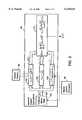
- FIG. 1is a schematic block diagram of the overall communications link in accordance with the teachings of the preferred embodiment of the present invention
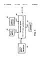
- FIG. 2is a schematic block diagram of the improved antenna nulling system in accordance with the teachings of the preferred embodiment of the present invention
- FIG. 3is a detailed schematic block diagram of the antenna pattern calculator shown in FIG. 2;
- FIG. 4is a detailed schematic block diagram of the sequential update shown in FIG. 2;
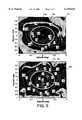
- FIG. 5is a diagram comparing the antenna pattern nulling performance of a prior art nulling algorithm with the performance of the present invention.
- the communication link 10employing the improved nulling antenna system of the present invention is shown.
- the communication link 10is somewhat similar to that shown in U.S. Pat. No. 5,175,558, which is hereby incorporated by reference.
- the communication link 10includes a terrestrial or satellite terminal 12 and a communications satellite 14.
- the terrestrial terminal 12includes a convolutional encoder 16, a pseudo-random interleaver 18, and a spread spectrum modulator 20.
- Digital voice and data 22 to be transmittedis processed by the convolutional encoder 16.
- digital voice and data 22may comprise signals transmitted by the terminal 12 in the microwave frequency range or any other appropriate frequency range.
- the convolutional encoder 16introduces known redundancy among symbols or bits within a few constraint length spacings.
- the pseudo-random interleaver 18spreads the related symbols or bits much farther apart pseudo-randomly.
- the spread spectrum modulator 20spreads the data over a channel bandwidth many times greater than the data bandwidth. This results in a spreading of the jammer power across the channel bandwidth, effectively reducing the noise density.
- a spread spectrum demodulator 24can despread the data channel back into the data bandwidth. This modulation/demodulation operation results in a significant signal-to-noise ratio improvement.
- the coded signals 26are transmitted and eventually received by an area coverage adaptive antenna nulling system 28 in the communications satellite 14.
- the antenna nulling system 28may also receive other signals such as thermal and switching noise 30 and may be subject to jamming signals 32 that can comprise wide band, pulse or partial band jamming.
- the task of the antenna nulling system 28is to combine the correlated signals at a beamformer in such a way as to null the jamming signal, effectively removing it from the antenna nulling system output 34.
- a performance feedback 36is fedback to the antenna nulling system 28 to allow correlation measurements for the adaptive process and assure that everything is time aligned.
- a pseudo-random deinterleaver 38restores the spacing and sequence of the coded symbols or bits which were previously interleaved. In this regard, any remaining jammer bursts are now spread pseudo-randomly so that they appear as random errors within the convolutional decoder constraint length.
- Jammer state or side information (erasures) 40is transmitted from the spread spectrum demodulator 24 to the pseudo-random deinterleaver 38 for the purpose of identifying those symbols or bits which have been jammed and are not considered reliable.
- a soft decision Viterbi decoder 42will use the reliability information to optimally correct errors and erasures.
- the resulting digital voice and data signal 44is subsequently available, relatively free of jamming interference, with a substantially reduced probability of bit error (BER).
- BERbit error
- This systemmay also be implemented without the benefit of jammer state information, with minor degradations in performance.
- hard decision Viterbi decodingmay be substituted for soft decision decoding.
- the coded transmitted signal 26is received by a multibeam antenna 48 which may comprise a conventional multibeam antenna consisting of a dish or other reflective element which forms an image of the source on an array of antenna elements or feedhorns 50 laid out in a particular pattern.
- the feedhorns 50are fed by a feed array 52 consisting of parallel paths of waveguides which are directed along parallel path 54 by means of directional couplers to a switch tree 56.
- a feed array 52consisting of parallel paths of waveguides which are directed along parallel path 54 by means of directional couplers to a switch tree 56.
- nulling jamming signalsis to determine how much of a jamming signal is present in each of the individual antenna elements 50 or paths of the feed array 52 and canceling, by appropriate gain weighting and phasing of the jamming signal.
- the resultis that at a specific angle that the jamming signal happens to be at relative to the antenna 48, the antenna 48 produces the corrective amplitude and phase of the various antenna elements 50 or feed array paths with the proper weight set in a beamformer so that the jamming signal can't get through to the output at that angle.
- the gain weightingis performed based upon the overall antenna pattern, further discussed herein, as opposed to simply adjusting the weights based upon monitoring the existing weights at the beamformer as is performed in U.S. Pat. No. 5,175,558.
- the switch tree 56is essentially a multiplexed switch that switches between paths 54 of the feed array 52 such that only sample signals received from a single element or horn 50 is dealt with separately at a given time along the feed or sample path 58.
- the switch tree outputis fed to a mixer 60 which mixes this single feed with a local oscillator 62 to shift the frequency from an RF signal to an IF signal, as well as despread the signal. It should be noted that the despreading is accomplished by having the local oscillator 62 providing only the same frequency shifts that are used in the spread spectrum code used by the spread spectrum modulator 20 and the spread spectrum demodulator 24.
- the local oscillator 62is not a constant frequency but is either a frequency hopped replica of the original frequency hopping code, or it is a pseudo-noise (PN) modulated local oscillator using the same PN code as would have been used in the direct sequence modulation for the desired signal.
- the band pass filter 64attenuates frequencies in the original data communication band. Therefore, the band pass filter 64 eliminates the desired signal from this feed path 58 so that the output 66 is everything that corresponds to unknown signals, such as jammer signals or noise. In other words, the band pass filter 64 strips off all the user communication signals and only leaves the jammer signals or noise associated with that particular antenna element 50 of the feed array 52.
- the switch tree 56may be eliminated should multiple parallel hardware paths 58 be used.
- the calibration phase shift 68is a phase shifter used to control the phase error or phase bias along the feed path 58 so that for a zero phase, a zero phase measurement results. Accordingly, the calibration phase shift 68 is a control for a calibration procedure. With the calibration phase shift 68 being similar to the components used in the beamformer 70, the calibration phase shift 68 also has similar temperature drift characteristics and may therefore, also compensate the correlation loop or feed path 58 against phase errors due to temperature changes. The output from the calibration phase shift 68 is applied to a correlator 72, further discussed herein.
- the beamformer 70is a well known apparatus that controls the complex gain (i.e., magnitude and phase) of the individual paths 54 by combining coherently the signals from all of the various paths.
- the beamformer 70performs an inner product between the vector of the voltages at the input to the beamformer 70 and the weight vector received by a weight controller 74.
- the beamformer 70essentially weights each antenna element 50 of the feed array 52 and sums this with the signals received from the antenna 48 to form a single composite beam output or signal 76.
- This composite output 76is applied to the spread spectrum demodulator 24, pseudo-random deinterleaver 38 and decoder 42 along path 78.
- a composite or sum feedback path 80is also routed from the output 76.
- output 76 of the beamformer 70should represent the communication signals without any jamming signals present.
- the composite signal from composite feedback path 80is applied to a mixer 82 which mixes this composite signal with a local oscillator 84.
- the local oscillator 84is again adjusted in frequency such that the output from the mixer 82 is the desired IF signal similar to the local oscillator 62 and mixer 60.
- a band pass filter (BPF) 86strips off everything from this IF signal so that the output 88 from the band pass filter 86 is everything that corresponds to unknown signals.
- the output of the band pass filter 86are all the signals which do not synchronize with the frequency hopping code and therefore might represent interference, undesired jamming or noise signals.
- This output 88is also applied to the correlator 72.
- the correlator 72performs two functions. First, the correlator 72 takes the two input signals (one from the calibration phase shift 68 (sample signal) and one from the band pass filter 86 (composite signal)) and multiplies these inputs together to provide a cross-correlation ⁇ i (n) between the sample path 58 and the sum path 80. This correlation essentially identifies what is common between the two paths and this information is used to null the jamming signals by minimizing output jammer power using the gradient approach. Secondly, the correlator 72 measures the auto-correlation or power of the sample path 58 which information is passed to the adaptive step-size block 92. The sequential update unit 90, further shown in detail in FIG.
- the sequential update 90sequentially calculates a new complex weight w i (n+1) for each antenna element 50 and forwards the new weights to the weight memory 96.
- the ⁇ i (n) function from the antenna pattern calculation block 94tries to keep the current antenna pattern as close to the quiescent antenna pattern as possible, while the ⁇ i (n) function from the correlator 72 wants to null the jamming signal.
- the sequential update unit 90balances these two inputs or interests to null the jamming signal, as well as maintain appropriate communications with the users in the theater of interest.
- the new weight memory provided by the sequential update 90is stored in the weight memory 96 and subsequently used by the weight controller 74 to control the weighting in the beamformer 70.
- the antenna pattern calculation block 94measures the difference in pattern magnitude and phase between the adapted antenna pattern (y A ( ⁇ , ⁇ , w)) and the quiescent antenna pattern (y Q ( ⁇ , ⁇ )) of the multibeam antenna 48.
- the adapted antenna patternis the pattern obtained from the current weighting of the feed array 52, via the beamformer 70.
- the quiescent antenna patternis the original pattern used to cover the particular theater of interest.
- the adaptive step-size 92weights the ⁇ i (n) and ⁇ i (n) functions to control the incremental steps that the current weights will be changed by, similar to that used in U.S. Pat. No. 5,175,558.
- the weight memory 96stores all of the weights for each antenna element 50 in the feed array 52 and provides this information to the antenna pattern calculation block 94 and the sequential update block 90 for subsequent use in determining new weight settings for each antenna element 50.
- a master control processor 98is connected to all of the main components of the antenna nulling system 28. Depending on the type of hardware implementation, the master controller processor 98 may perform some or all the functions of these components. In the preferred embodiment, the master controller processor 98 comprises a pipeline processor consisting of multiple instruction, multiple data (MIMD) architecture.
- MIMDmultiple instruction, multiple data
- the antenna pattern calculation block 94receives the current adapted weight information from the weight memory 96 for each of the antenna elements 50.
- the control and calculation of the antenna pattern calculation block 94are performed, via the master control processor 98.
- the antenna pattern calculation block 94includes antenna model data x m 's 100 which is feed model data.
- the antenna model or feed model data 100models the output magnitude and phase of each of the antenna elements 50 along path 54 if a signal is in the Mth position or point. This data is passed along parallel paths 102 and fed to an adapted antenna pattern block 104, a quiescent antenna pattern block 106, and a feed model selector block 108.
- the adapted antenna pattern block 104calculates the adaptive antenna pattern at the Mth direction or point for all M's.
- the output y A ,m (n)'s from the adaptive antenna pattern block 104is the adapted pattern at a point m at time n.
- block 104determines the adapted pattern for each of the points m at a time n.
- the quiescent antenna pattern block 106performs a similar function as the adapted antenna pattern block 104, except that each x is multiplied by the quiescent weights ⁇ versus the current weights w(n), as with adapted antenna pattern block 104.
- the output y a ,m 's from quiescent antenna pattern block 106is the quiescent antenna pattern at points m.
- the feed model selector block 108determines and controls which weights are being determining for which given antenna element 50. This block 108 provides an output of x i ,m 's.
- the master control processor 98controls which i or antenna element 50 you are looking at and informs the antenna model data block 100 as to which antenna element 50 you are at.
- the master control processor 98also determines the number of m points to be used for the calculation.
- a difference in pattern magnitude ⁇ i (n) 110is calculated, further discussed herein.
- This approachis an improvement over the difference between weights approach because it provides for sharper nulling, thereby providing increased percent coverage area (PCA) to receive communication signals from more users while effectively nulling the jamming signals.
- PCApercent coverage area
- the sequential update 90receives the correlation information ⁇ i (n) from the correlator 72, the difference in pattern magnitude information ⁇ i (n) from the antenna pattern calculation block 94, the current weight memory w i (n) from the weight memory 96 and the adaptive step-size ⁇ i (n) from the adaptive step-size 92 to update the current weights w i (n) with the new weights w i (n+1).
- the sequential update 90balances the input from the correlator 92 and the input from the antenna pattern calculation block 94 to null the jammer signal while also maintaining as large as antenna pattern coverage area as possible.
- the weight update equation shown in sequential update block 90is derived as follows.
- the first part of this cost function, w H ⁇ n w,is the portion that reduces jammer interference using the gradient approach.
- the second portionattempts to preserve the quiescent pattern by making the two patterns as close together as possible over the coverage area using the difference in pattern magnitude approach.
- ⁇ i (n) and ⁇ i (n)are the ith elements of ⁇ i (n) and ⁇ i (n) and represent the outputs of the correlator and antenna model blocks respectively.
- the performance of the improved antenna nulling system 28is shown compared to that of U.S. Pat. No. 5,175,558.
- graph 112shows the performance of U.S. Pat. No. 5,175,558
- graph 114shows the performance of the improved antenna nulling system 28.
- the weight update equation used by the improved antenna nulling system 28produces much tighter nulls which improves the percent coverage area. In this example, a 20% to 40% improvement is shown over the existing system.
- the area 116 in graph 112is the nulled portion in coverage region 118 while the regions 120 are the nulled portions in coverage region 122.
- the weight update equationutilizes both the gradient approach iteratively to readjust the magnitude and the angle of the received signal from each antenna feed to suppress the overall jammer signal strength and a difference pattern magnitude approach to increase gain around the removed jamming signal to increase signal strength to users in the area as clearly observed here.
Landscapes
- Engineering & Computer Science (AREA)
- Radar, Positioning & Navigation (AREA)
- Remote Sensing (AREA)
- Computer Networks & Wireless Communication (AREA)
- Signal Processing (AREA)
- Physics & Mathematics (AREA)
- General Physics & Mathematics (AREA)
- Variable-Direction Aerials And Aerial Arrays (AREA)
- Radio Transmission System (AREA)
Abstract
Description
ε.sup.2 =w.sup.H Φ.sub.n w+k∫∫.sub.106 (|y.sub.A (θ,φ,w)|.sup.p -|y.sub.Q (θ,φ)|.sup.p).sup.2 dΩ (1)
y.sub.A (m,w)=x.sup.T (m)w (5)
y.sub.Q (m)=x.sup.T (m)ξ (6)
w(n+1)=w(n)-μ(γ(n)+β(n)) (17)
w.sub.i (n+1)=w.sub.i (n)-μ.sub.i (γ.sub.i (n)+β.sub.i (n))(18)
Claims (15)
Priority Applications (2)
| Application Number | Priority Date | Filing Date | Title |
|---|---|---|---|
| US09/291,713US6130643A (en) | 1999-04-14 | 1999-04-14 | Antenna nulling system for suppressing jammer signals |
| GB0010160AGB2361825B (en) | 1999-04-14 | 2000-04-27 | Improved antenna nulling system for suppressing jammer signals |
Applications Claiming Priority (2)
| Application Number | Priority Date | Filing Date | Title |
|---|---|---|---|
| US09/291,713US6130643A (en) | 1999-04-14 | 1999-04-14 | Antenna nulling system for suppressing jammer signals |
| GB0010160AGB2361825B (en) | 1999-04-14 | 2000-04-27 | Improved antenna nulling system for suppressing jammer signals |
Publications (1)
| Publication Number | Publication Date |
|---|---|
| US6130643Atrue US6130643A (en) | 2000-10-10 |
Family
ID=26244168
Family Applications (1)
| Application Number | Title | Priority Date | Filing Date |
|---|---|---|---|
| US09/291,713Expired - LifetimeUS6130643A (en) | 1999-04-14 | 1999-04-14 | Antenna nulling system for suppressing jammer signals |
Country Status (2)
| Country | Link |
|---|---|
| US (1) | US6130643A (en) |
| GB (1) | GB2361825B (en) |
Cited By (23)
| Publication number | Priority date | Publication date | Assignee | Title |
|---|---|---|---|---|
| US20020023247A1 (en)* | 2000-08-21 | 2002-02-21 | Toshiyuki Akiyama | System for transmitting information codes with multi-level modulation scheme and a modulation apparatus |
| US20020190900A1 (en)* | 2001-05-11 | 2002-12-19 | Nec Corporation | Adaptive array antenna receiving apparatus capable of shortening convergence time of antenna weight |
| US6590833B1 (en)* | 2002-08-08 | 2003-07-08 | The United States Of America As Represented By The Secretary Of The Navy | Adaptive cross correlator |
| US6603818B1 (en) | 1999-09-23 | 2003-08-05 | Lockheed Martin Energy Research Corporation | Pulse transmission transceiver architecture for low power communications |
| US20030146870A1 (en)* | 2000-08-01 | 2003-08-07 | Guo Yingjie Jay | Apparatus for an methods of receiving a transmission signal |
| US6665286B1 (en)* | 1998-02-13 | 2003-12-16 | Nec Corporation | Adaptive receiving device removing interference from users and multi-paths by antenna directivity control |
| US6668167B2 (en) | 2000-01-26 | 2003-12-23 | Mcdowell Mark | Method and apparatus for sharing mobile user event information between wireless networks and fixed IP networks |
| US6839554B2 (en) | 2000-01-26 | 2005-01-04 | Invertix Corporation | Method and apparatus for sharing mobile user event information between wireless networks and fixed IP networks |
| US20050096090A1 (en)* | 2003-10-30 | 2005-05-05 | Shirish Nagaraj | Method and apparatus for providing user specific downlink beamforming in a fixed beam network |
| US20050151685A1 (en)* | 2002-04-11 | 2005-07-14 | Anders Eneroth | Method for verifying dynamically a multiple beam antenna placed on a vehicle |
| US6931235B2 (en) | 2000-02-29 | 2005-08-16 | Dynamic Telecommunications, Inc. | Method and apparatus for co-channel interference measurements and base station color code decoding for drive tests in TDMA, cellular, and PCS networks |
| US20050228841A1 (en)* | 2004-04-08 | 2005-10-13 | Grobert Paul H | System and method for dynamic weight processing |
| US20070264929A1 (en)* | 2004-12-18 | 2007-11-15 | Chao-Chun Chen | Satellite communication system architecture |
| US20080150794A1 (en)* | 2006-07-26 | 2008-06-26 | Junichiro Suzuki | Weight calculation method, weight calculation device, adaptive array antenna, and radar device |
| US20120128171A1 (en)* | 2001-12-21 | 2012-05-24 | One-E-Way, Inc. | Wireless Digital Audio Music System |
| US20120229336A1 (en)* | 2009-12-03 | 2012-09-13 | Youichi Koichi | Antenna beam directivity apparatus and antenna beam directivity method |
| CN103475394A (en)* | 2013-08-28 | 2013-12-25 | 西安空间无线电技术研究所 | Adaptive interference suppression method for spaceborne phased-array antenna |
| US20140241543A1 (en)* | 2001-12-21 | 2014-08-28 | One-E-Way Inc. | Wireless Digital Audio Music System |
| US20150116141A1 (en)* | 2013-10-28 | 2015-04-30 | Raytheon Company | Adaptive dynamic cluster deinterleaving |
| CN105162528A (en)* | 2015-07-18 | 2015-12-16 | 西安电子科技大学 | Anti-interference method and apparatus based on satellite communication phased-array antenna |
| CN106483536A (en)* | 2015-08-26 | 2017-03-08 | 罗克韦尔柯林斯公司 | Satellite-signal collection using the antenna possessing beamforming capabilities |
| US20170214995A1 (en)* | 2001-12-21 | 2017-07-27 | C. Earl Woolfork | Wireless Digital Audio Music System |
| CN107015206A (en)* | 2017-03-20 | 2017-08-04 | 南京理工大学 | Adaptive antenna interference detection system and method |
Citations (4)
| Publication number | Priority date | Publication date | Assignee | Title |
|---|---|---|---|---|
| US4278978A (en)* | 1979-09-18 | 1981-07-14 | Nasa | Baseband signal combiner for large aperture antenna array |
| US4635063A (en)* | 1983-05-06 | 1987-01-06 | Hughes Aircraft Company | Adaptive antenna |
| US5175558A (en)* | 1992-02-10 | 1992-12-29 | Trw Inc. | Nulling system for constraining pulse jammer duty factors |
| US5493307A (en)* | 1994-05-26 | 1996-02-20 | Nec Corporation | Maximal deversity combining interference cancellation using sub-array processors and respective delay elements |
Family Cites Families (1)
| Publication number | Priority date | Publication date | Assignee | Title |
|---|---|---|---|---|
| US4931977A (en)* | 1987-10-30 | 1990-06-05 | Canadian Marconi Company | Vectorial adaptive filtering apparatus with convergence rate independent of signal parameters |
- 1999
- 1999-04-14USUS09/291,713patent/US6130643A/ennot_activeExpired - Lifetime
- 2000
- 2000-04-27GBGB0010160Apatent/GB2361825B/ennot_activeExpired - Fee Related
Patent Citations (4)
| Publication number | Priority date | Publication date | Assignee | Title |
|---|---|---|---|---|
| US4278978A (en)* | 1979-09-18 | 1981-07-14 | Nasa | Baseband signal combiner for large aperture antenna array |
| US4635063A (en)* | 1983-05-06 | 1987-01-06 | Hughes Aircraft Company | Adaptive antenna |
| US5175558A (en)* | 1992-02-10 | 1992-12-29 | Trw Inc. | Nulling system for constraining pulse jammer duty factors |
| US5493307A (en)* | 1994-05-26 | 1996-02-20 | Nec Corporation | Maximal deversity combining interference cancellation using sub-array processors and respective delay elements |
Cited By (43)
| Publication number | Priority date | Publication date | Assignee | Title |
|---|---|---|---|---|
| US6665286B1 (en)* | 1998-02-13 | 2003-12-16 | Nec Corporation | Adaptive receiving device removing interference from users and multi-paths by antenna directivity control |
| US6625229B2 (en) | 1999-09-23 | 2003-09-23 | Lockheed Martin Energy Research Corporation | Pulse transmission transmitter including a higher order time derivate filter |
| US6603818B1 (en) | 1999-09-23 | 2003-08-05 | Lockheed Martin Energy Research Corporation | Pulse transmission transceiver architecture for low power communications |
| US6606350B2 (en) | 1999-09-23 | 2003-08-12 | Lockheed Martin Energy Research Corporation | Pulse transmission receiver with higher-order time derivative pulse generator |
| US6621878B2 (en)* | 1999-09-23 | 2003-09-16 | Lockheed Martin Energy Research Corporation | Pulse transmission receiver with higher-order time derivative pulse correlator |
| US6839554B2 (en) | 2000-01-26 | 2005-01-04 | Invertix Corporation | Method and apparatus for sharing mobile user event information between wireless networks and fixed IP networks |
| US6668167B2 (en) | 2000-01-26 | 2003-12-23 | Mcdowell Mark | Method and apparatus for sharing mobile user event information between wireless networks and fixed IP networks |
| US6931235B2 (en) | 2000-02-29 | 2005-08-16 | Dynamic Telecommunications, Inc. | Method and apparatus for co-channel interference measurements and base station color code decoding for drive tests in TDMA, cellular, and PCS networks |
| US6894643B2 (en)* | 2000-08-01 | 2005-05-17 | Fujitsu Limited | Apparatus for and methods of receiving a transmission signal |
| US20030146870A1 (en)* | 2000-08-01 | 2003-08-07 | Guo Yingjie Jay | Apparatus for an methods of receiving a transmission signal |
| US20020023247A1 (en)* | 2000-08-21 | 2002-02-21 | Toshiyuki Akiyama | System for transmitting information codes with multi-level modulation scheme and a modulation apparatus |
| US6825808B2 (en)* | 2001-05-11 | 2004-11-30 | Nec Corporation | Adaptive array antenna receiving apparatus capable of shortening convergence time of antenna weight |
| US20020190900A1 (en)* | 2001-05-11 | 2002-12-19 | Nec Corporation | Adaptive array antenna receiving apparatus capable of shortening convergence time of antenna weight |
| US9107000B2 (en)* | 2001-12-21 | 2015-08-11 | One-E-Way, Inc. | Wireless digital audio music system |
| US20140241543A1 (en)* | 2001-12-21 | 2014-08-28 | One-E-Way Inc. | Wireless Digital Audio Music System |
| US10129627B2 (en)* | 2001-12-21 | 2018-11-13 | One-E-Way, Inc. | Wireless digital audio music system |
| US20120128171A1 (en)* | 2001-12-21 | 2012-05-24 | One-E-Way, Inc. | Wireless Digital Audio Music System |
| US20170214995A1 (en)* | 2001-12-21 | 2017-07-27 | C. Earl Woolfork | Wireless Digital Audio Music System |
| US9282396B2 (en)* | 2001-12-21 | 2016-03-08 | One-E-Way Inc. | Wireless digital audio music system |
| US20050151685A1 (en)* | 2002-04-11 | 2005-07-14 | Anders Eneroth | Method for verifying dynamically a multiple beam antenna placed on a vehicle |
| US6992615B2 (en)* | 2002-04-11 | 2006-01-31 | Totalforsvarets Forskningsinstitut | Method for verifying dynamically a multiple beam antenna placed on a vehicle |
| US6590833B1 (en)* | 2002-08-08 | 2003-07-08 | The United States Of America As Represented By The Secretary Of The Navy | Adaptive cross correlator |
| US20060194548A1 (en)* | 2003-10-30 | 2006-08-31 | Shirish Nagaraj | Method and apparatus for providing user specific downlink beamforming in a fixed beam network |
| US7333835B2 (en) | 2003-10-30 | 2008-02-19 | Lucent Technologies Inc. | Method and apparatus for providing user specific downlink beamforming in a fixed beam network |
| US20050096090A1 (en)* | 2003-10-30 | 2005-05-05 | Shirish Nagaraj | Method and apparatus for providing user specific downlink beamforming in a fixed beam network |
| US7054664B2 (en)* | 2003-10-30 | 2006-05-30 | Lucent Technologies Inc. | Method and apparatus for providing user specific downlink beamforming in a fixed beam network |
| US20050228841A1 (en)* | 2004-04-08 | 2005-10-13 | Grobert Paul H | System and method for dynamic weight processing |
| WO2006033667A1 (en)* | 2004-04-08 | 2006-03-30 | Raytheon Company | System and method for dynamic weight processing |
| US8301677B2 (en) | 2004-04-08 | 2012-10-30 | Raytheon Company | System and method for dynamic weight processing |
| US7440988B2 (en) | 2004-04-08 | 2008-10-21 | Raytheon Company | System and method for dynamic weight processing |
| US20090006515A1 (en)* | 2004-04-08 | 2009-01-01 | Grobert Paul H | System and method for dynamic weight processing |
| US20070264929A1 (en)* | 2004-12-18 | 2007-11-15 | Chao-Chun Chen | Satellite communication system architecture |
| US20080150794A1 (en)* | 2006-07-26 | 2008-06-26 | Junichiro Suzuki | Weight calculation method, weight calculation device, adaptive array antenna, and radar device |
| US7535410B2 (en)* | 2006-07-26 | 2009-05-19 | Kabushiki Kaisha Toshiba | Weight calculation method, weight calculation device, adaptive array antenna, and radar device |
| US20120229336A1 (en)* | 2009-12-03 | 2012-09-13 | Youichi Koichi | Antenna beam directivity apparatus and antenna beam directivity method |
| CN103475394A (en)* | 2013-08-28 | 2013-12-25 | 西安空间无线电技术研究所 | Adaptive interference suppression method for spaceborne phased-array antenna |
| US9229095B2 (en)* | 2013-10-28 | 2016-01-05 | Raytheon Company | Adaptive dynamic cluster deinterleaving |
| US20150116141A1 (en)* | 2013-10-28 | 2015-04-30 | Raytheon Company | Adaptive dynamic cluster deinterleaving |
| CN105162528A (en)* | 2015-07-18 | 2015-12-16 | 西安电子科技大学 | Anti-interference method and apparatus based on satellite communication phased-array antenna |
| CN106483536A (en)* | 2015-08-26 | 2017-03-08 | 罗克韦尔柯林斯公司 | Satellite-signal collection using the antenna possessing beamforming capabilities |
| CN106483536B (en)* | 2015-08-26 | 2019-04-02 | 罗克韦尔柯林斯公司 | It is acquired using the satellite-signal for the antenna for having beamforming capabilities |
| CN107015206A (en)* | 2017-03-20 | 2017-08-04 | 南京理工大学 | Adaptive antenna interference detection system and method |
| CN107015206B (en)* | 2017-03-20 | 2020-04-07 | 南京理工大学 | Adaptive antenna interference detection system and method |
Also Published As
| Publication number | Publication date |
|---|---|
| GB2361825B (en) | 2002-06-26 |
| GB0010160D0 (en) | 2000-06-14 |
| GB2361825A (en) | 2001-10-31 |
Similar Documents
| Publication | Publication Date | Title |
|---|---|---|
| US6130643A (en) | Antenna nulling system for suppressing jammer signals | |
| US5175558A (en) | Nulling system for constraining pulse jammer duty factors | |
| US5585803A (en) | Apparatus and method for controlling array antenna comprising a plurality of antenna elements with improved incoming beam tracking | |
| EP1320212B1 (en) | Method and apparatus for frequency multiplexing with interference cancellation | |
| JP2697648B2 (en) | Decision feedback equalizer | |
| US6331837B1 (en) | Spatial interferometry multiplexing in wireless communications | |
| EP0779001B1 (en) | Reception method and base station receiver | |
| US8090339B1 (en) | Off-line channel tuning amplitude slope matched filter architecture | |
| CA2227522C (en) | Self-calibration apparatus and method for communication device | |
| JP2005527789A (en) | Subband beamforming system and method using adaptive weighted normalization | |
| KR0145982B1 (en) | Path gain estimation in a receiver | |
| JP2002094318A (en) | Signal extraction method and apparatus in wireless communication system | |
| JPH0661893A (en) | Interference wave elimination device | |
| KR20060127078A (en) | Adaptive Control Adjustment Method of Adaptive Interference Canceller | |
| RU2177207C2 (en) | Receiver of mobile communication system and method of reception in mobile communication system | |
| JP4169884B2 (en) | Communication device using adaptive antenna | |
| EP1267497B1 (en) | Multiuser interference cancellation apparatus | |
| US6233272B1 (en) | Spread spectrum communication receiver | |
| US7031415B2 (en) | Bi-modular adaptive CDMA receiver | |
| USH739H (en) | Auxiliary antenna interference canceller | |
| JP4061580B2 (en) | Beam forming method for receiving array antenna | |
| Poberezhskiy | Diversity schemes and coherent combining in digital receivers | |
| JP3096733B2 (en) | Array antenna beam forming method | |
| JP4507102B2 (en) | GPS interference canceller | |
| Najar et al. | High resolution adaptive arrays based on random processing techniques: frequency hopping modulation |
Legal Events
| Date | Code | Title | Description |
|---|---|---|---|
| AS | Assignment | Owner name:TRW INC., CALIFORNIA Free format text:ASSIGNMENT OF ASSIGNORS INTEREST;ASSIGNORS:TRIPPETT, JOHN M.;VAUGHAN, ROBERT E.;REEL/FRAME:009906/0046;SIGNING DATES FROM 19990409 TO 19990414 | |
| STCF | Information on status: patent grant | Free format text:PATENTED CASE | |
| AS | Assignment | Owner name:NORTHROP GRUMMAN CORPORATION, CALIFORNIA Free format text:ASSIGNMENT OF ASSIGNORS INTEREST;ASSIGNOR:TRW, INC. N/K/A NORTHROP GRUMMAN SPACE AND MISSION SYSTEMS CORPORATION, AN OHIO CORPORATION;REEL/FRAME:013751/0849 Effective date:20030122 Owner name:NORTHROP GRUMMAN CORPORATION,CALIFORNIA Free format text:ASSIGNMENT OF ASSIGNORS INTEREST;ASSIGNOR:TRW, INC. N/K/A NORTHROP GRUMMAN SPACE AND MISSION SYSTEMS CORPORATION, AN OHIO CORPORATION;REEL/FRAME:013751/0849 Effective date:20030122 | |
| FEPP | Fee payment procedure | Free format text:PAYOR NUMBER ASSIGNED (ORIGINAL EVENT CODE: ASPN); ENTITY STATUS OF PATENT OWNER: LARGE ENTITY | |
| FPAY | Fee payment | Year of fee payment:4 | |
| FEPP | Fee payment procedure | Free format text:PAYER NUMBER DE-ASSIGNED (ORIGINAL EVENT CODE: RMPN); ENTITY STATUS OF PATENT OWNER: LARGE ENTITY | |
| FPAY | Fee payment | Year of fee payment:8 | |
| AS | Assignment | Owner name:NORTHROP GRUMMAN SPACE & MISSION SYSTEMS CORP.,CAL Free format text:ASSIGNMENT OF ASSIGNORS INTEREST;ASSIGNOR:NORTHROP GRUMMAN CORPORTION;REEL/FRAME:023699/0551 Effective date:20091125 Owner name:NORTHROP GRUMMAN SPACE & MISSION SYSTEMS CORP., CA Free format text:ASSIGNMENT OF ASSIGNORS INTEREST;ASSIGNOR:NORTHROP GRUMMAN CORPORTION;REEL/FRAME:023699/0551 Effective date:20091125 | |
| AS | Assignment | Owner name:NORTHROP GRUMMAN SYSTEMS CORPORATION,CALIFORNIA Free format text:ASSIGNMENT OF ASSIGNORS INTEREST;ASSIGNOR:NORTHROP GRUMMAN SPACE & MISSION SYSTEMS CORP.;REEL/FRAME:023915/0446 Effective date:20091210 Owner name:NORTHROP GRUMMAN SYSTEMS CORPORATION, CALIFORNIA Free format text:ASSIGNMENT OF ASSIGNORS INTEREST;ASSIGNOR:NORTHROP GRUMMAN SPACE & MISSION SYSTEMS CORP.;REEL/FRAME:023915/0446 Effective date:20091210 | |
| FPAY | Fee payment | Year of fee payment:12 |