US6129764A - Modular prosthetic joint components - Google Patents
Modular prosthetic joint componentsDownload PDFInfo
- Publication number
- US6129764A US6129764AUS09/199,148US19914898AUS6129764AUS 6129764 AUS6129764 AUS 6129764AUS 19914898 AUS19914898 AUS 19914898AUS 6129764 AUS6129764 AUS 6129764A
- Authority
- US
- United States
- Prior art keywords
- component
- slot
- head
- trunnion
- bore
- Prior art date
- Legal status (The legal status is an assumption and is not a legal conclusion. Google has not performed a legal analysis and makes no representation as to the accuracy of the status listed.)
- Expired - Lifetime
Links
- 210000004095humeral headAnatomy0.000claimsabstractdescription30
- 210000000323shoulder jointAnatomy0.000claimsdescription12
- 238000000034methodMethods0.000claims5
- 238000003780insertionMethods0.000claims1
- 230000037431insertionEffects0.000claims1
- 210000004394hip jointAnatomy0.000abstractdescription4
- 125000006850spacer groupChemical group0.000description8
- 210000002758humerusAnatomy0.000description5
- 241001653121GlenoidesSpecies0.000description3
- 210000001503jointAnatomy0.000description3
- 210000000988bone and boneAnatomy0.000description2
- 239000004568cementSubstances0.000description1
- 238000000576coating methodMethods0.000description1
- 238000012986modificationMethods0.000description1
- 230000004048modificationEffects0.000description1
Images


Classifications
- A—HUMAN NECESSITIES
- A61—MEDICAL OR VETERINARY SCIENCE; HYGIENE
- A61F—FILTERS IMPLANTABLE INTO BLOOD VESSELS; PROSTHESES; DEVICES PROVIDING PATENCY TO, OR PREVENTING COLLAPSING OF, TUBULAR STRUCTURES OF THE BODY, e.g. STENTS; ORTHOPAEDIC, NURSING OR CONTRACEPTIVE DEVICES; FOMENTATION; TREATMENT OR PROTECTION OF EYES OR EARS; BANDAGES, DRESSINGS OR ABSORBENT PADS; FIRST-AID KITS
- A61F2/00—Filters implantable into blood vessels; Prostheses, i.e. artificial substitutes or replacements for parts of the body; Appliances for connecting them with the body; Devices providing patency to, or preventing collapsing of, tubular structures of the body, e.g. stents
- A61F2/02—Prostheses implantable into the body
- A61F2/30—Joints
- A61F2/40—Joints for shoulders
- A61F2/4014—Humeral heads or necks; Connections of endoprosthetic heads or necks to endoprosthetic humeral shafts
- A—HUMAN NECESSITIES
- A61—MEDICAL OR VETERINARY SCIENCE; HYGIENE
- A61F—FILTERS IMPLANTABLE INTO BLOOD VESSELS; PROSTHESES; DEVICES PROVIDING PATENCY TO, OR PREVENTING COLLAPSING OF, TUBULAR STRUCTURES OF THE BODY, e.g. STENTS; ORTHOPAEDIC, NURSING OR CONTRACEPTIVE DEVICES; FOMENTATION; TREATMENT OR PROTECTION OF EYES OR EARS; BANDAGES, DRESSINGS OR ABSORBENT PADS; FIRST-AID KITS
- A61F2/00—Filters implantable into blood vessels; Prostheses, i.e. artificial substitutes or replacements for parts of the body; Appliances for connecting them with the body; Devices providing patency to, or preventing collapsing of, tubular structures of the body, e.g. stents
- A61F2/02—Prostheses implantable into the body
- A61F2/30—Joints
- A61F2/40—Joints for shoulders
- A61F2/4059—Humeral shafts
- A—HUMAN NECESSITIES
- A61—MEDICAL OR VETERINARY SCIENCE; HYGIENE
- A61F—FILTERS IMPLANTABLE INTO BLOOD VESSELS; PROSTHESES; DEVICES PROVIDING PATENCY TO, OR PREVENTING COLLAPSING OF, TUBULAR STRUCTURES OF THE BODY, e.g. STENTS; ORTHOPAEDIC, NURSING OR CONTRACEPTIVE DEVICES; FOMENTATION; TREATMENT OR PROTECTION OF EYES OR EARS; BANDAGES, DRESSINGS OR ABSORBENT PADS; FIRST-AID KITS
- A61F2/00—Filters implantable into blood vessels; Prostheses, i.e. artificial substitutes or replacements for parts of the body; Appliances for connecting them with the body; Devices providing patency to, or preventing collapsing of, tubular structures of the body, e.g. stents
- A61F2/02—Prostheses implantable into the body
- A61F2/30—Joints
- A61F2002/30001—Additional features of subject-matter classified in A61F2/28, A61F2/30 and subgroups thereof
- A61F2002/30108—Shapes
- A61F2002/3011—Cross-sections or two-dimensional shapes
- A61F2002/30138—Convex polygonal shapes
- A61F2002/30154—Convex polygonal shapes square
- A—HUMAN NECESSITIES
- A61—MEDICAL OR VETERINARY SCIENCE; HYGIENE
- A61F—FILTERS IMPLANTABLE INTO BLOOD VESSELS; PROSTHESES; DEVICES PROVIDING PATENCY TO, OR PREVENTING COLLAPSING OF, TUBULAR STRUCTURES OF THE BODY, e.g. STENTS; ORTHOPAEDIC, NURSING OR CONTRACEPTIVE DEVICES; FOMENTATION; TREATMENT OR PROTECTION OF EYES OR EARS; BANDAGES, DRESSINGS OR ABSORBENT PADS; FIRST-AID KITS
- A61F2/00—Filters implantable into blood vessels; Prostheses, i.e. artificial substitutes or replacements for parts of the body; Appliances for connecting them with the body; Devices providing patency to, or preventing collapsing of, tubular structures of the body, e.g. stents
- A61F2/02—Prostheses implantable into the body
- A61F2/30—Joints
- A61F2002/30001—Additional features of subject-matter classified in A61F2/28, A61F2/30 and subgroups thereof
- A61F2002/30108—Shapes
- A61F2002/30199—Three-dimensional shapes
- A61F2002/30224—Three-dimensional shapes cylindrical
- A61F2002/3023—Three-dimensional shapes cylindrical wedge-shaped cylinders
- A—HUMAN NECESSITIES
- A61—MEDICAL OR VETERINARY SCIENCE; HYGIENE
- A61F—FILTERS IMPLANTABLE INTO BLOOD VESSELS; PROSTHESES; DEVICES PROVIDING PATENCY TO, OR PREVENTING COLLAPSING OF, TUBULAR STRUCTURES OF THE BODY, e.g. STENTS; ORTHOPAEDIC, NURSING OR CONTRACEPTIVE DEVICES; FOMENTATION; TREATMENT OR PROTECTION OF EYES OR EARS; BANDAGES, DRESSINGS OR ABSORBENT PADS; FIRST-AID KITS
- A61F2/00—Filters implantable into blood vessels; Prostheses, i.e. artificial substitutes or replacements for parts of the body; Appliances for connecting them with the body; Devices providing patency to, or preventing collapsing of, tubular structures of the body, e.g. stents
- A61F2/02—Prostheses implantable into the body
- A61F2/30—Joints
- A61F2002/30001—Additional features of subject-matter classified in A61F2/28, A61F2/30 and subgroups thereof
- A61F2002/30316—The prosthesis having different structural features at different locations within the same prosthesis; Connections between prosthetic parts; Special structural features of bone or joint prostheses not otherwise provided for
- A61F2002/30329—Connections or couplings between prosthetic parts, e.g. between modular parts; Connecting elements
- A61F2002/30331—Connections or couplings between prosthetic parts, e.g. between modular parts; Connecting elements made by longitudinally pushing a protrusion into a complementarily-shaped recess, e.g. held by friction fit
- A61F2002/30332—Conically- or frustoconically-shaped protrusion and recess
- A61F2002/30339—Double cones, i.e. connecting element having two conical connections, one at each of its opposite ends
- A—HUMAN NECESSITIES
- A61—MEDICAL OR VETERINARY SCIENCE; HYGIENE
- A61F—FILTERS IMPLANTABLE INTO BLOOD VESSELS; PROSTHESES; DEVICES PROVIDING PATENCY TO, OR PREVENTING COLLAPSING OF, TUBULAR STRUCTURES OF THE BODY, e.g. STENTS; ORTHOPAEDIC, NURSING OR CONTRACEPTIVE DEVICES; FOMENTATION; TREATMENT OR PROTECTION OF EYES OR EARS; BANDAGES, DRESSINGS OR ABSORBENT PADS; FIRST-AID KITS
- A61F2/00—Filters implantable into blood vessels; Prostheses, i.e. artificial substitutes or replacements for parts of the body; Appliances for connecting them with the body; Devices providing patency to, or preventing collapsing of, tubular structures of the body, e.g. stents
- A61F2/02—Prostheses implantable into the body
- A61F2/30—Joints
- A61F2002/30001—Additional features of subject-matter classified in A61F2/28, A61F2/30 and subgroups thereof
- A61F2002/30316—The prosthesis having different structural features at different locations within the same prosthesis; Connections between prosthetic parts; Special structural features of bone or joint prostheses not otherwise provided for
- A61F2002/30329—Connections or couplings between prosthetic parts, e.g. between modular parts; Connecting elements
- A61F2002/30383—Connections or couplings between prosthetic parts, e.g. between modular parts; Connecting elements made by laterally inserting a protrusion, e.g. a rib into a complementarily-shaped groove
- A—HUMAN NECESSITIES
- A61—MEDICAL OR VETERINARY SCIENCE; HYGIENE
- A61F—FILTERS IMPLANTABLE INTO BLOOD VESSELS; PROSTHESES; DEVICES PROVIDING PATENCY TO, OR PREVENTING COLLAPSING OF, TUBULAR STRUCTURES OF THE BODY, e.g. STENTS; ORTHOPAEDIC, NURSING OR CONTRACEPTIVE DEVICES; FOMENTATION; TREATMENT OR PROTECTION OF EYES OR EARS; BANDAGES, DRESSINGS OR ABSORBENT PADS; FIRST-AID KITS
- A61F2/00—Filters implantable into blood vessels; Prostheses, i.e. artificial substitutes or replacements for parts of the body; Appliances for connecting them with the body; Devices providing patency to, or preventing collapsing of, tubular structures of the body, e.g. stents
- A61F2/02—Prostheses implantable into the body
- A61F2/30—Joints
- A61F2002/30001—Additional features of subject-matter classified in A61F2/28, A61F2/30 and subgroups thereof
- A61F2002/30316—The prosthesis having different structural features at different locations within the same prosthesis; Connections between prosthetic parts; Special structural features of bone or joint prostheses not otherwise provided for
- A61F2002/30535—Special structural features of bone or joint prostheses not otherwise provided for
- A61F2002/30537—Special structural features of bone or joint prostheses not otherwise provided for adjustable
- A61F2002/30538—Special structural features of bone or joint prostheses not otherwise provided for adjustable for adjusting angular orientation
- A61F2002/3054—Special structural features of bone or joint prostheses not otherwise provided for adjustable for adjusting angular orientation about a connection axis or implantation axis for selecting any one of a plurality of radial orientations between two modular parts, e.g. Morse taper connections, at discrete positions, angular positions or continuous positions
- A—HUMAN NECESSITIES
- A61—MEDICAL OR VETERINARY SCIENCE; HYGIENE
- A61F—FILTERS IMPLANTABLE INTO BLOOD VESSELS; PROSTHESES; DEVICES PROVIDING PATENCY TO, OR PREVENTING COLLAPSING OF, TUBULAR STRUCTURES OF THE BODY, e.g. STENTS; ORTHOPAEDIC, NURSING OR CONTRACEPTIVE DEVICES; FOMENTATION; TREATMENT OR PROTECTION OF EYES OR EARS; BANDAGES, DRESSINGS OR ABSORBENT PADS; FIRST-AID KITS
- A61F2/00—Filters implantable into blood vessels; Prostheses, i.e. artificial substitutes or replacements for parts of the body; Appliances for connecting them with the body; Devices providing patency to, or preventing collapsing of, tubular structures of the body, e.g. stents
- A61F2/02—Prostheses implantable into the body
- A61F2/30—Joints
- A61F2002/30001—Additional features of subject-matter classified in A61F2/28, A61F2/30 and subgroups thereof
- A61F2002/30316—The prosthesis having different structural features at different locations within the same prosthesis; Connections between prosthetic parts; Special structural features of bone or joint prostheses not otherwise provided for
- A61F2002/30535—Special structural features of bone or joint prostheses not otherwise provided for
- A61F2002/30537—Special structural features of bone or joint prostheses not otherwise provided for adjustable
- A61F2002/3055—Special structural features of bone or joint prostheses not otherwise provided for adjustable for adjusting length
- A—HUMAN NECESSITIES
- A61—MEDICAL OR VETERINARY SCIENCE; HYGIENE
- A61F—FILTERS IMPLANTABLE INTO BLOOD VESSELS; PROSTHESES; DEVICES PROVIDING PATENCY TO, OR PREVENTING COLLAPSING OF, TUBULAR STRUCTURES OF THE BODY, e.g. STENTS; ORTHOPAEDIC, NURSING OR CONTRACEPTIVE DEVICES; FOMENTATION; TREATMENT OR PROTECTION OF EYES OR EARS; BANDAGES, DRESSINGS OR ABSORBENT PADS; FIRST-AID KITS
- A61F2/00—Filters implantable into blood vessels; Prostheses, i.e. artificial substitutes or replacements for parts of the body; Appliances for connecting them with the body; Devices providing patency to, or preventing collapsing of, tubular structures of the body, e.g. stents
- A61F2/02—Prostheses implantable into the body
- A61F2/30—Joints
- A61F2002/30001—Additional features of subject-matter classified in A61F2/28, A61F2/30 and subgroups thereof
- A61F2002/30316—The prosthesis having different structural features at different locations within the same prosthesis; Connections between prosthetic parts; Special structural features of bone or joint prostheses not otherwise provided for
- A61F2002/30535—Special structural features of bone or joint prostheses not otherwise provided for
- A61F2002/30537—Special structural features of bone or joint prostheses not otherwise provided for adjustable
- A61F2002/30553—Special structural features of bone or joint prostheses not otherwise provided for adjustable for adjusting a position by translation along an axis
- A—HUMAN NECESSITIES
- A61—MEDICAL OR VETERINARY SCIENCE; HYGIENE
- A61F—FILTERS IMPLANTABLE INTO BLOOD VESSELS; PROSTHESES; DEVICES PROVIDING PATENCY TO, OR PREVENTING COLLAPSING OF, TUBULAR STRUCTURES OF THE BODY, e.g. STENTS; ORTHOPAEDIC, NURSING OR CONTRACEPTIVE DEVICES; FOMENTATION; TREATMENT OR PROTECTION OF EYES OR EARS; BANDAGES, DRESSINGS OR ABSORBENT PADS; FIRST-AID KITS
- A61F2/00—Filters implantable into blood vessels; Prostheses, i.e. artificial substitutes or replacements for parts of the body; Appliances for connecting them with the body; Devices providing patency to, or preventing collapsing of, tubular structures of the body, e.g. stents
- A61F2/02—Prostheses implantable into the body
- A61F2/30—Joints
- A61F2002/30001—Additional features of subject-matter classified in A61F2/28, A61F2/30 and subgroups thereof
- A61F2002/30316—The prosthesis having different structural features at different locations within the same prosthesis; Connections between prosthetic parts; Special structural features of bone or joint prostheses not otherwise provided for
- A61F2002/30535—Special structural features of bone or joint prostheses not otherwise provided for
- A61F2002/30604—Special structural features of bone or joint prostheses not otherwise provided for modular
- A61F2002/30616—Sets comprising a plurality of prosthetic parts of different sizes or orientations
- A—HUMAN NECESSITIES
- A61—MEDICAL OR VETERINARY SCIENCE; HYGIENE
- A61F—FILTERS IMPLANTABLE INTO BLOOD VESSELS; PROSTHESES; DEVICES PROVIDING PATENCY TO, OR PREVENTING COLLAPSING OF, TUBULAR STRUCTURES OF THE BODY, e.g. STENTS; ORTHOPAEDIC, NURSING OR CONTRACEPTIVE DEVICES; FOMENTATION; TREATMENT OR PROTECTION OF EYES OR EARS; BANDAGES, DRESSINGS OR ABSORBENT PADS; FIRST-AID KITS
- A61F2/00—Filters implantable into blood vessels; Prostheses, i.e. artificial substitutes or replacements for parts of the body; Appliances for connecting them with the body; Devices providing patency to, or preventing collapsing of, tubular structures of the body, e.g. stents
- A61F2/02—Prostheses implantable into the body
- A61F2/30—Joints
- A61F2/40—Joints for shoulders
- A61F2/4014—Humeral heads or necks; Connections of endoprosthetic heads or necks to endoprosthetic humeral shafts
- A61F2002/4018—Heads or epiphyseal parts of humerus
- A—HUMAN NECESSITIES
- A61—MEDICAL OR VETERINARY SCIENCE; HYGIENE
- A61F—FILTERS IMPLANTABLE INTO BLOOD VESSELS; PROSTHESES; DEVICES PROVIDING PATENCY TO, OR PREVENTING COLLAPSING OF, TUBULAR STRUCTURES OF THE BODY, e.g. STENTS; ORTHOPAEDIC, NURSING OR CONTRACEPTIVE DEVICES; FOMENTATION; TREATMENT OR PROTECTION OF EYES OR EARS; BANDAGES, DRESSINGS OR ABSORBENT PADS; FIRST-AID KITS
- A61F2/00—Filters implantable into blood vessels; Prostheses, i.e. artificial substitutes or replacements for parts of the body; Appliances for connecting them with the body; Devices providing patency to, or preventing collapsing of, tubular structures of the body, e.g. stents
- A61F2/02—Prostheses implantable into the body
- A61F2/30—Joints
- A61F2/40—Joints for shoulders
- A61F2/4014—Humeral heads or necks; Connections of endoprosthetic heads or necks to endoprosthetic humeral shafts
- A61F2002/4029—Necks
- A—HUMAN NECESSITIES
- A61—MEDICAL OR VETERINARY SCIENCE; HYGIENE
- A61F—FILTERS IMPLANTABLE INTO BLOOD VESSELS; PROSTHESES; DEVICES PROVIDING PATENCY TO, OR PREVENTING COLLAPSING OF, TUBULAR STRUCTURES OF THE BODY, e.g. STENTS; ORTHOPAEDIC, NURSING OR CONTRACEPTIVE DEVICES; FOMENTATION; TREATMENT OR PROTECTION OF EYES OR EARS; BANDAGES, DRESSINGS OR ABSORBENT PADS; FIRST-AID KITS
- A61F2/00—Filters implantable into blood vessels; Prostheses, i.e. artificial substitutes or replacements for parts of the body; Appliances for connecting them with the body; Devices providing patency to, or preventing collapsing of, tubular structures of the body, e.g. stents
- A61F2/02—Prostheses implantable into the body
- A61F2/30—Joints
- A61F2/40—Joints for shoulders
- A61F2/4014—Humeral heads or necks; Connections of endoprosthetic heads or necks to endoprosthetic humeral shafts
- A61F2002/4037—Connections of heads to necks
- A—HUMAN NECESSITIES
- A61—MEDICAL OR VETERINARY SCIENCE; HYGIENE
- A61F—FILTERS IMPLANTABLE INTO BLOOD VESSELS; PROSTHESES; DEVICES PROVIDING PATENCY TO, OR PREVENTING COLLAPSING OF, TUBULAR STRUCTURES OF THE BODY, e.g. STENTS; ORTHOPAEDIC, NURSING OR CONTRACEPTIVE DEVICES; FOMENTATION; TREATMENT OR PROTECTION OF EYES OR EARS; BANDAGES, DRESSINGS OR ABSORBENT PADS; FIRST-AID KITS
- A61F2220/00—Fixations or connections for prostheses classified in groups A61F2/00 - A61F2/26 or A61F2/82 or A61F9/00 or A61F11/00 or subgroups thereof
- A61F2220/0025—Connections or couplings between prosthetic parts, e.g. between modular parts; Connecting elements
- A61F2220/0033—Connections or couplings between prosthetic parts, e.g. between modular parts; Connecting elements made by longitudinally pushing a protrusion into a complementary-shaped recess, e.g. held by friction fit
- A—HUMAN NECESSITIES
- A61—MEDICAL OR VETERINARY SCIENCE; HYGIENE
- A61F—FILTERS IMPLANTABLE INTO BLOOD VESSELS; PROSTHESES; DEVICES PROVIDING PATENCY TO, OR PREVENTING COLLAPSING OF, TUBULAR STRUCTURES OF THE BODY, e.g. STENTS; ORTHOPAEDIC, NURSING OR CONTRACEPTIVE DEVICES; FOMENTATION; TREATMENT OR PROTECTION OF EYES OR EARS; BANDAGES, DRESSINGS OR ABSORBENT PADS; FIRST-AID KITS
- A61F2230/00—Geometry of prostheses classified in groups A61F2/00 - A61F2/26 or A61F2/82 or A61F9/00 or A61F11/00 or subgroups thereof
- A61F2230/0002—Two-dimensional shapes, e.g. cross-sections
- A61F2230/0017—Angular shapes
- A61F2230/0021—Angular shapes square
- A—HUMAN NECESSITIES
- A61—MEDICAL OR VETERINARY SCIENCE; HYGIENE
- A61F—FILTERS IMPLANTABLE INTO BLOOD VESSELS; PROSTHESES; DEVICES PROVIDING PATENCY TO, OR PREVENTING COLLAPSING OF, TUBULAR STRUCTURES OF THE BODY, e.g. STENTS; ORTHOPAEDIC, NURSING OR CONTRACEPTIVE DEVICES; FOMENTATION; TREATMENT OR PROTECTION OF EYES OR EARS; BANDAGES, DRESSINGS OR ABSORBENT PADS; FIRST-AID KITS
- A61F2230/00—Geometry of prostheses classified in groups A61F2/00 - A61F2/26 or A61F2/82 or A61F9/00 or A61F11/00 or subgroups thereof
- A61F2230/0063—Three-dimensional shapes
- A61F2230/0069—Three-dimensional shapes cylindrical
- A—HUMAN NECESSITIES
- A61—MEDICAL OR VETERINARY SCIENCE; HYGIENE
- A61F—FILTERS IMPLANTABLE INTO BLOOD VESSELS; PROSTHESES; DEVICES PROVIDING PATENCY TO, OR PREVENTING COLLAPSING OF, TUBULAR STRUCTURES OF THE BODY, e.g. STENTS; ORTHOPAEDIC, NURSING OR CONTRACEPTIVE DEVICES; FOMENTATION; TREATMENT OR PROTECTION OF EYES OR EARS; BANDAGES, DRESSINGS OR ABSORBENT PADS; FIRST-AID KITS
- A61F2250/00—Special features of prostheses classified in groups A61F2/00 - A61F2/26 or A61F2/82 or A61F9/00 or A61F11/00 or subgroups thereof
- A61F2250/0004—Special features of prostheses classified in groups A61F2/00 - A61F2/26 or A61F2/82 or A61F9/00 or A61F11/00 or subgroups thereof adjustable
- A61F2250/0008—Special features of prostheses classified in groups A61F2/00 - A61F2/26 or A61F2/82 or A61F9/00 or A61F11/00 or subgroups thereof adjustable for adjusting a position by translation along an axis or two perpendicular axes
Definitions
- the inventionrelates to prostheses for replacement of a portion of a joint such as, for example, the upper portion of the humerus. More particularly, the invention relates to modular components for replacement of a portion of a joint.
- the human shoulder joint(glenohumeral joint) comprises two major components: the glenoid cavity (glenoid) which is part of the arm and the humeral head (humerus) which is part of the torso.
- Prosthetic shouldersalso comprise glenoid and humeral components.
- the classical prosthetic humeral componentis known as the NEER-type and is a one-piece component which is available in many different sizes for replacement of the upper portion of the organic humerus.
- the classical humeral componenthas a stem which is designed to extend downwardly into a cavity formed within the organic humerus and which is secured with cement or with coatings which promote bone ingrowth to secure the stem.
- the stemis provided with a generally hemispherical head portion which is configured to replace the head of the organic humerus.
- One of the disadvantages of the unitary NEER-type humeral componentsis the necessity of maintaining a large inventory of different sizes to accommodate different bone sizes in different patients.
- orientation of the humeral head relative to the stemalso varies from patient to patient.
- various modular humeral componentshave been proposed.
- the prosthesis 10generally includes a stem portion 12, a spacer 14, and an hemispherical cap 16.
- the spacer 14has opposite tapered studs 14a, 14b.
- the stem 12has a tapered bore 12a which is dimensioned to lockingly engage the stud 14b and the cap 16 has a tapered bore 16a which is dimensioned to lockingly engage the stud 14a.
- the bore 16a in the cap 16is also offset from the geometrical center of the hemispherical cap 16 so that the angular orientation of the cap relative to the stud 14a is variable about the axis of the stud 14a.
- a plurality of positioning bores 16bare provided in the cap 16, the bores 16b being arranged in a circle about the bore 16a.
- An index bore 14cis provided in the spacer 14 adjacent to the stud 14a. The angular orientation of the cap 16 relative to the spacer 14 is fixed with the aid of a pin 18 which engages the index bore 14c and one of the positioning bores 16b.
- Blind holes 12b and 14dare provided in the stem 12 and spacer 14 respectively and a second pin 20 is provided to engage these blind holes to lock the angular position of the spacer relative to the stem.
- the stem and spacerare not, however, angularly adjustable.
- the '479 patentdiscloses a kit 30 which includes a plurality of different sized stems 32a, 32b, a plurality of different sized "bodies" 34a, 34b, a plurality of different sized collars 36a, 36b, 36c, and a plurality of different sized head members 38a, 38b, 38c.
- the componentsare mixed and matched to assemble a humeral component which is best suited for a particular patient.
- the kit provided by the '479 patentprovides a similar degree of customization as the modular component described by Tornier.
- the modular prostheses of the prior artare relatively complex and require elaborate assembly steps.
- Yet another object of the inventionis to provide modular prosthetic shoulder components which are easy to assemble.
- Still another object of the inventionis to provide modular prosthetic joint components in general (i.e., not limited to modular shoulder joint components) which realize the aforestated objects set forth relative to modular prosthetic shoulder components.
- the modular components of the present inventioninclude a plurality of different sized humeral heads, each having a spherical outer surface and an interior tapered bore, a frustroconical intermediate head component dimensioned to lockingly mate with the tapered bore of the humeral heads and having a diametrical slot, and a humeral stem trunnion component having a rectilinear peg dimensioned to lockingly engage the diametrical slot in the intermediate head component.
- the componentsare assembled by partially inserting the intermediate head component into the tapered bore of a humeral head, inserting the peg of the trunnion component into the slot of the intermediate head component, and pressing the components together.
- the intermediate head componenttaper locks with the humeral head and force-fit locks onto the peg of the trunnion component.
- the humeral headPrior to pressing the components together, the humeral head is movable relative to the trunnion component in three planes thereby allowing the practitioner to locate the humeral head in the same position as the organic humeral head which is being replaced.
- the components of the inventionmay also provide utility in other prosthetic joints such as prosthetic hip joints.
- the interior tapered bore of the humeral headis preferably located offset from the axis of the head.
- the slot in the intermediate head componentis preferably defined by three walls and extends diametrically through the entire component.
- the peg of the trunnion componentpreferably is formed as an integral part of a humeral stem component.
- the peg of the trunnion componenthas a square cross section and extends from a square base which is attachable to a humeral stem component.
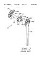
- FIG. 1is an exploded side elevational view in partial section of a modular prosthesis according to the prior art
- FIG. 2is an exploded side elevational view in partial section of a modular prosthesis kit according to the prior art
- FIG. 3is a not-to-scale plan view of the bottom of a humeral head component according to the invention.
- FIG. 4is a not-to-scale sectional view taken along line 4--4 of FIG. 3;
- FIG. 5is a not-to-scale side elevational view of an intermediate had component according to the invention.
- FIG. 6is a not-to-scale bottom plan view of the component of FIG. 5;
- FIG. 7is a not-to-scale top plan view of the component of FIG. 7;
- FIG. 8is a not-to-scale side elevational view of a trunnion component according to the invention.
- FIG. 9is a transparent side elevational view of the components of the invention partially assembled.
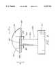
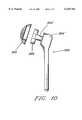
- FIG. 10illustrates a presently preferred embodiment of the invention with the trunnion component being formed as a humeral stem with an integral peg.
- the modular components of the present inventioninclude a plurality of different sized humeral heads 100, each having a spherical outer surface 102 and an interior tapered bore 104, a frustroconical intermediate head component 200 dimensioned to lockingly mate with the tapered bore of the humeral heads 100 and having a diametrical slot 202, and a humeral stem trunnion component 300 having a rectilinear peg 302 dimensioned to lockingly engage the diametrical slot 202 in the intermediate head component 200.
- an exemplary embodiment of a head 100has a surface 102 defined by a surface radius of approximately 0.79 inches.
- the surfaceis not exactly "hemispherical" since it is less than one half of a sphere having a height of approximately 0.58 inches.
- the tapered bore 104is off set from the geometrical center of the surface 102 by approximately 0.118 inches, has a nominal diameter of 0.759 inches plus or minus 0.001 inch, and a taper angle of approximately 2 degrees 51 minutes 28 seconds plus or minus 4 minutes.
- the bore 104has a depth of approximately 0.375 inches.
- the lower edge 103 of the surface 102is provided with a radius edge of approximately 0.06 inches.
- FIGS. 5 and 6An exemplary embodiment of the intermediate component 200 is shown in FIGS. 5 and 6.
- the frustroconical component 200has a maximum diameter of approximately 0.766882 inches and a minimum diameter of approximately 0.752 inches defining a taper angle of approximately 2 degrees 50 minutes 30 seconds plus or minus 3 minutes.
- the diametrical slot 202is aligned with the diameter of the component 200 and is approximately 0.378 plus or minus 0.001 inches wide.
- the overall height of the component 200is approximately 0.300 inches and the slot 202 extends approximately 0.270 inches through the component defining a relatively thin wall top 204 whereby the component may be deformed so as to reduce the width of the slot 202.
- the slotis provided with a pair of stress relieving radiused grooves 206, 208 adjacent the top 204.
- Each groovehas a radius of approximately 0.02 inches.
- FIGS. 7 and 8show an exemplary embodiment of a trunnion component 300 according to the invention.
- the peg 302 of the trunnion component 300is approximately 1.00 inch tall and has an approximately 0.375 plus or minus 0.001 inch square cross section.
- the peg 302extends orthogonally from an approximately 0.5 inch thick and approximately 1.50 inch square base 304.
- a humeral stem component having a recess for receiving the base 304will be provided and the base will be affixed to the stem component.
- the pegis made an integral part of the stem component
- the componentsare assembled by partially inserting the intermediate head component 200 into the tapered bore 102 of a humeral head 100 without forcing the components together.
- the peg 302 of the trunnion component 300is then located in the slot 202 of the intermediate head component 200.
- the head 100is movable relative to the trunnion component 300 in at least four directions, actually in an infinite number of directions.
- the head 100may be rotated about the intermediate component 200 in the direction illustrated by arrows "A"; the head 100 and intermediate component 200 together may be tilted relative to the trunnion component 300 in the direction illustrated by the arrows "B"; the head 100 and intermediate component 200 together may be translated relative to the trunnion component 300 in a direction perpendicular to the page (i.e., back and forth); and the head 100 and the intermediate component 200 can be moved up and down relative to the trunnion component 300.
- Thisallows the practitioner a substantial range of adjustment, i.e., at least four degrees of freedom.
- the intermediate head component 200taper locks with the humeral head 100 and force-fit locks onto the peg 302 of the trunnion component 300.
- FIG. 10illustrates a presently preferred embodiment of the invention wherein the trunnion component 300' is formed as a humeral stem component 304' with an integral peg 302' which is located and dimensioned to couple with components 100 ans 200.
- the intermediate component 200may be rotated from the position shown in FIG. 10 thereby allowing sliding and tilting of intermediate component 200 relative to peg 302'.
Landscapes
- Health & Medical Sciences (AREA)
- Orthopedic Medicine & Surgery (AREA)
- Cardiology (AREA)
- Oral & Maxillofacial Surgery (AREA)
- Transplantation (AREA)
- Engineering & Computer Science (AREA)
- Biomedical Technology (AREA)
- Heart & Thoracic Surgery (AREA)
- Vascular Medicine (AREA)
- Life Sciences & Earth Sciences (AREA)
- Animal Behavior & Ethology (AREA)
- General Health & Medical Sciences (AREA)
- Public Health (AREA)
- Veterinary Medicine (AREA)
- Prostheses (AREA)
Abstract
Description
1. Field of the Invention
The invention relates to prostheses for replacement of a portion of a joint such as, for example, the upper portion of the humerus. More particularly, the invention relates to modular components for replacement of a portion of a joint.
2. State of the Art
For the sake of illustration only and without intending to limit the spirit or scope of the invention, the State of the Art and description of the invention that follows will be set forth in the context of a modular prosthesis for replacing a portion of the human shoulder.
Those skilled in the art will readily be able to apply the teachings set forth herein in the exemplary shoulder context, to provide modular components for the replacement of other joints, such as hip joints, etc.,
The human shoulder joint (glenohumeral joint) comprises two major components: the glenoid cavity (glenoid) which is part of the arm and the humeral head (humerus) which is part of the torso. Prosthetic shoulders also comprise glenoid and humeral components. The classical prosthetic humeral component is known as the NEER-type and is a one-piece component which is available in many different sizes for replacement of the upper portion of the organic humerus.
The classical humeral component has a stem which is designed to extend downwardly into a cavity formed within the organic humerus and which is secured with cement or with coatings which promote bone ingrowth to secure the stem. The stem is provided with a generally hemispherical head portion which is configured to replace the head of the organic humerus.
One of the disadvantages of the unitary NEER-type humeral components is the necessity of maintaining a large inventory of different sizes to accommodate different bone sizes in different patients. In addition to the necessity of providing different sized humeral components, it has been recognized that orientation of the humeral head relative to the stem also varies from patient to patient. For these reasons, various modular humeral components have been proposed.
On type of modular humeral component is described in U.S. Pat. No. 5,358,526 to Tornier. The Tornier prosthesis is shown in prior art FIG. 1.
Referring to FIG. 1, theprosthesis 10 generally includes astem portion 12, a spacer 14, and anhemispherical cap 16. The spacer 14 has oppositetapered studs 14a, 14b.
Thestem 12 has atapered bore 12a which is dimensioned to lockingly engage the stud 14b and thecap 16 has atapered bore 16a which is dimensioned to lockingly engage thestud 14a. Thebore 16a in thecap 16 is also offset from the geometrical center of thehemispherical cap 16 so that the angular orientation of the cap relative to thestud 14a is variable about the axis of thestud 14a.
A plurality of positioning bores 16b are provided in thecap 16, the bores 16b being arranged in a circle about thebore 16a. Anindex bore 14c is provided in the spacer 14 adjacent to thestud 14a. The angular orientation of thecap 16 relative to the spacer 14 is fixed with the aid of apin 18 which engages theindex bore 14c and one of the positioning bores 16b.
Though not specifically taught by Tornier, it is presumed that the three components (stem, spacer, and cap) are provided in a variety of sizes and may be mixed and matched to assemble a humeral component which is best suited for a particular patient.
Another approach to modularity in a humeral component is disclosed in U.S. Pat. No. 5,314,479 to Rockwood, Jr. et al. and is illustrated in prior art FIG. 2.
The '479 patent discloses akit 30 which includes a plurality of different sizedstems 32a, 32b, a plurality of different sized "bodies" 34a, 34b, a plurality of different sizedcollars head members
The kit provided by the '479 patent provides a similar degree of customization as the modular component described by Tornier.
Recent anatomic studies of the humeral head indicate that the head angle, head center, and retroversion may vary significantly among patients.
While the modular components of the prior art are an improvement over the classical NEER-type prosthesis, the adaptability of these modular prostheses is limited, particularly in view of the recent anatomic studies of the humeral head.
Moreover, as may be appreciated from the prior art disclosures, the modular prostheses of the prior art are relatively complex and require elaborate assembly steps.
It is therefore an object of the invention to provide modular prosthetic shoulder components which enable the assembly of a humeral component which is best suited for a particular patient.
It is also an object of the invention to provide modular prosthetic shoulder components which enable variable orientation of the humeral head component relative to the humeral stem component.
It is another object of the invention to provide modular prosthetic shoulder components which enable variable angular orientation of the humeral head component relative to the humeral stem component in more than one plane.
It is still another object of the invention to provide modular prosthetic shoulder components which enable infinitely variable angular orientation of the humeral head component relative to the humeral stem component.
Yet another object of the invention is to provide modular prosthetic shoulder components which are easy to assemble.
Still another object of the invention is to provide modular prosthetic joint components in general (i.e., not limited to modular shoulder joint components) which realize the aforestated objects set forth relative to modular prosthetic shoulder components.
In accord with these objects which will be discussed in detail below, the modular components of the present invention (again, described for the sake of illustration only in the context of modular shoulder joint components) include a plurality of different sized humeral heads, each having a spherical outer surface and an interior tapered bore, a frustroconical intermediate head component dimensioned to lockingly mate with the tapered bore of the humeral heads and having a diametrical slot, and a humeral stem trunnion component having a rectilinear peg dimensioned to lockingly engage the diametrical slot in the intermediate head component.
The components are assembled by partially inserting the intermediate head component into the tapered bore of a humeral head, inserting the peg of the trunnion component into the slot of the intermediate head component, and pressing the components together.
The intermediate head component taper locks with the humeral head and force-fit locks onto the peg of the trunnion component. Prior to pressing the components together, the humeral head is movable relative to the trunnion component in three planes thereby allowing the practitioner to locate the humeral head in the same position as the organic humeral head which is being replaced.
The components of the invention may also provide utility in other prosthetic joints such as prosthetic hip joints.
The interior tapered bore of the humeral head is preferably located offset from the axis of the head. The slot in the intermediate head component is preferably defined by three walls and extends diametrically through the entire component.
The peg of the trunnion component preferably is formed as an integral part of a humeral stem component. Alternatively, the peg of the trunnion component has a square cross section and extends from a square base which is attachable to a humeral stem component.
Additional objects and advantages of the invention will become apparent to those skilled in the art upon reference to the detailed description taken in conjunction with the provided figures.
FIG. 1 is an exploded side elevational view in partial section of a modular prosthesis according to the prior art;
FIG. 2 is an exploded side elevational view in partial section of a modular prosthesis kit according to the prior art;
FIG. 3 is a not-to-scale plan view of the bottom of a humeral head component according to the invention;
FIG. 4 is a not-to-scale sectional view taken along line 4--4 of FIG. 3;
FIG. 5 is a not-to-scale side elevational view of an intermediate had component according to the invention;
FIG. 6 is a not-to-scale bottom plan view of the component of FIG. 5;
FIG. 7 is a not-to-scale top plan view of the component of FIG. 7; and
FIG. 8 is a not-to-scale side elevational view of a trunnion component according to the invention;
FIG. 9 is a transparent side elevational view of the components of the invention partially assembled.
FIG. 10 illustrates a presently preferred embodiment of the invention with the trunnion component being formed as a humeral stem with an integral peg.
Referring first to FIGS. 3-9 generally, the modular components of the present invention include a plurality of different sizedhumeral heads 100, each having a sphericalouter surface 102 and an interiortapered bore 104, a frustroconicalintermediate head component 200 dimensioned to lockingly mate with the tapered bore of thehumeral heads 100 and having adiametrical slot 202, and a humeralstem trunnion component 300 having arectilinear peg 302 dimensioned to lockingly engage thediametrical slot 202 in theintermediate head component 200.
Referring in particular to FIGS. 3 and 4, an exemplary embodiment of ahead 100 has asurface 102 defined by a surface radius of approximately 0.79 inches. The surface is not exactly "hemispherical" since it is less than one half of a sphere having a height of approximately 0.58 inches. Thetapered bore 104 is off set from the geometrical center of thesurface 102 by approximately 0.118 inches, has a nominal diameter of 0.759 inches plus or minus 0.001 inch, and a taper angle of approximately 2 degrees 51 minutes 28 seconds plus or minus 4 minutes.
Thebore 104 has a depth of approximately 0.375 inches. Preferably, thelower edge 103 of thesurface 102 is provided with a radius edge of approximately 0.06 inches.
An exemplary embodiment of theintermediate component 200 is shown in FIGS. 5 and 6.
Thefrustroconical component 200 has a maximum diameter of approximately 0.766882 inches and a minimum diameter of approximately 0.752 inches defining a taper angle of approximately 2 degrees 50minutes 30 seconds plus or minus 3 minutes.
Thediametrical slot 202 is aligned with the diameter of thecomponent 200 and is approximately 0.378 plus or minus 0.001 inches wide. The overall height of thecomponent 200 is approximately 0.300 inches and theslot 202 extends approximately 0.270 inches through the component defining a relativelythin wall top 204 whereby the component may be deformed so as to reduce the width of theslot 202.
In furtherance of this function, the slot is provided with a pair of stress relieving radiusedgrooves
FIGS. 7 and 8 show an exemplary embodiment of atrunnion component 300 according to the invention.
Thepeg 302 of thetrunnion component 300 is approximately 1.00 inch tall and has an approximately 0.375 plus or minus 0.001 inch square cross section.
As shown in FIGS. 7 and 8, thepeg 302 extends orthogonally from an approximately 0.5 inch thick and approximately 1.50 inchsquare base 304. According to this embodiment of the invention a humeral stem component having a recess for receiving the base 304 will be provided and the base will be affixed to the stem component.
Alternatively, according to a preferred embodiment of the invention as shown in FIG. 10 (to be described hereinafter), the peg is made an integral part of the stem component
Turning first to FIG. 9, from the foregoing, those skilled in the art will appreciate that the components are assembled by partially inserting theintermediate head component 200 into the tapered bore 102 of ahumeral head 100 without forcing the components together. Thepeg 302 of thetrunnion component 300 is then located in theslot 202 of theintermediate head component 200.
In this partially assembled state which is shown in FIG. 9, thehead 100 is movable relative to thetrunnion component 300 in at least four directions, actually in an infinite number of directions.
For example, thehead 100 may be rotated about theintermediate component 200 in the direction illustrated by arrows "A"; thehead 100 andintermediate component 200 together may be tilted relative to thetrunnion component 300 in the direction illustrated by the arrows "B"; thehead 100 andintermediate component 200 together may be translated relative to thetrunnion component 300 in a direction perpendicular to the page (i.e., back and forth); and thehead 100 and theintermediate component 200 can be moved up and down relative to thetrunnion component 300. This allows the practitioner a substantial range of adjustment, i.e., at least four degrees of freedom.
Once thehead 100 is located in the correct orientation, the components are pressed together. Theintermediate head component 200 taper locks with thehumeral head 100 and force-fit locks onto thepeg 302 of thetrunnion component 300.
Finally, as mentioned above, FIG. 10 illustrates a presently preferred embodiment of the invention wherein the trunnion component 300' is formed as a humeral stem component 304' with an integral peg 302' which is located and dimensioned to couple withcomponents 100ans 200. Those skilled in the art will readily appreciate that theintermediate component 200 may be rotated from the position shown in FIG. 10 thereby allowing sliding and tilting ofintermediate component 200 relative to peg 302'.
There have been described and illustrated herein modular prosthetic shoulder components. While particular embodiments of the invention have been described, it is not intended that the invention be limited thereto, as it is intended that the invention be as broad in scope as the art will allow and that the specification be read likewise. For example, as described above, the components of the invention may also be advantageously used in other prosthetic joints such as prosthetic hip joints.
It will therefore be appreciated by those skilled in the art that yet other modifications could be made to the provided invention without deviating from its spirit and scope as so claimed.
Claims (26)
1. A modular prosthetic joint component, comprising:
(a) a head component having a convex surface and a tapered internal bore;
(b) an intermediate component having a body with an outer surface dimensioned to lockingly engage said internal bore, said body of said intermediate component having a slot; and
(c) a trunnion component dimensioned to be lockingly engaged by said slot, wherein said internal bore and said slot permit said head component to be oriented relative to said trunnion component in at least two different planes before locking engagement.
2. A modular prosthetic joint component according to claim 1, wherein said internal bore and slot permit said head component to be oriented relative to said trunnion component in at least three different planes before locking engagement.
3. A modular prosthetic joint component according to claim 1, wherein at least a part of said outer surface said intermediate component is frustroconical.
4. A modular prosthetic joint component according to claim 3, wherein said slot is a diametrical slot formed internally of said frustroconical outer surface.
5. A modular prosthetic joint component according to claim 4, wherein said frustroconical outer surface of said intermediate component is dimensioned to deform when inserted into said tapered bore.
6. A modular prosthetic joint component according to claim 5, wherein said trunnion component includes a peg dimensioned to fit into said diametrical slot and oriented before locking said turnnion to said intermediate component when said slot is deformed.
7. A modular prosthetic shoulder joint component, comprising:
(a) a humeral head component having a convex surface and a tapered internal bore;
(b) an intermediate head component having an outer surface dimensioned to lockingly engage said bore, said intermediate head component having a slot; and
(c) a trunnion component dimensioned to be lockingly engaged by said slot, wherein said internal bore and slot permit said humeral head component to be oriented relative to said trunnion component in at least two different planes before locking engagement.
8. A modular prosthetic shoulder joint component according to claim 7, wherein said internal bore and slot permit said head component to be oriented relative to said trunnion component in at least three different planes before locking engagement.
9. A modular prosthetic shoulder joint component according to claim 7, wherein said tapered bore is offset from the geometrical center of said humeral head component.
10. A modular prosthetic shoulder joint component according to claim 9, wherein said convex surface has a substantially constant radius.
11. A modular prosthetic shoulder joint component according to claim 7, wherein said intermediate head component has at least a part of an outer surface which is substantially frustroconical.
12. A modular prosthetic shoulder joint component according to claim 11, wherein said slot is a diametrical slot formed intermediate said outer surface.
13. A modular prosthetic shoulder joint component according to claim 12, wherein said slot of said intermediate head component is dimensioned to deform when inserted into said tapered bore.
14. A modular prosthetic shoulder joint component according to claim 13, wherein said trunnion component includes a peg dimensioned to fit into said diametrical slot and oriented before locking said trunnion to said intermediate component when said slot is deformed.
15. A method of attaching a first prosthetic joint component to a second prosthetic joint component, comprising the steps of:
(a) providing the first component with an internal tapered bore;
(b) providing an intermediate component dimensioned to lockingly engage the bore;
(c) providing the intermediate component with a slot;
(d) dimensioning a second component to be lockingly engaged by said slot;
(e) partially inserting the intermediate component in the bore and partially inserting the second component in the slot; and
(f) orienting the first component relative to the second component in at least two different planes before locking engagement.
16. A method according to claim 15, further comprising the step of pressing the first component, intermediate component, and second component together to locking engagement.
17. A method according to claim 15, wherein the intermediate component has an outer surface at least part of which is frustroconical.
18. A method according to claim 17, wherein said slot is a diametrical slot formed intermediate said frustroconical outer surface.
19. A method according to claim 18, wherein said slot of said the frustroconical intermediate component is dimensioned to deform when inserted into the tapered bore.
20. A modular prosthetic joint component, comprising:
(a) a head component having a convex surface and a tapered internal bore;
(b) an intermediate component having a body with an outer surface dimensioned to lockingly engage said bore, said intermediate component further comprising a slot that includes two parallel walls; and
(c) a trunnion component further comprising a peg component that includes a pair of parallel surfaces dimensioned to be lockingly engaged by said parallel walls, wherein said head component may be oriented relative to said trunnion component in at least two different planes before said intermediate component lockingly engages said bore and said peg is lockingly engaged by said parallel walls.
21. A modular prosthetic joint component, comprising:
(a) a head component having a convex surface and a internal bore;
(b) an intermediate component having an outer surface dimensioned to lockingly engage said bore, said intermediate component further comprising a slot that includes two parallel walls; and
(c) a trunnion component further comprising a peg component that includes a pair of parallel surfaces dimensioned to be lockingly engaged by said parallel walls, wherein said intermediate component may be translated and tilted relative to said peg before the parallel walls of said intermediate component lockingly engages the parallel surfaces of said peg.
22. A modular prosthetic joint comprising:
a connector having a top surface, a bottom surface, a generally conical outer surface extending between said top and bottom surfaces and a diametrical slot internal of said outer surfaces forming a pair of segments, said slot open at diametric ends thereof and at said bottom surface;
a stem having a trunnion extending from an end thereof for engagement with said internal slot, said trunnion having at least two sidewalls for engaging an internal wall of each side segment; and
a head having a bearing surface and a tapered internal bore for receiving said conical outer surfaces of said connector wherein said head component is capable of being oriented relative to said trunnion component in at least two different planes before locking engagement.
23. The modular prosthetic joint as set forth in claim 22, wherein said bearing surface has a generally spherical shape and said tapered bore is offset with respect to a central axis of said bearing surface.
24. The modular prosthetic joint as set forth in claim 22, wherein a relief groove is formed in each wall of said side segments of said slot along a line of contact between said walls and a roof of said slot opposite said bottom surface.
25. The modular prosthetic joint as set forth in claim 24, wherein said slot walls are deflected inwardly about said relief grooves upon insertion of said connector into said tapered bore in said head.
26. The modular prosthetic joint as set forth in claim 22, wherein said tapered bore in said head is a frustroconically tapered bore.
Priority Applications (1)
| Application Number | Priority Date | Filing Date | Title |
|---|---|---|---|
| US09/199,148US6129764A (en) | 1998-11-24 | 1998-11-24 | Modular prosthetic joint components |
Applications Claiming Priority (1)
| Application Number | Priority Date | Filing Date | Title |
|---|---|---|---|
| US09/199,148US6129764A (en) | 1998-11-24 | 1998-11-24 | Modular prosthetic joint components |
Publications (1)
| Publication Number | Publication Date |
|---|---|
| US6129764Atrue US6129764A (en) | 2000-10-10 |
Family
ID=22736422
Family Applications (1)
| Application Number | Title | Priority Date | Filing Date |
|---|---|---|---|
| US09/199,148Expired - LifetimeUS6129764A (en) | 1998-11-24 | 1998-11-24 | Modular prosthetic joint components |
Country Status (1)
| Country | Link |
|---|---|
| US (1) | US6129764A (en) |
Cited By (68)
| Publication number | Priority date | Publication date | Assignee | Title |
|---|---|---|---|---|
| US6197063B1 (en) | 1997-04-11 | 2001-03-06 | Smith & Nephew, Inc. | Modular humeral prosthesis and method |
| US6283999B1 (en)* | 1999-01-29 | 2001-09-04 | Depuy Orthopaedics, Inc. | Shoulder prothesis with humeral fracture stem |
| US20020113701A1 (en)* | 2001-02-17 | 2002-08-22 | Stephan Turk | Safety tumbler for a door, flap or the like |
| FR2821545A1 (en)* | 2001-03-02 | 2002-09-06 | Aston Medical Ltd | Prosthetic shoulder joint assembly has head and shank of humeral component connected by movable peg to vary their relative positions |
| US6589282B2 (en) | 1999-12-31 | 2003-07-08 | Implex Corporation | Modular shoulder prostheses |
| US20030163202A1 (en)* | 2002-02-06 | 2003-08-28 | Lakin Ryan C. | Modular resurfacing prosthetic |
| WO2003005933A3 (en)* | 2001-07-11 | 2003-10-16 | Biomet Inc | Shoulder prosthesis |
| US6673114B2 (en) | 2000-05-03 | 2004-01-06 | Smith & Nephew, Inc. | Multi modular trialing system and instrumentation |
| US20040064188A1 (en)* | 2002-09-30 | 2004-04-01 | Ball Robert J. | Shoulder prosthesis having a removable conjoining component coupling a humeral component and humeral head and providing infinitely adjustable positioning of an articular surface of the humeral head |
| US20040143335A1 (en)* | 1998-04-03 | 2004-07-22 | Dews Paul M. | Modular humeral prosthesis and method |
| US20040193168A1 (en)* | 2003-03-31 | 2004-09-30 | Long Jack F. | Arthroplasty instruments and associated method |
| US20050065612A1 (en)* | 2003-09-24 | 2005-03-24 | Winslow Nathan A. | Extended articular surface resurfacing head |
| US6953479B2 (en) | 2001-07-16 | 2005-10-11 | Smith & Nephew, Inc. | Orthopedic implant extension |
| US20050261775A1 (en)* | 2004-05-19 | 2005-11-24 | Zimmer Gmbh | Glenoid anchor |
| US20050278030A1 (en)* | 2004-06-15 | 2005-12-15 | Tornier | Glenoidal component, set of such components and shoulder prosthesis incorporating such a glenoidal component |
| US20050278031A1 (en)* | 2004-06-15 | 2005-12-15 | Tomier | Set of humeral components for total shoulder prosthesis |
| US20060020344A1 (en)* | 2002-07-10 | 2006-01-26 | Biomet Manufacturing Corp. | Shoulder implant assembly |
| US20060149390A1 (en)* | 2003-03-31 | 2006-07-06 | Long Jack F | Punch, implant and associated method |
| US7097663B1 (en) | 2001-12-17 | 2006-08-29 | Smith & Nephew, Inc. | Modular prosthesis system with novel locking mechanism |
| US7175663B1 (en) | 2003-10-08 | 2007-02-13 | Biomet Manufacturing Corp. | Shoulder implant assembly |
| US7179259B1 (en) | 2004-06-04 | 2007-02-20 | Biomet Manufacturing Corp. | Instrument assembly for lateral implant |
| US20070078516A1 (en)* | 2005-10-03 | 2007-04-05 | Emami Ali S | Graft prosthetic composite for proximal humerus |
| US20070162140A1 (en)* | 2001-02-27 | 2007-07-12 | Mcdevitt Dennis M | Method and apparatus for reconstructing a joint |
| US20070198094A1 (en)* | 2006-02-17 | 2007-08-23 | Biomet Manufacturing Corp. | Adaptor prosthesis kit |
| US20080004710A1 (en)* | 2006-06-30 | 2008-01-03 | Howmedica Osteonics Corp. | Femoral head resurfacing |
| US7462197B2 (en) | 2004-06-15 | 2008-12-09 | Tornier Sas | Glenoidal component of a shoulder prosthesis, set of elements constituting such a component and total shoulder prosthesis incorporating such a component |
| US7465319B2 (en) | 2003-12-19 | 2008-12-16 | Tornier Sas | Shoulder or hip prosthesis and process for fitting same |
| US7470287B2 (en) | 2004-06-28 | 2008-12-30 | Tornier Sas | Shoulder or hip prosthesis |
| US7537618B2 (en) | 2006-11-13 | 2009-05-26 | Howmedica Osteonics Corp. | Modular humeral head |
| US20090192621A1 (en)* | 2003-10-08 | 2009-07-30 | Biomet Manufacturing Corp. | Shoulder Implant Assembly |
| US20090198238A1 (en)* | 2003-03-31 | 2009-08-06 | Depuy Products, Inc. | Bone Preparation Tool Kit and Associated Method |
| US7641698B1 (en) | 2004-06-04 | 2010-01-05 | Biomet Manufacturing Corp. | Modular hip joint implant |
| US7678150B2 (en) | 2004-06-15 | 2010-03-16 | Tornier Sas | Total shoulder prosthesis of an inverted type |
| WO2010052461A1 (en)* | 2008-11-05 | 2010-05-14 | T.J. Smith & Nephew Limited | Medical device |
| US20110004318A1 (en)* | 2006-11-03 | 2011-01-06 | Howmedica Osteonics Corp. | Method and apparatus for hip femoral resurfacing tooling |
| US7879042B2 (en) | 2004-03-05 | 2011-02-01 | Depuy Products, Inc. | Surface replacement extractor device and associated method |
| US7887544B2 (en) | 2003-03-10 | 2011-02-15 | Tornier Sas | Ancillary tool for positioning a glenoid implant |
| US20110118846A1 (en)* | 2009-11-18 | 2011-05-19 | Biomet Manufacturing Corp. | Shoulder prosthetic |
| US20110153024A1 (en)* | 2009-12-17 | 2011-06-23 | Zimmer, Inc. | Modular elbow prosthesis |
| US20110166661A1 (en)* | 2007-01-30 | 2011-07-07 | Tornier Sas | Apparatus for fitting a shoulder prosthesis |
| US8052758B1 (en)* | 2005-03-09 | 2011-11-08 | Biomet Manufacturing Corp. | Method and apparatus for trialing a modular humeral head |
| US8070755B2 (en) | 2003-03-31 | 2011-12-06 | Depuy Products, Inc. | Joint arthroplasty kit and method |
| US8080063B2 (en) | 2006-04-13 | 2011-12-20 | Tornier Sas | Glenoid component with an anatomically optimized keel |
| US8277511B2 (en) | 2006-04-21 | 2012-10-02 | Tornier Sas | Shoulder or hip prosthesis and method for setting same |
| US8545506B2 (en) | 2003-03-31 | 2013-10-01 | DePuy Synthes Products, LLC | Cutting guide for use with an extended articulation orthopaedic implant |
| US20130325134A1 (en)* | 2012-05-31 | 2013-12-05 | Howmedica Osteonics Corp. | Lateral entry insert for cup trial |
| US20130325133A1 (en)* | 2012-05-31 | 2013-12-05 | Howmedica Osteonics Corp. | Lateral entry insert for cup trial |
| US8702804B2 (en) | 2011-12-02 | 2014-04-22 | Biomet Manufacturing, Llc | Variable prosthesis |
| US8795379B2 (en) | 2001-07-11 | 2014-08-05 | Biomet Manufacturing, Llc | Variable prosthesis |
| US8936647B2 (en) | 2012-06-22 | 2015-01-20 | Zimmer, Inc. | Elbow prosthesis |
| US8974536B2 (en) | 2007-01-30 | 2015-03-10 | Tornier Sas | Intra-articular joint replacement |
| US9301768B2 (en) | 2011-06-08 | 2016-04-05 | Howmedica Osteonics Corp. | Patient-specific cutting guide for the shoulder |
| US9408652B2 (en) | 2010-04-27 | 2016-08-09 | Tornier Sas | Intra-articular joint replacement and method |
| US9421106B2 (en) | 2011-12-07 | 2016-08-23 | Howmedica Osteonics Corp. | Reverse shoulder baseplate with alignment guide for glenosphere |
| US9433507B2 (en) | 2006-03-21 | 2016-09-06 | Tornier, Inc. | Non-spherical articulating surfaces in shoulder and hip replacement |
| US9474619B2 (en) | 2006-03-21 | 2016-10-25 | Tornier, Inc. | Glenoid component with improved fixation stability |
| US10201374B2 (en) | 2012-06-22 | 2019-02-12 | Zimmer, Inc. | Assembly tool for a prosthesis |
| US10390972B2 (en) | 2016-01-15 | 2019-08-27 | Howmedica Osteonics Corp. | Humeral trial adaptor |
| US10405993B2 (en) | 2013-11-13 | 2019-09-10 | Tornier Sas | Shoulder patient specific instrument |
| US10631993B2 (en) | 2010-10-22 | 2020-04-28 | Tornier, Inc. | Set of glenoid components for a shoulder prosthesis |
| US10716676B2 (en) | 2008-06-20 | 2020-07-21 | Tornier Sas | Method for modeling a glenoid surface of a scapula, apparatus for implanting a glenoid component of a shoulder prosthesis, and method for producing such a component |
| US10813769B2 (en) | 2018-07-24 | 2020-10-27 | DePuy Synthes Products, Inc. | Baseplate of a modular shoulder joint prosthesis and related methods for implanting the same |
| US10898336B2 (en) | 2006-03-21 | 2021-01-26 | Tornier, Inc. | Femoral and humeral stem geometry and implantation method for orthopedic joint reconstruction |
| US10959742B2 (en) | 2017-07-11 | 2021-03-30 | Tornier, Inc. | Patient specific humeral cutting guides |
| US11065016B2 (en) | 2015-12-16 | 2021-07-20 | Howmedica Osteonics Corp. | Patient specific instruments and methods for joint prosthesis |
| US11166733B2 (en) | 2017-07-11 | 2021-11-09 | Howmedica Osteonics Corp. | Guides and instruments for improving accuracy of glenoid implant placement |
| WO2021242842A1 (en)* | 2020-05-27 | 2021-12-02 | Ignite Orthopedics Llc | Offset adapters, trial implant systems, and implant systems allowing for selectable eccentricity |
| US12193939B2 (en) | 2017-12-29 | 2025-01-14 | Howmedica Osteonics Corp. | Patient specific humeral implant components |
Citations (4)
| Publication number | Priority date | Publication date | Assignee | Title |
|---|---|---|---|---|
| FR2664809A1 (en)* | 1990-07-19 | 1992-01-24 | Erato Ste Civile | Shoulder prosthesis system |
| US5222984A (en)* | 1990-03-15 | 1993-06-29 | Forte Mark R | Implantable acetabular prosthetic hip joint with universal adjustability |
| US5507818A (en)* | 1994-06-30 | 1996-04-16 | Mclaughlin; John A. | Multipolar joint endoprosthesis |
| US5728161A (en)* | 1995-06-08 | 1998-03-17 | Depuy Orthopedics, Inc. | Large taper modular shoulder prosthesis |
- 1998
- 1998-11-24USUS09/199,148patent/US6129764A/ennot_activeExpired - Lifetime
Patent Citations (4)
| Publication number | Priority date | Publication date | Assignee | Title |
|---|---|---|---|---|
| US5222984A (en)* | 1990-03-15 | 1993-06-29 | Forte Mark R | Implantable acetabular prosthetic hip joint with universal adjustability |
| FR2664809A1 (en)* | 1990-07-19 | 1992-01-24 | Erato Ste Civile | Shoulder prosthesis system |
| US5507818A (en)* | 1994-06-30 | 1996-04-16 | Mclaughlin; John A. | Multipolar joint endoprosthesis |
| US5728161A (en)* | 1995-06-08 | 1998-03-17 | Depuy Orthopedics, Inc. | Large taper modular shoulder prosthesis |
Cited By (162)
| Publication number | Priority date | Publication date | Assignee | Title |
|---|---|---|---|---|
| US6197063B1 (en) | 1997-04-11 | 2001-03-06 | Smith & Nephew, Inc. | Modular humeral prosthesis and method |
| US7189261B2 (en) | 1998-04-03 | 2007-03-13 | Smith & Nephew, Inc. | Modular humeral prosthesis and method |
| US7758650B2 (en) | 1998-04-03 | 2010-07-20 | Smith & Nephew, Inc. | Modular humeral prosthesis and method |
| US20040143335A1 (en)* | 1998-04-03 | 2004-07-22 | Dews Paul M. | Modular humeral prosthesis and method |
| US6283999B1 (en)* | 1999-01-29 | 2001-09-04 | Depuy Orthopaedics, Inc. | Shoulder prothesis with humeral fracture stem |
| US6558425B2 (en) | 1999-01-29 | 2003-05-06 | Depuy Orthopaedics, Inc. | Shoulder prosthesis with humeral fracture stem |
| US6589282B2 (en) | 1999-12-31 | 2003-07-08 | Implex Corporation | Modular shoulder prostheses |
| US6673114B2 (en) | 2000-05-03 | 2004-01-06 | Smith & Nephew, Inc. | Multi modular trialing system and instrumentation |
| US20020113701A1 (en)* | 2001-02-17 | 2002-08-22 | Stephan Turk | Safety tumbler for a door, flap or the like |
| US20070162140A1 (en)* | 2001-02-27 | 2007-07-12 | Mcdevitt Dennis M | Method and apparatus for reconstructing a joint |
| FR2821545A1 (en)* | 2001-03-02 | 2002-09-06 | Aston Medical Ltd | Prosthetic shoulder joint assembly has head and shank of humeral component connected by movable peg to vary their relative positions |
| US9241803B2 (en) | 2001-07-11 | 2016-01-26 | Biomet Manufacturing, Llc. | Shoulder prosthesis |
| US8906103B2 (en) | 2001-07-11 | 2014-12-09 | Biomet Manufacturing, Llc | Shoulder prosthesis |
| US20050197708A1 (en)* | 2001-07-11 | 2005-09-08 | Stone Kevin T. | Shoulder prosthesis |
| US6942699B2 (en) | 2001-07-11 | 2005-09-13 | Biomet, Inc. | Shoulder prosthesis |
| US7819923B2 (en) | 2001-07-11 | 2010-10-26 | Biomet Manufacturing Corp. | Shoulder prosthesis |
| US10603181B2 (en) | 2001-07-11 | 2020-03-31 | Biomet Manufacturing, Llc | Shoulder prosthesis |
| US8795379B2 (en) | 2001-07-11 | 2014-08-05 | Biomet Manufacturing, Llc | Variable prosthesis |
| US8236059B2 (en) | 2001-07-11 | 2012-08-07 | Biomet Manufacturing, Inc. | Shoulder prothesis |
| US9700423B2 (en) | 2001-07-11 | 2017-07-11 | Biomet Manufacturing, Llc | Shoulder prosthesis |
| WO2003005933A3 (en)* | 2001-07-11 | 2003-10-16 | Biomet Inc | Shoulder prosthesis |
| US20110035015A1 (en)* | 2001-07-11 | 2011-02-10 | Biomet Manufacturing Corp. | Shoulder prothesis |
| US6953479B2 (en) | 2001-07-16 | 2005-10-11 | Smith & Nephew, Inc. | Orthopedic implant extension |
| US7097663B1 (en) | 2001-12-17 | 2006-08-29 | Smith & Nephew, Inc. | Modular prosthesis system with novel locking mechanism |
| US7621962B2 (en) | 2002-02-06 | 2009-11-24 | Biomet Manufacturing Corp. | Modular resurfacing prosthetic |
| US20060241779A1 (en)* | 2002-02-06 | 2006-10-26 | Lakin Ryan C | Modular resurfacing prosthetic |
| US20030163202A1 (en)* | 2002-02-06 | 2003-08-28 | Lakin Ryan C. | Modular resurfacing prosthetic |
| US8062376B2 (en) | 2002-07-10 | 2011-11-22 | Biomet Manufacturing Corp. | Shoulder implant assembly |
| US20060020344A1 (en)* | 2002-07-10 | 2006-01-26 | Biomet Manufacturing Corp. | Shoulder implant assembly |
| US6986790B2 (en) | 2002-09-30 | 2006-01-17 | Depuy Products, Inc. | Shoulder prosthesis having infinitely adjustable humeral head |
| US20040064188A1 (en)* | 2002-09-30 | 2004-04-01 | Ball Robert J. | Shoulder prosthesis having a removable conjoining component coupling a humeral component and humeral head and providing infinitely adjustable positioning of an articular surface of the humeral head |
| US8187282B2 (en) | 2003-03-10 | 2012-05-29 | Tornier Sas | Ancillary tool for positioning a glenoid implant |
| US7887544B2 (en) | 2003-03-10 | 2011-02-15 | Tornier Sas | Ancillary tool for positioning a glenoid implant |
| US20040193168A1 (en)* | 2003-03-31 | 2004-09-30 | Long Jack F. | Arthroplasty instruments and associated method |
| US10517742B2 (en) | 2003-03-31 | 2019-12-31 | DePuy Synthes Products, Inc. | Punch, implant and associated method |
| US8545506B2 (en) | 2003-03-31 | 2013-10-01 | DePuy Synthes Products, LLC | Cutting guide for use with an extended articulation orthopaedic implant |
| US8444646B2 (en) | 2003-03-31 | 2013-05-21 | Depuy Products, Inc. | Bone preparation tool kit and associated method |
| US8366713B2 (en) | 2003-03-31 | 2013-02-05 | Depuy Products, Inc. | Arthroplasty instruments and associated method |
| US9849000B2 (en) | 2003-03-31 | 2017-12-26 | DePuy Synthes Products, Inc. | Punch, implant and associated method |
| US20090198238A1 (en)* | 2003-03-31 | 2009-08-06 | Depuy Products, Inc. | Bone Preparation Tool Kit and Associated Method |
| US8814943B2 (en) | 2003-03-31 | 2014-08-26 | DePuy Synthes Products,LLC | Bone preparation tool kit and associated method |
| US8882776B2 (en) | 2003-03-31 | 2014-11-11 | DePuy Synthes Products, LLC | Extended articulation orthopaedic implant |
| US20060149390A1 (en)* | 2003-03-31 | 2006-07-06 | Long Jack F | Punch, implant and associated method |
| US8182541B2 (en) | 2003-03-31 | 2012-05-22 | Depuy Products, Inc. | Extended articulation orthopaedic implant |
| US8105327B2 (en) | 2003-03-31 | 2012-01-31 | Depuy Products, Inc. | Punch, implant and associated method |
| US8070755B2 (en) | 2003-03-31 | 2011-12-06 | Depuy Products, Inc. | Joint arthroplasty kit and method |
| US9445911B2 (en) | 2003-03-31 | 2016-09-20 | DePuy Synthes Products, Inc. | Bone preparation tool kit and associated method |
| US11147691B2 (en) | 2003-03-31 | 2021-10-19 | DePuy Synthes Products, Inc. | Punch, implant and associated method |
| US8974458B2 (en) | 2003-03-31 | 2015-03-10 | DePuy Synthes Products, LLC | Arthroplasty instruments and associated method |
| US9107758B2 (en) | 2003-03-31 | 2015-08-18 | DePuy Synthes Products, Inc. | Bone preparation tool kit and associated method |
| US9254135B2 (en) | 2003-03-31 | 2016-02-09 | DePuy Synthes Products, Inc. | Arthroplasty instruments and associated method |
| US8277512B2 (en) | 2003-09-24 | 2012-10-02 | Biomet Manufacturing Corp. | Extended articular surface resurfacing head |
| US7670382B2 (en) | 2003-09-24 | 2010-03-02 | Biomet Manufacturing Corp. | Extended articular surface resurfacing head |
| US20050065612A1 (en)* | 2003-09-24 | 2005-03-24 | Winslow Nathan A. | Extended articular surface resurfacing head |
| US9314344B2 (en) | 2003-09-24 | 2016-04-19 | Biomet Manufacturing, Llc | Extended articular surface resurfacing head |
| US20060036328A1 (en)* | 2003-09-24 | 2006-02-16 | Biomet Manufacturing Corp. | Extended articular surface resurfacing head |
| US9504581B2 (en) | 2003-09-24 | 2016-11-29 | Biomet Manufacturing, Llc | Extended articular surface resurfacing head |
| US7585327B2 (en) | 2003-09-24 | 2009-09-08 | Biomet Manufacturing Corp. | Extended articular surface resurfacing head |
| US20070142918A1 (en)* | 2003-10-08 | 2007-06-21 | Stone Kevin T | Shoulder implant assembly |
| US9283083B2 (en) | 2003-10-08 | 2016-03-15 | Biomet Manufacturing, Llc | Shoulder implant assembly |
| US20090192621A1 (en)* | 2003-10-08 | 2009-07-30 | Biomet Manufacturing Corp. | Shoulder Implant Assembly |
| US7175663B1 (en) | 2003-10-08 | 2007-02-13 | Biomet Manufacturing Corp. | Shoulder implant assembly |
| US7621961B2 (en) | 2003-10-08 | 2009-11-24 | Biomet Manufacturing Corp. | Shoulder implant assembly |
| US8070820B2 (en) | 2003-10-08 | 2011-12-06 | Biomet Manufacturing Corp. | Shoulder implant assembly |
| US7465319B2 (en) | 2003-12-19 | 2008-12-16 | Tornier Sas | Shoulder or hip prosthesis and process for fitting same |
| US8282649B2 (en) | 2004-03-05 | 2012-10-09 | Depuy Products, Inc. | Extended articulation orthopaedic implant |
| US7879042B2 (en) | 2004-03-05 | 2011-02-01 | Depuy Products, Inc. | Surface replacement extractor device and associated method |
| US20050261775A1 (en)* | 2004-05-19 | 2005-11-24 | Zimmer Gmbh | Glenoid anchor |
| US7641698B1 (en) | 2004-06-04 | 2010-01-05 | Biomet Manufacturing Corp. | Modular hip joint implant |
| US7179259B1 (en) | 2004-06-04 | 2007-02-20 | Biomet Manufacturing Corp. | Instrument assembly for lateral implant |
| US8066779B2 (en) | 2004-06-04 | 2011-11-29 | Biomet Manufacturing Corp. | Modular hip joint implant |
| US20100114324A1 (en)* | 2004-06-04 | 2010-05-06 | Biomet Manufacturing Corp. | Modular Hip Joint Implant |
| US20050278031A1 (en)* | 2004-06-15 | 2005-12-15 | Tomier | Set of humeral components for total shoulder prosthesis |
| US20050278030A1 (en)* | 2004-06-15 | 2005-12-15 | Tornier | Glenoidal component, set of such components and shoulder prosthesis incorporating such a glenoidal component |
| US7309360B2 (en) | 2004-06-15 | 2007-12-18 | Tornier | Set of humeral components for total shoulder prosthesis |
| US8303665B2 (en) | 2004-06-15 | 2012-11-06 | Tornier Sas | Glenoidal component, set of such components and shoulder prosthesis incorporating such a glenoidal component |
| US11523907B2 (en) | 2004-06-15 | 2022-12-13 | Tornier Sas | Glenoidal component, set of such components and shoulder prosthesis incorporating such a glenoidal component |
| US10610363B2 (en) | 2004-06-15 | 2020-04-07 | Tornier Sas | Glenoidal component, set of such components and shoulder prosthesis incorporating such a glenoidal component |
| US7462197B2 (en) | 2004-06-15 | 2008-12-09 | Tornier Sas | Glenoidal component of a shoulder prosthesis, set of elements constituting such a component and total shoulder prosthesis incorporating such a component |
| US7678150B2 (en) | 2004-06-15 | 2010-03-16 | Tornier Sas | Total shoulder prosthesis of an inverted type |
| US9545312B2 (en) | 2004-06-15 | 2017-01-17 | Tornier Sas | Glenoidal component, set of such components and shoulder prosthesis incorporating such a glenoidal component |
| US7470287B2 (en) | 2004-06-28 | 2008-12-30 | Tornier Sas | Shoulder or hip prosthesis |
| US9872775B2 (en) | 2005-03-09 | 2018-01-23 | Biomet Manufacturing, Llc | Apparatus for trialing a modular humeral head |
| US8647387B2 (en) | 2005-03-09 | 2014-02-11 | Biomet Manufacturing, Llc | Method and apparatus for trialing a modular humeral head |
| US8052758B1 (en)* | 2005-03-09 | 2011-11-08 | Biomet Manufacturing Corp. | Method and apparatus for trialing a modular humeral head |
| US20070078516A1 (en)* | 2005-10-03 | 2007-04-05 | Emami Ali S | Graft prosthetic composite for proximal humerus |
| US20070198094A1 (en)* | 2006-02-17 | 2007-08-23 | Biomet Manufacturing Corp. | Adaptor prosthesis kit |
| US9474619B2 (en) | 2006-03-21 | 2016-10-25 | Tornier, Inc. | Glenoid component with improved fixation stability |
| US9433507B2 (en) | 2006-03-21 | 2016-09-06 | Tornier, Inc. | Non-spherical articulating surfaces in shoulder and hip replacement |
| US10898336B2 (en) | 2006-03-21 | 2021-01-26 | Tornier, Inc. | Femoral and humeral stem geometry and implantation method for orthopedic joint reconstruction |
| US8080063B2 (en) | 2006-04-13 | 2011-12-20 | Tornier Sas | Glenoid component with an anatomically optimized keel |
| US8277511B2 (en) | 2006-04-21 | 2012-10-02 | Tornier Sas | Shoulder or hip prosthesis and method for setting same |
| US20080004710A1 (en)* | 2006-06-30 | 2008-01-03 | Howmedica Osteonics Corp. | Femoral head resurfacing |
| US20100121458A1 (en)* | 2006-06-30 | 2010-05-13 | Howmedica Osteonics Corp. | Femoral head resurfacing |
| US8152855B2 (en) | 2006-11-03 | 2012-04-10 | Howmedica Osteonics Corp. | Method and apparatus for hip femoral resurfacing tooling |
| US20110004318A1 (en)* | 2006-11-03 | 2011-01-06 | Howmedica Osteonics Corp. | Method and apparatus for hip femoral resurfacing tooling |
| US7537618B2 (en) | 2006-11-13 | 2009-05-26 | Howmedica Osteonics Corp. | Modular humeral head |
| US7785370B2 (en) | 2006-11-13 | 2010-08-31 | Howmedica Osteonics Corp. | Modular humeral head |
| US7785371B2 (en) | 2006-11-13 | 2010-08-31 | Howmedica Osteonics Corp. | Modular humeral head |
| US10413416B2 (en) | 2007-01-30 | 2019-09-17 | Tornier Sas | Method and apparatus for fitting a shoulder prosthesis |
| US8864834B2 (en) | 2007-01-30 | 2014-10-21 | Tornier Sas | Method and apparatus for fitting a shoulder prosthesis |
| US9089435B2 (en) | 2007-01-30 | 2015-07-28 | Tornier Sas | Intra-articular joint replacement |
| US20110166661A1 (en)* | 2007-01-30 | 2011-07-07 | Tornier Sas | Apparatus for fitting a shoulder prosthesis |
| US11185417B2 (en) | 2007-01-30 | 2021-11-30 | Tornier Sas | Method and apparatus for fitting a shoulder prosthesis |
| US10251755B2 (en) | 2007-01-30 | 2019-04-09 | Tornier Sas | Method and apparatus for fitting a shoulder prosthesis |
| US8974536B2 (en) | 2007-01-30 | 2015-03-10 | Tornier Sas | Intra-articular joint replacement |
| US11547572B2 (en) | 2007-01-30 | 2023-01-10 | Tornier Sas | Intra-articular joint replacement |
| US10716676B2 (en) | 2008-06-20 | 2020-07-21 | Tornier Sas | Method for modeling a glenoid surface of a scapula, apparatus for implanting a glenoid component of a shoulder prosthesis, and method for producing such a component |
| US12268608B2 (en) | 2008-06-20 | 2025-04-08 | Tornier Sas | Method for modeling a glenoid surface of a scapula, apparatus for implanting a glenoid component of a shoulder prosthesis, and method for producing such a component |
| US12156815B2 (en) | 2008-06-20 | 2024-12-03 | Tornier Sas | Method for modeling a glenoid surface of a scapula, apparatus for implanting a glenoid component of a shoulder prosthesis, and method for producing such a component |
| US11432930B2 (en) | 2008-06-20 | 2022-09-06 | Tornier Sas | Method for modeling a glenoid surface of a scapula, apparatus for implanting a glenoid component of a shoulder prosthesis, and method for producing such a component |
| WO2010052461A1 (en)* | 2008-11-05 | 2010-05-14 | T.J. Smith & Nephew Limited | Medical device |
| US8246687B2 (en) | 2009-11-18 | 2012-08-21 | Biomet Manufacturing Corp. | Shoulder prosthetic |
| US8663335B2 (en) | 2009-11-18 | 2014-03-04 | Biomet Manufacturing, Llc | Shoulder prosthetic |
| US9700422B2 (en) | 2009-11-18 | 2017-07-11 | Biomet Manufacturing, Llc | Shoulder prosthetic |
| US20110118846A1 (en)* | 2009-11-18 | 2011-05-19 | Biomet Manufacturing Corp. | Shoulder prosthetic |
| US20110153024A1 (en)* | 2009-12-17 | 2011-06-23 | Zimmer, Inc. | Modular elbow prosthesis |
| US8968411B2 (en) | 2009-12-17 | 2015-03-03 | Zimmer, Inc. | Modular elbow prosthesis |
| US11771568B2 (en) | 2010-04-27 | 2023-10-03 | Tornier Sas | Intra-articular joint replacement and method |
| US12383415B2 (en) | 2010-04-27 | 2025-08-12 | Tornier Sas | Intra-articular joint replacement and method |
| US10695195B2 (en) | 2010-04-27 | 2020-06-30 | Tornier Sas | Intra-articular joint replacement and method |
| US9408652B2 (en) | 2010-04-27 | 2016-08-09 | Tornier Sas | Intra-articular joint replacement and method |
| US10631993B2 (en) | 2010-10-22 | 2020-04-28 | Tornier, Inc. | Set of glenoid components for a shoulder prosthesis |
| US11304815B2 (en) | 2010-10-22 | 2022-04-19 | Howmedica Osteonics Corp. | Set of glenoid components for a shoulder prosthesis |
| US11871941B2 (en) | 2011-06-08 | 2024-01-16 | Howmedica Osteonics Corp. | Patient-specific cutting guide for the shoulder |
| US12213687B2 (en) | 2011-06-08 | 2025-02-04 | Howmedica Osteonics Corp. | Patient-specific cutting guide for the shoulder |
| US9301768B2 (en) | 2011-06-08 | 2016-04-05 | Howmedica Osteonics Corp. | Patient-specific cutting guide for the shoulder |
| US11134963B2 (en) | 2011-06-08 | 2021-10-05 | Howmedica Osteonics Corp. | Patient-specific cutting guide for the shoulder |
| US8702804B2 (en) | 2011-12-02 | 2014-04-22 | Biomet Manufacturing, Llc | Variable prosthesis |
| US9326862B2 (en) | 2011-12-02 | 2016-05-03 | Biomet Manufacturing, Llc | Variable prosthesis |
| US9421106B2 (en) | 2011-12-07 | 2016-08-23 | Howmedica Osteonics Corp. | Reverse shoulder baseplate with alignment guide for glenosphere |
| US20130325134A1 (en)* | 2012-05-31 | 2013-12-05 | Howmedica Osteonics Corp. | Lateral entry insert for cup trial |
| US20130325133A1 (en)* | 2012-05-31 | 2013-12-05 | Howmedica Osteonics Corp. | Lateral entry insert for cup trial |
| US8858641B2 (en)* | 2012-05-31 | 2014-10-14 | Howmedica Osteonics Corp. | Lateral entry insert for cup trial |
| US8906102B2 (en)* | 2012-05-31 | 2014-12-09 | Howmedica Osteonics Corp. | Lateral entry insert for cup trial |
| US10195040B2 (en) | 2012-06-22 | 2019-02-05 | Zimmer, Inc. | Elbow prosthesis |
| US8936647B2 (en) | 2012-06-22 | 2015-01-20 | Zimmer, Inc. | Elbow prosthesis |
| US9474616B2 (en) | 2012-06-22 | 2016-10-25 | Zimmer, Inc. | Elbow prosthesis |
| US10201374B2 (en) | 2012-06-22 | 2019-02-12 | Zimmer, Inc. | Assembly tool for a prosthesis |
| US10405993B2 (en) | 2013-11-13 | 2019-09-10 | Tornier Sas | Shoulder patient specific instrument |
| US12097129B2 (en) | 2013-11-13 | 2024-09-24 | Tornier Sas | Shoulder patient specific instrument |
| US11179249B2 (en) | 2013-11-13 | 2021-11-23 | Tornier Sas | Shoulder patient specific instrument |
| US11980377B2 (en) | 2015-12-16 | 2024-05-14 | Howmedica Osteonics Corp. | Patient specific instruments and methods for joint prosthesis |
| US11065016B2 (en) | 2015-12-16 | 2021-07-20 | Howmedica Osteonics Corp. | Patient specific instruments and methods for joint prosthesis |
| US10390972B2 (en) | 2016-01-15 | 2019-08-27 | Howmedica Osteonics Corp. | Humeral trial adaptor |
| US11918239B2 (en) | 2017-07-11 | 2024-03-05 | Howmedica Osteonics Corp. | Guides and instruments for improving accuracy of glenoid implant placement |
| US12178456B2 (en) | 2017-07-11 | 2024-12-31 | Howmedica Osteonics Corp. | Guides and instruments for improving accuracy of glenoid implant placement |
| US12324598B2 (en) | 2017-07-11 | 2025-06-10 | Howmedica Osteonics Corp. | Guides and instruments for improving accuracy of glenoid implant placement |
| US10959742B2 (en) | 2017-07-11 | 2021-03-30 | Tornier, Inc. | Patient specific humeral cutting guides |
| US11076873B2 (en) | 2017-07-11 | 2021-08-03 | Howmedica Osteonics Corp. | Patient specific humeral cutting guides |
| US12035929B2 (en) | 2017-07-11 | 2024-07-16 | Howmedica Osteonics Corp. | Patient specific humeral cutting guides |
| US11399851B2 (en) | 2017-07-11 | 2022-08-02 | Howmedica Osteonics Corp. | Guides and instruments for improving accuracy of glenoid implant placement |
| US11166733B2 (en) | 2017-07-11 | 2021-11-09 | Howmedica Osteonics Corp. | Guides and instruments for improving accuracy of glenoid implant placement |
| US12178455B2 (en) | 2017-07-11 | 2024-12-31 | Howmedica Osteonics Corp. | Guides and instruments for improving accuracy of glenoid implant placement |
| US11234721B2 (en) | 2017-07-11 | 2022-02-01 | Howmedica Osteonics Corp. | Guides and instruments for improving accuracy of glenoid implant placement |
| US12251118B2 (en) | 2017-07-11 | 2025-03-18 | Howmedica Osteonics Corp. | Guides and instruments for improving accuracy of glenoid implant placement |
| US11278299B2 (en) | 2017-07-11 | 2022-03-22 | Howmedica Osteonics Corp | Guides and instruments for improving accuracy of glenoid implant placement |
| US12193939B2 (en) | 2017-12-29 | 2025-01-14 | Howmedica Osteonics Corp. | Patient specific humeral implant components |
| US10813769B2 (en) | 2018-07-24 | 2020-10-27 | DePuy Synthes Products, Inc. | Baseplate of a modular shoulder joint prosthesis and related methods for implanting the same |
| US11903839B2 (en) | 2018-07-24 | 2024-02-20 | Depuy Ireland Unlimited Company | Baseplate of a modular shoulder joint prosthesis and related methods for implanting the same |
| US12403011B2 (en) | 2018-07-24 | 2025-09-02 | Depuy Ireland Unlimited Company | Baseplate of a modular shoulder joint prosthesis and related methods for implanting the same |
| WO2021242842A1 (en)* | 2020-05-27 | 2021-12-02 | Ignite Orthopedics Llc | Offset adapters, trial implant systems, and implant systems allowing for selectable eccentricity |
Similar Documents
| Publication | Publication Date | Title |
|---|---|---|
| US6129764A (en) | Modular prosthetic joint components | |
| US12102541B2 (en) | Shoulder prosthesis with variable inclination humeral head component | |
| EP1769776B1 (en) | Joint prosthesis with positionable head | |
| CA2123806C (en) | Modular prosthesis | |
| JP4672777B2 (en) | Prosthesis cup assembly with components having self-locking taper portions | |
| US7097663B1 (en) | Modular prosthesis system with novel locking mechanism | |
| US5480451A (en) | Angularly adjustable offset spherical head endoprosthesis | |
| US6440171B1 (en) | Double D key locking prosthesis | |
| US7338528B2 (en) | Humeral stem with anatomical location of taper access for fixation of humeral head | |
| US7462197B2 (en) | Glenoidal component of a shoulder prosthesis, set of elements constituting such a component and total shoulder prosthesis incorporating such a component | |
| US6475243B1 (en) | Acetabular cup assembly with selected bearing | |
| US6719799B1 (en) | Implantable prosthesis having at least two sections which can be displaced in relation to one another, and the use of displaceable sections | |
| US6514287B2 (en) | Modular glenoid assembly having bearing insert | |
| US9283083B2 (en) | Shoulder implant assembly | |
| US6736852B2 (en) | Adjustable bone prostheses and related methods | |
| US20020156534A1 (en) | Modular humeral head with eccentric connector | |
| US6379389B1 (en) | Artificial hip joint socket | |
| US4150444A (en) | Prosthetic joint | |
| EP4114317B1 (en) | Shoulder prosthesis | |
| US20210251767A1 (en) | Systems and Methods for Reverse Arthroplasty |
Legal Events
| Date | Code | Title | Description |
|---|---|---|---|
| AS | Assignment | Owner name:HOWMEDICA INC., NEW YORK Free format text:ASSIGNMENT OF ASSIGNORS INTEREST;ASSIGNOR:SERVIDIO, DAMON J.;REEL/FRAME:009607/0680 Effective date:19981120 | |
| AS | Assignment | Owner name:STRYKER TECHNOLOGIES CORPORATION, MICHIGAN Free format text:ASSIGNMENT OF ASSIGNORS INTEREST;ASSIGNOR:MTG DIVESTITURES INC.;REEL/FRAME:010760/0457 Effective date:20000331 | |
| STCF | Information on status: patent grant | Free format text:PATENTED CASE | |
| CC | Certificate of correction | ||
| FPAY | Fee payment | Year of fee payment:4 | |
| AS | Assignment | Owner name:HOWMEDICA OSTEONICS CORP., NEW JERSEY Free format text:ASSIGNMENT OF ASSIGNORS INTEREST;ASSIGNOR:STRYKER TECHNOLOGIES CORPORATION;REEL/FRAME:015044/0484 Effective date:20031217 | |
| FPAY | Fee payment | Year of fee payment:8 | |
| FPAY | Fee payment | Year of fee payment:12 |