US6129701A - Vented aspirator and method - Google Patents
Vented aspirator and methodDownload PDFInfo
- Publication number
- US6129701A US6129701AUS09/196,042US19604298AUS6129701AUS 6129701 AUS6129701 AUS 6129701AUS 19604298 AUS19604298 AUS 19604298AUS 6129701 AUS6129701 AUS 6129701A
- Authority
- US
- United States
- Prior art keywords
- passage
- handle
- irrigation
- fluid communication
- input
- Prior art date
- Legal status (The legal status is an assumption and is not a legal conclusion. Google has not performed a legal analysis and makes no representation as to the accuracy of the status listed.)
- Expired - Lifetime
Links
- 238000000034methodMethods0.000titleabstractdescription29
- 239000012530fluidSubstances0.000claimsabstractdescription112
- 230000002262irrigationEffects0.000claimsdescription80
- 238000003973irrigationMethods0.000claimsdescription80
- 239000012080ambient airSubstances0.000claimsdescription10
- 230000002401inhibitory effectEffects0.000claimsdescription3
- 230000000977initiatory effectEffects0.000claimsdescription3
- 230000011664signalingEffects0.000claimsdescription3
- 210000001519tissueAnatomy0.000description53
- 230000036961partial effectEffects0.000description13
- 238000010586diagramMethods0.000description12
- 238000007443liposuctionMethods0.000description11
- 239000000463materialSubstances0.000description8
- 229910001220stainless steelInorganic materials0.000description8
- 239000010935stainless steelSubstances0.000description8
- 208000014674injuryDiseases0.000description7
- 230000008733traumaEffects0.000description7
- 210000000577adipose tissueAnatomy0.000description6
- 239000012634fragmentSubstances0.000description6
- 239000004698PolyethyleneSubstances0.000description4
- 238000013467fragmentationMethods0.000description4
- 238000006062fragmentation reactionMethods0.000description4
- 229920000515polycarbonatePolymers0.000description4
- 239000004417polycarbonateSubstances0.000description4
- -1polyethylenePolymers0.000description4
- 229920000573polyethylenePolymers0.000description4
- 229920000642polymerPolymers0.000description4
- 229920001296polysiloxanePolymers0.000description4
- 229920002635polyurethanePolymers0.000description4
- 239000004814polyurethaneSubstances0.000description4
- 238000001356surgical procedureMethods0.000description4
- 208000034656ContusionsDiseases0.000description3
- 230000000740bleeding effectEffects0.000description3
- 239000002537cosmeticSubstances0.000description3
- 230000002829reductive effectEffects0.000description3
- CURLTUGMZLYLDI-UHFFFAOYSA-NCarbon dioxideChemical compoundO=C=OCURLTUGMZLYLDI-UHFFFAOYSA-N0.000description2
- 239000003570airSubstances0.000description2
- 230000003247decreasing effectEffects0.000description2
- 210000003811fingerAnatomy0.000description2
- 230000035876healingEffects0.000description2
- 230000002572peristaltic effectEffects0.000description2
- 230000008961swellingEffects0.000description2
- 210000003813thumbAnatomy0.000description2
- FAPWRFPIFSIZLT-UHFFFAOYSA-MSodium chlorideChemical compound[Na+].[Cl-]FAPWRFPIFSIZLT-UHFFFAOYSA-M0.000description1
- 239000001569carbon dioxideSubstances0.000description1
- 229910002092carbon dioxideInorganic materials0.000description1
- 230000037213dietEffects0.000description1
- 235000005911dietNutrition0.000description1
- 238000002224dissectionMethods0.000description1
- 230000000694effectsEffects0.000description1
- 230000004130lipolysisEffects0.000description1
- 239000002184metalSubstances0.000description1
- 231100000862numbnessToxicity0.000description1
- 239000004033plasticSubstances0.000description1
- 229920003023plasticPolymers0.000description1
- 239000011780sodium chlorideSubstances0.000description1
- 230000000472traumatic effectEffects0.000description1
Images


Classifications
- A—HUMAN NECESSITIES
- A61—MEDICAL OR VETERINARY SCIENCE; HYGIENE
- A61M—DEVICES FOR INTRODUCING MEDIA INTO, OR ONTO, THE BODY; DEVICES FOR TRANSDUCING BODY MEDIA OR FOR TAKING MEDIA FROM THE BODY; DEVICES FOR PRODUCING OR ENDING SLEEP OR STUPOR
- A61M1/00—Suction or pumping devices for medical purposes; Devices for carrying-off, for treatment of, or for carrying-over, body-liquids; Drainage systems
- A61M1/71—Suction drainage systems
- A61M1/74—Suction control
- A61M1/741—Suction control with means for varying suction manually
- A61M1/7411—Suction control with means for varying suction manually by changing the size of a vent
- A—HUMAN NECESSITIES
- A61—MEDICAL OR VETERINARY SCIENCE; HYGIENE
- A61M—DEVICES FOR INTRODUCING MEDIA INTO, OR ONTO, THE BODY; DEVICES FOR TRANSDUCING BODY MEDIA OR FOR TAKING MEDIA FROM THE BODY; DEVICES FOR PRODUCING OR ENDING SLEEP OR STUPOR
- A61M1/00—Suction or pumping devices for medical purposes; Devices for carrying-off, for treatment of, or for carrying-over, body-liquids; Drainage systems
- A61M1/71—Suction drainage systems
- A61M1/77—Suction-irrigation systems
- A61M1/774—Handpieces specially adapted for providing suction as well as irrigation, either simultaneously or independently
- A—HUMAN NECESSITIES
- A61—MEDICAL OR VETERINARY SCIENCE; HYGIENE
- A61M—DEVICES FOR INTRODUCING MEDIA INTO, OR ONTO, THE BODY; DEVICES FOR TRANSDUCING BODY MEDIA OR FOR TAKING MEDIA FROM THE BODY; DEVICES FOR PRODUCING OR ENDING SLEEP OR STUPOR
- A61M1/00—Suction or pumping devices for medical purposes; Devices for carrying-off, for treatment of, or for carrying-over, body-liquids; Drainage systems
- A61M1/84—Drainage tubes; Aspiration tips
- A61M1/85—Drainage tubes; Aspiration tips with gas or fluid supply means, e.g. for supplying rinsing fluids or anticoagulants
Definitions
- This inventionrelates generally to surgical instruments, and, more particularly, to a surgical device for use in aspirating fragmented tissue and fluids from a patient.
- Liposuctionis a surgical procedure for altering the human form, specifically by removal of localized deposits of fat tissues that are unresponsive to diet or exercise.
- the procedureis also known as suction lipectomy, lipolysis, and more recently as body contour surgery or body sculpting surgery. It is most often performed by plastic surgeons, although dermatologists, gynecologists, and other surgical specialties also perform the procedure.
- the procedureis typically accomplished by inserting a small cannula through an incision in the skin, applying a suction source to the end of the cannula that remains outside of the body, and forcing the working end of the cannula forward and backward in the layer of fatty tissue.
- the fatty tissueis torn, crushed, or avulsed, and is then aspirated through small openings along the sides of the cannula near the tip and then through a central lumen in the cannula to a tissue canister placed in-line with the cannula and the suction source.
- the proceduremay involve multiple incisions and many passes of the cannula in each incision to achieve the desired cosmetic effect for the patient.
- a liposuction cannulais typically a small metal tube with a blunt, closed end at the tip.
- the blunt, closed end at the tipis intended to minimize damage to tissues as the device is thrust forward.
- Small openings along the sides of the cannula near the tipcreate passages between the tissue and the central lumen of the cannula, which is in fluid communication with a suction source, so that tissue and fluids can be aspirated.
- the suctioncauses the adipose tissue to be pulled into the openings along the sides of the cannula, and the blunt dissection provided by the surgeon's manipulation of the cannula tears the tissue.
- these types of cannulaeare designed to accomplish two surgical objectives with a single device. First, they crush, tear, or avulse the fatty tissues such that the tissue fragments and fluids can pass through the openings in the sides of the cannula. Second, the suction source and the central lumen of the cannulae are used to aspirate the tissue fragments and fluids from the operative site.
- the liposuction procedureis referred to as a ⁇ closed ⁇ procedure because the operative site about the tip of the cannula is not directly visualized during the procedure due to the small incision size and the length of the liposuction cannula, which results in the tip area being buried inside the tissue.
- a cannulaWhen a cannula is placed into the fatty tissue through the small incision, a seal is created between the outer surface of the cannula about and along its length and the fatty tissue, preventing the flow of any ambient pressure fluid, such as air, to the operative site about the tip of the cannula.
- the liposuction procedurecan be traumatic to the patient.
- the mechanical disruption of the tissuesmay result in, among other things, bleeding, bruising, temporary numbness, or swelling.
- the procedurecan also be physically demanding on the surgeon because of the forces required to repeatedly push the cannula through the tissue.
- the final cosmetic resultis a function of the skill of the surgeon, the patient, and the type of surgical instrumentation used in the surgery.
- U.S. Pat. No. 4,596,553 to Leediscloses a suction cannula with a guide bar attached to the cannula that is used to control the depth of the cannula in the tissue relative to the skin.
- U.S. Pat. No. 4,735,605 to Schwartzdiscloses a suction cannula with an outer tube with a longitudinal slot, and an inner tube with a spiral slot which is movable relative to the outer tube.
- U.S. Pat. No. 5,112,302 to Cucinhas a suction cannula with a reciprocating means so that the cannula can be caused to reciprocate relative to the handle.
- Nos. 5,348,535 and 5,643,198also to Cucin, have a suction cannula with a hollow outer cannula and a hollow inner cannula connected to a reciprocating means.
- the hollow inner cannulareciprocates within the hollow outer cannula so that tissue pulled into openings in the hollow outer cannula is sheared between the two cannulae.
- U.S. Pat. No. 5,181,907 to Beckerhas a tubular member with a plurality of longitudinally extending members projecting radially outward beyond the surface of the tubular member.
- U.S. Pat. No. 5,569,178 to Henleyhas a source of rotary power, an outer tubing, and an inner tubing with flanges.
- U.S. Pat. No. 5,013,300 to Williamshas a single lumen cannula, a handle, a control means for varying the suction forces, and a means to swivel the handle relative to the cannula. This patent includes a means to vent the tubing set from the handpiece back to the suction source, but does nothing to solve the same problem for the cannula. Consequently, the seal and clog problems persist.
- the aforementioned objects of the present inventionare accomplished by separating the tissue fragmentation aspect of the liposuction procedure from the aspiration aspect of the procedure and by providing a pressure vent capability using a multi-lumen cannula that prevents clogging.
- the instrument disclosedis specifically designed for aspiration of fragmented tissues and fluids from a patient, and thus is not primarily intended to be used to fragment, tear, or avulse tissues.
- the fragmentation of the tissuesis preferably accomplished with other instruments or devices primarily designed for tissue fragmentation, for example, either a direct application of appropriate ultrasonic energy or a transdermal application of appropriate ultrasonic energy.
- the disclosed surgical instrumentmay provide simultaneous suction and irrigation in separate passages of a multi-lumen cannula.
- the irrigation fluidmay suspend and dilute the fragmented tissues, making aspiration easier.
- An irrigation passage of the multi-lumen cannulaprovides a pressure vent that solves the above-mentioned seal problem and therefore eliminates the clogging problem.
- a suction passage and the irrigation passageare sized and shaped so that the resistance to flow is approximately equal in each passage, appropriately adjusted for changes in the viscosity between the irrigant and the aspirant. Still further, a vent passageway is provided on a handle to change the suction between the suction passage in the cannula and ambient air about the handle so that the surgeon can control the application of the suction about the tip of the cannula from the handle. A switch may be provided on the handle to initiate or inhibit the flow of irrigation fluid through the irrigation passage in the cannula.
- the surgical aspirator and irrigator systemis comprised of a source of suction, a source of irrigation fluid, and a handle to be held and manipulated by the surgeon.
- the source of suctionmay be the wall suction present in the operating room or it may be from a separate suction pump specifically designed for the lipoplasty procedure.
- the preferred method to deliver the irrigation fluidis to use a peristaltic pump and tubing set.
- the handlehas a suction connector for fluid communication with the source of suction and an irrigation connector for fluid communication with the source of irrigation fluid.
- the preferred connector for both suction and irrigationis a tubing barb threaded into the handle.
- the handlehas a suction channel in fluid communication with the suction connector, an irrigation channel in fluid communication with the irrigation connector, and a vent passageway in fluid communication between the ambient air and the suction channel.
- a multi-lumen cannula having at least two passages along an axis thereofis supported on the distal end of the handle.
- the preferred outside diameter for the multi-lumen cannulais between three and six millimeters.
- the multi-lumen cannulahas a first passage for suction that is in fluid communication with the suction channel and a second passage for irrigation that is in fluid communication with the irrigation channel.
- the multi-lumen cannulahas a cross-section perpendicular to the axis, the cross-section located anywhere along the length of the multi-lumen cannula.
- the first passagehas a surface area of a unit length measured from the cross-section and a cross-sectional area at the cross-section.
- the surface area of a unit length of the first passagecan be calculated by multiplying the total perimeter of the first passage measured in centimeters by a unit length, which is one centimeter.
- the total perimetermay have one component such as the inside circumference of a circular tube or it may have two components if one passage contains the other passage, in which case the total perimeter, for example, is the sum of the inside circumference of an outer circular tube and the outside circumference of a second circular tube contained within outer circular tube.
- the first passagehas a resistive ratio that is the surface area of a unit length of the first passage divided by the cross-sectional area of the first passage.
- the second passagehas a surface area of a unit length measured from the cross-section and a cross-sectional area of the second passage at the cross-section.
- the surface area of a unit length of the second passagecan be calculated as described above using the dimensions of the second passage.
- the second passagehas a resistive ratio that is the surface area of the unit length of the second passage divided by the cross-sectional area of the second passage.
- the resistive ratio of the first passageis between 0.5 and 1.5 times the resistive ratio of the second passage.
- the preferred valueis slightly less than 1.0 to account for the increase in viscosity of the aspirant relative to the irrigant.
- the resistive ratio of the first passagebe between 0.7 and 0.9 times the resistive ratio of the second passage.
- the multi-lumen cannulamay include a hollow outer tube with an inner surface about and along its length and a hollow inner tube residing within the hollow outer tube with an outer surface about and along its length.
- the preferred material for both tubesis thin-walled stainless steel tubing.
- the hollow inner tubehas a lumen, preferably circular, the lumen being the second passage for irrigation.
- An annular spaceis located between the outer surface of the hollow inner tube and the inner surface of the hollow outer tube, the annular space being the first passage for suction.
- the multi-lumen cannulamay include a hollow outer tube with an inner surface about and along its length and a hollow inner tube residing within the hollow outer tube with an outer surface about and along its length.
- the preferred material for both tubesis thin-walled stainless steel tubing.
- the hollow inner tubehas a lumen, preferably circular, the lumen being the first passage for suction.
- An annular spaceis located between the outer surface of the hollow inner tube and the inner surface of the hollow outer tube, the annular space being the second passage for irrigation.
- the multi-lumen cannulamay include a patient tip disposed away from the distal end of the handle with a blunt or bullet-nosed shape.
- the blunt or bullet-nosed shape of the tipis to smooth passage of the multi-lumen cannula through the tissues, thereby reducing trauma to the tissues and reducing the force required by the surgeon to push the multi-lumen cannula through the tissues.
- the preferred material for the patient tipis stainless steel. Polymers such as polycarbonate, polyurethane, or polyethylene may also be used.
- the one or more portsmay be part of the patient tip or they may be part of the multi-lumen cannula near the patient tip. There may be one or more holes in or near the patient tip for providing fluid communication between the second passage of the multi-lumen cannula and the tissue. The one or more holes may be part of the patient tip or they may be part of the multi-lumen cannula near the patient tip.
- the handle of the surgical aspirator and irrigator systemmay include a vent valve operatively coupled to the vent passageway for selectively establishing fluid communication between the ambient air and the suction channel that passes through the handle when the vent valve is open.
- the preferred method for creating the vent valveis to provide access to the ambient air orifice of the vent passageway so that the surgeon can open or occlude the orifice with his thumb or finger.
- a sliding or rotating mechanism that opens or occludes the vent passagewaymay also be used.
- the handlemay include an irrigation control switch with an electrical connection to an irrigation controller located at and operatively connected to the source of irrigation fluid.
- the irrigation control switchis used for initiating or inhibiting the flow of irrigation fluid by electrically signaling the irrigation controller through the electrical connection in circuit therewith.
- the preferred style of irrigation switchis a two-position push-button toggle switch.
- the preferred irrigation fluidis a supply of sterile, biocompatible irrigation fluid such as sterile saline.
- the irrigation fluidmay be a supply of filtered, pressurized, biocompatible gas such as carbon dioxide or air.
- the surgical aspirator and irrigator systemmay include a supply of sterile, biocompatible irrigation fluid, a supply of filtered, pressurized, biocompatible gas, and a gas connector located on the handle in fluid communication with the supply of filtered, pressurized, biocompatible gas.
- the handlehas a gas channel in fluid communication with the gas connector and a two-input one-output connector.
- the two-input one-output connectoris also commonly referred to as a ⁇ Y fitting ⁇ .
- a first input on the two-input one-output connectoris in fluid communication with the gas channel passing through the handle and a second input on the two-input one-output connector is in fluid communication with the irrigation channel passing through the handle.
- the preferred method of creating the gas channelis to use a piece of silicone tubing between the gas connector and the first input.
- An output on the two-input one-output connectoris in fluid communication with the second passage in the multi-lumen cannula.
- a gas control valvemay be located on the handle. The gas control valve selectively opens or closes so that the gas channel passing through the handle is in fluid communication with the first input on the two-input one-output connector when the gas control valve is open or so that the gas channel is sealed from fluid communication with the first input on the two-input one-output connector when the gas control valve is closed.
- the preferable method of creating the gas control valveis to use a spring and wedge to pinch and occlude the gas channel that has been formed with a piece of silicone tubing.
- a method of using an aspirator and irrigator system that has a source of suction and a source of irrigation fluidis also claimed.
- the methodhas the steps of inserting a multi-lumen cannula into fragmented medium, applying suction to a first passage of the multi-lumen cannula, irrigating through a second passage of the multi-lumen cannula, using a handle on the multi-lumen cannula to manipulate the aspirator and irrigator within the medium to the desired areas of fragmented medium, sucking and/or irrigating to most effectively remove fragmented medium, removing the aspirator and irrigator system from the fragmented medium.
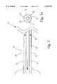
- FIG. 1is a partial schematic representation of the present invention.
- FIG. 1ais an end view of the multi-lumen cannula of FIG. 1.
- FIG. 2is a partial schematic representation of the multi-lumen cannula with the irrigation passage being the lumen of the hollow inner tube.
- FIG. 2ais an end view of the multi-lumen cannula of FIG. 2.
- FIG. 3is a partial schematic representation of the multi-lumen cannula with the suction passage being the lumen of the hollow inner tube.
- FIG. 3ais an end view of the multi-lumen cannula of FIG. 3.
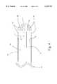
- FIG. 4is a partial schematic representation of a patient tip for the multi-lumen cannula shown in FIG. 1 and FIG. 1a.
- FIG. 5is a partial schematic representation of a patient tip for the multi-lumen cannula shown in FIG. 2 and FIG. 2a.
- FIG. 6is a partial schematic representation of a patient tip for the multi-lumen cannula shown in FIG. 3 and FIG. 3a.
- FIG. 7is a partial schematic representation of the handle showing the vent valve, the vent passageway, the irrigation control switch, and the irrigation controller.
- FIG. 8is a partial schematic representation of the handle showing the gas valve, the gas channel, and the two-input one-output connector.
- FIG. 1is a partial schematic representation of the apparatus embodying this invention.
- the surgical aspirator and irrigator system 10is comprised of a source of suction 11, a source of irrigation fluid 12, and a handle 13 to be held and manipulated by the surgeon.
- the source of suctionmay be the wall suction present in the operating room or it may be from a separate suction pump specifically designed for the lipoplasty procedure.
- the preferred method to deliver the irrigation fluidis to use a peristaltic pump and tubing set.
- the handle 13has a suction connector 15 for fluid communication with the source of suction 11 and an irrigation connector 16 for fluid communication with the source of irrigation fluid 12.
- the preferred connector for both suction and irrigationis a tubing barb threaded into the handle 13.
- the handle 13has a suction channel 17 in fluid communication with the suction connector 15, an irrigation channel 18 in fluid communication with the irrigation connector 16, and a vent passageway 32 in fluid communication between the ambient air about the handle 13 and the suction channel 17.
- a multi-lumen cannula 19 having at least two passages along an axis 36 thereofis supported on the distal end 14 of the handle 13.
- the preferred outside diameter for the multi-lumen cannulais between three and six millimeters.
- the multi-lumen cannulahas a first passage 20 for suction that is in fluid communication with the suction channel 17 and a second passage 21 for irrigation that is in fluid communication with the irrigation channel 18.
- the S-shaped double lines 37 shown in FIG. 1indicate a break-in-length and are used to scale the diagram to fit on one page.
- the S-shaped double lines 37are not part of the invention.
- the multi-lumen cannula 19has a cross-section perpendicular to the axis 36, the cross-section located anywhere along the length of the multi-lumen cannula, as shown in FIG. 1a.
- the first passage 20has a surface area of a unit length measured from the cross-section and a cross-sectional area at the cross-section. The surface area of a unit length of the first passage 20 can be calculated by multiplying the total perimeter of the first passage 20 measured in centimeters by a unit length, which is one centimeter.
- the total perimetermay have one component such as the inside circumference of a circular tube or it may have two components if one passage contains the other passage, in which case the total perimeter, for example, is the sum of the inside circumference of an outer circular tube and the outside circumference of a second circular tube contained within outer circular tube.
- the first passage 20has a resistive ratio that is the surface area of a unit length of the first passage 20 divided by the cross-sectional area of the first passage 20.
- the second passage 21has a surface area of a unit length measured from the cross-section and a cross-sectional area of the second passage 21 at the cross-section. The surface area of a unit length of the second passage can be calculated as described above using the dimensions of the second passage 21.
- the second passage 21has a resistive ratio that is the surface area of the unit length of the second passage divided by the cross-sectional area of the second passage 21.
- the resistive ratio of the first passage 20is between 0.5 and 1.5 times the resistive ratio of the second passage 21.
- the preferred valueis slightly less than 1.0 to account for the increase in viscosity of the aspirant relative to the irrigant.
- the resistive ratio of the first passage 20be between 0.7 and 0.9 times the resistive ratio of the second passage 21.
- the preferred embodiment of the multi-lumen cannula 19is shown in FIG. 2.
- a cross-section of the multi-lumen cannula 19 for this embodimentis shown in FIG. 2a.
- the multi-lumen cannula 19may include a hollow outer tube 22 with an inner surface 26 about and along its length and a hollow inner tube 23 residing within the hollow outer tube 22 with an outer surface 25 about and along its length.
- the preferred material for both tubesis thin-walled stainless steel tubing.
- the lumen of the hollow inner tube 23is preferably circular and is the second passage 21 of the multi-lumen cannula 19 for irrigation.
- An annular spaceis located between the outer surface 25 of the hollow inner tube 23 and the inner surface 26 of the hollow outer tube 22, the annular space being the first passage 20 of the multi-lumen cannula 19 for suction.
- the S-shaped double lines 37 shown in FIG. 2indicate a break-in-length and are used to scale the diagram to fit on one page.
- the S-shaped double lines 37are not part of the invention.
- FIG. 3A cross-section of the multi-lumen cannula 19 for this embodiment is shown in FIG. 3a.
- the multi-lumen cannula 19may include a hollow outer tube 22 with an inner surface 26 about and along its length and a hollow inner tube 23 residing within the hollow outer tube 22 with an outer surface 25 about and along its length.
- the preferred material for both tubesis thin-walled stainless steel tubing.
- the lumen of the hollow inner tube 23is preferably circular and is the first passage 20 of the multi-lumen cannula 19 for suction.
- An annular spaceis located between the outer surface 25 of the hollow inner tube 23 and the inner surface 26 of the hollow outer tube 22, the annular space being the second passage 21 of the multi-lumen cannula 19 for irrigation.
- the S-shaped double lines 37 shown in FIG. 3indicate a break-in-length and are used to scale the diagram to fit on one page.
- the S-shaped double lines 37are not part of the invention.
- FIG. 4A partial schematic diagram of a patient tip 28 is shown in FIG. 4.
- the patient tip 28 shown in FIG. 4mates with the multi-lumen cannula 19 shown in FIG. 1 and FIG. 1a.
- the patient tip 28is disposed away from the distal end of the handle and has a blunt or bullet-nosed shape.
- the blunt or bullet-nosed shape of the tipis to smooth passage of the multi-lumen cannula 19 through the tissues, thereby reducing trauma to the tissues and reducing the force required by the surgeon to push the multi-lumen cannula 19 through the tissues.
- the preferred material for the patient tipis stainless steel. Polymers such as polycarbonate, polyurethane, or polyethylene may also be used.
- the one or more ports 29 in or near the patient tip 28may be one or more ports 29 in or near the patient tip 28 for providing fluid communication between the tissue and the first passage 20 of the multi-lumen cannula 19.
- the one or more ports 29may be part of the patient tip 28 or they may be part of the multi-lumen cannula 19 near the patient tip 28.
- the one or more holes 30may be part of the patient tip 28 or they may be part of the multi-lumen cannula 19 near the patient tip 28.
- the S-shaped double lines 37 shown in FIG. 4indicate a break-in-length and are used to scale the diagram to fit on one page.
- the S-shaped double lines 37are not part of the invention.
- FIG. 5A partial schematic diagram of the preferred embodiment of a patient tip 28 is shown in FIG. 5.
- the patient tip 28 shown in FIG. 5mates with the multi-lumen cannula 19 shown in FIG. 2 and FIG. 2a.
- the patient tip 28is disposed away from the distal end of the handle and has a blunt or bullet-nosed shape.
- the blunt or bullet-nosed shape of the tipis to smooth passage of the multi-lumen cannula 19 through the tissues, thereby reducing trauma to the tissues and reducing the force required by the surgeon to push the multi-lumen cannula 19 through the tissues.
- the preferred material for the patient tipis stainless steel. Polymers such as polycarbonate, polyurethane, or polyethylene may also be used.
- the one or more ports 29 in or near the patient tip 28may be one or more ports 29 in or near the patient tip 28 for providing fluid communication between the tissue and the first passage 20 of the multi-lumen cannula 19.
- the one or more ports 29may be part of the patient tip 28 or they may be part of the multi-lumen cannula 19 near the patient tip 28.
- the one or more holes 30may be part of the patient tip 28 or they may be part of the multi-lumen cannula 19 near the patient tip 28.
- the S-shaped double lines 37 shown in FIG. 5indicate a break-in-length and are used to scale the diagram to fit on one page.
- the S-shaped double lines 37are not part of the invention.
- FIG. 6A partial schematic diagram of a third embodiment of a patient tip 28 is shown in FIG. 6.
- the patient tip 28 shown in FIG. 6mates with the multi-lumen cannula 19 shown in FIG. 3 and FIG. 3a.
- the patient tip 28is disposed away from the distal end of the handle and has a blunt or bullet-nosed shape.
- the blunt or bullet-nosed shape of the tipis to smooth passage of the multi-lumen cannula 19 through the tissues, thereby reducing trauma to the tissues and reducing the force required by the surgeon to push the multi-lumen cannula 19 through the tissues.
- the preferred material for the patient tipis stainless steel. Polymers such as polycarbonate, polyurethane, or polyethylene may also be used.
- the one or more ports 29 in or near the patient tip 28may be one or more ports 29 in or near the patient tip 28 for providing fluid communication between the tissue and the first passage 20 of the multi-lumen cannula 19.
- the one or more ports 29may be part of the patient tip 28 or they may be part of the multi-lumen cannula 19 near the patient tip 28.
- the one or more holes 30may be part of the patient tip 28 or they may be part of the multi-lumen cannula 19 near the patient tip 28.
- the S-shaped double lines 37 shown in FIG. 6indicate a break-in-length and are used to scale the diagram to fit on one page.
- the S-shaped double lines 37are not part of the invention.
- FIG. 7A partial schematic diagram of the handle 13 of the surgical aspirator and irrigator system 10 is shown in FIG. 7.
- the handle 13may include a vent valve 31 operatively coupled to the vent passageway 32 for selectively establishing fluid communication between the ambient air about the handle 13 and the suction channel 17 that passes through the handle 13.
- the preferred method for creating the vent valve 31is to provide access to the ambient air orifice of the vent passageway 32 so that a surgeon can open or occlude the orifice with his thumb or finger.
- a sliding or rotating mechanism that opens or occludes the vent passageway 32may also be used.
- the handlemay include an irrigation control switch 33 with an electrical connection 34 to an irrigation controller 35 located at and operatively connected to the source of irrigation fluid 12.
- the irrigation control switch 33is used for initiating or inhibiting the flow of irrigation fluid by electrically signaling the irrigation controller 35 through the electrical connection 34 in circuit therewith.
- the preferred style of irrigation switchis a two-position push-button toggle switch.
- the S-shaped double lines 37 shown in FIG. 7indicate a break-in-length and are used to scale the diagram to fit on one page.
- the S-shaped double lines 37are not part of the invention.
- the handle 13may include a gas connector 36 located on the handle 13 in fluid communication with a supply of filtered, pressurized, biocompatible gas.
- the handlehas a gas channel 43 in fluid communication with the gas connector 36 and a first input 39 of a two-input one-output connector 38.
- the two-input one-output connector 38is also commonly referred to as a ⁇ Y fitting ⁇ .
- a second input 40 of the two-input one-output connector 38is in fluid communication with the irrigation channel 18 passing through the handle 13.
- the preferred method of creating the gas channel 43is to use a piece of silicone tubing between the gas connector 36 and the first input 39.
- An output 41 of the two-input one-output connector 38is in fluid communication with the second passage 21 in the multi-lumen cannula 19.
- a gas control valve 42may be located on the handle 13. The gas control valve 42 selectively opens or closes so that the gas channel 43 passing through the handle 13 is in fluid communication with the first input 39 on the two-input one-output connector 38 when the gas control valve 42 is open or so that the gas channel 43 is sealed from fluid communication with the first input 39 on the two-input one-output connector 38 when the gas control valve 42 is closed.
- the preferable method of creating the gas control valve 42is to use a spring and wedge to pinch and occlude the gas channel 43 that has been formed with a piece of silicone tubing.
- the S-shaped double lines 37 shown in FIG. 8indicate a break-in-length and are used to scale the diagram to fit on one page.
- the S-shaped double lines 37are not part of the invention.
Landscapes
- Health & Medical Sciences (AREA)
- Heart & Thoracic Surgery (AREA)
- Biomedical Technology (AREA)
- Hematology (AREA)
- Veterinary Medicine (AREA)
- Vascular Medicine (AREA)
- Engineering & Computer Science (AREA)
- Anesthesiology (AREA)
- Public Health (AREA)
- General Health & Medical Sciences (AREA)
- Life Sciences & Earth Sciences (AREA)
- Animal Behavior & Ethology (AREA)
- Pulmonology (AREA)
- Surgery (AREA)
- Oral & Maxillofacial Surgery (AREA)
- External Artificial Organs (AREA)
- Surgical Instruments (AREA)
Abstract
Description
Claims (7)
Priority Applications (5)
| Application Number | Priority Date | Filing Date | Title |
|---|---|---|---|
| US09/196,042US6129701A (en) | 1998-11-19 | 1998-11-19 | Vented aspirator and method |
| US09/412,489US6379326B1 (en) | 1998-11-19 | 1999-10-05 | Lipoplasty method |
| AU17380/00AAU1738000A (en) | 1998-11-19 | 1999-11-17 | Vented aspirator and method |
| PCT/US1999/027451WO2000029045A1 (en) | 1998-11-19 | 1999-11-17 | Vented aspirator and method |
| US09/588,829US6540713B1 (en) | 1998-11-19 | 2000-06-07 | Vented aspirator and method |
Applications Claiming Priority (1)
| Application Number | Priority Date | Filing Date | Title |
|---|---|---|---|
| US09/196,042US6129701A (en) | 1998-11-19 | 1998-11-19 | Vented aspirator and method |
Related Child Applications (2)
| Application Number | Title | Priority Date | Filing Date |
|---|---|---|---|
| US09/412,489Continuation-In-PartUS6379326B1 (en) | 1998-11-19 | 1999-10-05 | Lipoplasty method |
| US09/588,829Continuation-In-PartUS6540713B1 (en) | 1998-11-19 | 2000-06-07 | Vented aspirator and method |
Publications (1)
| Publication Number | Publication Date |
|---|---|
| US6129701Atrue US6129701A (en) | 2000-10-10 |
Family
ID=22723905
Family Applications (3)
| Application Number | Title | Priority Date | Filing Date |
|---|---|---|---|
| US09/196,042Expired - LifetimeUS6129701A (en) | 1998-11-19 | 1998-11-19 | Vented aspirator and method |
| US09/412,489Expired - LifetimeUS6379326B1 (en) | 1998-11-19 | 1999-10-05 | Lipoplasty method |
| US09/588,829Expired - LifetimeUS6540713B1 (en) | 1998-11-19 | 2000-06-07 | Vented aspirator and method |
Family Applications After (2)
| Application Number | Title | Priority Date | Filing Date |
|---|---|---|---|
| US09/412,489Expired - LifetimeUS6379326B1 (en) | 1998-11-19 | 1999-10-05 | Lipoplasty method |
| US09/588,829Expired - LifetimeUS6540713B1 (en) | 1998-11-19 | 2000-06-07 | Vented aspirator and method |
Country Status (3)
| Country | Link |
|---|---|
| US (3) | US6129701A (en) |
| AU (1) | AU1738000A (en) |
| WO (1) | WO2000029045A1 (en) |
Cited By (51)
| Publication number | Priority date | Publication date | Assignee | Title |
|---|---|---|---|---|
| US6350250B1 (en)* | 1998-08-12 | 2002-02-26 | Valentin Lorenzo Crosa Dorado | Vacuum dosing device |
| US6379326B1 (en)* | 1998-11-19 | 2002-04-30 | William Cimino | Lipoplasty method |
| US6605062B1 (en)* | 1999-09-02 | 2003-08-12 | Advanced Cardiovascular Systems, Inc. | Catheter for guidewire support or exchange |
| US20030204200A1 (en)* | 2002-04-26 | 2003-10-30 | Mark Rufener | Splash shield for use with debridement devices |
| US6676677B2 (en) | 2001-05-11 | 2004-01-13 | Jeffrey A. Klein | Liposuction cannula with abrading apertures |
| US6716194B1 (en)* | 2001-05-04 | 2004-04-06 | Sound Surgical Technologies Llc | Surgical aspiration device employing continuous, precise venting |
| US20040082936A1 (en)* | 1999-01-07 | 2004-04-29 | Moris Topaz | Biocompatible, injectable aqueous solution for use in ultrasound energy assisted surgery |
| US20040092895A1 (en)* | 2002-11-07 | 2004-05-13 | Harmon Kim R. | Soft contact tip for use with a hand-held debridement device |
| USD490517S1 (en) | 2002-12-20 | 2004-05-25 | Zimmer Orthopaedic Surgical Products, Inc. | Debridement tip |
| USD490518S1 (en) | 2003-02-03 | 2004-05-25 | Zimmer Orthopaedic Surgical Products, Inc. | Debridement tip |
| US20040122447A1 (en)* | 2002-12-19 | 2004-06-24 | Harmon Kim R. | Brush tip for use with a hand-held debridement device |
| US20040151979A1 (en)* | 2003-02-03 | 2004-08-05 | Donaldson Timothy A. | Battery pack for use with a hand-held debridement device |
| US20040236307A1 (en)* | 2003-05-21 | 2004-11-25 | Klein Jeffrey A. | Infiltration cannula |
| US20040236313A1 (en)* | 2003-05-21 | 2004-11-25 | Klein Jeffrey A. | Infiltration cannula |
| US6830556B2 (en)* | 2002-01-08 | 2004-12-14 | Zimmer Orthopaedic Surgical Products, Inc. | Debridement extension providing irrigation and mechanical scrubbing for removal of dead, devitalized, or contaminated tissue from a wound |
| US20050061335A1 (en)* | 1999-01-07 | 2005-03-24 | Morris Topaz | Irrigation solution for use in ultrasound energy assisted surgery |
| WO2005061025A1 (en)* | 2003-12-22 | 2005-07-07 | Medela Holding Ag | Drainage apparatus and method |
| WO2006039511A2 (en) | 2004-09-30 | 2006-04-13 | Boston Scientific Scimed, Inc. | System and method of obstruction removal |
| RU2322268C1 (en)* | 2003-12-22 | 2008-04-20 | Медела Холдинг Аг | Drainage device and method of removing liquid from body's cavity |
| US8105310B2 (en) | 2003-05-21 | 2012-01-31 | Klein Jeffrey A | Infiltration cannula |
| USRE44049E1 (en)* | 2000-04-06 | 2013-03-05 | Garrett D. Herzon | Bipolar handheld nerve locator and evaluator |
| US20150012022A1 (en)* | 2010-09-29 | 2015-01-08 | Sound Surgical Technologies Llc | Power assisted lipoplasty |
| US8957060B2 (en) | 2009-11-30 | 2015-02-17 | Jeffrey Alan KLEIN | Tumescent antibiotic solution |
| US20150080853A1 (en)* | 2006-01-09 | 2015-03-19 | Smalling Medical Ventures, Llc | Aspiration Thrombectomy Catheter System, And Associated Methods |
| US20150230825A1 (en)* | 1999-08-26 | 2015-08-20 | Axia Medsciences, Llc | Devices and systems for treating the skin using vacuum |
| US20150335842A1 (en)* | 2009-07-31 | 2015-11-26 | Avent, Inc. | Subglottic suctioning system |
| US20160106450A1 (en)* | 2014-10-16 | 2016-04-21 | Gyrus Acmi, Inc. D.B.A. Olympus Surgical Technologies America | Variable Suction Control |
| EP3071090A1 (en)* | 2013-11-21 | 2016-09-28 | Motus Gi Medical Technologies Ltd. | Distal front end for coordinated positioning of an endoscope with a suction device |
| US9474886B2 (en) | 2005-12-30 | 2016-10-25 | Edge Systems Llc | Removable tips for skin treatment systems |
| US9486615B2 (en) | 2008-01-04 | 2016-11-08 | Edge Systems Llc | Microdermabrasion apparatus and method |
| US20160325063A1 (en)* | 2013-01-03 | 2016-11-10 | Hamid Khosrowshahi | System for removing infectious secretions |
| US9498610B2 (en) | 2014-12-23 | 2016-11-22 | Edge Systems Llc | Devices and methods for treating the skin using a rollerball or a wicking member |
| US9566088B2 (en) | 2006-03-29 | 2017-02-14 | Edge Systems Llc | Devices, systems and methods for treating the skin |
| US9642997B2 (en) | 2008-01-29 | 2017-05-09 | Edge Systems Llc | Devices for treating skin using treatment materials located along a tip |
| US10172644B2 (en) | 2006-03-29 | 2019-01-08 | Edge Systems Llc | Devices, systems and methods for treating the skin |
| US10179229B2 (en) | 2014-12-23 | 2019-01-15 | Edge Systems Llc | Devices and methods for treating the skin using a porous member |
| US10238812B2 (en) | 2013-03-15 | 2019-03-26 | Edge Systems Llc | Skin treatment systems and methods using needles |
| RU198243U1 (en)* | 2020-02-13 | 2020-06-25 | Общество с ограниченной ответственностью «Наука и Инновации» | NOZZLE WITH STRUCTURING NOZZLES ON THE TUBE OF THE IRRIGATOR-ASpirator TUBE |
| US10993743B2 (en) | 2013-03-15 | 2021-05-04 | Edge Systems Llc | Devices, systems and methods for treating the skin |
| US11020577B2 (en) | 2008-01-29 | 2021-06-01 | Edge Systems Llc | Devices and systems for treating skin surfaces |
| US11241357B2 (en) | 2015-07-08 | 2022-02-08 | Edge Systems Llc | Devices, systems and methods for promoting hair growth |
| US20220040398A1 (en)* | 2019-04-26 | 2022-02-10 | Das Innovations Pty Ltd | Dual cannulated suction and delivery device |
| RU2778006C1 (en)* | 2021-08-16 | 2022-08-12 | Федеральное государственное бюджетное образовательное учреждение высшего образования "Ставропольский государственный медицинский университет" Министерства здравоохранения Российской Федерации (ФГБОУ ВО СтГМУ Минздрава России) | Attachment for an aquapurator |
| US11672695B2 (en) | 2018-03-22 | 2023-06-13 | Artivion, Inc. | Central nervous system localized hypothermia apparatus and methods |
| WO2023192562A1 (en)* | 2022-03-31 | 2023-10-05 | Mayo Foundation For Medical Education And Research | Suction instrument and method for video-assisted thoracoscopic surgery |
| US11904085B2 (en) | 2013-08-29 | 2024-02-20 | Motus Gi Medical Technologies Ltd. | Colon cleaning system with automatic self-purging features |
| USD1016615S1 (en) | 2021-09-10 | 2024-03-05 | Hydrafacial Llc | Container for a skin treatment device |
| USD1042807S1 (en) | 2021-10-11 | 2024-09-17 | Hydrafacial Llc | Skin treatment tip |
| USD1065551S1 (en) | 2021-09-10 | 2025-03-04 | Hydrafacial Llc | Skin treatment device |
| US12295618B2 (en) | 2020-01-06 | 2025-05-13 | Hydrafacial Llc | Skin treatment tool applicator tip |
| USD1084369S1 (en) | 2023-02-10 | 2025-07-15 | Hydrafacial Llc | Skin treatment tip |
Families Citing this family (27)
| Publication number | Priority date | Publication date | Assignee | Title |
|---|---|---|---|---|
| US6635070B2 (en)* | 2001-05-21 | 2003-10-21 | Bacchus Vascular, Inc. | Apparatus and methods for capturing particulate material within blood vessels |
| EP1441777A4 (en)* | 2001-07-17 | 2007-05-30 | Kerberos Proximal Solutions | Fluid exchange system for controlled and localized irrigation and aspiration |
| US7018354B2 (en)* | 2001-11-08 | 2006-03-28 | El Hassane Tazi | Liposuction devices and methods and surrounding aspiration systems and methods |
| RU2247544C1 (en)* | 2003-06-09 | 2005-03-10 | Государственное образовательное учреждение высшего профессионального образования "Алтайский государственный технический университет им. И.И. Ползунова" | Method for controlling ultrasonic liposuction process |
| EP1687056B9 (en)* | 2003-11-20 | 2013-09-11 | Children's Medical Center Corporation | Trocar for use during endoscopy |
| US20050137581A1 (en)* | 2003-12-17 | 2005-06-23 | Kouros Azar | Liposuction/tubing coupling for providing rotational movement |
| US20060074344A1 (en)* | 2004-09-29 | 2006-04-06 | Hibner John A | Fluid control for biopsy device |
| US7276032B2 (en)* | 2004-09-29 | 2007-10-02 | Ethicon Endo-Surgery, Inc. | Biopsy apparatus and method |
| US20060293725A1 (en)* | 2005-06-24 | 2006-12-28 | Boris Rubinsky | Methods and systems for treating fatty tissue sites using electroporation |
| GR20050100452A (en) | 2005-09-02 | 2007-04-25 | Estelle Enterprises Limited | Fluid exchange catheter's system |
| EP2496277A1 (en)* | 2009-11-06 | 2012-09-12 | James B. Stiehl | Actuated self unplugging surgical sucker wand |
| AU2011329278B2 (en) | 2010-11-17 | 2016-06-09 | Kci Licensing, Inc. | Systems and methods for subcutaneous administration of reduced pressure employing reconfigurable lumens |
| US8475482B2 (en) | 2011-02-17 | 2013-07-02 | Gyrus Ent L.L.C. | Surgical instrument with distal suction capability |
| CN203564591U (en)* | 2011-05-12 | 2014-04-30 | 梓源生技有限公司 | Double chamber head and drainage irrigation system |
| WO2013059263A1 (en)* | 2011-10-17 | 2013-04-25 | Sound Surgical Technologies, Llc | Ultrasonic probe for treating cellulite |
| WO2013123455A1 (en) | 2012-02-15 | 2013-08-22 | Intuitive Surgical Operations, Inc. | Low friction cannula seals for minimally invasive robotic surgery |
| US8721595B2 (en) | 2012-05-11 | 2014-05-13 | Stiehl Technologies, Llc | Surgical suction wand |
| WO2013177038A2 (en)* | 2012-05-21 | 2013-11-28 | Lipovera, Llc | A vibrational device for fat insertion during fat transplantation |
| US9248228B2 (en) | 2013-01-18 | 2016-02-02 | Peter L. Bono | Suction and irrigation apparatus with anti-clogging capability |
| US10085727B2 (en)* | 2013-02-08 | 2018-10-02 | Carefusion 2200, Inc. | Vacuum assisted handheld biopsy device |
| US9572626B2 (en)* | 2013-02-15 | 2017-02-21 | Intuitive Surgical Operations, Inc. | Actuated cannula seal |
| US20160303310A1 (en)* | 2015-04-17 | 2016-10-20 | ShineIN Biotechnology Co., Ltd. | Suction-irrigation head |
| CN106137391A (en)* | 2015-04-27 | 2016-11-23 | 善医生技股份有限公司 | Diversion type lavage head structure |
| CN105497998A (en)* | 2016-01-16 | 2016-04-20 | 刘静 | Minimally-invasive negative-pressure extraction part for skin tissue |
| CN108175928B (en)* | 2018-01-15 | 2020-12-01 | 苏州创力波科技有限公司 | A kind of ENT patient's nose medicine nursing device |
| US11213316B2 (en) | 2018-03-09 | 2022-01-04 | The Children's Medical Center Corporation | Gasket with multi-leaflet valve for surgical port apparatus |
| WO2021119286A1 (en)* | 2019-12-10 | 2021-06-17 | Revela Medical, Inc. | Method and apparatus for emulsifying tissue |
Citations (15)
| Publication number | Priority date | Publication date | Assignee | Title |
|---|---|---|---|---|
| US4548197A (en)* | 1983-03-22 | 1985-10-22 | Olympus Optical Co., Ltd. | Air and liquid supplying device for endoscope |
| US4596533A (en)* | 1985-03-06 | 1986-06-24 | Buddy L Corporation | Toy work vehicle and trailer assembly |
| US4735605A (en)* | 1986-09-15 | 1988-04-05 | Swartz Barry E | Lipectomy device having round cutting edges |
| US4886491A (en)* | 1988-02-29 | 1989-12-12 | Tulio Parisi | Liposuction procedure with ultrasonic probe |
| US5013300A (en)* | 1989-03-09 | 1991-05-07 | Williams James D | Apparatus for suction lipectomy surgery |
| US5112302A (en)* | 1990-07-16 | 1992-05-12 | Cucin Robert L | Method and apparatus for performing liposuction |
| US5163433A (en)* | 1989-11-01 | 1992-11-17 | Olympus Optical Co., Ltd. | Ultrasound type treatment apparatus |
| US5181907A (en)* | 1990-03-20 | 1993-01-26 | Hilton Becker | Cannula and method for liposuction |
| US5348535A (en)* | 1990-12-14 | 1994-09-20 | Rocin Laboratories, Inc. | Power-assisted liposuction instrument and cannula assembly therefor |
| US5429596A (en)* | 1992-10-09 | 1995-07-04 | Symbiosis Corporation | Endoscopic electrosurgical suction-irrigation instrument |
| US5447494A (en)* | 1990-01-26 | 1995-09-05 | American Hydro-Surgical Instruments, Inc. | Composite irrigation and suction probe |
| US5569178A (en)* | 1995-10-20 | 1996-10-29 | Henley; Julian L. | Power assisted suction lipectomy device |
| US5643198A (en)* | 1990-12-14 | 1997-07-01 | Rocin Laboratories, Inc. | Power-assisted liposuction instrument and cannula assembly therefor |
| US5665101A (en)* | 1996-04-01 | 1997-09-09 | Linvatec Corporation | Endoscopic or open lipectomy instrument |
| US5766194A (en)* | 1996-12-23 | 1998-06-16 | Georgia Skin And Cancer Clinic, Pc | Surgical apparatus for tissue removal |
Family Cites Families (5)
| Publication number | Priority date | Publication date | Assignee | Title |
|---|---|---|---|---|
| US4735606A (en)* | 1982-10-12 | 1988-04-05 | Sherwood Medical Company | Chest drainage apparatus |
| US4775365A (en)* | 1986-09-15 | 1988-10-04 | Barry Swartz | Lipectomy cannula |
| US5527273A (en)* | 1994-10-06 | 1996-06-18 | Misonix, Inc. | Ultrasonic lipectomy probe and method for manufacture |
| US5738648A (en)* | 1996-01-23 | 1998-04-14 | Valleylab Inc | Method and apparatus for a valve and irrigator |
| US6129701A (en)* | 1998-11-19 | 2000-10-10 | Sound Surgical Technologies, Llc | Vented aspirator and method |
- 1998
- 1998-11-19USUS09/196,042patent/US6129701A/ennot_activeExpired - Lifetime
- 1999
- 1999-10-05USUS09/412,489patent/US6379326B1/ennot_activeExpired - Lifetime
- 1999-11-17AUAU17380/00Apatent/AU1738000A/ennot_activeAbandoned
- 1999-11-17WOPCT/US1999/027451patent/WO2000029045A1/enactiveApplication Filing
- 2000
- 2000-06-07USUS09/588,829patent/US6540713B1/ennot_activeExpired - Lifetime
Patent Citations (15)
| Publication number | Priority date | Publication date | Assignee | Title |
|---|---|---|---|---|
| US4548197A (en)* | 1983-03-22 | 1985-10-22 | Olympus Optical Co., Ltd. | Air and liquid supplying device for endoscope |
| US4596533A (en)* | 1985-03-06 | 1986-06-24 | Buddy L Corporation | Toy work vehicle and trailer assembly |
| US4735605A (en)* | 1986-09-15 | 1988-04-05 | Swartz Barry E | Lipectomy device having round cutting edges |
| US4886491A (en)* | 1988-02-29 | 1989-12-12 | Tulio Parisi | Liposuction procedure with ultrasonic probe |
| US5013300A (en)* | 1989-03-09 | 1991-05-07 | Williams James D | Apparatus for suction lipectomy surgery |
| US5163433A (en)* | 1989-11-01 | 1992-11-17 | Olympus Optical Co., Ltd. | Ultrasound type treatment apparatus |
| US5447494A (en)* | 1990-01-26 | 1995-09-05 | American Hydro-Surgical Instruments, Inc. | Composite irrigation and suction probe |
| US5181907A (en)* | 1990-03-20 | 1993-01-26 | Hilton Becker | Cannula and method for liposuction |
| US5112302A (en)* | 1990-07-16 | 1992-05-12 | Cucin Robert L | Method and apparatus for performing liposuction |
| US5348535A (en)* | 1990-12-14 | 1994-09-20 | Rocin Laboratories, Inc. | Power-assisted liposuction instrument and cannula assembly therefor |
| US5643198A (en)* | 1990-12-14 | 1997-07-01 | Rocin Laboratories, Inc. | Power-assisted liposuction instrument and cannula assembly therefor |
| US5429596A (en)* | 1992-10-09 | 1995-07-04 | Symbiosis Corporation | Endoscopic electrosurgical suction-irrigation instrument |
| US5569178A (en)* | 1995-10-20 | 1996-10-29 | Henley; Julian L. | Power assisted suction lipectomy device |
| US5665101A (en)* | 1996-04-01 | 1997-09-09 | Linvatec Corporation | Endoscopic or open lipectomy instrument |
| US5766194A (en)* | 1996-12-23 | 1998-06-16 | Georgia Skin And Cancer Clinic, Pc | Surgical apparatus for tissue removal |
Cited By (109)
| Publication number | Priority date | Publication date | Assignee | Title |
|---|---|---|---|---|
| US6350250B1 (en)* | 1998-08-12 | 2002-02-26 | Valentin Lorenzo Crosa Dorado | Vacuum dosing device |
| US6379326B1 (en)* | 1998-11-19 | 2002-04-30 | William Cimino | Lipoplasty method |
| US6540713B1 (en)* | 1998-11-19 | 2003-04-01 | Sound Surgical Technologies, Llc | Vented aspirator and method |
| US20040082936A1 (en)* | 1999-01-07 | 2004-04-29 | Moris Topaz | Biocompatible, injectable aqueous solution for use in ultrasound energy assisted surgery |
| US20050061335A1 (en)* | 1999-01-07 | 2005-03-24 | Morris Topaz | Irrigation solution for use in ultrasound energy assisted surgery |
| US9775646B2 (en)* | 1999-08-26 | 2017-10-03 | Axia Medsciences, Llc | Devices and systems for treating the skin using vacuum |
| US20150230825A1 (en)* | 1999-08-26 | 2015-08-20 | Axia Medsciences, Llc | Devices and systems for treating the skin using vacuum |
| US9468464B2 (en) | 1999-08-26 | 2016-10-18 | Axia Medsciences, Llc | Methods for treating the skin using vacuum |
| US6605062B1 (en)* | 1999-09-02 | 2003-08-12 | Advanced Cardiovascular Systems, Inc. | Catheter for guidewire support or exchange |
| USRE44049E1 (en)* | 2000-04-06 | 2013-03-05 | Garrett D. Herzon | Bipolar handheld nerve locator and evaluator |
| US6716194B1 (en)* | 2001-05-04 | 2004-04-06 | Sound Surgical Technologies Llc | Surgical aspiration device employing continuous, precise venting |
| US6676677B2 (en) | 2001-05-11 | 2004-01-13 | Jeffrey A. Klein | Liposuction cannula with abrading apertures |
| US20040044331A1 (en)* | 2001-05-11 | 2004-03-04 | Klein Jeffrey A. | Liposuction cannula with abrading apertures |
| US6830556B2 (en)* | 2002-01-08 | 2004-12-14 | Zimmer Orthopaedic Surgical Products, Inc. | Debridement extension providing irrigation and mechanical scrubbing for removal of dead, devitalized, or contaminated tissue from a wound |
| US20030204200A1 (en)* | 2002-04-26 | 2003-10-30 | Mark Rufener | Splash shield for use with debridement devices |
| US20040092895A1 (en)* | 2002-11-07 | 2004-05-13 | Harmon Kim R. | Soft contact tip for use with a hand-held debridement device |
| US20040122447A1 (en)* | 2002-12-19 | 2004-06-24 | Harmon Kim R. | Brush tip for use with a hand-held debridement device |
| USD490517S1 (en) | 2002-12-20 | 2004-05-25 | Zimmer Orthopaedic Surgical Products, Inc. | Debridement tip |
| US20040151979A1 (en)* | 2003-02-03 | 2004-08-05 | Donaldson Timothy A. | Battery pack for use with a hand-held debridement device |
| USD490518S1 (en) | 2003-02-03 | 2004-05-25 | Zimmer Orthopaedic Surgical Products, Inc. | Debridement tip |
| US8246587B2 (en) | 2003-05-21 | 2012-08-21 | Klein Jeffrey A | Infiltration cannula |
| US8506551B2 (en) | 2003-05-21 | 2013-08-13 | Jeffrey A. Klein | Infiltration cannula |
| US20070106234A1 (en)* | 2003-05-21 | 2007-05-10 | Klein Jeffrey A | Infiltration cannula |
| US20040236313A1 (en)* | 2003-05-21 | 2004-11-25 | Klein Jeffrey A. | Infiltration cannula |
| US7914504B2 (en) | 2003-05-21 | 2011-03-29 | Klein Jeffrey A | Infiltration cannula |
| US20110152837A1 (en)* | 2003-05-21 | 2011-06-23 | Klein Jeffrey A | Infiltration cannula |
| US20040236307A1 (en)* | 2003-05-21 | 2004-11-25 | Klein Jeffrey A. | Infiltration cannula |
| US8529541B2 (en) | 2003-05-21 | 2013-09-10 | Jeffrey A. Klein | Infiltration cannula |
| US8105310B2 (en) | 2003-05-21 | 2012-01-31 | Klein Jeffrey A | Infiltration cannula |
| US8512292B2 (en) | 2003-05-21 | 2013-08-20 | Jeffrey A. Klein | Infiltration cannula |
| US7976533B2 (en) | 2003-12-22 | 2011-07-12 | Medela Holding Ag | Drainage apparatus and method |
| US8486051B2 (en) | 2003-12-22 | 2013-07-16 | Medela Holding Ag | Drainage apparatus and method |
| CN1859935B (en)* | 2003-12-22 | 2011-07-20 | 美德乐控股公司 | Drainage devices and methods |
| US20070078444A1 (en)* | 2003-12-22 | 2007-04-05 | Michael Larsson | Drainage apparatus and method |
| RU2322268C1 (en)* | 2003-12-22 | 2008-04-20 | Медела Холдинг Аг | Drainage device and method of removing liquid from body's cavity |
| WO2005061025A1 (en)* | 2003-12-22 | 2005-07-07 | Medela Holding Ag | Drainage apparatus and method |
| US10322083B2 (en) | 2004-06-25 | 2019-06-18 | Hk Pharma | Tumescent drug delivery |
| US9623030B2 (en) | 2004-06-25 | 2017-04-18 | Jeffrey Alan KLEIN | Tumescent antibiotic solution |
| WO2006039511A3 (en)* | 2004-09-30 | 2006-07-06 | Boston Scient Scimed Inc | System and method of obstruction removal |
| US8353860B2 (en) | 2004-09-30 | 2013-01-15 | Boston Scientific Scimed, Inc. | Device for obstruction removal with specific tip structure |
| WO2006039511A2 (en) | 2004-09-30 | 2006-04-13 | Boston Scientific Scimed, Inc. | System and method of obstruction removal |
| US11446477B2 (en) | 2005-12-30 | 2022-09-20 | Hydrafacial Llc | Devices and methods for treating skin |
| US9662482B2 (en) | 2005-12-30 | 2017-05-30 | Edge Systems Llc | Methods and systems for extraction of materials from skin |
| US9814868B2 (en) | 2005-12-30 | 2017-11-14 | Edge Systems Llc | Tip with embedded materials for skin treatment |
| US9474886B2 (en) | 2005-12-30 | 2016-10-25 | Edge Systems Llc | Removable tips for skin treatment systems |
| US12053607B2 (en) | 2005-12-30 | 2024-08-06 | Hydrafacial Llc | Devices and methods for treating skin |
| US11547840B2 (en) | 2005-12-30 | 2023-01-10 | Hydrafacial Llc | Devices and methods for treating skin |
| US10357641B2 (en) | 2005-12-30 | 2019-07-23 | Edge Systems Llc | Tips for skin treatment device |
| US9550052B2 (en) | 2005-12-30 | 2017-01-24 | Edge Systems Llc | Console system for the treatment of skin |
| US11612726B2 (en) | 2005-12-30 | 2023-03-28 | Hydrafacial Llc | Devices and methods for treating skin |
| US11865287B2 (en) | 2005-12-30 | 2024-01-09 | Hydrafacial Llc | Devices and methods for treating skin |
| US10357642B2 (en) | 2005-12-30 | 2019-07-23 | Edge Systems Llc | Removable tips for use with skin treatment systems |
| US20150080853A1 (en)* | 2006-01-09 | 2015-03-19 | Smalling Medical Ventures, Llc | Aspiration Thrombectomy Catheter System, And Associated Methods |
| US10188409B2 (en)* | 2006-01-09 | 2019-01-29 | Smalling Medical Ventures, Llc | Aspiration thrombectomy catheter system, and associated methods |
| US9566088B2 (en) | 2006-03-29 | 2017-02-14 | Edge Systems Llc | Devices, systems and methods for treating the skin |
| US11717326B2 (en) | 2006-03-29 | 2023-08-08 | Hydrafacial Llc | Devices, systems and methods for treating the skin |
| US10251675B2 (en) | 2006-03-29 | 2019-04-09 | Edge Systems Llc | Devices, systems and methods for treating the skin |
| US10172644B2 (en) | 2006-03-29 | 2019-01-08 | Edge Systems Llc | Devices, systems and methods for treating the skin |
| US10556096B2 (en) | 2008-01-04 | 2020-02-11 | Edge Systems Llc | Devices and methods for skin treatment |
| US9486615B2 (en) | 2008-01-04 | 2016-11-08 | Edge Systems Llc | Microdermabrasion apparatus and method |
| US11883621B2 (en) | 2008-01-04 | 2024-01-30 | Hydrafacial Llc | Devices and methods for skin treatment |
| US12186513B2 (en) | 2008-01-29 | 2025-01-07 | Hydrafacial Llc | Devices, systems and methods for skin treatment |
| US10556097B2 (en) | 2008-01-29 | 2020-02-11 | Edge Systems Llc | Devices for treating skin using treatment materials located along a tip |
| US11020577B2 (en) | 2008-01-29 | 2021-06-01 | Edge Systems Llc | Devices and systems for treating skin surfaces |
| US12161830B2 (en) | 2008-01-29 | 2024-12-10 | Hydrafacial Llc | Devices, systems, and methods for treating the skin |
| US9642997B2 (en) | 2008-01-29 | 2017-05-09 | Edge Systems Llc | Devices for treating skin using treatment materials located along a tip |
| US12005217B2 (en) | 2008-01-29 | 2024-06-11 | Hydrafacial Llc | Devices, systems and methods for skin treatment |
| US20150335842A1 (en)* | 2009-07-31 | 2015-11-26 | Avent, Inc. | Subglottic suctioning system |
| US10245401B2 (en)* | 2009-07-31 | 2019-04-02 | Avent, Inc. | Subglottic suctioning system |
| US8957060B2 (en) | 2009-11-30 | 2015-02-17 | Jeffrey Alan KLEIN | Tumescent antibiotic solution |
| US10004836B2 (en)* | 2010-09-29 | 2018-06-26 | Sound Surgical Technologies Llc | Power assisted lipoplasty |
| US20150012022A1 (en)* | 2010-09-29 | 2015-01-08 | Sound Surgical Technologies Llc | Power assisted lipoplasty |
| US20160325063A1 (en)* | 2013-01-03 | 2016-11-10 | Hamid Khosrowshahi | System for removing infectious secretions |
| US10188816B2 (en)* | 2013-01-03 | 2019-01-29 | Flosure Technologies Llc | System for removing infectious secretions |
| US11903615B2 (en) | 2013-03-15 | 2024-02-20 | Hydrafacial Llc | Devices, systems and methods for treating the skin |
| US10993743B2 (en) | 2013-03-15 | 2021-05-04 | Edge Systems Llc | Devices, systems and methods for treating the skin |
| US11202657B2 (en) | 2013-03-15 | 2021-12-21 | Edge Systems Llc | Devices, systems and methods for treating the skin |
| US11213321B2 (en) | 2013-03-15 | 2022-01-04 | Edge Systems Llc | Devices, systems and methods for treating the skin |
| US10238812B2 (en) | 2013-03-15 | 2019-03-26 | Edge Systems Llc | Skin treatment systems and methods using needles |
| US11517350B2 (en) | 2013-03-15 | 2022-12-06 | Hydrafacial Llc | Devices, systems and methods for treating the skin |
| US11904085B2 (en) | 2013-08-29 | 2024-02-20 | Motus Gi Medical Technologies Ltd. | Colon cleaning system with automatic self-purging features |
| EP3071090A1 (en)* | 2013-11-21 | 2016-09-28 | Motus Gi Medical Technologies Ltd. | Distal front end for coordinated positioning of an endoscope with a suction device |
| CN107106738A (en)* | 2014-10-16 | 2017-08-29 | 捷锐士阿希迈公司(以奥林巴斯美国外科技术名义) | Variable Suction Control |
| CN110947037A (en)* | 2014-10-16 | 2020-04-03 | 捷锐士阿希迈公司(以奥林巴斯美国外科技术名义) | Device for a medical instrument and method for providing the device |
| CN110947037B (en)* | 2014-10-16 | 2022-07-08 | 捷锐士阿希迈公司(以奥林巴斯美国外科技术名义) | Device for a medical instrument and method for providing the device |
| US20160106450A1 (en)* | 2014-10-16 | 2016-04-21 | Gyrus Acmi, Inc. D.B.A. Olympus Surgical Technologies America | Variable Suction Control |
| JP2017531508A (en)* | 2014-10-16 | 2017-10-26 | ジャイラス・エーシーエムアイ・インコーポレーテッド | Variable suction control |
| US10166036B2 (en)* | 2014-10-16 | 2019-01-01 | Gyrus Acmi, Inc. | Variable suction control |
| US11607484B2 (en)* | 2014-10-16 | 2023-03-21 | Gyrus Acmi, Inc. | Variable suction control |
| US20190133621A1 (en)* | 2014-10-16 | 2019-05-09 | Gyrus Acmi, Inc. D/B/A Olympus Surgical Technologies America | Variable Suction Control |
| US11224728B2 (en) | 2014-12-23 | 2022-01-18 | Edge Systems Llc | Devices and methods for treating the skin using a porous member |
| US10179229B2 (en) | 2014-12-23 | 2019-01-15 | Edge Systems Llc | Devices and methods for treating the skin using a porous member |
| US11744999B2 (en) | 2014-12-23 | 2023-09-05 | Hydra Facial LLC | Devices and methods for treating the skin |
| US10035007B2 (en) | 2014-12-23 | 2018-07-31 | Edge Systems Llc | Devices and methods for treating the skin |
| US11806495B2 (en) | 2014-12-23 | 2023-11-07 | Hydrafacial Llc | Devices and methods for treating the skin |
| US11925780B2 (en) | 2014-12-23 | 2024-03-12 | Hydrafacial Llc | Devices and methods for treating the skin |
| US9498610B2 (en) | 2014-12-23 | 2016-11-22 | Edge Systems Llc | Devices and methods for treating the skin using a rollerball or a wicking member |
| US11241357B2 (en) | 2015-07-08 | 2022-02-08 | Edge Systems Llc | Devices, systems and methods for promoting hair growth |
| US11672695B2 (en) | 2018-03-22 | 2023-06-13 | Artivion, Inc. | Central nervous system localized hypothermia apparatus and methods |
| US20220040398A1 (en)* | 2019-04-26 | 2022-02-10 | Das Innovations Pty Ltd | Dual cannulated suction and delivery device |
| US12295618B2 (en) | 2020-01-06 | 2025-05-13 | Hydrafacial Llc | Skin treatment tool applicator tip |
| RU198243U1 (en)* | 2020-02-13 | 2020-06-25 | Общество с ограниченной ответственностью «Наука и Инновации» | NOZZLE WITH STRUCTURING NOZZLES ON THE TUBE OF THE IRRIGATOR-ASpirator TUBE |
| RU2778006C1 (en)* | 2021-08-16 | 2022-08-12 | Федеральное государственное бюджетное образовательное учреждение высшего образования "Ставропольский государственный медицинский университет" Министерства здравоохранения Российской Федерации (ФГБОУ ВО СтГМУ Минздрава России) | Attachment for an aquapurator |
| RU2778006C9 (en)* | 2021-08-16 | 2022-12-06 | Федеральное государственное бюджетное образовательное учреждение высшего образования "Ставропольский государственный медицинский университет" Министерства здравоохранения Российской Федерации (ФГБОУ ВО СтГМУ Минздрава России) | Attachment for an aquapurator |
| USD1016615S1 (en) | 2021-09-10 | 2024-03-05 | Hydrafacial Llc | Container for a skin treatment device |
| USD1065551S1 (en) | 2021-09-10 | 2025-03-04 | Hydrafacial Llc | Skin treatment device |
| USD1042807S1 (en) | 2021-10-11 | 2024-09-17 | Hydrafacial Llc | Skin treatment tip |
| WO2023192562A1 (en)* | 2022-03-31 | 2023-10-05 | Mayo Foundation For Medical Education And Research | Suction instrument and method for video-assisted thoracoscopic surgery |
| USD1084369S1 (en) | 2023-02-10 | 2025-07-15 | Hydrafacial Llc | Skin treatment tip |
Also Published As
| Publication number | Publication date |
|---|---|
| US6379326B1 (en) | 2002-04-30 |
| US6540713B1 (en) | 2003-04-01 |
| WO2000029045A1 (en) | 2000-05-25 |
| AU1738000A (en) | 2000-06-05 |
Similar Documents
| Publication | Publication Date | Title |
|---|---|---|
| US6129701A (en) | Vented aspirator and method | |
| US5947990A (en) | Endoscopic surgical instrument | |
| US6183433B1 (en) | Surgical suction cutting instrument with internal irrigation | |
| US4792327A (en) | Lipectomy cannula | |
| US4775365A (en) | Lipectomy cannula | |
| AU2008321166B2 (en) | Systems and methods for surgical removal of brain tumors | |
| US4985027A (en) | Soft tissue aspiration device and method | |
| US4735605A (en) | Lipectomy device having round cutting edges | |
| AU2002348853B9 (en) | Liposuction devices and methods and surrounding aspiration systems and methods | |
| US4536180A (en) | Surgical instrument for suction lipolysis | |
| EP1891998B1 (en) | Surgical aspiration system | |
| US5102410A (en) | Soft tissue cutting aspiration device and method | |
| CA2156189A1 (en) | Method and apparatus for invasive tissue removal | |
| AU2002348853A1 (en) | Liposuction devices and methods and surrounding aspiration systems and methods | |
| EP0578376A1 (en) | Ultrasonic surgical aspirator | |
| US6716194B1 (en) | Surgical aspiration device employing continuous, precise venting | |
| HK1066182B (en) | Liposuction devices and surrounding aspiration systems | |
| HK1066182A1 (en) | Liposuction devices and surrounding aspiration systems |
Legal Events
| Date | Code | Title | Description |
|---|---|---|---|
| STCF | Information on status: patent grant | Free format text:PATENTED CASE | |
| FPAY | Fee payment | Year of fee payment:4 | |
| AS | Assignment | Owner name:SOUND SURGICAL TECHNOLOGIES, LLC, COLORADO Free format text:ASSIGNMENT OF ASSIGNORS INTEREST;ASSIGNOR:CIMINO, WILLIAM W.;REEL/FRAME:017564/0919 Effective date:19981119 | |
| AS | Assignment | Owner name:SOUND SURGICAL TECHNOLOGIES, LLC, COLORADO Free format text:ASSIGNMENT OF ASSIGNORS INTEREST;ASSIGNOR:CIMINO, WILLIAM W.;REEL/FRAME:017636/0183 Effective date:19981119 | |
| FPAY | Fee payment | Year of fee payment:8 | |
| FEPP | Fee payment procedure | Free format text:PAYER NUMBER DE-ASSIGNED (ORIGINAL EVENT CODE: RMPN); ENTITY STATUS OF PATENT OWNER: SMALL ENTITY Free format text:PAYOR NUMBER ASSIGNED (ORIGINAL EVENT CODE: ASPN); ENTITY STATUS OF PATENT OWNER: SMALL ENTITY | |
| AS | Assignment | Owner name:SILICON VALLEY BANK, CALIFORNIA Free format text:SECURITY AGREEMENT;ASSIGNOR:SOUND SURGICAL TECHNOLOGIES LLC;REEL/FRAME:026210/0237 Effective date:20110429 | |
| FPAY | Fee payment | Year of fee payment:12 | |
| FEPP | Fee payment procedure | Free format text:PAYER NUMBER DE-ASSIGNED (ORIGINAL EVENT CODE: RMPN); ENTITY STATUS OF PATENT OWNER: SMALL ENTITY Free format text:PAYOR NUMBER ASSIGNED (ORIGINAL EVENT CODE: ASPN); ENTITY STATUS OF PATENT OWNER: SMALL ENTITY | |
| AS | Assignment | Owner name:CAPITAL ROYALTY PARTNERS II ? PARALLEL FUND ?A? L. Free format text:SHORT-FORM PATENT SECURITY AGREEMENT;ASSIGNOR:SOUND SURGICAL TECHNOLOGIES, LLC;REEL/FRAME:031674/0568 Effective date:20131114 Owner name:CAPITAL ROYALTY PARTNERS II L.P., TEXAS Free format text:SHORT-FORM PATENT SECURITY AGREEMENT;ASSIGNOR:SOUND SURGICAL TECHNOLOGIES, LLC;REEL/FRAME:031674/0568 Effective date:20131114 Owner name:PARALLEL INVESTMENT OPPORTUNITIES PARTNERS II L.P. Free format text:SHORT-FORM PATENT SECURITY AGREEMENT;ASSIGNOR:SOUND SURGICAL TECHNOLOGIES, LLC;REEL/FRAME:031674/0568 Effective date:20131114 Owner name:CAPITAL ROYALTY PARTNERS II - PARALLEL FUND "A" L. Free format text:SHORT-FORM PATENT SECURITY AGREEMENT;ASSIGNOR:SOUND SURGICAL TECHNOLOGIES, LLC;REEL/FRAME:031674/0568 Effective date:20131114 | |
| AS | Assignment | Owner name:SOUND SURGICAL TECHNOLOGIES LLC, COLORADO Free format text:RELEASE OF SECURITY INTEREST IN PATENTS;ASSIGNOR:SILICON VALLEY BANK;REEL/FRAME:032127/0587 Effective date:20140123 Owner name:SOUND SURGICAL TECHNOLOGIES LLC, COLORADO Free format text:RELEASE OF SECURITY INTEREST IN PATENTS;ASSIGNORS:CAPITAL ROYALTY PARTNERS II L.P.;CAPITAL ROYALTY PARTNERS II - PARALLEL FUND "A" L.P.;PARALLEL INVESTMENT OPPORTUNITIES PARTNERS II L.P.;REEL/FRAME:032127/0129 Effective date:20140123 |