US6129669A - Systems and methods for assessing stability of an ablation electrode in contact with heart tissue - Google Patents
Systems and methods for assessing stability of an ablation electrode in contact with heart tissueDownload PDFInfo
- Publication number
- US6129669A US6129669AUS09/083,712US8371298AUS6129669AUS 6129669 AUS6129669 AUS 6129669AUS 8371298 AUS8371298 AUS 8371298AUS 6129669 AUS6129669 AUS 6129669A
- Authority
- US
- United States
- Prior art keywords
- output
- electrode
- tracking
- ablation
- voltage value
- Prior art date
- Legal status (The legal status is an assumption and is not a legal conclusion. Google has not performed a legal analysis and makes no representation as to the accuracy of the status listed.)
- Expired - Lifetime
Links
Images


Classifications
- A—HUMAN NECESSITIES
- A61—MEDICAL OR VETERINARY SCIENCE; HYGIENE
- A61B—DIAGNOSIS; SURGERY; IDENTIFICATION
- A61B18/00—Surgical instruments, devices or methods for transferring non-mechanical forms of energy to or from the body
- A61B18/04—Surgical instruments, devices or methods for transferring non-mechanical forms of energy to or from the body by heating
- A61B18/12—Surgical instruments, devices or methods for transferring non-mechanical forms of energy to or from the body by heating by passing a current through the tissue to be heated, e.g. high-frequency current
- A61B18/14—Probes or electrodes therefor
- A61B18/1492—Probes or electrodes therefor having a flexible, catheter-like structure, e.g. for heart ablation
- A—HUMAN NECESSITIES
- A61—MEDICAL OR VETERINARY SCIENCE; HYGIENE
- A61B—DIAGNOSIS; SURGERY; IDENTIFICATION
- A61B5/00—Measuring for diagnostic purposes; Identification of persons
- A61B5/06—Devices, other than using radiation, for detecting or locating foreign bodies ; Determining position of diagnostic devices within or on the body of the patient
- A61B5/065—Determining position of the probe employing exclusively positioning means located on or in the probe, e.g. using position sensors arranged on the probe
- A61B5/068—Determining position of the probe employing exclusively positioning means located on or in the probe, e.g. using position sensors arranged on the probe using impedance sensors
- A—HUMAN NECESSITIES
- A61—MEDICAL OR VETERINARY SCIENCE; HYGIENE
- A61B—DIAGNOSIS; SURGERY; IDENTIFICATION
- A61B5/00—Measuring for diagnostic purposes; Identification of persons
- A61B5/72—Signal processing specially adapted for physiological signals or for diagnostic purposes
- A61B5/7203—Signal processing specially adapted for physiological signals or for diagnostic purposes for noise prevention, reduction or removal
- A—HUMAN NECESSITIES
- A61—MEDICAL OR VETERINARY SCIENCE; HYGIENE
- A61B—DIAGNOSIS; SURGERY; IDENTIFICATION
- A61B34/00—Computer-aided surgery; Manipulators or robots specially adapted for use in surgery
- A61B34/20—Surgical navigation systems; Devices for tracking or guiding surgical instruments, e.g. for frameless stereotaxis
Definitions
- the inventiongenerally relates to systems and methods for guiding or locating diagnostic or therapeutic elements in interior regions of the body.
- Systems and methodsare provided for sensing stability of an ablation instrument inside a body region.
- the systems and methodsposition a tracking element in a fixed location spaced from the ablation instrument.
- the systems and methodsgenerate an output, which varies according to movement of the ablation instrument relative to the tracking element over time.
- the systems and methodsvisually present the output.
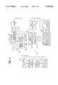
- FIG. 1is a schematic view of a stability sensing unit, which generates an output to assess the stability of an ablation electrode within a targeted body region;
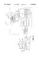
- FIG. 2is a schematic view of the stability sensing functions of the navigation unit shown in FIG. 1;
- FIG. 3is a schematic view of the stability sensing algorithm, which provides an instability output indicating that the ablation electrode is not in stable contact with heart tissue;
- FIG. 4is a schematic view of a graphical user interface for displaying the instability output.
- FIG. 1shows a system 10, which embodies features of the invention.
- the system 10is well adapted for use inside body lumens, chambers or cavities for either diagnostic or therapeutic purposes. For this reason, the system 10 will be described in the context of its use within a living body.
- the system 10particularly lends itself to catheter-based procedures, where access to the interior body region is obtained, for example, through the vascular system or alimentary canal, without complex, invasive surgical procedures.
- the system 10can be used during the diagnosis and treatment of arrhythmia conditions within the heart, such as ventricular tachycardia or atrial fibrillation.
- the system 10also can be used during the diagnosis or treatment of intravascular ailments, in association, for example, with angioplasty or atherectomy techniques.
- the system 10also can be used during the diagnosis or treatment of ailments in the gastrointestinal tract, the prostrate, brain, gall bladder, uterus, and other regions of the body.
- FIG. 1shows the system 10 in the context of ablating heart tissue during the diagnosis and treatment of arrhythmia conditions within the heart, such as ventricular tachycardia or atrial fibrillation.
- the system 10senses the stability, during use, of an operative element deployed within the body.
- the operative elementtakes the form of an ablation electrode.
- the operative elementcan take different forms and can be used for either therapeutic purposes, or diagnostic purposes, or both.
- the operative elementcan comprise, for example, a device for imaging body tissue, such as an ultrasound transducer or an array of ultrasound transducers, or an optic fiber element.
- the operative elementcan comprise a device to deliver a drug or therapeutic material to body tissue.
- the operative elementcan comprise a device, e.g., an electrode, for sensing a physiological characteristic in tissue, such as electrical activity in heart tissue, or, as in the illustrated embodiment, for transmitting energy to stimulate or ablate tissue.
- the system 10includes an ablation instrument 14, which carries an ablation electrode 16.
- the ablation electrode 16is intended to be mobile and capable of roving about the targeted tissue region 12 under the direction of the physician.
- the ablation electrode 16is preferably carried at the distal end of a catheter tube 18.
- the ablation electrode 16is formed from an electrically conductive metal material (e.g., copper alloy, platinum, or stainless steel).
- the ablation electrode 16can comprise a length of wound, spiral coil made of electrically conducting material.
- the ablation electrode 16transmits ablation energy, e.g., in the form of radio-frequency energy, to form a lesion in myocardial tissue.
- the ablation electrode 16can take the form of a cannula to deliver an ablation chemical to heart tissue, or an instrument to deliver an other tissue ablating energy or substance.
- the system 10also includes a stability sensing unit 20, which tracks movement of the ablation electrode 16 relative to a fixed point of reference, and thus its stability, during use.
- a stability sensing unit 20which tracks movement of the ablation electrode 16 relative to a fixed point of reference, and thus its stability, during use.
- the ability to sense relative motion of the electrode 16 during useallows the physician to know when the electrode 16 occupies a stable position before and during ablation, which can lead to more efficacious and consistent lesion formation.
- the stability sensing unit 20includes a stationary tracking probe 22.
- the tracking electrodes TE(i)take the form of conventional rings of electrically conductive material (e.g., copper alloy, platinum, or stainless steel), arranged in a spaced apart, segmented relationship about a sleeve of electrically insulating material.
- the tracking electrodes TE(i)can be coated upon the sleeve using conventional coating techniques or an ion beam assisted deposition (IBAD) process, or comprise spaced apart lengths of wound, spiral coils made of electrically conducting material.
- IBADion beam assisted deposition
- the tracking probe 22can assume different shapes.
- the probe 22can comprise a three dimensional array of electrodes, which assume a basket-like shape, like the CONSTELLATION® Catheter sold by EP Technologies, Inc.
- the tracking probe 22is carried at the distal end of a catheter tube 24 for stationary deployment within or near the heart chamber where ablation is to occur.
- the tracking probe 22may also be positioned in stationary contact with tissue or a vascular region surrounding the ablation area, or may also be positioned in stationary contact with skin on the exterior of the patient's body.
- ATE(1)denotes the most distal tracking electrode on the ablation instrument 14
- ATE(m)denotes the most proximal tracking electrode on the ablation instrument 14.
- m4.
- the tracking electrodes ATE(j)may be components added to the ablation instrument 14 strictly for navigational purposes. Alternatively, the tracking electrodes ATE(j) may comprise components used by the ablation instrument 14 for other purposes, e.g., to sense electrical activity in heart tissue or to pace heart tissue.
- the tracking ATE(j)can be coated upon the sleeve using conventional coating techniques or an ion beam assisted deposition (IBAD) process, or comprise spaced apart lengths of wound, spiral coils made of electrically conducting material.
- IBADion beam assisted deposition
- the stability sensing unit 22includes a signal processing element 26.
- the processing element 26includes an oscillator 28, which is coupled to a host processor 30 by a control bus 32.
- the host processor 30conditions the oscillator 28 to generate an AC wave form at a predetermined amplitude and frequency.
- the signal processing element 26also includes a first electronic switch element or multiplexer 34.
- An address bus 36couples the host processor 30 to the first electronic switch element 34, which is, in turn, coupled to each tracking electrode TE(i) and ATE(j). By commanding the switch element 34, the host processor 30 can distribute the AC output of the oscillator 28 in a prescribed fashion to either one or more tracking electrodes TE(i) or ATE(j).
- the signal processing element 26also includes a data acquisition module 38.
- the data acquisition module 38includes a differential amplifier 40, which is coupled via a second electronic switch element or multiplexer 42 to each tracking electrode TE(i) and ATE(j).
- the host processor 30conditions the second switch element 42 via a second address bus 44 to couple a selected tracking electrode TE(i) or ATE(j) to either the inverting (-) input or noninverting (+) input of the differential amplifier 40.
- the output of the amplifier 40is a differential AC voltage signal 46, which is communicated to the host processor 30 for processing, as will be described later.
- the signal processing element 26can couple the oscillator 28 to any tracking electrode TE(i) or ATE(j) to transmit electrical energy.
- the signal processing element 26can also sense an electrical potential at any tracking electrode TE(i) or ATE(j).
- the data acquisition module 38also includes a synchronized rectifier 48 and a peak detector 50.
- the rectifier 48receives the AC signal voltage output of the amplifier 40 and sense its phase relative to the phase at the output of the oscillator 28.
- the detector 50determines the peak amplitude of the AC voltage signal output of the amplifier 40.
- the output of the detector 50is an analog signal 52 having a value corresponding to the peak amplitude of the AC output of the amplifier 40, and a sign (+ or -) denoting whether the AC voltage output is in phase with the oscillator 28 (+) or out of phase with the oscillator 28 (-).
- the data acquisition module 38registers this analog signal 52 in association with the electrodes then-coupled to the amplifier 40 in a sample and hold element 54.
- An analog to digital converter 56converts the analog signals 52 to digital phase and peak amplitude signals 88 for processing by the host processor.
- a suitable control bus 58couples the components of the data acquisition module 36 to the host processor 30 for coordination and control functions.
- the host processor 30,e.g., sets the sampling rate of the sample and hold element 54, the input range of the converter 56, and the amplification of the amplifier 40.
- the host processor 30is capable of operation in a stability sensing mode. In this mode, the host processor 30 conditions the oscillator 28 to generate an electrical alternating current (AC) waveform at a predetermined amplitude and frequency.
- ACelectrical alternating current
- the selected current amplitude of the oscillator 28 outputcan vary between 0.05 mAmp to about 1.0 mAmp.
- the frequency selectedcan also vary from about 5 kHz to about 100 kHz. Currents substantially above about 5 mAmp and frequencies substantially below 5 kHz should be avoided when heart tissue is nearby, as they pose the danger of inducing fibrillation.
- the maximum current that can be used while avoiding fibrillationis a function of the frequency, as expressed in the following equation:
- Icurrent in ⁇ Amp (RMS)
- ffrequency in kHz.
- the shape of the waveformcan also vary.
- the waveformis sinusoidal.
- square wave shapes or pulsescan also be used, although harmonics may be encountered if capacitive coupling is present.
- the waveformneed not be continuous.
- the oscillator 28may generate pulsed waveforms.
- the host processor 30commands the first switch element 34 to transmit the electrical waveform supplied by the oscillator 28 through a selected one or more tracking electrodes TE(i) on the tracking probe 22.
- An indifferent electrode 60e.g., carried as a patch on the exterior of the patient, comprises the voltage return, which is, in turn, coupled to an electrical reference 62.
- the electrical reference 62is isolated or patient ground, although other references can be used.
- a tracking electrode TE(i) not serving to transmit the electrical waveformcan serve as the voltage return.
- the transmission of electrical energy from the transmitting tracking electrode TE(i) to the indifferent electrode 60establishes a voltage field 64.
- the voltage field 64extends from the transmitting electrode into the targeted tissue region 12.
- the field 64surrounds the ablation instrument 14 present within the region 12.
- the host processor 30conditions the data acquisition module 38 to sense local voltages within the field 64 between the transmitting tracking electrode or electrodes and one of the tracking electrodes ATE(j) on the ablation instrument 14. For example, in a preferred embodiment, the data acquisition module 38 senses voltage amplitudes at the transmitting tracking electrode TE(i) and the other tracking electrode ATE(j).
- the data acquisition module 38can also be conditioned to sense other electrical characteristics in the field 64 in addition to voltage amplitudes. For example, using the rectifier 48 and detector 50, the data acquisition module 38 can acquire spacial variations in phase or spacial variations in waveform within the field. The data acquisition module 38 can also acquire variations in impedances between the transmitting tracking electrode TE(i) and the other tracking electrode ATE(j).
- the host processor 30inputs the electrical field data signals 46 and 88 into a prescribed position sensing algorithm 66, which resides on the host processor 30.
- the algorithm 66includes prescribed functions 68, which processes sensed electrical field data based upon empirically derived mathematical coefficients and weighing factors to generate a position-indicating or navigation output 70.
- the navigation output 70indicates the position of the tracking electrode ATE(j) on the movable ablation instrument 14 relative to the stationary transmitting tracking electrode TE(i) on the tracking probe 22.
- the navigation output 70thereby provides an instantaneous indication of the position of the ablation instrument 14. Over time, the navigation output 70 also indicates change in the position of the ablation instrument 14 within the heart chamber 12, and, therefore, its stability.
- the stability sensing unit 20includes a display device 90 (e.g., a CRT, LED display, or a printer). As will be described in greater detail later, the device 90 presents changes in the navigation output 70 over time in a visual or audio format useful to the physician for ascertaining the stability of the ablation electrode 16.
- a display device 90e.g., a CRT, LED display, or a printer.
- the device 90presents changes in the navigation output 70 over time in a visual or audio format useful to the physician for ascertaining the stability of the ablation electrode 16.
- the technique for acquiring and processing sensed electrical field datacan vary.
- the algorithm 66processes the local amplitude values 46 of the voltage field sensed by the tracking electrode ATE(j) on the ablation instrument 14.
- the local voltage amplitude valuesvary based upon a determinable voltage-to-distance function 72, as the distance between the tracking electrode ATE(j) and the transmitting tracking electrode TE(i) on the probe 22 varies.
- the data acquisition module 38conditions the tracking electrode TE(i) that is currently transmitting the electrical field (which will also be called the "transmitting electrode”) to itself sense a local voltage amplitude, or V TE (i).
- the data acquisition module 38also conditions the tracking electrode ATE(j) on the ablation instrument 14 to sense a local voltage amplitude, or V ATE (j), at the same time V TE (i) is sensed by the tracking electrode TE(i).
- V ATE (j)is acquired in association with each V TE (i).
- V N (i,j)a normalized detected voltage value, designated V N (i,j), for each acquired V TE (i) and V ATE (j) data set, as follows: ##EQU1##
- the normalized detected voltage value V Nis derived by dividing the local voltage amplitude sensed by the transmitting tracking electrode (universally designated V TRANS ) into the local voltage amplitude sensed by the other non-transmitting, sense-only tracking electrode (universally designated V SENSE ), or: ##EQU2##
- the stability sensing unit 20can obtain electrical field data by coupling the oscillator 28 to any tracking electrode ATE(j) on the ablation instrument 14 to generate the electric field between it and the indifferent electrode 60.
- another tracking electrode ATE(j) on the ablation instrument 14 not serving to transmit the energy field, or one of the other tracking electrodes TE(i) on the tracking probe 22,can serve as the voltage return.
- the data acquisition module 38individually conditions a selected tracking electrode TE(i) on the probe 22 (or, in sequence, several tracking electrodes on the probe 22) to sense a local voltage amplitude V TE (i), which corresponds to the quantity V SENSE in Equation (3).
- the data acquisition module 38also conditions the transmitting tracking electrode ATE(j) on the ablation instrument 14 to itself sense a local voltage amplitude V ATE (j) at the same time V TE (i) is sensed by each tracking electrode TE(i) on the probe 22, which corresponds to the quantity V TRANS in Equation (3).
- the navigation output 70can be generated either by sensing using one or more of the tracking electrodes on the ablation instrument 14 or by sensing using one or more of the tracking electrodes on the probe 22.
- the algorithm 66derives a normalized detected voltage value V N (i,j) for each acquired V ATE (j) and V TE (i) data set, as follows: ##EQU3##
- the algorithm 66incorporates a voltage-to-distance function 72, according to which the normalized voltage V N (i.e., V SENSE /V TRANS ) decays to zero as the distance between the sensing electrode (E S ) and the transmitting electrode (E T ) [or d(E S -E T )] increases.
- V Ni.e., V SENSE /V TRANS
- the voltage-to-distance function 72 relating normalized voltage V N to the navigation output d(E S -E T ),can be mathematically expressed, e.g., as follows:
- Equation (5)f is a continuous, monotonically decreasing function.
- the quantities ⁇ 1-to-xare coefficients and weighing factors, which can be determined and assigned values experimentally, e.g., by in vitro or in vivo testing or by finite element analysis.
- the navigation output d(E S -E T )can itself be expressed as a unique inverse function f -1 of the normalized voltage V N , as well as inverse coefficients and weighing factors ⁇ 1-to-n , e.g., as follows:
- Equation (6)The inverse function f -1 of Equation (6) can be approximated using various numeric methods. For example, approximation by Taylor series could be used.
- the navigation algorithm 66Applying the inverse function f -1 based upon sensed electrical conditions in the field, the navigation algorithm 66 generates the navigation output 70, which expresses d(E S -E T ).
- the algorithm 66can apply other empiric functions 74 (see FIG. 2) which include coefficients and weighing factors expressing relationships between distance and the spacial distribution of voltage gradients sensed in the field 64.
- the algorithm 66can include in the generation of the navigation output 70 the application of coefficients and weighing factors relating changes in position to variations in phase sensed in the field, as disclosed in patent application Ser. No. 08/320,301, filed Oct.
- the algorithm 66can also include in the generation of the navigation output 70 the application of coefficients and weighing factors relating changes in position to variations in waveform sensed in the field, as disclosed in copending patent application Ser. No. 08/745,795, filed Nov. 8, 1996, and entitled “Systems and Methods for Locating and Guiding Operating Elements Within Interior Body Regions.” Further discussion of these alternative functions 74 will appear later.
- the predetermined nominal voltage threshold value V THRESHis selected to establish a nominal voltage value variance that is attributable to normal background electrical noise or incidental movement of the ablation instrument 14 due, e.g., to normal heart activity.
- the threshold voltage value V THRESHserves to differentiate between a "stable condition" for the ablation instrument 14 (i.e., when ⁇ V NAVIGATION OUTPUT is equal to or less than the normal voltage variance value) and an "unstable condition" for the ablation instrument 14 (i.e., when ⁇ V NAVIGATION OUTPUT greater than the nominal voltage variance value).
- the physiciancan manipulate the ablation instrument until no instability-indicating output is generated. At that time, the physician can apply ablation energy to the ablation electrode 16 to create a lesion in the adjacent heart tissue.
- the magnitude selected for the threshold value V THRESHsets the spacial criteria for a "stable condition” and an “unstable condition,” given the physical characteristics of the tracking electrodes TE(i) and ATE(j).
- the physical characteristicsinclude the diameter and shape of the electrodes, as well as the electrical conductivity of the material or materials from which the electrodes are made and the electrical properties of the conductive medium existing between the probe 22 and the ablation instrument 14.
- the output display device 90comprises a Graphical User Interface (GUI) 298.
- GUIGraphical User Interface
- the GUI 298is implemented by a graphical control program 200 resident in an external microprocessor based computer control, such as laptap computer 264 having a keyboard 266, a display screen 268, and mouse 270.
- the laptop computer 264is coupled to the host processor 30 via a communication port 272, such as RS 232 or an EthernetTM connection.
- the generation of an instability-indicating output IS by the navigation algorithm 66is transmitted to the control program 200.
- the control program 200switches "ON" the node 280, by changing the designated color or shade.
- the node 280when switched "ON,” displays a different color or shade, e.g., red color, or a graphically “blurred” appearance, to visually signal the physician that the ablation electrode 16 is in an unstable condition.
- the physiciancan then reposition the ablation electrode 16 until the instability-indicating output IS is no longer generated, and the GUI 298 returns the node 280 to its normal default condition.
- GUI 298 and implementing control programscan be implemented using the MS WINDOWSTM application and the standard controls provided by the WINDOWSTM Development Kit, along with conventional graphics software disclosed in public literature.
- Other details of the GUI 298can be found in patent application Ser. No. 08/938,721, filed Sep. 26, 1997, (now abandoned) and entitled "Systems and Methods for Generating Images of Structures Deployed Within Interior Body Regions.”.
Landscapes
- Health & Medical Sciences (AREA)
- Life Sciences & Earth Sciences (AREA)
- Engineering & Computer Science (AREA)
- Surgery (AREA)
- Physics & Mathematics (AREA)
- Veterinary Medicine (AREA)
- Public Health (AREA)
- General Health & Medical Sciences (AREA)
- Biomedical Technology (AREA)
- Heart & Thoracic Surgery (AREA)
- Medical Informatics (AREA)
- Molecular Biology (AREA)
- Animal Behavior & Ethology (AREA)
- Pathology (AREA)
- Biophysics (AREA)
- Human Computer Interaction (AREA)
- Signal Processing (AREA)
- Psychiatry (AREA)
- Computer Vision & Pattern Recognition (AREA)
- Physiology (AREA)
- Artificial Intelligence (AREA)
- Cardiology (AREA)
- Plasma & Fusion (AREA)
- Nuclear Medicine, Radiotherapy & Molecular Imaging (AREA)
- Otolaryngology (AREA)
- Surgical Instruments (AREA)
- Measurement And Recording Of Electrical Phenomena And Electrical Characteristics Of The Living Body (AREA)
Abstract
Description
The invention generally relates to systems and methods for guiding or locating diagnostic or therapeutic elements in interior regions of the body.
Physicians make use of catheters today in medical procedures to gain access into interior regions of the body for diagnostic and therapeutic purposes. It is important for the physician to be able to reliably and precisely position in proximity to desired tissue locations. For example, the need for precise control over the catheter is especially critical during procedures that ablate myocardial tissue from within the heart. These procedures, called ablation therapy, are used to treat cardiac rhythm disturbances. Improved ablation outcomes are achieved when the ablation instrument is maintained in a stable position.
Systems and methods are provided for sensing stability of an ablation instrument inside a body region. The systems and methods position a tracking element in a fixed location spaced from the ablation instrument. The systems and methods generate an output, which varies according to movement of the ablation instrument relative to the tracking element over time.
In a preferred embodiment, the systems and methods visually present the output.
Other features and advantages of the inventions are set forth in the following Description and Drawings, as well as in the appended Claims.
FIG. 1 is a schematic view of a stability sensing unit, which generates an output to assess the stability of an ablation electrode within a targeted body region;
FIG. 2 is a schematic view of the stability sensing functions of the navigation unit shown in FIG. 1;
FIG. 3 is a schematic view of the stability sensing algorithm, which provides an instability output indicating that the ablation electrode is not in stable contact with heart tissue; and
FIG. 4 is a schematic view of a graphical user interface for displaying the instability output.
The invention may be embodied in several forms without departing from its spirit or essential characteristics. The scope of the invention is defined in the appended claims, rather than in the specific description preceding them. All embodiments that fall within the meaning and range of equivalency of the claims are therefore intended to be embraced by the claims.
FIG. 1 shows asystem 10, which embodies features of the invention. Thesystem 10 is well adapted for use inside body lumens, chambers or cavities for either diagnostic or therapeutic purposes. For this reason, thesystem 10 will be described in the context of its use within a living body. Thesystem 10 particularly lends itself to catheter-based procedures, where access to the interior body region is obtained, for example, through the vascular system or alimentary canal, without complex, invasive surgical procedures.
For example, thesystem 10 can be used during the diagnosis and treatment of arrhythmia conditions within the heart, such as ventricular tachycardia or atrial fibrillation. Thesystem 10 also can be used during the diagnosis or treatment of intravascular ailments, in association, for example, with angioplasty or atherectomy techniques. Thesystem 10 also can be used during the diagnosis or treatment of ailments in the gastrointestinal tract, the prostrate, brain, gall bladder, uterus, and other regions of the body.
For purpose of illustration, FIG. 1 shows thesystem 10 in the context of ablating heart tissue during the diagnosis and treatment of arrhythmia conditions within the heart, such as ventricular tachycardia or atrial fibrillation.
Thesystem 10 senses the stability, during use, of an operative element deployed within the body. For the purpose of illustration, the operative element takes the form of an ablation electrode. However, the operative element can take different forms and can be used for either therapeutic purposes, or diagnostic purposes, or both. The operative element can comprise, for example, a device for imaging body tissue, such as an ultrasound transducer or an array of ultrasound transducers, or an optic fiber element.
Alternatively, the operative element can comprise a device to deliver a drug or therapeutic material to body tissue. Still alternatively, the operative element can comprise a device, e.g., an electrode, for sensing a physiological characteristic in tissue, such as electrical activity in heart tissue, or, as in the illustrated embodiment, for transmitting energy to stimulate or ablate tissue.
A. The Roving Ablation Element
Thesystem 10 includes anablation instrument 14, which carries anablation electrode 16. Theablation electrode 16 is intended to be mobile and capable of roving about the targetedtissue region 12 under the direction of the physician. For roving deployment in the targetedtissue region 12, theablation electrode 16 is preferably carried at the distal end of acatheter tube 18.
In the illustrated embodiment, theablation electrode 16 is formed from an electrically conductive metal material (e.g., copper alloy, platinum, or stainless steel). Alternatively, theablation electrode 16 can comprise a length of wound, spiral coil made of electrically conducting material. In use, theablation electrode 16 transmits ablation energy, e.g., in the form of radio-frequency energy, to form a lesion in myocardial tissue.
Alternatively, theablation electrode 16 can take the form of a cannula to deliver an ablation chemical to heart tissue, or an instrument to deliver an other tissue ablating energy or substance.
B. The Stability Sensing Unit
Thesystem 10 also includes astability sensing unit 20, which tracks movement of theablation electrode 16 relative to a fixed point of reference, and thus its stability, during use. The ability to sense relative motion of theelectrode 16 during use allows the physician to know when theelectrode 16 occupies a stable position before and during ablation, which can lead to more efficacious and consistent lesion formation.
1. The Tracking Probe
Thestability sensing unit 20 includes astationary tracking probe 22. In the illustrated embodiment, thetracking probe 22 takes the form of an elongated array of tracking electrodes NE(i), where i=1 to n, and where TE(1) denotes the most distal tracking electrode and TE(n) denotes the most proximal tracking electrode. In the illustrated embodiment, n=5.
In the illustrated embodiment, the tracking electrodes TE(i) take the form of conventional rings of electrically conductive material (e.g., copper alloy, platinum, or stainless steel), arranged in a spaced apart, segmented relationship about a sleeve of electrically insulating material. Alternatively, the tracking electrodes TE(i) can be coated upon the sleeve using conventional coating techniques or an ion beam assisted deposition (IBAD) process, or comprise spaced apart lengths of wound, spiral coils made of electrically conducting material.
Thetracking probe 22 can assume different shapes. For example, theprobe 22 can comprise a three dimensional array of electrodes, which assume a basket-like shape, like the CONSTELLATION® Catheter sold by EP Technologies, Inc.
In the illustrated embodiment, thetracking probe 22 is carried at the distal end of acatheter tube 24 for stationary deployment within or near the heart chamber where ablation is to occur. Thetracking probe 22 may also be positioned in stationary contact with tissue or a vascular region surrounding the ablation area, or may also be positioned in stationary contact with skin on the exterior of the patient's body.
Thestability sensing unit 20 also includes at least one tracking electrode ATE(j) on themovable ablation instrument 14, where j=2 to m, and where ATE(1) denotes the most distal tracking electrode on theablation instrument 14 and ATE(m) denotes the most proximal tracking electrode on theablation instrument 14. In the illustrated embodiment, m=4.
The tracking electrodes ATE(j) may be components added to theablation instrument 14 strictly for navigational purposes. Alternatively, the tracking electrodes ATE(j) may comprise components used by theablation instrument 14 for other purposes, e.g., to sense electrical activity in heart tissue or to pace heart tissue.
In the illustrated embodiment, the tracking electrodes ATE(j) on theablation instrument 14, like tracking electrodes TE(i) on thetracking probe 22, take the form of conventional rings of electrically conductive material (e.g., copper alloy, platinum, or stainless steel), arranged in a spaced apart, segmented relationship about a sleeve of electrically insulating material. Alternatively, like the tracking electrodes TE(i), the tracking ATE(j) can be coated upon the sleeve using conventional coating techniques or an ion beam assisted deposition (IBAD) process, or comprise spaced apart lengths of wound, spiral coils made of electrically conducting material.
2. The Signal Processing Element
Still referring to FIG. 1, thestability sensing unit 22 includes asignal processing element 26. Theprocessing element 26 includes anoscillator 28, which is coupled to ahost processor 30 by acontrol bus 32. Thehost processor 30 conditions theoscillator 28 to generate an AC wave form at a predetermined amplitude and frequency.
Thesignal processing element 26 also includes a first electronic switch element ormultiplexer 34. An address bus 36 couples thehost processor 30 to the firstelectronic switch element 34, which is, in turn, coupled to each tracking electrode TE(i) and ATE(j). By commanding theswitch element 34, thehost processor 30 can distribute the AC output of theoscillator 28 in a prescribed fashion to either one or more tracking electrodes TE(i) or ATE(j).
Thesignal processing element 26 also includes adata acquisition module 38. Thedata acquisition module 38 includes adifferential amplifier 40, which is coupled via a second electronic switch element ormultiplexer 42 to each tracking electrode TE(i) and ATE(j). Thehost processor 30 conditions thesecond switch element 42 via asecond address bus 44 to couple a selected tracking electrode TE(i) or ATE(j) to either the inverting (-) input or noninverting (+) input of thedifferential amplifier 40.
The output of theamplifier 40 is a differentialAC voltage signal 46, which is communicated to thehost processor 30 for processing, as will be described later.
In this arrangement, thesignal processing element 26 can couple theoscillator 28 to any tracking electrode TE(i) or ATE(j) to transmit electrical energy. Thesignal processing element 26 can also sense an electrical potential at any tracking electrode TE(i) or ATE(j).
In the illustrated embodiment (see FIG. 1), thedata acquisition module 38 also includes asynchronized rectifier 48 and apeak detector 50. Therectifier 48 receives the AC signal voltage output of theamplifier 40 and sense its phase relative to the phase at the output of theoscillator 28. Thedetector 50 determines the peak amplitude of the AC voltage signal output of theamplifier 40.
The output of thedetector 50 is ananalog signal 52 having a value corresponding to the peak amplitude of the AC output of theamplifier 40, and a sign (+ or -) denoting whether the AC voltage output is in phase with the oscillator 28 (+) or out of phase with the oscillator 28 (-).
Thedata acquisition module 38 registers thisanalog signal 52 in association with the electrodes then-coupled to theamplifier 40 in a sample and holdelement 54. An analog todigital converter 56 converts the analog signals 52 to digital phase and peak amplitude signals 88 for processing by the host processor.
Asuitable control bus 58 couples the components of the data acquisition module 36 to thehost processor 30 for coordination and control functions. Thehost processor 30, e.g., sets the sampling rate of the sample and holdelement 54, the input range of theconverter 56, and the amplification of theamplifier 40.
A. Generating a Position-Indicating Output
In the illustrated embodiment (FIG. 1), thehost processor 30 is capable of operation in a stability sensing mode. In this mode, thehost processor 30 conditions theoscillator 28 to generate an electrical alternating current (AC) waveform at a predetermined amplitude and frequency.
For use within a living body space, the selected current amplitude of theoscillator 28 output can vary between 0.05 mAmp to about 1.0 mAmp. The frequency selected can also vary from about 5 kHz to about 100 kHz. Currents substantially above about 5 mAmp and frequencies substantially below 5 kHz should be avoided when heart tissue is nearby, as they pose the danger of inducing fibrillation. The maximum current that can be used while avoiding fibrillation is a function of the frequency, as expressed in the following equation:
I=f×10 (1)
where I is current in μAmp (RMS), and f is frequency in kHz.
The shape of the waveform can also vary. In the illustrated and preferred embodiment, the waveform is sinusoidal. However, square wave shapes or pulses can also be used, although harmonics may be encountered if capacitive coupling is present. Furthermore, the waveform need not be continuous. Theoscillator 28 may generate pulsed waveforms.
Thehost processor 30 commands thefirst switch element 34 to transmit the electrical waveform supplied by theoscillator 28 through a selected one or more tracking electrodes TE(i) on thetracking probe 22. Anindifferent electrode 60, e.g., carried as a patch on the exterior of the patient, comprises the voltage return, which is, in turn, coupled to anelectrical reference 62. In the illustrated embodiment, theelectrical reference 62 is isolated or patient ground, although other references can be used. Alternatively, a tracking electrode TE(i) not serving to transmit the electrical waveform can serve as the voltage return.
The transmission of electrical energy from the transmitting tracking electrode TE(i) to theindifferent electrode 60 establishes avoltage field 64. Thevoltage field 64 extends from the transmitting electrode into the targetedtissue region 12. Thefield 64 surrounds theablation instrument 14 present within theregion 12.
Thehost processor 30 conditions thedata acquisition module 38 to sense local voltages within thefield 64 between the transmitting tracking electrode or electrodes and one of the tracking electrodes ATE(j) on theablation instrument 14. For example, in a preferred embodiment, thedata acquisition module 38 senses voltage amplitudes at the transmitting tracking electrode TE(i) and the other tracking electrode ATE(j).
Thedata acquisition module 38 can also be conditioned to sense other electrical characteristics in thefield 64 in addition to voltage amplitudes. For example, using therectifier 48 anddetector 50, thedata acquisition module 38 can acquire spacial variations in phase or spacial variations in waveform within the field. Thedata acquisition module 38 can also acquire variations in impedances between the transmitting tracking electrode TE(i) and the other tracking electrode ATE(j).
Thehost processor 30 inputs the electrical field data signals 46 and 88 into a prescribedposition sensing algorithm 66, which resides on thehost processor 30. Thealgorithm 66 includes prescribedfunctions 68, which processes sensed electrical field data based upon empirically derived mathematical coefficients and weighing factors to generate a position-indicating ornavigation output 70. Thenavigation output 70 indicates the position of the tracking electrode ATE(j) on themovable ablation instrument 14 relative to the stationary transmitting tracking electrode TE(i) on thetracking probe 22. Thenavigation output 70 thereby provides an instantaneous indication of the position of theablation instrument 14. Over time, thenavigation output 70 also indicates change in the position of theablation instrument 14 within theheart chamber 12, and, therefore, its stability.
In the illustrated embodiment (FIG. 1), thestability sensing unit 20 includes a display device 90 (e.g., a CRT, LED display, or a printer). As will be described in greater detail later, thedevice 90 presents changes in thenavigation output 70 over time in a visual or audio format useful to the physician for ascertaining the stability of theablation electrode 16.
The technique for acquiring and processing sensed electrical field data can vary. In a preferred embodiment (see FIG. 2), thealgorithm 66 processes the local amplitude values 46 of the voltage field sensed by the tracking electrode ATE(j) on theablation instrument 14. The local voltage amplitude values vary based upon a determinable voltage-to-distance function 72, as the distance between the tracking electrode ATE(j) and the transmitting tracking electrode TE(i) on theprobe 22 varies.
To acquire voltage amplitude data, thedata acquisition module 38 conditions the tracking electrode TE(i) that is currently transmitting the electrical field (which will also be called the "transmitting electrode") to itself sense a local voltage amplitude, or VTE(i). Thedata acquisition module 38 also conditions the tracking electrode ATE(j) on theablation instrument 14 to sense a local voltage amplitude, or VATE(j), at the same time VTE(i) is sensed by the tracking electrode TE(i). VATE(j) is acquired in association with each VTE(i).
Based upon this input, thealgorithm 66 derives a normalized detected voltage value, designated VN(i,j), for each acquired VTE(i) and VATE(j) data set, as follows: ##EQU1##
More universally expressed, the normalized detected voltage value VN is derived by dividing the local voltage amplitude sensed by the transmitting tracking electrode (universally designated VTRANS) into the local voltage amplitude sensed by the other non-transmitting, sense-only tracking electrode (universally designated VSENSE), or: ##EQU2##
Applying this more universal expression, thestability sensing unit 20 can obtain electrical field data by coupling theoscillator 28 to any tracking electrode ATE(j) on theablation instrument 14 to generate the electric field between it and theindifferent electrode 60. Alternatively, another tracking electrode ATE(j) on theablation instrument 14 not serving to transmit the energy field, or one of the other tracking electrodes TE(i) on thetracking probe 22, can serve as the voltage return. In this alternative implementation, thedata acquisition module 38 individually conditions a selected tracking electrode TE(i) on the probe 22 (or, in sequence, several tracking electrodes on the probe 22) to sense a local voltage amplitude VTE(i), which corresponds to the quantity VSENSE in Equation (3). Thedata acquisition module 38 also conditions the transmitting tracking electrode ATE(j) on theablation instrument 14 to itself sense a local voltage amplitude VATE(j) at the same time VTE(i) is sensed by each tracking electrode TE(i) on theprobe 22, which corresponds to the quantity VTRANS in Equation (3).
As the foregoing discussion demonstrates, thenavigation output 70 can be generated either by sensing using one or more of the tracking electrodes on theablation instrument 14 or by sensing using one or more of the tracking electrodes on theprobe 22.
In this arrangement, thealgorithm 66 derives a normalized detected voltage value VN(i,j) for each acquired VATE(j) and VTE(i) data set, as follows: ##EQU3##
The algorithm 66 (see FIG. 2) incorporates a voltage-to-distance function 72, according to which the normalized voltage VN (i.e., VSENSE /VTRANS) decays to zero as the distance between the sensing electrode (ES) and the transmitting electrode (ET) [or d(ES -ET)] increases.
The voltage-to-distance function 72 relating normalized voltage VN to the navigation output d(ES -ET), can be mathematically expressed, e.g., as follows:
V.sub.n =f(λ.sub.1, λ.sub.2, . . . , λ.sub.x d(E.sub.S -E.sub.T)) (5)
In Equation (5), f is a continuous, monotonically decreasing function. The quantities λ1-to-x are coefficients and weighing factors, which can be determined and assigned values experimentally, e.g., by in vitro or in vivo testing or by finite element analysis.
Because the function f is continuous and monotone, the navigation output d(ES -ET) can itself be expressed as a unique inverse function f-1 of the normalized voltage VN, as well as inverse coefficients and weighing factors λ1-to-n, e.g., as follows:
d(E.sub.S -E.sub.T)=f.sup.-1 (λ.sub.1, λ.sub.2, . . . , λ.sub.y, V.sub.N) (6)
The inverse function f-1 of Equation (6) can be approximated using various numeric methods. For example, approximation by Taylor series could be used.
Applying the inverse function f-1 based upon sensed electrical conditions in the field, thenavigation algorithm 66 generates thenavigation output 70, which expresses d(ES -ET).
In addition to the empiric voltage-to-distance function 72, thealgorithm 66 can apply other empiric functions 74 (see FIG. 2) which include coefficients and weighing factors expressing relationships between distance and the spacial distribution of voltage gradients sensed in thefield 64. For example, thealgorithm 66 can include in the generation of thenavigation output 70 the application of coefficients and weighing factors relating changes in position to variations in phase sensed in the field, as disclosed in patent application Ser. No. 08/320,301, filed Oct. 11, 1994, (now abandoned) and entitled "Systems and Methods for Guiding Movable Electrode Elements Within Multiple Electrode Structures." As another example, thealgorithm 66 can also include in the generation of thenavigation output 70 the application of coefficients and weighing factors relating changes in position to variations in waveform sensed in the field, as disclosed in copending patent application Ser. No. 08/745,795, filed Nov. 8, 1996, and entitled "Systems and Methods for Locating and Guiding Operating Elements Within Interior Body Regions." Further discussion of these alternative functions 74 will appear later.
B. Generating a Stability Output
The coefficients λ1-tp-y convert the normalized voltage amplitude to periodically express the position-indication output 70 as a voltage value (VNAVIGATION OUTPUT). Thestability sensing unit 20 derives a change in thenavigation output 70 over time (ΔVNAVIGATION OUTPUT), expressed as a voltage value, over successive time periods. Referring to FIG. 3, thestability sensing unit 20 includes acomparator 92, which receives as input the voltage value ΔVNAVIGATION OUTPUT for each time period. The comparator also receives as input aset line voltage 94, which constitutes a predetermined nominal voltage threshold value VTHRESH. Thecomparator 92 compares the magnitude of voltage value ΔVNAVIGATION OUTPUT to the magnitude of VTHRESH.
The predetermined nominal voltage threshold value VTHRESH is selected to establish a nominal voltage value variance that is attributable to normal background electrical noise or incidental movement of theablation instrument 14 due, e.g., to normal heart activity. The threshold voltage value VTHRESH serves to differentiate between a "stable condition" for the ablation instrument 14 (i.e., when ΔVNAVIGATION OUTPUT is equal to or less than the normal voltage variance value) and an "unstable condition" for the ablation instrument 14 (i.e., when ΔVNAVIGATION OUTPUT greater than the nominal voltage variance value).
If ΔVNAVIGATION OUTPUT is greater than VTHRESH, the comparator generates an instability-indicating output, also designed IS for theablation instrument 14. The instability-indicated output IS notifies the physician that theablation instrument 14 is not stable enough to generate an efficacious lesion.
When ΔVNAVIGATION OUTPUT is equal to or less than VTHRESH, the comparator generates no output. The absence of an instability-indicating output IS notifies the physician that the requisite stability exists for efficacious lesion formation.
Aided by the instability=indicating output IS, the physician can manipulate the ablation instrument until no instability-indicating output is generated. At that time, the physician can apply ablation energy to theablation electrode 16 to create a lesion in the adjacent heart tissue.
The magnitude selected for the threshold value VTHRESH sets the spacial criteria for a "stable condition" and an "unstable condition," given the physical characteristics of the tracking electrodes TE(i) and ATE(j). The physical characteristics include the diameter and shape of the electrodes, as well as the electrical conductivity of the material or materials from which the electrodes are made and the electrical properties of the conductive medium existing between theprobe 22 and theablation instrument 14.
The value of VTHRESH can be set at a desired fixed voltage value representing a nominal threshold distance. In the illustrated and preferred embodiment (see FIG. 3), thenavigation unit 20 includes aninput 96 by which the physician can designate a value for the nominal voltage variance. Thenavigation unit 20 also includes avoltage regulator 98, which sets thevoltage line input 94 to the normalized voltage variance value (VTHRESH), to thereby achieve the spacial sensitivity established by the physician or the instability-indicating output IS.
C. Displaying the Stability Output
As before described, thesystem 10 includes anoutput display device 90, which presents changes in thenavigation output 70 over time in a format useful to the physician for ascertaining the stability of theablation electrode 16. The format display of thedevice 90 may present thenavigation output 70 in various ways.
In the embodiment shown in FIG. 4, theoutput display device 90 comprises a Graphical User Interface (GUI) 298. In the illustrated embodiment, theGUI 298 is implemented by agraphical control program 200 resident in an external microprocessor based computer control, such aslaptap computer 264 having akeyboard 266, adisplay screen 268, andmouse 270. Thelaptop computer 264 is coupled to thehost processor 30 via acommunication port 272, such as RS 232 or an Ethernet™ connection.
Thehost processor 30 conditions the GUIgraphical control program 200 to generate on thedisplay screen 268 an idealizedgraphical image 274, which models the geometry of the particularroving ablation element 14 deployed in the body region. Theimage 274 of theablation element 14 can appear, e.g., as a modeled wire-frame image, with theablation electrode 16 appearing as anode 280.
TheGUI control program 200 initializes thenode 280 on themodel image 274 at a designated color or shade. The initialized color or shade for thenode 280 constitutes a default visual signal to the physician, that theablation electrode 16 is in a stable condition.
The generation of an instability-indicating output IS by thenavigation algorithm 66 is transmitted to thecontrol program 200. Thecontrol program 200 switches "ON" thenode 280, by changing the designated color or shade. Thenode 280, when switched "ON," displays a different color or shade, e.g., red color, or a graphically "blurred" appearance, to visually signal the physician that theablation electrode 16 is in an unstable condition. The physician can then reposition theablation electrode 16 until the instability-indicating output IS is no longer generated, and theGUI 298 returns thenode 280 to its normal default condition.
The foregoingGUI 298 and implementing control programs can be implemented using the MS WINDOWS™ application and the standard controls provided by the WINDOWS™ Development Kit, along with conventional graphics software disclosed in public literature. Other details of theGUI 298 can be found in patent application Ser. No. 08/938,721, filed Sep. 26, 1997, (now abandoned) and entitled "Systems and Methods for Generating Images of Structures Deployed Within Interior Body Regions.".
Various features of the invention are set forth in the following claims.
Claims (4)
1. A system for sensing stability of an operative instrument inside a body region, comprising:
a stationary tracking element spaced from the operative instrument,
a signal processing element coupled to the stationary tracking element and the operative instrument to generate an output voltage value indicative of movement of the operative instrument relative to the stationary tracking element over time, and
a comparator that compares the output voltage value with a threshold voltage value and generates an instability-indicated output based on the comparison, wherein the threshold voltage value differentiates between a stable condition and an unstable condition.
2. A system according to claim 1, further including a display device for presenting the instability-indicated output.
3. A method of sensing stability of an operative instrument inside a body region, comprising:
positioning a tracking element in a fixed location spaced from the operative instrument,
generating an output voltage indicative of movement of the operative instrument relative to the stationary tracking element over time, and
comparing the output voltage value with a threshold voltage value and generating an instability-indicated output based on the comparison, wherein the threshold voltage value differentiates between a stable condition and an unstable condition.
4. A method according to claim 3, further including visually presenting the instability-indicated output.
Priority Applications (1)
| Application Number | Priority Date | Filing Date | Title |
|---|---|---|---|
| US09/083,712US6129669A (en) | 1998-05-22 | 1998-05-22 | Systems and methods for assessing stability of an ablation electrode in contact with heart tissue |
Applications Claiming Priority (1)
| Application Number | Priority Date | Filing Date | Title |
|---|---|---|---|
| US09/083,712US6129669A (en) | 1998-05-22 | 1998-05-22 | Systems and methods for assessing stability of an ablation electrode in contact with heart tissue |
Publications (1)
| Publication Number | Publication Date |
|---|---|
| US6129669Atrue US6129669A (en) | 2000-10-10 |
Family
ID=22180195
Family Applications (1)
| Application Number | Title | Priority Date | Filing Date |
|---|---|---|---|
| US09/083,712Expired - LifetimeUS6129669A (en) | 1998-05-22 | 1998-05-22 | Systems and methods for assessing stability of an ablation electrode in contact with heart tissue |
Country Status (1)
| Country | Link |
|---|---|
| US (1) | US6129669A (en) |
Cited By (45)
| Publication number | Priority date | Publication date | Assignee | Title |
|---|---|---|---|---|
| US20020058870A1 (en)* | 1997-03-07 | 2002-05-16 | Ep Technologies, Inc. | Systems and methods for assessing stability of an operative instrument in a body region |
| US20050149060A1 (en)* | 2003-06-26 | 2005-07-07 | Thorstenson Chad A. | Splittable cannula having radiopaque marker |
| US20060173251A1 (en)* | 2005-01-07 | 2006-08-03 | Assaf Govari | Current-based position sensing |
| US20080161681A1 (en)* | 2006-12-29 | 2008-07-03 | Hauck John A | Navigational reference dislodgement detection method & system |
| US20080275465A1 (en)* | 2005-12-06 | 2008-11-06 | Saurav Paul | Design of Handle Set for Ablation Catheter with Indicators of Catheter and Tissue Parameters |
| US20090163904A1 (en)* | 2005-12-06 | 2009-06-25 | St. Jude Medical, Atrial Fibrillation Division, Inc. | System and Method for Assessing Coupling Between an Electrode and Tissue |
| US20090177111A1 (en)* | 2006-12-06 | 2009-07-09 | Miller Stephan P | System and method for displaying contact between a catheter and tissue |
| US20090275827A1 (en)* | 2005-12-06 | 2009-11-05 | Aiken Robert D | System and method for assessing the proximity of an electrode to tissue in a body |
| US20100069921A1 (en)* | 2006-12-06 | 2010-03-18 | Miller Stephan P | System and method for assessing lesions in tissue |
| US20100168735A1 (en)* | 2005-12-06 | 2010-07-01 | Don Curtis Deno | System and method for assessing coupling between an electrode and tissue |
| US20100286690A1 (en)* | 2005-12-06 | 2010-11-11 | Saurav Paul | Assessment of electrode coupling for tissue ablation |
| US20100298823A1 (en)* | 2005-12-06 | 2010-11-25 | Hong Cao | Assessment of electrode coupling for tissue ablation |
| US20110118727A1 (en)* | 2005-12-06 | 2011-05-19 | Fish Jeffrey M | System and method for assessing the formation of a lesion in tissue |
| CN103732162A (en)* | 2011-08-09 | 2014-04-16 | 皇家飞利浦有限公司 | Displacement feedback device and method for sensing or therapy delivery probes |
| US20140364715A1 (en)* | 2013-06-11 | 2014-12-11 | St.Jude Medical, Atrial Fibrillation Division,Inc. | Multi-electrode impedance sensing |
| US9204927B2 (en) | 2009-05-13 | 2015-12-08 | St. Jude Medical, Atrial Fibrillation Division, Inc. | System and method for presenting information representative of lesion formation in tissue during an ablation procedure |
| US9254163B2 (en) | 2005-12-06 | 2016-02-09 | St. Jude Medical, Atrial Fibrillation Division, Inc. | Assessment of electrode coupling for tissue ablation |
| US9320570B2 (en) | 2007-12-28 | 2016-04-26 | St. Jude Medical, Atrial Fibrillation Division, Inc. | System and method for preventing collateral damage with interventional medical procedures |
| US9492226B2 (en) | 2005-12-06 | 2016-11-15 | St. Jude Medical, Atrial Fibrillation Division, Inc. | Graphical user interface for real-time RF lesion depth display |
| US9510905B2 (en) | 2014-11-19 | 2016-12-06 | Advanced Cardiac Therapeutics, Inc. | Systems and methods for high-resolution mapping of tissue |
| US9517103B2 (en) | 2014-11-19 | 2016-12-13 | Advanced Cardiac Therapeutics, Inc. | Medical instruments with multiple temperature sensors |
| US9532725B2 (en) | 2014-03-07 | 2017-01-03 | Boston Scientific Scimed Inc. | Medical devices for mapping cardiac tissue |
| US9585586B2 (en) | 2006-12-29 | 2017-03-07 | St. Jude Medical, Atrial Fibrillation Division, Inc. | Navigational reference dislodgement detection method and system |
| US9636164B2 (en) | 2015-03-25 | 2017-05-02 | Advanced Cardiac Therapeutics, Inc. | Contact sensing systems and methods |
| US9687167B2 (en) | 2014-03-11 | 2017-06-27 | Boston Scientific Scimed, Inc. | Medical devices for mapping cardiac tissue |
| US9730600B2 (en) | 2013-10-31 | 2017-08-15 | Boston Scientific Scimed, Inc. | Medical device for high resolution mapping using localized matching |
| US9820695B2 (en) | 2010-03-29 | 2017-11-21 | St. Jude Medical International Holding S.àr.l. | Method for detecting contact with the wall of a region of interest |
| US9993178B2 (en) | 2016-03-15 | 2018-06-12 | Epix Therapeutics, Inc. | Methods of determining catheter orientation |
| EP2445434B1 (en)* | 2009-12-11 | 2018-08-22 | St. Jude Medical Atrial Fibrillation Division, Inc. | System for determining the likelihood of endocardial barotrauma in tissue during ablation |
| US10076258B2 (en) | 2013-11-01 | 2018-09-18 | Boston Scientific Scimed, Inc. | Cardiac mapping using latency interpolation |
| US10096105B2 (en) | 2016-09-08 | 2018-10-09 | Medtronic Cryocath Lp | Method of determining target treatment locations |
| US10166062B2 (en) | 2014-11-19 | 2019-01-01 | Epix Therapeutics, Inc. | High-resolution mapping of tissue with pacing |
| DE102004052166B4 (en) | 2003-10-31 | 2019-03-28 | Medtronic, Inc. | An improved display device for use with an implantable medical device |
| DE102004052165B4 (en) | 2003-10-31 | 2019-04-11 | Medtronic, Inc. | Electronic valve reader |
| US10327859B2 (en) | 2015-09-21 | 2019-06-25 | Biosense Webster (Israel) Ltd. | Catheter stability indication |
| US10555685B2 (en) | 2007-12-28 | 2020-02-11 | St. Jude Medical, Atrial Fibrillation Division, Inc. | Method and apparatus for determining tissue morphology based on phase angle |
| US10702342B2 (en) | 2016-09-08 | 2020-07-07 | Medtronic, Inc. | Navigation guidance method for complex catheters |
| US10750974B2 (en) | 2017-10-24 | 2020-08-25 | St. Jude Medical, Cardiology Division, Inc. | System for measuring impedance between a plurality of electrodes of a medical device |
| US10888373B2 (en) | 2017-04-27 | 2021-01-12 | Epix Therapeutics, Inc. | Contact assessment between an ablation catheter and tissue |
| US11172991B2 (en) | 2016-09-08 | 2021-11-16 | Medtronic, Inc. | Navigation with arbitrary catheter geometries and method of contact assessment |
| US11331140B2 (en) | 2016-05-19 | 2022-05-17 | Aqua Heart, Inc. | Heated vapor ablation systems and methods for treating cardiac conditions |
| US11589920B2 (en) | 2008-10-06 | 2023-02-28 | Santa Anna Tech Llc | Catheter with a double balloon structure to generate and apply an ablative zone to tissue |
| US11612334B2 (en) | 2017-12-19 | 2023-03-28 | St. Jude Medical, Cardiology Division, Inc. | Methods of assessing contact between an electrode and tissue using complex impedance measurements |
| WO2023223131A1 (en) | 2022-05-20 | 2023-11-23 | Biosense Webster (Israel) Ltd. | Visualizing a quality index indicative of ablation stability at ablation site |
| US12364537B2 (en) | 2016-05-02 | 2025-07-22 | Santa Anna Tech Llc | Catheter with a double balloon structure to generate and apply a heated ablative zone to tissue |
Citations (9)
| Publication number | Priority date | Publication date | Assignee | Title |
|---|---|---|---|---|
| US5099845A (en)* | 1989-05-24 | 1992-03-31 | Micronix Pty Ltd. | Medical instrument location means |
| US5577502A (en)* | 1995-04-03 | 1996-11-26 | General Electric Company | Imaging of interventional devices during medical procedures |
| US5598848A (en)* | 1994-03-31 | 1997-02-04 | Ep Technologies, Inc. | Systems and methods for positioning multiple electrode structures in electrical contact with the myocardium |
| US5697377A (en)* | 1995-11-22 | 1997-12-16 | Medtronic, Inc. | Catheter mapping system and method |
| US5740808A (en)* | 1996-10-28 | 1998-04-21 | Ep Technologies, Inc | Systems and methods for guilding diagnostic or therapeutic devices in interior tissue regions |
| US5868673A (en)* | 1995-03-28 | 1999-02-09 | Sonometrics Corporation | System for carrying out surgery, biopsy and ablation of a tumor or other physical anomaly |
| US5876336A (en)* | 1994-10-11 | 1999-03-02 | Ep Technologies, Inc. | Systems and methods for guiding movable electrode elements within multiple-electrode structure |
| US5899860A (en)* | 1996-09-12 | 1999-05-04 | Siemens Elema Ab | Method and device for determining the position of a catheter inside the body of a patient |
| US6035226A (en)* | 1998-05-22 | 2000-03-07 | Scimed Life Systems, Inc. | Systems and methods for assessing stability of an operative instrument inside a body region |
- 1998
- 1998-05-22USUS09/083,712patent/US6129669A/ennot_activeExpired - Lifetime
Patent Citations (9)
| Publication number | Priority date | Publication date | Assignee | Title |
|---|---|---|---|---|
| US5099845A (en)* | 1989-05-24 | 1992-03-31 | Micronix Pty Ltd. | Medical instrument location means |
| US5598848A (en)* | 1994-03-31 | 1997-02-04 | Ep Technologies, Inc. | Systems and methods for positioning multiple electrode structures in electrical contact with the myocardium |
| US5876336A (en)* | 1994-10-11 | 1999-03-02 | Ep Technologies, Inc. | Systems and methods for guiding movable electrode elements within multiple-electrode structure |
| US5868673A (en)* | 1995-03-28 | 1999-02-09 | Sonometrics Corporation | System for carrying out surgery, biopsy and ablation of a tumor or other physical anomaly |
| US5577502A (en)* | 1995-04-03 | 1996-11-26 | General Electric Company | Imaging of interventional devices during medical procedures |
| US5697377A (en)* | 1995-11-22 | 1997-12-16 | Medtronic, Inc. | Catheter mapping system and method |
| US5899860A (en)* | 1996-09-12 | 1999-05-04 | Siemens Elema Ab | Method and device for determining the position of a catheter inside the body of a patient |
| US5740808A (en)* | 1996-10-28 | 1998-04-21 | Ep Technologies, Inc | Systems and methods for guilding diagnostic or therapeutic devices in interior tissue regions |
| US6035226A (en)* | 1998-05-22 | 2000-03-07 | Scimed Life Systems, Inc. | Systems and methods for assessing stability of an operative instrument inside a body region |
Cited By (110)
| Publication number | Priority date | Publication date | Assignee | Title |
|---|---|---|---|---|
| US20020058870A1 (en)* | 1997-03-07 | 2002-05-16 | Ep Technologies, Inc. | Systems and methods for assessing stability of an operative instrument in a body region |
| US20050149060A1 (en)* | 2003-06-26 | 2005-07-07 | Thorstenson Chad A. | Splittable cannula having radiopaque marker |
| US7879024B2 (en) | 2003-06-26 | 2011-02-01 | St. Jude Medical, Atrial Fibrillation Division, Inc. | Splittable cannula having radiopaque marker |
| DE102004052166B4 (en) | 2003-10-31 | 2019-03-28 | Medtronic, Inc. | An improved display device for use with an implantable medical device |
| DE102004052165B4 (en) | 2003-10-31 | 2019-04-11 | Medtronic, Inc. | Electronic valve reader |
| US7869865B2 (en)* | 2005-01-07 | 2011-01-11 | Biosense Webster, Inc. | Current-based position sensing |
| US20060173251A1 (en)* | 2005-01-07 | 2006-08-03 | Assaf Govari | Current-based position sensing |
| US8755860B2 (en) | 2005-12-06 | 2014-06-17 | St. Jude Medical, Atrial Fibrillation Division, Inc. | Method for displaying catheter electrode-tissue contact in electro-anatomic mapping and navigation system |
| US8998890B2 (en)* | 2005-12-06 | 2015-04-07 | St. Jude Medical, Atrial Fibrillation Division, Inc. | Assessment of electrode coupling for tissue ablation |
| US20090275827A1 (en)* | 2005-12-06 | 2009-11-05 | Aiken Robert D | System and method for assessing the proximity of an electrode to tissue in a body |
| US10182860B2 (en) | 2005-12-06 | 2019-01-22 | St. Jude Medical, Atrial Fibrillation Division, Inc. | Assessment of electrode coupling for tissue ablation |
| US20100168735A1 (en)* | 2005-12-06 | 2010-07-01 | Don Curtis Deno | System and method for assessing coupling between an electrode and tissue |
| US20100228247A1 (en)* | 2005-12-06 | 2010-09-09 | Saurav Paul | Assessment of electrode coupling of tissue ablation |
| US20100241117A1 (en)* | 2005-12-06 | 2010-09-23 | Saurav Paul | Assessment of Electrode Coupling for Tissue Ablation |
| US20100286690A1 (en)* | 2005-12-06 | 2010-11-11 | Saurav Paul | Assessment of electrode coupling for tissue ablation |
| US20100298823A1 (en)* | 2005-12-06 | 2010-11-25 | Hong Cao | Assessment of electrode coupling for tissue ablation |
| US20090163904A1 (en)* | 2005-12-06 | 2009-06-25 | St. Jude Medical, Atrial Fibrillation Division, Inc. | System and Method for Assessing Coupling Between an Electrode and Tissue |
| US20080300589A1 (en)* | 2005-12-06 | 2008-12-04 | Saurav Paul | Assessment of Electrode Coupling for Tissue Ablation |
| US20110118727A1 (en)* | 2005-12-06 | 2011-05-19 | Fish Jeffrey M | System and method for assessing the formation of a lesion in tissue |
| US8317783B2 (en)* | 2005-12-06 | 2012-11-27 | St. Jude Medical, Atrial Fibrillation Division, Inc. | Assessment of electrode coupling for tissue ablation |
| US8369922B2 (en) | 2005-12-06 | 2013-02-05 | St. Jude Medical Atrial Fibrillation Division, Inc. | Method for displaying catheter electrode-tissue contact in electro-anatomic mapping and navigation system |
| US10201388B2 (en) | 2005-12-06 | 2019-02-12 | St. Jude Medical, Atrial Fibrillation Division, Inc. | Graphical user interface for real-time RF lesion depth display |
| US8406866B2 (en) | 2005-12-06 | 2013-03-26 | St. Jude Medical, Atrial Fibrillation Division, Inc. | System and method for assessing coupling between an electrode and tissue |
| US8449535B2 (en) | 2005-12-06 | 2013-05-28 | St. Jude Medical, Atrial Fibrillation Division, Inc. | System and method for assessing coupling between an electrode and tissue |
| US8603084B2 (en) | 2005-12-06 | 2013-12-10 | St. Jude Medical, Atrial Fibrillation Division, Inc. | System and method for assessing the formation of a lesion in tissue |
| US9610119B2 (en) | 2005-12-06 | 2017-04-04 | St. Jude Medical, Atrial Fibrillation Division, Inc. | System and method for assessing the formation of a lesion in tissue |
| US8728077B2 (en) | 2005-12-06 | 2014-05-20 | St. Jude Medical, Atrial Fibrillation Division, Inc. | Handle set for ablation catheter with indicators of catheter and tissue parameters |
| US20080288038A1 (en)* | 2005-12-06 | 2008-11-20 | Saurav Paul | Method for Displaying Catheter Electrode-Tissue Contact in Electro-Anatomic Mapping and Navigation System |
| US20080275465A1 (en)* | 2005-12-06 | 2008-11-06 | Saurav Paul | Design of Handle Set for Ablation Catheter with Indicators of Catheter and Tissue Parameters |
| US11517372B2 (en) | 2005-12-06 | 2022-12-06 | St. Jude Medical, Atrial Fibrillation Division, Inc. | System and method for assessing lesions in tissue |
| US10362959B2 (en)* | 2005-12-06 | 2019-07-30 | St. Jude Medical, Atrial Fibrillation Division, Inc. | System and method for assessing the proximity of an electrode to tissue in a body |
| US9173586B2 (en) | 2005-12-06 | 2015-11-03 | St. Jude Medical, Atrial Fibrillation Division, Inc. | System and method for assessing coupling between an electrode and tissue |
| US9492226B2 (en) | 2005-12-06 | 2016-11-15 | St. Jude Medical, Atrial Fibrillation Division, Inc. | Graphical user interface for real-time RF lesion depth display |
| US9339325B2 (en) | 2005-12-06 | 2016-05-17 | St. Jude Medical, Atrial Fibrillation Division, Inc. | System and method for assessing lesions in tissue |
| US9254163B2 (en) | 2005-12-06 | 2016-02-09 | St. Jude Medical, Atrial Fibrillation Division, Inc. | Assessment of electrode coupling for tissue ablation |
| US9271782B2 (en)* | 2005-12-06 | 2016-03-01 | St. Jude Medical, Atrial Fibrillation Division, Inc. | Assessment of electrode coupling of tissue ablation |
| US9283026B2 (en) | 2005-12-06 | 2016-03-15 | St. Jude Medical, Atrial Fibrillation Division, Inc. | Assessment of electrode coupling for tissue ablation |
| US9283025B2 (en)* | 2005-12-06 | 2016-03-15 | St. Jude Medical, Atrial Fibrillation Division, Inc. | Assessment of electrode coupling for tissue ablation |
| US20090177111A1 (en)* | 2006-12-06 | 2009-07-09 | Miller Stephan P | System and method for displaying contact between a catheter and tissue |
| US20100069921A1 (en)* | 2006-12-06 | 2010-03-18 | Miller Stephan P | System and method for assessing lesions in tissue |
| US8403925B2 (en) | 2006-12-06 | 2013-03-26 | St. Jude Medical, Atrial Fibrillation Division, Inc. | System and method for assessing lesions in tissue |
| US9585586B2 (en) | 2006-12-29 | 2017-03-07 | St. Jude Medical, Atrial Fibrillation Division, Inc. | Navigational reference dislodgement detection method and system |
| US10687725B2 (en) | 2006-12-29 | 2020-06-23 | St. Jude Medical, Atrial Fibrillation Division, Inc. | Navigational reference dislodgement detection method and system |
| US10945632B2 (en) | 2006-12-29 | 2021-03-16 | St. Jude Medical, Atrial Fibrillation Division, Inc. | Navigational reference dislodgement detection method and system |
| US20080161681A1 (en)* | 2006-12-29 | 2008-07-03 | Hauck John A | Navigational reference dislodgement detection method & system |
| US11766205B2 (en) | 2006-12-29 | 2023-09-26 | St. Jude Medical, Atrial Fibrillation Division, Inc. | Navigational reference dislodgement detection method and system |
| US9220439B2 (en) | 2006-12-29 | 2015-12-29 | St. Jude Medical, Atrial Fibrillation Division, Inc. | Navigational reference dislodgement detection method and system |
| US10555685B2 (en) | 2007-12-28 | 2020-02-11 | St. Jude Medical, Atrial Fibrillation Division, Inc. | Method and apparatus for determining tissue morphology based on phase angle |
| US9320570B2 (en) | 2007-12-28 | 2016-04-26 | St. Jude Medical, Atrial Fibrillation Division, Inc. | System and method for preventing collateral damage with interventional medical procedures |
| US11589920B2 (en) | 2008-10-06 | 2023-02-28 | Santa Anna Tech Llc | Catheter with a double balloon structure to generate and apply an ablative zone to tissue |
| US10675086B2 (en) | 2009-05-13 | 2020-06-09 | St. Jude Medical, Atrial Fibrillation Division, Inc. | System and method for presenting information representative of lesion formation in tissue during an ablation procedure |
| US9204927B2 (en) | 2009-05-13 | 2015-12-08 | St. Jude Medical, Atrial Fibrillation Division, Inc. | System and method for presenting information representative of lesion formation in tissue during an ablation procedure |
| EP2445434B1 (en)* | 2009-12-11 | 2018-08-22 | St. Jude Medical Atrial Fibrillation Division, Inc. | System for determining the likelihood of endocardial barotrauma in tissue during ablation |
| US9820695B2 (en) | 2010-03-29 | 2017-11-21 | St. Jude Medical International Holding S.àr.l. | Method for detecting contact with the wall of a region of interest |
| US10064569B2 (en)* | 2011-08-09 | 2018-09-04 | Koninklijke Philips N.V. | Displacement feedback device and method for sensing or therapy delivery probes |
| CN103732162A (en)* | 2011-08-09 | 2014-04-16 | 皇家飞利浦有限公司 | Displacement feedback device and method for sensing or therapy delivery probes |
| US20140171792A1 (en)* | 2011-08-09 | 2014-06-19 | Koninklijke Philips N.V. | Displacement feedback device and method for sensing or therapy delivery probes |
| CN103732162B (en)* | 2011-08-09 | 2017-03-01 | 皇家飞利浦有限公司 | For sensing or disposing Displacement Feedback equipment and the method delivering probe |
| US12048544B2 (en) | 2013-06-11 | 2024-07-30 | St. Jude Medical, Atrial Fibrillation Division, Inc. | Multi-electrode impedance sensing |
| US11642060B2 (en) | 2013-06-11 | 2023-05-09 | St. Jude Medical, Atrial Fibrillation Division, Inc. | Multi-electrode impedance sensing |
| US20140364715A1 (en)* | 2013-06-11 | 2014-12-11 | St.Jude Medical, Atrial Fibrillation Division,Inc. | Multi-electrode impedance sensing |
| US10368760B2 (en)* | 2013-06-11 | 2019-08-06 | St. Jude Medical, Atrial Fibrillation Divison, Inc. | Multi-electrode impedance sensing |
| US9730600B2 (en) | 2013-10-31 | 2017-08-15 | Boston Scientific Scimed, Inc. | Medical device for high resolution mapping using localized matching |
| US10076258B2 (en) | 2013-11-01 | 2018-09-18 | Boston Scientific Scimed, Inc. | Cardiac mapping using latency interpolation |
| US9532725B2 (en) | 2014-03-07 | 2017-01-03 | Boston Scientific Scimed Inc. | Medical devices for mapping cardiac tissue |
| US9687167B2 (en) | 2014-03-11 | 2017-06-27 | Boston Scientific Scimed, Inc. | Medical devices for mapping cardiac tissue |
| US11135009B2 (en) | 2014-11-19 | 2021-10-05 | Epix Therapeutics, Inc. | Electrode assembly with thermal shunt member |
| US11701171B2 (en) | 2014-11-19 | 2023-07-18 | Epix Therapeutics, Inc. | Methods of removing heat from an electrode using thermal shunting |
| US10383686B2 (en) | 2014-11-19 | 2019-08-20 | Epix Therapeutics, Inc. | Ablation systems with multiple temperature sensors |
| US10413212B2 (en) | 2014-11-19 | 2019-09-17 | Epix Therapeutics, Inc. | Methods and systems for enhanced mapping of tissue |
| US10499983B2 (en) | 2014-11-19 | 2019-12-10 | Epix Therapeutics, Inc. | Ablation systems and methods using heat shunt networks |
| US9522037B2 (en) | 2014-11-19 | 2016-12-20 | Advanced Cardiac Therapeutics, Inc. | Treatment adjustment based on temperatures from multiple temperature sensors |
| US9592092B2 (en) | 2014-11-19 | 2017-03-14 | Advanced Cardiac Therapeutics, Inc. | Orientation determination based on temperature measurements |
| US10660701B2 (en) | 2014-11-19 | 2020-05-26 | Epix Therapeutics, Inc. | Methods of removing heat from an electrode using thermal shunting |
| US9522036B2 (en) | 2014-11-19 | 2016-12-20 | Advanced Cardiac Therapeutics, Inc. | Ablation devices, systems and methods of using a high-resolution electrode assembly |
| US10231779B2 (en) | 2014-11-19 | 2019-03-19 | Epix Therapeutics, Inc. | Ablation catheter with high-resolution electrode assembly |
| US9517103B2 (en) | 2014-11-19 | 2016-12-13 | Advanced Cardiac Therapeutics, Inc. | Medical instruments with multiple temperature sensors |
| US11642167B2 (en) | 2014-11-19 | 2023-05-09 | Epix Therapeutics, Inc. | Electrode assembly with thermal shunt member |
| US10166062B2 (en) | 2014-11-19 | 2019-01-01 | Epix Therapeutics, Inc. | High-resolution mapping of tissue with pacing |
| US11534227B2 (en) | 2014-11-19 | 2022-12-27 | Epix Therapeutics, Inc. | High-resolution mapping of tissue with pacing |
| US9510905B2 (en) | 2014-11-19 | 2016-12-06 | Advanced Cardiac Therapeutics, Inc. | Systems and methods for high-resolution mapping of tissue |
| US9636164B2 (en) | 2015-03-25 | 2017-05-02 | Advanced Cardiac Therapeutics, Inc. | Contact sensing systems and methods |
| US10675081B2 (en) | 2015-03-25 | 2020-06-09 | Epix Therapeutics, Inc. | Contact sensing systems and methods |
| US11576714B2 (en) | 2015-03-25 | 2023-02-14 | Epix Therapeutics, Inc. | Contact sensing systems and methods |
| US11109936B2 (en) | 2015-09-21 | 2021-09-07 | Biosense Webster (Israel) Ltd. | Catheter stability indication |
| US10327859B2 (en) | 2015-09-21 | 2019-06-25 | Biosense Webster (Israel) Ltd. | Catheter stability indication |
| US9993178B2 (en) | 2016-03-15 | 2018-06-12 | Epix Therapeutics, Inc. | Methods of determining catheter orientation |
| US12121291B2 (en) | 2016-03-15 | 2024-10-22 | Epix Therapeutics, Inc. | Methods of determining catheter orientation |
| US11179197B2 (en) | 2016-03-15 | 2021-11-23 | Epix Therapeutics, Inc. | Methods of determining catheter orientation |
| US11389230B2 (en) | 2016-03-15 | 2022-07-19 | Epix Therapeutics, Inc. | Systems for determining catheter orientation |
| US12364537B2 (en) | 2016-05-02 | 2025-07-22 | Santa Anna Tech Llc | Catheter with a double balloon structure to generate and apply a heated ablative zone to tissue |
| US11331140B2 (en) | 2016-05-19 | 2022-05-17 | Aqua Heart, Inc. | Heated vapor ablation systems and methods for treating cardiac conditions |
| US12137969B2 (en) | 2016-05-19 | 2024-11-12 | Aqua Heart, Inc. | Heated vapor ablation systems and methods for treating cardiac conditions |
| US11844578B2 (en) | 2016-09-08 | 2023-12-19 | Medtronic, Inc. | Navigation with arbitrary catheter geometries and method of contact assessment |
| US11717352B2 (en) | 2016-09-08 | 2023-08-08 | Medtronic, Inc. | Navigation guidance method for complex catheters |
| US10586329B2 (en) | 2016-09-08 | 2020-03-10 | Medtronic, Inc. | Method of determining target treatment locations |
| US11263745B2 (en) | 2016-09-08 | 2022-03-01 | Medtronic, Inc. | Method of determining target treatment locations |
| US11172991B2 (en) | 2016-09-08 | 2021-11-16 | Medtronic, Inc. | Navigation with arbitrary catheter geometries and method of contact assessment |
| US10702342B2 (en) | 2016-09-08 | 2020-07-07 | Medtronic, Inc. | Navigation guidance method for complex catheters |
| US10096105B2 (en) | 2016-09-08 | 2018-10-09 | Medtronic Cryocath Lp | Method of determining target treatment locations |
| US11707328B2 (en) | 2016-09-08 | 2023-07-25 | Medtronic, Inc. | Navigation guidance method for complex catheters |
| US10893903B2 (en) | 2017-04-27 | 2021-01-19 | Epix Therapeutics, Inc. | Medical instruments having contact assessment features |
| US10888373B2 (en) | 2017-04-27 | 2021-01-12 | Epix Therapeutics, Inc. | Contact assessment between an ablation catheter and tissue |
| US11617618B2 (en) | 2017-04-27 | 2023-04-04 | Epix Therapeutics, Inc. | Contact assessment between an ablation catheter and tissue |
| US10750974B2 (en) | 2017-10-24 | 2020-08-25 | St. Jude Medical, Cardiology Division, Inc. | System for measuring impedance between a plurality of electrodes of a medical device |
| US11439319B2 (en) | 2017-10-24 | 2022-09-13 | St. Jude Medical, Cardiology Division, Inc. | System for measuring impedance between a plurality of electrodes of a medical device |
| US12042264B2 (en) | 2017-10-24 | 2024-07-23 | St. Jude Medical, Cardiology Division, Inc. | System for measuring impedance between a plurality of electrodes of a medical device |
| US11612334B2 (en) | 2017-12-19 | 2023-03-28 | St. Jude Medical, Cardiology Division, Inc. | Methods of assessing contact between an electrode and tissue using complex impedance measurements |
| US11612335B2 (en) | 2017-12-19 | 2023-03-28 | St. Jude Medical, Cardiology Division, Inc. | Methods of assessing contact between an electrode and tissue using complex impedance measurements |
| WO2023223131A1 (en) | 2022-05-20 | 2023-11-23 | Biosense Webster (Israel) Ltd. | Visualizing a quality index indicative of ablation stability at ablation site |
Similar Documents
| Publication | Publication Date | Title |
|---|---|---|
| US6129669A (en) | Systems and methods for assessing stability of an ablation electrode in contact with heart tissue | |
| US6035226A (en) | Systems and methods for assessing stability of an operative instrument inside a body region | |
| CA2187476C (en) | Systems and methods for guiding movable electrode elements within multiple-electrode structures | |
| US5876336A (en) | Systems and methods for guiding movable electrode elements within multiple-electrode structure | |
| US6957101B2 (en) | Transient event mapping in the heart | |
| EP1011510B1 (en) | System for locating and guiding operative elements within interior body regions | |
| US6221013B1 (en) | Systems for recording use of structures deployed in association with heart tissue | |
| JP4822621B2 (en) | Multi-electrode catheter, system and method | |
| JP4733300B2 (en) | System and method for electrode-tissue contact detection | |
| EP1166714B1 (en) | Apparatus for rapid mapping of electrical activity in the heart | |
| KR100789117B1 (en) | Catheter, method and apparatus for generating an electrical map of a chamber of the heart | |
| EP3009092B1 (en) | Effective parasitic capacitance minimization for micro ablation electrode | |
| JP2002306435A (en) | Instrument and method for measuring a plurality of electric signals from body of patient | |
| WO1999052430A1 (en) | Self-calibrating systems and methods for locating and guiding operative elements within the interior of living bodies | |
| EP4570185A1 (en) | Multiplane suggested orientation | |
| HK1071995A (en) | Transient event mapping in the heart |
Legal Events
| Date | Code | Title | Description |
|---|---|---|---|
| AS | Assignment | Owner name:SCIMED LIFE SYSTEMS, INC., MINNESOTA Free format text:ASSIGNMENT OF ASSIGNORS INTEREST;ASSIGNOR:PANESCU, DORIN;REEL/FRAME:010196/0793 Effective date:19990818 | |
| STCF | Information on status: patent grant | Free format text:PATENTED CASE | |
| FPAY | Fee payment | Year of fee payment:4 | |
| AS | Assignment | Owner name:BOSTON SCIENTIFIC SCIMED, INC., MINNESOTA Free format text:CHANGE OF NAME;ASSIGNOR:SCIMED LIFE SYSTEMS, INC.;REEL/FRAME:018505/0868 Effective date:20050101 Owner name:BOSTON SCIENTIFIC SCIMED, INC.,MINNESOTA Free format text:CHANGE OF NAME;ASSIGNOR:SCIMED LIFE SYSTEMS, INC.;REEL/FRAME:018505/0868 Effective date:20050101 | |
| FPAY | Fee payment | Year of fee payment:8 | |
| FPAY | Fee payment | Year of fee payment:12 |