US6129662A - Surgical tool with surgical field illuminator - Google Patents
Surgical tool with surgical field illuminatorDownload PDFInfo
- Publication number
- US6129662A US6129662AUS08/657,098US65709896AUS6129662AUS 6129662 AUS6129662 AUS 6129662AUS 65709896 AUS65709896 AUS 65709896AUS 6129662 AUS6129662 AUS 6129662A
- Authority
- US
- United States
- Prior art keywords
- light
- fiber optic
- surgical tool
- optic member
- surgical
- Prior art date
- Legal status (The legal status is an assumption and is not a legal conclusion. Google has not performed a legal analysis and makes no representation as to the accuracy of the status listed.)
- Expired - Fee Related
Links
Images

Classifications
- G—PHYSICS
- G02—OPTICS
- G02B—OPTICAL ELEMENTS, SYSTEMS OR APPARATUS
- G02B6/00—Light guides; Structural details of arrangements comprising light guides and other optical elements, e.g. couplings
- G02B6/24—Coupling light guides
- G02B6/42—Coupling light guides with opto-electronic elements
- G02B6/4298—Coupling light guides with opto-electronic elements coupling with non-coherent light sources and/or radiation detectors, e.g. lamps, incandescent bulbs, scintillation chambers
- G—PHYSICS
- G02—OPTICS
- G02B—OPTICAL ELEMENTS, SYSTEMS OR APPARATUS
- G02B6/00—Light guides; Structural details of arrangements comprising light guides and other optical elements, e.g. couplings
- G02B6/0001—Light guides; Structural details of arrangements comprising light guides and other optical elements, e.g. couplings specially adapted for lighting devices or systems
- G02B6/0005—Light guides; Structural details of arrangements comprising light guides and other optical elements, e.g. couplings specially adapted for lighting devices or systems the light guides being of the fibre type
- G02B6/0006—Coupling light into the fibre
- G—PHYSICS
- G02—OPTICS
- G02B—OPTICAL ELEMENTS, SYSTEMS OR APPARATUS
- G02B6/00—Light guides; Structural details of arrangements comprising light guides and other optical elements, e.g. couplings
- G02B6/24—Coupling light guides
- G02B6/36—Mechanical coupling means
- G02B6/38—Mechanical coupling means having fibre to fibre mating means
- G02B6/3807—Dismountable connectors, i.e. comprising plugs
- G02B6/3833—Details of mounting fibres in ferrules; Assembly methods; Manufacture
- G02B6/3847—Details of mounting fibres in ferrules; Assembly methods; Manufacture with means preventing fibre end damage, e.g. recessed fibre surfaces
- G02B6/3849—Details of mounting fibres in ferrules; Assembly methods; Manufacture with means preventing fibre end damage, e.g. recessed fibre surfaces using mechanical protective elements, e.g. caps, hoods, sealing membranes
- A—HUMAN NECESSITIES
- A61—MEDICAL OR VETERINARY SCIENCE; HYGIENE
- A61B—DIAGNOSIS; SURGERY; IDENTIFICATION
- A61B90/00—Instruments, implements or accessories specially adapted for surgery or diagnosis and not covered by any of the groups A61B1/00 - A61B50/00, e.g. for luxation treatment or for protecting wound edges
- A61B90/30—Devices for illuminating a surgical field, the devices having an interrelation with other surgical devices or with a surgical procedure
- A61B2090/306—Devices for illuminating a surgical field, the devices having an interrelation with other surgical devices or with a surgical procedure using optical fibres
- G—PHYSICS
- G02—OPTICS
- G02B—OPTICAL ELEMENTS, SYSTEMS OR APPARATUS
- G02B6/00—Light guides; Structural details of arrangements comprising light guides and other optical elements, e.g. couplings
- G02B6/24—Coupling light guides
- G02B6/36—Mechanical coupling means
- G02B6/38—Mechanical coupling means having fibre to fibre mating means
- G02B6/3807—Dismountable connectors, i.e. comprising plugs
- G02B6/381—Dismountable connectors, i.e. comprising plugs of the ferrule type, e.g. fibre ends embedded in ferrules, connecting a pair of fibres
Definitions
- the present inventionrelates to the fields of surgical tools and surgical field illuminators.
- Fiber optic technologyhas facilitated the development of various surgical illumination systems. Such systems can utilize bundles of fiber optic filaments to transmit light. Alternatively, light can be transmitted utilizing a single fiber optic filament in light-weight systems.
- U.S. Pat. No. 5,430,620 to Li et al.assigned to the Assignee of the present invention, discloses a compact surgical headlamp utilizing a single core fiber optic delivery lightguide, in a particularly light-weight system.
- U.S. Pat. No. 4,870,952discloses a single filament fiber optic illuminator for use in ophthalmic surgery to direct light to various parts of the eye.
- the deviceincludes a rigid cannula to be held by a surgeon, through which extends a fiber optic element, terminating a distal end of the rigid cannula, to direct light out the end of the cannula and into a patient's eye.
- a surgical tool with surgical field illuminatorcomprises a light-conveying fiber optic member having a body portion, a light-receiving end optically connectable to a source of light, and a light-delivering end.
- a surgical toolis connectable to the fiber optic member.
- a light-transmitting memberis positioned adjacent the light-delivering end of the fiber optic member.
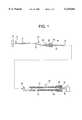
- FIG. 1is a partially-exploded elevational view, somewhat schematic, of a surgical tool with surgical field illuminator in accordance with one embodiment of the invention
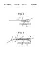
- FIG. 2is an elevational view, somewhat schematic and in partial cross-section, of a surgical field illuminator in accordance with a second embodiment
- FIG. 3is an elevational view, somewhat schematic and in partial cross-section, of a portion of a surgical tool with surgical field illuminator in accordance with another embodiment
- FIG. 4is a schematic view in partial cross-section showing a light-conveying member for use with the present invention.
- FIG. 5is a perspective view, somewhat schematic and in partial cross-section, of a fiber optic bundle for use in accordance with one embodiment of the invention.
- a surgical tool with surgical field illuminatorin accordance with one embodiment of the present invention includes a light-conveying fiber optic member 10 having a body portion 12, a light-receiving end 14 and a light-delivering end 16.
- a connector 17Adjacent the light-receiving end 14 of fiber optic member 10 is a connector 17 which may be formed of any suitable material, such as stainless steel tubing.
- the light-receiving end 14 of fiber optic member 10is optically connectable to a source of light 18.
- the present inventionmay include a surgical tool such as a micro-retractor cannula 20.
- Cannula 20includes a malleable stainless steel tube 22.
- the surgical tool 20is a micro-retractor cannula as shown in FIG. 1, the cannula advantageously has a length within the range of from about 4-8 inches, more preferably about 6 inches.
- Tube 22preferably has an outer diameter of about 1.5-3 mm, more preferably about 2 mm, and an inner diameter of about 1-2 mm, more preferably about 1.2 mm.
- stainless steel tube 22 of cannula 20can surround a part 24 of the body portion 12 of fiber optic member 10 adjacent the light-delivering end 16 of fiber optic member 10.
- the stainless steel tube 22may be surrounded by a polymeric sheath 23 of heat shrinking material.
- a connectoris provided for connecting the fiber optic member 10 with a surgical tool 20 such as shown in FIG. 1.
- the connectoris comprised of a Luer lock member 26 which mates with corresponding Luer lock member 28.
- connector member 26is connected to an intermediate section 30 of the body portion 12 of fiber optic member 10 spaced away from the light-delivering end 16.
- a tool-insertable section 24 of fiber optic member 12extends between connector member 26 and the light-delivering end 16 of fiber optic member 12.
- Luer lock connector member 28 thereofis mated with Luer lock connector member 26.
- connector members 26 and 28provide a releasable connection between the fiber optic member 12 and surgical tool 20, so as to releasably attach tool 20 to fiber optic member 12.
- fiber optic member 12is positioned in a corresponding opening 38 through connector member 26.
- Luer lock member 26is fixedly connected to an intermediate section 30 of the body portion 12 of fiber optic member 10 by any suitable means, such as epoxy adhesive.
- Luer lock member 28can be fixedly connected to the malleable stainless steel tube 22 of cannula 20 by any suitable means, such as press-fitting, epoxy adhesive and the like.
- a surgical tool 20is fixedly connected to an intermediate section 30 of the body portion 12 of the fiber optic member by any suitable means, such as by epoxy adhesive 44 as shown in FIG. 3.
- a light-transmitting member 32is provided adjacent a light-delivering port 34 in surgical tool 20.
- Member 32is at the end of stainless steel tubing 22 opposite Luer lock member 28. When assembled, the light-transmitting member 32 is positioned adjacent the light-delivering end 16 of the fiber optic member 10.
- the light-transmitting member 32is attached to port 34 of stainless steel tubing 22 of tool 20 by any suitable means, such as epoxy adhesive, press-fitting, etc.
- the light-transmitting member 32can be attached directly to the fiber optic member 10 as shown in FIG. 2, and include an external heat-shrink polymeric tubing 42.
- the fiber optic member 10 and the light-transmitting member 32can both be insertable into a corresponding surgical tool 20.
- fiber optic member 10 attached to light-transmitting member 32are externally attachable (by any suitable attachment member 19 such as a clip, tape or the like) to a nonilluminated surgical tool 20' such as a suction or suction-irrigation cannula, retractor, electrocautery device, and the like.
- the light-transmitting memberis a window of light-transmitting material having a thickness sufficient to reduce the light density transmitted through window 32 and out port 34 of surgical tool 20 so that a surface temperature of adjacent surgical region 36 rises less than about 55° C. when light is transmitted through window 32 to region 36.
- window 32is about 2-6 mm in thickness, and more preferably about 4 mm in thickness.
- the light-transmitting membercan be formed of a plastic, glass or the like. Suitable plastics include acrylic plastics such as PMMA (polymethylmethacrylate), polycarbonate plastics, and the like. Suitable glass materials include borosilicate glass such as BK 7, silica (quartz) glass, and the like.
- FIG. 3shows an embodiment where the light-transmitting member 32 is a window of light-transmitting material, the window being spaced away from the light-delivering end 16 of the fiber optic member 10 by a distance greater than about 0.001 inch and less than about 0.1 inch, so that light transmitted out port 34 and through window 32 raises the surface temperature of an adjacent surgical region less than about 55° C. when light is transmitted through window 32 to the region.
- the light-transmitting member 32is a window of light-transmitting material, the window being spaced away from the light-delivering end 16 of the fiber optic member 10 by a distance greater than about 0.001 inch and less than about 0.1 inch, so that light transmitted out port 34 and through window 32 raises the surface temperature of an adjacent surgical region less than about 55° C. when light is transmitted through window 32 to the region.
- a proximal strain-relieving member 40 formed of flexible rubber-like materialis provided proximal to Luer lock connector member 26.
- the malleable stainless steel tubing 22is covered on its outer surface with medical grade heat-shrink polymeric tubing 42.
- a second light-conveying member 46is provided, positioned between the light-receiving end 14 and the source of light 18, for optically connecting the light-receiving end 14 with source of light 18.
- the light-delivering end 47 of the second light-conveying member 46is spaced apart from the light-receiving end 14 of fiber optic member 10.
- the light-delivering end 47 of the second fiber optic member 46is spaced apart from the light-receiving end 14 a distance greater than about 0.01 inch and less than about 0.1 inch.
- the spacing between the quartz fiber and a 1.0 mm diameter acrylic fiber opticshould approximate 0.07 inch, corresponding to about 18% coupling efficiency, so as to minimize potential damage to the acrylic fiber.
- This embodimentcan utilize a fiber optic connector 49 such as is disclosed in commonly-owned U.S. Pat. No. 5,446,818, incorporated herein by reference, with or without a fiber optic coupler 51 as disclosed in commonly-owned U.S. Pat. No. 5,452,392, also incorporated herein by reference.
- the fiber optic member 10is a single fiber optic filament having a diameter of from about 0.1-2 mm, preferably about 1 mm and most preferably is formed of a flexible plastic material, preferably acrylic.
- the light-conveying fiber optic member 10is a bundle 10' of optical fibers, as shown in FIG. 5.
- the inventionalso may utilize surgical tools other than a micro-retractor cannula, including surgical suction or suction-irrigation cannulae, electrocautery devices, non-malleable retractors, and power tools.
- a surgical tool in accordance with the present inventionmay itself be attached to other non-illuminated surgical tools 20' by a suitable attachment member 19 (see FIG. 3).
- Suitable surgical tools 20'are exemplified above, and in accordance with this embodiment, provide illuminated surgical devices as exemplified in FIG. 3.
- the present inventioncan provide a lighted device which also may be malleable, such that the illumination can be directed to a desired position by the surgeon during a surgical procedure.
- the malleable endcan also be used as a retractor.
- malleable lighted retractorscan be used for trans-illumination of tissue during retraction.
- the present inventionprovides several advantages over other types of lighted retractors, as such typically are fixed in configuration and cannot be modified in shape during a surgical procedure.
- the inventionalso provides embodiments in which the tool 20 can be disposable and easily replaced utilizing a Luer lock connecting member.
Landscapes
- Physics & Mathematics (AREA)
- General Physics & Mathematics (AREA)
- Optics & Photonics (AREA)
- Surgical Instruments (AREA)
Abstract
Description
Claims (40)
Priority Applications (5)
| Application Number | Priority Date | Filing Date | Title |
|---|---|---|---|
| US08/657,098US6129662A (en) | 1996-06-03 | 1996-06-03 | Surgical tool with surgical field illuminator |
| EP97927636AEP0902905A1 (en) | 1996-06-03 | 1997-05-15 | Surgical tool with surgical field illuminator |
| AU32056/97AAU3205697A (en) | 1996-06-03 | 1997-05-15 | Surgical tool with surgical field illuminator |
| PCT/US1997/008191WO1997046902A1 (en) | 1996-06-03 | 1997-05-15 | Surgical tool with surgical field illuminator |
| TW086107491ATW338716B (en) | 1996-06-03 | 1997-09-23 | Surgical tool with surgical field illuminator |
Applications Claiming Priority (1)
| Application Number | Priority Date | Filing Date | Title |
|---|---|---|---|
| US08/657,098US6129662A (en) | 1996-06-03 | 1996-06-03 | Surgical tool with surgical field illuminator |
Publications (1)
| Publication Number | Publication Date |
|---|---|
| US6129662Atrue US6129662A (en) | 2000-10-10 |
Family
ID=24635812
Family Applications (1)
| Application Number | Title | Priority Date | Filing Date |
|---|---|---|---|
| US08/657,098Expired - Fee RelatedUS6129662A (en) | 1996-06-03 | 1996-06-03 | Surgical tool with surgical field illuminator |
Country Status (5)
| Country | Link |
|---|---|
| US (1) | US6129662A (en) |
| EP (1) | EP0902905A1 (en) |
| AU (1) | AU3205697A (en) |
| TW (1) | TW338716B (en) |
| WO (1) | WO1997046902A1 (en) |
Cited By (50)
| Publication number | Priority date | Publication date | Assignee | Title |
|---|---|---|---|---|
| WO2003019073A1 (en)* | 2001-08-23 | 2003-03-06 | Lumitex, Inc. | Light delivery systems and applications thereof |
| US20030169603A1 (en)* | 2002-03-05 | 2003-09-11 | Luloh K. Peter | Apparatus and method for illuminating a field of view within an eye |
| US6648902B2 (en) | 2000-07-20 | 2003-11-18 | Gmp Surgical Solutions, Inc. | Fiberoptic lighting accessory |
| US20040032751A1 (en)* | 2001-07-20 | 2004-02-19 | Solovay Kenneth S. | Light coupling assembly |
| US20040143169A1 (en)* | 2002-08-02 | 2004-07-22 | Branch Charles L. | Systems and techniques for illuminating a surgical space |
| US20040143167A1 (en)* | 2002-08-02 | 2004-07-22 | Branch Charles L. | Systems and techniques for illuminating a surgical space |
| US20040225191A1 (en)* | 2003-03-04 | 2004-11-11 | Olympus Corporation | Endoscopic treatment system and anastomotic method using this system |
| US20050203561A1 (en)* | 2004-03-09 | 2005-09-15 | Palmer Joetta R. | Lighted dissector and method for use |
| US20050203562A1 (en)* | 2004-03-09 | 2005-09-15 | Palmer Joetta R. | Lighted dissector and method for use |
| US20060190006A1 (en)* | 2005-02-21 | 2006-08-24 | Japan Atomic Energy Agency | Small bowel endoscope of ileus tube type that enables laser inspection and therapy |
| US20060291195A1 (en)* | 2005-06-13 | 2006-12-28 | Horrell Robin S | Compact lighting system attachable to a surgical tool and method of use thereof |
| US20070189004A1 (en)* | 2005-12-28 | 2007-08-16 | Guy Dickes | Illum-A-Field Modification of Medical and Surgical Instruments |
| US20080021278A1 (en)* | 2006-07-24 | 2008-01-24 | Leonard Robert F | Surgical device with removable end effector |
| US20080287937A1 (en)* | 2007-05-15 | 2008-11-20 | Warsaw Orthopedic, Inc. | Surgical Instrument for Illuminating and Monitoring a Surgical Site |
| US7507235B2 (en) | 2001-01-13 | 2009-03-24 | Medtronic, Inc. | Method and system for organ positioning and stabilization |
| US20090163897A1 (en)* | 2007-12-19 | 2009-06-25 | Skinner Allen W | Illuminated Ophthalmic Instruments |
| US7566334B2 (en) | 2004-06-02 | 2009-07-28 | Medtronic, Inc. | Ablation device with jaws |
| US7628780B2 (en) | 2001-01-13 | 2009-12-08 | Medtronic, Inc. | Devices and methods for interstitial injection of biologic agents into tissue |
| US7740623B2 (en) | 2001-01-13 | 2010-06-22 | Medtronic, Inc. | Devices and methods for interstitial injection of biologic agents into tissue |
| US7744562B2 (en) | 2003-01-14 | 2010-06-29 | Medtronics, Inc. | Devices and methods for interstitial injection of biologic agents into tissue |
| US7967816B2 (en) | 2002-01-25 | 2011-06-28 | Medtronic, Inc. | Fluid-assisted electrosurgical instrument with shapeable electrode |
| US8047987B2 (en) | 2006-05-26 | 2011-11-01 | Invuity, Inc. | Blade insert illuminator |
| US8088066B2 (en) | 2007-10-24 | 2012-01-03 | Invuity, Inc. | Blade insert illuminator |
| US20120253137A1 (en)* | 2005-02-18 | 2012-10-04 | Invuity, Inc. | Surgical illumination system |
| US20130053648A1 (en)* | 2011-08-24 | 2013-02-28 | Mako Surgical Corporation | Surgical Tool for Selectively Illuminating a Surgical Volume |
| US8409088B2 (en) | 2006-01-18 | 2013-04-02 | Invuity, Inc. | Retractor illumination system |
| US8430813B2 (en) | 2006-05-26 | 2013-04-30 | Depuy Spine, Inc. | Illuminated surgical access system including a surgical access device and integrated light emitter |
| WO2016073037A1 (en)* | 2014-11-06 | 2016-05-12 | Novartis Ag | Removing infrared (ir) light from an ophthalmic illumination system |
| US20160166433A1 (en)* | 2014-12-12 | 2016-06-16 | Carl Zeiss Meditec Ag | Surgical instrument |
| US9851060B2 (en) | 2013-04-01 | 2017-12-26 | Vinod V. Pathy | Lighting device for attachment to a tool |
| US9872705B2 (en) | 2013-10-07 | 2018-01-23 | Regentis Biomaterials Ltd. | Treatment of cavities in a human body |
| US9895519B2 (en) | 2013-10-07 | 2018-02-20 | Regentis Biomaterials Ltd. | Treatment of cavities in a human body |
| US10045686B2 (en) | 2008-11-12 | 2018-08-14 | Trice Medical, Inc. | Tissue visualization and modification device |
| US10342579B2 (en) | 2014-01-13 | 2019-07-09 | Trice Medical, Inc. | Fully integrated, disposable tissue visualization device |
| US10405886B2 (en) | 2015-08-11 | 2019-09-10 | Trice Medical, Inc. | Fully integrated, disposable tissue visualization device |
| US10602960B2 (en) | 2013-07-24 | 2020-03-31 | Cook Medical Technologies Llc | Locating device |
| USD884236S1 (en) | 2018-10-04 | 2020-05-12 | Integra Lifesciences Corporation | Wearable headgear device |
| US10724716B2 (en) | 2018-10-04 | 2020-07-28 | Integra Lifesciences Corporation | Head wearable devices and methods |
| USD901737S1 (en) | 2018-10-04 | 2020-11-10 | Integra Lifesciences Corporation | Wearable headgear device |
| US10980571B2 (en) | 2017-08-15 | 2021-04-20 | Covidien Lp | Occlusion devices, systems, and methods |
| US11090082B2 (en) | 2017-05-12 | 2021-08-17 | Covidien Lp | Colpotomy systems, devices, and methods with rotational cutting |
| USD938095S1 (en) | 2013-04-01 | 2021-12-07 | Pathy Medical, Llc | Lighting device |
| US11213320B2 (en) | 2017-05-12 | 2022-01-04 | Covidien Lp | Uterine manipulator with detachable cup and locking occluder |
| US11253308B2 (en) | 2017-05-12 | 2022-02-22 | Covidien Lp | Colpotomy systems, devices, and methods with rotational cutting |
| US11344292B2 (en) | 2018-06-14 | 2022-05-31 | Covidien Lp | Trans-vaginal cuff anchor and method of deploying same |
| US11382711B2 (en) | 2008-08-13 | 2022-07-12 | Invuity, Inc. | Cyclo olefin polymer and copolymer medical devices |
| US11547446B2 (en) | 2014-01-13 | 2023-01-10 | Trice Medical, Inc. | Fully integrated, disposable tissue visualization device |
| US11622753B2 (en) | 2018-03-29 | 2023-04-11 | Trice Medical, Inc. | Fully integrated endoscope with biopsy capabilities and methods of use |
| US11969203B2 (en) | 2020-02-14 | 2024-04-30 | Covidien Lp | Colpotomy system with applied energy |
| US12035889B2 (en) | 2008-07-22 | 2024-07-16 | Trice Medical, Inc. | Tissue modification devices and methods of using the same |
Families Citing this family (1)
| Publication number | Priority date | Publication date | Assignee | Title |
|---|---|---|---|---|
| WO2008018804A1 (en)* | 2006-08-08 | 2008-02-14 | Mony Paz | Combination dental hand tool |
Citations (39)
| Publication number | Priority date | Publication date | Assignee | Title |
|---|---|---|---|---|
| US3951514A (en)* | 1974-12-23 | 1976-04-20 | International Telephone And Telegraph Corporation | Connector member |
| EP0082691A1 (en)* | 1981-12-18 | 1983-06-29 | Olympus Optical Co., Ltd. | An illuminating device having optical light guide formed as fibre bundle |
| US4516190A (en)* | 1983-12-29 | 1985-05-07 | Luxtec Corporation | Surgical headlamp |
| US4666246A (en)* | 1983-09-20 | 1987-05-19 | Olympus Optical Co., Ltd. | Illuminating optical system for endoscopes |
| US4730885A (en)* | 1985-07-11 | 1988-03-15 | Asahi Kogaku Kogyo Kabushiki Kaisha | Laser fiber connector |
| US4757431A (en)* | 1986-07-01 | 1988-07-12 | Laser Media | Off-axis application of concave spherical reflectors as condensing and collecting optics |
| US4759348A (en)* | 1981-09-28 | 1988-07-26 | Cawood Charles David | Endoscope assembly and surgical instrument for use therewith |
| US4782819A (en)* | 1987-02-25 | 1988-11-08 | Adair Edwin Lloyd | Optical catheter |
| US4790295A (en)* | 1986-12-16 | 1988-12-13 | Olympus Optical Co., Ltd. | Endoscope having transparent resin sealing layer |
| US4870952A (en)* | 1983-10-28 | 1989-10-03 | Miquel Martinez | Fiber optic illuminator for use in surgery |
| EP0341919A2 (en)* | 1988-05-06 | 1989-11-15 | Mitsubishi Rayon Co., Ltd. | Light attenuator and process for fabrication thereof |
| US4905082A (en)* | 1987-05-06 | 1990-02-27 | Olympus Optical Co., Ltd. | Rigid video endoscope having a detachable imaging unit |
| US4986622A (en)* | 1989-06-08 | 1991-01-22 | Miguel Martinez | Fiber optic light transmission apparatus |
| US5034010A (en)* | 1985-03-22 | 1991-07-23 | Massachusetts Institute Of Technology | Optical shield for a laser catheter |
| US5051824A (en)* | 1989-10-30 | 1991-09-24 | Olympus Optical Co., Ltd. | Electronic scope having detachable frame to which solid state imaging device is fastened |
| US5131380A (en)* | 1991-06-13 | 1992-07-21 | Heller Richard M | Softwall medical tube with fiberoptic light conductor therein and method of use |
| US5190028A (en)* | 1991-02-04 | 1993-03-02 | Citation Medical Corporation | Method for manufacturing a disposable arthroscopic probe |
| US5197457A (en)* | 1990-09-12 | 1993-03-30 | Adair Edwin Lloyd | Deformable and removable sheath for optical catheter |
| US5337735A (en)* | 1992-12-28 | 1994-08-16 | Albert Salerno | Fiber-lighted stylet |
| US5337734A (en)* | 1992-10-29 | 1994-08-16 | Advanced Polymers, Incorporated | Disposable sheath with optically transparent window formed continuously integral therewith |
| US5351322A (en)* | 1992-08-18 | 1994-09-27 | Nirsystems Incorporated | Fiber optic probe |
| US5355285A (en)* | 1993-01-12 | 1994-10-11 | Hicks John W | Surgeon's headlight system |
| US5361316A (en)* | 1992-03-05 | 1994-11-01 | Lederle (Japan) Ltd. | Optical fiber laser device for transmitting a pulse laser beam |
| US5396880A (en)* | 1992-04-08 | 1995-03-14 | Danek Medical, Inc. | Endoscope for direct visualization of the spine and epidural space |
| US5414600A (en)* | 1993-07-30 | 1995-05-09 | Cogent Light Technologies, Inc. | Condensing and collecting optical system using an ellipsoidal reflector |
| US5423321A (en)* | 1993-02-11 | 1995-06-13 | Fontenot; Mark G. | Detection of anatomic passages using infrared emitting catheter |
| US5430620A (en)* | 1993-10-08 | 1995-07-04 | Cogent Light Technologies, Inc. | Compact surgical illumination system capable of dynamically adjusting the resulting field of illumination |
| US5446818A (en)* | 1994-05-05 | 1995-08-29 | Cogent Light Technologies, Inc. | Fiber optic connector having a shielding apparatus for protecting the exposed end of a fiber optic |
| US5450293A (en)* | 1993-12-30 | 1995-09-12 | Hoffman; Elliott S. | Finger mounted fiber optic illumination system |
| US5452392A (en)* | 1994-06-20 | 1995-09-19 | Cogent Light Technologies, Inc. | Fiber optic, coupling apparatus having means for preventing thermal damage to the fiber optic at the fiber-to-light source coupling |
| EP0743542A2 (en)* | 1995-05-19 | 1996-11-20 | Bridgestone Corporation | Optical waveguide tube |
| US5605532A (en)* | 1995-10-20 | 1997-02-25 | Vista Medical Technologies, Inc. | Fog-free endoscope |
| US5632740A (en)* | 1991-01-30 | 1997-05-27 | Ceram Optec Industries, Inc. | Illuminated leading probe device |
| US5672171A (en)* | 1994-06-30 | 1997-09-30 | American Medical Systems, Inc. | Apparatus and method for interstitial laser treatment |
| US5681264A (en)* | 1995-10-25 | 1997-10-28 | Ryan, Jr.; Edwin H. | Shielded illumination device for ophthalmic surgery and the like |
| US5685839A (en)* | 1982-08-12 | 1997-11-11 | Edwards; Stuart D. | Ultrasound probe with thermal sensing |
| US5699795A (en)* | 1995-03-31 | 1997-12-23 | Board Of Regents, The University Of Texas System | Optical probe for the detection of cervical neoplasia using fluorescence spectroscopy and apparatus incorporating same |
| US5733241A (en)* | 1996-02-01 | 1998-03-31 | King; George Hwa Kou | Fiberoptic intubation stylet |
| US5785645A (en)* | 1996-04-16 | 1998-07-28 | Synergetics, Inc. | Beveled tip illuminator for microsurgery |
- 1996
- 1996-06-03USUS08/657,098patent/US6129662A/ennot_activeExpired - Fee Related
- 1997
- 1997-05-15AUAU32056/97Apatent/AU3205697A/ennot_activeAbandoned
- 1997-05-15WOPCT/US1997/008191patent/WO1997046902A1/ennot_activeApplication Discontinuation
- 1997-05-15EPEP97927636Apatent/EP0902905A1/ennot_activeWithdrawn
- 1997-09-23TWTW086107491Apatent/TW338716B/enactive
Patent Citations (39)
| Publication number | Priority date | Publication date | Assignee | Title |
|---|---|---|---|---|
| US3951514A (en)* | 1974-12-23 | 1976-04-20 | International Telephone And Telegraph Corporation | Connector member |
| US4759348A (en)* | 1981-09-28 | 1988-07-26 | Cawood Charles David | Endoscope assembly and surgical instrument for use therewith |
| EP0082691A1 (en)* | 1981-12-18 | 1983-06-29 | Olympus Optical Co., Ltd. | An illuminating device having optical light guide formed as fibre bundle |
| US5685839A (en)* | 1982-08-12 | 1997-11-11 | Edwards; Stuart D. | Ultrasound probe with thermal sensing |
| US4666246A (en)* | 1983-09-20 | 1987-05-19 | Olympus Optical Co., Ltd. | Illuminating optical system for endoscopes |
| US4870952A (en)* | 1983-10-28 | 1989-10-03 | Miquel Martinez | Fiber optic illuminator for use in surgery |
| US4516190A (en)* | 1983-12-29 | 1985-05-07 | Luxtec Corporation | Surgical headlamp |
| US5034010A (en)* | 1985-03-22 | 1991-07-23 | Massachusetts Institute Of Technology | Optical shield for a laser catheter |
| US4730885A (en)* | 1985-07-11 | 1988-03-15 | Asahi Kogaku Kogyo Kabushiki Kaisha | Laser fiber connector |
| US4757431A (en)* | 1986-07-01 | 1988-07-12 | Laser Media | Off-axis application of concave spherical reflectors as condensing and collecting optics |
| US4790295A (en)* | 1986-12-16 | 1988-12-13 | Olympus Optical Co., Ltd. | Endoscope having transparent resin sealing layer |
| US4782819A (en)* | 1987-02-25 | 1988-11-08 | Adair Edwin Lloyd | Optical catheter |
| US4905082A (en)* | 1987-05-06 | 1990-02-27 | Olympus Optical Co., Ltd. | Rigid video endoscope having a detachable imaging unit |
| EP0341919A2 (en)* | 1988-05-06 | 1989-11-15 | Mitsubishi Rayon Co., Ltd. | Light attenuator and process for fabrication thereof |
| US4986622A (en)* | 1989-06-08 | 1991-01-22 | Miguel Martinez | Fiber optic light transmission apparatus |
| US5051824A (en)* | 1989-10-30 | 1991-09-24 | Olympus Optical Co., Ltd. | Electronic scope having detachable frame to which solid state imaging device is fastened |
| US5197457A (en)* | 1990-09-12 | 1993-03-30 | Adair Edwin Lloyd | Deformable and removable sheath for optical catheter |
| US5632740A (en)* | 1991-01-30 | 1997-05-27 | Ceram Optec Industries, Inc. | Illuminated leading probe device |
| US5190028A (en)* | 1991-02-04 | 1993-03-02 | Citation Medical Corporation | Method for manufacturing a disposable arthroscopic probe |
| US5131380A (en)* | 1991-06-13 | 1992-07-21 | Heller Richard M | Softwall medical tube with fiberoptic light conductor therein and method of use |
| US5361316A (en)* | 1992-03-05 | 1994-11-01 | Lederle (Japan) Ltd. | Optical fiber laser device for transmitting a pulse laser beam |
| US5396880A (en)* | 1992-04-08 | 1995-03-14 | Danek Medical, Inc. | Endoscope for direct visualization of the spine and epidural space |
| US5351322A (en)* | 1992-08-18 | 1994-09-27 | Nirsystems Incorporated | Fiber optic probe |
| US5337734A (en)* | 1992-10-29 | 1994-08-16 | Advanced Polymers, Incorporated | Disposable sheath with optically transparent window formed continuously integral therewith |
| US5337735A (en)* | 1992-12-28 | 1994-08-16 | Albert Salerno | Fiber-lighted stylet |
| US5355285A (en)* | 1993-01-12 | 1994-10-11 | Hicks John W | Surgeon's headlight system |
| US5423321A (en)* | 1993-02-11 | 1995-06-13 | Fontenot; Mark G. | Detection of anatomic passages using infrared emitting catheter |
| US5414600A (en)* | 1993-07-30 | 1995-05-09 | Cogent Light Technologies, Inc. | Condensing and collecting optical system using an ellipsoidal reflector |
| US5430620A (en)* | 1993-10-08 | 1995-07-04 | Cogent Light Technologies, Inc. | Compact surgical illumination system capable of dynamically adjusting the resulting field of illumination |
| US5450293A (en)* | 1993-12-30 | 1995-09-12 | Hoffman; Elliott S. | Finger mounted fiber optic illumination system |
| US5446818A (en)* | 1994-05-05 | 1995-08-29 | Cogent Light Technologies, Inc. | Fiber optic connector having a shielding apparatus for protecting the exposed end of a fiber optic |
| US5452392A (en)* | 1994-06-20 | 1995-09-19 | Cogent Light Technologies, Inc. | Fiber optic, coupling apparatus having means for preventing thermal damage to the fiber optic at the fiber-to-light source coupling |
| US5672171A (en)* | 1994-06-30 | 1997-09-30 | American Medical Systems, Inc. | Apparatus and method for interstitial laser treatment |
| US5699795A (en)* | 1995-03-31 | 1997-12-23 | Board Of Regents, The University Of Texas System | Optical probe for the detection of cervical neoplasia using fluorescence spectroscopy and apparatus incorporating same |
| EP0743542A2 (en)* | 1995-05-19 | 1996-11-20 | Bridgestone Corporation | Optical waveguide tube |
| US5605532A (en)* | 1995-10-20 | 1997-02-25 | Vista Medical Technologies, Inc. | Fog-free endoscope |
| US5681264A (en)* | 1995-10-25 | 1997-10-28 | Ryan, Jr.; Edwin H. | Shielded illumination device for ophthalmic surgery and the like |
| US5733241A (en)* | 1996-02-01 | 1998-03-31 | King; George Hwa Kou | Fiberoptic intubation stylet |
| US5785645A (en)* | 1996-04-16 | 1998-07-28 | Synergetics, Inc. | Beveled tip illuminator for microsurgery |
Cited By (92)
| Publication number | Priority date | Publication date | Assignee | Title |
|---|---|---|---|---|
| US6739744B2 (en)* | 1997-07-02 | 2004-05-25 | Lumitex, Inc. | Light delivery systems and applications thereof |
| US6648902B2 (en) | 2000-07-20 | 2003-11-18 | Gmp Surgical Solutions, Inc. | Fiberoptic lighting accessory |
| US7628780B2 (en) | 2001-01-13 | 2009-12-08 | Medtronic, Inc. | Devices and methods for interstitial injection of biologic agents into tissue |
| US7507235B2 (en) | 2001-01-13 | 2009-03-24 | Medtronic, Inc. | Method and system for organ positioning and stabilization |
| US7740623B2 (en) | 2001-01-13 | 2010-06-22 | Medtronic, Inc. | Devices and methods for interstitial injection of biologic agents into tissue |
| US20040032751A1 (en)* | 2001-07-20 | 2004-02-19 | Solovay Kenneth S. | Light coupling assembly |
| US7290915B2 (en) | 2001-07-20 | 2007-11-06 | Solovay Kenneth S | Light coupling assembly |
| WO2003019073A1 (en)* | 2001-08-23 | 2003-03-06 | Lumitex, Inc. | Light delivery systems and applications thereof |
| US7967816B2 (en) | 2002-01-25 | 2011-06-28 | Medtronic, Inc. | Fluid-assisted electrosurgical instrument with shapeable electrode |
| US20030169603A1 (en)* | 2002-03-05 | 2003-09-11 | Luloh K. Peter | Apparatus and method for illuminating a field of view within an eye |
| US20040143169A1 (en)* | 2002-08-02 | 2004-07-22 | Branch Charles L. | Systems and techniques for illuminating a surgical space |
| US7223233B2 (en) | 2002-08-02 | 2007-05-29 | Warsaw Orthopedic, Inc. | Systems and techniques for illuminating a surgical space |
| US7959651B2 (en) | 2002-08-02 | 2011-06-14 | Warsaw Orthopedic, Inc. | Systems and techniques for illuminating a surgical space |
| US20070225571A1 (en)* | 2002-08-02 | 2007-09-27 | Branch Charles L | Systems and techniques for illuminating a surgical space |
| US20040143167A1 (en)* | 2002-08-02 | 2004-07-22 | Branch Charles L. | Systems and techniques for illuminating a surgical space |
| US7556601B2 (en) | 2002-08-02 | 2009-07-07 | Warsaw Orthopedic, Inc. | Systems and techniques for illuminating a surgical space |
| US8273072B2 (en) | 2003-01-14 | 2012-09-25 | Medtronic, Inc. | Devices and methods for interstitial injection of biologic agents into tissue |
| US7744562B2 (en) | 2003-01-14 | 2010-06-29 | Medtronics, Inc. | Devices and methods for interstitial injection of biologic agents into tissue |
| US7273451B2 (en)* | 2003-03-04 | 2007-09-25 | Olympus Corporation | Endoscopic treatment system and anastomotic method using this system |
| US20040225191A1 (en)* | 2003-03-04 | 2004-11-11 | Olympus Corporation | Endoscopic treatment system and anastomotic method using this system |
| US20050203562A1 (en)* | 2004-03-09 | 2005-09-15 | Palmer Joetta R. | Lighted dissector and method for use |
| US20050203561A1 (en)* | 2004-03-09 | 2005-09-15 | Palmer Joetta R. | Lighted dissector and method for use |
| US8162941B2 (en) | 2004-06-02 | 2012-04-24 | Medtronic, Inc. | Ablation device with jaws |
| US7566334B2 (en) | 2004-06-02 | 2009-07-28 | Medtronic, Inc. | Ablation device with jaws |
| US7875028B2 (en) | 2004-06-02 | 2011-01-25 | Medtronic, Inc. | Ablation device with jaws |
| US20120253137A1 (en)* | 2005-02-18 | 2012-10-04 | Invuity, Inc. | Surgical illumination system |
| US20060190006A1 (en)* | 2005-02-21 | 2006-08-24 | Japan Atomic Energy Agency | Small bowel endoscope of ileus tube type that enables laser inspection and therapy |
| US8945195B2 (en)* | 2005-02-21 | 2015-02-03 | Japan Atomic Energy Agency | Small bowel endoscope of ileus tube type that enables laser inspection and therapy |
| US20060291195A1 (en)* | 2005-06-13 | 2006-12-28 | Horrell Robin S | Compact lighting system attachable to a surgical tool and method of use thereof |
| US7270439B2 (en)* | 2005-06-13 | 2007-09-18 | Horrell Robin S | Compact lighting system attachable to a surgical tool and method of use thereof |
| US20070189004A1 (en)* | 2005-12-28 | 2007-08-16 | Guy Dickes | Illum-A-Field Modification of Medical and Surgical Instruments |
| US9271709B2 (en) | 2006-01-18 | 2016-03-01 | Invuity, Inc. | Retractor illumination system |
| US9844364B2 (en) | 2006-01-18 | 2017-12-19 | Invuity, Inc. | Retractor illumination system |
| US9271710B2 (en) | 2006-01-18 | 2016-03-01 | Invuity, Inc. | Retractor illumination system |
| US9055935B2 (en) | 2006-01-18 | 2015-06-16 | Invuity, Inc. | Retractor illumination system |
| US8409088B2 (en) | 2006-01-18 | 2013-04-02 | Invuity, Inc. | Retractor illumination system |
| US8430813B2 (en) | 2006-05-26 | 2013-04-30 | Depuy Spine, Inc. | Illuminated surgical access system including a surgical access device and integrated light emitter |
| US8920316B2 (en) | 2006-05-26 | 2014-12-30 | Invuity, Inc. | Blade insert illuminator |
| US8047987B2 (en) | 2006-05-26 | 2011-11-01 | Invuity, Inc. | Blade insert illuminator |
| US9877639B2 (en) | 2006-05-26 | 2018-01-30 | Invuity, Inc. | Blade insert illuminator |
| US9241617B2 (en) | 2006-05-26 | 2016-01-26 | Invuity, Inc. | Blade insert illuminator |
| US20080021278A1 (en)* | 2006-07-24 | 2008-01-24 | Leonard Robert F | Surgical device with removable end effector |
| US20080287937A1 (en)* | 2007-05-15 | 2008-11-20 | Warsaw Orthopedic, Inc. | Surgical Instrument for Illuminating and Monitoring a Surgical Site |
| US10582844B2 (en) | 2007-10-24 | 2020-03-10 | Invuity, Inc. | Blade insert illuminator |
| US12161301B2 (en) | 2007-10-24 | 2024-12-10 | Invuity, Inc. | Blade insert illuminator |
| US9468366B2 (en) | 2007-10-24 | 2016-10-18 | Invuity, Inc. | Blade insert illuminator |
| US8088066B2 (en) | 2007-10-24 | 2012-01-03 | Invuity, Inc. | Blade insert illuminator |
| US11583175B2 (en) | 2007-10-24 | 2023-02-21 | Invuity, Inc. | Blade insert illuminator |
| US9060707B2 (en) | 2007-10-24 | 2015-06-23 | Invuity, Inc. | Blade insert illuminator |
| US9986901B2 (en) | 2007-10-24 | 2018-06-05 | Invuity, Inc. | Blade insert illuminator |
| US20090163897A1 (en)* | 2007-12-19 | 2009-06-25 | Skinner Allen W | Illuminated Ophthalmic Instruments |
| US12035889B2 (en) | 2008-07-22 | 2024-07-16 | Trice Medical, Inc. | Tissue modification devices and methods of using the same |
| US11382711B2 (en) | 2008-08-13 | 2022-07-12 | Invuity, Inc. | Cyclo olefin polymer and copolymer medical devices |
| US10045686B2 (en) | 2008-11-12 | 2018-08-14 | Trice Medical, Inc. | Tissue visualization and modification device |
| US10722318B2 (en)* | 2011-08-24 | 2020-07-28 | Mako Surgical Corp. | Surgical tools for selectively illuminating a surgical volume |
| US20130053648A1 (en)* | 2011-08-24 | 2013-02-28 | Mako Surgical Corporation | Surgical Tool for Selectively Illuminating a Surgical Volume |
| US9851060B2 (en) | 2013-04-01 | 2017-12-26 | Vinod V. Pathy | Lighting device for attachment to a tool |
| USD991542S1 (en) | 2013-04-01 | 2023-07-04 | Pathy Medical, Llc | Lighting device |
| US10816147B2 (en) | 2013-04-01 | 2020-10-27 | Pathy Medical, Llc | Lighting device with cavity for removably attaching to a tool |
| US11519569B2 (en) | 2013-04-01 | 2022-12-06 | Pathy Medical, Llc | Lighting device with cavity for removably attaching to a tool |
| USD938095S1 (en) | 2013-04-01 | 2021-12-07 | Pathy Medical, Llc | Lighting device |
| US10602960B2 (en) | 2013-07-24 | 2020-03-31 | Cook Medical Technologies Llc | Locating device |
| US9895519B2 (en) | 2013-10-07 | 2018-02-20 | Regentis Biomaterials Ltd. | Treatment of cavities in a human body |
| US9872705B2 (en) | 2013-10-07 | 2018-01-23 | Regentis Biomaterials Ltd. | Treatment of cavities in a human body |
| US10342579B2 (en) | 2014-01-13 | 2019-07-09 | Trice Medical, Inc. | Fully integrated, disposable tissue visualization device |
| US11547446B2 (en) | 2014-01-13 | 2023-01-10 | Trice Medical, Inc. | Fully integrated, disposable tissue visualization device |
| WO2016073037A1 (en)* | 2014-11-06 | 2016-05-12 | Novartis Ag | Removing infrared (ir) light from an ophthalmic illumination system |
| US20160166433A1 (en)* | 2014-12-12 | 2016-06-16 | Carl Zeiss Meditec Ag | Surgical instrument |
| US10945588B2 (en) | 2015-08-11 | 2021-03-16 | Trice Medical, Inc. | Fully integrated, disposable tissue visualization device |
| US10405886B2 (en) | 2015-08-11 | 2019-09-10 | Trice Medical, Inc. | Fully integrated, disposable tissue visualization device |
| US11090082B2 (en) | 2017-05-12 | 2021-08-17 | Covidien Lp | Colpotomy systems, devices, and methods with rotational cutting |
| US12324607B2 (en) | 2017-05-12 | 2025-06-10 | Covidien Lp | Uterine manipulator with detachable cup and locking occluder |
| US11213320B2 (en) | 2017-05-12 | 2022-01-04 | Covidien Lp | Uterine manipulator with detachable cup and locking occluder |
| US11253308B2 (en) | 2017-05-12 | 2022-02-22 | Covidien Lp | Colpotomy systems, devices, and methods with rotational cutting |
| US10980571B2 (en) | 2017-08-15 | 2021-04-20 | Covidien Lp | Occlusion devices, systems, and methods |
| US11622753B2 (en) | 2018-03-29 | 2023-04-11 | Trice Medical, Inc. | Fully integrated endoscope with biopsy capabilities and methods of use |
| US12193660B2 (en) | 2018-06-14 | 2025-01-14 | Covidien Lp | Trans-vaginal cuff anchor and method of deploying same |
| US11344292B2 (en) | 2018-06-14 | 2022-05-31 | Covidien Lp | Trans-vaginal cuff anchor and method of deploying same |
| US11555605B2 (en) | 2018-10-04 | 2023-01-17 | Integra Lifesciences Corporation | Head wearable devices and methods |
| USD884236S1 (en) | 2018-10-04 | 2020-05-12 | Integra Lifesciences Corporation | Wearable headgear device |
| US10724716B2 (en) | 2018-10-04 | 2020-07-28 | Integra Lifesciences Corporation | Head wearable devices and methods |
| USD901737S1 (en) | 2018-10-04 | 2020-11-10 | Integra Lifesciences Corporation | Wearable headgear device |
| US11635198B2 (en) | 2018-10-04 | 2023-04-25 | Integra Lifesciences Corporation | Head wearable devices and methods |
| USD987145S1 (en) | 2018-10-04 | 2023-05-23 | Integra Lifesciences Corporation | Wearable headgear device |
| US11674681B2 (en) | 2018-10-04 | 2023-06-13 | Integra Lifesciences Corporation | Head wearable devices and methods |
| US11067267B2 (en) | 2018-10-04 | 2021-07-20 | Integra Lifesciences Corporation | Head wearable devices and methods |
| US11835211B2 (en) | 2018-10-04 | 2023-12-05 | Integra Lifesciences Corporation | Head wearable devices and methods |
| USD935074S1 (en) | 2018-10-04 | 2021-11-02 | Integra Lifesciences Corporation | Wearable headgear device |
| US10830428B2 (en) | 2018-10-04 | 2020-11-10 | Integra Lifesciences Corporation | Head wearable devices and methods |
| US11268686B2 (en) | 2018-10-04 | 2022-03-08 | Integra Lifesciences Corporation | Head wearable devices and methods |
| US11255533B2 (en) | 2018-10-04 | 2022-02-22 | Integra Lifesciences Corporation | Head wearable devices and methods |
| US11969203B2 (en) | 2020-02-14 | 2024-04-30 | Covidien Lp | Colpotomy system with applied energy |
Also Published As
| Publication number | Publication date |
|---|---|
| WO1997046902A1 (en) | 1997-12-11 |
| AU3205697A (en) | 1998-01-05 |
| TW338716B (en) | 1998-08-21 |
| EP0902905A1 (en) | 1999-03-24 |
Similar Documents
| Publication | Publication Date | Title |
|---|---|---|
| US6129662A (en) | Surgical tool with surgical field illuminator | |
| WO1997046902A9 (en) | Surgical tool with surgical field illuminator | |
| US4870952A (en) | Fiber optic illuminator for use in surgery | |
| US4562832A (en) | Medical instrument and light pipe illumination assembly | |
| WO2003034905A3 (en) | Miniature endoscope with imaging fiber system | |
| US7470269B2 (en) | Ophthalmic surgery light transmitting apparatus | |
| US5396366A (en) | Endoscope apparatus | |
| US5931670A (en) | Illuminated dental suction appliance | |
| EP2481339A3 (en) | Disposable fiber optic sheath. | |
| DK0565694T3 (en) | Laser unit | |
| CA2004139A1 (en) | Viewing laryngoscope | |
| EP1350458A3 (en) | Proximal coupler for optical fibers | |
| WO1993011699A1 (en) | Arthroscope having five functions | |
| CA2012535A1 (en) | Remote fiber optic medical procedure and device | |
| BR9807808A (en) | Micro-mechanical system. | |
| CA2143639A1 (en) | Sterilizable endoscope with separable disposable tube assembly | |
| DE69334029D1 (en) | ENDOSCOPE WITH STERILE CASE | |
| US6561973B1 (en) | Micro-endoscopic system | |
| ES8401315A1 (en) | Endoscope assembly and surgical instrument for use therewith. | |
| WO2007053591A3 (en) | Surgical wide-angle illuminator | |
| US6221028B1 (en) | Vitrectomy lens with integrated illuminator | |
| IT1233267B (en) | DENTAL FIBER OPTIC ENDOSCOPE | |
| CA2032458A1 (en) | Infrared delivery system with aiming component | |
| JP3607843B2 (en) | Endoscope | |
| JP3187136B2 (en) | Endoscope lighting system |
Legal Events
| Date | Code | Title | Description |
|---|---|---|---|
| AS | Assignment | Owner name:COGENT LIGHT TECHNOLOGIES, INC., CALIFORNIA Free format text:ASSIGNMENT OF ASSIGNORS INTEREST;ASSIGNORS:LI, KENNETH K.;SMITH, WAYNE;DAVIES, RICHARD B.;AND OTHERS;REEL/FRAME:008019/0680 Effective date:19960531 | |
| AS | Assignment | Owner name:WAVIEN, INC., CALIFORNIA Free format text:CHANGE OF NAME;ASSIGNOR:COGENT LIGHT TECHNOLOGIES, INC.;REEL/FRAME:013653/0913 Effective date:20010917 | |
| AS | Assignment | Owner name:CLT ASSOCIATES, L.P., NEW JERSEY Free format text:SECURITY AGREEMENT;ASSIGNOR:WAVIEN, INC.;REEL/FRAME:013678/0001 Effective date:20021211 | |
| REMI | Maintenance fee reminder mailed | ||
| LAPS | Lapse for failure to pay maintenance fees | ||
| STCH | Information on status: patent discontinuation | Free format text:PATENT EXPIRED DUE TO NONPAYMENT OF MAINTENANCE FEES UNDER 37 CFR 1.362 | |
| FP | Lapsed due to failure to pay maintenance fee | Effective date:20041010 | |
| AS | Assignment | Owner name:CLT ASSOCIATES, L.P., NEW JERSEY Free format text:INTELLECTUAL PROPERTY SECURITY AGREEMENT;ASSIGNOR:WAVIEN, INC.;REEL/FRAME:037159/0048 Effective date:20151123 | |
| AS | Assignment | Owner name:WAVIEN, INC., CALIFORNIA Free format text:RELEASE BY SECURED PARTY;ASSIGNOR:CLT ASSOCIATES, L.P.;REEL/FRAME:037397/0175 Effective date:20151217 |