US6129527A - Electrically operated linear motor with integrated flexure spring and circuit for use in reciprocating compressor - Google Patents
Electrically operated linear motor with integrated flexure spring and circuit for use in reciprocating compressorDownload PDFInfo
- Publication number
- US6129527A US6129527AUS09/292,984US29298499AUS6129527AUS 6129527 AUS6129527 AUS 6129527AUS 29298499 AUS29298499 AUS 29298499AUS 6129527 AUS6129527 AUS 6129527A
- Authority
- US
- United States
- Prior art keywords
- housing
- spring
- moveable
- reciprocating compressor
- fixed
- Prior art date
- Legal status (The legal status is an assumption and is not a legal conclusion. Google has not performed a legal analysis and makes no representation as to the accuracy of the status listed.)
- Expired - Lifetime
Links
- 239000012530fluidSubstances0.000claimsabstractdescription26
- 230000005291magnetic effectEffects0.000claimsdescription18
- 238000000429assemblyMethods0.000claimsdescription17
- 230000000712assemblyEffects0.000claimsdescription17
- 238000006073displacement reactionMethods0.000claimsdescription12
- 238000000034methodMethods0.000claimsdescription11
- 238000004804windingMethods0.000claimsdescription10
- 230000008878couplingEffects0.000claimsdescription6
- 238000010168coupling processMethods0.000claimsdescription6
- 238000005859coupling reactionMethods0.000claimsdescription6
- 230000003993interactionEffects0.000claimsdescription6
- 238000004891communicationMethods0.000claimsdescription4
- 230000006835compressionEffects0.000abstractdescription16
- 238000007906compressionMethods0.000abstractdescription16
- 238000010276constructionMethods0.000description8
- XEEYBQQBJWHFJM-UHFFFAOYSA-NIronChemical compound[Fe]XEEYBQQBJWHFJM-UHFFFAOYSA-N0.000description6
- 239000004020conductorSubstances0.000description6
- 230000004907fluxEffects0.000description5
- 229910052751metalInorganic materials0.000description5
- 239000002184metalSubstances0.000description5
- 229910052782aluminiumInorganic materials0.000description4
- XAGFODPZIPBFFR-UHFFFAOYSA-NaluminiumChemical compound[Al]XAGFODPZIPBFFR-UHFFFAOYSA-N0.000description4
- 238000007789sealingMethods0.000description4
- 125000006850spacer groupChemical group0.000description4
- 229910000639Spring steelInorganic materials0.000description3
- 230000008901benefitEffects0.000description3
- 229910052742ironInorganic materials0.000description3
- 235000000396ironNutrition0.000description3
- 239000000203mixtureSubstances0.000description3
- 230000010287polarizationEffects0.000description3
- 230000004323axial lengthEffects0.000description2
- 238000005452bendingMethods0.000description2
- DMFGNRRURHSENX-UHFFFAOYSA-Nberyllium copperChemical compound[Be].[Cu]DMFGNRRURHSENX-UHFFFAOYSA-N0.000description2
- 230000006872improvementEffects0.000description2
- 238000004519manufacturing processMethods0.000description2
- 230000007246mechanismEffects0.000description2
- 238000003801millingMethods0.000description2
- 230000007935neutral effectEffects0.000description2
- 229910000679solderInorganic materials0.000description2
- 229910001220stainless steelInorganic materials0.000description2
- 239000010935stainless steelSubstances0.000description2
- 239000000126substanceSubstances0.000description2
- 238000003486chemical etchingMethods0.000description1
- 239000002131composite materialSubstances0.000description1
- 239000012141concentrateSubstances0.000description1
- 238000001816coolingMethods0.000description1
- 125000004122cyclic groupChemical group0.000description1
- 238000000151depositionMethods0.000description1
- 238000013461designMethods0.000description1
- 230000001066destructive effectEffects0.000description1
- 230000000694effectsEffects0.000description1
- 230000005294ferromagnetic effectEffects0.000description1
- 239000003302ferromagnetic materialSubstances0.000description1
- 230000006870functionEffects0.000description1
- 239000011521glassSubstances0.000description1
- 238000010348incorporationMethods0.000description1
- WABPQHHGFIMREM-UHFFFAOYSA-Nlead(0)Chemical compound[Pb]WABPQHHGFIMREM-UHFFFAOYSA-N0.000description1
- 239000000463materialSubstances0.000description1
- 230000004048modificationEffects0.000description1
- 238000012986modificationMethods0.000description1
- 230000008569processEffects0.000description1
- 230000009467reductionEffects0.000description1
- 239000003507refrigerantSubstances0.000description1
- 238000005057refrigerationMethods0.000description1
- 230000003252repetitive effectEffects0.000description1
- 230000004044responseEffects0.000description1
- 230000000717retained effectEffects0.000description1
- 238000006467substitution reactionMethods0.000description1
Images


Classifications
- F—MECHANICAL ENGINEERING; LIGHTING; HEATING; WEAPONS; BLASTING
- F04—POSITIVE - DISPLACEMENT MACHINES FOR LIQUIDS; PUMPS FOR LIQUIDS OR ELASTIC FLUIDS
- F04B—POSITIVE-DISPLACEMENT MACHINES FOR LIQUIDS; PUMPS
- F04B39/00—Component parts, details, or accessories, of pumps or pumping systems specially adapted for elastic fluids, not otherwise provided for in, or of interest apart from, groups F04B25/00 - F04B37/00
- H—ELECTRICITY
- H02—GENERATION; CONVERSION OR DISTRIBUTION OF ELECTRIC POWER
- H02K—DYNAMO-ELECTRIC MACHINES
- H02K5/00—Casings; Enclosures; Supports
- H02K5/04—Casings or enclosures characterised by the shape, form or construction thereof
- H02K5/22—Auxiliary parts of casings not covered by groups H02K5/06-H02K5/20, e.g. shaped to form connection boxes or terminal boxes
- H02K5/225—Terminal boxes or connection arrangements
- F—MECHANICAL ENGINEERING; LIGHTING; HEATING; WEAPONS; BLASTING
- F04—POSITIVE - DISPLACEMENT MACHINES FOR LIQUIDS; PUMPS FOR LIQUIDS OR ELASTIC FLUIDS
- F04B—POSITIVE-DISPLACEMENT MACHINES FOR LIQUIDS; PUMPS
- F04B35/00—Piston pumps specially adapted for elastic fluids and characterised by the driving means to their working members, or by combination with, or adaptation to, specific driving engines or motors, not otherwise provided for
- F04B35/04—Piston pumps specially adapted for elastic fluids and characterised by the driving means to their working members, or by combination with, or adaptation to, specific driving engines or motors, not otherwise provided for the means being electric
- F04B35/045—Piston pumps specially adapted for elastic fluids and characterised by the driving means to their working members, or by combination with, or adaptation to, specific driving engines or motors, not otherwise provided for the means being electric using solenoids
- H—ELECTRICITY
- H02—GENERATION; CONVERSION OR DISTRIBUTION OF ELECTRIC POWER
- H02K—DYNAMO-ELECTRIC MACHINES
- H02K33/00—Motors with reciprocating, oscillating or vibrating magnet, armature or coil system
- H02K33/18—Motors with reciprocating, oscillating or vibrating magnet, armature or coil system with coil systems moving upon intermittent or reversed energisation thereof by interaction with a fixed field system, e.g. permanent magnets
- H—ELECTRICITY
- H02—GENERATION; CONVERSION OR DISTRIBUTION OF ELECTRIC POWER
- H02K—DYNAMO-ELECTRIC MACHINES
- H02K2211/00—Specific aspects not provided for in the other groups of this subclass relating to measuring or protective devices or electric components
- H02K2211/03—Machines characterised by circuit boards, e.g. pcb
Definitions
- the present inventiongenerally relates to motors having reciprocating shafts and, more particularly, to a reciprocating compressor having an electrically operated linear motor using an integrated flexure spring and circuit.
- cryocoolerssuch as long-life Stirling and pulse tube refrigerators are used in cooling applications including infrared sensor systems on aircraft and spacecraft.
- cryocoolerstypically include a linear-resonant or reciprocating compressor having a linear electric motor to compress and displace a refrigerant working fluid.
- the linear motorincludes a moveable, current-carrying coil, i.e., a moveable current coil, within a magnetic field to impart reciprocating, bi-directional linear forces in an axial direction to a moveable assembly of the linear motor.
- the moveable assemblyreciprocates in response to the linear forces applied thereto, the working fluid is compressed and displaced toward system components associated with the refrigeration process.
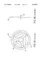
- FIG. 1is an illustration of a reciprocating compressor 10 which is disclosed in the publication "Design Equations And Scaling Laws For Linear Compressors With Flexure Springs", by E. Marquardt, R. Radebaugh and P. Kittel, Proceedings of the 7 th International Cryocooler Conference, pp. 783, 17-19, November 1992.
- a left half (which is a mirror image of the right half) of reciprocating compressor 10is depicted comprising a piston 14 driven by a linear motor, generally indicated at 16, within a pressurized motor housing 18.
- Piston 14is displaced by linear motor 16 in opposing axial directions along a longitudinal axis 20 to compress a typically gaseous working fluid within a chamber 22 and to displace the working fluid through a discharge passageway 24.
- Linear motor 16includes an outer return iron 32 fixed between mounts 26,28, and an inner return iron 30 positioned concentrically relative to outer return iron 32.
- a permanent magnet 34is fixed between return irons 30,32.
- a moveable current coil 36, carried by a moveable armature 38 fixed to piston 14,is disposed between return irons 30,32.
- An electrical outer lead 39supplies a motor drive current from an external current source (not shown) to moveable current coil 36 through an electrical terminal 40 fixed to left housing mount 26 and a flexible inner lead 42, connected between the electrical terminal 40 and the moveable current coil 36.
- moveable current coil 36is axially reciprocated by a magnetic force arising from magnetic interaction between moveable current coil 36, permanent magnet 34 and return irons 30,32.
- moveable current coil 36reciprocates, a moveable end 42b of inner lead 42 attached to the moveable current coil experiences corresponding movement while an opposite end 42a of inner lead 42 remains fixed to stationary terminal 40.
- each of the flexure bearing assemblies 44,46includes a planar or flat flexure spring 50 that comprises an annular outer rim 52 attached to an inner periphery of an associated one of mounts 26,28, an annular inner hub 54 through which an end of piston 14 extends, and at least one resilient support arm 56 coupled between outer rim 52 and inner hub 54 through spokes 57 formed integral with the inner hub 54.
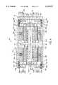
- FIG. 3Another prior art reciprocating compressor 58 is depicted in FIG. 3, wherein a moveable assembly is axially reciprocated within a housing 60 by a linear motor.
- the moveable assemblyincludes a moveable mount 62 axially moveable within housing 60, a piston 64 fixed to a center of the moveable mount 62, and an armature 66 fixed to an edge of the moveable mount 62 and carrying a moveable current coil 68 concentric to the piston 64.
- a cylinder 70 fixed and centered within housing 60is concentric to piston 64.
- a plurality of electrically conductive coil springs 71typically four, retained between moveable mount 62 and an end 72 of housing 60, provide axial alignment of the moveable assembly within housing 60.
- a plurality of inner coil springs 74assist in this axial alignment of the moveable assembly, and additionally provide a small measure of radial support therefore.
- a guide pin 76constrains the moveable assembly from rotation about a longitudinal axis of the compressor.
- the linear motor for reciprocating the moveable assemblyincludes moveable current coil 68 and permanent magnet 78 fixed within the housing proximate moveable current coil 68. To operate the linear motor, drive current is supplied to moveable current coil 68 through the electrically conductive coil springs 71. Reciprocation of piston 64 compresses a working fluid within a compression space 77 to displace the working fluid through a discharge passageway 79.
- Another object of the present inventionis to supply an electric current to a moveable current coil of a linear motor within a housing of a reciprocating compressor with an integrated flexure spring and circuit.
- a further object of the present inventionis to provide at least two electrically isolated current paths between an external source of electrical current and a moveable current coil of a linear motor within a housing of a reciprocating compressor with an integrated flexure spring and circuit.
- a new and improved reciprocating compressorincluding an electric motor having fixed and moveable components within a housing for reciprocating a moveable assembly, to compress a working fluid within a variable volume compression chamber within the housing.
- an integrated flexure spring and circuitconnected between the housing and the moveable assembly axially and radially centers the moveable assembly within the housing, and additionally, supplies an electric current to a moveable current coil of the electric motor associated with the moveable assembly.
- the moveable assemblyis axially reciprocated against a restoring force of the integrated flexure spring and circuit responsive to an axial force exerted on the moveable assembly by the electric motor when the electric current is supplied to the moveable current coil via the integrated flexure spring and circuit.
- the integrated flexure spring and circuitincludes a substantially planar, resilient flexure spring having an outer rim, an inner hub and a resilient support member coupled between the outer rim and the inner hub.
- at least two flexible, electrical conductorssuch as conductive printed circuits or tracks, are fixed to the flexure spring and are electrically isolated therefrom and from each other, and through such electrical conductors, electric current is supplied to a pair of electrical terminals of the moveable current coil of the electric motor.
- the moveable assemblyincludes a moveable cylinder fixed to the inner hub of the integrated flexure spring and circuit.
- the moveable cylinderis thus suspended and centered within the housing by the integrated flexure spring and circuit.
- the moveable cylindersurrounds a central piston fixed within the housing.
- the variable volume compression chamberis formed between the piston and the cylinder, and the working fluid within the chamber is compressed responsive to the reciprocation of the moveable assembly because of relative displacement between the piston and the cylinder.
- the moveable assemblyincludes a moveable piston fixed to the inner hub of the integrated flexible spring and circuit, and suspended thereby within the housing. As the piston is reciprocated, a free end of the piston compresses the working fluid within the variable volume compression chamber.
- the foregoing objects of the present inventionare also achieved by a reciprocating compressor adapted to be responsive to an electric current applied to a fixed terminal of the reciprocating compressor.
- the reciprocating compressorincludes a housing and a reciprocating electric motor within the housing.
- the electric motorincludes components fixed within the housing and moveable components connected to reciprocate a moveable assembly coacting with at least one variable volume chamber formed within the housing to compress a working fluid supplied to the chamber.
- a resilient springis connected between the housing and the moveable assembly to resiliently suspend and center the moveable assembly and the moveable components within the housing.
- a flexible electrical conductoris fixed to the resilient spring and electrically isolated therefrom to supply the electric current applied to the fixed terminal to an electrical terminal of the electric motor.
- the foregoing objects of the present inventionare also achieved by an integrated flexure spring and circuit for use in a reciprocating compressor.
- the integrated flexure spring and circuitincludes a substantially planar, resilient flexure spring having an outer rim, an inner hub and a resilient support member coupled between the outer rim and the inner hub.
- the integrated flexure springalso includes a flexible, electrical conductor fixed to the flexure spring and electrically isolated therefrom.
- the foregoing objects of the present inventionare also achieved by a method of operating a reciprocating compressor for compressing a working fluid, wherein the reciprocating compressor includes a housing and a moveable assembly reciprocated with an electric motor disposed in the housing.
- the methodincludes positioning and centering the moveable assembly axially and radially within the housing with a resilient spring.
- the methodalso includes supplying an electric current to the electric motor with the resilient spring.
- FIG. 1is a cross-sectional longitudinal view of a prior art reciprocating compressor having flexure bearings.
- FIG. 2Ais an elevational front view of a prior art flexure spring used in the reciprocating compressor of FIG. 1.
- FIG. 2Bis an elevational side view of the prior art flexure spring of FIG. 2A.
- FIG. 3is a cross-sectional longitudinal view of a prior art reciprocating compressor having electrically conductive coil springs.
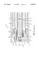
- FIG. 4is a cross-sectional longitudinal view of an embodiment of a reciprocating compressor in accordance with the present invention.
- FIG. 5Ais an elevational front view of an embodiment of an integrated flexure spring and circuit in accordance with the present invention.
- FIG. 5Bis an elevational top view of the integrated flexure spring and circuit of FIG. 5A.
- FIG. 5Cis a cross-sectional view of a layered construction of the integrated flexure spring and circuit of FIG. 5A.
- FIG. 6is a cross-sectional longitudinal view of an alternative embodiment of a reciprocating compressor in accordance with the present invention.
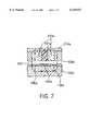
- FIG. 7is a cross-sectional longitudinal view of a first linear motor of the reciprocating compressor of FIG. 4.
- FIG. 4is an illustration of a preferred embodiment of a reciprocating compressor 80 constructed in accordance with the principles of the present invention.
- Reciprocating compressor 80includes a cylindrical, pressurized motor housing 82 having a first or left housing section 84a and a second or right housing section 84b of preferably mirror image construction to each other.
- Housing 82is made from a metal, preferably aluminum. Note that similar, i.e., corresponding, components within first and second housings 84a,84b are identified with like reference numerals containing the respective further designations "a” and "b".
- End cap 83 and a sealing ring seal 85b seal housing 84bseal housing 84b, and similarly, an end cap, not shown, and a sealing ring 85a seal housing 84a.
- End cap 83is made from a metal, preferably aluminum, and sealing rings 85a,85b are made from a rubber composition.
- a fixed central piston 86fixed at a periphery thereof to housing 82, includes a cylindrically shaped first piston end 88a and a cylindrically shaped second piston end 88b disposed respectively within housing sections 84a,84b and in fluid communication with a transversely, i.e., radially, extending discharge passage or through bore 90 through an axial through bore 92.
- Piston 86is made from a metal, preferably aluminum, and in one embodiment, the piston is integrally formed with housing 82, e.g., the housing and fixed piston can be machined from a single block of aluminum.
- a plastic sleeve or spacer 93a and a plastic sleeve or spacer 93bare fixed to respective outer surfaces of fixed piston ends 88a,88b.
- a moveable cylinder 94a and a moveable cylinder 94brespectively are adjacent to and concentric with fixed plastic sleeves 93a,93b and fixed piston ends 88a,88b to respectively define a compressor chamber 98a and a compressor chamber 98b there between.
- Moveable cylinders 94a,94bare made from a nonmagnetic metal, such as non-magnetic stainless steel.
- a cylindrically-shaped inner surface of each of moveable cylinders 94a,94bforms a clearance seal with an opposing, outer bearing surface of a respective one of fixed plastic sleeves 93a,93b, i.e., the inner surfaces of the moveable cylinders are in respective sliding and fluid sealing contact with the outer bearing surfaces of the plastic sleeves.
- Each of cylinders 94a,94bis reciprocated with a linear motor to alternately compress a working fluid within respective compression chambers 98a,98b. Alternate compression of the working fluid is a result of electrically induced deflection of a unique integrated flexure spring and circuit, a pair of which are generally designated with respect to reference numerals 100 and 102, operatively attached to a linear motor for movement therewith.
- a first linear motor disposed within first housing section 84aincludes a cylindrically-shaped moveable armature 104a, made from a ferromagnetic material, which is fixed to an outer surface of associated cylinder 94a.
- a moveable current coil 106ais in turn attached to an outer surface of moveable armature 104a and defines an air gap 108a with an inner surface of a cylindrical, i.e., ring-shaped, inner fixed magnet 110a.
- Moveable current coil 106aincludes a pair of electrically coupled coil windings axially spaced by a plastic, ring-shaped spacer 109a fixed to the outer surface of moveable armature 104a.
- the axially spaced coil windingsare wound in opposite directions, e.g., in respective clockwise and counter-clockwise directions, about moveable armature 104a.
- a second linear motor within housing section 84bincludes likely, i.e., mirror image, components.
- Moveable current coils 106a,106bare electrically connected in parallel.
- moveable cylinders 94a,94b with respective moveable armatures 104a,104b and respective moveable current coils 106a,106brespectively form a first moveable assembly and a second moveable assembly suspended within respective motor housing sections 84a,84b for reciprocating axial displacement along a longitudinal axis 112 of motor housing 82.
- a pair of axial clearance gaps 109a,109b between radially extending portions of fixed piston 86 and respective end faces of the first and second moveable assembliespermit reciprocating movement of the moveable assemblies through a distance equal to the axial clearance of the gaps.
- Inner fixed magnet 110ais fixed to an inner surface of a cylindrically-shaped, ferromagnetic, outer pole piece 114a of the first linear motor. Outer pole piece 114a is in turn fixed to an inner surface of first housing section 84a.
- Inner fixed magnet 110aincludes a pair of radially polarized ring magnets, axially spaced by a plastic spacer 111a. Fixed magnet 110a and outer pole piece 114a together form a magnet assembly surrounding moveable current coil 106a. Similar components are disposed within second housing section 84b.
- Each magnet assemblyis positioned sufficiently close to an associated one of moveable current coils 106a,106b within associated first and second housing sections 84a,84b, to facilitate magnetic coupling between the magnet assemblies and the moveable current coils when the coils carry motor drive current therein.
- the small clearance or air gaps 108a,108b between the magnet assemblies and associated moveable current coils 106a,106bpermit frictionless relative movement.
- the magnetic circuit formed within the first linear motoris depicted in FIG. 7.
- the spaced ring magnets of fixed magnet 110aare radially polarized in opposite North (N)--South (S) directions.
- Magnetic fluxcirculates through the components of the linear motor in a clockwise direction along a circuitous flux path 200, as follows:
- radial polarization of fixed magnet 110aas compared to an alternative, such as axial polarization thereof, advantageously maximizes the magnetic flux density crossing air gap 108a and intersecting the spaced coil windings of moveable current coil 106a.
- Such radial polarizationthus leads to a more compact, lower weight configuration for reciprocating compressor 80; an important consideration for airborne applications of the compressor.
- an important and advantageous feature of the reciprocating compressor 80is integrated flexure spring and circuit 100 fixedly mounted along its outer periphery within an end 116a of housing 82.
- integrated flexure spring and circuit 102is fixedly mounted along its outer periphery within an end 116b of housing 82.
- springs 100,102are mounted parallel to each other with a pair of spring supports 118a and a pair of spring supports 118b, respectively.
- Spring supports or mounts 118a,118bare electrically insulating and preferably made from a plastic-reinforced glass composition.
- Axially spaced spring supports 118a,118bare attached to respective inner surfaces of housing ends 116a,116b, with the associated spring periphery sandwiched there between.
- a hub 120 (see FIG. 5A) formed in the center of spring 100is attached to an extended end portion 119a of cylinder 94a, and similarly, a hub 120 formed in the center of spring 102 is attached to an extended end portion 119b of cylinder 94b.
- springs 100,102respectively center and suspend the first and second moveable assemblies, i.e., associated moveable cylinders 94a,94b, moveable armatures 104a,104b, and moveable current coils 106a,106b fixed thereto, for reciprocating axial displacement thereof.
- springs 100,102align the respective first and second moveable assemblies in both axial and radial directions within motor housing 82.
- spring 100(and spring 102) is in the form of a substantially planar flexure spring, made from spring steel, having an annular outer rim portion 126, inner hub portion 120, and a resilient support member coupled between the outer rim and inner hub.
- Inner hub portion 120includes a central through aperture 121.
- the resilient support memberincludes a plurality of resilient spring arms 128A, 128B and 128C coupled between outer rim 126 and inner hub 120, and extending in both circumferential and radial directions there between (the designations "A"-"C" distinguish like components of the one spring, and are not to be confused with the designations "a","b” used to distinguish like components within housings sections 84a,84b).
- a plurality of through apertures 139separate resilient spring arms 128A-128C, inner hub 120 and outer rim 126.
- a plurality of flexible, electrically conductive printed circuits or tracks 130A, 130B and 130Care respectively fixedly applied, i.e., bonded, to electrically insulated surfaces of spring arms 128A-128C.
- An electrically insulating layer 184(FIG. 5C) bonded to a surface of each spring arm 128A-128C of the flexure spring ensures printed circuits 130A-130C are each electrically isolated from the underlying flexure spring and from each other. Electrically insulating layer 184 is preferably made from a plastic composition.
- Printed circuit or track 130Aincludes an outer terminal portion 132A coincident with a portion of outer rim 126, an inner terminal portion 134A coincident with a portion of inner hub 120, and a track portion 136A traversing a length of resilient spring arm 128A between outer and inner terminal portions 132A and 134A.
- Printed circuits 130B and 130Cinclude similarly arranged terminal and track portions.
- a solder joint 129Ajoins a first end of an electrical inner lead 150a to inner terminal portion 134A of printed circuit 130A.
- a solder joint 129Cjoins a first end of an electrical inner lead 151a to inner terminal portion 134C of printed circuit track 130C.
- integrated flexure spring and circuit 100includes at least two spring arms and at least two corresponding printed circuits or tracks for establishing at least two electrically isolated conductive paths.
- the third printed circuite.g., printed circuit 130B of spring 100 (and 102), enhances flexibility in assembling reciprocating compressor 80.
- spring 100can be rotated as necessary to align any two of the three outer terminal portions 132A-132C with a corresponding pair of fixed terminals of reciprocating compressor 80, during assembly thereof.
- each resilient support arm of the resilient support membercan be substantially radially directed, spiral-like, or can follow a serpentine path between outer rim 126 and inner hub 120.
- the number and widths of the support armscan be varied.
- numerous alternative arrangements of the flexible printed circuit componentare also possible.
- the arrangement of the electrically conductive tracks, i.e., the number, widths, and locations of the electrically conductive trackscan be varied to suit the requirements of a particular application or use of spring 100.
- an electrically conductive wire or cable, or other flexible conductoris integrally bonded to the surface of the spring arm.
- the electrically conductive flexible printed circuit, wire or cablecan be substantially encased or embedded within spring 100, with only inner and outer terminal portions thereof exposed at the surface of spring 100 for electrical connection.
- outer rim 126 of spring 100is secured to housing end 116a of the housing 82 by a pair of annular spring mounts 118a.
- the spring 100is thus coupled to the housing end 116a of housing 82 so as to extend across housing end 116a in a transverse planar direction, with an exterior surface of spring 100 having the printed circuit applied thereto facing away from an interior of the motor housing.
- first piston end 88a, a bolt 142a, inserted through central aperture 121 of inner hub 120 of spring 100secures a compression plug 140a to an interior surface of the spring at the inner hub thereof.
- Compression plug 140ais made from a non-magnetic metal; preferably non-magnetic stainless steel.
- Extended end portion 119a of cylinder 100 surrounding compression plug 140ais also fixed to the interior surface of spring 100 at inner hub 120 thereof. In this manner moveable cylinder 94a is suspended within first housing section 84a by spring 100. Variable volume compression space 98a in fluid communication with axial through bore 92 is formed between first piston end 88a and compression plug 140a.
- Spring 102is similarly coupled to and extends transversely across housing end 116b of motor housing 82. Since components within the second housing correspond to the aforementioned components in the first housing, moveable cylinder 94b is suspended within second housing section 84b by spring 102. Springs 100,102 center and suspend respective moveable cylinders 94a,94b and thus, the first and second moveable assemblies within motor housing 82. A pair of clearance gaps 141a and a pair of clearance gaps 141b respectively straddle springs 100,102 and permit interference-free reciprocation thereof.
- the first linear motorincluding moveable current coil 106a and the associated fixed magnet assembly, axially displaces the first moveable assembly suspended within first housing section 84a.
- the second linear motorincluding moveable current coil 106b and the associated fixed magnet assembly, axially displaces the second moveable assembly suspended within second housing section 84b.
- the first linear motoris driven responsive to a sinusoidal, i.e., alternating, motor drive current supplied from an external current source, not shown, to a circuit board 144a secured to first end 116a of motor housing 82.
- the particulars of the external current sourceare known in the art and are not important to the inventive concept of the present invention, so long as the motor drive current supplied thereby produces the required reciprocating displacement of the moveable assembly.
- a pair of short, electrical outer leads 146a,147acarry the motor drive current (supplied to circuit board 144a from the external current source) from circuit board 144a to a respective pair of electrical housing terminals 148a,149a fixed to a periphery of first end 116a of motor housing 82, i.e., fixed within spring mounts 118a.
- Housing terminals 148a,149aare in registration and electrical contact with respective outer terminal portions 132A,132C (FIG. 5A) of respective electrically conductive tracks 130A,130C of spring 100.
- a pair of short, flexible electrical inner leads 150a,151awhich can be, for example, a pair of wires or flat cables, electrically couple respective inner terminal portions 134A,134C (of respective tracks 130A,130C) at inner hub 120 of spring 100, to a respective pair of electrical terminals of moveable coil 106a.
- inner leads 150a,151aare soldered to respective inner terminal portion 134A,134C of spring 100 to effect electrical connections thereto, while a second end of each of inner leads 150a,151a is connected to a respective one of the pair of electrical terminals of moveable current coil 106a.
- electrically isolated, conductive pathsare respectively established between housing terminals 148a,149a and the electrical terminals of moveable current coil 106a through respective electrically conductive tracks 130A,130C applied to the exterior surface of spring 100 (and through respective inner leads 150a,151a).
- the electrical coupling arrangement just described with respect to components within first housing section 84ais replicated within second housing section 84b, as depicted in FIG. 4. Therefore, a duplicative textual description of the electrical coupling arrangement within second housing 84b is herein omitted for the sake of descriptive brevity and clarity.
- springs 100,102are arranged and operate similarly in respective housing sections 84a,84b, e.g., motor drive current is supplied from the external source to moving coil 106b via spring 102 in the same manner as motor drive current is supplied from the external source to moving coil 106a via spring 100.
- the external source of currentsupplies a sinusoidal motor drive current to moveable coils 106a,106b of the respective first and second linear motors through respective springs 100,102, as described above.
- Each moveable assemblyis displaced from an initial rest position, i.e., the neutral or centered position depicted in FIG. 5, in first and second opposing axial directions against a restoring force of a respective one of springs 100,102 responsive to a respective axial force exerted on each moveable assembly.
- the axial forceresults from a magnetic interaction induced between the magnet assembly and the moveable current coil of the moveable assembly when the motor drive current is supplied to the electrical terminals of the moveable current coil. Because of the mirror-image arrangement of components within first and second housing sections 84a,84b, the first and second moveable assemblies (in the respective first and second housing sections) reciprocate in anti-phase or opposite axial directions, i.e., the moveable assemblies are axially displaced 180° out of phase with respect to each other.
- each respective compression space 98a,98balternately expands and contracts since first and second piston ends 88a,88b are fixed within the motor housing 82.
- the typically gaseous working fluid occupying the compression spaces 98a,98bis thus alternately displaced from the compression spaces into and through axial and exit through bores 92,90 within piston 86.
- outer rim 126is stationary while inner hub 120 reciprocates in the axial direction responsive to a driving force applied to inner hub 120, i.e., inner hub 120 is displaced by an axial force from an initial rest position in a transverse plane (depicted in FIG. 4, and by the solid lines in FIG. 5B) in first and second opposing axial directions (depicted by the arrows at either end of central axis line 112) against a restoring force of the resilient support member, i.e., of each of resilient spring arms 128A-128C.
- a driving force applied to inner hub 120i.e., inner hub 120 is displaced by an axial force from an initial rest position in a transverse plane (depicted in FIG. 4, and by the solid lines in FIG. 5B) in first and second opposing axial directions (depicted by the arrows at either end of central axis line 112) against a restoring force of the resilient support member, i.e., of each of resilient spring arms 128A-128C
- outer rim 126 and inner hub 120remain, for the most part, flat and parallel during operation, while each of resilient spring arms 128A-128C bends out of the initial rest position to accommodate the axial displacement of inner hub 120, e.g., to the dashed line positions indicated in FIG. 5B.
- the planar construction of spring 100naturally biases each of resilient spring arms 128A-128C against the axial displacement of inner hub 120 away from the initial rest position, and thus, each resilient spring arm exerts a restoring force toward the initial rest position whenever the inner hub is so displaced.
- a preferable peak amplitude of axial displacement of hub 120 from the rest positionis approximately 2/10 of an inch, i.e., a peak amplitude of 2/10 of an inch in each opposing axial direction, for a total peak-to-peak amplitude of 4/10 of an inch.
- Such displacementlimits bending or flexing induced in any localized area of the electrically conductive printed circuit, and thus, drastically reduces stress related failure of the printed circuit.
- the magnitude of the restoring forceis determined by an axial stiffness of the spring 100.
- spring 100is constructed to have a radial, i.e., transverse, stiffness that is substantially greater than the axial stiffness of the spring 100.
- springs 100,102perform two critical functions. First, springs 100,102 respectively locate the first and second moveable assemblies and the moveable components of the first and second linear motors (i.e., moveable coils 106a,106b) within motor housing 82 both axially and radially. Second, springs 100,102 and specifically, electrically conductive tracks 130A-130C applied thereto, serve as part of a current coupling mechanism through which motor drive current is transferred between the external source of motor drive current and respective moveable current coils 106a,106b. Advantages of reciprocating compressor 80 realized through use of springs 100,102 therein include the following:
- a single springaccommodates a pair of isolated, electrically conductive printed circuits for conducting motor drive current to an associated moveable current coil
- springs 100,102are typically less expensive than an equivalent number of conductive coil springs, i.e., the number of coil springs needed to fulfill the functionality provided by the integral spring device;
- reciprocating compressor 80 of FIG. 4includes moveable cylinders 94a,94b and a fixed piston 86.
- FIG. 6another embodiment of the reciprocating compressor of the present invention is depicted in FIG. 6, wherein reciprocating compressor 160 includes a moveable rather than a fixed piston.
- the construction, arrangement and operation of the reciprocating compressor of FIG. 6are similar in some aspects to the prior art reciprocating compressor of FIG. 1, with a significant distinction and improvement; flexure bearing 44 of prior art reciprocating compressor 10 of FIG. 1 is replaced in the reciprocating compressor 160 of FIG. 6 by spring 100.
- the incorporation of spring 100obviates the need for failure prone inner lead 42 between fixed terminal 40 and moveable current coil 36.
- outer rim 126 of spring 100is secured to left housing mount 26 while inner hub 120 of spring 100 is fixed to a left end of piston 14.
- Electrical terminal 40is in registration and electrical contact with outer terminal portion 132A of electrically conductive track 130A, at outer rim 126 of spring 100.
- An electrical connection between electrical terminal 40 and an electrical terminal of moveable current coil 36 via an inner lead wire 162is constructed in the same manner as described in connection with reciprocating compressor 80 of FIG. 4. In this manner, an electrically conductive path is established between electrical terminal 40 and the electrical terminal of moveable current coil 36 through electrically conductive track 130A applied to the exterior surface of spring 100, and inner lead 162.
- another electrical coupling arrangementnot shown, similar to the arrangement just described, supplies current to another electrical terminal of current coil 36 through electrically conductive track 130C, to complete an electrical current path between current coil 36 and the external source of current.
- the external source of currentsupplies a motor drive current to the linear motor through outer lead 39, electrical terminal 40, electrically conductive track 130A applied to the exterior surface of spring 100, and inner lead 162.
- the moveable assemblyis displaced from an initial rest position, i.e., a neutral or center position depicted in FIG. 6, in first and second opposing axial directions against a restoring force of spring 100 and an associated restoring force of flexure bearing 46, responsive to an axial force exerted on the moveable assembly.
- the axial forceresults from a magnetic interaction between fixed magnet 34 and moveable current coil 36, when the motor drive current is supplied 25 to the electrical terminals of moveable current coil 36.
- an opposing piston 164is suspended within the right half of the motor housing by an associated integral spring device (and flexure bearing), and is similarly driven by an associated linear motor.
- each of the first and second moveable assemblies occupying respective housing sections 84a,84bcan be independently driven by the respective first and second linear motors.
- each of moveable current coils 106a,106bis independently supplied with an electric current from an external source.
- the laminated or layered cross-sectional construction of spring 100is depicted in FIG. 5C.
- the layered constructionincludes a resilient or springy base layer, corresponding to spring arm 128A, made from spring steel.
- An exemplary thickness of the base layeris approximately 12/1000 of an inch.
- an electrically insulating layer 184Applied to an upper surface of the resilient base layer is an electrically insulating layer 184, which is made from a plastic.
- an electrically insulating layer 184As previously described, applied or bonded to an upper surface of insulating layer 184 is the thin, flexible, electrically conductive layer, corresponding to electrically conductive track 130A.
- the conductive layeris made from a flexible, suitably durable, conductive material; preferably beryllium copper. A preferred thickness of the conductive layer is in the approximate range of three to four thousandths of an inch.
- spring 100is a composite of three layers fixed together, i.e., the spring steel base layer, plastic insulating layer 184, and the conductive layer, it is important that each of the three layers exhibit a similar thermal expansion over the operating temperature range of spring 100. Such similarity in thermal expansion minimizes destructive stresses in the spring that would otherwise arise from disparate thermal expansion between the three layers.
- a method of manufacturing or producing the layered constructionincludes the following steps:
- This step in the methodcan be effected through chemical etching.
- the integrated flexure spring and circuitis fabricated with chemical milling operations instead of mechanical deformation steps, the resulting integral spring device is advantageously produced with virtually no residual stresses therein. This increases the reliability and extends the operational life of the integrated flexure spring and circuit.
- a flexible electrically conductive wire or cableis bonded to electrically insulating layer 184 instead of the printed circuit.
- the printed circuit, wire or cableis embedded within the laminated or layered structure with only inner and outer terminal portions thereof exposed at the surface of the spring for connection with the motor terminals and inner leads of the linear motor.
Landscapes
- Engineering & Computer Science (AREA)
- Power Engineering (AREA)
- Mechanical Engineering (AREA)
- General Engineering & Computer Science (AREA)
- Reciprocating, Oscillating Or Vibrating Motors (AREA)
- Compressors, Vaccum Pumps And Other Relevant Systems (AREA)
- Connection Of Motors, Electrical Generators, Mechanical Devices, And The Like (AREA)
Abstract
Description
Claims (28)
Priority Applications (6)
| Application Number | Priority Date | Filing Date | Title |
|---|---|---|---|
| US09/292,984US6129527A (en) | 1999-04-16 | 1999-04-16 | Electrically operated linear motor with integrated flexure spring and circuit for use in reciprocating compressor |
| CA002299930ACA2299930A1 (en) | 1999-04-16 | 2000-03-03 | Electrically operated linear motor with integrated flexure spring and circuit for use in reciprocating compressor |
| EP00106259AEP1045145B1 (en) | 1999-04-16 | 2000-03-22 | Electrically operated linear motor with integrated flexure spring and circuit for use in reciprocating compressor |
| DE60020294TDE60020294T2 (en) | 1999-04-16 | 2000-03-22 | Electrically operated linear motor with integrated spiral spring and switch for use in a reciprocating compressor |
| JP2000111835AJP2000329064A (en) | 1999-04-16 | 2000-04-13 | Reciprocating motion compressor using integral deflection spring circuit and electric linear motor, and operating method thereof |
| KR1020000020096AKR20000071713A (en) | 1999-04-16 | 2000-04-17 | Reciprocating compressor and operating method the same, and electrically operated linear motor with integrated flexure spring and circuit for use in reciprocating compressor |
Applications Claiming Priority (1)
| Application Number | Priority Date | Filing Date | Title |
|---|---|---|---|
| US09/292,984US6129527A (en) | 1999-04-16 | 1999-04-16 | Electrically operated linear motor with integrated flexure spring and circuit for use in reciprocating compressor |
Publications (1)
| Publication Number | Publication Date |
|---|---|
| US6129527Atrue US6129527A (en) | 2000-10-10 |
Family
ID=23127106
Family Applications (1)
| Application Number | Title | Priority Date | Filing Date |
|---|---|---|---|
| US09/292,984Expired - LifetimeUS6129527A (en) | 1999-04-16 | 1999-04-16 | Electrically operated linear motor with integrated flexure spring and circuit for use in reciprocating compressor |
Country Status (6)
| Country | Link |
|---|---|
| US (1) | US6129527A (en) |
| EP (1) | EP1045145B1 (en) |
| JP (1) | JP2000329064A (en) |
| KR (1) | KR20000071713A (en) |
| CA (1) | CA2299930A1 (en) |
| DE (1) | DE60020294T2 (en) |
Cited By (72)
| Publication number | Priority date | Publication date | Assignee | Title |
|---|---|---|---|---|
| US20020018724A1 (en)* | 2000-02-29 | 2002-02-14 | Millet Hank E. | Compressor with control and protection system |
| US6499972B2 (en)* | 2000-05-23 | 2002-12-31 | Cryodevice Inc. | Linear compressor |
| US20030017064A1 (en)* | 2001-07-19 | 2003-01-23 | Matsushita Electric Industrial Co., Ltd. | Linear compressor |
| US20030072658A1 (en)* | 2001-10-12 | 2003-04-17 | Jung-Sik Park | Double side action type reciprocating compressor |
| US6641377B2 (en)* | 2000-11-13 | 2003-11-04 | Fuji Electric Co., Ltd. | Linear compressor with a plurality of support springs and a dual compression unit |
| US20030219350A1 (en)* | 2002-01-29 | 2003-11-27 | Marnix Meijers | Compressor cooler and its assembly procedure |
| KR100425732B1 (en)* | 2001-11-30 | 2004-04-06 | 엘지전자 주식회사 | Opposed type reciprocating compressor |
| WO2004036723A1 (en)* | 2002-10-16 | 2004-04-29 | Matsushita Refrigeration Company | Linear motor and liner compressor using the same |
| US6737780B1 (en) | 2003-02-12 | 2004-05-18 | Siemens Vdo Automotive Inc. | Electric motor magnetic flux path structure |
| US20040174076A1 (en)* | 2002-05-06 | 2004-09-09 | Knirck Jeffrey G. | Moving coil linear motor positioning stage with a concentric aperture |
| US6813225B2 (en) | 2001-08-20 | 2004-11-02 | Asm Assembly Automation Limited | Linear motor driven mechanism using flexure bearings for opto-mechanical devices |
| KR100462996B1 (en)* | 2002-08-27 | 2004-12-23 | 한국기계연구원 | Linear flexure bearing |
| US7032400B2 (en) | 2004-03-29 | 2006-04-25 | Hussmann Corporation | Refrigeration unit having a linear compressor |
| US20070052144A1 (en)* | 2004-09-08 | 2007-03-08 | Equipment Solutions, Inc. | High stiffness flexure |
| US7290398B2 (en) | 2003-08-25 | 2007-11-06 | Computer Process Controls, Inc. | Refrigeration control system |
| US7412842B2 (en) | 2004-04-27 | 2008-08-19 | Emerson Climate Technologies, Inc. | Compressor diagnostic and protection system |
| US20080282707A1 (en)* | 2007-05-16 | 2008-11-20 | Raytheon Company | Cryocooler with moving piston and moving cylinder |
| US7594407B2 (en) | 2005-10-21 | 2009-09-29 | Emerson Climate Technologies, Inc. | Monitoring refrigerant in a refrigeration system |
| US7596959B2 (en) | 2005-10-21 | 2009-10-06 | Emerson Retail Services, Inc. | Monitoring compressor performance in a refrigeration system |
| US7644591B2 (en) | 2001-05-03 | 2010-01-12 | Emerson Retail Services, Inc. | System for remote refrigeration monitoring and diagnostics |
| US7665315B2 (en) | 2005-10-21 | 2010-02-23 | Emerson Retail Services, Inc. | Proofing a refrigeration system operating state |
| US7752853B2 (en) | 2005-10-21 | 2010-07-13 | Emerson Retail Services, Inc. | Monitoring refrigerant in a refrigeration system |
| US7752854B2 (en) | 2005-10-21 | 2010-07-13 | Emerson Retail Services, Inc. | Monitoring a condenser in a refrigeration system |
| US7885961B2 (en) | 2005-02-21 | 2011-02-08 | Computer Process Controls, Inc. | Enterprise control and monitoring system and method |
| US8160827B2 (en) | 2007-11-02 | 2012-04-17 | Emerson Climate Technologies, Inc. | Compressor sensor module |
| WO2012064785A1 (en)* | 2010-11-08 | 2012-05-18 | Mark Olsson | Slim profile magnetic user interface devices |
| US20120177513A1 (en)* | 2009-07-08 | 2012-07-12 | Whirlppol S.A. | Linear compressor |
| US8254045B1 (en) | 2009-06-05 | 2012-08-28 | Benner Jr William R | High-speed Z-axis focusing device and associated methods |
| CN102780315A (en)* | 2012-08-15 | 2012-11-14 | 张正泉 | Hydraulic or pneumatic device composed of linear motor |
| US8393169B2 (en) | 2007-09-19 | 2013-03-12 | Emerson Climate Technologies, Inc. | Refrigeration monitoring system and method |
| US8473106B2 (en) | 2009-05-29 | 2013-06-25 | Emerson Climate Technologies Retail Solutions, Inc. | System and method for monitoring and evaluating equipment operating parameter modifications |
| US8495886B2 (en) | 2001-05-03 | 2013-07-30 | Emerson Climate Technologies Retail Solutions, Inc. | Model-based alarming |
| US8590325B2 (en) | 2006-07-19 | 2013-11-26 | Emerson Climate Technologies, Inc. | Protection and diagnostic module for a refrigeration system |
| US20140020555A1 (en)* | 2010-12-27 | 2014-01-23 | Marcio Silverio | Piston assembly for alternative compressor |
| CN103671012A (en)* | 2013-11-21 | 2014-03-26 | 中国科学院上海技术物理研究所 | Oppositely-arranged moving coil linear compressor adopting long-coil radial magnetization and manufacturing method |
| US8700444B2 (en) | 2002-10-31 | 2014-04-15 | Emerson Retail Services Inc. | System for monitoring optimal equipment operating parameters |
| US8964338B2 (en) | 2012-01-11 | 2015-02-24 | Emerson Climate Technologies, Inc. | System and method for compressor motor protection |
| US8974573B2 (en) | 2004-08-11 | 2015-03-10 | Emerson Climate Technologies, Inc. | Method and apparatus for monitoring a refrigeration-cycle system |
| CN104405615A (en)* | 2014-10-16 | 2015-03-11 | 中国科学院上海技术物理研究所 | Overall scaling method for developing opposed movable coil type linear compressors |
| US20150084725A1 (en)* | 2012-01-18 | 2015-03-26 | Roland Aigner | Linear bearing, and solenoid comprising such a linear bearing |
| US20150226197A1 (en)* | 2014-02-10 | 2015-08-13 | General Electric Company | Linear compressor |
| US9140728B2 (en) | 2007-11-02 | 2015-09-22 | Emerson Climate Technologies, Inc. | Compressor sensor module |
| US9248232B2 (en) | 2009-11-30 | 2016-02-02 | Roche Diabetes Care, Inc. | Analyte monitoring and fluid dispensing system |
| US9285802B2 (en) | 2011-02-28 | 2016-03-15 | Emerson Electric Co. | Residential solutions HVAC monitoring and diagnosis |
| US20160097387A1 (en)* | 2014-10-07 | 2016-04-07 | Sumitomo Heavy Industries, Ltd. | Support structure for linear-compressor moving component, linear compressor, and cryogenic refrigerator |
| US9310094B2 (en) | 2007-07-30 | 2016-04-12 | Emerson Climate Technologies, Inc. | Portable method and apparatus for monitoring refrigerant-cycle systems |
| US9310439B2 (en) | 2012-09-25 | 2016-04-12 | Emerson Climate Technologies, Inc. | Compressor having a control and diagnostic module |
| US9423894B2 (en) | 2010-12-02 | 2016-08-23 | Seesaw, Inc. | Magnetically sensed user interface devices |
| US9480177B2 (en) | 2012-07-27 | 2016-10-25 | Emerson Climate Technologies, Inc. | Compressor protection module |
| US9551504B2 (en) | 2013-03-15 | 2017-01-24 | Emerson Electric Co. | HVAC system remote monitoring and diagnosis |
| US9638436B2 (en) | 2013-03-15 | 2017-05-02 | Emerson Electric Co. | HVAC system remote monitoring and diagnosis |
| US9678577B1 (en) | 2011-08-20 | 2017-06-13 | SeeScan, Inc. | Magnetic sensing user interface device methods and apparatus using electromagnets and associated magnetic sensors |
| US9690390B2 (en) | 2013-05-17 | 2017-06-27 | SeeScan, Inc. | User interface devices |
| US9765979B2 (en) | 2013-04-05 | 2017-09-19 | Emerson Climate Technologies, Inc. | Heat-pump system with refrigerant charge diagnostics |
| US9823632B2 (en) | 2006-09-07 | 2017-11-21 | Emerson Climate Technologies, Inc. | Compressor data module |
| US10041713B1 (en) | 1999-08-20 | 2018-08-07 | Hudson Technologies, Inc. | Method and apparatus for measuring and improving efficiency in refrigeration systems |
| US10055512B2 (en) | 2012-07-16 | 2018-08-21 | Omc2 Llc | System and method for CNC machines and software |
| US10100897B2 (en)* | 2014-11-26 | 2018-10-16 | Sumitomo Riko Company Limited | Vibration-damping electromagnetic actuator, active fluid-filled vibration-damping device and active vibration-damping device using the same |
| US10121617B2 (en) | 2010-08-20 | 2018-11-06 | SeeScan, Inc. | Magnetic sensing user interface device methods and apparatus |
| US10203717B2 (en) | 2010-10-12 | 2019-02-12 | SeeScan, Inc. | Magnetic thumbstick user interface devices |
| CN109804162A (en)* | 2016-10-14 | 2019-05-24 | 日立汽车系统株式会社 | Linearkompressor and equipment equipped with Linearkompressor |
| US10312788B2 (en)* | 2016-07-21 | 2019-06-04 | AAC Technologies Pte. Ltd. | Linear vibration motor |
| US10422329B2 (en) | 2017-08-14 | 2019-09-24 | Raytheon Company | Push-pull compressor having ultra-high efficiency for cryocoolers or other systems |
| US10436488B2 (en) | 2002-12-09 | 2019-10-08 | Hudson Technologies Inc. | Method and apparatus for optimizing refrigeration systems |
| US10488090B2 (en) | 2013-03-15 | 2019-11-26 | Emerson Climate Technologies, Inc. | System for refrigerant charge verification |
| US10528074B1 (en) | 2009-04-15 | 2020-01-07 | SeeScan, Inc. | Magnetic manual user interface devices |
| US10788901B2 (en) | 2010-05-18 | 2020-09-29 | SeeScan, Inc. | User interface devices, apparatus, and methods |
| US20210399617A1 (en)* | 2019-03-12 | 2021-12-23 | Alps Alpine Co., Ltd. | Electromagnetic drive device and operation device |
| US20220196010A1 (en)* | 2020-12-18 | 2022-06-23 | Lg Electronics Inc. | Elastic body and linear compressor including the same |
| US20230006528A1 (en)* | 2018-05-21 | 2023-01-05 | Apple Inc. | Double helix actuator with magnetic sections having alternating polarities |
| US20230178952A1 (en)* | 2021-12-08 | 2023-06-08 | Eagle Technology, Llc | Optical system for use with a vacuum chamber and associated method |
| US20240278274A1 (en)* | 2022-01-12 | 2024-08-22 | Shenzhen Xuanda Electronics Co., Ltd | Frequency-adjustable water dripping device |
Families Citing this family (32)
| Publication number | Priority date | Publication date | Assignee | Title |
|---|---|---|---|---|
| US6830562B2 (en) | 2001-09-27 | 2004-12-14 | Unomedical A/S | Injector device for placing a subcutaneous infusion set |
| DE60304681T2 (en) | 2002-02-12 | 2007-01-25 | Unomedical A/S | INFUSION DEVICE WITH NADELSCHUTZHÜLSE |
| US20040051019A1 (en) | 2002-09-02 | 2004-03-18 | Mogensen Lasse Wesseltoft | Apparatus for and a method of adjusting the length of an infusion tube |
| EP1534378B1 (en) | 2002-09-02 | 2008-12-31 | Unomedical A/S | A device for subcutaneous administration of a medicament to a patient and tubing for same |
| AU2003258487A1 (en) | 2002-09-02 | 2004-03-19 | Unomedical A/S | A device for subcutaneous administration of a medicament to a patient |
| AU2003257754A1 (en) | 2002-09-02 | 2004-03-19 | Unomedical A/S | An apparatus and a method for adjustment of the length of an infusion tubing |
| DK200201823A (en) | 2002-11-26 | 2004-05-27 | Maersk Medical As | Connection piece for a hose connection |
| US20040158202A1 (en) | 2003-02-12 | 2004-08-12 | Soren Jensen | Cover |
| USD576267S1 (en) | 2003-10-15 | 2008-09-02 | Unomedical A/S | Medical infusion device |
| USD554253S1 (en) | 2003-10-15 | 2007-10-30 | Unomedical A/S | Medical infusion device |
| USD579541S1 (en) | 2003-10-15 | 2008-10-28 | Unomedical A/S | Medical insertion device |
| MXPA06010784A (en) | 2004-03-26 | 2006-12-15 | Unomedical As | Injector device for infusion set. |
| KR100608681B1 (en)* | 2004-07-26 | 2006-08-08 | 엘지전자 주식회사 | Reciprocating compressor |
| JP4617760B2 (en)* | 2004-07-30 | 2011-01-26 | ミツミ電機株式会社 | Autofocus actuator |
| JP4617759B2 (en)* | 2004-07-30 | 2011-01-26 | ミツミ電機株式会社 | Autofocus actuator |
| US8062250B2 (en) | 2004-08-10 | 2011-11-22 | Unomedical A/S | Cannula device |
| US7867199B2 (en) | 2004-12-10 | 2011-01-11 | Unomedical A/S | Inserter |
| DE102004061940A1 (en) | 2004-12-22 | 2006-07-06 | Aerolas Gmbh, Aerostatische Lager- Lasertechnik | Piston-cylinder-unit for use in compressor, has fluid storage provided between piston and cylinder and formed by fluid discharged from discharging nozzles into storage opening under pressure |
| DE102004062301A1 (en)* | 2004-12-23 | 2006-07-13 | BSH Bosch und Siemens Hausgeräte GmbH | Linear compressor and drive unit for it |
| DE102004062302A1 (en) | 2004-12-23 | 2006-07-13 | BSH Bosch und Siemens Hausgeräte GmbH | Linear compressor and drive unit for it |
| DE102004062298A1 (en)* | 2004-12-23 | 2006-07-13 | BSH Bosch und Siemens Hausgeräte GmbH | linear compressor |
| DE102004062307A1 (en) | 2004-12-23 | 2006-07-13 | BSH Bosch und Siemens Hausgeräte GmbH | linear compressor |
| CA2612664A1 (en) | 2005-06-28 | 2007-01-04 | Unomedical A/S | Packing for infusion set and method of applying an infusion set |
| EP1762259B2 (en) | 2005-09-12 | 2025-01-01 | Unomedical A/S | Inserter for an infusion set with a first and second spring units |
| USD655807S1 (en) | 2005-12-09 | 2012-03-13 | Unomedical A/S | Medical device |
| GB2436400B (en)* | 2006-03-25 | 2011-11-30 | Hymatic Eng Co Ltd | Electromagnetic Transducer Apparatus |
| US8615993B2 (en)* | 2009-09-10 | 2013-12-31 | Global Cooling, Inc. | Bearing support system for free-piston stirling machines |
| JP2012151954A (en)* | 2011-01-18 | 2012-08-09 | Toshiba Mach Co Ltd | Linear motor |
| FR3039694B1 (en)* | 2015-07-27 | 2018-06-15 | Hutchinson | ACTIVE VIBRATION CONTROL DEVICE |
| WO2019160537A1 (en)* | 2018-02-14 | 2019-08-22 | Dresser-Rand Company | Modular linear reciprocating compressor |
| JP7428510B2 (en)* | 2019-12-09 | 2024-02-06 | 住友重機械工業株式会社 | Cryogenic refrigerators, flexure bearings and linear compressors for cryogenic refrigerators |
| EP4074071A1 (en)* | 2019-12-11 | 2022-10-19 | Lofelt GmbH | Linear vibration actuator having moving coil and moving magnet |
Citations (22)
| Publication number | Priority date | Publication date | Assignee | Title |
|---|---|---|---|---|
| US3910729A (en)* | 1973-06-25 | 1975-10-07 | Air Prod & Chem | Compressor |
| US4067667A (en)* | 1974-05-08 | 1978-01-10 | Mechanical Technology Incorporated | Controlled stroke electrodynamic oscillating motor compressor |
| US4179630A (en)* | 1976-11-04 | 1979-12-18 | Tecumseh Products Company | Linear compressor |
| US4353220A (en)* | 1980-06-17 | 1982-10-12 | Mechanical Technology Incorporated | Resonant piston compressor having improved stroke control for load-following electric heat pumps and the like |
| US4389849A (en)* | 1981-10-02 | 1983-06-28 | Beggs James M Administrator Of | Stirling cycle cryogenic cooler |
| US4713939A (en)* | 1986-05-23 | 1987-12-22 | Texas Instruments Incorporated | Linear drive motor with symmetric magnetic fields for a cooling system |
| US4750871A (en)* | 1987-03-10 | 1988-06-14 | Mechanical Technology Incorporated | Stabilizing means for free piston-type linear resonant reciprocating machines |
| US4781546A (en)* | 1987-03-10 | 1988-11-01 | Mechanical Technology Incorporated | Linear resonant reciprocating machines |
| US4836757A (en)* | 1987-02-13 | 1989-06-06 | Mechanical Technology Incorporated | Pressure actuated movable head for a resonant reciprocating compressor balance chamber |
| US4872313A (en)* | 1987-09-04 | 1989-10-10 | Mitsubishi Denki Kabushiki Kaisha | Gas cycle machine |
| US5032772A (en)* | 1989-12-04 | 1991-07-16 | Gully Wilfred J | Motor driver circuit for resonant linear cooler |
| US5257915A (en)* | 1992-04-03 | 1993-11-02 | General Electric Company | Oil free linear motor compressor |
| US5261799A (en)* | 1992-04-03 | 1993-11-16 | General Electric Company | Balanced linear motor compressor |
| US5275542A (en)* | 1991-04-16 | 1994-01-04 | Sanden Corporation | Free piston-type compressor |
| US5318412A (en)* | 1992-04-03 | 1994-06-07 | General Electric Company | Flexible suspension for an oil free linear motor compressor |
| US5492313A (en)* | 1994-06-20 | 1996-02-20 | The Aerospace Corporation | Tangential linear flexure bearing |
| US5522214A (en)* | 1993-07-30 | 1996-06-04 | Stirling Technology Company | Flexure bearing support, with particular application to stirling machines |
| US5603612A (en)* | 1993-06-02 | 1997-02-18 | Pegasus Airwave Limited | Electromagnetic reciprocating compressor |
| US5645407A (en)* | 1995-05-25 | 1997-07-08 | Mechanical Technology Inc. | Balanced single stage linear diaphragm compressor |
| US5647217A (en)* | 1996-01-11 | 1997-07-15 | Stirling Technology Company | Stirling cycle cryogenic cooler |
| US5779455A (en)* | 1994-11-14 | 1998-07-14 | Steiger; Anton | Device for guiding and centering a machine component |
| US5980211A (en)* | 1996-04-22 | 1999-11-09 | Sanyo Electric Co., Ltd. | Circuit arrangement for driving a reciprocating piston in a cylinder of a linear compressor for generating compressed gas with a linear motor |
Family Cites Families (5)
| Publication number | Priority date | Publication date | Assignee | Title |
|---|---|---|---|---|
| GB9021568D0 (en)* | 1990-10-04 | 1990-11-21 | Lucas Ind Plc | Compressors for refrigeration apparatus |
| JP2518671Y2 (en)* | 1991-06-13 | 1996-11-27 | 住友重機械工業株式会社 | Gas cycle engine for chiller |
| EP0553818B1 (en)* | 1992-01-31 | 1995-12-06 | Mitsubishi Denki Kabushiki Kaisha | Piston/displacer support means for a cryogenic refrigerator |
| AU681825B2 (en)* | 1995-05-31 | 1997-09-04 | Sawafuji Electric Co., Ltd. | Vibrating compressor |
| US5693991A (en)* | 1996-02-09 | 1997-12-02 | Medis El Ltd. | Synchronous twin reciprocating piston apparatus |
- 1999
- 1999-04-16USUS09/292,984patent/US6129527A/ennot_activeExpired - Lifetime
- 2000
- 2000-03-03CACA002299930Apatent/CA2299930A1/ennot_activeAbandoned
- 2000-03-22EPEP00106259Apatent/EP1045145B1/ennot_activeExpired - Lifetime
- 2000-03-22DEDE60020294Tpatent/DE60020294T2/ennot_activeExpired - Fee Related
- 2000-04-13JPJP2000111835Apatent/JP2000329064A/enactivePending
- 2000-04-17KRKR1020000020096Apatent/KR20000071713A/ennot_activeWithdrawn
Patent Citations (22)
| Publication number | Priority date | Publication date | Assignee | Title |
|---|---|---|---|---|
| US3910729A (en)* | 1973-06-25 | 1975-10-07 | Air Prod & Chem | Compressor |
| US4067667A (en)* | 1974-05-08 | 1978-01-10 | Mechanical Technology Incorporated | Controlled stroke electrodynamic oscillating motor compressor |
| US4179630A (en)* | 1976-11-04 | 1979-12-18 | Tecumseh Products Company | Linear compressor |
| US4353220A (en)* | 1980-06-17 | 1982-10-12 | Mechanical Technology Incorporated | Resonant piston compressor having improved stroke control for load-following electric heat pumps and the like |
| US4389849A (en)* | 1981-10-02 | 1983-06-28 | Beggs James M Administrator Of | Stirling cycle cryogenic cooler |
| US4713939A (en)* | 1986-05-23 | 1987-12-22 | Texas Instruments Incorporated | Linear drive motor with symmetric magnetic fields for a cooling system |
| US4836757A (en)* | 1987-02-13 | 1989-06-06 | Mechanical Technology Incorporated | Pressure actuated movable head for a resonant reciprocating compressor balance chamber |
| US4750871A (en)* | 1987-03-10 | 1988-06-14 | Mechanical Technology Incorporated | Stabilizing means for free piston-type linear resonant reciprocating machines |
| US4781546A (en)* | 1987-03-10 | 1988-11-01 | Mechanical Technology Incorporated | Linear resonant reciprocating machines |
| US4872313A (en)* | 1987-09-04 | 1989-10-10 | Mitsubishi Denki Kabushiki Kaisha | Gas cycle machine |
| US5032772A (en)* | 1989-12-04 | 1991-07-16 | Gully Wilfred J | Motor driver circuit for resonant linear cooler |
| US5275542A (en)* | 1991-04-16 | 1994-01-04 | Sanden Corporation | Free piston-type compressor |
| US5257915A (en)* | 1992-04-03 | 1993-11-02 | General Electric Company | Oil free linear motor compressor |
| US5261799A (en)* | 1992-04-03 | 1993-11-16 | General Electric Company | Balanced linear motor compressor |
| US5318412A (en)* | 1992-04-03 | 1994-06-07 | General Electric Company | Flexible suspension for an oil free linear motor compressor |
| US5603612A (en)* | 1993-06-02 | 1997-02-18 | Pegasus Airwave Limited | Electromagnetic reciprocating compressor |
| US5522214A (en)* | 1993-07-30 | 1996-06-04 | Stirling Technology Company | Flexure bearing support, with particular application to stirling machines |
| US5492313A (en)* | 1994-06-20 | 1996-02-20 | The Aerospace Corporation | Tangential linear flexure bearing |
| US5779455A (en)* | 1994-11-14 | 1998-07-14 | Steiger; Anton | Device for guiding and centering a machine component |
| US5645407A (en)* | 1995-05-25 | 1997-07-08 | Mechanical Technology Inc. | Balanced single stage linear diaphragm compressor |
| US5647217A (en)* | 1996-01-11 | 1997-07-15 | Stirling Technology Company | Stirling cycle cryogenic cooler |
| US5980211A (en)* | 1996-04-22 | 1999-11-09 | Sanyo Electric Co., Ltd. | Circuit arrangement for driving a reciprocating piston in a cylinder of a linear compressor for generating compressed gas with a linear motor |
Non-Patent Citations (4)
| Title |
|---|
| "Design Equations and Scaling Laws for Linear Compressors with Flexure Springs", by E. Marquardt, et al., Proceedings of the 7th International Cryocooler Conference, Nov. 17-19, 1992. |
| "Novel Linear Flexure Bearing", by T.E. Wong et al., Proceedings of the 7th International Cryocooler Conference, Nov. 17-19, 1992. |
| Design Equations and Scaling Laws for Linear Compressors with Flexure Springs , by E. Marquardt, et al., Proceedings of the 7th International Cryocooler Conference, Nov. 17 19, 1992.* |
| Novel Linear Flexure Bearing , by T.E. Wong et al., Proceedings of the 7th International Cryocooler Conference, Nov. 17 19, 1992.* |
Cited By (147)
| Publication number | Priority date | Publication date | Assignee | Title |
|---|---|---|---|---|
| US10041713B1 (en) | 1999-08-20 | 2018-08-07 | Hudson Technologies, Inc. | Method and apparatus for measuring and improving efficiency in refrigeration systems |
| US20040184930A1 (en)* | 2000-02-29 | 2004-09-23 | Millet Hank E. | Compressor configuration system and method |
| US20020018724A1 (en)* | 2000-02-29 | 2002-02-14 | Millet Hank E. | Compressor with control and protection system |
| US20040184931A1 (en)* | 2000-02-29 | 2004-09-23 | Millet Hank E. | Compressor control system |
| US20040184929A1 (en)* | 2000-02-29 | 2004-09-23 | Millet Hank E. | Compressor communication and control system |
| US20040184928A1 (en)* | 2000-02-29 | 2004-09-23 | Millet Hank E. | Compressor vibration protection system |
| US6499972B2 (en)* | 2000-05-23 | 2002-12-31 | Cryodevice Inc. | Linear compressor |
| US6641377B2 (en)* | 2000-11-13 | 2003-11-04 | Fuji Electric Co., Ltd. | Linear compressor with a plurality of support springs and a dual compression unit |
| US8495886B2 (en) | 2001-05-03 | 2013-07-30 | Emerson Climate Technologies Retail Solutions, Inc. | Model-based alarming |
| US8065886B2 (en) | 2001-05-03 | 2011-11-29 | Emerson Retail Services, Inc. | Refrigeration system energy monitoring and diagnostics |
| US8316658B2 (en) | 2001-05-03 | 2012-11-27 | Emerson Climate Technologies Retail Solutions, Inc. | Refrigeration system energy monitoring and diagnostics |
| US7644591B2 (en) | 2001-05-03 | 2010-01-12 | Emerson Retail Services, Inc. | System for remote refrigeration monitoring and diagnostics |
| US6742998B2 (en)* | 2001-07-19 | 2004-06-01 | Matsushita Electric Industrial Co., Ltd. | Linear compressor with vibration canceling spring arrangement |
| US20030017064A1 (en)* | 2001-07-19 | 2003-01-23 | Matsushita Electric Industrial Co., Ltd. | Linear compressor |
| US6813225B2 (en) | 2001-08-20 | 2004-11-02 | Asm Assembly Automation Limited | Linear motor driven mechanism using flexure bearings for opto-mechanical devices |
| US7156626B2 (en)* | 2001-10-12 | 2007-01-02 | Lg Electronics Inc. | Double side action type reciprocating compressor |
| US20030072658A1 (en)* | 2001-10-12 | 2003-04-17 | Jung-Sik Park | Double side action type reciprocating compressor |
| KR100425732B1 (en)* | 2001-11-30 | 2004-04-06 | 엘지전자 주식회사 | Opposed type reciprocating compressor |
| US20030219350A1 (en)* | 2002-01-29 | 2003-11-27 | Marnix Meijers | Compressor cooler and its assembly procedure |
| US6889596B2 (en)* | 2002-01-29 | 2005-05-10 | Thales Nederland B.V. | Compressor cooler and its assembly procedure |
| US6885116B2 (en) | 2002-05-06 | 2005-04-26 | Jeffrey G. Knirck | Moving coil linear motor positioning stage with a concentric aperture |
| US20040174076A1 (en)* | 2002-05-06 | 2004-09-09 | Knirck Jeffrey G. | Moving coil linear motor positioning stage with a concentric aperture |
| KR100462996B1 (en)* | 2002-08-27 | 2004-12-23 | 한국기계연구원 | Linear flexure bearing |
| US7078832B2 (en) | 2002-10-16 | 2006-07-18 | Matsushita Refrigeration Company | Linear motor, and linear compressor using the same |
| US7614856B2 (en) | 2002-10-16 | 2009-11-10 | Panasonic Corporation | Linear motor, and linear compressor using the same |
| WO2004036723A1 (en)* | 2002-10-16 | 2004-04-29 | Matsushita Refrigeration Company | Linear motor and liner compressor using the same |
| CN100459378C (en)* | 2002-10-16 | 2009-02-04 | 松下冷机株式会社 | Linear motor, and linear compressor using the same |
| US20040251748A1 (en)* | 2002-10-16 | 2004-12-16 | Ko Inagaki | Linear motor, and linear compressor using the same |
| US20050244290A1 (en)* | 2002-10-16 | 2005-11-03 | Ko Inagaki | Linear motor, and linear compressor using the same |
| US8700444B2 (en) | 2002-10-31 | 2014-04-15 | Emerson Retail Services Inc. | System for monitoring optimal equipment operating parameters |
| US10436488B2 (en) | 2002-12-09 | 2019-10-08 | Hudson Technologies Inc. | Method and apparatus for optimizing refrigeration systems |
| US6737780B1 (en) | 2003-02-12 | 2004-05-18 | Siemens Vdo Automotive Inc. | Electric motor magnetic flux path structure |
| US7290398B2 (en) | 2003-08-25 | 2007-11-06 | Computer Process Controls, Inc. | Refrigeration control system |
| US7032400B2 (en) | 2004-03-29 | 2006-04-25 | Hussmann Corporation | Refrigeration unit having a linear compressor |
| US7540164B2 (en) | 2004-03-29 | 2009-06-02 | Hussmann Corporation | Refrigeration unit having a linear compressor |
| US7458223B2 (en) | 2004-04-27 | 2008-12-02 | Emerson Climate Technologies, Inc. | Compressor configuration system and method |
| US9121407B2 (en) | 2004-04-27 | 2015-09-01 | Emerson Climate Technologies, Inc. | Compressor diagnostic and protection system and method |
| US9669498B2 (en) | 2004-04-27 | 2017-06-06 | Emerson Climate Technologies, Inc. | Compressor diagnostic and protection system and method |
| US7484376B2 (en) | 2004-04-27 | 2009-02-03 | Emerson Climate Technologies, Inc. | Compressor diagnostic and protection system and method |
| US7412842B2 (en) | 2004-04-27 | 2008-08-19 | Emerson Climate Technologies, Inc. | Compressor diagnostic and protection system |
| US7878006B2 (en) | 2004-04-27 | 2011-02-01 | Emerson Climate Technologies, Inc. | Compressor diagnostic and protection system and method |
| US8474278B2 (en) | 2004-04-27 | 2013-07-02 | Emerson Climate Technologies, Inc. | Compressor diagnostic and protection system and method |
| US10335906B2 (en) | 2004-04-27 | 2019-07-02 | Emerson Climate Technologies, Inc. | Compressor diagnostic and protection system and method |
| US7905098B2 (en) | 2004-04-27 | 2011-03-15 | Emerson Climate Technologies, Inc. | Compressor diagnostic and protection system and method |
| US9081394B2 (en) | 2004-08-11 | 2015-07-14 | Emerson Climate Technologies, Inc. | Method and apparatus for monitoring a refrigeration-cycle system |
| US8974573B2 (en) | 2004-08-11 | 2015-03-10 | Emerson Climate Technologies, Inc. | Method and apparatus for monitoring a refrigeration-cycle system |
| US10558229B2 (en) | 2004-08-11 | 2020-02-11 | Emerson Climate Technologies Inc. | Method and apparatus for monitoring refrigeration-cycle systems |
| US9017461B2 (en) | 2004-08-11 | 2015-04-28 | Emerson Climate Technologies, Inc. | Method and apparatus for monitoring a refrigeration-cycle system |
| US9304521B2 (en) | 2004-08-11 | 2016-04-05 | Emerson Climate Technologies, Inc. | Air filter monitoring system |
| US9023136B2 (en) | 2004-08-11 | 2015-05-05 | Emerson Climate Technologies, Inc. | Method and apparatus for monitoring a refrigeration-cycle system |
| US9086704B2 (en) | 2004-08-11 | 2015-07-21 | Emerson Climate Technologies, Inc. | Method and apparatus for monitoring a refrigeration-cycle system |
| US9021819B2 (en) | 2004-08-11 | 2015-05-05 | Emerson Climate Technologies, Inc. | Method and apparatus for monitoring a refrigeration-cycle system |
| US9046900B2 (en) | 2004-08-11 | 2015-06-02 | Emerson Climate Technologies, Inc. | Method and apparatus for monitoring refrigeration-cycle systems |
| US9690307B2 (en) | 2004-08-11 | 2017-06-27 | Emerson Climate Technologies, Inc. | Method and apparatus for monitoring refrigeration-cycle systems |
| US7364145B2 (en) | 2004-09-08 | 2008-04-29 | Equipment Solutions, Inc | High stiffness flexure |
| US20070052144A1 (en)* | 2004-09-08 | 2007-03-08 | Equipment Solutions, Inc. | High stiffness flexure |
| US7885961B2 (en) | 2005-02-21 | 2011-02-08 | Computer Process Controls, Inc. | Enterprise control and monitoring system and method |
| US7885959B2 (en) | 2005-02-21 | 2011-02-08 | Computer Process Controls, Inc. | Enterprise controller display method |
| US7752853B2 (en) | 2005-10-21 | 2010-07-13 | Emerson Retail Services, Inc. | Monitoring refrigerant in a refrigeration system |
| US7594407B2 (en) | 2005-10-21 | 2009-09-29 | Emerson Climate Technologies, Inc. | Monitoring refrigerant in a refrigeration system |
| US7596959B2 (en) | 2005-10-21 | 2009-10-06 | Emerson Retail Services, Inc. | Monitoring compressor performance in a refrigeration system |
| US7752854B2 (en) | 2005-10-21 | 2010-07-13 | Emerson Retail Services, Inc. | Monitoring a condenser in a refrigeration system |
| US7665315B2 (en) | 2005-10-21 | 2010-02-23 | Emerson Retail Services, Inc. | Proofing a refrigeration system operating state |
| US8590325B2 (en) | 2006-07-19 | 2013-11-26 | Emerson Climate Technologies, Inc. | Protection and diagnostic module for a refrigeration system |
| US9885507B2 (en) | 2006-07-19 | 2018-02-06 | Emerson Climate Technologies, Inc. | Protection and diagnostic module for a refrigeration system |
| US9823632B2 (en) | 2006-09-07 | 2017-11-21 | Emerson Climate Technologies, Inc. | Compressor data module |
| US8490414B2 (en)* | 2007-05-16 | 2013-07-23 | Raytheon Company | Cryocooler with moving piston and moving cylinder |
| US20080282707A1 (en)* | 2007-05-16 | 2008-11-20 | Raytheon Company | Cryocooler with moving piston and moving cylinder |
| US10352602B2 (en) | 2007-07-30 | 2019-07-16 | Emerson Climate Technologies, Inc. | Portable method and apparatus for monitoring refrigerant-cycle systems |
| US9310094B2 (en) | 2007-07-30 | 2016-04-12 | Emerson Climate Technologies, Inc. | Portable method and apparatus for monitoring refrigerant-cycle systems |
| US8393169B2 (en) | 2007-09-19 | 2013-03-12 | Emerson Climate Technologies, Inc. | Refrigeration monitoring system and method |
| US9651286B2 (en) | 2007-09-19 | 2017-05-16 | Emerson Climate Technologies, Inc. | Refrigeration monitoring system and method |
| US10458404B2 (en) | 2007-11-02 | 2019-10-29 | Emerson Climate Technologies, Inc. | Compressor sensor module |
| US8335657B2 (en) | 2007-11-02 | 2012-12-18 | Emerson Climate Technologies, Inc. | Compressor sensor module |
| US8160827B2 (en) | 2007-11-02 | 2012-04-17 | Emerson Climate Technologies, Inc. | Compressor sensor module |
| US9194894B2 (en) | 2007-11-02 | 2015-11-24 | Emerson Climate Technologies, Inc. | Compressor sensor module |
| US9140728B2 (en) | 2007-11-02 | 2015-09-22 | Emerson Climate Technologies, Inc. | Compressor sensor module |
| US10528074B1 (en) | 2009-04-15 | 2020-01-07 | SeeScan, Inc. | Magnetic manual user interface devices |
| US8761908B2 (en) | 2009-05-29 | 2014-06-24 | Emerson Climate Technologies Retail Solutions, Inc. | System and method for monitoring and evaluating equipment operating parameter modifications |
| US8473106B2 (en) | 2009-05-29 | 2013-06-25 | Emerson Climate Technologies Retail Solutions, Inc. | System and method for monitoring and evaluating equipment operating parameter modifications |
| US9395711B2 (en) | 2009-05-29 | 2016-07-19 | Emerson Climate Technologies Retail Solutions, Inc. | System and method for monitoring and evaluating equipment operating parameter modifications |
| US8254045B1 (en) | 2009-06-05 | 2012-08-28 | Benner Jr William R | High-speed Z-axis focusing device and associated methods |
| US8998589B2 (en)* | 2009-07-08 | 2015-04-07 | Whirlpool S.A. | Linear compressor |
| US10221842B2 (en) | 2009-07-08 | 2019-03-05 | Whirlpool S.A. | Linear compressor |
| US20120177513A1 (en)* | 2009-07-08 | 2012-07-12 | Whirlppol S.A. | Linear compressor |
| US9248232B2 (en) | 2009-11-30 | 2016-02-02 | Roche Diabetes Care, Inc. | Analyte monitoring and fluid dispensing system |
| US10788901B2 (en) | 2010-05-18 | 2020-09-29 | SeeScan, Inc. | User interface devices, apparatus, and methods |
| US10121617B2 (en) | 2010-08-20 | 2018-11-06 | SeeScan, Inc. | Magnetic sensing user interface device methods and apparatus |
| US10203717B2 (en) | 2010-10-12 | 2019-02-12 | SeeScan, Inc. | Magnetic thumbstick user interface devices |
| US10296095B2 (en) | 2010-11-08 | 2019-05-21 | SeeScan, Inc. | Slim profile magnetic user interface devices |
| US9134817B2 (en) | 2010-11-08 | 2015-09-15 | SeeScan, Inc. | Slim profile magnetic user interface devices |
| WO2012064785A1 (en)* | 2010-11-08 | 2012-05-18 | Mark Olsson | Slim profile magnetic user interface devices |
| US11476851B1 (en) | 2010-12-02 | 2022-10-18 | SeeScan, Inc. | Magnetically sensed user interface devices |
| US9423894B2 (en) | 2010-12-02 | 2016-08-23 | Seesaw, Inc. | Magnetically sensed user interface devices |
| US10523202B2 (en) | 2010-12-02 | 2019-12-31 | SeeScan, Inc. | Magnetically sensed user interface devices |
| US20140020555A1 (en)* | 2010-12-27 | 2014-01-23 | Marcio Silverio | Piston assembly for alternative compressor |
| US9285802B2 (en) | 2011-02-28 | 2016-03-15 | Emerson Electric Co. | Residential solutions HVAC monitoring and diagnosis |
| US10234854B2 (en) | 2011-02-28 | 2019-03-19 | Emerson Electric Co. | Remote HVAC monitoring and diagnosis |
| US9703287B2 (en) | 2011-02-28 | 2017-07-11 | Emerson Electric Co. | Remote HVAC monitoring and diagnosis |
| US10884403B2 (en) | 2011-02-28 | 2021-01-05 | Emerson Electric Co. | Remote HVAC monitoring and diagnosis |
| US9678577B1 (en) | 2011-08-20 | 2017-06-13 | SeeScan, Inc. | Magnetic sensing user interface device methods and apparatus using electromagnets and associated magnetic sensors |
| US10466803B1 (en) | 2011-08-20 | 2019-11-05 | SeeScan, Inc. | Magnetic sensing user interface device, methods, and apparatus |
| US8964338B2 (en) | 2012-01-11 | 2015-02-24 | Emerson Climate Technologies, Inc. | System and method for compressor motor protection |
| US9876346B2 (en) | 2012-01-11 | 2018-01-23 | Emerson Climate Technologies, Inc. | System and method for compressor motor protection |
| US9590413B2 (en) | 2012-01-11 | 2017-03-07 | Emerson Climate Technologies, Inc. | System and method for compressor motor protection |
| US20150084725A1 (en)* | 2012-01-18 | 2015-03-26 | Roland Aigner | Linear bearing, and solenoid comprising such a linear bearing |
| US9183975B2 (en)* | 2012-01-18 | 2015-11-10 | Burckhardt Compression Ag | Linear bearing, and solenoid comprising such a linear bearing |
| US10055512B2 (en) | 2012-07-16 | 2018-08-21 | Omc2 Llc | System and method for CNC machines and software |
| US10691843B2 (en) | 2012-07-16 | 2020-06-23 | Omc2 Llc | System and method for CNC machines and software |
| US10485128B2 (en) | 2012-07-27 | 2019-11-19 | Emerson Climate Technologies, Inc. | Compressor protection module |
| US10028399B2 (en) | 2012-07-27 | 2018-07-17 | Emerson Climate Technologies, Inc. | Compressor protection module |
| US9480177B2 (en) | 2012-07-27 | 2016-10-25 | Emerson Climate Technologies, Inc. | Compressor protection module |
| CN102780315B (en)* | 2012-08-15 | 2015-04-01 | 张正泉 | Hydraulic or pneumatic device composed of linear motor |
| CN102780315A (en)* | 2012-08-15 | 2012-11-14 | 张正泉 | Hydraulic or pneumatic device composed of linear motor |
| US9310439B2 (en) | 2012-09-25 | 2016-04-12 | Emerson Climate Technologies, Inc. | Compressor having a control and diagnostic module |
| US9762168B2 (en) | 2012-09-25 | 2017-09-12 | Emerson Climate Technologies, Inc. | Compressor having a control and diagnostic module |
| US9551504B2 (en) | 2013-03-15 | 2017-01-24 | Emerson Electric Co. | HVAC system remote monitoring and diagnosis |
| US10274945B2 (en) | 2013-03-15 | 2019-04-30 | Emerson Electric Co. | HVAC system remote monitoring and diagnosis |
| US10775084B2 (en) | 2013-03-15 | 2020-09-15 | Emerson Climate Technologies, Inc. | System for refrigerant charge verification |
| US10488090B2 (en) | 2013-03-15 | 2019-11-26 | Emerson Climate Technologies, Inc. | System for refrigerant charge verification |
| US9638436B2 (en) | 2013-03-15 | 2017-05-02 | Emerson Electric Co. | HVAC system remote monitoring and diagnosis |
| US9765979B2 (en) | 2013-04-05 | 2017-09-19 | Emerson Climate Technologies, Inc. | Heat-pump system with refrigerant charge diagnostics |
| US10060636B2 (en) | 2013-04-05 | 2018-08-28 | Emerson Climate Technologies, Inc. | Heat pump system with refrigerant charge diagnostics |
| US10443863B2 (en) | 2013-04-05 | 2019-10-15 | Emerson Climate Technologies, Inc. | Method of monitoring charge condition of heat pump system |
| US10088913B1 (en) | 2013-05-17 | 2018-10-02 | SeeScan, Inc. | User interface devices |
| US9690390B2 (en) | 2013-05-17 | 2017-06-27 | SeeScan, Inc. | User interface devices |
| CN103671012B (en)* | 2013-11-21 | 2016-03-30 | 中国科学院上海技术物理研究所 | Adopt opposed type moving-coil linear compressor and the manufacture method of long loop axial charging |
| CN103671012A (en)* | 2013-11-21 | 2014-03-26 | 中国科学院上海技术物理研究所 | Oppositely-arranged moving coil linear compressor adopting long-coil radial magnetization and manufacturing method |
| US9562525B2 (en)* | 2014-02-10 | 2017-02-07 | Haier Us Appliance Solutions, Inc. | Linear compressor |
| US20150226197A1 (en)* | 2014-02-10 | 2015-08-13 | General Electric Company | Linear compressor |
| US20160097387A1 (en)* | 2014-10-07 | 2016-04-07 | Sumitomo Heavy Industries, Ltd. | Support structure for linear-compressor moving component, linear compressor, and cryogenic refrigerator |
| CN104405615A (en)* | 2014-10-16 | 2015-03-11 | 中国科学院上海技术物理研究所 | Overall scaling method for developing opposed movable coil type linear compressors |
| US10100897B2 (en)* | 2014-11-26 | 2018-10-16 | Sumitomo Riko Company Limited | Vibration-damping electromagnetic actuator, active fluid-filled vibration-damping device and active vibration-damping device using the same |
| US10312788B2 (en)* | 2016-07-21 | 2019-06-04 | AAC Technologies Pte. Ltd. | Linear vibration motor |
| US11242845B2 (en) | 2016-10-14 | 2022-02-08 | Hitachi Astemo, Ltd. | Linear compressor and device mounted with the same |
| CN109804162A (en)* | 2016-10-14 | 2019-05-24 | 日立汽车系统株式会社 | Linearkompressor and equipment equipped with Linearkompressor |
| US10422329B2 (en) | 2017-08-14 | 2019-09-24 | Raytheon Company | Push-pull compressor having ultra-high efficiency for cryocoolers or other systems |
| US10738772B2 (en) | 2017-08-14 | 2020-08-11 | Raytheon Company | Push-pull compressor having ultra-high efficiency for cryocoolers or other systems |
| US20230006528A1 (en)* | 2018-05-21 | 2023-01-05 | Apple Inc. | Double helix actuator with magnetic sections having alternating polarities |
| US11909290B2 (en)* | 2019-03-12 | 2024-02-20 | Alps Alpine Co., Ltd. | Electromagnetic drive device and operation device |
| US20210399617A1 (en)* | 2019-03-12 | 2021-12-23 | Alps Alpine Co., Ltd. | Electromagnetic drive device and operation device |
| US20220196010A1 (en)* | 2020-12-18 | 2022-06-23 | Lg Electronics Inc. | Elastic body and linear compressor including the same |
| US12421957B2 (en)* | 2020-12-18 | 2025-09-23 | Lg Electronics Inc. | Elastic body and linear compressor including the same |
| US20230178952A1 (en)* | 2021-12-08 | 2023-06-08 | Eagle Technology, Llc | Optical system for use with a vacuum chamber and associated method |
| US12040584B2 (en)* | 2021-12-08 | 2024-07-16 | Eagle Technology, Llc | Optical system for use with a vacuum chamber and associated method |
| US20240278274A1 (en)* | 2022-01-12 | 2024-08-22 | Shenzhen Xuanda Electronics Co., Ltd | Frequency-adjustable water dripping device |
| US12203464B2 (en)* | 2022-01-12 | 2025-01-21 | Shenzhen Xuanda Electronics Co., Ltd | Frequency-adjustable water dripping device |
Also Published As
| Publication number | Publication date |
|---|---|
| DE60020294T2 (en) | 2006-04-27 |
| JP2000329064A (en) | 2000-11-28 |
| DE60020294D1 (en) | 2005-06-30 |
| EP1045145B1 (en) | 2005-05-25 |
| KR20000071713A (en) | 2000-11-25 |
| CA2299930A1 (en) | 2000-10-16 |
| EP1045145A1 (en) | 2000-10-18 |
Similar Documents
| Publication | Publication Date | Title |
|---|---|---|
| US6129527A (en) | Electrically operated linear motor with integrated flexure spring and circuit for use in reciprocating compressor | |
| JP4345250B2 (en) | Compressor | |
| US5255521A (en) | Gas cycle engine for refrigerator | |
| US7614856B2 (en) | Linear motor, and linear compressor using the same | |
| US5323133A (en) | Method and apparatus for making electrical connection with a movable member | |
| EP0207617A1 (en) | A dual bellows pump | |
| KR20030068477A (en) | Linear motor and linear compressor | |
| CN110192261A (en) | Contact making device, electromagnetic relay, electric equipment | |
| US5907201A (en) | Displacer assembly for Stirling cycle system | |
| WO2004075382A2 (en) | An improved linear actuator | |
| JP5254651B2 (en) | Linear motor with magnetic shield plate, multi-axis linear motor with magnetic shield plate, and method for manufacturing linear motor with magnetic shield plate | |
| US7345438B2 (en) | Electromagnetic driver | |
| JP2005517922A (en) | Electromagnetic actuator | |
| JP3357547B2 (en) | Power supply device for moving parts | |
| WO1999028685A1 (en) | Displacer assembly for stirling cycle system | |
| CN219181386U (en) | Vibration device and electronic apparatus | |
| JP2005009397A (en) | Vibration type compressor | |
| JP2522424B2 (en) | Linear motor compressor for Stirling refrigerator | |
| JPH11173695A (en) | Linear motor compressor | |
| JP2527080B2 (en) | Linear motor compressor for Stirling refrigerator and method for manufacturing the motor energization lead wire | |
| US3525061A (en) | Relay construction | |
| JP2563275Y2 (en) | Small refrigerator | |
| JP3129079B2 (en) | Vibrating compressor | |
| WO2022180527A1 (en) | Linear motor for linear pumps and compressors | |
| JP2000257971A (en) | Compressor and refrigerator |
Legal Events
| Date | Code | Title | Description |
|---|---|---|---|
| AS | Assignment | Owner name:LITTON SYSTEMS, INC., IOWA Free format text:ASSIGNMENT OF ASSIGNORS INTEREST;ASSIGNORS:DONAHOE, THOMAS S.;NELSON, ARTHUR R.;REEL/FRAME:009916/0602 Effective date:19990413 | |
| STCF | Information on status: patent grant | Free format text:PATENTED CASE | |
| FEPP | Fee payment procedure | Free format text:PAYOR NUMBER ASSIGNED (ORIGINAL EVENT CODE: ASPN); ENTITY STATUS OF PATENT OWNER: LARGE ENTITY | |
| FEPP | Fee payment procedure | Free format text:PAYER NUMBER DE-ASSIGNED (ORIGINAL EVENT CODE: RMPN); ENTITY STATUS OF PATENT OWNER: LARGE ENTITY Free format text:PAYOR NUMBER ASSIGNED (ORIGINAL EVENT CODE: ASPN); ENTITY STATUS OF PATENT OWNER: LARGE ENTITY | |
| FPAY | Fee payment | Year of fee payment:4 | |
| FEPP | Fee payment procedure | Free format text:PAYER NUMBER DE-ASSIGNED (ORIGINAL EVENT CODE: RMPN); ENTITY STATUS OF PATENT OWNER: LARGE ENTITY Free format text:PAYOR NUMBER ASSIGNED (ORIGINAL EVENT CODE: ASPN); ENTITY STATUS OF PATENT OWNER: LARGE ENTITY | |
| AS | Assignment | Owner name:CARLETON LIFE SUPPORT SYSTEMS, INC., IOWA Free format text:ASSIGNMENT OF ASSIGNORS INTEREST;ASSIGNOR:LITTON SYSTEMS, INC.;REEL/FRAME:016427/0532 Effective date:20030818 | |
| FPAY | Fee payment | Year of fee payment:8 | |
| FPAY | Fee payment | Year of fee payment:12 | |
| AS | Assignment | Owner name:COBHAM MISSION SYSTEMS DAVENPORT LSS INC., IOWA Free format text:CHANGE OF NAME;ASSIGNOR:CARLETON LIFE SUPPORT SYSTEMS INC.;REEL/FRAME:050139/0423 Effective date:20190402 |