US6128958A - Phased array system architecture - Google Patents
Phased array system architectureDownload PDFInfo
- Publication number
- US6128958A US6128958AUS08/927,599US92759997AUS6128958AUS 6128958 AUS6128958 AUS 6128958AUS 92759997 AUS92759997 AUS 92759997AUS 6128958 AUS6128958 AUS 6128958A
- Authority
- US
- United States
- Prior art keywords
- transducer elements
- signals
- driving
- switching means
- driving signals
- Prior art date
- Legal status (The legal status is an assumption and is not a legal conclusion. Google has not performed a legal analysis and makes no representation as to the accuracy of the status listed.)
- Expired - Fee Related
Links
Images


Classifications
- G—PHYSICS
- G10—MUSICAL INSTRUMENTS; ACOUSTICS
- G10K—SOUND-PRODUCING DEVICES; METHODS OR DEVICES FOR PROTECTING AGAINST, OR FOR DAMPING, NOISE OR OTHER ACOUSTIC WAVES IN GENERAL; ACOUSTICS NOT OTHERWISE PROVIDED FOR
- G10K11/00—Methods or devices for transmitting, conducting or directing sound in general; Methods or devices for protecting against, or for damping, noise or other acoustic waves in general
- G10K11/18—Methods or devices for transmitting, conducting or directing sound
- G10K11/26—Sound-focusing or directing, e.g. scanning
- G10K11/34—Sound-focusing or directing, e.g. scanning using electrical steering of transducer arrays, e.g. beam steering
- G10K11/341—Circuits therefor
- G10K11/346—Circuits therefor using phase variation
Definitions
- the present inventiongenerally relates to ultrasound phased arrays. More specifically, the invention relates to the architecture of the electronic system used to drive the array of the phased array system. While ultrasound phased arrays are applicable to therapeutic applications, including non-invasive surgery, laproscopic surgery, non-invasive cardiac ablation, drug delivery, drug activation and hyperthermia cancer therapy, it will be readily appreciated by persons skilled in ultrasound phased array technology that alternative and additional applications are well within the purview of this invention.
- ultrasound phased arraysThe construction and operation of ultrasound phased arrays is generally well known. Their construction typically includes a series of transducer elements supported on a curved or flat substrate. In order to drive the transducer elements, prior systems have included an individual drive amplifier for each transducer element. This approach is reasonable for a relatively small array, one without too many elements, such as a 32 element array. Large aperture ultrasonic arrays of today, however, have a much greater number of transducer elements, often requiring over a thousand elements. While the increased element count can result in greater flexibility in terms of forming a high quality, focused beam, it also can and does result in other drawbacks and limitations.
- the amplifierscan be packaged on a circuit board, for example, sixteen (16) amplifiers per circuit board.
- the total number of amplifier circuit boards and matching network circuit boardswould be the number of elements divided by the number of amplifiers per circuit board.
- the number of amplifier circuit boards and matching network circuit boardswould be 64 each.
- each amplifiergenerates a "square wave" drive signal and, as a whole, the drive signals are only partially filtered by the matching networks. This results in harmonic rich signals on the drive cables. While it is possible to provide the amplifier circuit boards and the matching network circuit boards with coax and shielded RF boxes, this further adds to the overall bulk and expense of the system. Without the shielding, however, radiation from the RF energy is likely to be present in an amount that is unacceptable to the FCC and the actual end use environment, such as a hospital.
- Another object of this inventionis to reduce the overall component count of the phased array without reducing the number of transducer elements. This includes reducing the number of drive amplifiers, cables, and associated hardware required to drive the elements.
- One feature of the present inventionis that multiple transducer elements are driven by a common amplifier, thereby reducing the number of drive channels required for the array.
- This inventionalso has as one of its objects providing an ultrasound phased array with reduced bulk and cost.
- Still another object of this inventionis to provide a drive system which allows signals to be passed both to and from the transducer elements thereby allowing the transducer elements to also be used as receivers.
- Still another object of this inventionis to provide a drive architecture which allows each amplifier to see an enlarged "effective" transducer element size having a lower impedance and which is therefore easier to electrically match.
- the apparatusincludes an ultrasound source having multiple transducer elements which form the array.
- the present inventionsignificantly changes the architecture of the electronics used to drive large aperture, and ultrasound phased array systems. Generally this is achieved by capitalizing on the fact that with prior large aperture arrays, numerous transducer elements are inevitably driven at the same phase and at the same time, but by different amplifiers.
- the number of distinct driving phasesis first specified. Having specified the number of separate or distinct driving phases or signals (for example 32), when providing these driving signals to the array, the total channel count or number of amplifiers can be reduced from one amplifier per transducer element to one amplifier per distinct driving phase. This is achieved by providing appropriate electronics (for switching) within the array housing so as to selectively connect each element to a driving signal of the proper phase and at the proper time.
- the present configurationtherefore requires a small and relatively inexpensive switching apparatus for selectively connecting distinct driving signals to the proper elements at the proper time.
- the switching apparatusmust also be able to fit within the array housing to ensure a compact construction.
- the aboveis accomplished through the use of high voltage multiplexer integrated circuit (MUX) chips.
- the MUX chipscouple the transducer elements to the drive signals and thus, the number of MUX chips which are required with the present invention relates to the number of elements. Since the MUX chips are integrated circuit chips having a low overall per unit cost in comparison to amplifiers, the result is a significant savings in overall cost of the system. Further, the MUX chips are cheaper and smaller than the discrete amplifiers required by a previous design. By having only a minimum specified number of amplifiers and a corresponding number of coax cables extending between the drive and control system, the array itself is more portable and less "tethered" to the control circuitry than previously seen.
- a controlleris coupled to both the MUX chips and the driver amplifiers. Each amplifier receives from the controller a control signal that activates the drive amplifier to produce its driving signal. A second set of control signals are provided to the MUX chips and these control signals cause the MUX chips to pass a specific driving signal to its corresponding transducer element. Each MUX chip, accordingly, provides a discrete driving signal to its associated transducer element. Through the use of the MUX chips, each driving amplifier is used to drive more than one transducer element. In the present invention, the number of drive amplifiers is made to correspond to the number of discrete phases required to drive the system. This number is less than the number of transducer elements in the array.
- the number of required drive amplifiersis reduced from one for every transducer element (e.g. 1024) is a number equal to 2 n .
- the possible drive phasesare to be specified by a 5-bit binary code, the required number of drive phases, and amplifiers, is 2 5 or 32.
- the present inventionallows economic resources to be devoted to the quality of the amplifiers. In this way, amplifiers with highly filtered outputs, reduced harmonics and more elaborate circuit protection may be employed.
- the additional problem of specifically matching amplifiers to individual transducer elementsis reduced by the present invention because the "effective size" of the transducer element seen by each amplifier is increased by a factor of 2 n . Overall energy requirements are reduced because the increased effective size of the transducer elements allows for greater driving efficiency.
- the MUX chipscan be surface mounted on circuit board material located within the array housing itself, the wire count from the driving and control system to the array is reduced from one per element to one per amplifier. Also reduced are the accessory and parts count (discrete electronic components, circuit loads, connectors, housing boxes, etc.), again, by the same numbers. Finally, digital control problems associated with parallel loading of data into a large memory device (FIFO chips or high speed static RAM memory) are greatly reduced to a single serial data bus (or slightly larger parallel data bus) connected in common to all the MUX chips.
- Another advantage of the present inventionis that it allows for electronic signals to be passed in both directions.
- Some of the transducer elements in the arraycan therefore be used as receiving transducers while other elements in the array are used as driving transducers.
- the ultrasound beam produced by the phased arraycan be made to rapidly refocus and track a moving target tissue volume through the use of the receiving transducer elements to measure the phase between each transducer element (or a subset of transducer elements) and the beacon transducer.
- a set of multiplexers per elementare provided on a circuit board or substrate near the element or in a housing closely integrated with the array assembly.
- Each set of multiplexersis integrated as an individual chip or multiple (k) sets are integrated on one chip (MUX chip) such that each integrated chip drives k elements, where k is an integer.
- MUX chipintegrated on one chip
- Electronics within the housing of the arrayconnect an amplified driving signal (of the proper phase) to the appropriate transducer element. Again, the total channel count is reduced from the number of elements to the number of required discrete driving phases. Having the same number of signal lines as the number of discrete driving phases, the present embodiment does not require high power or high RF voltage coax cables between the driving control system and the remotely located array. This again makes the array less tethered to the control circuitry.
- the drive signals(which can be generated either within the array housing itself or conveyed to the housing by small inexpensive digital cables) are locally amplified before being provided to the appropriate elements. Amplification is accomplished with high voltage multiplexer integrated circuits (MUX chips) which alternately switch the elements between a high voltage source line and ground. This is achieved by making one of the lines to the MUX chips the high voltage source line. Accordingly, the present embodiment requires two MUX chips or switches per element.
- MUX chipshigh voltage multiplexer integrated circuits
- This latter embodimentis also advantageous in that it allows all or a subset of the transducer elements to be connected to receiver amplifiers in order to simultaneously measure all or a subset of the phases being transmitted from a beacon transducer within the target tissue volume as discussed above.
- the time to measure a new set of drive phases for the elementsis reduced by a factor corresponding to the number of elements being used as receivers. When this number is large, the time savings is significant.
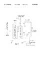
- FIG. 1is a schematic illustration of an ultrasound phased array system according to the prior art where each transducer element is driven by its own designated amplifier and matching network;
- FIG. 2is a schematic illustration of the ultrasound phased array system of the present invention with its reduced number of amplifiers
- FIG. 3is a schematic diagram similar to FIG. 2, of a second embodiment of the present ultrasound phased array system
- FIG. 4is a schematic illustration of an ultrasound phased array system according to another embodiment of the present invention.
- FIG. 5is a schematic illustration of one implementation of an MUX chip as utilized in the embodiment of FIG. 4.
- Prior system 10included a number of ultrasonic transducer elements 12, up to a thousand or more, and a corresponding number of drive amplifiers 14. Each drive amplifier is coupled to one specific transducer element 12. The amplifiers 14 produce square wave drive signals 16 that drive the transducer elements 12. Each amplifier 14 also includes its own matching network 18 which partially filters the drive signal 16 received from the amplifier 14 on the drive line 20 and provides the drive signal to the transducer element 12 on line 22. As readily seen by this figure, the number of amplifiers 16 and matching networks 18 directly corresponds to the number of transducer elements 12. For a large aperture array, which may have over a thousand transducer elements 12, it is easily seen that the overall cost, size and portability of the system 10 is compromised as the array size increases.
- FIG. 2An overall system configuration for an ultrasound phased array system 30 according to one embodiment of the present invention is shown in FIG. 2.
- the phase of any particular transducer element 32is determined by an n-bit binary code resulting in only 2 n possible phases at which the transducer element 32 can be driven.
- the array 31itself is made up of a number of transducer elements 32 which are greater than the number of possible phases.
- the present inventionincludes means for specifying and implementing the proper connection between each transducer element 32 and the smaller number of driving signals. This is achieved by the incorporation of integrated multiplexer circuit (MUX) chips 34 into the system 30 design.
- MUXintegrated multiplexer circuit
- one MUX chip 34is coupled to each transducer element 32 by line 36 and each MUX chip 34 is coupled to all of the amplifiers 38 by lines 39.
- a serial or parallel digital data bus 40connects a controller 50, by lines 42, to each MUX chip 34.
- Data provided by the controller 50 to the MUX chips 34includes an n-bit binary code which specifies the drive line 39 or amplifier 38 to which each transducer element 32 is to be connected.
- FIG. 3An alternative embodiment of an ultrasound phased array system 30' according to the present invention is schematically illustrated in FIG. 3. Since the embodiment of FIG. 3 has numerous components in common with the embodiment of FIG. 2, like components are being designated with like item numbers.
- This second embodimentdiffers from the first embodiment in that the second embodiment is equipped to utilize at least some of the transducer elements 32 as receivers, thereby allowing for the measuring of "phase delays" between the transmitting transducer elements 32 and a treatment volume into which the acoustic beam is being formed or focused.
- a beacon transducer(not shown), positioned within the treatment volume by a catheter, needle or other appropriate mechanism, transmits a sinusoidal signal (CW or tone burst).
- This signalis received in parallel by all the transducer elements 32 which are specified by the data bus 40 as being receiver elements 32.
- the time required for beam reformingis reduced by a factor corresponding to the number of phases being measured.
- Such a reduction in beam reforming timeis extremely important where beam reformation is used to allow the beam to track and follow a moving target, such as a target cardiac tissue volume during cardiac ablation.
- the drive line 39 to which a particular transducer element 32 is connectedBy simply changing, via the MUX chip 34, the drive line 39 to which a particular transducer element 32 is connected, adaptive beam forming is effectuated.
- the small digital control lines 42 to the MUX chips 34are easily shielded from system operating electrical noise and no loading or operating of specialized memory chips is required. Only the controller's generation of the appropriate digital code, to specify which MUX chip 34 connects its transducer element 32 to which drive line 39, is required.
- Transistor switches 44FET switches
- Line 45couples the controller 50 to the transistor switches 44 and is utilized as an "on/off" control line.
- Similar transistor switchescan be used to remove the output of the drive amplifiers 38 from the lines 36 being used as receiver lines for the various transducer elements 32 being used as receivers. In this way, the system 30' is provided with maximum sensitivity.
- Phase data from the receiver transducer elements 32 and the phase measurement circuitry 46is transferred via lines 48 to the controller 50. Based on the phase data, the controller 50 recalculates the focus of the beam to maintain the beam specifically on the target tissue volume.
- the controller 50is PC based or may be any other well known type of controller. During operation of the system 30', the controller 50 specifies over the data bus 40 which specific transducer element, and therefore which specific MUX chip 34, are to receive the drive signal from a specific amplifier 38.
- the driving signals themselves(which may be sinusoidal, square wave or other) are provided to the MUX chips 34 by a drive line bus 52.
- the controller 50also provides the appropriate signals to the MUX chips 34 whose transducer elements 32 are to be used as receiver elements and provides appropriate control signals via line 54 to the drive amplifiers 38 specifically their operational phase.
- the drive amplifiers 38are preferably of a low output impedance design (voltage sources) where the drive voltage remains constant as the impedance changes. Impedance changes will occur as a result of changing connections by the MUX chips 34 to different sets of transducer elements 32 as the acoustic beam is refocused during a procedure.
- the design of the amplifiers 38can be such that their output impedance is matched to the expected local impedance. This reduces reflection and possible standing wave problems if the drive lines 39 are long.
- the drive amplitudecould be controlled on a per amplifier/transducer basis providing good flexibility for amplitude and phase control.
- the amplitudesare all the same unless special design features are incorporated into the systems 30 and 30'.
- phased arraysare typically used in either a full "on” or a full “off” amplitude control mode.
- one of the drive lines 39is sacrificed as an "on/off” line and therefore carries no drive signal. This leaves 2 n -1 discrete phases for beam forming.
- the transducer element 32is connected to the sacrificed drive line 39.
- phase at which any particular transducer element 32 is drivenis determined by a n-bit binary code and this results in possible phases, which in this embodiment are provided as low level digital phase signals.
- the array 31 formed by the elements 32is caused to produce a focused ultrasonic beam.
- MUX chipsintegrated circuit multiplexers
- the MUX chips 56each include two multiplexers thereon. As seen in FIG. 5, one is the phase line connect multiplexer 58 (or phase generation circuit) and the other is the driver circuit multiplexer 60.
- phase line connect multiplexer 58 of each MUX chip 56is connected with the 2 n phase lines 62 which are in turn coupled through the phase line bus 64 to the low level digital phase signal generator 66.
- the phase signal generator 66itself is controlled by the controller 50 or other approximate means by way of line 67. Switching within each MUX chip 56 between the phase signals provided over the phase lines 62 is controlled by the switch driver circuit multiplexer 60.
- the phase line connect multiplexers 58 and the switch driver circuit multiplexers 60receive their signals from the controller 50 through a data bus 68 (which may be either a serial data bus or a parallel data bus) and over lines 70.
- the data provided from the data bus 68includes the n-bit binary code which specifies the phase line 62 to which the phase line connect multiplexer 58 will connect.
- the dataalso includes a k-bit binary code which specifies the element 32 to which the switch driver circuit multiplexer 60 will connect.
- the phase signalis generated internally of the MUX chips 56.
- one clock line(alternately designated as 72) enters each MUX chip 56.
- the n-bit binary codewould then designate which phase is to be generated by a phase generation circuit (alternately designated at 74 in FIG. 5).
- Advantages of generating the phase signals on the MUX chips 56include a reduction in the number of signal lines from the controller 50 and an ability to specify the amplitude of each channel separately. The latter advantage would be accomplished via a digital code at the controller 50 which would specify the duty cycle of the phase signal and therefore the amplitude of the phase signal to the element 32.
- Two additional switches 76 and 78are provided on the MUX chips 56 and connected to the switch driver circuit multiplexer 60.
- One of these switches 78is connected to a high voltage supply 80 and the other to ground 82.
- the switch 78 connected to ground 82is further connected in parallel with a receiver switch 84 also on the MUX chip 56.
- an external, auxiliary receiver multiplexer 88is connected to the output lines 90 of the receiver switches 84 while also being connected to the controller 50 by way of a receive on/off control line 92.
- the output lines 90 of the receiver switches 84are more specifically connected to transistor (FET) switches 91 of the auxiliary receiver multiplexer 88, which in turn terminate via lines 97 at phase measurement circuitry 96 of a well known construction.
- the on/off control line 92 from the controller 50is used to open and close the transistor switches 91 permitting, in conjunction with the receive enable line 94, a number or subset of the elements 32 to operate as receiver elements.
- a transmitter transducer(not shown) is positioned by a catheter, needle or other means in the treatment volume and the transmitter transducer is caused to transmit a sinusoidal (CW or tone burst) signal.
- the controller 50activates an appropriate number of elements 32 to operate as receivers by closing the appropriate receiver switches 84 via the receiver enable lines 94 and closing the corresponding FET switches 91 via the on/off control line 92.
- the receiver switches 84By utilizing the receiver switches 84, one of several elements 32 is connected to an output line 90 allowing a number of output lines 90 to monitor a subset of the elements 32 as receivers.
- the phase measurement circuitry 96provides the phase measurements to the controller 50. With the output lines 90 and lines 97 providing the received phase signals in parallel to the phase measurement circuitry 96, the measurement process and refocusing or reformation of the beam is reduced by a factor of q (the number of elements 32 operating as receivers). This is essential if a rapidly moving target is to be tracked, such as during cardiac ablation.
- the FET and receiver switches 91, 84serve another purpose. By remaining open during beam formation, the FET and receiver switches 91, 84 protect the phase measurement circuitry 96 from the higher voltage output to the elements 32.
- Each MUX chip 34, 56is preferably surface mounted on an interconnect board consisting of a set of multi-layer circuit boards or multi-layer flex boards located very close to the transducer elements 32. This design is advantageous in that it saves space and eliminates long unshielded lines 36 from the MUX chips 34, 56 to the transducer elements 32.
- the MUX chips 34, 56can be surface mounted on flex board (not shown) directly above the back surface of the array 31 within the housing 35 of the array structure. This is illustrated in FIG. 2.
- the MUX chips 34, 56can be mounted directly on the back surface of an array 31 where circuit board-like interconnectors are formed on the back surface of the polymer matrix which forms the substrate 33 or bulk of the composite array 31. This is illustrated in FIG. 3.
Landscapes
- Physics & Mathematics (AREA)
- Engineering & Computer Science (AREA)
- Acoustics & Sound (AREA)
- Multimedia (AREA)
- Ultra Sonic Daignosis Equipment (AREA)
- Investigating Or Analyzing Materials By The Use Of Ultrasonic Waves (AREA)
- Measurement Of Velocity Or Position Using Acoustic Or Ultrasonic Waves (AREA)
Abstract
Description
Claims (32)
Priority Applications (5)
| Application Number | Priority Date | Filing Date | Title |
|---|---|---|---|
| US08/927,599US6128958A (en) | 1997-09-11 | 1997-09-11 | Phased array system architecture |
| AU92219/98AAU9221998A (en) | 1997-09-11 | 1998-09-04 | Phased array system architecture |
| JP2000511149AJP2001516075A (en) | 1997-09-11 | 1998-09-04 | Ultrasonic phased array drive system and focused ultrasonic beam generation and directing system |
| PCT/US1998/018514WO1999013452A2 (en) | 1997-09-11 | 1998-09-04 | Phased array system architecture |
| EP98944757AEP1051699A2 (en) | 1997-09-11 | 1998-09-04 | Phased array system architecture |
Applications Claiming Priority (1)
| Application Number | Priority Date | Filing Date | Title |
|---|---|---|---|
| US08/927,599US6128958A (en) | 1997-09-11 | 1997-09-11 | Phased array system architecture |
Publications (1)
| Publication Number | Publication Date |
|---|---|
| US6128958Atrue US6128958A (en) | 2000-10-10 |
Family
ID=25454969
Family Applications (1)
| Application Number | Title | Priority Date | Filing Date |
|---|---|---|---|
| US08/927,599Expired - Fee RelatedUS6128958A (en) | 1997-09-11 | 1997-09-11 | Phased array system architecture |
Country Status (5)
| Country | Link |
|---|---|
| US (1) | US6128958A (en) |
| EP (1) | EP1051699A2 (en) |
| JP (1) | JP2001516075A (en) |
| AU (1) | AU9221998A (en) |
| WO (1) | WO1999013452A2 (en) |
Cited By (80)
| Publication number | Priority date | Publication date | Assignee | Title |
|---|---|---|---|---|
| US6246898B1 (en)* | 1995-03-28 | 2001-06-12 | Sonometrics Corporation | Method for carrying out a medical procedure using a three-dimensional tracking and imaging system |
| US6506154B1 (en)* | 2000-11-28 | 2003-01-14 | Insightec-Txsonics, Ltd. | Systems and methods for controlling a phased array focused ultrasound system |
| US6561979B1 (en)* | 1999-09-14 | 2003-05-13 | Acuson Corporation | Medical diagnostic ultrasound system and method |
| US6676602B1 (en)* | 2002-07-25 | 2004-01-13 | Siemens Medical Solutions Usa, Inc. | Two dimensional array switching for beamforming in a volume |
| US20040162507A1 (en)* | 2003-02-19 | 2004-08-19 | Assaf Govari | Externally-applied high intensity focused ultrasound (HIFU) for therapeutic treatment |
| US20040236253A1 (en)* | 2003-05-22 | 2004-11-25 | Insightec-Image Guided Treatment Ltd. | Acoustic beam forming in phased arrays including large numbers of transducer elements |
| US20050243812A1 (en)* | 2004-04-28 | 2005-11-03 | Siemens Medical So.Utions Usa, Inc. | Dynamic sub-array mapping systems and methods for ultrasound imaging |
| US20070055179A1 (en)* | 2005-09-07 | 2007-03-08 | Deem Mark E | Method for treating subcutaneous tissues |
| US20070083120A1 (en)* | 2005-09-22 | 2007-04-12 | Cain Charles A | Pulsed cavitational ultrasound therapy |
| US20070239001A1 (en)* | 2005-11-02 | 2007-10-11 | James Mehi | High frequency array ultrasound system |
| US20080014627A1 (en)* | 2005-12-02 | 2008-01-17 | Cabochon Aesthetics, Inc. | Devices and methods for selectively lysing cells |
| WO2007085892A3 (en)* | 2005-11-23 | 2008-05-08 | Insightec Ltd | Hierarchical switching in ultra-high density ultrasound array |
| US20080195036A1 (en)* | 2005-12-02 | 2008-08-14 | Cabochon Aesthetics, Inc. | Devices and methods for selectively lysing cells |
| US20080200864A1 (en)* | 2005-12-02 | 2008-08-21 | Cabochon Aesthetics, Inc. | Devices and methods for selectively lysing cells |
| US20080197517A1 (en)* | 2005-12-02 | 2008-08-21 | Cabochon Aesthetics, Inc. | Devices and methods for selectively lysing cells |
| US20080200863A1 (en)* | 2005-12-02 | 2008-08-21 | Cabochon Aesthetics, Inc. | Devices and methods for selectively lysing cells |
| US20080230987A1 (en)* | 2007-03-20 | 2008-09-25 | Jackson Perry L | Gaming control holder |
| US20080248554A1 (en)* | 2005-12-02 | 2008-10-09 | Cabochon Aesthetics, Inc. | Devices and methods for selectively lysing cells |
| US20090177085A1 (en)* | 2005-09-22 | 2009-07-09 | Adam Maxwell | Histotripsy for thrombolysis |
| US7587291B1 (en) | 2008-05-05 | 2009-09-08 | Artann Laboratories | Focusing of broadband acoustic signals using time-reversed acoustics |
| US7806892B2 (en) | 2001-05-29 | 2010-10-05 | Ethicon Endo-Surgery, Inc. | Tissue-retaining system for ultrasound medical treatment |
| US7806839B2 (en)* | 2004-06-14 | 2010-10-05 | Ethicon Endo-Surgery, Inc. | System and method for ultrasound therapy using grating lobes |
| US7830069B2 (en) | 2004-04-20 | 2010-11-09 | Sunnybrook Health Sciences Centre | Arrayed ultrasonic transducer |
| US7846096B2 (en) | 2001-05-29 | 2010-12-07 | Ethicon Endo-Surgery, Inc. | Method for monitoring of medical treatment using pulse-echo ultrasound |
| US20110074630A1 (en)* | 2009-09-30 | 2011-03-31 | Snow Jeffrey M | Aperiodic Antenna Array |
| US20110074646A1 (en)* | 2009-09-30 | 2011-03-31 | Snow Jeffrey M | Antenna array |
| US8057408B2 (en) | 2005-09-22 | 2011-11-15 | The Regents Of The University Of Michigan | Pulsed cavitational ultrasound therapy |
| US8088067B2 (en) | 2002-12-23 | 2012-01-03 | Insightec Ltd. | Tissue aberration corrections in ultrasound therapy |
| US8235901B2 (en) | 2006-04-26 | 2012-08-07 | Insightec, Ltd. | Focused ultrasound system with far field tail suppression |
| US8251908B2 (en) | 2007-10-01 | 2012-08-28 | Insightec Ltd. | Motion compensated image-guided focused ultrasound therapy system |
| US8316518B2 (en) | 2008-09-18 | 2012-11-27 | Visualsonics Inc. | Methods for manufacturing ultrasound transducers and other components |
| USRE43901E1 (en) | 2000-11-28 | 2013-01-01 | Insightec Ltd. | Apparatus for controlling thermal dosing in a thermal treatment system |
| US8368401B2 (en) | 2009-11-10 | 2013-02-05 | Insightec Ltd. | Techniques for correcting measurement artifacts in magnetic resonance thermometry |
| US8409099B2 (en) | 2004-08-26 | 2013-04-02 | Insightec Ltd. | Focused ultrasound system for surrounding a body tissue mass and treatment method |
| US8425424B2 (en) | 2008-11-19 | 2013-04-23 | Inightee Ltd. | Closed-loop clot lysis |
| US8539813B2 (en) | 2009-09-22 | 2013-09-24 | The Regents Of The University Of Michigan | Gel phantoms for testing cavitational ultrasound (histotripsy) transducers |
| WO2013188817A1 (en)* | 2012-06-15 | 2013-12-19 | University Of Southern California | Ultrasound beamformer with individual array element multiplexers |
| US8617073B2 (en) | 2009-04-17 | 2013-12-31 | Insightec Ltd. | Focusing ultrasound into the brain through the skull by utilizing both longitudinal and shear waves |
| US8661873B2 (en) | 2009-10-14 | 2014-03-04 | Insightec Ltd. | Mapping ultrasound transducers |
| US8894678B2 (en) | 2009-08-07 | 2014-11-25 | Ulthera, Inc. | Cellulite treatment methods |
| US8932237B2 (en) | 2010-04-28 | 2015-01-13 | Insightec, Ltd. | Efficient ultrasound focusing |
| US9011473B2 (en) | 2005-09-07 | 2015-04-21 | Ulthera, Inc. | Dissection handpiece and method for reducing the appearance of cellulite |
| US9033889B2 (en)* | 2012-01-11 | 2015-05-19 | Angiodynamics, Inc. | Methods, assemblies, and devices for positioning a catheter tip using an ultrasonic imaging system |
| US9039722B2 (en) | 2007-10-09 | 2015-05-26 | Ulthera, Inc. | Dissection handpiece with aspiration means for reducing the appearance of cellulite |
| US9049783B2 (en) | 2012-04-13 | 2015-06-02 | Histosonics, Inc. | Systems and methods for obtaining large creepage isolation on printed circuit boards |
| US9061131B2 (en) | 2009-08-17 | 2015-06-23 | Histosonics, Inc. | Disposable acoustic coupling medium container |
| US9144694B2 (en) | 2011-08-10 | 2015-09-29 | The Regents Of The University Of Michigan | Lesion generation through bone using histotripsy therapy without aberration correction |
| US9173047B2 (en) | 2008-09-18 | 2015-10-27 | Fujifilm Sonosite, Inc. | Methods for manufacturing ultrasound transducers and other components |
| US9177543B2 (en) | 2009-08-26 | 2015-11-03 | Insightec Ltd. | Asymmetric ultrasound phased-array transducer for dynamic beam steering to ablate tissues in MRI |
| US9184369B2 (en) | 2008-09-18 | 2015-11-10 | Fujifilm Sonosite, Inc. | Methods for manufacturing ultrasound transducers and other components |
| US9272124B2 (en) | 2005-12-02 | 2016-03-01 | Ulthera, Inc. | Systems and devices for selective cell lysis and methods of using same |
| US9289154B2 (en) | 2009-08-19 | 2016-03-22 | Insightec Ltd. | Techniques for temperature measurement and corrections in long-term magnetic resonance thermometry |
| US9358033B2 (en) | 2005-09-07 | 2016-06-07 | Ulthera, Inc. | Fluid-jet dissection system and method for reducing the appearance of cellulite |
| US9358064B2 (en) | 2009-08-07 | 2016-06-07 | Ulthera, Inc. | Handpiece and methods for performing subcutaneous surgery |
| US9623266B2 (en) | 2009-08-04 | 2017-04-18 | Insightec Ltd. | Estimation of alignment parameters in magnetic-resonance-guided ultrasound focusing |
| US9636133B2 (en) | 2012-04-30 | 2017-05-02 | The Regents Of The University Of Michigan | Method of manufacturing an ultrasound system |
| US9852727B2 (en) | 2010-04-28 | 2017-12-26 | Insightec, Ltd. | Multi-segment ultrasound transducers |
| US9901753B2 (en) | 2009-08-26 | 2018-02-27 | The Regents Of The University Of Michigan | Ultrasound lithotripsy and histotripsy for using controlled bubble cloud cavitation in fractionating urinary stones |
| US9943708B2 (en) | 2009-08-26 | 2018-04-17 | Histosonics, Inc. | Automated control of micromanipulator arm for histotripsy prostate therapy while imaging via ultrasound transducers in real time |
| US9981148B2 (en) | 2010-10-22 | 2018-05-29 | Insightec, Ltd. | Adaptive active cooling during focused ultrasound treatment |
| US10130828B2 (en) | 2005-06-21 | 2018-11-20 | Insightec Ltd. | Controlled, non-linear focused ultrasound treatment |
| US10188831B2 (en) | 2013-03-14 | 2019-01-29 | Angiodynamics, Inc. | Systems and methods for catheter tip placement using ECG |
| US10293187B2 (en) | 2013-07-03 | 2019-05-21 | Histosonics, Inc. | Histotripsy excitation sequences optimized for bubble cloud formation using shock scattering |
| US10531888B2 (en) | 2009-08-07 | 2020-01-14 | Ulthera, Inc. | Methods for efficiently reducing the appearance of cellulite |
| US10548659B2 (en) | 2006-01-17 | 2020-02-04 | Ulthera, Inc. | High pressure pre-burst for improved fluid delivery |
| US10780298B2 (en) | 2013-08-22 | 2020-09-22 | The Regents Of The University Of Michigan | Histotripsy using very short monopolar ultrasound pulses |
| US11058399B2 (en) | 2012-10-05 | 2021-07-13 | The Regents Of The University Of Michigan | Bubble-induced color doppler feedback during histotripsy |
| US11096708B2 (en) | 2009-08-07 | 2021-08-24 | Ulthera, Inc. | Devices and methods for performing subcutaneous surgery |
| US11135454B2 (en) | 2015-06-24 | 2021-10-05 | The Regents Of The University Of Michigan | Histotripsy therapy systems and methods for the treatment of brain tissue |
| US20220031287A1 (en)* | 2010-06-09 | 2022-02-03 | Regents Of The University Of Minnesota | Dual mode ultrasound transducer (dmut) system and method for controlling delivery of ultrasound therapy |
| US11432900B2 (en) | 2013-07-03 | 2022-09-06 | Histosonics, Inc. | Articulating arm limiter for cavitational ultrasound therapy system |
| US11607150B2 (en) | 2014-04-08 | 2023-03-21 | Angiodynamics Va Llc | Medical device placement system and a method for its use |
| US11648424B2 (en) | 2018-11-28 | 2023-05-16 | Histosonics Inc. | Histotripsy systems and methods |
| US11813485B2 (en) | 2020-01-28 | 2023-11-14 | The Regents Of The University Of Michigan | Systems and methods for histotripsy immunosensitization |
| US12179042B2 (en) | 2017-02-23 | 2024-12-31 | Oron Zachar | Transcranial ultrasound focusing |
| US12318636B2 (en) | 2022-10-28 | 2025-06-03 | Histosonics, Inc. | Histotripsy systems and methods |
| US12329991B2 (en) | 2018-04-06 | 2025-06-17 | Regents Of The University Of Minnesota | Wearable transcranial dual-mode ultrasound transducers for neuromodulation |
| US12343568B2 (en) | 2020-08-27 | 2025-07-01 | The Regents Of The University Of Michigan | Ultrasound transducer with transmit-receive capability for histotripsy |
| US12390190B2 (en) | 2016-04-19 | 2025-08-19 | Koninklijke Philips N.V. | Acoustic registration of internal and external ultrasound probes |
| US12402802B2 (en) | 2011-08-31 | 2025-09-02 | Insightec Ltd. | Avoiding MRI-interference with co-existing systems |
Families Citing this family (1)
| Publication number | Priority date | Publication date | Assignee | Title |
|---|---|---|---|---|
| CN113730832B (en)* | 2021-09-08 | 2024-03-08 | 中惠医疗科技(上海)有限公司 | Phase-control focusing multichannel ultrasonic driving circuit and multichannel ultrasonic therapeutic apparatus |
Citations (27)
| Publication number | Priority date | Publication date | Assignee | Title |
|---|---|---|---|---|
| US4117446A (en)* | 1974-11-28 | 1978-09-26 | Agence Nationale De Valorisation De La Recherche (A N V A R) | Devices for probing by ultrasonic radiation |
| EP0017382A1 (en)* | 1979-03-20 | 1980-10-15 | THE GENERAL ELECTRIC COMPANY, p.l.c. | Ultrasonic imaging system |
| US4351038A (en)* | 1979-12-31 | 1982-09-21 | Agence Nationale De Valorisation De La Recherche (Anvar) | Ultrasonic examination and imaging |
| GB2099582A (en)* | 1980-02-08 | 1982-12-08 | Stanford Res Inst Int | Ultrasonic image methods and apparatus |
| US4549533A (en)* | 1984-01-30 | 1985-10-29 | University Of Illinois | Apparatus and method for generating and directing ultrasound |
| US4550606A (en)* | 1982-09-28 | 1985-11-05 | Cornell Research Foundation, Inc. | Ultrasonic transducer array with controlled excitation pattern |
| US4622972A (en)* | 1981-10-05 | 1986-11-18 | Varian Associates, Inc. | Ultrasound hyperthermia applicator with variable coherence by multi-spiral focusing |
| US4757820A (en)* | 1985-03-15 | 1988-07-19 | Kabushiki Kaisha Toshiba | Ultrasound therapy system |
| US4791915A (en)* | 1986-09-29 | 1988-12-20 | Dynawave Corporation | Ultrasound therapy device |
| US4829491A (en)* | 1984-07-12 | 1989-05-09 | Siemens Aktiengesellschaft | Phased-array equipment |
| EP0320303A2 (en)* | 1987-12-11 | 1989-06-14 | General Electric Company | Coherent beam formation |
| US4888746A (en)* | 1987-09-24 | 1989-12-19 | Richard Wolf Gmbh | Focussing ultrasound transducer |
| US4890267A (en)* | 1985-09-24 | 1989-12-26 | Hewlett-Packard Company | Switch matrix |
| US4938217A (en)* | 1988-06-21 | 1990-07-03 | Massachusetts Institute Of Technology | Electronically-controlled variable focus ultrasound hyperthermia system |
| US5091893A (en)* | 1990-04-05 | 1992-02-25 | General Electric Company | Ultrasonic array with a high density of electrical connections |
| US5092336A (en)* | 1989-02-08 | 1992-03-03 | Universite Paris Vii-Bureau De La Valorisation Et De Relations Industrielle | Method and device for localization and focusing of acoustic waves in tissues |
| US5097709A (en)* | 1989-02-16 | 1992-03-24 | Hitachi, Ltd. | Ultrasonic imaging system |
| US5158071A (en)* | 1988-07-01 | 1992-10-27 | Hitachi, Ltd. | Ultrasonic apparatus for therapeutical use |
| US5295484A (en)* | 1992-05-19 | 1994-03-22 | Arizona Board Of Regents For And On Behalf Of The University Of Arizona | Apparatus and method for intra-cardiac ablation of arrhythmias |
| US5316000A (en)* | 1991-03-05 | 1994-05-31 | Technomed International (Societe Anonyme) | Use of at least one composite piezoelectric transducer in the manufacture of an ultrasonic therapy apparatus for applying therapy, in a body zone, in particular to concretions, to tissue, or to bones, of a living being and method of ultrasonic therapy |
| US5501655A (en)* | 1992-03-31 | 1996-03-26 | Massachusetts Institute Of Technology | Apparatus and method for acoustic heat generation and hyperthermia |
| US5563346A (en)* | 1994-02-21 | 1996-10-08 | Siemens Aktiengesellschaft | Method and device for imaging an object using a two-dimensional ultrasonic array |
| US5566675A (en)* | 1995-06-30 | 1996-10-22 | Siemens Medical Systems, Inc. | Beamformer for phase aberration correction |
| US5617862A (en)* | 1995-05-02 | 1997-04-08 | Acuson Corporation | Method and apparatus for beamformer system with variable aperture |
| US5769790A (en)* | 1996-10-25 | 1998-06-23 | General Electric Company | Focused ultrasound surgery system guided by ultrasound imaging |
| US5797848A (en)* | 1997-01-31 | 1998-08-25 | Acuson Corporation | Ultrasonic transducer assembly with improved electrical interface |
| US5932807A (en)* | 1994-10-25 | 1999-08-03 | U.S. Philips Corporation | Device for the non-destructive testing of hollow tubular objects by means of ultrasound |
Family Cites Families (2)
| Publication number | Priority date | Publication date | Assignee | Title |
|---|---|---|---|---|
| US5357962A (en)* | 1992-01-27 | 1994-10-25 | Sri International | Ultrasonic imaging system and method wtih focusing correction |
| US5797849A (en)* | 1995-03-28 | 1998-08-25 | Sonometrics Corporation | Method for carrying out a medical procedure using a three-dimensional tracking and imaging system |
- 1997
- 1997-09-11USUS08/927,599patent/US6128958A/ennot_activeExpired - Fee Related
- 1998
- 1998-09-04JPJP2000511149Apatent/JP2001516075A/enactivePending
- 1998-09-04WOPCT/US1998/018514patent/WO1999013452A2/ennot_activeApplication Discontinuation
- 1998-09-04EPEP98944757Apatent/EP1051699A2/ennot_activeWithdrawn
- 1998-09-04AUAU92219/98Apatent/AU9221998A/ennot_activeAbandoned
Patent Citations (27)
| Publication number | Priority date | Publication date | Assignee | Title |
|---|---|---|---|---|
| US4117446A (en)* | 1974-11-28 | 1978-09-26 | Agence Nationale De Valorisation De La Recherche (A N V A R) | Devices for probing by ultrasonic radiation |
| EP0017382A1 (en)* | 1979-03-20 | 1980-10-15 | THE GENERAL ELECTRIC COMPANY, p.l.c. | Ultrasonic imaging system |
| US4351038A (en)* | 1979-12-31 | 1982-09-21 | Agence Nationale De Valorisation De La Recherche (Anvar) | Ultrasonic examination and imaging |
| GB2099582A (en)* | 1980-02-08 | 1982-12-08 | Stanford Res Inst Int | Ultrasonic image methods and apparatus |
| US4622972A (en)* | 1981-10-05 | 1986-11-18 | Varian Associates, Inc. | Ultrasound hyperthermia applicator with variable coherence by multi-spiral focusing |
| US4550606A (en)* | 1982-09-28 | 1985-11-05 | Cornell Research Foundation, Inc. | Ultrasonic transducer array with controlled excitation pattern |
| US4549533A (en)* | 1984-01-30 | 1985-10-29 | University Of Illinois | Apparatus and method for generating and directing ultrasound |
| US4829491A (en)* | 1984-07-12 | 1989-05-09 | Siemens Aktiengesellschaft | Phased-array equipment |
| US4757820A (en)* | 1985-03-15 | 1988-07-19 | Kabushiki Kaisha Toshiba | Ultrasound therapy system |
| US4890267A (en)* | 1985-09-24 | 1989-12-26 | Hewlett-Packard Company | Switch matrix |
| US4791915A (en)* | 1986-09-29 | 1988-12-20 | Dynawave Corporation | Ultrasound therapy device |
| US4888746A (en)* | 1987-09-24 | 1989-12-19 | Richard Wolf Gmbh | Focussing ultrasound transducer |
| EP0320303A2 (en)* | 1987-12-11 | 1989-06-14 | General Electric Company | Coherent beam formation |
| US4938217A (en)* | 1988-06-21 | 1990-07-03 | Massachusetts Institute Of Technology | Electronically-controlled variable focus ultrasound hyperthermia system |
| US5158071A (en)* | 1988-07-01 | 1992-10-27 | Hitachi, Ltd. | Ultrasonic apparatus for therapeutical use |
| US5092336A (en)* | 1989-02-08 | 1992-03-03 | Universite Paris Vii-Bureau De La Valorisation Et De Relations Industrielle | Method and device for localization and focusing of acoustic waves in tissues |
| US5097709A (en)* | 1989-02-16 | 1992-03-24 | Hitachi, Ltd. | Ultrasonic imaging system |
| US5091893A (en)* | 1990-04-05 | 1992-02-25 | General Electric Company | Ultrasonic array with a high density of electrical connections |
| US5316000A (en)* | 1991-03-05 | 1994-05-31 | Technomed International (Societe Anonyme) | Use of at least one composite piezoelectric transducer in the manufacture of an ultrasonic therapy apparatus for applying therapy, in a body zone, in particular to concretions, to tissue, or to bones, of a living being and method of ultrasonic therapy |
| US5501655A (en)* | 1992-03-31 | 1996-03-26 | Massachusetts Institute Of Technology | Apparatus and method for acoustic heat generation and hyperthermia |
| US5295484A (en)* | 1992-05-19 | 1994-03-22 | Arizona Board Of Regents For And On Behalf Of The University Of Arizona | Apparatus and method for intra-cardiac ablation of arrhythmias |
| US5563346A (en)* | 1994-02-21 | 1996-10-08 | Siemens Aktiengesellschaft | Method and device for imaging an object using a two-dimensional ultrasonic array |
| US5932807A (en)* | 1994-10-25 | 1999-08-03 | U.S. Philips Corporation | Device for the non-destructive testing of hollow tubular objects by means of ultrasound |
| US5617862A (en)* | 1995-05-02 | 1997-04-08 | Acuson Corporation | Method and apparatus for beamformer system with variable aperture |
| US5566675A (en)* | 1995-06-30 | 1996-10-22 | Siemens Medical Systems, Inc. | Beamformer for phase aberration correction |
| US5769790A (en)* | 1996-10-25 | 1998-06-23 | General Electric Company | Focused ultrasound surgery system guided by ultrasound imaging |
| US5797848A (en)* | 1997-01-31 | 1998-08-25 | Acuson Corporation | Ultrasonic transducer assembly with improved electrical interface |
Cited By (139)
| Publication number | Priority date | Publication date | Assignee | Title |
|---|---|---|---|---|
| US6246898B1 (en)* | 1995-03-28 | 2001-06-12 | Sonometrics Corporation | Method for carrying out a medical procedure using a three-dimensional tracking and imaging system |
| US6561979B1 (en)* | 1999-09-14 | 2003-05-13 | Acuson Corporation | Medical diagnostic ultrasound system and method |
| USRE43901E1 (en) | 2000-11-28 | 2013-01-01 | Insightec Ltd. | Apparatus for controlling thermal dosing in a thermal treatment system |
| US6506154B1 (en)* | 2000-11-28 | 2003-01-14 | Insightec-Txsonics, Ltd. | Systems and methods for controlling a phased array focused ultrasound system |
| US7806892B2 (en) | 2001-05-29 | 2010-10-05 | Ethicon Endo-Surgery, Inc. | Tissue-retaining system for ultrasound medical treatment |
| US9005144B2 (en) | 2001-05-29 | 2015-04-14 | Michael H. Slayton | Tissue-retaining systems for ultrasound medical treatment |
| US9261596B2 (en) | 2001-05-29 | 2016-02-16 | T. Douglas Mast | Method for monitoring of medical treatment using pulse-echo ultrasound |
| US7846096B2 (en) | 2001-05-29 | 2010-12-07 | Ethicon Endo-Surgery, Inc. | Method for monitoring of medical treatment using pulse-echo ultrasound |
| US6676602B1 (en)* | 2002-07-25 | 2004-01-13 | Siemens Medical Solutions Usa, Inc. | Two dimensional array switching for beamforming in a volume |
| US8088067B2 (en) | 2002-12-23 | 2012-01-03 | Insightec Ltd. | Tissue aberration corrections in ultrasound therapy |
| US20040162507A1 (en)* | 2003-02-19 | 2004-08-19 | Assaf Govari | Externally-applied high intensity focused ultrasound (HIFU) for therapeutic treatment |
| US20040236253A1 (en)* | 2003-05-22 | 2004-11-25 | Insightec-Image Guided Treatment Ltd. | Acoustic beam forming in phased arrays including large numbers of transducer elements |
| US8002706B2 (en) | 2003-05-22 | 2011-08-23 | Insightec Ltd. | Acoustic beam forming in phased arrays including large numbers of transducer elements |
| US7611462B2 (en)* | 2003-05-22 | 2009-11-03 | Insightec-Image Guided Treatment Ltd. | Acoustic beam forming in phased arrays including large numbers of transducer elements |
| US7830069B2 (en) | 2004-04-20 | 2010-11-09 | Sunnybrook Health Sciences Centre | Arrayed ultrasonic transducer |
| US20050243812A1 (en)* | 2004-04-28 | 2005-11-03 | Siemens Medical So.Utions Usa, Inc. | Dynamic sub-array mapping systems and methods for ultrasound imaging |
| US7635334B2 (en)* | 2004-04-28 | 2009-12-22 | Siemens Medical Solutions Usa, Inc. | Dynamic sub-array mapping systems and methods for ultrasound imaging |
| US9132287B2 (en) | 2004-06-14 | 2015-09-15 | T. Douglas Mast | System and method for ultrasound treatment using grating lobes |
| US7806839B2 (en)* | 2004-06-14 | 2010-10-05 | Ethicon Endo-Surgery, Inc. | System and method for ultrasound therapy using grating lobes |
| US8409099B2 (en) | 2004-08-26 | 2013-04-02 | Insightec Ltd. | Focused ultrasound system for surrounding a body tissue mass and treatment method |
| US10130828B2 (en) | 2005-06-21 | 2018-11-20 | Insightec Ltd. | Controlled, non-linear focused ultrasound treatment |
| US9364246B2 (en) | 2005-09-07 | 2016-06-14 | Ulthera, Inc. | Dissection handpiece and method for reducing the appearance of cellulite |
| US7601128B2 (en) | 2005-09-07 | 2009-10-13 | Cabochon Aesthetics, Inc. | Apparatus for treating subcutaneous tissues |
| US7588547B2 (en) | 2005-09-07 | 2009-09-15 | Cabochon Aesthetics, Inc. | Methods and system for treating subcutaneous tissues |
| US9011473B2 (en) | 2005-09-07 | 2015-04-21 | Ulthera, Inc. | Dissection handpiece and method for reducing the appearance of cellulite |
| US9005229B2 (en) | 2005-09-07 | 2015-04-14 | Ulthera, Inc. | Dissection handpiece and method for reducing the appearance of cellulite |
| US7967763B2 (en) | 2005-09-07 | 2011-06-28 | Cabochon Aesthetics, Inc. | Method for treating subcutaneous tissues |
| US9358033B2 (en) | 2005-09-07 | 2016-06-07 | Ulthera, Inc. | Fluid-jet dissection system and method for reducing the appearance of cellulite |
| US9179928B2 (en) | 2005-09-07 | 2015-11-10 | Ulthera, Inc. | Dissection handpiece and method for reducing the appearance of cellulite |
| US20070055179A1 (en)* | 2005-09-07 | 2007-03-08 | Deem Mark E | Method for treating subcutaneous tissues |
| US8057408B2 (en) | 2005-09-22 | 2011-11-15 | The Regents Of The University Of Michigan | Pulsed cavitational ultrasound therapy |
| US10219815B2 (en) | 2005-09-22 | 2019-03-05 | The Regents Of The University Of Michigan | Histotripsy for thrombolysis |
| US12303152B2 (en) | 2005-09-22 | 2025-05-20 | The Regents Of The University Of Michigan | Histotripsy for thrombolysis |
| US11701134B2 (en) | 2005-09-22 | 2023-07-18 | The Regents Of The University Of Michigan | Histotripsy for thrombolysis |
| US12150661B2 (en) | 2005-09-22 | 2024-11-26 | The Regents Of The University Of Michigan | Histotripsy for thrombolysis |
| US11364042B2 (en) | 2005-09-22 | 2022-06-21 | The Regents Of The University Of Michigan | Histotripsy for thrombolysis |
| US20090177085A1 (en)* | 2005-09-22 | 2009-07-09 | Adam Maxwell | Histotripsy for thrombolysis |
| US9642634B2 (en) | 2005-09-22 | 2017-05-09 | The Regents Of The University Of Michigan | Pulsed cavitational ultrasound therapy |
| US20070083120A1 (en)* | 2005-09-22 | 2007-04-12 | Cain Charles A | Pulsed cavitational ultrasound therapy |
| US7901358B2 (en) | 2005-11-02 | 2011-03-08 | Visualsonics Inc. | High frequency array ultrasound system |
| US20070239001A1 (en)* | 2005-11-02 | 2007-10-11 | James Mehi | High frequency array ultrasound system |
| USRE46185E1 (en) | 2005-11-02 | 2016-10-25 | Fujifilm Sonosite, Inc. | High frequency array ultrasound system |
| WO2007085892A3 (en)* | 2005-11-23 | 2008-05-08 | Insightec Ltd | Hierarchical switching in ultra-high density ultrasound array |
| CN101313354B (en)* | 2005-11-23 | 2012-02-15 | 因赛泰克有限公司 | Hierarchical Switching in Ultra-High Density Ultrasound Arrays |
| US8608672B2 (en) | 2005-11-23 | 2013-12-17 | Insightec Ltd. | Hierarchical switching in ultra-high density ultrasound array |
| US20080248554A1 (en)* | 2005-12-02 | 2008-10-09 | Cabochon Aesthetics, Inc. | Devices and methods for selectively lysing cells |
| US20080200863A1 (en)* | 2005-12-02 | 2008-08-21 | Cabochon Aesthetics, Inc. | Devices and methods for selectively lysing cells |
| US9248317B2 (en) | 2005-12-02 | 2016-02-02 | Ulthera, Inc. | Devices and methods for selectively lysing cells |
| US20080014627A1 (en)* | 2005-12-02 | 2008-01-17 | Cabochon Aesthetics, Inc. | Devices and methods for selectively lysing cells |
| US9272124B2 (en) | 2005-12-02 | 2016-03-01 | Ulthera, Inc. | Systems and devices for selective cell lysis and methods of using same |
| US20080195036A1 (en)* | 2005-12-02 | 2008-08-14 | Cabochon Aesthetics, Inc. | Devices and methods for selectively lysing cells |
| US20080200864A1 (en)* | 2005-12-02 | 2008-08-21 | Cabochon Aesthetics, Inc. | Devices and methods for selectively lysing cells |
| US20080197517A1 (en)* | 2005-12-02 | 2008-08-21 | Cabochon Aesthetics, Inc. | Devices and methods for selectively lysing cells |
| US10548659B2 (en) | 2006-01-17 | 2020-02-04 | Ulthera, Inc. | High pressure pre-burst for improved fluid delivery |
| US8235901B2 (en) | 2006-04-26 | 2012-08-07 | Insightec, Ltd. | Focused ultrasound system with far field tail suppression |
| US20080230987A1 (en)* | 2007-03-20 | 2008-09-25 | Jackson Perry L | Gaming control holder |
| US8251908B2 (en) | 2007-10-01 | 2012-08-28 | Insightec Ltd. | Motion compensated image-guided focused ultrasound therapy system |
| US8548561B2 (en) | 2007-10-01 | 2013-10-01 | Insightec Ltd. | Motion compensated image-guided focused ultrasound therapy system |
| US9039722B2 (en) | 2007-10-09 | 2015-05-26 | Ulthera, Inc. | Dissection handpiece with aspiration means for reducing the appearance of cellulite |
| US10220122B2 (en) | 2007-10-09 | 2019-03-05 | Ulthera, Inc. | System for tissue dissection and aspiration |
| US7587291B1 (en) | 2008-05-05 | 2009-09-08 | Artann Laboratories | Focusing of broadband acoustic signals using time-reversed acoustics |
| US9555443B2 (en) | 2008-09-18 | 2017-01-31 | Fujifilm Sonosite, Inc. | Methods for manufacturing ultrasound transducers and other components |
| US12029131B2 (en) | 2008-09-18 | 2024-07-02 | Fujifilm Sonosite, Inc. | Methods for patterning electrodes of ultrasound transducers and other components |
| US9935254B2 (en) | 2008-09-18 | 2018-04-03 | Fujifilm Sonosite, Inc. | Methods for manufacturing ultrasound transducers and other components |
| US8316518B2 (en) | 2008-09-18 | 2012-11-27 | Visualsonics Inc. | Methods for manufacturing ultrasound transducers and other components |
| US11845108B2 (en) | 2008-09-18 | 2023-12-19 | Fujifilm Sonosite, Inc. | Methods for manufacturing ultrasound transducers and other components |
| US10596597B2 (en) | 2008-09-18 | 2020-03-24 | Fujifilm Sonosite, Inc. | Methods for manufacturing ultrasound transducers and other components |
| US9173047B2 (en) | 2008-09-18 | 2015-10-27 | Fujifilm Sonosite, Inc. | Methods for manufacturing ultrasound transducers and other components |
| US11094875B2 (en) | 2008-09-18 | 2021-08-17 | Fujifilm Sonosite, Inc. | Methods for manufacturing ultrasound transducers and other components |
| US9184369B2 (en) | 2008-09-18 | 2015-11-10 | Fujifilm Sonosite, Inc. | Methods for manufacturing ultrasound transducers and other components |
| US8425424B2 (en) | 2008-11-19 | 2013-04-23 | Inightee Ltd. | Closed-loop clot lysis |
| US8617073B2 (en) | 2009-04-17 | 2013-12-31 | Insightec Ltd. | Focusing ultrasound into the brain through the skull by utilizing both longitudinal and shear waves |
| US9623266B2 (en) | 2009-08-04 | 2017-04-18 | Insightec Ltd. | Estimation of alignment parameters in magnetic-resonance-guided ultrasound focusing |
| US10531888B2 (en) | 2009-08-07 | 2020-01-14 | Ulthera, Inc. | Methods for efficiently reducing the appearance of cellulite |
| US9757145B2 (en) | 2009-08-07 | 2017-09-12 | Ulthera, Inc. | Dissection handpiece and method for reducing the appearance of cellulite |
| US8900262B2 (en) | 2009-08-07 | 2014-12-02 | Ulthera, Inc. | Device for dissection of subcutaneous tissue |
| US8900261B2 (en) | 2009-08-07 | 2014-12-02 | Ulthera, Inc. | Tissue treatment system for reducing the appearance of cellulite |
| US9358064B2 (en) | 2009-08-07 | 2016-06-07 | Ulthera, Inc. | Handpiece and methods for performing subcutaneous surgery |
| US9078688B2 (en) | 2009-08-07 | 2015-07-14 | Ulthera, Inc. | Handpiece for use in tissue dissection |
| US10485573B2 (en) | 2009-08-07 | 2019-11-26 | Ulthera, Inc. | Handpieces for tissue treatment |
| US10271866B2 (en) | 2009-08-07 | 2019-04-30 | Ulthera, Inc. | Modular systems for treating tissue |
| US9510849B2 (en) | 2009-08-07 | 2016-12-06 | Ulthera, Inc. | Devices and methods for performing subcutaneous surgery |
| US8906054B2 (en) | 2009-08-07 | 2014-12-09 | Ulthera, Inc. | Apparatus for reducing the appearance of cellulite |
| US8920452B2 (en) | 2009-08-07 | 2014-12-30 | Ulthera, Inc. | Methods of tissue release to reduce the appearance of cellulite |
| US11096708B2 (en) | 2009-08-07 | 2021-08-24 | Ulthera, Inc. | Devices and methods for performing subcutaneous surgery |
| US9044259B2 (en) | 2009-08-07 | 2015-06-02 | Ulthera, Inc. | Methods for dissection of subcutaneous tissue |
| US11337725B2 (en) | 2009-08-07 | 2022-05-24 | Ulthera, Inc. | Handpieces for tissue treatment |
| US8979881B2 (en) | 2009-08-07 | 2015-03-17 | Ulthera, Inc. | Methods and handpiece for use in tissue dissection |
| US8894678B2 (en) | 2009-08-07 | 2014-11-25 | Ulthera, Inc. | Cellulite treatment methods |
| US9526923B2 (en) | 2009-08-17 | 2016-12-27 | Histosonics, Inc. | Disposable acoustic coupling medium container |
| US9061131B2 (en) | 2009-08-17 | 2015-06-23 | Histosonics, Inc. | Disposable acoustic coupling medium container |
| US9289154B2 (en) | 2009-08-19 | 2016-03-22 | Insightec Ltd. | Techniques for temperature measurement and corrections in long-term magnetic resonance thermometry |
| US9901753B2 (en) | 2009-08-26 | 2018-02-27 | The Regents Of The University Of Michigan | Ultrasound lithotripsy and histotripsy for using controlled bubble cloud cavitation in fractionating urinary stones |
| US9943708B2 (en) | 2009-08-26 | 2018-04-17 | Histosonics, Inc. | Automated control of micromanipulator arm for histotripsy prostate therapy while imaging via ultrasound transducers in real time |
| US9177543B2 (en) | 2009-08-26 | 2015-11-03 | Insightec Ltd. | Asymmetric ultrasound phased-array transducer for dynamic beam steering to ablate tissues in MRI |
| US8539813B2 (en) | 2009-09-22 | 2013-09-24 | The Regents Of The University Of Michigan | Gel phantoms for testing cavitational ultrasound (histotripsy) transducers |
| US20110074646A1 (en)* | 2009-09-30 | 2011-03-31 | Snow Jeffrey M | Antenna array |
| US8279118B2 (en)* | 2009-09-30 | 2012-10-02 | The United States Of America As Represented By The Secretary Of The Navy | Aperiodic antenna array |
| US20110074630A1 (en)* | 2009-09-30 | 2011-03-31 | Snow Jeffrey M | Aperiodic Antenna Array |
| US8661873B2 (en) | 2009-10-14 | 2014-03-04 | Insightec Ltd. | Mapping ultrasound transducers |
| US9412357B2 (en) | 2009-10-14 | 2016-08-09 | Insightec Ltd. | Mapping ultrasound transducers |
| US9541621B2 (en) | 2009-11-10 | 2017-01-10 | Insightec, Ltd. | Techniques for correcting measurement artifacts in magnetic resonance thermometry |
| US8368401B2 (en) | 2009-11-10 | 2013-02-05 | Insightec Ltd. | Techniques for correcting measurement artifacts in magnetic resonance thermometry |
| US8932237B2 (en) | 2010-04-28 | 2015-01-13 | Insightec, Ltd. | Efficient ultrasound focusing |
| US9852727B2 (en) | 2010-04-28 | 2017-12-26 | Insightec, Ltd. | Multi-segment ultrasound transducers |
| US10603066B2 (en) | 2010-05-25 | 2020-03-31 | Ulthera, Inc. | Fluid-jet dissection system and method for reducing the appearance of cellulite |
| US20230346354A1 (en)* | 2010-06-09 | 2023-11-02 | Regents Of The University Of Minnesota | Dual mode ultrasound transducer (dmut) system and method for controlling delivery of ultrasound therapy |
| US20220031287A1 (en)* | 2010-06-09 | 2022-02-03 | Regents Of The University Of Minnesota | Dual mode ultrasound transducer (dmut) system and method for controlling delivery of ultrasound therapy |
| US9981148B2 (en) | 2010-10-22 | 2018-05-29 | Insightec, Ltd. | Adaptive active cooling during focused ultrasound treatment |
| US11213618B2 (en) | 2010-12-22 | 2022-01-04 | Ulthera, Inc. | System for tissue dissection and aspiration |
| US9144694B2 (en) | 2011-08-10 | 2015-09-29 | The Regents Of The University Of Michigan | Lesion generation through bone using histotripsy therapy without aberration correction |
| US10071266B2 (en) | 2011-08-10 | 2018-09-11 | The Regents Of The University Of Michigan | Lesion generation through bone using histotripsy therapy without aberration correction |
| US12402802B2 (en) | 2011-08-31 | 2025-09-02 | Insightec Ltd. | Avoiding MRI-interference with co-existing systems |
| US9033889B2 (en)* | 2012-01-11 | 2015-05-19 | Angiodynamics, Inc. | Methods, assemblies, and devices for positioning a catheter tip using an ultrasonic imaging system |
| US9049783B2 (en) | 2012-04-13 | 2015-06-02 | Histosonics, Inc. | Systems and methods for obtaining large creepage isolation on printed circuit boards |
| US9636133B2 (en) | 2012-04-30 | 2017-05-02 | The Regents Of The University Of Michigan | Method of manufacturing an ultrasound system |
| US10269340B2 (en) | 2012-06-15 | 2019-04-23 | University Of Southern California | Ultrasound beamformer with individual array element multiplexers |
| WO2013188817A1 (en)* | 2012-06-15 | 2013-12-19 | University Of Southern California | Ultrasound beamformer with individual array element multiplexers |
| US11058399B2 (en) | 2012-10-05 | 2021-07-13 | The Regents Of The University Of Michigan | Bubble-induced color doppler feedback during histotripsy |
| US10188831B2 (en) | 2013-03-14 | 2019-01-29 | Angiodynamics, Inc. | Systems and methods for catheter tip placement using ECG |
| US10293187B2 (en) | 2013-07-03 | 2019-05-21 | Histosonics, Inc. | Histotripsy excitation sequences optimized for bubble cloud formation using shock scattering |
| US11432900B2 (en) | 2013-07-03 | 2022-09-06 | Histosonics, Inc. | Articulating arm limiter for cavitational ultrasound therapy system |
| US12350525B2 (en) | 2013-08-22 | 2025-07-08 | The Regents Of The University Of Michigan | Histotripsy using very short ultrasound pulses |
| US11819712B2 (en) | 2013-08-22 | 2023-11-21 | The Regents Of The University Of Michigan | Histotripsy using very short ultrasound pulses |
| US10780298B2 (en) | 2013-08-22 | 2020-09-22 | The Regents Of The University Of Michigan | Histotripsy using very short monopolar ultrasound pulses |
| US11607150B2 (en) | 2014-04-08 | 2023-03-21 | Angiodynamics Va Llc | Medical device placement system and a method for its use |
| US11135454B2 (en) | 2015-06-24 | 2021-10-05 | The Regents Of The University Of Michigan | Histotripsy therapy systems and methods for the treatment of brain tissue |
| US12220602B2 (en) | 2015-06-24 | 2025-02-11 | The Regents Of The University Of Michigan | Histotripsy therapy systems and methods for the treatment of brain tissue |
| US12390190B2 (en) | 2016-04-19 | 2025-08-19 | Koninklijke Philips N.V. | Acoustic registration of internal and external ultrasound probes |
| US12179042B2 (en) | 2017-02-23 | 2024-12-31 | Oron Zachar | Transcranial ultrasound focusing |
| US12329991B2 (en) | 2018-04-06 | 2025-06-17 | Regents Of The University Of Minnesota | Wearable transcranial dual-mode ultrasound transducers for neuromodulation |
| US11648424B2 (en) | 2018-11-28 | 2023-05-16 | Histosonics Inc. | Histotripsy systems and methods |
| US11980778B2 (en) | 2018-11-28 | 2024-05-14 | Histosonics, Inc. | Histotripsy systems and methods |
| US11813484B2 (en) | 2018-11-28 | 2023-11-14 | Histosonics, Inc. | Histotripsy systems and methods |
| US12420118B2 (en) | 2018-11-28 | 2025-09-23 | Histosonics, Inc. | Histotripsy systems and methods |
| US11813485B2 (en) | 2020-01-28 | 2023-11-14 | The Regents Of The University Of Michigan | Systems and methods for histotripsy immunosensitization |
| US12343568B2 (en) | 2020-08-27 | 2025-07-01 | The Regents Of The University Of Michigan | Ultrasound transducer with transmit-receive capability for histotripsy |
| US12318636B2 (en) | 2022-10-28 | 2025-06-03 | Histosonics, Inc. | Histotripsy systems and methods |
| US12390665B1 (en) | 2022-10-28 | 2025-08-19 | Histosonics, Inc. | Histotripsy systems and methods |
Also Published As
| Publication number | Publication date |
|---|---|
| EP1051699A2 (en) | 2000-11-15 |
| WO1999013452A3 (en) | 1999-07-29 |
| AU9221998A (en) | 1999-03-29 |
| JP2001516075A (en) | 2001-09-25 |
| WO1999013452A2 (en) | 1999-03-18 |
Similar Documents
| Publication | Publication Date | Title |
|---|---|---|
| US6128958A (en) | Phased array system architecture | |
| CA2736614C (en) | Ultrasound therapy transducer head and ultrasound therapy system incorporating the same | |
| JP5679983B2 (en) | Front-end circuit for ultrasonic transducer probe | |
| KR100532359B1 (en) | Ultrasonic array transducer transceiver for a hand held ultrasonic diagnostic instrument | |
| JP4172841B2 (en) | Ultrasound imaging system, method of operating ultrasound imaging system and multiplexer motherboard | |
| US6752763B2 (en) | Orthogonally reconfigurable integrated matrix acoustical array | |
| US5957851A (en) | Extended bandwidth ultrasonic transducer | |
| US10952706B2 (en) | Ultrasound systems with microbeamformers for different transducer arrays | |
| US20110074244A1 (en) | Ultrasonic probe | |
| EP1660907B1 (en) | Transmit apodization control for microbeamformers | |
| US20180310913A9 (en) | Portable ultrasound imaging system | |
| US20060058655A1 (en) | Ultrasonic transducer having a thin wire interface | |
| US7905839B2 (en) | Ultrasonic observation apparatus | |
| JP2007325937A (en) | Portable ultrasound imaging system | |
| JP2009183720A (en) | Portable ultrasonic imaging system | |
| US5924993A (en) | Intravascular ultrasound mixed signal multiplexer/pre-amplifier asic | |
| KR20220115445A (en) | Ultrasound prove | |
| JP5299128B2 (en) | Ultrasonic probe, ultrasonic diagnostic equipment | |
| JPS6255870B2 (en) | ||
| Felix et al. | Biplane ultrasound arrays with integrated multiplexing solution for enhanced diagnostic accuracy in endorectal and transvaginal imaging | |
| JPS60165565A (en) | Ultrasonic transceiver device | |
| JPH04124116U (en) | Front booster for multi-element probe | |
| JPS605137A (en) | Electron scanning type ultrasonic tomographic apparatus | |
| JPH0255049A (en) | Phased array ultrasonic diagnostic device | |
| JPH0484947A (en) | ultrasonic probe |
Legal Events
| Date | Code | Title | Description |
|---|---|---|---|
| AS | Assignment | Owner name:REGENTS OF THE UNIVERSITY OF MICHIGAN, THE, MICHIG Free format text:ASSIGNMENT OF ASSIGNORS INTEREST;ASSIGNOR:CAIN, CHARLES A.;REEL/FRAME:008806/0749 Effective date:19970903 | |
| AS | Assignment | Owner name:NATIONAL INSTITUTES OF HEALTH, THE, MARYLAND Free format text:CONFIRMATORY LICENSE;ASSIGNOR:MICHIGAN, UNIVERSITY OF;REEL/FRAME:008892/0119 Effective date:19971219 | |
| FEPP | Fee payment procedure | Free format text:PAYOR NUMBER ASSIGNED (ORIGINAL EVENT CODE: ASPN); ENTITY STATUS OF PATENT OWNER: SMALL ENTITY | |
| FPAY | Fee payment | Year of fee payment:4 | |
| FPAY | Fee payment | Year of fee payment:8 | |
| REMI | Maintenance fee reminder mailed | ||
| REMI | Maintenance fee reminder mailed | ||
| LAPS | Lapse for failure to pay maintenance fees | ||
| STCH | Information on status: patent discontinuation | Free format text:PATENT EXPIRED DUE TO NONPAYMENT OF MAINTENANCE FEES UNDER 37 CFR 1.362 | |
| FP | Lapsed due to failure to pay maintenance fee | Effective date:20121010 | |
| AS | Assignment | Owner name:NATIONAL INSTITUTES OF HEALTH - DIRECTOR DEITR, MA Free format text:CONFIRMATORY LICENSE;ASSIGNOR:UNIVERSITY OF MICHIGAN;REEL/FRAME:047468/0388 Effective date:20181109 |