US6128698A - Tape drive emulator for removable disk drive - Google Patents
Tape drive emulator for removable disk driveDownload PDFInfo
- Publication number
- US6128698A US6128698AUS08/905,326US90532697AUS6128698AUS 6128698 AUS6128698 AUS 6128698AUS 90532697 AUS90532697 AUS 90532697AUS 6128698 AUS6128698 AUS 6128698A
- Authority
- US
- United States
- Prior art keywords
- disk
- frame
- data
- tape drive
- sectors
- Prior art date
- Legal status (The legal status is an assumption and is not a legal conclusion. Google has not performed a legal analysis and makes no representation as to the accuracy of the status listed.)
- Expired - Lifetime
Links
Images


Classifications
- G—PHYSICS
- G06—COMPUTING OR CALCULATING; COUNTING
- G06F—ELECTRIC DIGITAL DATA PROCESSING
- G06F3/00—Input arrangements for transferring data to be processed into a form capable of being handled by the computer; Output arrangements for transferring data from processing unit to output unit, e.g. interface arrangements
- G06F3/06—Digital input from, or digital output to, record carriers, e.g. RAID, emulated record carriers or networked record carriers
- G06F3/0601—Interfaces specially adapted for storage systems
- G06F3/0628—Interfaces specially adapted for storage systems making use of a particular technique
- G06F3/0655—Vertical data movement, i.e. input-output transfer; data movement between one or more hosts and one or more storage devices
- G06F3/0661—Format or protocol conversion arrangements
- G—PHYSICS
- G06—COMPUTING OR CALCULATING; COUNTING
- G06F—ELECTRIC DIGITAL DATA PROCESSING
- G06F11/00—Error detection; Error correction; Monitoring
- G06F11/07—Responding to the occurrence of a fault, e.g. fault tolerance
- G06F11/14—Error detection or correction of the data by redundancy in operation
- G06F11/1402—Saving, restoring, recovering or retrying
- G06F11/1446—Point-in-time backing up or restoration of persistent data
- G06F11/1456—Hardware arrangements for backup
- G—PHYSICS
- G06—COMPUTING OR CALCULATING; COUNTING
- G06F—ELECTRIC DIGITAL DATA PROCESSING
- G06F3/00—Input arrangements for transferring data to be processed into a form capable of being handled by the computer; Output arrangements for transferring data from processing unit to output unit, e.g. interface arrangements
- G06F3/06—Digital input from, or digital output to, record carriers, e.g. RAID, emulated record carriers or networked record carriers
- G06F3/0601—Interfaces specially adapted for storage systems
- G06F3/0602—Interfaces specially adapted for storage systems specifically adapted to achieve a particular effect
- G06F3/0604—Improving or facilitating administration, e.g. storage management
- G06F3/0607—Improving or facilitating administration, e.g. storage management by facilitating the process of upgrading existing storage systems, e.g. for improving compatibility between host and storage device
- G—PHYSICS
- G06—COMPUTING OR CALCULATING; COUNTING
- G06F—ELECTRIC DIGITAL DATA PROCESSING
- G06F3/00—Input arrangements for transferring data to be processed into a form capable of being handled by the computer; Output arrangements for transferring data from processing unit to output unit, e.g. interface arrangements
- G06F3/06—Digital input from, or digital output to, record carriers, e.g. RAID, emulated record carriers or networked record carriers
- G06F3/0601—Interfaces specially adapted for storage systems
- G06F3/0628—Interfaces specially adapted for storage systems making use of a particular technique
- G06F3/0662—Virtualisation aspects
- G06F3/0664—Virtualisation aspects at device level, e.g. emulation of a storage device or system
- G—PHYSICS
- G06—COMPUTING OR CALCULATING; COUNTING
- G06F—ELECTRIC DIGITAL DATA PROCESSING
- G06F3/00—Input arrangements for transferring data to be processed into a form capable of being handled by the computer; Output arrangements for transferring data from processing unit to output unit, e.g. interface arrangements
- G06F3/06—Digital input from, or digital output to, record carriers, e.g. RAID, emulated record carriers or networked record carriers
- G06F3/0601—Interfaces specially adapted for storage systems
- G06F3/0668—Interfaces specially adapted for storage systems adopting a particular infrastructure
- G06F3/0671—In-line storage system
- G06F3/0673—Single storage device
- G06F3/0674—Disk device
- G—PHYSICS
- G06—COMPUTING OR CALCULATING; COUNTING
- G06F—ELECTRIC DIGITAL DATA PROCESSING
- G06F3/00—Input arrangements for transferring data to be processed into a form capable of being handled by the computer; Output arrangements for transferring data from processing unit to output unit, e.g. interface arrangements
- G06F3/06—Digital input from, or digital output to, record carriers, e.g. RAID, emulated record carriers or networked record carriers
- G06F3/0601—Interfaces specially adapted for storage systems
- G06F3/0668—Interfaces specially adapted for storage systems adopting a particular infrastructure
- G06F3/0671—In-line storage system
- G06F3/0673—Single storage device
- G06F3/0682—Tape device
Definitions
- This inventionpertains to the storage or backup of data on magnetic media, and particularly the utilization of a removable disk drive.
- Datasuch as computer-generated data
- a backup mediafor e.g., security and archival purposes.
- magnetic tapehas traditionally been a preferred media for data backup and restoration.
- Numerous types of magnetic tape drivesare currently marketed, including helical scan tape drives and serpentine-type tape drives.
- Magnetic disksare traditionally classified as either floppy disks or hard disks. Both floppy and hard disks are handled by respective types of disk drives. Of the two types, the hard disk is normally employed for on-line data storage and has a significantly greater storage capacity. Moreover, in contrast to floppy disks, historically hard disks have been essentially permanently housed in the drive and removable or manipulated only by a technician.
- a removable disk driveis a variation of the hard disk drive which allows a disk cartridge to be removed from the drive.
- the disk of the removable disk driveis preformatted, as explained below.
- Disk drivesemploy a format which divides the data into fixed-sized sectors.
- a sectorhas either 512 or 1024 bytes of user data.
- Each sectoris a self-contained unit that includes, along with the user data, certain control information such as synchronization marks, headers, cyclical redundancy check (CRC) characters, and error correction characters (ECC).
- CRCcyclical redundancy check
- ECCerror correction characters
- the error correction characters (ECC) information contained on a diskis useful only for correcting errors within the sector in which it is stored.
- Such disk ECC informationcovers only the user data and the header of the sector.
- Other control information in the sectoris not protected. If errors occur at locations which corrupt the control information, it is possible that the entire sector may not be readable. In other words, the disk ECC is to no avail for correcting information such as control information on disk.
- the magnetic diskIn a normal hard disk drive the magnetic disk is sealed. Because of the particular manufacturing process for hard disks, defects on the disk which might cause errors are typically not a significant problem. In particular, in the manufacturing process for a hard disk, the disk manufacturer checks each sector and determines which sectors may be defective. If a sector is deemed defective, the sector is noted on a defect list for the disk. Sectors on the defect list are not available for recording data, i.e., remain unused. Then, after the disk is sealed in the disk drive, new defects on the disk are not introduced.
- the disk drive ECCthus can be minimal, and is designed only to correct small intermittent errors which can occur due to electromagnetic interference, radio frequency interference, environmental drift, and the like.
- the mediais not sealed. Rather, the media is enclosed in a cartridge of some type, but the cartridge must be opened by the drive in order for heads of the drive to access the media.
- the process of opening and closing the disk cartridgecan allow contaminates to enter the media and create new defects.
- the conventional drive ECCis insufficient to guarantee reliability of the data recorded on the removable disk.
- Removable disk driveshave numerous features appropriate for operations such as data backup and restore. Such features include long life, relative immunity to environmental limitations, high data rates, random access to data, and simple drive mechanisms. In addition, removable disk drives may ultimately be economically reasonable alternatives to other magnetic media. However, unless overcome, the inability to provide sufficient data integrity would jeopardize the usefulness of removable tape drives from integrity premium operations such as data back up and restore.
- a tape drive emulatoris between a host computer and a removable disk drive and appears to the host computer as a sequential storage system, e.g., a tape drive.
- the tape drive emulatorprocesses the data obtained from or applied to the host computer so that the data can be communicated to the removable disk drive in a manner compatible with a conventional removable disk drive.
- the tape drive emulatorimposes on the data (1) a data organization, imperceptible to the disk drive, for rendering the data expressable and locatable in a tape drive format, and (2) an additional degree of error correction that provides enhanced data integrity necessary for data backup/restore operations.
- the tape drive emulatorin response to tape drive-based commands from the host computer, packs compressed logical blocks of data into a buffer block, and uses the buffer block along with frame error correction bytes (generated over the entire buffer block) to produce a frame.
- the framehas header bytes and CRC bytes. The frame is recorded in plural sectors on the disk by the disk drive.
- the frame error correction bytesfacilitate recovery if one or two sectors of the disk are not readable by the disk drive. For example, if one or two sectors comprising a frame are unreadable from the disk, the frame error correction bytes enable the tape drive emulator to recover the lost sector(s), thereby providing a higher degree of data quality integrity.
- a framecan be one of several frame types, including either a data frame or a directory frame.
- Directory framesare employed to compose a directory on the disk, e.g., at the beginning of the disk.
- the directoryincludes a frame index entry for each data frame recorded on the disk.
- the frame index entriesenable the tape drive emulator to locate certain tape drive-related delimiters on the disk, such as logical block number, file marks, and set marks.
- FIG. 1is a schematic view of a data storage system according to an embodiment of the present invention.
- FIG. 2is a schematic view of a tape drive emulator included in the data storage system of FIG. 1.
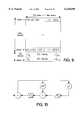
- FIG. 3is a diagrammatic view of a frame utilized in the data storage system of FIG. 1.
- FIG. 4is a flowchart generally showing steps involved in a recording process using the data storage system of FIG. 1.
- FIG. 5is a flowchart generally showing steps involved in a playback process using the data storage system of FIG. 1.
- FIG. 6is a diagrammatic view showing a flow of data from logical blocks to frames in the data storage system of FIG. 1.
- FIG. 7is a diagrammatic view showing a mapping of frames to disk sectors in the data storage system of FIG. 1.
- FIG. 8is a diagrammatic view showing embedded disk sector format and error correction information.
- FIG. 9is a diagrammatic view showing implementation of error correction in a frame data structure.
- FIG. 10is a schematic view of error correction logic utilized in the data storage system of FIG. 1.
- FIG. 11is a flowchart generally showing exemplary steps involved in signaling between a tape drive emulator and a removable disk drive in a recording process for the data storage system of FIG. 1.
- FIG. 12is a diagrammatic view showing a relationship between FIG. 12A and FIG. 12B.
- FIG. 12A and FIG. 12Bare flowcharts generally exemplary showing steps involved in signaling between a tape drive emulator and a removable disk drive in a playback process for the data storage system of FIG. 1.
- FIG. 13is a diagrammatic view showing contents of a frame index entry in a directory recorded on a disk by the storage system of FIG. 1.
- FIG. 14is a diagrammatic view showing a relative location of a directory in context of a format of a disk handled by the storage system of FIG. 1.
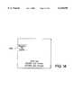
- FIG. 15is a diagrammatic view showing an example of usage of a directory recorded on a disk handled by the storage system of FIG. 1.
- FIG. 1shows a data storage system 20 according to an embodiment of the invention.
- Data storage system 20includes a removable disk drive 22 which handles a rotating magnetic disk 24, as well as tape drive emulator 30.
- disk drive 22employs transducing elements or heads and suitable electronics in order to transduce (i.e., record or playback) information in sector format on disk 24.
- the information recorded on disk 24 during recording or writingis ultimately obtained from host computer 40 in connection with, for example, a backup operation for storing computer data from host computer 40 on disk 24.
- a backup operationfor storing computer data from host computer 40 on disk 24.
- information obtained from disk 24 during playback or readingis ultimately applied to host computer 40 as can occur in a data restore operation, for example.
- tape drive emulator 30is connected to host computer 40 and appears to host computer 40 as a sequential storage system, e.g., a tape drive.
- cable 42 connecting host computer 40 with tape drive emulator 30carries data and signals including commands for a tape drive.
- tape drive emulator 30processes the data obtained from or applied to host computer 40 so that the data can be communicated to removable disk drive 22 over cable 44 in a manner compatible with a conventional removable disk drive.
- tape drive emulator 30imposes on the data (1) a data organization, imperceptible to disk drive 22, for rendering the data expressable and locatable in a tape drive format, and (2) an additional degree of error correction that provides enhanced data integrity necessary for data backup/restore operations.
- FIG. 2shows tape drive emulator 30 as comprising data formatter/deformatter 100 and a processor section 102.
- tape drive emulator 30has a host interface channel 104 and drive interface channel 106.
- Formatter/deformatter 100, processor section 102, host interface channel 104, and drive interface channel 106communicate over a PCI bus 110.
- PCI interfaces 112 and 114are provided for connecting respective host interface channel 104 and drive interface channel 106 to PCI bus 110.
- Host interface channel 104 and drive interface channel 106are constituted by suitable circuitry for processing signals and passing through data received from or applied to host computer 40 and disk drive 22, respectively.
- Drive interface channel 106is preferably a SCSI port which connects by cable 44 to disk drive 22.
- host interface channel 104is also preferably a SCSI port, but depending on the nature of cable 42 can also be an optical fiber-handling or other type channel, including an RF or IF channel.
- Processor section 102includes a microprocessor 120 which communicates over processor bus 122 to various memory elements including FEPROM 124 and RAM 126.
- Processor bus 122is also connected to a PCI-to-processor bus converter 130 which serves to interface and processor bus 122 with PCI bus 110.
- Formatter/deformatter 100connects to PCI bus 110 through PCI interface 150.
- Formatter/deformatter 100comprises a controller 160 which supervises, coordinates, and sequences operation of various engines or units, including compression and decompression engine 162, buffer block packer and unpacker 163; header generator 164; CRC generator 165; and ECC encoder and decoder 166.
- ECC encoder and decoder 166handles frame ECC bytes [depicted in the drawings as ECC-2], a layer of error correction which is above and beyond conventional disk drive ECC.
- formatter/deformatter 100includes a buffer manager 170 which is utilized by controller 160 and these engines and units for storing and retrieving data with respect to buffer 172.
- Buffer 172is a suitable memory chip, such as a RAM, in which data is stored in accordance with an organization formulated by buffer manager 170 in the manner hereinafter described e.g., with reference to FIG. 6.
- Another memory, particularly ECC RAM 180,is also provided in formatter/deformatter 100, but is accessible by ECC encoder and decoder 166 for purposes of e.g., intermediate storage error correction bytes, syndromes and the like generated by ECC encoder and decoder 166.
- FIG. 3shows a transparent organization imposed by formatter/deformatter 100 of tape drive emulator 30 on the data stored on disk 24.
- the data stored on disk 24is organized frames, one such frame 300 being shown in FIG. 3.
- Each frame 300is to be laid down on disk 24 in a data area of forty conventional disk sectors, the sectors being delineated for sake of illustration as horizontal lines (either solid or broken) in FIG. 3.
- the portion of frame 300 included in the data area of the first thirty eight sectorsare referenced herein as a "buffer block", while the data area of the last two sectors occupied by each frame 300 include the frame ECC bytes 308, or the enhanced or second tier ECC bytes.
- the first thirty two bytes of the data area of the first sector of frame 300serve as a frame header 310.
- the last four bytes of the data area of the thirty eighth sectorserve as buffer block CRC bytes 312.
- Compressed and packed user datalies between frame header 310 and buffer block CRC bytes 312.
- Pad bytes(indicated by reference numeral 314) are employed as necessary to fill in the user data area between frame header 310 and buffer block CRC bytes 312.
- frames such as frame 300can serve various purposes. Perhaps the most common employment of the frames is for actual user data. However, another type of frame is the directory frame. Directory frames contain index information as described in more detail in connection with FIG. 13, FIG. 14, and FIG. 15.
- FIG. 3shows a particular organization in which forty sectors comprise frame 300, it should be understood that frame size can vary in other embodiments. Any embodiments having variants in frame size should assure sufficient frame error correction in accordance with the frame size.
- FIG. 4shows basic steps depicted in a recording or write process in which user data from host computer 40 is recorded on disk 24.
- host computer 40transmits logical blocks of user data over cable 42 for reception at host interface channel 104 (see FIG. 2).
- the logical blocksare transmitted over PCI bus 110 to formatter/deformatter 100 and are stored, under control of buffer manager 170, in appropriate memory locations in buffer 172 (step 401).
- Step 402shows the logical blocks stored in buffer 172 being transferred, via buffer manager 170, to compression and decompression engine 162.
- Engine 162compresses the logical block using any one of several conventional data compression techniques, and then (via buffer manager 170) returns the logical blocks to buffer 172 as indicated by step 403.
- FIG. 6shows an illustrative section 172A of buffer 172 in which logical blocks obtained from host computer 40 are stored in accordance with step 401.
- Section 172B of buffer 172 as depicted in FIG. 6shows compression of logical blocks after the compression of step 402.
- a set of compressed logical blocksare packed into a buffer block.
- a buffer blockwill be laid down in the data area of the first thirty eight sectors of a forty sector frame 300 (see FIG. 3).
- a memory locationsuch as section 172B is transmitted via buffer manager 170 to buffer block packer and unpacker 163 (see FIG. 2) for generation of a buffer block.
- the packed buffer blockis returned to buffer 172.
- Step 405involves generation of both frame header 310 and buffer block CRC bytes 312 (see FIG. 3) for the buffer block.
- Frame header 310 and buffer block CRC bytes 312are generated by header generator 164 and CRC generator 165, respectively, under supervision of controller 160 in a manner understood by those skilled in the art.
- Fame header 310includes control and identification information which conveys frame sequence number, frame type, control flags related to the packing of logical blocks in the frame, logical block count, file mark count, setmark count, and partition number.
- FIG. 6shows as section 172C the contents of a buffer block upon insertion therein of frame header 310 and buffer block CRC bytes 312 upon completion of steps 405, as well as insertion of pad bytes 314.
- Pad bytes 314can be generated by a separate unillustrated pad byte generator, or alternatively by other elements such as controller 160.
- Step 406shows that the buffer block is transmitted to ECC encoder and decoder 166 whereat the buffer block is utilized to generate frame ECC bytes over the entire buffer block.
- a frame 300is formed as shown in section 172D of FIG. 6.
- the frame ECC bytes 308ultimately comprise two sectors of frame 300.
- Step 407shows the frame being transmitted from buffer 172 to removable disk drive 22, as well as recording by disk drive 22 in accordance with its conventional operation on disk 24.
- the transmissioninvolves retrieval of the frame from buffer 172 by buffer manager 170 and application of the frame to PCI bus 110 (via PCI interface 150) and then to drive interface 106 and cable 44.
- FIG. 3shows how frame 300 corresponds to sectors of the disk 24, it being remembered that a frame utilizes the data areas of forty sectors of disk 24.
- FIG. 7shows the recording of frame 300 on disk 24, the sectors of disk 24 each having a corresponding logical block address number (e.g., LBA #n, LBA #n+1, etc.).
- LBAsdisk sectors are addressed as "LBAs".
- the LBAs of disk 24are numbered consecutively from zero up to the maximum the disk can store. All LBAs represent defect-free physical sectors on disk 24, and hence do not necessarily represent contiguous physical locations on disk 24.
- Each sectorincludes preamble area 202; a sector data area 204; and sector postamble area 206.
- Sector preamble area 202includes sector identification information such as a sector synchronization field, a sector identification number, and various control bytes.
- Sector data area 204includes the 512 user data bytes (which gives sector 200 the denomination as a "512 byte" sector), as well as disk drive-generated sector error correction bytes.
- sixteen sector ECC bytes(shown in the drawings as ECC-1) are generated over each of four groupings of one hundred six data bytes.
- sixteen sector ECC bytesare generated over a set of bytes comprising the last eighty eight data bytes of the sector, four disk drive-generated CRC bytes of the sector, and disk drive-generated fourteen control bytes of the sector.
- All information in sector 200 of FIG. 8 except the 512 data bytesare generated by the disk drive 22 for inclusion in sector 200.
- the 512 data bytesare obtained from a portion of a frame 300 generated by tape drive emulator 30 (e.g., a portion of frame 300 corresponding to one horizontal row of FIG. 3).
- the disk drive-generated sector ECC bytescover essentially only the 512 data bytes of sector 200 shown in FIG. 8. Importantly, the disk drive-generated sector ECC bytes do not cover the information included in sector preamble area 202. Therefore, if sector 200 is not deemed a defective sector at manufacturing, but sector 200 later becomes contaminated e.g., by manipulation of removable disk 24, an error in sector preamble area 202 cannot be corrected by the error correction techniques employed by disk drive 22. For example, an error occurring in sector preamble area 202 could render the entire sector 200 irretrievable and/or unreadable.
- the present inventionovercomes the problem of an error in portions of sector 200 such as sector preamble area 202.
- inability of disk drive 22 to obtain or read an entire sector 200 from disk 24is essentially immaterial to operation of data storage system 20.
- the provision of frame error correction bytes 308enable tape drive emulator 30 to generate as many as two sectors of a frame which otherwise would be unreadable by disk drive 22.
- FIG. 5shows basic steps involved in playing back, e.g., reading, information recorded on removable disk 24.
- tape drive emulator 30issues to tape drive 22 a read command to transfer data to tape drive emulator 30.
- the read command issued from tape drive emulator 30 to transfer datais in response to a similar command issued to tape drive emulator 30 from host computer 40. Since host computer 40 thinks that it is connected to a tape drive, its command to tape drive emulator 30 will prompt tape drive emulator 30 to request a frame of data from disk drive 22.
- disk drive 22obtains forty sectors from disk 24. As indicated by step 501, the sector data areas of these forty sectors (which constitutes a frame) are transferred over cable 40 to tape drive emulator 30.
- the sectorsare transmitted through drive interface channel 106 to PCI bus 110 (via PCI interface 114) and (via PCI interface 150 and buffer manager 170) into an appropriate location (e.g., next available location) in buffer 172.
- Section 172D of FIG. 6shows the contents of a frame upon receipt from disk drive 22.
- the frame just obtained from disk drive 24is transferred (via buffer manager 170) to ECC encoder and decoder 166 for an integrity check.
- ECC encoder and decoder 166which performs an error location operation to determine at step 503 whether any errors reside in the frame (e.g., if syndromes generated by ECC encoder and decoder 166 indicate any errors) and the location of such errors (e.g., by generation of an error locator polynomial). If any errors are detected in the frame, steps 504-506 are executed before resuming execution at step 508.
- tape drive emulator 30issues to disk drive 22 a special command to obtain, for the erroneous sector(s) of the frame just read, not only the 512 data bytes, but also the eighty sector ECC bytes which cover sector data area 204 (see FIG. 8).
- the special type of command which obtains the sector ECC bytes in addition to user data bytesis commonly called a READ LONG command. Such a READ LONG command enables recovery of all six hundred ten bytes of sector data area 204 at the disk drive SCSI interface.
- ECC encoder and decoder 166uses both the sector ECC bytes and the frame ECC bytes 308 (see FIG. 3) in order to generate correction bytes which are substituted into the erroneous bytes indicated by the error locator polynomial. Error correction performed by ECC encoder and decoder 166 is hereinafter described in more detail with reference to FIG. 9 and FIG. 10. If it turns out that the frame is uncorrectable, an error message is sent to host computer 40 as indicated by step 507. Otherwise, the corrected frame is returned (via buffer manager 170) to buffer 172 and execution continues with step 508.
- Step 508involves controller 160 reading header bytes 310 of the frame (see FIG. 3) in order to obtain identification information from the frame.
- the buffer blocke.g., corresponding to the first thirty eight sectors of the frame
- the buffer blockis sent via buffer manager 170 to buffer block packer & unpacker 163 where the buffer block is unpacked and returned to buffer 172.
- the unpacking of the buffer blockis represented by the transition from section 172C to 172B in FIG. 6.
- the unpacked but still-compressed logical blocks obtained from the buffer blockare next sent from buffer 172 to compression and decompression engine 162 where (at step 511) the logical blocks are decompressed.
- the decompressed datais then loaded into an appropriate location in buffer 172, with the decompressed data now being allocated in logical blocks as shown by section 172A in FIG. 6.
- Step 512shows the logical blocks being transmitted from tape drive emulator 30 to host computer 40.
- the logical blocksare obtained by buffer manager 170 from buffer 172, and applied via PCI interface 150 to PCI bus 110 to host interface channel 104 (via PCI interface 112). From host interface channel 104 the logical blocks are applied on cable 42 to host computer 40 in conventional manner.
- FIG. 9shows how byte position assignments are allocated within frame 300, the nomenclature b j ,k being employed to depict byte position with the matrix of the frame, "j" being the row and "k” being the column.
- the ECC generator polynomial for the frame ECC bytesis given by:
- FIG. 10is a block diagram of an implementation of G(x), the arrow from the left indicating introduction of data bytes b0,k . . . b37,k, where k is the column number which ranges from zero to 511.
- x 0 k and x 1 kare the frame ECC bytes for column k.
- FIG. 11shows basic steps involved in write or recording signaling between tape drive emulator 30 and drive 22
- FIG. 12A and FIG. 12Bshow basic steps involved in playback or read signaling between tape drive emulator 30 and drive 22.
- step 11-1tape drive emulator 30 sends a SCSI WRITE command to disk drive 22, specifying that forty sectors be written beginning in location block address (LBA) #n.
- Step 11-2depicts the transfer of frame 300 (see FIG. 3), prepared in the manner described above e.g., with reference to FIG. 4, over cable 44 to disk drive 22.
- step 11-3disk drive 22 determines whether the recording on disk 24 was successfully completed. If the recording on disk 24 was successful, at step 11-4 disk drive 22 sends a COMMAND COMPLETE message to tape drive emulator 30.
- tape drive emulator 30increments the LBA address "n" by forty sectors (step 11-6) and sends another SCSI WRITE command to disk drive 22 (11-1). The loop of steps 11-1 through 11-6 continues as long as host computer 40 has more frames to record.
- disk drive 22sends a COMMAND COMPLETE message with a check condition status to tape drive emulator 30.
- tape drive emulator 30sends a REQUEST SENSE command to disk drive 22 to query the error status.
- disk drive 22Upon receipt of the query of error status, disk drive 22 sends a sense data and COMMAND COMPLETE message to tape drive emulator 30 as step 11-10.
- tape drive emulator 30reads the sense data and sends an error message to host computer 40.
- FIG. 12A and FIG. 12Bshow basic steps involved in playback or read signaling between tape drive emulator 30 and drive 22.
- host computer 40requires data from the storage medium (e.g., disk 24)
- a READ commandis issued to tape drive emulator 30.
- step 12-1shows tape drive emulator 30 sending a SCSI READ command and to disk drive 22, specifically requesting that forty sectors (e.g., a frame) be read from a specified location (e.g., LBA #n).
- SCSI READ commandUpon receipt of the SCSI READ command, disk drive 22 transfers forty sectors worth of sector data area over cable 44 to tape drive emulator 30 (step 12-2). In addition, disk drive 22 determines whether its read operation was successfully completed (step 12-3).
- disk drive 22sends a COMMAND COMPLETE message with a good status to tape drive emulator 30 (step 12-4). Then, if host computer 40 still requests more frames (determined at step 12-5), tape drive emulator 30 increments the logical block address (LBA #n) by forty sectors (step 12-6) and issues a further SCSI READ command (step 12-2) to disk drive 22. The reading of frames from disk 24 continues in this manner until it is determined at step 12-5 that host computer 40 has no further present requirement for data.
- LBA #nlogical block address
- disk drive 22sends a COMMAND COMPLETE message with a CHECK CONDITION status to tape drive emulator 30.
- tape drive emulator 30Upon noting the CHECK CONDITION status, at step 12-9 tape drive emulator 30 sends a REQUEST SENSE command to disk drive 22 in order to query the error status.
- disk drive 22sends sense data with medium error status and a COMMAND COMPLETE message to tape drive emulator 30.
- tape drive emulator 30reads the sense data and enters an error recovery mode sequence which is particularly depicted in FIG. 12B.
- tape drive emulator 30issues a READ LONG command to disk drive 22 for the sector noted as containing an error.
- the READ LONG commandcauses disk drive 22 to transfer to tape drive emulator 30 not only the 512 data bytes of the data area 204 (see FIG. 8), but also the sector ECC bytes generated by disk drive 22 and stored in sector data area 204.
- ECC encoder and decoder 166 of tape drive emulator 30identifies the location of the error in the sector using the sector ECC bytes obtained from disk drive 22. Further, uses ECC encoder and decoder 166 then uses the frame ECC bytes obtained from the frame in order to perform error correction on the erroneous bytes. Thereafter, ECC encoder and decoder 166 checks the frame and its correction process by using the buffer block CRC bytes 312 (see FIG. 3) as shown in step 12-15. If the check at step 12-15 confirms that the data of the frame is correct (step 12-16), the error recovery mode sequence is terminated and execution continues with step 12-5 (to determine if other frames are required by host computer 40). Otherwise, at step 12-17 an error message is sent to host computer 40, indicating that the requested data is uncorrectable.
- a directory 1400is a special block of frames on disk 24 which contains a frame index.
- the frame indexis comprised of frame index entries, the format of one such frame index entry 1300 being shown in FIG. 13.
- the purpose of directory 1400is to facilitate location by tape drive emulator 30 of the logical block addresses (LBAs) of specific data items (e.g., by logical block number or file number) stored in the frame structure on the data area of the disk.
- LBAslogical block addresses
- Frame index entry 1300generated for each frame 300 (see FIG. 3) recorded on disk 24.
- the frame index entriesare packed into directory frames (by buffer block packer and unpacker unit 163) and recorded on the disk 24.
- 1294 frame index entriesare stored in each directory frame.
- Directory 1400is thus comprised of enough frames to store all frame index entries.
- Directory 1400is recorded at a specific location on disk, e.g., starting at logical block address #0).
- FIG. 13shows the format of frame index entry 1300.
- Each frame index entry 1300has fifteen bytes.
- Frame index entry 1300has a first field 1301 which contains four bytes of a frame starting LBA; a second field 1302 which contains the first logical block number in the frame (four bytes); a third frame field 1303 which contains the first file number in the frame (four bytes); and, a fourth frame field 1304 which contains the first setmark number in the frame (three bytes).
- a removable disk drivehas a disk with a storage capacity of 20 GB.
- Such a diskhas a capacity for 976,562 frames.
- the corresponding 976,562 frame index entriesrequires that directory 1400 have seven hundred fifty five frames.
- FIG. 15provides an illustration of usage of directory 1400. It is assumed that host computer 40 issues a command to locate logical block #100 (LB #100). Upon receipt of such a command, tape drive emulator 30 sends a command to tape drive 22 (depicted by arrow 15-1) so that tape drive 22 reads directory 1400 of tape to identify the directory frame which contains a frame index entry for logical block LB #100. Upon receipt of the directory frame (depicted by arrow 15-2), a portion of which is shown as 1300-15 in FIG. 15, tape drive emulator 30 locates the frame index entry which indicates in which disk LBA the requested logical block (i.e., logical block LB #100) resides. As shown in FIG.
- a frame recorded at disk LBA 1040begins with logical block 90 and a frame recorded at disk LBA 1080 begins with logical block 105, meaning that the frame recorded at disk LBA 1040 has logical block #100 stored thereon.
- arrow 15-3points to the frame recorded at disk LBA 1040 which has the sought logical block #100.
- tape drive emulator 30issues a command to disk drive 22 for disk drive 22 to read the frame which includes logical block #100, i.e., the frame beginning at LBA 1040, as indicated by arrow 15-4.
- logical block #100is read and provided to host computer 40.
- each frame index entry 1300contains the first logical block number, the first file number, and the first set mark number stored in each frame.
- a specific itemis located by searching for the highest entry below (or equal to ) the desired item.
- the associated logical block address (LBA)points to the frame where the beginning of the desired data item is located.
- the present inventionthus applies an additional logical format to allow a disk to be operated as a "virtual" tape backup device.
- the present inventionadds additional ECC, herein known as frame ECC, to the embedded format of removable disk drive 22 to enhance its data reliability.
- ECCherein known as frame ECC
- the present inventionincreases data reliability of a removable disk drive by about ten orders of magnitude.
- the tape drive emulator 30 of the present inventionemulates the operation of a tape drive using a removable disk medium.
- the tape drive emulator 30is advantageous since software written for data backup applications presently assumes that the data is recorded to a tape drive.
- Tape drivesbeing sequential in nature, use a different set of commands and functions to write, read, and locate data than do disk drives.
- One of those features, which is included in the present invention, but not present in disk drives,is data delineators or delimiters such as file marks and set marks, as well as the ability to search for data based on delineator or delimiter types (logical blocks, file number, setmark number, etc.).
- the directory 1400 of the present inventionparticularly facilitates such searching and location.
- tape drive emulator 30can be provided separately (e.g., apart from disk drive 22).
Landscapes
- Engineering & Computer Science (AREA)
- Theoretical Computer Science (AREA)
- Physics & Mathematics (AREA)
- General Engineering & Computer Science (AREA)
- General Physics & Mathematics (AREA)
- Human Computer Interaction (AREA)
- Quality & Reliability (AREA)
- Signal Processing For Digital Recording And Reproducing (AREA)
Abstract
Description
G(x)=(x+α.sup.0)(x+α.sup.1)
G(x)=x.sup.2 +x(α.sup.0 +α.sup.1) +α.sup.0 α.sup.1 =x.sup.2 +α.sup.25 x+α.sup.1
Claims (36)
Priority Applications (4)
| Application Number | Priority Date | Filing Date | Title |
|---|---|---|---|
| US08/905,326US6128698A (en) | 1997-08-04 | 1997-08-04 | Tape drive emulator for removable disk drive |
| US09/045,691US6389503B1 (en) | 1997-08-04 | 1998-03-23 | Tape drive emulation by removable disk drive and media formatted therefor |
| PCT/US1998/016089WO1999006912A1 (en) | 1997-08-04 | 1998-08-04 | Tape drive emulation by removable disk drive and media formatted therefor |
| AU86841/98AAU8684198A (en) | 1997-08-04 | 1998-08-04 | Tape drive emulation by removable disk drive and media formatted therefor |
Applications Claiming Priority (1)
| Application Number | Priority Date | Filing Date | Title |
|---|---|---|---|
| US08/905,326US6128698A (en) | 1997-08-04 | 1997-08-04 | Tape drive emulator for removable disk drive |
Related Child Applications (1)
| Application Number | Title | Priority Date | Filing Date |
|---|---|---|---|
| US09/045,691Continuation-In-PartUS6389503B1 (en) | 1997-08-04 | 1998-03-23 | Tape drive emulation by removable disk drive and media formatted therefor |
Publications (1)
| Publication Number | Publication Date |
|---|---|
| US6128698Atrue US6128698A (en) | 2000-10-03 |
Family
ID=25420637
Family Applications (1)
| Application Number | Title | Priority Date | Filing Date |
|---|---|---|---|
| US08/905,326Expired - LifetimeUS6128698A (en) | 1997-08-04 | 1997-08-04 | Tape drive emulator for removable disk drive |
Country Status (1)
| Country | Link |
|---|---|
| US (1) | US6128698A (en) |
Cited By (65)
| Publication number | Priority date | Publication date | Assignee | Title |
|---|---|---|---|---|
| US6339810B1 (en)* | 2000-01-11 | 2002-01-15 | International Business Machines Corporation | Serial data storage system with automatically adjusted data protection to implement worm media with limited overwrite allowing write appending |
| US6400657B1 (en)* | 1999-06-09 | 2002-06-04 | Hitachi, Ltd. | Method of selecting medium in optical disk memory device and optical disk memory system |
| US20020144044A1 (en)* | 2001-03-29 | 2002-10-03 | Moon William G. | Removable disk storage array emulating tape library having backup and archive capability |
| US6490648B1 (en)* | 1999-07-23 | 2002-12-03 | Hitachi, Ltd. | Virtual tape storage apparatus |
| US20030135672A1 (en)* | 2002-01-14 | 2003-07-17 | Imation Corp. | System having tape drive emulator and data cartridge carrying a non-tape storage medium |
| US20030177149A1 (en)* | 2002-03-18 | 2003-09-18 | Coombs David Lawrence | System and method for data backup |
| US20030182593A1 (en)* | 2002-03-19 | 2003-09-25 | International Business Machines Corporation | Failover system for storage area network |
| US6636942B2 (en) | 2001-10-05 | 2003-10-21 | International Business Machines Corporation | Storage structure for storing formatted data on a random access medium |
| US6654851B1 (en)* | 2000-03-14 | 2003-11-25 | International Business Machine Corporation | System, apparatus, and method for using a disk drive for sequential data access |
| US20040034811A1 (en)* | 2002-08-14 | 2004-02-19 | Alacritus, Inc. | Method and system for copying backup data |
| US20040045002A1 (en)* | 2000-10-05 | 2004-03-04 | Ricardo Berger | Method system and apparatus for multiprocessing |
| US20040044863A1 (en)* | 2002-08-30 | 2004-03-04 | Alacritus, Inc. | Method of importing data from a physical data storage device into a virtual tape library |
| US20040044842A1 (en)* | 2002-08-30 | 2004-03-04 | Alacritus, Inc. | System and method for exporting a virtual tape |
| US20040098244A1 (en)* | 2002-11-14 | 2004-05-20 | Imation Corp. | Method and system for emulating tape storage format using a non-tape storage medium |
| US20040148458A1 (en)* | 2003-01-27 | 2004-07-29 | Michiaki Sekine | Method and system for tape management |
| US6779080B2 (en) | 2000-01-11 | 2004-08-17 | International Business Machines Corporation | Serial data storage system with automatically adjusted data protection to implement worm media with limited overwrite allowing write appending |
| US20040181388A1 (en)* | 2003-03-11 | 2004-09-16 | Yung Yip | System having tape drive emulator and data tape cartridge housing carrying multiple disk drives |
| US20040181628A1 (en)* | 2003-03-12 | 2004-09-16 | Alacritus, Inc. | System and method for virtual vaulting |
| US20040243745A1 (en)* | 2003-04-28 | 2004-12-02 | Bolt Thomas B. | Data storage and protection apparatus and methods of data storage and protection |
| US20040260967A1 (en)* | 2003-06-05 | 2004-12-23 | Copan Systems, Inc. | Method and apparatus for efficient fault-tolerant disk drive replacement in raid storage systems |
| US20050060618A1 (en)* | 2003-09-11 | 2005-03-17 | Copan Systems, Inc. | Method and system for proactive drive replacement for high availability storage systems |
| US20050114598A1 (en)* | 2003-11-24 | 2005-05-26 | Copan Systems, Inc. | Method and system for accessing plurality of storage devices |
| US20050120168A1 (en)* | 1999-08-20 | 2005-06-02 | Emc Corporation, A Massachusetts Corporation | Digital data storage subsystem with directory including check values for verifying during an information retrieval operation that retrieved information was the desired information |
| US20050165998A1 (en)* | 2002-02-13 | 2005-07-28 | Quantum Corporation | Use of the universal serial bus as an internal architecture within IDE disk array |
| US20050210304A1 (en)* | 2003-06-26 | 2005-09-22 | Copan Systems | Method and apparatus for power-efficient high-capacity scalable storage system |
| US20050227569A1 (en)* | 2001-09-03 | 2005-10-13 | Matsushita Electric Industrial Co., Ltd. | Light-emitting semiconductor device, light-emitting system and method for fabricating light-emitting semiconductor device |
| US20060075283A1 (en)* | 2004-09-30 | 2006-04-06 | Copan Systems, Inc. | Method and apparatus for just in time RAID spare drive pool management |
| US20060090098A1 (en)* | 2003-09-11 | 2006-04-27 | Copan Systems, Inc. | Proactive data reliability in a power-managed storage system |
| US20060112138A1 (en)* | 2004-11-03 | 2006-05-25 | Spectra Logic Corporation | File formatting on a non-tape media operable with a streaming protocol |
| US20070094533A1 (en)* | 2002-03-18 | 2007-04-26 | Net Integration Technologies Inc. | System and method for data backup |
| US20070220316A1 (en)* | 2002-09-03 | 2007-09-20 | Copan Systems, Inc. | Method and Apparatus for Power-Efficient High-Capacity Scalable Storage System |
| US20070260815A1 (en)* | 2002-09-03 | 2007-11-08 | Copan Systems | Background processing of data in a storage system |
| US7308528B2 (en) | 2003-08-04 | 2007-12-11 | Hitachi, Ltd. | Virtual tape library device |
| US20070299996A1 (en)* | 2006-06-27 | 2007-12-27 | Gideon Guy | Data Transfer Device |
| US7315965B2 (en) | 2004-02-04 | 2008-01-01 | Network Appliance, Inc. | Method and system for storing data using a continuous data protection system |
| US7325159B2 (en) | 2004-02-04 | 2008-01-29 | Network Appliance, Inc. | Method and system for data recovery in a continuous data protection system |
| US20080059144A1 (en)* | 2006-09-01 | 2008-03-06 | Inphase Technologies | Emulation of dissimilar removable medium storage device types assisted by information embedded in the logical format |
| US7401198B2 (en) | 2005-10-06 | 2008-07-15 | Netapp | Maximizing storage system throughput by measuring system performance metrics |
| US7406488B2 (en) | 2004-02-04 | 2008-07-29 | Netapp | Method and system for maintaining data in a continuous data protection system |
| US7426617B2 (en) | 2004-02-04 | 2008-09-16 | Network Appliance, Inc. | Method and system for synchronizing volumes in a continuous data protection system |
| US7437492B2 (en) | 2003-05-14 | 2008-10-14 | Netapp, Inc | Method and system for data compression and compression estimation in a virtual tape library environment |
| US7437387B2 (en) | 2002-08-30 | 2008-10-14 | Netapp, Inc. | Method and system for providing a file system overlay |
| US7454529B2 (en) | 2002-08-02 | 2008-11-18 | Netapp, Inc. | Protectable data storage system and a method of protecting and/or managing a data storage system |
| US7490103B2 (en) | 2004-02-04 | 2009-02-10 | Netapp, Inc. | Method and system for backing up data |
| US7526620B1 (en) | 2004-12-14 | 2009-04-28 | Netapp, Inc. | Disk sanitization in an active file system |
| US7533323B2 (en) | 2005-07-28 | 2009-05-12 | Prostor Systems, Inc. | Adaptive archival format |
| US7559088B2 (en) | 2004-02-04 | 2009-07-07 | Netapp, Inc. | Method and apparatus for deleting data upon expiration |
| US7558839B1 (en) | 2004-12-14 | 2009-07-07 | Netapp, Inc. | Read-after-write verification for improved write-once-read-many data storage |
| US7567993B2 (en) | 2002-12-09 | 2009-07-28 | Netapp, Inc. | Method and system for creating and using removable disk based copies of backup data |
| US7581118B2 (en) | 2004-12-14 | 2009-08-25 | Netapp, Inc. | Disk sanitization using encryption |
| US7650533B1 (en) | 2006-04-20 | 2010-01-19 | Netapp, Inc. | Method and system for performing a restoration in a continuous data protection system |
| US7720817B2 (en) | 2004-02-04 | 2010-05-18 | Netapp, Inc. | Method and system for browsing objects on a protected volume in a continuous data protection system |
| US7747816B1 (en)* | 2003-03-31 | 2010-06-29 | Ultera Systems, Inc. | Virtual tape stacker |
| US7752401B2 (en) | 2006-01-25 | 2010-07-06 | Netapp, Inc. | Method and apparatus to automatically commit files to WORM status |
| US7774610B2 (en) | 2004-12-14 | 2010-08-10 | Netapp, Inc. | Method and apparatus for verifiably migrating WORM data |
| US7783606B2 (en) | 2004-02-04 | 2010-08-24 | Netapp, Inc. | Method and system for remote data recovery |
| US20100302262A1 (en)* | 2009-05-28 | 2010-12-02 | Tandberg Data Corporation | Display for information storage module |
| US7882081B2 (en) | 2002-08-30 | 2011-02-01 | Netapp, Inc. | Optimized disk repository for the storage and retrieval of mostly sequential data |
| US7904679B2 (en) | 2004-02-04 | 2011-03-08 | Netapp, Inc. | Method and apparatus for managing backup data |
| US8024172B2 (en)* | 2002-12-09 | 2011-09-20 | Netapp, Inc. | Method and system for emulating tape libraries |
| US8028135B1 (en) | 2004-09-01 | 2011-09-27 | Netapp, Inc. | Method and apparatus for maintaining compliant storage |
| US8780480B2 (en)* | 2011-05-24 | 2014-07-15 | Seagate Technology Llc | Presentation of shingled magnetic recording device to a host device resource manager |
| US8862962B2 (en)* | 2012-10-03 | 2014-10-14 | Lsi Corporation | Layered decoder enhancement for retained sector reprocessing |
| US20150205804A1 (en)* | 2007-10-05 | 2015-07-23 | Imation Corp. | Archiving system with partitions of individual archives |
| US9240210B2 (en)* | 2013-11-26 | 2016-01-19 | Seagate Technology Llc | Physical subsector error marking |
Citations (15)
| Publication number | Priority date | Publication date | Assignee | Title |
|---|---|---|---|---|
| US3955180A (en)* | 1974-01-02 | 1976-05-04 | Honeywell Information Systems Inc. | Table driven emulation system |
| US4467421A (en)* | 1979-10-18 | 1984-08-21 | Storage Technology Corporation | Virtual storage system and method |
| US4511963A (en)* | 1982-08-30 | 1985-04-16 | International Business Machines Corp. | Emulation of special purpose magnetic tape data recording equipment by a general purpose processor |
| US4727512A (en)* | 1984-12-06 | 1988-02-23 | Computer Design & Applications, Inc. | Interface adaptor emulating magnetic tape drive |
| US4730321A (en)* | 1986-05-30 | 1988-03-08 | Quantum Corporation | Disk drive with improved error correction code |
| US4775969A (en)* | 1986-05-15 | 1988-10-04 | Aquidneck Systems International, Inc. | Optical disk storage format, method and apparatus for emulating a magnetic tape drive |
| US4947367A (en)* | 1988-03-28 | 1990-08-07 | Emc Corporation | System for converting digital data from magnetic tape format apparatus and method for converting a sequentially accessible magnetic tape data format to directly accessible write-once disk data format to worm optical disk format |
| US5075805A (en)* | 1988-02-25 | 1991-12-24 | Tandon Corporation | Disk drive controller system |
| US5297124A (en)* | 1992-04-24 | 1994-03-22 | Miltope Corporation | Tape drive emulation system for a disk drive |
| US5301304A (en)* | 1988-05-20 | 1994-04-05 | International Business Machines Corporation | Emulating records in one record format in another record format |
| US5438674A (en)* | 1988-04-05 | 1995-08-01 | Data/Ware Development, Inc. | Optical disk system emulating magnetic tape units |
| US5455926A (en)* | 1988-04-05 | 1995-10-03 | Data/Ware Development, Inc. | Virtual addressing of optical storage media as magnetic tape equivalents |
| US5642497A (en)* | 1995-01-30 | 1997-06-24 | Tektronix, Inc. | Digital disk recorder using a port clock having parallel tracks along a timeline with each track representing an independently accessible media stream |
| US5778395A (en)* | 1995-10-23 | 1998-07-07 | Stac, Inc. | System for backing up files from disk volumes on multiple nodes of a computer network |
| US5802398A (en)* | 1990-11-13 | 1998-09-01 | Synchrome Technology, Inc. | Method and apparatus for allowing communication between a host computer and at least two storage devices over a single interface |
- 1997
- 1997-08-04USUS08/905,326patent/US6128698A/ennot_activeExpired - Lifetime
Patent Citations (15)
| Publication number | Priority date | Publication date | Assignee | Title |
|---|---|---|---|---|
| US3955180A (en)* | 1974-01-02 | 1976-05-04 | Honeywell Information Systems Inc. | Table driven emulation system |
| US4467421A (en)* | 1979-10-18 | 1984-08-21 | Storage Technology Corporation | Virtual storage system and method |
| US4511963A (en)* | 1982-08-30 | 1985-04-16 | International Business Machines Corp. | Emulation of special purpose magnetic tape data recording equipment by a general purpose processor |
| US4727512A (en)* | 1984-12-06 | 1988-02-23 | Computer Design & Applications, Inc. | Interface adaptor emulating magnetic tape drive |
| US4775969A (en)* | 1986-05-15 | 1988-10-04 | Aquidneck Systems International, Inc. | Optical disk storage format, method and apparatus for emulating a magnetic tape drive |
| US4730321A (en)* | 1986-05-30 | 1988-03-08 | Quantum Corporation | Disk drive with improved error correction code |
| US5075805A (en)* | 1988-02-25 | 1991-12-24 | Tandon Corporation | Disk drive controller system |
| US4947367A (en)* | 1988-03-28 | 1990-08-07 | Emc Corporation | System for converting digital data from magnetic tape format apparatus and method for converting a sequentially accessible magnetic tape data format to directly accessible write-once disk data format to worm optical disk format |
| US5438674A (en)* | 1988-04-05 | 1995-08-01 | Data/Ware Development, Inc. | Optical disk system emulating magnetic tape units |
| US5455926A (en)* | 1988-04-05 | 1995-10-03 | Data/Ware Development, Inc. | Virtual addressing of optical storage media as magnetic tape equivalents |
| US5301304A (en)* | 1988-05-20 | 1994-04-05 | International Business Machines Corporation | Emulating records in one record format in another record format |
| US5802398A (en)* | 1990-11-13 | 1998-09-01 | Synchrome Technology, Inc. | Method and apparatus for allowing communication between a host computer and at least two storage devices over a single interface |
| US5297124A (en)* | 1992-04-24 | 1994-03-22 | Miltope Corporation | Tape drive emulation system for a disk drive |
| US5642497A (en)* | 1995-01-30 | 1997-06-24 | Tektronix, Inc. | Digital disk recorder using a port clock having parallel tracks along a timeline with each track representing an independently accessible media stream |
| US5778395A (en)* | 1995-10-23 | 1998-07-07 | Stac, Inc. | System for backing up files from disk volumes on multiple nodes of a computer network |
Cited By (91)
| Publication number | Priority date | Publication date | Assignee | Title |
|---|---|---|---|---|
| US6400657B1 (en)* | 1999-06-09 | 2002-06-04 | Hitachi, Ltd. | Method of selecting medium in optical disk memory device and optical disk memory system |
| US6490648B1 (en)* | 1999-07-23 | 2002-12-03 | Hitachi, Ltd. | Virtual tape storage apparatus |
| US7159139B2 (en)* | 1999-08-20 | 2007-01-02 | Emc Corporation | Digital data storage subsystem including directory for efficiently providing formatting information for stopped records and utilization of a check value for verifying that a record is from a particular storage location |
| US20050120168A1 (en)* | 1999-08-20 | 2005-06-02 | Emc Corporation, A Massachusetts Corporation | Digital data storage subsystem with directory including check values for verifying during an information retrieval operation that retrieved information was the desired information |
| US6779080B2 (en) | 2000-01-11 | 2004-08-17 | International Business Machines Corporation | Serial data storage system with automatically adjusted data protection to implement worm media with limited overwrite allowing write appending |
| US6339810B1 (en)* | 2000-01-11 | 2002-01-15 | International Business Machines Corporation | Serial data storage system with automatically adjusted data protection to implement worm media with limited overwrite allowing write appending |
| US6654851B1 (en)* | 2000-03-14 | 2003-11-25 | International Business Machine Corporation | System, apparatus, and method for using a disk drive for sequential data access |
| US20040045002A1 (en)* | 2000-10-05 | 2004-03-04 | Ricardo Berger | Method system and apparatus for multiprocessing |
| US6957291B2 (en)* | 2001-03-29 | 2005-10-18 | Quantum Corporation | Removable disk storage array emulating tape library having backup and archive capability |
| US20020144044A1 (en)* | 2001-03-29 | 2002-10-03 | Moon William G. | Removable disk storage array emulating tape library having backup and archive capability |
| US20060010275A1 (en)* | 2001-03-29 | 2006-01-12 | Quantum Corporation | Removable disk storage array emulating tape library having backup and archive capability |
| US20050227569A1 (en)* | 2001-09-03 | 2005-10-13 | Matsushita Electric Industrial Co., Ltd. | Light-emitting semiconductor device, light-emitting system and method for fabricating light-emitting semiconductor device |
| US6636942B2 (en) | 2001-10-05 | 2003-10-21 | International Business Machines Corporation | Storage structure for storing formatted data on a random access medium |
| US20040190216A1 (en)* | 2002-01-14 | 2004-09-30 | Yung Yip | Static dissipative housing for data cartridge carrying non-tape storage medium |
| US20030135672A1 (en)* | 2002-01-14 | 2003-07-17 | Imation Corp. | System having tape drive emulator and data cartridge carrying a non-tape storage medium |
| US20050165998A1 (en)* | 2002-02-13 | 2005-07-28 | Quantum Corporation | Use of the universal serial bus as an internal architecture within IDE disk array |
| US20070094533A1 (en)* | 2002-03-18 | 2007-04-26 | Net Integration Technologies Inc. | System and method for data backup |
| US7702867B2 (en) | 2002-03-18 | 2010-04-20 | International Business Machines Corporation | System and method for data backup |
| US20030177149A1 (en)* | 2002-03-18 | 2003-09-18 | Coombs David Lawrence | System and method for data backup |
| US6952792B2 (en) | 2002-03-19 | 2005-10-04 | International Business Machines Corporation | Failover system for storage area network |
| US20030182593A1 (en)* | 2002-03-19 | 2003-09-25 | International Business Machines Corporation | Failover system for storage area network |
| US7454529B2 (en) | 2002-08-02 | 2008-11-18 | Netapp, Inc. | Protectable data storage system and a method of protecting and/or managing a data storage system |
| US7069466B2 (en) | 2002-08-14 | 2006-06-27 | Alacritus, Inc. | Method and system for copying backup data |
| US20040034811A1 (en)* | 2002-08-14 | 2004-02-19 | Alacritus, Inc. | Method and system for copying backup data |
| US20040044842A1 (en)* | 2002-08-30 | 2004-03-04 | Alacritus, Inc. | System and method for exporting a virtual tape |
| US6862656B2 (en) | 2002-08-30 | 2005-03-01 | Alacritus, Inc. | System and method for exporting a virtual tape |
| US6851031B2 (en) | 2002-08-30 | 2005-02-01 | Alacritus, Inc. | Method of importing data from a physical data storage device into a virtual tape library |
| US7882081B2 (en) | 2002-08-30 | 2011-02-01 | Netapp, Inc. | Optimized disk repository for the storage and retrieval of mostly sequential data |
| US20040044863A1 (en)* | 2002-08-30 | 2004-03-04 | Alacritus, Inc. | Method of importing data from a physical data storage device into a virtual tape library |
| US7437387B2 (en) | 2002-08-30 | 2008-10-14 | Netapp, Inc. | Method and system for providing a file system overlay |
| US20070260815A1 (en)* | 2002-09-03 | 2007-11-08 | Copan Systems | Background processing of data in a storage system |
| US20070220316A1 (en)* | 2002-09-03 | 2007-09-20 | Copan Systems, Inc. | Method and Apparatus for Power-Efficient High-Capacity Scalable Storage System |
| US7380060B2 (en) | 2002-09-03 | 2008-05-27 | Copan Systems, Inc. | Background processing of data in a storage system |
| US20040098244A1 (en)* | 2002-11-14 | 2004-05-20 | Imation Corp. | Method and system for emulating tape storage format using a non-tape storage medium |
| US8024172B2 (en)* | 2002-12-09 | 2011-09-20 | Netapp, Inc. | Method and system for emulating tape libraries |
| US7567993B2 (en) | 2002-12-09 | 2009-07-28 | Netapp, Inc. | Method and system for creating and using removable disk based copies of backup data |
| US7007129B2 (en)* | 2003-01-27 | 2006-02-28 | Hitachi, Ltd. | Tape management method by which a virtual tape file emulated on a disk drive is copied between disk drives |
| US20040148458A1 (en)* | 2003-01-27 | 2004-07-29 | Michiaki Sekine | Method and system for tape management |
| US20040181388A1 (en)* | 2003-03-11 | 2004-09-16 | Yung Yip | System having tape drive emulator and data tape cartridge housing carrying multiple disk drives |
| US7487009B2 (en) | 2003-03-12 | 2009-02-03 | Netapp, Inc. | System and method for virtual vaulting |
| US20040181628A1 (en)* | 2003-03-12 | 2004-09-16 | Alacritus, Inc. | System and method for virtual vaulting |
| US7747816B1 (en)* | 2003-03-31 | 2010-06-29 | Ultera Systems, Inc. | Virtual tape stacker |
| US7636804B2 (en)* | 2003-04-28 | 2009-12-22 | Quantum Corporation | Data storage and protection apparatus and methods of data storage and protection |
| US20040243745A1 (en)* | 2003-04-28 | 2004-12-02 | Bolt Thomas B. | Data storage and protection apparatus and methods of data storage and protection |
| US7437492B2 (en) | 2003-05-14 | 2008-10-14 | Netapp, Inc | Method and system for data compression and compression estimation in a virtual tape library environment |
| US20040260967A1 (en)* | 2003-06-05 | 2004-12-23 | Copan Systems, Inc. | Method and apparatus for efficient fault-tolerant disk drive replacement in raid storage systems |
| US7434097B2 (en) | 2003-06-05 | 2008-10-07 | Copan System, Inc. | Method and apparatus for efficient fault-tolerant disk drive replacement in raid storage systems |
| US20050210304A1 (en)* | 2003-06-26 | 2005-09-22 | Copan Systems | Method and apparatus for power-efficient high-capacity scalable storage system |
| US7308528B2 (en) | 2003-08-04 | 2007-12-11 | Hitachi, Ltd. | Virtual tape library device |
| US20080301363A1 (en)* | 2003-08-04 | 2008-12-04 | Manabu Kitamura | Virtual tape library device |
| US20050060618A1 (en)* | 2003-09-11 | 2005-03-17 | Copan Systems, Inc. | Method and system for proactive drive replacement for high availability storage systems |
| US7373559B2 (en) | 2003-09-11 | 2008-05-13 | Copan Systems, Inc. | Method and system for proactive drive replacement for high availability storage systems |
| US20060090098A1 (en)* | 2003-09-11 | 2006-04-27 | Copan Systems, Inc. | Proactive data reliability in a power-managed storage system |
| US20050114598A1 (en)* | 2003-11-24 | 2005-05-26 | Copan Systems, Inc. | Method and system for accessing plurality of storage devices |
| US7266668B2 (en) | 2003-11-24 | 2007-09-04 | Copan Systems Inc. | Method and system for accessing a plurality of storage devices |
| US7315965B2 (en) | 2004-02-04 | 2008-01-01 | Network Appliance, Inc. | Method and system for storing data using a continuous data protection system |
| US7904679B2 (en) | 2004-02-04 | 2011-03-08 | Netapp, Inc. | Method and apparatus for managing backup data |
| US7979654B2 (en) | 2004-02-04 | 2011-07-12 | Netapp, Inc. | Method and system for restoring a volume in a continuous data protection system |
| US7426617B2 (en) | 2004-02-04 | 2008-09-16 | Network Appliance, Inc. | Method and system for synchronizing volumes in a continuous data protection system |
| US7406488B2 (en) | 2004-02-04 | 2008-07-29 | Netapp | Method and system for maintaining data in a continuous data protection system |
| US7797582B1 (en) | 2004-02-04 | 2010-09-14 | Netapp, Inc. | Method and system for storing data using a continuous data protection system |
| US7490103B2 (en) | 2004-02-04 | 2009-02-10 | Netapp, Inc. | Method and system for backing up data |
| US7783606B2 (en) | 2004-02-04 | 2010-08-24 | Netapp, Inc. | Method and system for remote data recovery |
| US7720817B2 (en) | 2004-02-04 | 2010-05-18 | Netapp, Inc. | Method and system for browsing objects on a protected volume in a continuous data protection system |
| US7559088B2 (en) | 2004-02-04 | 2009-07-07 | Netapp, Inc. | Method and apparatus for deleting data upon expiration |
| US7325159B2 (en) | 2004-02-04 | 2008-01-29 | Network Appliance, Inc. | Method and system for data recovery in a continuous data protection system |
| US8028135B1 (en) | 2004-09-01 | 2011-09-27 | Netapp, Inc. | Method and apparatus for maintaining compliant storage |
| US20060053338A1 (en)* | 2004-09-08 | 2006-03-09 | Copan Systems, Inc. | Method and system for disk drive exercise and maintenance of high-availability storage systems |
| US20080244318A1 (en)* | 2004-09-08 | 2008-10-02 | Copan Systems | Method and system for proactive drive replacement for high availability storage systems |
| US7908526B2 (en) | 2004-09-08 | 2011-03-15 | Silicon Graphics International | Method and system for proactive drive replacement for high availability storage systems |
| US20060075283A1 (en)* | 2004-09-30 | 2006-04-06 | Copan Systems, Inc. | Method and apparatus for just in time RAID spare drive pool management |
| US7434090B2 (en) | 2004-09-30 | 2008-10-07 | Copan System, Inc. | Method and apparatus for just in time RAID spare drive pool management |
| US20060112138A1 (en)* | 2004-11-03 | 2006-05-25 | Spectra Logic Corporation | File formatting on a non-tape media operable with a streaming protocol |
| US7788299B2 (en)* | 2004-11-03 | 2010-08-31 | Spectra Logic Corporation | File formatting on a non-tape media operable with a streaming protocol |
| US7774610B2 (en) | 2004-12-14 | 2010-08-10 | Netapp, Inc. | Method and apparatus for verifiably migrating WORM data |
| US7526620B1 (en) | 2004-12-14 | 2009-04-28 | Netapp, Inc. | Disk sanitization in an active file system |
| US7581118B2 (en) | 2004-12-14 | 2009-08-25 | Netapp, Inc. | Disk sanitization using encryption |
| US7558839B1 (en) | 2004-12-14 | 2009-07-07 | Netapp, Inc. | Read-after-write verification for improved write-once-read-many data storage |
| US7533323B2 (en) | 2005-07-28 | 2009-05-12 | Prostor Systems, Inc. | Adaptive archival format |
| US7401198B2 (en) | 2005-10-06 | 2008-07-15 | Netapp | Maximizing storage system throughput by measuring system performance metrics |
| US7752401B2 (en) | 2006-01-25 | 2010-07-06 | Netapp, Inc. | Method and apparatus to automatically commit files to WORM status |
| US7650533B1 (en) | 2006-04-20 | 2010-01-19 | Netapp, Inc. | Method and system for performing a restoration in a continuous data protection system |
| US20070299996A1 (en)* | 2006-06-27 | 2007-12-27 | Gideon Guy | Data Transfer Device |
| US20080059144A1 (en)* | 2006-09-01 | 2008-03-06 | Inphase Technologies | Emulation of dissimilar removable medium storage device types assisted by information embedded in the logical format |
| US20150205804A1 (en)* | 2007-10-05 | 2015-07-23 | Imation Corp. | Archiving system with partitions of individual archives |
| US9519646B2 (en)* | 2007-10-05 | 2016-12-13 | Imation Corp. | Archiving system with partitions of individual archives |
| US20100302262A1 (en)* | 2009-05-28 | 2010-12-02 | Tandberg Data Corporation | Display for information storage module |
| US8310490B2 (en) | 2009-05-28 | 2012-11-13 | Tandberg Data Corporation | Display for information storage module |
| US8780480B2 (en)* | 2011-05-24 | 2014-07-15 | Seagate Technology Llc | Presentation of shingled magnetic recording device to a host device resource manager |
| US8862962B2 (en)* | 2012-10-03 | 2014-10-14 | Lsi Corporation | Layered decoder enhancement for retained sector reprocessing |
| US9240210B2 (en)* | 2013-11-26 | 2016-01-19 | Seagate Technology Llc | Physical subsector error marking |
Similar Documents
| Publication | Publication Date | Title |
|---|---|---|
| US6128698A (en) | Tape drive emulator for removable disk drive | |
| US6389503B1 (en) | Tape drive emulation by removable disk drive and media formatted therefor | |
| US5966358A (en) | Signal recording apparatus and signal recording method | |
| JP3763845B2 (en) | Packing variable-length records in fixed blocks | |
| US20050028067A1 (en) | Data with multiple sets of error correction codes | |
| CN100452228C (en) | Information recording and reproduction method and device for information recording medium | |
| JPH03157872A (en) | Assembly of data group of digital audio tape | |
| KR100724230B1 (en) | Information recording device | |
| RU2321904C2 (en) | Device and method for recording and/or reproducing data on information storage carrier with usage of filling information, and a carrier for storing information | |
| US5535327A (en) | Method and apparatus for communicating formatted data from a mass storage device to a host computer | |
| US5450384A (en) | Fast formatting of media in an optical library | |
| US20040181736A1 (en) | Method of generating error detection codes | |
| KR100970730B1 (en) | How to record and play back data on storage media | |
| US7120849B2 (en) | Data storage medium having link zone and apparatus and method for recording/reproducing data on/from the data storage medium | |
| US7046464B2 (en) | Data recording method and data recording/reproducing device, recording medium | |
| JP2000040306A (en) | Write-once optical disk using rewritable recording film, optical disk initialization method, optical disk reproduction method, optical disk write-on method, optical disk initialization device, optical disk reproduction device, and optical disk write-on device | |
| JP3030949B2 (en) | Digital data recording / reproducing device | |
| EP1758253A1 (en) | Data integrity management for data storage systems | |
| JPH08286840A (en) | Information recording medium and information reproducing apparatus | |
| JPH04360069A (en) | Method for controlling magnetic tape device | |
| KR100860990B1 (en) | Recording / playback device using padding information and information storage medium | |
| KR100860996B1 (en) | Recording / playback device using padding information and information storage medium | |
| JPH0554537A (en) | Digital data recording and reproducing device | |
| KR100860998B1 (en) | Recording / Playback Method Using Padding Information | |
| KR100860997B1 (en) | Recording / playback device using padding information and information storage medium |
Legal Events
| Date | Code | Title | Description |
|---|---|---|---|
| AS | Assignment | Owner name:EXABYTE CORPORATION, COLORADO Free format text:ASSIGNMENT OF ASSIGNORS INTEREST;ASSIGNOR:GEORGIS, STEVEN P.;REEL/FRAME:008910/0136 Effective date:19970930 | |
| STCF | Information on status: patent grant | Free format text:PATENTED CASE | |
| AS | Assignment | Owner name:CONGRESS FINANCIAL CORPORATION, TEXAS Free format text:SECURITY INTEREST;ASSIGNOR:EXABYTE CORPORATION;REEL/FRAME:012103/0800 Effective date:20000516 | |
| FPAY | Fee payment | Year of fee payment:4 | |
| FEPP | Fee payment procedure | Free format text:PAYOR NUMBER ASSIGNED (ORIGINAL EVENT CODE: ASPN); ENTITY STATUS OF PATENT OWNER: SMALL ENTITY | |
| AS | Assignment | Owner name:TANDBERG DATA CORP., COLORADO Free format text:ASSIGNMENT OF ASSIGNORS INTEREST;ASSIGNOR:EXABYTE CORPORATION;REEL/FRAME:018688/0813 Effective date:20061120 | |
| FPAY | Fee payment | Year of fee payment:8 | |
| FEPP | Fee payment procedure | Free format text:PAT HOLDER CLAIMS SMALL ENTITY STATUS, ENTITY STATUS SET TO SMALL (ORIGINAL EVENT CODE: LTOS); ENTITY STATUS OF PATENT OWNER: SMALL ENTITY | |
| REFU | Refund | Free format text:REFUND - PAYMENT OF MAINTENANCE FEE, 12TH YEAR, LARGE ENTITY (ORIGINAL EVENT CODE: R1553); ENTITY STATUS OF PATENT OWNER: SMALL ENTITY | |
| FPAY | Fee payment | Year of fee payment:12 |