US6128471A - Telecommunication method and system for communicating with multiple terminals in a building through multiple antennas - Google Patents
Telecommunication method and system for communicating with multiple terminals in a building through multiple antennasDownload PDFInfo
- Publication number
- US6128471A US6128471AUS08/667,951US66795196AUS6128471AUS 6128471 AUS6128471 AUS 6128471AUS 66795196 AUS66795196 AUS 66795196AUS 6128471 AUS6128471 AUS 6128471A
- Authority
- US
- United States
- Prior art keywords
- antenna
- patch
- building
- signals
- transmitting
- Prior art date
- Legal status (The legal status is an assumption and is not a legal conclusion. Google has not performed a legal analysis and makes no representation as to the accuracy of the status listed.)
- Expired - Lifetime
Links
Images


Classifications
- H—ELECTRICITY
- H01—ELECTRIC ELEMENTS
- H01Q—ANTENNAS, i.e. RADIO AERIALS
- H01Q9/00—Electrically-short antennas having dimensions not more than twice the operating wavelength and consisting of conductive active radiating elements
- H01Q9/04—Resonant antennas
- H01Q9/0407—Substantially flat resonant element parallel to ground plane, e.g. patch antenna
Definitions
- This inventionrelates to telecommunications systems and methods of telecommunication.
- Telecommunications servicesare provided to buildings by cable. Apart from this, radio telecommunications services are provided to radio terminals across widely populated and built-up areas by the transmission of radio signals at high power from antennas which are suitably directed.
- building design and erectionwould be more economical and necessarily simpler and there would be a need to provide a telecommunications service which would not only be non-conventional, but would also be at least as, and preferably more, economic, than a conventional service. It is also envisaged that conditions could arise in which an expected building is not initially intended, to have a telecommunications service, or perhaps, an extremely limited telecommunications service. In such a situation it would be extremely advantageous to be able to install a telecommunications service at minimal cost while also disturbing the structure of the building to a minimal degree.
- the present inventionseeks to provide a telecommunications system and a method of telecommunication which obtains the above advantageous results.
- a telecommunications systemcomprising a first radio signal transmitting and receiving antenna positioned to direct radio signals in a divergent beam towards a predetermined wall surface area of a building with the first antenna sufficiently close to the building to require substantial constancy of the radio signal to noise ratio of radio signals to be transmitted from the first antenna over the predetermined wall surface area, the first antenna being capable of providing substantial constancy of the required radio signal to noise ratio; and a plurality of second radio signal transmitting and receiving antennas mounted in space locations of the building and within the confines of the divergent beam, each second antenna being; a) for transmitting radio signals outwardly from the surface area of the building to the first antenna and selectively for receiving radio signals from the first antenna; and b) for transmitting telecommunications signals to and receiving telecommunications signals from an individual terminal outlet within the building.
- the telecommunications system of the inventionis intended to be used to direct a divergent beam towards a multi-storey building which may be a residential or commercial building.
- the maximum strength of the signal sent from the first antennais of little significance. It is also of little significance that the angle of the divergent beam is such that the beam extends outwardly beyond the edges of the building profile.
- this inventionis intended to be used primarily in locations in which buildings are positioned closely together and where reception interference problems must, if possible, be avoided.
- the maximum strength of the radio signal from the first antennais sufficiently low to ensure that the signal does not pass entirely through the building at which it is directed; and b) the divergent beam should extend to only an insignificant degree beyond the edges of the building profile.
- the first antennamay be positioned extremely close to the building and for the purpose of ensuring that a signal does not pass entirely through the building, it may require a significantly small signal output for this purpose.
- a patch antennarefers specifically to an antenna of substantially flat or planar configuration.
- a patch antennamay be pre-built to be subsequently attached to a planar building surface and advantageously is attached to a window surface (preferably on the inside of the building).
- a pre-built patch antennamay be attached to a wall inside the building.
- Such an antenna positionis dependent upon the capability of the second antenna in receiving and transmitting radio signals to and from the first antenna. This capability is dependent partly upon the strengths of signals sent from the first antenna and also upon the signal attenuating effects of building materials used in the building.
- a patch antennamay be assembled into the structure of the building. In one particular arrangement, a patch antenna is built onto window surfaces with the window forming part of the antenna structure.
- each of the second antennais used in conjunction with a signal demodulating converter which is connectable by a telecommunications cable to a terminal outlet.
- at least one of the second antennais connected to a third antenna to transmit radio signals from the third antenna into the building to be received by an individual terminal.
- a radio telephone receivermay be used, for instance in an apartment, for receiving and transmitting radio signals to the third antenna.
- the inventionalso includes a method of telecommunication comprising: providing a first radio signal transmitting and receiving antenna positioned to direct radio signals in a divergent beam towards a predetermined wall surface area of a building with the first antenna sufficiently close to the building to require substantial constancy of the signal to noise ratio of signals transmitted from the first antenna over the predetermined wall surface area; providing the required substantial constancy of signal to noise ratio of signals to be transmitted from the first antenna, transmitting radio signals between the first antenna and selectively with one of a plurality of second radio signal transmitting and receiving antennas which are supported in spaced apart locations on the building and within the confines of the divergent beam; and transmitting signals between the at least one selected second antenna and a telephone individual to the selected second antenna.
- the inventionfurther includes a patch antenna comprising a planar radio signal receiving and transmitting patch, a substrate which has a planar portion, the patch carried upon one side of the planar portion, and a ground member electrically isolated from the patch and having a main portion disposed opposite to the patch on the other side of the planar portion of the substrate, the ground member having an aperture and the substrate being capable of providing an electromagnetic coupling through the aperture between the patch and telecommunications signal transmitting means to be located in a position on the side of the ground member remote from the substrate, the ground member extending from its main portion as a peripheral wall around edges of the substrate, the ground member extending from its main portion as a peripheral wall around edges of the substrate, the peripheral wall extending through and beyond the plane of the patch to face inwardly of the antenna and across the patch.
- a patch antennacomprising a planar radio signal receiving and transmitting patch, a substrate which has a planar portion, the patch carried upon one side of the planar portion, and a ground member electrically isolated from the patch and having
- the peripheral wallrestricts the size of the ground plane below that which would otherwise be required if the ground plane was completely planar.
- the patch paneltends to be less obtrusive.
- the collaralso ensures that ground plane size is minimized with no appreciable degradation in the antenna's performance and gain of the antenna is reduced at an exceedingly slow rate as the observer moves away from the bore sight.
- the height of the peripheral wallhas an effect on the operational beam width of the patch panel.
- the peripheral wallis U-shaped in cross-section and has a first wall portion extending, as a first leg of the U-shape, outwardly beyond the plane of the patch, and a second leg extending from the first leg towards the plane of the patch.
- the second legthen advantageously continues as an edge strip which extends towards the patch, but is spaced from the patch.
- a plurality of elongate electrically conducting memberswhich may be in the form of pins extend through the substrate in spaced-apart positions around the patch to electrically connect the edge strip to the main portion of the ground member. The distance between the peripheral wall of the ground member, i.e.
- the second leg of the U-shape and the elongate membersis also a factor in controlling the operational beam width of the patch panel.
- the elongate memberswhen positioned at specific distances apart, which are subject to evaluation, also assists in permitting conduction in antenna size for required performance and also renders the antenna less sensitive to reception interference.
- the elongate memberseffectively produce a resonant cavity which may increase the band width, the cavity possibly including regions of window glass to which the antenna is fixed when in use.
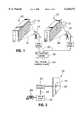
- FIG. 1is a diagrammatic and part isometric view showing installation of a telecommunications system directed to closely adjacent buildings;
- FIG. 2to a larger scale than FIG. 1, is a sectional view through part of a wall of the building showing diagrammatically part of the system of the embodiment extending into an individual room;
- FIG. 3to a larger scale than FIG. 2, is a cross-sectional view through a patch antenna used in the system of the first embodiment
- FIG. 4is a view in the direction of arrow IV in FIG. 3 of the patch antenna
- FIG. 5is an isometric cross-sectional view of the patch antenna of FIGS. 3 and 4;
- FIG. 6is a diagrammatic isometric view on the inside of a window to a room and showing part of a second embodiment
- FIG. 7is a horizontal cross-sectional view of a building and employing a specific arrangement of the first embodiment
- FIG. 8is a plan view of closely adjacent buildings incorporating telecommunications systems according to either of the first and second embodiments;
- FIG. 9is a plan view of two adjacent buildings showing the use of the telecommunications system of either of the two embodiments.
- FIG. 10is a cross-sectional view taken along line X--X in FIG. 9 to show the construction of a communications system employed in one of the buildings in FIG. 8.
- each building 10is large and is either a commercial building or is an apartment building as indicated by the large facial areas of the buildings.
- Each buildingis multi-storey with a large number of rooms or apartments and each window 12 at the side of each building as shown, is associated perhaps with a separate room or apartment.
- the installation of a telecommunications service at this stagemay almost be impossible because of virtually insurmountable problems apart from which it would be a particularly labor intensive, time consuming, and expensive operation.
- the inventionenables the provision of a telecommunications system under these circumstances while minimizing the cost of the operation together with the almost total lack of disruption of the buildings themselves.
- an external radio signal transmitting and receiving antenna 14is positioned so as to direct a divergent beam of radio signals towards a predetermined wall surface area of the building. As shown, this predetermined wall surface area is substantially the total wall surface area of the building facing the antenna.
- Each antenna 14is of a known type which is adjustable to provide a desirably shaped divergent beam pattern to enable the required beam illumination of the building surface which it faces so that the beam 16 is of the desired pattern as shown for instance in FIG. 1.
- Each of the antenna 14is connected to a wireless access controller 18 forming part of a public switched telephone network 20 by means of individual telecommunications cables 22.
- the radio signals from either of the antenna 14should not be absorbed entirely through the building associated with the particular antenna so that any possibility of radio signals in one beam interfering with those in another is minimized.
- the power output of each of the antennas 14is extremely minimal and with the antenna positioned possibly in the region of up to 100 ft away from their individual buildings, then the power output need only be of the order of 10 dBm.
- each of the antenna 14directs a divergent beam 16 of radio signals towards the facing wall of its individual building 10 with a minimization in the amount that the divergent beam extends outwardly beyond edges of the building profile.
- Each apartment or room in each building 10is equipped, as required, with one or more terminals which may include a data processing terminal or a telephone as required.
- each room that requires a telecommunications service and is equipped with a terminalhas a transmission and receiving antenna mounted in a suitable position for receiving signals from the associated antenna 14.
- the room antennamay be of any required structure suitable for the purpose, in this particular embodiment the room antenna is a patch antenna 26 which is secured by an adhesive (not shown) to a window 12 on the inside of the room.
- a patch antenna 26 as shown in FIGS. 3, 4 and 5,is of planar configuration and comprises a planar radio signal transmitting and receiving patch 28 adhesively secured to one side of a planar plexi-glass substrate 30.
- the patch 28is rectangular (see FIG. 4).
- a planar ground plane 32has a main portion 34a which is mounted upon the other side of the substrate 30. This ground plane extends from the main portion around edges of the plexi-glass substrate and extends outwardly beyond the patch 28 to form a rectangular metal collar 34.
- the collar 34is formed by a peripheral wall of the ground member, the peripheral wall having a first leg 34b of a U-shape extending outwardly through and beyond the plane of the patch, and a base 34c of the U-shape which extends inwards of the panel a short distance to terminate in a second leg 34d of the U-shape which is spaced from the first leg and extends to the substrate 30.
- the second leg 34dis spaced from the patch to enable an edge strip 34e, surrounding the patch while lying in the same plane, the extend towards the patch from the second leg 34d while terminating short of the patch.
- the U-shape forming the collar 34is occupied by an extension 29 of the substrate 30, the extension separating the legs 34b and 34d.
- a plurality of elongate electrically conducting members in the form of pins 31electrically connect the edge strip 34d around a marginal edge portion thereof, to the main portion of the ground member by passing through the substrate 30.
- the patch 28is coupled through an aperture 36 in the ground plane to a transmission line 38 which extends across the width of the ground plane.
- This transmission line 38acts as a conventional electrical transmission wire which is connected to an RF/voice converter 40 (FIG. 2).
- the converterin turn is connected by a telecommunications wire 42 to a terminal outlet 44 to which the telephone is connected.
- radio signalsare transmitted as a divergent beam 16 from each of the antenna 14 towards each of the associated patch antenna 26.
- the signalselectively operates an individual telephone or is received by an individual data terminal through the appropriate patch antenna and RF/voice converter 40. Messages returned from the terminal are passed from the appropriate patch antenna 26 to the associated antenna 14 for transmission in the opposite direction.
- the particular patch antenna described in the embodimentis itself unique.
- the use of the metal collar 34 provided by the ground planerestricts the size of the ground plane below that which would otherwise be required if the ground plane were to be entirely of planar configuration.
- the use of the collaralso ensures that although the ground plane size is minimized this is done without any appreciable degradation in the antenna's performance.
- the raised collaralso ensures that the gain of the antenna reduces at a exceedingly slow rate as the observer moves away from its bore sight. This is particularly important as it means that for most buildings, the same design of patch antenna may be used in each room facing outwardly from the side surface of the building for operation with the same antenna 14.
- the height of the collar 34affects, advantageously, the operational beam width of the patch panel antenna.
- the operational beam widthis also affected by the distance provided between the leg 34c of the peripheral wall and the pins 37.
- a resonant cavityis provided within the boundary formed by the pins 37 thereby also increasing the beam width.
- This cavityalso includes the window glass of a window 12 to which the patch antenna 26 is fitted.
- the pins 37further assist in reducing the antenna size for required performance and renders the antenna less sensitive to reception interference.
- the layer of plexi-glass 30is replaced by the window glass itself.
- the receiving and transmitting patch 28 and the metal collar 34may be adhered to the outside surface of the window and the ground plane with associated components would be adhered onto the inside surface of the window while maintaining its positional relationship to the patch 28 in the manner shown in FIG. 3.
- a lower lossmay be achieved with this structure than that found in the first embodiment as the radio signal would propagate through the window glass.
- an inhabitant of any particular building supplied with a telecommunications system according to the inventionmay communicate by telephone with any other person living in that particular building or he may communicate with any other telephone that can be reached through the public switched telephone network.
- a second embodiment as shown in FIG. 6the employment of an outside antenna for directing a divergent beam of radio signals at a building wall is as described in the first embodiment.
- telecommunications serviceis to be made to a wireless telephone 50 for use in a particular apartment or room.
- the window 12 associated with that roomhas one patch antenna 26 mounted upon the window by the main portion of the ground member being adhesively secured to the glass.
- a second patch antenna 26ais provided upon and adhered to the inside surface of the window glass. Signal amplification is provided between the two patch antennas.
- the patch antenna 26atransmits radio signals to the radio telephone 50, the user therefore having the freedom to move in unrestricted fashion throughout the room or apartment while making telephonic use.
- the first embodimentmay be utilized with the employment of an outside antenna 14 on each side of the building.
- This arrangementis suitable when a high rise building 52 has a central corridor on each floor with a plurality of apartments or rooms on each side of the corridor. With this arrangement, the power signal from each antenna 14 need be sufficient only for being received by the patch antennas 26 on the facing side of the building.
- inside telephones 24are provided whereas in others, data processing units 58 are present and are in communication with corresponding patch panels 26.
- FIGS. 8 and 9show alternative arrangements for using telecommunications systems according to the invention and possibly as described in the first and second embodiments.
- each main building surface 62is faced by an outside antenna 14 which projects the radio signals as described above towards that building surface.
- the beam 16 of radio signalsmay not be intended to project from any particular antenna 14 outwardly beyond the other side of its associated building, the fact that the beam may extend outwardly beyond edges of the building may be sufficient reason for interference with signals in that beam with signals in another beam.
- antennas 14which may cause signal interference to be operating in different frequency bands.
- the lower antenna 14 as shown by the Figuremay be transmitting on a different frequency band from either of the two antennas 14 next above it and supplying signals to the other two buildings 62.
- an antenna 14provides a divergent beam 16 of radio signals sufficient to supply a telecommunications service to two buildings 64 and 66 which are close to each other, but with the building 64 having one end facing generally in the direction of the antenna 14.
- telecommunications servicemay be transmitted to each room in that building by providing two antennas 26 and 26a (similar to that shown in FIG. 5) upon an end window 65 of the building disposed at an end of a central corridor on each floor.
- the antenna 26acommunicates by radio signals with further antenna 66 positioned appropriately along the length of the corridor at various positions, each antenna 66 serving an appropriate room or apartment.
- the antenna 66may project outwardly from a corridor wall so as to be in the "line of sight" of the antenna 26a.
- Each of the antennas 66is connected by cable with a terminal through a wall into the associated room or apartment.
Landscapes
- Radio Relay Systems (AREA)
- Support Of Aerials (AREA)
- Transceivers (AREA)
Abstract
Description
Claims (30)
Priority Applications (1)
| Application Number | Priority Date | Filing Date | Title |
|---|---|---|---|
| US08/667,951US6128471A (en) | 1995-08-21 | 1996-06-19 | Telecommunication method and system for communicating with multiple terminals in a building through multiple antennas |
Applications Claiming Priority (2)
| Application Number | Priority Date | Filing Date | Title |
|---|---|---|---|
| US257095P | 1995-08-21 | 1995-08-21 | |
| US08/667,951US6128471A (en) | 1995-08-21 | 1996-06-19 | Telecommunication method and system for communicating with multiple terminals in a building through multiple antennas |
Publications (1)
| Publication Number | Publication Date |
|---|---|
| US6128471Atrue US6128471A (en) | 2000-10-03 |
Family
ID=21701395
Family Applications (1)
| Application Number | Title | Priority Date | Filing Date |
|---|---|---|---|
| US08/667,951Expired - LifetimeUS6128471A (en) | 1995-08-21 | 1996-06-19 | Telecommunication method and system for communicating with multiple terminals in a building through multiple antennas |
Country Status (2)
| Country | Link |
|---|---|
| US (1) | US6128471A (en) |
| CA (1) | CA2180925C (en) |
Cited By (41)
| Publication number | Priority date | Publication date | Assignee | Title |
|---|---|---|---|---|
| WO2001052447A3 (en)* | 2000-01-14 | 2002-05-02 | Andrew Corp | Repeaters for wireless communication systems |
| US20020177401A1 (en)* | 2001-05-22 | 2002-11-28 | Judd Mano D. | Repeater for customer premises |
| US20030179092A1 (en)* | 2000-03-03 | 2003-09-25 | Loftus Stephen Clive | Returnable item for use in storage and transportation of commercial goods |
| US6731904B1 (en) | 1999-07-20 | 2004-05-04 | Andrew Corporation | Side-to-side repeater |
| US20040166802A1 (en)* | 2003-02-26 | 2004-08-26 | Ems Technologies, Inc. | Cellular signal enhancer |
| US6934511B1 (en) | 1999-07-20 | 2005-08-23 | Andrew Corporation | Integrated repeater |
| US6987487B2 (en) | 2001-02-19 | 2006-01-17 | Andrew Corporation | Antenna system |
| US20060205343A1 (en)* | 2005-03-11 | 2006-09-14 | Runyon Donald L | Wireless repeater with feedback suppression features |
| US20070080864A1 (en)* | 2005-10-11 | 2007-04-12 | M/A-Com, Inc. | Broadband proximity-coupled cavity backed patch antenna |
| US20070126638A1 (en)* | 2005-12-02 | 2007-06-07 | M/A-Com, Inc. | Compact broadband patch antenna |
| US7274688B2 (en) | 2000-04-18 | 2007-09-25 | Serconet Ltd. | Telephone communication system over a single telephone line |
| US20070232228A1 (en)* | 2006-04-04 | 2007-10-04 | Mckay David L Sr | Wireless repeater with universal server base unit and modular donor antenna options |
| US7436842B2 (en) | 2001-10-11 | 2008-10-14 | Serconet Ltd. | Outlet with analog signal adapter, a method for use thereof and a network using said outlet |
| US7522714B2 (en) | 2000-03-20 | 2009-04-21 | Serconet Ltd. | Telephone outlet for implementing a local area network over telephone lines and a local area network using such outlets |
| US7542554B2 (en) | 2001-07-05 | 2009-06-02 | Serconet, Ltd | Telephone outlet with packet telephony adapter, and a network using same |
| US7557675B2 (en) | 2005-03-22 | 2009-07-07 | Radiacion Y Microondas, S.A. | Broad band mechanical phase shifter |
| US7656904B2 (en) | 2003-03-13 | 2010-02-02 | Mosaid Technologies Incorporated | Telephone system having multiple distinct sources and accessories therefor |
| US7873058B2 (en) | 2004-11-08 | 2011-01-18 | Mosaid Technologies Incorporated | Outlet with analog signal adapter, a method for use thereof and a network using said outlet |
| US8325636B2 (en) | 1998-07-28 | 2012-12-04 | Mosaid Technologies Incorporated | Local area network of serial intelligent cells |
| US9748656B2 (en) | 2013-12-13 | 2017-08-29 | Harris Corporation | Broadband patch antenna and associated methods |
| US9867052B2 (en) | 2000-03-27 | 2018-01-09 | Commscope Technologies Llc | Multiprotocol antenna system for multiple service providers |
| US20190319335A1 (en)* | 2014-11-25 | 2019-10-17 | View, Inc. | Window antennas |
| US10499269B2 (en) | 2015-11-12 | 2019-12-03 | Commscope Technologies Llc | Systems and methods for assigning controlled nodes to channel interfaces of a controller |
| US10498434B2 (en) | 2000-07-19 | 2019-12-03 | CommScope Technolgies LLC | Point-to-multipoint digital radio frequency transport |
| US10986164B2 (en) | 2004-01-13 | 2021-04-20 | May Patents Ltd. | Information device |
| US11054711B2 (en) | 2014-11-25 | 2021-07-06 | View, Inc. | Electromagnetic-shielding electrochromic windows |
| US11114742B2 (en) | 2014-11-25 | 2021-09-07 | View, Inc. | Window antennas |
| US11205926B2 (en) | 2009-12-22 | 2021-12-21 | View, Inc. | Window antennas for emitting radio frequency signals |
| US11342791B2 (en) | 2009-12-22 | 2022-05-24 | View, Inc. | Wirelessly powered and powering electrochromic windows |
| USRE49377E1 (en) | 2002-12-03 | 2023-01-17 | Commscope Technologies Llc | Distributed digital antenna system |
| US11579571B2 (en) | 2014-03-05 | 2023-02-14 | View, Inc. | Monitoring sites containing switchable optical devices and controllers |
| US11630366B2 (en) | 2009-12-22 | 2023-04-18 | View, Inc. | Window antennas for emitting radio frequency signals |
| US11631493B2 (en) | 2020-05-27 | 2023-04-18 | View Operating Corporation | Systems and methods for managing building wellness |
| US11732527B2 (en) | 2009-12-22 | 2023-08-22 | View, Inc. | Wirelessly powered and powering electrochromic windows |
| US11740529B2 (en) | 2015-10-06 | 2023-08-29 | View, Inc. | Controllers for optically-switchable devices |
| US11750594B2 (en) | 2020-03-26 | 2023-09-05 | View, Inc. | Access and messaging in a multi client network |
| US11796885B2 (en) | 2012-04-17 | 2023-10-24 | View, Inc. | Controller for optically-switchable windows |
| US12087997B2 (en) | 2019-05-09 | 2024-09-10 | View, Inc. | Antenna systems for controlled coverage in buildings |
| US12176596B2 (en) | 2019-05-31 | 2024-12-24 | View, Inc. | Building antenna |
| US12212976B2 (en) | 2021-06-02 | 2025-01-28 | Skyworks Solutions, Inc. | Antenna arrangement for distributing millimeter wave cellular service over a face of a building |
| US12235560B2 (en) | 2014-11-25 | 2025-02-25 | View, Inc. | Faster switching electrochromic devices |
Families Citing this family (1)
| Publication number | Priority date | Publication date | Assignee | Title |
|---|---|---|---|---|
| IL137078A (en)* | 1999-07-20 | 2005-05-17 | Andrew Corp | Side-to-side repeater and adaptive cancellation for repeater |
Citations (3)
| Publication number | Priority date | Publication date | Assignee | Title |
|---|---|---|---|---|
| US5594937A (en)* | 1994-09-02 | 1997-01-14 | Ghz Equipment Company | System for the transmission and reception of directional radio signals utilizing a gigahertz implosion concept |
| US5828964A (en)* | 1994-12-08 | 1998-10-27 | Bell Atlantic Science & Technology Inc | Apparatus and method for point-to-point multipoint radio transmission |
| US5918183A (en)* | 1992-09-01 | 1999-06-29 | Trimble Navigation Limited | Concealed mobile communications system |
- 1996
- 1996-06-19USUS08/667,951patent/US6128471A/ennot_activeExpired - Lifetime
- 1996-07-10CACA002180925Apatent/CA2180925C/ennot_activeExpired - Fee Related
Patent Citations (3)
| Publication number | Priority date | Publication date | Assignee | Title |
|---|---|---|---|---|
| US5918183A (en)* | 1992-09-01 | 1999-06-29 | Trimble Navigation Limited | Concealed mobile communications system |
| US5594937A (en)* | 1994-09-02 | 1997-01-14 | Ghz Equipment Company | System for the transmission and reception of directional radio signals utilizing a gigahertz implosion concept |
| US5828964A (en)* | 1994-12-08 | 1998-10-27 | Bell Atlantic Science & Technology Inc | Apparatus and method for point-to-point multipoint radio transmission |
Cited By (90)
| Publication number | Priority date | Publication date | Assignee | Title |
|---|---|---|---|---|
| US8908673B2 (en) | 1998-07-28 | 2014-12-09 | Conversant Intellectual Property Management Incorporated | Local area network of serial intelligent cells |
| US8325636B2 (en) | 1998-07-28 | 2012-12-04 | Mosaid Technologies Incorporated | Local area network of serial intelligent cells |
| US8867523B2 (en) | 1998-07-28 | 2014-10-21 | Conversant Intellectual Property Management Incorporated | Local area network of serial intelligent cells |
| US8885659B2 (en) | 1998-07-28 | 2014-11-11 | Conversant Intellectual Property Management Incorporated | Local area network of serial intelligent cells |
| US8885660B2 (en) | 1998-07-28 | 2014-11-11 | Conversant Intellectual Property Management Incorporated | Local area network of serial intelligent cells |
| US6934511B1 (en) | 1999-07-20 | 2005-08-23 | Andrew Corporation | Integrated repeater |
| US8630581B2 (en) | 1999-07-20 | 2014-01-14 | Andrew Llc | Repeaters for wireless communication systems |
| US8010042B2 (en) | 1999-07-20 | 2011-08-30 | Andrew Llc | Repeaters for wireless communication systems |
| US6731904B1 (en) | 1999-07-20 | 2004-05-04 | Andrew Corporation | Side-to-side repeater |
| US8358970B2 (en) | 1999-07-20 | 2013-01-22 | Andrew Corporation | Repeaters for wireless communication systems |
| US6745003B1 (en)* | 1999-07-20 | 2004-06-01 | Andrew Corporation | Adaptive cancellation for wireless repeaters |
| US8971796B2 (en) | 1999-07-20 | 2015-03-03 | Andrew Llc | Repeaters for wireless communication systems |
| US20040110469A1 (en)* | 2000-01-14 | 2004-06-10 | Judd Mano D. | Repeaters for wireless communication systems |
| US7577398B2 (en) | 2000-01-14 | 2009-08-18 | Andrew Llc | Repeaters for wireless communication systems |
| WO2001052447A3 (en)* | 2000-01-14 | 2002-05-02 | Andrew Corp | Repeaters for wireless communication systems |
| US20030179092A1 (en)* | 2000-03-03 | 2003-09-25 | Loftus Stephen Clive | Returnable item for use in storage and transportation of commercial goods |
| US6844857B2 (en)* | 2000-03-03 | 2005-01-18 | Linpac Mouldings Limited | Returnable item for use in storage and transportation of commercial goods |
| US7522714B2 (en) | 2000-03-20 | 2009-04-21 | Serconet Ltd. | Telephone outlet for implementing a local area network over telephone lines and a local area network using such outlets |
| US8855277B2 (en) | 2000-03-20 | 2014-10-07 | Conversant Intellectual Property Managment Incorporated | Telephone outlet for implementing a local area network over telephone lines and a local area network using such outlets |
| US7715534B2 (en) | 2000-03-20 | 2010-05-11 | Mosaid Technologies Incorporated | Telephone outlet for implementing a local area network over telephone lines and a local area network using such outlets |
| US8363797B2 (en) | 2000-03-20 | 2013-01-29 | Mosaid Technologies Incorporated | Telephone outlet for implementing a local area network over telephone lines and a local area network using such outlets |
| US10321328B2 (en) | 2000-03-27 | 2019-06-11 | Commscope Technologies Llc | Multiprotocol antenna system for multiple service providers |
| US9867052B2 (en) | 2000-03-27 | 2018-01-09 | Commscope Technologies Llc | Multiprotocol antenna system for multiple service providers |
| US8559422B2 (en) | 2000-04-18 | 2013-10-15 | Mosaid Technologies Incorporated | Telephone communication system over a single telephone line |
| US7397791B2 (en) | 2000-04-18 | 2008-07-08 | Serconet, Ltd. | Telephone communication system over a single telephone line |
| US7274688B2 (en) | 2000-04-18 | 2007-09-25 | Serconet Ltd. | Telephone communication system over a single telephone line |
| US7593394B2 (en) | 2000-04-18 | 2009-09-22 | Mosaid Technologies Incorporated | Telephone communication system over a single telephone line |
| US8223800B2 (en) | 2000-04-18 | 2012-07-17 | Mosaid Technologies Incorporated | Telephone communication system over a single telephone line |
| US7466722B2 (en) | 2000-04-18 | 2008-12-16 | Serconet Ltd | Telephone communication system over a single telephone line |
| US8000349B2 (en) | 2000-04-18 | 2011-08-16 | Mosaid Technologies Incorporated | Telephone communication system over a single telephone line |
| US10498434B2 (en) | 2000-07-19 | 2019-12-03 | CommScope Technolgies LLC | Point-to-multipoint digital radio frequency transport |
| US10505635B2 (en) | 2000-07-19 | 2019-12-10 | Commscope Technologies Llc | Point-to-multipoint digital radio frequency transport |
| US6987487B2 (en) | 2001-02-19 | 2006-01-17 | Andrew Corporation | Antenna system |
| US7027770B2 (en)* | 2001-05-22 | 2006-04-11 | Andrew Corporation | Repeater for customer premises |
| US20020177401A1 (en)* | 2001-05-22 | 2002-11-28 | Judd Mano D. | Repeater for customer premises |
| WO2002095866A1 (en)* | 2001-05-22 | 2002-11-28 | Andrew Corporation | Repeater for radio signals |
| US7542554B2 (en) | 2001-07-05 | 2009-06-02 | Serconet, Ltd | Telephone outlet with packet telephony adapter, and a network using same |
| US8761186B2 (en) | 2001-07-05 | 2014-06-24 | Conversant Intellectual Property Management Incorporated | Telephone outlet with packet telephony adapter, and a network using same |
| US7680255B2 (en) | 2001-07-05 | 2010-03-16 | Mosaid Technologies Incorporated | Telephone outlet with packet telephony adaptor, and a network using same |
| US8472593B2 (en) | 2001-07-05 | 2013-06-25 | Mosaid Technologies Incorporated | Telephone outlet with packet telephony adaptor, and a network using same |
| US7769030B2 (en) | 2001-07-05 | 2010-08-03 | Mosaid Technologies Incorporated | Telephone outlet with packet telephony adapter, and a network using same |
| US7889720B2 (en) | 2001-10-11 | 2011-02-15 | Mosaid Technologies Incorporated | Outlet with analog signal adapter, a method for use thereof and a network using said outlet |
| US7860084B2 (en) | 2001-10-11 | 2010-12-28 | Mosaid Technologies Incorporated | Outlet with analog signal adapter, a method for use thereof and a network using said outlet |
| US7436842B2 (en) | 2001-10-11 | 2008-10-14 | Serconet Ltd. | Outlet with analog signal adapter, a method for use thereof and a network using said outlet |
| US7453895B2 (en) | 2001-10-11 | 2008-11-18 | Serconet Ltd | Outlet with analog signal adapter, a method for use thereof and a network using said outlet |
| US7953071B2 (en) | 2001-10-11 | 2011-05-31 | Mosaid Technologies Incorporated | Outlet with analog signal adapter, a method for use thereof and a network using said outlet |
| USRE49377E1 (en) | 2002-12-03 | 2023-01-17 | Commscope Technologies Llc | Distributed digital antenna system |
| USRE50112E1 (en) | 2002-12-03 | 2024-09-03 | Outdoor Wireless Networks LLC | Distributed digital antenna system |
| US20040166802A1 (en)* | 2003-02-26 | 2004-08-26 | Ems Technologies, Inc. | Cellular signal enhancer |
| US7656904B2 (en) | 2003-03-13 | 2010-02-02 | Mosaid Technologies Incorporated | Telephone system having multiple distinct sources and accessories therefor |
| US7738453B2 (en) | 2003-03-13 | 2010-06-15 | Mosaid Technologies Incorporated | Telephone system having multiple sources and accessories therefor |
| US7746905B2 (en) | 2003-03-13 | 2010-06-29 | Mosaid Technologies Incorporated | Private telephone network connected to more than one public network |
| US8238328B2 (en) | 2003-03-13 | 2012-08-07 | Mosaid Technologies Incorporated | Telephone system having multiple distinct sources and accessories therefor |
| US11095708B2 (en) | 2004-01-13 | 2021-08-17 | May Patents Ltd. | Information device |
| US10986165B2 (en) | 2004-01-13 | 2021-04-20 | May Patents Ltd. | Information device |
| US10986164B2 (en) | 2004-01-13 | 2021-04-20 | May Patents Ltd. | Information device |
| US7873058B2 (en) | 2004-11-08 | 2011-01-18 | Mosaid Technologies Incorporated | Outlet with analog signal adapter, a method for use thereof and a network using said outlet |
| US20060205343A1 (en)* | 2005-03-11 | 2006-09-14 | Runyon Donald L | Wireless repeater with feedback suppression features |
| US7557675B2 (en) | 2005-03-22 | 2009-07-07 | Radiacion Y Microondas, S.A. | Broad band mechanical phase shifter |
| US20070080864A1 (en)* | 2005-10-11 | 2007-04-12 | M/A-Com, Inc. | Broadband proximity-coupled cavity backed patch antenna |
| US7636063B2 (en) | 2005-12-02 | 2009-12-22 | Eswarappa Channabasappa | Compact broadband patch antenna |
| US20070126638A1 (en)* | 2005-12-02 | 2007-06-07 | M/A-Com, Inc. | Compact broadband patch antenna |
| US20070232228A1 (en)* | 2006-04-04 | 2007-10-04 | Mckay David L Sr | Wireless repeater with universal server base unit and modular donor antenna options |
| US11342791B2 (en) | 2009-12-22 | 2022-05-24 | View, Inc. | Wirelessly powered and powering electrochromic windows |
| US11732527B2 (en) | 2009-12-22 | 2023-08-22 | View, Inc. | Wirelessly powered and powering electrochromic windows |
| US11630366B2 (en) | 2009-12-22 | 2023-04-18 | View, Inc. | Window antennas for emitting radio frequency signals |
| US11205926B2 (en) | 2009-12-22 | 2021-12-21 | View, Inc. | Window antennas for emitting radio frequency signals |
| US11796885B2 (en) | 2012-04-17 | 2023-10-24 | View, Inc. | Controller for optically-switchable windows |
| US9748656B2 (en) | 2013-12-13 | 2017-08-29 | Harris Corporation | Broadband patch antenna and associated methods |
| US11579571B2 (en) | 2014-03-05 | 2023-02-14 | View, Inc. | Monitoring sites containing switchable optical devices and controllers |
| US12155110B2 (en) | 2014-11-25 | 2024-11-26 | View, Inc. | Window antennas |
| US20190319335A1 (en)* | 2014-11-25 | 2019-10-17 | View, Inc. | Window antennas |
| US11114742B2 (en) | 2014-11-25 | 2021-09-07 | View, Inc. | Window antennas |
| US12278419B2 (en) | 2014-11-25 | 2025-04-15 | View Operating Corporation | Window antennas |
| US11054711B2 (en) | 2014-11-25 | 2021-07-06 | View, Inc. | Electromagnetic-shielding electrochromic windows |
| US12235560B2 (en) | 2014-11-25 | 2025-02-25 | View, Inc. | Faster switching electrochromic devices |
| US11670833B2 (en) | 2014-11-25 | 2023-06-06 | View, Inc. | Window antennas |
| US10797373B2 (en)* | 2014-11-25 | 2020-10-06 | View, Inc. | Window antennas |
| CN113889744A (en)* | 2014-11-25 | 2022-01-04 | 唯景公司 | window antenna |
| US11462814B2 (en) | 2014-11-25 | 2022-10-04 | View, Inc. | Window antennas |
| US11799187B2 (en) | 2014-11-25 | 2023-10-24 | View, Inc. | Window antennas |
| US10673121B2 (en) | 2014-11-25 | 2020-06-02 | View, Inc. | Window antennas |
| US11740529B2 (en) | 2015-10-06 | 2023-08-29 | View, Inc. | Controllers for optically-switchable devices |
| US10499269B2 (en) | 2015-11-12 | 2019-12-03 | Commscope Technologies Llc | Systems and methods for assigning controlled nodes to channel interfaces of a controller |
| US12087997B2 (en) | 2019-05-09 | 2024-09-10 | View, Inc. | Antenna systems for controlled coverage in buildings |
| US12176596B2 (en) | 2019-05-31 | 2024-12-24 | View, Inc. | Building antenna |
| US11882111B2 (en) | 2020-03-26 | 2024-01-23 | View, Inc. | Access and messaging in a multi client network |
| US11750594B2 (en) | 2020-03-26 | 2023-09-05 | View, Inc. | Access and messaging in a multi client network |
| US11631493B2 (en) | 2020-05-27 | 2023-04-18 | View Operating Corporation | Systems and methods for managing building wellness |
| US12212976B2 (en) | 2021-06-02 | 2025-01-28 | Skyworks Solutions, Inc. | Antenna arrangement for distributing millimeter wave cellular service over a face of a building |
Also Published As
| Publication number | Publication date |
|---|---|
| CA2180925C (en) | 2003-08-26 |
| MX9603550A (en) | 1997-07-31 |
| CA2180925A1 (en) | 1997-02-22 |
Similar Documents
| Publication | Publication Date | Title |
|---|---|---|
| US6128471A (en) | Telecommunication method and system for communicating with multiple terminals in a building through multiple antennas | |
| US7027770B2 (en) | Repeater for customer premises | |
| US6222503B1 (en) | System and method of integrating and concealing antennas, antenna subsystems and communications subsystems | |
| JP3347986B2 (en) | repeater | |
| US6963305B2 (en) | Electromagnetic coupler system | |
| US6563465B2 (en) | Ceiling tile antenna and method for constructing same | |
| US6801753B1 (en) | Method and device at a transmitter and receiver unit in a mobile telephone system | |
| JP2002204240A (en) | Radio lan system and waveguide device for radio lan system | |
| EP0630070A1 (en) | Leaky antenna for personal communications system | |
| KR100727076B1 (en) | Signal Distribution System and Method | |
| US8798529B2 (en) | Method and apparatus for enhancing wireless communications to and from the inside of a building | |
| JP3813082B2 (en) | Radio wave supply system using leaky cables laid vertically | |
| MXPA96003550A (en) | Telecommunications system and telecommunicac method | |
| JPH08125600A (en) | Radio wave communication system inside building | |
| CN1097359C (en) | Telecommunication system and method of elecommunication | |
| JPS63138840A (en) | cordless telephone | |
| JPH0474025A (en) | Radio wave repeater | |
| HK1017184B (en) | Telecommunication system and method of telecommunication | |
| HK1017184A1 (en) | Telecommunication system and method of telecommunication | |
| KR100719467B1 (en) | Outdoor relay system | |
| JP2792300B2 (en) | Information transmission method in buildings | |
| KR100719474B1 (en) | Outdoor relay system and oscillation control method | |
| JPH07154850A (en) | Mobile phone indoor service system | |
| JP3372151B2 (en) | Transmission / reception function expansion device for mobile phones | |
| JPH1065668A (en) | Radio lan system |
Legal Events
| Date | Code | Title | Description |
|---|---|---|---|
| AS | Assignment | Owner name:NORTHERN TELECOM LIMITED, CANADA Free format text:ASSIGNMENT OF ASSIGNORS INTEREST;ASSIGNORS:QUELCH, PETER J.;LITVA, JOHN;QI, YIHONG;AND OTHERS;REEL/FRAME:008092/0592;SIGNING DATES FROM 19960516 TO 19960528 | |
| AS | Assignment | Owner name:NORTEL NETWORKS CORPORATION, CANADA Free format text:CHANGE OF NAME;ASSIGNOR:NORTHERN TELECOM LIMITED;REEL/FRAME:010567/0001 Effective date:19990429 | |
| AS | Assignment | Owner name:NORTEL NETWORKS LIMITED, CANADA Free format text:CHANGE OF NAME;ASSIGNOR:NORTEL NETWORKS CORPORATION;REEL/FRAME:011195/0706 Effective date:20000830 Owner name:NORTEL NETWORKS LIMITED,CANADA Free format text:CHANGE OF NAME;ASSIGNOR:NORTEL NETWORKS CORPORATION;REEL/FRAME:011195/0706 Effective date:20000830 | |
| STCF | Information on status: patent grant | Free format text:PATENTED CASE | |
| FEPP | Fee payment procedure | Free format text:PAYOR NUMBER ASSIGNED (ORIGINAL EVENT CODE: ASPN); ENTITY STATUS OF PATENT OWNER: LARGE ENTITY | |
| FPAY | Fee payment | Year of fee payment:4 | |
| FPAY | Fee payment | Year of fee payment:8 | |
| AS | Assignment | Owner name:ROCKSTAR BIDCO, LP, NEW YORK Free format text:ASSIGNMENT OF ASSIGNORS INTEREST;ASSIGNOR:NORTEL NETWORKS LIMITED;REEL/FRAME:027164/0356 Effective date:20110729 | |
| FPAY | Fee payment | Year of fee payment:12 | |
| AS | Assignment | Owner name:ROCKSTAR CONSORTIUM US LP, TEXAS Free format text:ASSIGNMENT OF ASSIGNORS INTEREST;ASSIGNOR:ROCKSTAR BIDCO, LP;REEL/FRAME:032099/0853 Effective date:20120509 | |
| AS | Assignment | Owner name:CONSTELLATION TECHNOLOGIES LLC, TEXAS Free format text:ASSIGNMENT OF ASSIGNORS INTEREST;ASSIGNOR:ROCKSTAR CONSORTIUM US LP;REEL/FRAME:032162/0524 Effective date:20131113 | |
| AS | Assignment | Owner name:RPX CLEARINGHOUSE LLC, CALIFORNIA Free format text:ASSIGNMENT OF ASSIGNORS INTEREST;ASSIGNORS:ROCKSTAR CONSORTIUM US LP;ROCKSTAR CONSORTIUM LLC;BOCKSTAR TECHNOLOGIES LLC;AND OTHERS;REEL/FRAME:034924/0779 Effective date:20150128 | |
| AS | Assignment | Owner name:JPMORGAN CHASE BANK, N.A., AS COLLATERAL AGENT, IL Free format text:SECURITY AGREEMENT;ASSIGNORS:RPX CORPORATION;RPX CLEARINGHOUSE LLC;REEL/FRAME:038041/0001 Effective date:20160226 | |
| AS | Assignment | Owner name:RPX CLEARINGHOUSE LLC, CALIFORNIA Free format text:RELEASE (REEL 038041 / FRAME 0001);ASSIGNOR:JPMORGAN CHASE BANK, N.A.;REEL/FRAME:044970/0030 Effective date:20171222 Owner name:RPX CORPORATION, CALIFORNIA Free format text:RELEASE (REEL 038041 / FRAME 0001);ASSIGNOR:JPMORGAN CHASE BANK, N.A.;REEL/FRAME:044970/0030 Effective date:20171222 |