US6128183A - Attachment structure for a display device and an equipment in which such structure is provided - Google Patents
Attachment structure for a display device and an equipment in which such structure is providedDownload PDFInfo
- Publication number
- US6128183A US6128183AUS09/022,908US2290898AUS6128183AUS 6128183 AUS6128183 AUS 6128183AUS 2290898 AUS2290898 AUS 2290898AUS 6128183 AUS6128183 AUS 6128183A
- Authority
- US
- United States
- Prior art keywords
- edge
- pin
- aperture
- display device
- attachment structure
- Prior art date
- Legal status (The legal status is an assumption and is not a legal conclusion. Google has not performed a legal analysis and makes no representation as to the accuracy of the status listed.)
- Expired - Lifetime
Links
Images


Classifications
- G—PHYSICS
- G06—COMPUTING OR CALCULATING; COUNTING
- G06F—ELECTRIC DIGITAL DATA PROCESSING
- G06F1/00—Details not covered by groups G06F3/00 - G06F13/00 and G06F21/00
- G06F1/16—Constructional details or arrangements
- G06F1/1613—Constructional details or arrangements for portable computers
- G06F1/1633—Constructional details or arrangements of portable computers not specific to the type of enclosures covered by groups G06F1/1615 - G06F1/1626
- G06F1/1637—Details related to the display arrangement, including those related to the mounting of the display in the housing
- G—PHYSICS
- G06—COMPUTING OR CALCULATING; COUNTING
- G06F—ELECTRIC DIGITAL DATA PROCESSING
- G06F1/00—Details not covered by groups G06F3/00 - G06F13/00 and G06F21/00
- G06F1/16—Constructional details or arrangements
- G06F1/1613—Constructional details or arrangements for portable computers
- G06F1/1615—Constructional details or arrangements for portable computers with several enclosures having relative motions, each enclosure supporting at least one I/O or computing function
- G06F1/1616—Constructional details or arrangements for portable computers with several enclosures having relative motions, each enclosure supporting at least one I/O or computing function with folding flat displays, e.g. laptop computers or notebooks having a clamshell configuration, with body parts pivoting to an open position around an axis parallel to the plane they define in closed position
- Y—GENERAL TAGGING OF NEW TECHNOLOGICAL DEVELOPMENTS; GENERAL TAGGING OF CROSS-SECTIONAL TECHNOLOGIES SPANNING OVER SEVERAL SECTIONS OF THE IPC; TECHNICAL SUBJECTS COVERED BY FORMER USPC CROSS-REFERENCE ART COLLECTIONS [XRACs] AND DIGESTS
- Y10—TECHNICAL SUBJECTS COVERED BY FORMER USPC
- Y10S—TECHNICAL SUBJECTS COVERED BY FORMER USPC CROSS-REFERENCE ART COLLECTIONS [XRACs] AND DIGESTS
- Y10S248/00—Supports
- Y10S248/917—Video display screen support
- Y10S248/919—Adjustably orientable video screen support
- Y—GENERAL TAGGING OF NEW TECHNOLOGICAL DEVELOPMENTS; GENERAL TAGGING OF CROSS-SECTIONAL TECHNOLOGIES SPANNING OVER SEVERAL SECTIONS OF THE IPC; TECHNICAL SUBJECTS COVERED BY FORMER USPC CROSS-REFERENCE ART COLLECTIONS [XRACs] AND DIGESTS
- Y10—TECHNICAL SUBJECTS COVERED BY FORMER USPC
- Y10S—TECHNICAL SUBJECTS COVERED BY FORMER USPC CROSS-REFERENCE ART COLLECTIONS [XRACs] AND DIGESTS
- Y10S345/00—Computer graphics processing and selective visual display systems
- Y10S345/905—Display device with housing structure
Definitions
- This inventionrelates to an attachment structure of a display device and an equipment in which such structure is provided and, particularly, to an attachment structure to attach a display device such as a liquid crystal panel in a small portable electronic equipment to the housing of such equipment, and an equipment in which such structure is provided.
- a liquid crystal panel used to be attached to the external casingby having a tab or a flange T extrude in parallel to the plane of the liquid crystal panel near the 4 corners of the periphery of a bezel B which comprises an outer frame of a rectangular shaped liquid crystal panel and tightening the tab T with a screw S against the fixing nut N located on the inner bottom of the external casing C in the direction orthogonal to the plane of the liquid crystal panel P.
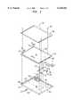
- FIG. 1is a perspective view of an embodiment of this invention in a disassembled form.
- FIG. 2is an enlarged cross sectional view of a portion of an embodiment of the attachment structure of this invention.
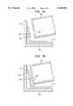
- FIGS. 3(A)-3(C)is a cross sectional view to illustrate the attachment procedure of an embodiment of the attachment structure of this invention.
- FIGS. 4(A)-4(C)is a cross sectional view to illustrate the attachment procedure of another embodiment of the attachment structure of this invention.
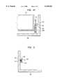
- FIG. 5is a cross sectional view of another embodiment of the attachment structure of this invention.
- FIG. 6is a cross sectional view of another embodiment of the attachment structure of this invention.
- FIG. 7is a cross sectional view of a still further embodiment of the attachment structure of this invention.
- FIG. 8is a cross sectional view of a still further embodiment of the attachment structure of this invention.
- FIG. 9is a cross sectional view of a still further embodiment of the attachment structure of this invention.
- FIG. 10is a perspective view of an attachment structure of a prior art in a disassembled form.
- an attachment structure for a display devicefor attaching a display device which comprises a display part of a shape of a rectangular plate and a frame part arranged in the outer periphery thereof to an external casing having a rectangular opening part formed of a side wall, in which an aperture is formed in at least one of two opposing edges of the frame in the direction parallel to the plane of the display part and the external casing is provided with a pin which is engageable with the aperture.
- Another aspect of this inventionis an attachment structure for a display device for attaching a display device which comprises a display part of a shape of a rectangular plate and a frame part arranged in the outer periphery thereof to an external casing having a rectangular opening part formed of a side wall, in which an aperture is formed in at least one of two opposing edges of the frame in the direction parallel to the plane of the display part and the external casing is provided with a pin which is actuated in the direction parallel to the plane of the display part and engageable with the aperture.
- the pinmay be provided up right on the second edge of L shaped resilient member the first edge of which is fixed on the bottom wall of the external casing, the second edge being parallel to the side wall.
- the pinmay be supported by a supporting member fixed on the side wall of the external casing so as to be movable in the direction parallel to the plane of the display part and is activated by a spring which is interposed between the side wall and the pin.
- a guide slopeis formed in at least either one of the frame and the pin for retracting the pin when the display device is inserted into the opening part.
- a taperis formed in the direction of insertion in at least either one of the aperture and the pin.
- the other edge of the framemay be fixed by an arbitrary means after engaging the pin with the aperture in the one edge with the display device tilted when it is inserted into the opening of the external casing.
- the other edge of the framemay be fixed by an arbitrary means after engaging the pin with the aperture in the one edge while retracting the pin when the display device is inserted into the opening of the external casing.
- FIG. 1a perspective view of a disassembled cover part of a so called notebook personal computer is shown as an example of an equipment to which this invention is applied.
- the cover partessentially comprises a liquid crystal panel 102 which is a display part of a shape of a rectangular plate, a liquid crystal module 100 provided with a bezel 104 which is a frame arranged in the periphery of the panel, a rear cover 200 which is a portion of an external casing to which the liquid crystal module 100 is attached and a front bezel 300 which is also a portion of the external casing attached to the outer periphery of the liquid crystal module 100.
- the front bezel 300is overlaid on the periphery of the liquid crystal module 100 and attached to the rear cover 200 with a screw 302 after the liquid after the liquid crystal module 100 is attached to the rear cover 200 as described later.
- two apertures 106are formed on one of two opposing edges of the bezel 104 which is a frame of the liquid crystal module 100 in the direction parallel to the plane of the liquid crystal panel 102 while in the other of the edges are formed a tab 108 protruding in the direction parallel to the plane of the liquid crystal panel 102 as well as two apertures 110 in the direction orthogonal to the plane of liquid crystal panel 102 similarly to the prior art structure.
- the rear cover 200has a rectangular opening 204 which is defined by 4 side walls 202 thereof.
- Two fixing nuts 208are fixedly attached to the bottom wall 206 at a position corresponding to the above described aperture 110.
- 210is a bracket having a planar view substantially in L shape which is fixedly attached to the bottom wall of the rear cover 200 with a screw 212 with the end of the arms bent in right angle into L shape. That is, defining the portion of the arm fixed to the bottom wall 206 of the rear cover 200 as being the first edge 214, the second edge 216 which is in right angle thereto is positioned in parallel to the side wall 202.
- a pin 218 which is engageable with the aperture 106is provided up right on the second edge 216 of the bracket 210 which includes the L shaped portion of the member (hidden in FIG. 1, refer to FIG. 2).
- the pin 218may be either provided directly inside the side wall 202 of the rear cover 200 or the bracket 210 including the L shaped portion of the member may be made of a material of high rigidity.
- the liquid crystal module 100is fixedly attached to the rear cover 200 by engaging the pin 218 with the aperture 106 (FIG. 3(B)) while tilting the liquid crystal module 100 so that the edge having the aperture 106 formed therein comes downside as shown in FIG. 3(A) and then inserting the screw 112 in the aperture 110 and tightening the tab 108 on the other edge of the liquid crystal module 100 against the fixing nut 208.
- the pin 218with the aperture 106
- FIG. 3(B)the aperture 106
- the screw 112 in the aperture 110and tightening the tab 108 on the other edge of the liquid crystal module 100 against the fixing nut 208.
- bracket 210comprising the L shaped portion of the member of the same structure is made of a resilient material such as stainless steel and the pin 218 is movable in the direction parallel to the plane of the liquid crystal panel 102 (strictly saying, substantially parallel because the second edge 216 in right angle to the first edge 214 is bent actually, the first edge 214 being the portion of the arm which is fixed to the bottom wall 206 of the rear cover 200).
- the liquid crystal module 100may be tilted so that the edge having the aperture 106 formed in the liquid crystal module 100 comes downside as shown in FIG. 4(A) but this is not necessarily required and, instead, the liquid crystal module 100 is fixed to the rear cover 200 by inserting the liquid crystal module 100 into the opening part 204 of the rear cover 200 while retracting the pin 218 and engage the pin 218 with the aperture 106 (FIG. 4(B)) and then, like the preceding mode of practice, inserting the screw 112 in the aperture 110 of the tab 108 on the other edge of the liquid crystal module 100 and tightening it to the fixing nut 208.
- a pin 218 having a stopper 218A at the rear endmay be movably supported in the direction parallel to the plane of the liquid crystal panel 102 by a bracket 220 which is a supporting member fixedly provided on the side wall 202 of the rear cover 200 as shown in FIG. 5 so that it is actuated by a spring 222 which is interposed between the side wall 202 and the stopper 218A of the pin 218.
- either one of the bezel 104 and the pin 218may be formed with a guide slope for retracting the pin 218 when the liquid crystal module 100 is inserted into the opening part 204 as shown in FIGS. 6 and 7.
- a guide slope 104Cis formed along the lower edge of the bezel 104 while, in the mode shown in FIG. 7, the guide slope 218C is formed at the tip of the pin 218. Both of them may be formed in combination.
- the liquid crystal module 100may be simply inserted because the pin 218 is subject to a force component which makes it retracted after the pin 218 contacts the guide slope 104C or 218C even when the liquid crystal module 100 is inserted without being tilted in inserting it to the opening part 204.
- either one of the aperture of the bezel 104 and the pin 218may be formed with a taper thinning toward the direction of insertion of the pin 218 as shown in FIGS. 8 and 9.
- the pin 218is formed with a taper 218T thinning toward the tip of the pin while, in the mode shown in FIG. 9, the aperture 106 is formed with a taper 106T thinning in the direction of insertion of the pin 218.
- the pin 218By forming the taper 218T or 106T in this way, the pin 218 easily engages with the aperture 106 in inserting the liquid crystal module into the opening part 204 and any loose engagement is removed because the pin 218 is resiliently actuated after engagement resulting in a rigid attachment.
- the gap between the outer periphery of the bezel 104 and the side wall 202 of the rear cover 200had to be at least larger than the diameter of the screw head (e.g., 4 mm or 5.5 mm) so that a gap of more than about 5 mm was required in one side and about 10 mm for both sides while the outer dimension was reduced by about 3 mm for one side and as much as 6 mm for both sides according to the above embodiment.
- the diameter of the screw heade.g., 4 mm or 5.5 mm
Landscapes
- Engineering & Computer Science (AREA)
- Computer Hardware Design (AREA)
- Theoretical Computer Science (AREA)
- Physics & Mathematics (AREA)
- Human Computer Interaction (AREA)
- General Engineering & Computer Science (AREA)
- General Physics & Mathematics (AREA)
- Mathematical Physics (AREA)
- Devices For Indicating Variable Information By Combining Individual Elements (AREA)
Abstract
Description
Claims (10)
Priority Applications (1)
| Application Number | Priority Date | Filing Date | Title |
|---|---|---|---|
| US09/627,556US6339530B1 (en) | 1997-05-09 | 2000-07-28 | Attachment structure for attaching a display device to and reducing an external size of a housing of equipment in which the attachment structure is provided |
Applications Claiming Priority (2)
| Application Number | Priority Date | Filing Date | Title |
|---|---|---|---|
| JP9119510AJPH10319864A (en) | 1997-05-09 | 1997-05-09 | Mounting structure for display device and equipment provided with the same |
| JP9-119510 | 1997-09-05 |
Related Child Applications (1)
| Application Number | Title | Priority Date | Filing Date |
|---|---|---|---|
| US09/627,556DivisionUS6339530B1 (en) | 1997-05-09 | 2000-07-28 | Attachment structure for attaching a display device to and reducing an external size of a housing of equipment in which the attachment structure is provided |
Publications (1)
| Publication Number | Publication Date |
|---|---|
| US6128183Atrue US6128183A (en) | 2000-10-03 |
Family
ID=14763059
Family Applications (2)
| Application Number | Title | Priority Date | Filing Date |
|---|---|---|---|
| US09/022,908Expired - LifetimeUS6128183A (en) | 1997-05-09 | 1998-02-12 | Attachment structure for a display device and an equipment in which such structure is provided |
| US09/627,556Expired - Fee RelatedUS6339530B1 (en) | 1997-05-09 | 2000-07-28 | Attachment structure for attaching a display device to and reducing an external size of a housing of equipment in which the attachment structure is provided |
Family Applications After (1)
| Application Number | Title | Priority Date | Filing Date |
|---|---|---|---|
| US09/627,556Expired - Fee RelatedUS6339530B1 (en) | 1997-05-09 | 2000-07-28 | Attachment structure for attaching a display device to and reducing an external size of a housing of equipment in which the attachment structure is provided |
Country Status (2)
| Country | Link |
|---|---|
| US (2) | US6128183A (en) |
| JP (1) | JPH10319864A (en) |
Cited By (26)
| Publication number | Priority date | Publication date | Assignee | Title |
|---|---|---|---|---|
| US6304432B1 (en)* | 1997-05-24 | 2001-10-16 | Lg.Philips Lcd. Od., Ltd | Method of mounting liquid crystal display module and apparatus thereof |
| US6330148B1 (en)* | 1999-01-13 | 2001-12-11 | Lg. Philips Lcd Co., Ltd. | Flat panel display module for computer |
| US6339530B1 (en)* | 1997-05-09 | 2002-01-15 | International Business Machines Corporation | Attachment structure for attaching a display device to and reducing an external size of a housing of equipment in which the attachment structure is provided |
| US6392723B1 (en)* | 1999-06-29 | 2002-05-21 | Kabushiki Kaisha Toshiba | Flat display device with substantially rectangular bezel |
| US6406151B1 (en)* | 1999-02-02 | 2002-06-18 | Seiko Epson Corporation | Electro-optical device mounting unit and projector using the same |
| US6421231B1 (en)* | 1999-03-13 | 2002-07-16 | Samsung Electronics Co., Ltd. | Display unit and portable computer using the same |
| US6456343B2 (en)* | 2000-07-20 | 2002-09-24 | L.G. Philips Lcd Co., Ltd. | Liquid crystal display |
| US6460998B1 (en)* | 1999-03-08 | 2002-10-08 | Seiko Epson Corporation | Adjustment mechanism and projector employing the same |
| US6467858B1 (en)* | 1999-12-23 | 2002-10-22 | Gateway, Inc. | Computer component retention tray |
| US20020154476A1 (en)* | 1998-11-11 | 2002-10-24 | Cho Young Woo | Portable computer and method for mounting a flat panel display device module |
| US20020159227A1 (en)* | 2001-04-27 | 2002-10-31 | Katsumaru Sasaki | Display device having housing fitted with display panel and electronic apparatus having the display device |
| US6538709B1 (en)* | 1998-02-17 | 2003-03-25 | International Business Machines Corporation | LCD panel including plurality of display panel parts wrapped around by a thin plastic film envelope with an opening |
| US20030122995A1 (en)* | 2001-12-29 | 2003-07-03 | Lg.Philips Lcd Co., Ltd. | Liquid crystal display system and method of fabricating the same |
| US20040120104A1 (en)* | 2002-12-24 | 2004-06-24 | Jeong Ki Ryoung | Liquid crystal display device |
| US6768636B2 (en)* | 2000-04-26 | 2004-07-27 | Advanced Display Inc. | Display device |
| US20040184224A1 (en)* | 2001-07-10 | 2004-09-23 | Fujitsu Limited | Plane unit structure |
| US20040192445A1 (en)* | 2002-11-18 | 2004-09-30 | Kazuki Emori | Gaming machine |
| US20040240165A1 (en)* | 2003-01-31 | 2004-12-02 | Kabushiki Kaisha Toshiba | Display device and electronic apparatus provided with the same |
| US6879308B2 (en)* | 2000-11-01 | 2005-04-12 | Au Optronics Corp. | Housing for flat panel displays and method for receiving flat panel displays |
| US20050168930A1 (en)* | 1998-10-23 | 2005-08-04 | Kim Jong H. | Portable computer and method for mounting a flat panel display device thereon |
| US20060208145A1 (en)* | 2004-12-07 | 2006-09-21 | Asustek Computer Inc. | Electronic apparatus |
| US20100315769A1 (en)* | 2009-06-11 | 2010-12-16 | Mathew Dinesh C | Portable computers with spring-mounted displays |
| US20120013533A1 (en)* | 2010-07-15 | 2012-01-19 | Tpk Touch Solutions Inc | Keyboard, electronic device using the same and input method |
| US20120075784A1 (en)* | 2010-06-29 | 2012-03-29 | Compal Electronics, Inc. | Display device |
| TWI409571B (en)* | 2004-07-29 | 2013-09-21 | Moxtek Inc | Housing for mounting beam splitter and spatial light modulator and housing device for an optical component |
| US9119295B2 (en) | 2011-10-11 | 2015-08-25 | Rockwell Automation Technologies, Inc. | Display mounting techniques |
Families Citing this family (10)
| Publication number | Priority date | Publication date | Assignee | Title |
|---|---|---|---|---|
| US6654078B1 (en) | 1999-02-18 | 2003-11-25 | Nec Lcd Technologies, Ltd. | Liquid crystal module mounting structure and mobile terminal mounted with the same |
| KR100806806B1 (en)* | 2001-05-29 | 2008-02-22 | 엘지.필립스 엘시디 주식회사 | Combined device of flat panel display |
| KR100793729B1 (en)* | 2001-09-27 | 2008-01-10 | 삼성전자주식회사 | LCD Display |
| EP1895386A1 (en)* | 2006-08-31 | 2008-03-05 | TCL Thomson Electronics Europe SAS | A flat screen assembly |
| JP4645626B2 (en)* | 2007-07-04 | 2011-03-09 | 船井電機株式会社 | Thin display device |
| CN101518404A (en)* | 2008-02-29 | 2009-09-02 | 鹏智科技(深圳)有限公司 | Digital photo frame and outer frame thereof |
| JP5040979B2 (en)* | 2009-09-29 | 2012-10-03 | 株式会社デンソーウェーブ | Electric equipment display device mounting structure |
| CN102891976B (en)* | 2012-09-24 | 2015-07-22 | 深圳市华星光电技术有限公司 | Display |
| CN102866521A (en)* | 2012-10-17 | 2013-01-09 | 深圳市华星光电技术有限公司 | Narrow-frame liquid crystal display device |
| CN103857233A (en)* | 2012-12-07 | 2014-06-11 | 富泰华工业(深圳)有限公司 | Shell |
Citations (15)
| Publication number | Priority date | Publication date | Assignee | Title |
|---|---|---|---|---|
| JPS59104180A (en)* | 1982-12-06 | 1984-06-15 | Clarion Co Ltd | variable capacitance diode |
| JPS6184587A (en)* | 1984-10-02 | 1986-04-30 | 株式会社東芝 | nuclear fusion device |
| US5268816A (en)* | 1982-09-28 | 1993-12-07 | Lexmark International, Inc. | Movable display screen for a computer |
| US5422751A (en)* | 1992-10-14 | 1995-06-06 | Apple Computer, Inc. | Liquid crystal display assembly employing front bezel, frame holding liquid crystal cell attached to bezel, and light source and back plate attached to bezel |
| JPH07181899A (en)* | 1993-12-24 | 1995-07-21 | Rohm Co Ltd | Structure for mounting panel display device |
| JPH085998A (en)* | 1994-06-21 | 1996-01-12 | Fujitsu Ltd | Display device |
| JPH0863287A (en)* | 1994-08-22 | 1996-03-08 | Alps Electric Co Ltd | Display device with touch panel and its assembling method |
| US5559670A (en)* | 1994-10-18 | 1996-09-24 | International Business Machines Corporation | Convertible display computer |
| US5568357A (en)* | 1994-06-15 | 1996-10-22 | Metanetics Corporation | Display support having cradled damping caps for floating core shock absorption |
| US5570267A (en)* | 1995-07-12 | 1996-10-29 | Ma; Hsi-Kuang | Flat display module |
| US5583529A (en)* | 1989-10-31 | 1996-12-10 | Kabushiki Kaisha Toshiba | Portable apparatus having a flat panel type display unit |
| US5629833A (en)* | 1994-08-22 | 1997-05-13 | Casio Computer Co., Ltd. | Panel unit swing mechanism having first and second guide grooves and first and second connecting members |
| US5640216A (en)* | 1994-04-13 | 1997-06-17 | Hitachi, Ltd. | Liquid crystal display device having video signal driving circuit mounted on one side and housing |
| US5805125A (en)* | 1991-07-17 | 1998-09-08 | Hitachi, Ltd. | Portable information processing apparatus and liquid crystal display device |
| US5905550A (en)* | 1996-05-09 | 1999-05-18 | Kabushiki Kaisha Toshiba | Display device having a casing containing a display panel, and portable apparatus having the display device |
Family Cites Families (9)
| Publication number | Priority date | Publication date | Assignee | Title |
|---|---|---|---|---|
| JPH0455083A (en) | 1990-06-25 | 1992-02-21 | Toshiba Corp | Laser light scanner device |
| JPH0621018A (en) | 1992-06-29 | 1994-01-28 | Sony Corp | Dry etching method |
| US6061231A (en)* | 1993-09-01 | 2000-05-09 | Ncr Corporation | Computer display assembly |
| JPH08190085A (en) | 1995-01-09 | 1996-07-23 | Citizen Watch Co Ltd | Liquid crystal display device |
| JP3504024B2 (en) | 1995-05-29 | 2004-03-08 | 株式会社東芝 | Liquid crystal display |
| US5640296A (en)* | 1995-09-27 | 1997-06-17 | Dynapro Systems, Inc. | Touch screen enclosure having a universal rear enclosure unit, a touch screen plate, and first and second seals |
| JPH09114391A (en) | 1995-10-20 | 1997-05-02 | Fujitsu Ltd | Display device |
| JPH10319864A (en)* | 1997-05-09 | 1998-12-04 | Internatl Business Mach Corp <Ibm> | Mounting structure for display device and equipment provided with the same |
| JP3461269B2 (en)* | 1997-09-04 | 2003-10-27 | インターナショナル・ビジネス・マシーンズ・コーポレーション | Display device assembly and information processing equipment |
- 1997
- 1997-05-09JPJP9119510Apatent/JPH10319864A/enactivePending
- 1998
- 1998-02-12USUS09/022,908patent/US6128183A/ennot_activeExpired - Lifetime
- 2000
- 2000-07-28USUS09/627,556patent/US6339530B1/ennot_activeExpired - Fee Related
Patent Citations (15)
| Publication number | Priority date | Publication date | Assignee | Title |
|---|---|---|---|---|
| US5268816A (en)* | 1982-09-28 | 1993-12-07 | Lexmark International, Inc. | Movable display screen for a computer |
| JPS59104180A (en)* | 1982-12-06 | 1984-06-15 | Clarion Co Ltd | variable capacitance diode |
| JPS6184587A (en)* | 1984-10-02 | 1986-04-30 | 株式会社東芝 | nuclear fusion device |
| US5583529A (en)* | 1989-10-31 | 1996-12-10 | Kabushiki Kaisha Toshiba | Portable apparatus having a flat panel type display unit |
| US5805125A (en)* | 1991-07-17 | 1998-09-08 | Hitachi, Ltd. | Portable information processing apparatus and liquid crystal display device |
| US5422751A (en)* | 1992-10-14 | 1995-06-06 | Apple Computer, Inc. | Liquid crystal display assembly employing front bezel, frame holding liquid crystal cell attached to bezel, and light source and back plate attached to bezel |
| JPH07181899A (en)* | 1993-12-24 | 1995-07-21 | Rohm Co Ltd | Structure for mounting panel display device |
| US5640216A (en)* | 1994-04-13 | 1997-06-17 | Hitachi, Ltd. | Liquid crystal display device having video signal driving circuit mounted on one side and housing |
| US5568357A (en)* | 1994-06-15 | 1996-10-22 | Metanetics Corporation | Display support having cradled damping caps for floating core shock absorption |
| JPH085998A (en)* | 1994-06-21 | 1996-01-12 | Fujitsu Ltd | Display device |
| JPH0863287A (en)* | 1994-08-22 | 1996-03-08 | Alps Electric Co Ltd | Display device with touch panel and its assembling method |
| US5629833A (en)* | 1994-08-22 | 1997-05-13 | Casio Computer Co., Ltd. | Panel unit swing mechanism having first and second guide grooves and first and second connecting members |
| US5559670A (en)* | 1994-10-18 | 1996-09-24 | International Business Machines Corporation | Convertible display computer |
| US5570267A (en)* | 1995-07-12 | 1996-10-29 | Ma; Hsi-Kuang | Flat display module |
| US5905550A (en)* | 1996-05-09 | 1999-05-18 | Kabushiki Kaisha Toshiba | Display device having a casing containing a display panel, and portable apparatus having the display device |
Cited By (53)
| Publication number | Priority date | Publication date | Assignee | Title |
|---|---|---|---|---|
| US6339530B1 (en)* | 1997-05-09 | 2002-01-15 | International Business Machines Corporation | Attachment structure for attaching a display device to and reducing an external size of a housing of equipment in which the attachment structure is provided |
| US7193842B2 (en) | 1997-05-24 | 2007-03-20 | L.G.Phillips Lcd Co., Ltd. | Method of mounting liquid crystal display module and apparatus thereof |
| US6304432B1 (en)* | 1997-05-24 | 2001-10-16 | Lg.Philips Lcd. Od., Ltd | Method of mounting liquid crystal display module and apparatus thereof |
| US7511949B2 (en) | 1997-05-24 | 2009-03-31 | Lg Display Co., Ltd. | Method of mounting liquid crystal display module and apparatus thereof |
| US20070133159A1 (en)* | 1997-05-24 | 2007-06-14 | Kim Yong G | Method of mounting liquid crystal display module and apparatus thereof |
| US20040085274A1 (en)* | 1997-05-24 | 2004-05-06 | Kim Yong Gyu | Method of mounting liquid crystal display module and apparatus thereof |
| US6538709B1 (en)* | 1998-02-17 | 2003-03-25 | International Business Machines Corporation | LCD panel including plurality of display panel parts wrapped around by a thin plastic film envelope with an opening |
| US7907399B2 (en)* | 1998-10-23 | 2011-03-15 | Lg Display Co., Ltd. | Portable computer and method for mounting a flat panel display device thereon |
| US7885059B2 (en) | 1998-10-23 | 2011-02-08 | Lg Display Co., Ltd. | Portable computer and method for mounting a flat panel display device thereon |
| US7864138B2 (en) | 1998-10-23 | 2011-01-04 | Lg Display Co., Ltd. | Portable computer and method for mounting a flat panel display device thereon |
| US7828616B2 (en) | 1998-10-23 | 2010-11-09 | Lg Display Co., Ltd. | Method of forming a portable computer having a flat panel display device |
| US20050195560A1 (en)* | 1998-10-23 | 2005-09-08 | Kim Jong H. | Portable computer and method for mounting a flat panel display device thereon |
| US20050168930A1 (en)* | 1998-10-23 | 2005-08-04 | Kim Jong H. | Portable computer and method for mounting a flat panel display device thereon |
| US7663871B2 (en)* | 1998-11-11 | 2010-02-16 | Lg Display Co., Ltd. | Portable computer and method for mounting a flat panel display device module |
| US20060171106A1 (en)* | 1998-11-11 | 2006-08-03 | Cho Young W | Portable computer and method for mounting a flat panel display device module |
| US20020154476A1 (en)* | 1998-11-11 | 2002-10-24 | Cho Young Woo | Portable computer and method for mounting a flat panel display device module |
| US7170741B2 (en) | 1998-11-11 | 2007-01-30 | Lg. Philips Lcd Co., Ltd. | Portable computer and method for mounting a flat panel display device module |
| US6330148B1 (en)* | 1999-01-13 | 2001-12-11 | Lg. Philips Lcd Co., Ltd. | Flat panel display module for computer |
| US6565216B2 (en) | 1999-02-02 | 2003-05-20 | Seiko Epson Corporation | Electro-optical device mounting unit and projection display device using the same |
| US6406151B1 (en)* | 1999-02-02 | 2002-06-18 | Seiko Epson Corporation | Electro-optical device mounting unit and projector using the same |
| US6460998B1 (en)* | 1999-03-08 | 2002-10-08 | Seiko Epson Corporation | Adjustment mechanism and projector employing the same |
| US6829110B2 (en) | 1999-03-08 | 2004-12-07 | Seiko Epson Corporation | Adjustment mechanism and projector employing the same |
| US6421231B1 (en)* | 1999-03-13 | 2002-07-16 | Samsung Electronics Co., Ltd. | Display unit and portable computer using the same |
| US6392723B1 (en)* | 1999-06-29 | 2002-05-21 | Kabushiki Kaisha Toshiba | Flat display device with substantially rectangular bezel |
| US6467858B1 (en)* | 1999-12-23 | 2002-10-22 | Gateway, Inc. | Computer component retention tray |
| US6768636B2 (en)* | 2000-04-26 | 2004-07-27 | Advanced Display Inc. | Display device |
| US6456343B2 (en)* | 2000-07-20 | 2002-09-24 | L.G. Philips Lcd Co., Ltd. | Liquid crystal display |
| US20020191125A1 (en)* | 2000-07-20 | 2002-12-19 | Young-Su Kim | Method of fixing LCD to a supporter |
| US6816211B2 (en)* | 2000-07-20 | 2004-11-09 | Lg. Philips Lcd Co., Ltd. | Method of fixing LCD to a supporter |
| US6879308B2 (en)* | 2000-11-01 | 2005-04-12 | Au Optronics Corp. | Housing for flat panel displays and method for receiving flat panel displays |
| US20020159227A1 (en)* | 2001-04-27 | 2002-10-31 | Katsumaru Sasaki | Display device having housing fitted with display panel and electronic apparatus having the display device |
| US6989986B2 (en)* | 2001-07-10 | 2006-01-24 | Fujitsu Limited | Plane unit structure |
| US20040184224A1 (en)* | 2001-07-10 | 2004-09-23 | Fujitsu Limited | Plane unit structure |
| US20030122995A1 (en)* | 2001-12-29 | 2003-07-03 | Lg.Philips Lcd Co., Ltd. | Liquid crystal display system and method of fabricating the same |
| US6876409B2 (en)* | 2001-12-29 | 2005-04-05 | Lg.Philips Lcd Co., Ltd. | Liquid crystal display system and method of fabricating the same |
| US7479066B2 (en)* | 2002-11-18 | 2009-01-20 | Aruze Corp. | Gaming machine |
| US20040192445A1 (en)* | 2002-11-18 | 2004-09-30 | Kazuki Emori | Gaming machine |
| US20060227499A1 (en)* | 2002-12-24 | 2006-10-12 | Jeong Ki R | Liquid crystal display device |
| CN100462779C (en)* | 2002-12-24 | 2009-02-18 | 乐金显示有限公司 | display device |
| US7274560B2 (en) | 2002-12-24 | 2007-09-25 | Lg.Philips Lcd Co., Ltd. | Liquid crystal display device |
| US20040120104A1 (en)* | 2002-12-24 | 2004-06-24 | Jeong Ki Ryoung | Liquid crystal display device |
| CN1976565B (en)* | 2002-12-24 | 2010-05-19 | 乐金显示有限公司 | Liquid crystal display device |
| US7075783B2 (en)* | 2002-12-24 | 2006-07-11 | Lg.Philips Lcd Co., Ltd. | Liquid crystal display device |
| US6992884B2 (en)* | 2003-01-31 | 2006-01-31 | Kabushiki Kaisha Toshiba | Display device and electronic apparatus provided with the same |
| US20040240165A1 (en)* | 2003-01-31 | 2004-12-02 | Kabushiki Kaisha Toshiba | Display device and electronic apparatus provided with the same |
| TWI409571B (en)* | 2004-07-29 | 2013-09-21 | Moxtek Inc | Housing for mounting beam splitter and spatial light modulator and housing device for an optical component |
| US20060208145A1 (en)* | 2004-12-07 | 2006-09-21 | Asustek Computer Inc. | Electronic apparatus |
| US20100315769A1 (en)* | 2009-06-11 | 2010-12-16 | Mathew Dinesh C | Portable computers with spring-mounted displays |
| US8199477B2 (en)* | 2009-06-11 | 2012-06-12 | Apple Inc. | Portable computers with spring-mounted displays |
| US20120075784A1 (en)* | 2010-06-29 | 2012-03-29 | Compal Electronics, Inc. | Display device |
| US20120013533A1 (en)* | 2010-07-15 | 2012-01-19 | Tpk Touch Solutions Inc | Keyboard, electronic device using the same and input method |
| US9507522B2 (en)* | 2010-07-15 | 2016-11-29 | Tpk Touch Solutions Inc. | Virtual keyboard, electronic device using the same and input method |
| US9119295B2 (en) | 2011-10-11 | 2015-08-25 | Rockwell Automation Technologies, Inc. | Display mounting techniques |
Also Published As
| Publication number | Publication date |
|---|---|
| US6339530B1 (en) | 2002-01-15 |
| JPH10319864A (en) | 1998-12-04 |
Similar Documents
| Publication | Publication Date | Title |
|---|---|---|
| US6128183A (en) | Attachment structure for a display device and an equipment in which such structure is provided | |
| US6525790B1 (en) | Liquid crystal module mounting structure | |
| EP1150199B1 (en) | Display device and information terminal apparatus | |
| US6411501B1 (en) | Portable computer and method for mounting a flat display device module | |
| KR100487435B1 (en) | liquid crystal display device module having a mounting frame combination structure | |
| KR100806806B1 (en) | Combined device of flat panel display | |
| US7508655B2 (en) | Display device | |
| US20110116217A1 (en) | Image display device | |
| KR20040015796A (en) | Flat unit structure | |
| US7808574B2 (en) | Liquid crystal display device having integral receiving box and assembly method for same | |
| JP2001013889A (en) | Flat panel display | |
| JP2000206900A (en) | Flat panel display device for computer and its module | |
| US6618240B1 (en) | Computer having a flat panel display | |
| GB2407121A (en) | Glass fixing grommet | |
| JP2000258756A (en) | LCD module | |
| US9223338B2 (en) | Display device | |
| EP2497993B1 (en) | Cabinet structure assembly | |
| CN113325631A (en) | Back plate, backlight module and liquid crystal display device | |
| JP2004258678A (en) | Display device | |
| KR20030046305A (en) | Display device | |
| KR100524486B1 (en) | LCD module and display device using same | |
| JP2002072914A (en) | Flat panel display | |
| KR100319201B1 (en) | Liquid crystal display device | |
| KR100579551B1 (en) | Computer with Flat Panel Display | |
| JP2001067012A (en) | Display module and its installation structure |
Legal Events
| Date | Code | Title | Description |
|---|---|---|---|
| AS | Assignment | Owner name:INTERNATIONAL BUSINESS MACHINES CORPORATION, NEW Y Free format text:ASSIGNMENT OF ASSIGNORS INTEREST;ASSIGNORS:UCHIYAMA, YOSHIHARU;KURIHARA, MIKIO;NOGUCHI, HIROYUKI;REEL/FRAME:009095/0111 Effective date:19980128 | |
| FEPP | Fee payment procedure | Free format text:PAYOR NUMBER ASSIGNED (ORIGINAL EVENT CODE: ASPN); ENTITY STATUS OF PATENT OWNER: LARGE ENTITY | |
| CC | Certificate of correction | ||
| FEPP | Fee payment procedure | Free format text:PAYOR NUMBER ASSIGNED (ORIGINAL EVENT CODE: ASPN); ENTITY STATUS OF PATENT OWNER: LARGE ENTITY Free format text:PAYER NUMBER DE-ASSIGNED (ORIGINAL EVENT CODE: RMPN); ENTITY STATUS OF PATENT OWNER: LARGE ENTITY | |
| FPAY | Fee payment | Year of fee payment:4 | |
| AS | Assignment | Owner name:LENOVO (SINGAPORE) PTE LTD.,SINGAPORE Free format text:ASSIGNMENT OF ASSIGNORS INTEREST;ASSIGNOR:INTERNATIONAL BUSINESS MACHINES CORPORATION;REEL/FRAME:016891/0507 Effective date:20050520 Owner name:LENOVO (SINGAPORE) PTE LTD., SINGAPORE Free format text:ASSIGNMENT OF ASSIGNORS INTEREST;ASSIGNOR:INTERNATIONAL BUSINESS MACHINES CORPORATION;REEL/FRAME:016891/0507 Effective date:20050520 | |
| REMI | Maintenance fee reminder mailed | ||
| REIN | Reinstatement after maintenance fee payment confirmed | ||
| FP | Lapsed due to failure to pay maintenance fee | Effective date:20081003 | |
| FEPP | Fee payment procedure | Free format text:PETITION RELATED TO MAINTENANCE FEES FILED (ORIGINAL EVENT CODE: PMFP); ENTITY STATUS OF PATENT OWNER: LARGE ENTITY | |
| FEPP | Fee payment procedure | Free format text:PETITION RELATED TO MAINTENANCE FEES GRANTED (ORIGINAL EVENT CODE: PMFG); ENTITY STATUS OF PATENT OWNER: LARGE ENTITY | |
| FEPP | Fee payment procedure | Free format text:PAYOR NUMBER ASSIGNED (ORIGINAL EVENT CODE: ASPN); ENTITY STATUS OF PATENT OWNER: LARGE ENTITY Free format text:PAYER NUMBER DE-ASSIGNED (ORIGINAL EVENT CODE: RMPN); ENTITY STATUS OF PATENT OWNER: LARGE ENTITY | |
| FPAY | Fee payment | Year of fee payment:8 | |
| SULP | Surcharge for late payment | ||
| PRDP | Patent reinstated due to the acceptance of a late maintenance fee | Effective date:20090212 | |
| STCF | Information on status: patent grant | Free format text:PATENTED CASE | |
| FPAY | Fee payment | Year of fee payment:12 | |
| AS | Assignment | Owner name:LENOVO PC INTERNATIONAL, HONG KONG Free format text:NUNC PRO TUNC ASSIGNMENT;ASSIGNOR:LENOVO (SINGAPORE) PTE LTD.;REEL/FRAME:037160/0001 Effective date:20130401 |