US6127811A - Micro-electromechanical system and voltage shifter, method of synchronizing an electronic system and a micromechanical system of a micro-electromechanical system - Google Patents
Micro-electromechanical system and voltage shifter, method of synchronizing an electronic system and a micromechanical system of a micro-electromechanical systemDownload PDFInfo
- Publication number
- US6127811A US6127811AUS09/228,707US22870799AUS6127811AUS 6127811 AUS6127811 AUS 6127811AUS 22870799 AUS22870799 AUS 22870799AUS 6127811 AUS6127811 AUS 6127811A
- Authority
- US
- United States
- Prior art keywords
- electrical
- micro
- capacitor
- product signal
- micromechanical
- Prior art date
- Legal status (The legal status is an assumption and is not a legal conclusion. Google has not performed a legal analysis and makes no representation as to the accuracy of the status listed.)
- Expired - Lifetime
Links
- 238000000034methodMethods0.000titleclaimsabstractdescription32
- 239000003990capacitorSubstances0.000claimsabstractdescription90
- 238000005070samplingMethods0.000claimsabstractdescription16
- 230000008878couplingEffects0.000claimsabstractdescription9
- 238000010168coupling processMethods0.000claimsabstractdescription9
- 238000005859coupling reactionMethods0.000claimsabstractdescription9
- 238000001914filtrationMethods0.000claimsdescription3
- 230000036962time dependentEffects0.000description10
- 238000010586diagramMethods0.000description6
- 230000001360synchronised effectEffects0.000description6
- XUIMIQQOPSSXEZ-UHFFFAOYSA-NSiliconChemical compound[Si]XUIMIQQOPSSXEZ-UHFFFAOYSA-N0.000description5
- 229910052710siliconInorganic materials0.000description5
- 239000010703siliconSubstances0.000description5
- 238000004519manufacturing processMethods0.000description3
- 239000004065semiconductorSubstances0.000description3
- 235000012431wafersNutrition0.000description3
- VYPSYNLAJGMNEJ-UHFFFAOYSA-NSilicium dioxideChemical compoundO=[Si]=OVYPSYNLAJGMNEJ-UHFFFAOYSA-N0.000description2
- 230000001133accelerationEffects0.000description2
- 238000007599dischargingMethods0.000description2
- 238000005516engineering processMethods0.000description2
- 239000012530fluidSubstances0.000description2
- 229910021420polycrystalline siliconInorganic materials0.000description2
- 229920005591polysiliconPolymers0.000description2
- 239000000126substanceSubstances0.000description2
- 229910052581Si3N4Inorganic materials0.000description1
- 238000006243chemical reactionMethods0.000description1
- 239000003989dielectric materialSubstances0.000description1
- 230000000694effectsEffects0.000description1
- 230000006870functionEffects0.000description1
- 238000005459micromachiningMethods0.000description1
- 238000012986modificationMethods0.000description1
- 230000004048modificationEffects0.000description1
- 238000000206photolithographyMethods0.000description1
- 235000012239silicon dioxideNutrition0.000description1
- 239000000377silicon dioxideSubstances0.000description1
- HQVNEWCFYHHQES-UHFFFAOYSA-Nsilicon nitrideChemical compoundN12[Si]34N5[Si]62N3[Si]51N64HQVNEWCFYHHQES-UHFFFAOYSA-N0.000description1
- 238000001039wet etchingMethods0.000description1
Images


Classifications
- H—ELECTRICITY
- H01—ELECTRIC ELEMENTS
- H01G—CAPACITORS; CAPACITORS, RECTIFIERS, DETECTORS, SWITCHING DEVICES, LIGHT-SENSITIVE OR TEMPERATURE-SENSITIVE DEVICES OF THE ELECTROLYTIC TYPE
- H01G5/00—Capacitors in which the capacitance is varied by mechanical means, e.g. by turning a shaft; Processes of their manufacture
- H01G5/01—Details
- H01G5/013—Dielectrics
- H01G5/0134—Solid dielectrics
- H01G5/0138—Solid dielectrics with movable dielectrics
- B—PERFORMING OPERATIONS; TRANSPORTING
- B81—MICROSTRUCTURAL TECHNOLOGY
- B81C—PROCESSES OR APPARATUS SPECIALLY ADAPTED FOR THE MANUFACTURE OR TREATMENT OF MICROSTRUCTURAL DEVICES OR SYSTEMS
- B81C99/00—Subject matter not provided for in other groups of this subclass
- H—ELECTRICITY
- H01—ELECTRIC ELEMENTS
- H01G—CAPACITORS; CAPACITORS, RECTIFIERS, DETECTORS, SWITCHING DEVICES, LIGHT-SENSITIVE OR TEMPERATURE-SENSITIVE DEVICES OF THE ELECTROLYTIC TYPE
- H01G5/00—Capacitors in which the capacitance is varied by mechanical means, e.g. by turning a shaft; Processes of their manufacture
- H01G5/40—Structural combinations of variable capacitors with other electric elements not covered by this subclass, the structure mainly consisting of a capacitor, e.g. RC combinations
- H—ELECTRICITY
- H02—GENERATION; CONVERSION OR DISTRIBUTION OF ELECTRIC POWER
- H02N—ELECTRIC MACHINES NOT OTHERWISE PROVIDED FOR
- H02N1/00—Electrostatic generators or motors using a solid moving electrostatic charge carrier
- H02N1/06—Influence generators
- H02N1/08—Influence generators with conductive charge carrier, i.e. capacitor machines
Definitions
- the present inventionrelates to a micro-electromechanical system and voltage shifter, method of synchronizing an electronic system and a micromechanical system of a micro-electromechanical system.
- Micro-electromechanical systemsare complex systems which individually include one or more electrical systems and one or more micromechanical systems.
- the micro-electromechanical systemsare fabricated using many of the same fabrication techniques that have miniaturized electronic circuits and made mass production of silicon integrated circuit chips possible.
- Micro-electromechanical systemsare typically made of silicon, polysilicon, silicon nitride and silicon dioxide on silicon wafers.
- basic structureslike grooves, holes, trenches, hemispheres, cantilevers, gears, and shafts, etc.
- basic structureslike grooves, holes, trenches, hemispheres, cantilevers, gears, and shafts, etc.
- a wide variety of micro-mechanical devicescan be constructed.
- valves, springs, nozzles, printer heads, accelerometers, and chemical sensorsare examples of micro-electromechanical systems.
- More complex devicessuch as gas chromatographs, can be fabricated upon a silicon wafer a few centimeters in diameter.
- micro-electromechanical systemsa plurality of such electrical and micro-mechanical devices are integrated. For instance, a power supply, a micro-motor and a chemical sensor may be constructed on a single chip. These various different electrical and micro-mechanical devices may require different voltage levels to operate. Conventionally, these different voltage levels are provided by potential dividers or transformers. However, conventional voltage converters may not be fast enough for certain micro-electromechanical applications which require a relatively fast response time. Accordingly, a voltage shifter that is compatible with micro-electromechanical systems has been developed and is described in a U.S. patent application entitled Micro-Electromechanical Voltage Shifter, having Ser. No. 09/014,832, filed Jan. 28, 1998, now U.S. Pat. No. 5,889,389, issued Mar. 3, 1999, naming Jayarama N. Shenoy and Subhas Bothra as inventors, and incorporated herein by reference.
- Synchronizationmay be necessary for basic operation and/or for enhanced efficiency in operation of the micro-electromechanical system.
- the present inventionprovides devices and methodologies for providing synchronization in micro-electromechanical systems.
- FIG. 1is a functional block diagram of a micro-electromechanical system having a synchronizer according to the present invention.
- FIG. 2is a functional block diagram of a micro-electromechanical system according to one embodiment.
- FIG. 3is an illustrative representation of some of the components of the micro-electromechanical system of FIG. 2.
- FIG. 4is a schematic diagram of one configuration of an electrical system of the micro-electromechanical system of FIG. 2.
- FIG. 5is a schematic diagram of one configuration of a synchronizer of the micro-electromechanical system of FIG. 2.
- FIG. 6is a functional block diagram of a micro-electromechanical system according to another embodiment.
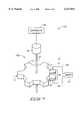
- FIG. 7is an illustrative representation of some of the components of the micro-electromechanical system of FIG. 6.
- the present inventionprovides a micro-electromechanical system voltage shifter including at least one node; a capacitor including plural opposing conductive plates; a micromechanical system configured to vary the capacitance of the capacitor; an electrical system configured to selectively couple the capacitor and the at least one node; and a mixer configured to output a product signal to synchronize the micromechanical system and the electrical system.
- a second aspect of the present inventionprovides a micro-electromechanical system comprising: an electrical system operating according to a first electrical quantity; a micromechanical system operating according to a mechanical quantity; and a synchronizer configured to convert the mechanical quantity to a second electrical quantity, and to mix the first electrical quantity and the second electrical quantity to generate a product signal to synchronize the electrical system and the micromechanical system.
- a micro-electromechanical system voltage shiftercomprising: a voltage source; an output node; a capacitor including plural opposing conductive plates; a first switch operable to selectively couple the voltage source with the capacitor to charge the capacitor to a first voltage; a micromechanical system configured to vary the capacitance of the capacitor to provide a second voltage across the capacitor, the micromechanical system being configured to operate according to a mechanical quantity; a second switch operable to selectively couple the capacitor with the output node to provide sampling of the second voltage of the capacitor; an electrical system configured to control the operation of at least one of the first switch and the second switch according to a first electrical quantity; wherein the capacitor is configured to convert the mechanical quantity to a second electrical quantity; a mixer configured to mix the first electrical quantity and the second electrical quantity to generate a product signal; and a low-pass filter configured to filter the product signal and apply the product signal to one of the micromechanical system and the electrical system to synchronize the electrical system and the micromechanical system.
- the low-pass filterpreferably integrate
- Another aspectprovides a method of synchronizing an electronic system and a micromechanical system of a micro-electromechanical system voltage shifter, the method comprising: providing a capacitor and at least one node; varying the capacitance of the capacitor using a micromechanical system; selectively coupling the capacitor with the at least one node using an electrical system to one of charge the capacitor and provide sampling of the voltage of the capacitor; and synchronizing the electrical system and the micromechanical system.
- the present inventionprovides a method of synchronizing an electronic system and a micromechanical system of a micro-electromechanical system, the method comprising: providing a micro-electromechanical system including an electrical system and a micromechanical system; operating the electrical system according to a first electrical quantity; operating the micromechanical system according to a mechanical quantity; converting the mechanical quantity to a second electrical quantity; generating a product signal from the first electrical quantity and the second electrical quantity; and synchronizing the electronic system and the micromechanical system using the product signal.
- micro-electromechanical systemis generally depicted as reference number 10.
- the depicted micro-electromechanical system 10includes a micromechanical system 12, an electrical system 14 and a synchronizer 16.
- micromechanical system 12is configured to operate according to a mechanical quantity (e.g., a position of a wheel).
- Electrical system 14is configured to operate according to an electrical quantity (e.g., a time-dependent voltage or current).
- Synchronizer 16is coupled with micromechanical system 12 and electrical system 14 and is configured to synchronize the operation of micromechanical system 12 and electrical system 14.
- synchronizer 16is configured to convert the mechanical quantity of micromechanical system 12 to an electrical quantity. Synchronizer 16 further mixes the electrical quantity of electrical system 14 with the electrical quantity of micromechanical system 12 to provide a product signal. The product signal may be integrated over time to provide a stable product signal. The generated product signal can be utilized to synchronize electrical system 14 and micromechanical system 12. In one embodiment, synchronizer 16 is configured to apply the product signal to electrical system 14 to provide synchronization. Alternatively, synchronizer 16 provides the product signal to micromechanical system 12 in another configuration to provide the synchronization.
- micro-electromechanical system 10an exemplary configuration of micro-electromechanical system 10 is described.
- the depicted configuration of micro-electromechanical system 10is operable to adjust electrical system 14 responsive to a mechanical quantity of micromechanical system 12 to provide synchronization of micromechanical system 12 and electrical system 14.
- micro-electromechanical system 10aanother configuration of micro-electromechanical system 10a is described.
- the configuration of micro-electromechanical system 10a depicted in FIG. 6-FIG. 7is operable to adjust micromechanical system 12 responsive to an electrical quantity of electrical system 14 to provide synchronization of micromechanical system 12 and electrical system 14.
- Micromechanical system 12is configured to operate at a mechanical quantity, such as rotational velocity, acceleration, etc.
- Micromechanical system 12is coupled with synchronizer 16.
- the illustrated synchronizer 16includes a converter 13, a mixer 15 and a low-pass filter 17.
- Converter 13is coupled with micromechanical system 12. Converter 13 is configured to convert the mechanical quantity of micromechanical system 12 into an electrical quantity.
- Mixer 15is coupled with converter 13 and electrical system 14. Electrical system 14 is configured to operate according to an electrical quantity, such as a time-dependent voltage or current.
- Mixer 15is configured to mix the electrical quantity outputted from converter 13 and the electrical quantity outputted from electrical system 14.
- Mixer 15generates a product signal responsive to the mixing of the electrical quantities.
- the product signalis a resulting quantity (e.g., current) which is indicative of the difference in frequency and/or phase between the two input quantities.
- Mixer 15is coupled with low-pass filter 17.
- Mixer 15applies the product signal to low-pass filter 17 which provides signal processing to remove higher order (e.g., second order and higher) components from the product signal, and thus integrates the product signal into a stable product signal.
- Low-pass filter 17outputs the product signal, also referred to as a control signal, which can be used as feedback to suitably alter either the micromechanical system or electrical system to provide synchronous operation.
- the product signalis outputted from low-pass filter 17 and applied to electrical system 14.
- electrical system 14includes a controller 18 which adjusts the operation of electrical system 14 to provide synchronization of electrical system 14 with micromechanical system 12 responsive to the product signal. Synchronous operation is substantially achieved when there is no frequency difference between the micromechanical and electrical systems. The control signal tends to drift to a zero value when synchronization is achieved.
- micro-electromechanical system 10is implemented as a micro-electromechanical system voltage shifter.
- the operation of an exemplary voltage shifteris described in U.S. patent application entitled Micro-Electromechanical Voltage Shifter and incorporated herein by reference above.
- the depicted voltage shifterincludes a micro-electromechanical gear wheel 11 and a parallel-plate capacitor 20 having a pair of capacitor plates 21, 22.
- Gear wheel 11comprises a micromechanical wheel formed using semiconductor processing techniques in the described embodiment.
- Gear wheel 11is circular in shape and comprises a plurality of teeth 13 which protrude radially from the center of gear wheel 11. Further, gear wheel 11 is positioned to a side of capacitor 20 and is configured to rotate about an axis X--X generally perpendicular to capacitor plates 21, 22 such that teeth 13 individually pass between capacitor plates 21, 22.
- gear wheel 11may be rotated to an "initial" position wherein a single tooth 13 is interposed between capacitor plates 21, 22.
- individual teeth 13are made of a dielectric material having a high dielectric constant such as polysilicon.
- capacitor 20has an initial capacitance of C 1 .
- capacitor 20Individual plates 21, 22 of capacitor 20 are coupled with nodes 24, 26.
- An external voltage supply(shown in FIG. 4) can be selectively coupled with nodes 24, 26 and operable to charge capacitor 20 to an initial voltage when a tooth 13 is interposed between plates 20, 21. After capacitor 20 is charged to the initial voltage, capacitor 20 is electrically isolated such that charges are conserved. In one embodiment, capacitor 20 is selectively disconnected from the voltage supply using one or more switches (also shown in FIG. 4).
- capacitor 20may be discharged or recharged numerous times during use.
- the depicted voltage shiftercan be configured to operate as a sensing device to monitor a mechanical condition, such as the flow of a fluid as represented by F.
- the flow F of fluidcauses rotation of wheel 11 in a counterclockwise direction about axis X--X. Rotational velocity of wheel 11 may be referred to as the mechanical quantity as previously indicated.
- Capacitor 20operates to convert the mechanical quantity into an electrical quantity.
- capacitor 20comprises converter 13 in the presently described embodiment. Rotation of wheel 11 creates a time-dependent capacitance within capacitor 20 intermediate nodes 24, 26 having a fundamental component of
- the output from capacitor 20is applied to mixer 15.
- the time-dependent capacitanceis utilized in the described embodiment to provide synchronization of micromechanical system 12 and electrical system 14.
- an exemplary electrical system 14is depicted.
- the illustrated electrical system 14is configured to provide selective charging of capacitor 20, as well as selective sampling or discharging of capacitor 20.
- Electrical system 14includes a charging device 30, such as a direct current (DC) battery, and a sampling device 32.
- Charging device 30is coupled with a node 31 and sampling device 32 is coupled with a node 33.
- DCdirect current
- Plural switches 34, 36are provided to implement selective coupling of charging device 30 and sampling device 32 with capacitor 20, respectively.
- First switch 34is implemented intermediate node 31 coupled with charging device 30 and node 24.
- Second switch 36is implemented intermediate node 33 coupled with sampling device 32 and node 24.
- Switches 34, 36operate to selectively couple node 24 with respective nodes 31, 33.
- Switches 34, 36are semiconductive (e.g., transistors) or micro-electromechanical in exemplary configurations.
- electrical system 14includes a switch control 38 to implement selective switching of charging device 30 and sampling device 32 with node 24 coupled with capacitor 20.
- Switch control 38is configured to control individual switches 34, 36.
- Switch control 38can be configured to control the operation of switches 34, 36 and selective coupling of charging device 30 and sampling device 32 with capacitor 20 responsive to the operation of micromechanical system 12. More specifically, switch control 38 can control switches 34, 36 responsive to the position of wheel 11. Synchronous operation of micromechanical system 12 and electrical system 14 is provided in accordance with the present invention.
- First switch 34operates to selectively couple charging device 30 with node 24.
- charging device 30is configured to charge capacitor 20 to the voltage of charging device 30.
- Switch control 38controls the selective charging of capacitor 20.
- Second switch 38selectively couples sampling device 32 with node 24. Sampling device 32 can be configured to measure the voltage across the capacitor 20, selectively discharge the voltage from capacitor 20, and/or provide other operations.
- Switch control 38controls the selective sampling and/or discharging of capacitor 20.
- FIG. 5one configuration for providing synchronization operations according to the present invention is described.
- the electrical system 14 of FIG. 4comprising switches 34, 36 and switch control 38 is depicted coupled with synchronizer 16.
- Synchronizer 16includes converter 13 comprising capacitor 20 in the presently described embodiment.
- Capacitor 20operates to provide mechanical quantity to electrical quantity conversion operations implemented by converter 13 of FIG. 2.
- Capacitor 20is coupled with a current-voltage (I-V) converter 44.
- Capacitor 20 and current-voltage converter 44comprise mixer 15 of FIG. 2 and are coupled with low-pass filter 17.
- Switch control 38 of electrical system 14includes a controller 40 coupled with a time-dependent voltage source 42, such as an alternating current (AC) voltage source.
- Voltage source 42is coupled with first switch 34 and second switch 36 and is configured to control the operation of switches 34, 36.
- Controller 40is additionally coupled with low-pass filter 17 and is configured to receive the filtered product signal from low-pass filter 17. Controller 40 is operable to control voltage source 42 responsive to the filtered product signal to provide synchronous operation of the mechanical system 12 and electrical system 14 of micro-electromechanical system 10.
- Voltage source 42is configured to operate according to the following equation
- the time-dependent voltage of voltage source 42is additionally applied to capacitor 20.
- the output of capacitor 20is applied to current-voltage converter 42.
- the application of the time-dependent voltage V 0 to the time-dependent capacitance C 0 of capacitor 20 and the operation of current-voltage converter 42implement the functions of mixer 15.
- the output of current-voltage converter 42comprises the product signal resulting from the mixing of C 0 and V 0 .
- the product signalis applied to low-pass filter 17 configured to remove higher order components from the product signal. More specifically, low-pass filter 17 outputs a filtered product signal substantially comprising the component proportional to
- ⁇represents the arbitrary phase between a fundamental frequency of the micromechanical system ( ⁇ mech ) and a fundamental frequency of the electrical system ( ⁇ elect )
- ⁇represents the arbitrary phase between a fundamental frequency of the micromechanical system ( ⁇ mech ) and a fundamental frequency of the electrical system ( ⁇ elect )
- Controller 40operates to control voltage source 42 to minimize differences between the fundamental frequencies of the micromechanical system 12 and the electrical system 14 ( ⁇ mech - ⁇ elect ) and the phase ⁇ between the systems 12, 14 responsive to the filtered product signal. Such adjusts the operation of electrical system 14 and provides synchronous operation of electrical system 14 and micromechanical system 12.
- micro-electromechanical system 10ais described.
- the depicted configuration of micro-electromechanical system 10ais operable to adjust micromechanical system 12a to provide synchronization of micromechanical system 12a and electrical system 14.
- Micromechanical system 12ais configured to operate at a mechanical quantity, such as angular velocity, acceleration, etc.
- a controller 19is coupled with micromechanical system 12a and is configured to control the operation of micromechanical system 12a.
- controller 19includes a voltage controlled oscillator (VCO) and a power amplifier configured to adjust the operation of micromechanical system 12a.
- VCOvoltage controlled oscillator
- Micromechanical system 12ais coupled with synchronizer 16.
- synchronizer 16can include converter 13, mixer 15 and low-pass filter 17.
- Converter 13can comprise capacitor 20 coupled with micromechanical system 12a.
- Converter 13is configured to convert the mechanical quantity received from micromechanical system 12a into an electrical quantity.
- Mixer 15is coupled with converter 13 and electrical system 14. Mixer 15 is configured to mix the electrical quantity outputted from converter 13 and an electrical quantity outputted from electrical system 14. Mixer 15 generates a product signal responsive to the mixing of the electrical quantities.
- Mixer 15is coupled with low-pass filter 17.
- Mixer 15applies the product signal to low-pass filter 17 which operates to remove higher order (e.g., second order and higher) components from the product signal.
- a filtered product signalcomprising a control signal is outputted from low-pass filter 17 and applied to controller 19.
- Controller 19adjusts the operation of micromechanical system 12 to provide synchronization of micromechanical system 12a with electrical system 14 responsive to the product signal.
- the depicted micro-electromechanical system 10ais implemented as a micro-electromechanical system voltage shifter similar to the previously described embodiment.
- the depicted voltage shifterincludes a micro-electromechanical gear wheel 11 and a parallel-plate capacitor 20 having a pair of capacitor plates 21, 22 as described above with reference to FIG. 2.
- Gear wheel 11is configured to rotate and teeth 13 individually pass intermediate capacitor plates 21, 22 of capacitor 20 implementing voltage shifting operations.
- the rotation of gear wheel 11may be referred to as a mechanical quantity.
- gear wheel 11 of micro-electromechanical system 10ais coupled with an axle 23 and a motor 25.
- gear wheel 11rotates responsive to motor 25 applying a torque to axle 23.
- Motor 25is controlled by controller 19.
- Motor 25can comprise a micro-electromechanical motor, such as a side-drive electrostatic motor.
- gear wheel 11may be implemented as a rotor of an micro-electromechanical motor.
- Capacitor 20operates as converter 13 shown in FIG. 6 to convert the mechanical quantity into an electrical quantity. Rotation of wheel 11 creates a time-dependent capacitance within capacitor 20 intermediate nodes 24, 26. The time-dependent capacitance can be utilized to provide synchronization between micromechanical system 12 and electrical system 14.
- the output from capacitor 20 functioning as converter 13may be applied to mixer 15 shown in FIG. 6.
- Mixer 15receives the electrical quantity from converter 13 corresponding to the mechanical quantity of micromechanical system 12a. Further, mixer 15 receives an electrical quantity from electrical system 14 of FIG. 6. Electrical system 14 can operate a plurality of switches as previously described or provide other operations according to the electrical quantity.
- Mixer 15outputs a product signal to low-pass filter 17 shown in FIG. 6.
- Low-pass filter 17applies a filtered product signal to controller 19.
- controller 19controls motor 25 responsive to the filtered product signal to provide synchronized operation of micromechanical system 12a and electrical system 14.
- controller 19synchronizes the rotation of gear wheel 11 with the operation of electrical system 14 in the presently described embodiment.
Landscapes
- Engineering & Computer Science (AREA)
- Power Engineering (AREA)
- Microelectronics & Electronic Packaging (AREA)
- Micromachines (AREA)
Abstract
Description
C=C.sub.0 *sin (ω.sub.mech t)
V=V.sub.0 *sin (ω.sub.elect t+θ)
sin ((ω.sub.mech -ω.sub.elect)t-θ)
Claims (32)
Priority Applications (1)
| Application Number | Priority Date | Filing Date | Title |
|---|---|---|---|
| US09/228,707US6127811A (en) | 1999-01-12 | 1999-01-12 | Micro-electromechanical system and voltage shifter, method of synchronizing an electronic system and a micromechanical system of a micro-electromechanical system |
Applications Claiming Priority (1)
| Application Number | Priority Date | Filing Date | Title |
|---|---|---|---|
| US09/228,707US6127811A (en) | 1999-01-12 | 1999-01-12 | Micro-electromechanical system and voltage shifter, method of synchronizing an electronic system and a micromechanical system of a micro-electromechanical system |
Publications (1)
| Publication Number | Publication Date |
|---|---|
| US6127811Atrue US6127811A (en) | 2000-10-03 |
Family
ID=22858271
Family Applications (1)
| Application Number | Title | Priority Date | Filing Date |
|---|---|---|---|
| US09/228,707Expired - LifetimeUS6127811A (en) | 1999-01-12 | 1999-01-12 | Micro-electromechanical system and voltage shifter, method of synchronizing an electronic system and a micromechanical system of a micro-electromechanical system |
Country Status (1)
| Country | Link |
|---|---|
| US (1) | US6127811A (en) |
Cited By (55)
| Publication number | Priority date | Publication date | Assignee | Title |
|---|---|---|---|---|
| US6438010B1 (en)* | 2001-03-02 | 2002-08-20 | Onetta, Inc. | Drive circuits for microelectromechanical systems devices |
| US6445162B1 (en)* | 2001-02-06 | 2002-09-03 | Quallion Llc | Detecting a remaining battery capacity and a battery remaining capacity circuit |
| US20030025983A1 (en)* | 2001-07-18 | 2003-02-06 | Stmicroelectronics S.R.L | Self-calibrating oversampling electromechanical modulator and self-calibration method |
| US20040054364A1 (en)* | 2002-02-08 | 2004-03-18 | Ernest Aranyi | Ultrasonic surgical instrument |
| US20050131390A1 (en)* | 2002-04-25 | 2005-06-16 | Russell Heinrich | Surgical instruments including mems devices |
| US20060278681A1 (en)* | 2005-06-03 | 2006-12-14 | Viola Frank J | Battery powered surgical instrument |
| US20060278680A1 (en)* | 2005-06-03 | 2006-12-14 | Viola Frank J | Surgical stapler with timer and feedback display |
| GB2436896A (en)* | 2006-04-03 | 2007-10-10 | Rolls Royce Plc | A high voltage dc generator using varying capacitance. |
| US20070270784A1 (en)* | 2006-05-19 | 2007-11-22 | Ethicon Endo-Surgery, Inc. | Electric surgical instrument with optimized power supply and drive |
| US20080185419A1 (en)* | 2006-05-19 | 2008-08-07 | Smith Kevin W | Electrically Self-Powered Surgical Instrument With Cryptographic Identification of Interchangeable Part |
| US20080214967A1 (en)* | 2004-02-17 | 2008-09-04 | Ernest Aranyi | Ultrasonic surgical instrument |
| US20090001595A1 (en)* | 2007-06-29 | 2009-01-01 | Ulrike Roessner | Integrated Circuit, Intermediate Structure and a Method of Fabricating a Semiconductor Structure |
| US20090057369A1 (en)* | 2005-07-26 | 2009-03-05 | Smith Kevin W | Electrically Self-Powered Surgical Instrument With Manual Release |
| US7648055B2 (en) | 2007-03-15 | 2010-01-19 | Tyco Healthcare Group Lp | Surgical stapling apparatus with powered articulation |
| US20100096431A1 (en)* | 2007-02-12 | 2010-04-22 | Ethicon Endo-Surgery, Inc. | Active braking electrical surgical iinstrument and method for braking such an instrument |
| US20100186219A1 (en)* | 2006-05-19 | 2010-07-29 | Smith Kevin W | Force Switch |
| US7823760B2 (en) | 2007-05-01 | 2010-11-02 | Tyco Healthcare Group Lp | Powered surgical stapling device platform |
| US7922063B2 (en) | 2007-10-31 | 2011-04-12 | Tyco Healthcare Group, Lp | Powered surgical instrument |
| US7931660B2 (en) | 2007-05-10 | 2011-04-26 | Tyco Healthcare Group Lp | Powered tacker instrument |
| US7950560B2 (en) | 2007-04-13 | 2011-05-31 | Tyco Healthcare Group Lp | Powered surgical instrument |
| US8800837B2 (en) | 2007-04-13 | 2014-08-12 | Covidien Lp | Powered surgical instrument |
| US8821514B2 (en) | 2009-06-08 | 2014-09-02 | Covidien Lp | Powered tack applier |
| US9554803B2 (en) | 2005-07-26 | 2017-01-31 | Ethicon Endo-Surgery, Llc | Electrically self-powered surgical instrument with manual release |
| US9662116B2 (en) | 2006-05-19 | 2017-05-30 | Ethicon, Llc | Electrically self-powered surgical instrument with cryptographic identification of interchangeable part |
| US9848872B2 (en) | 2005-07-26 | 2017-12-26 | Ethicon Llc | Surgical stapling and cutting device |
| US10022142B2 (en) | 2001-02-08 | 2018-07-17 | Covidien Lp | Ultrasonic surgical instrument |
| US10285694B2 (en) | 2001-10-20 | 2019-05-14 | Covidien Lp | Surgical stapler with timer and feedback display |
| US10314583B2 (en) | 2005-07-26 | 2019-06-11 | Ethicon Llc | Electrically self-powered surgical instrument with manual release |
| US10524785B2 (en) | 2007-04-13 | 2020-01-07 | Covidien Lp | Powered surgical instrument |
| US10987104B2 (en) | 2017-10-30 | 2021-04-27 | Covidien Lp | Apparatus for endoscopic procedures |
| US11197734B2 (en) | 2018-10-30 | 2021-12-14 | Covidien Lp | Load sensing devices for use in surgical instruments |
| US11202635B2 (en) | 2019-02-04 | 2021-12-21 | Covidien Lp | Programmable distal tilt position of end effector for powered surgical devices |
| US11207066B2 (en) | 2017-10-30 | 2021-12-28 | Covidien Lp | Apparatus for endoscopic procedures |
| US11219461B2 (en) | 2019-03-08 | 2022-01-11 | Covidien Lp | Strain gauge stabilization in a surgical device |
| US11259801B2 (en) | 2007-04-13 | 2022-03-01 | Covidien Lp | Powered surgical instrument |
| US11291443B2 (en) | 2005-06-03 | 2022-04-05 | Covidien Lp | Surgical stapler with timer and feedback display |
| US11311295B2 (en) | 2017-05-15 | 2022-04-26 | Covidien Lp | Adaptive powered stapling algorithm with calibration factor |
| US11369372B2 (en) | 2018-11-28 | 2022-06-28 | Covidien Lp | Surgical stapler adapter with flexible cable assembly, flexible fingers, and contact clips |
| US11376006B2 (en) | 2019-02-06 | 2022-07-05 | Covidien Lp | End effector force measurement with digital drive circuit |
| US11458244B2 (en) | 2020-02-07 | 2022-10-04 | Covidien Lp | Irrigating surgical apparatus with positive pressure fluid |
| US11497490B2 (en) | 2018-07-09 | 2022-11-15 | Covidien Lp | Powered surgical devices including predictive motor control |
| US11553913B2 (en) | 2020-02-11 | 2023-01-17 | Covidien Lp | Electrically-determining tissue cut with surgical stapling apparatus |
| US11622768B2 (en) | 2020-07-13 | 2023-04-11 | Covidien Lp | Methods and structure for confirming proper assembly of powered surgical stapling systems |
| US11653919B2 (en) | 2020-11-24 | 2023-05-23 | Covidien Lp | Stapler line reinforcement continuity |
| US11684362B2 (en) | 2021-06-07 | 2023-06-27 | Covidien Lp | Handheld electromechanical surgical system |
| US11744580B2 (en) | 2020-11-24 | 2023-09-05 | Covidien Lp | Long stapler reloads with continuous cartridge |
| US11751873B2 (en) | 2005-07-26 | 2023-09-12 | Cilag Gmbh International | Electrically powered surgical instrument with manual release |
| US11771432B2 (en) | 2021-06-29 | 2023-10-03 | Covidien Lp | Stapling and cutting to default values in the event of strain gauge data integrity loss |
| US11832823B2 (en) | 2022-02-08 | 2023-12-05 | Covidien Lp | Determination of anvil release during anastomosis |
| US12016556B2 (en) | 2021-05-03 | 2024-06-25 | Covidien Lp | Handheld electromechanical surgical system |
| US12029470B2 (en) | 2020-05-21 | 2024-07-09 | Covidien Lp | Simultaneous RF monopolar calibration using a shared return electrode |
| US12137902B2 (en) | 2018-07-25 | 2024-11-12 | Covidien Lp | Adaptive anti-twitch algorithm for powered surgical devices |
| US12161341B2 (en) | 2021-09-07 | 2024-12-10 | Covidien Lp | Slow speed staple and staple relaxation for stapling optimization |
| US12185949B2 (en) | 2017-10-30 | 2025-01-07 | Covidien Lp | Apparatus for endoscopic procedures |
| US12193884B2 (en) | 2020-11-17 | 2025-01-14 | Covidien Lp | Contactless force measurement of motor torque in powered surgical device |
Citations (3)
| Publication number | Priority date | Publication date | Assignee | Title |
|---|---|---|---|---|
| US5610335A (en)* | 1993-05-26 | 1997-03-11 | Cornell Research Foundation | Microelectromechanical lateral accelerometer |
| US5808527A (en)* | 1996-12-21 | 1998-09-15 | Hughes Electronics Corporation | Tunable microwave network using microelectromechanical switches |
| US5889389A (en)* | 1998-01-28 | 1999-03-30 | Vlsi Technology, Inc. | Micro-electromechanical voltage shifter |
- 1999
- 1999-01-12USUS09/228,707patent/US6127811A/ennot_activeExpired - Lifetime
Patent Citations (3)
| Publication number | Priority date | Publication date | Assignee | Title |
|---|---|---|---|---|
| US5610335A (en)* | 1993-05-26 | 1997-03-11 | Cornell Research Foundation | Microelectromechanical lateral accelerometer |
| US5808527A (en)* | 1996-12-21 | 1998-09-15 | Hughes Electronics Corporation | Tunable microwave network using microelectromechanical switches |
| US5889389A (en)* | 1998-01-28 | 1999-03-30 | Vlsi Technology, Inc. | Micro-electromechanical voltage shifter |
Non-Patent Citations (8)
| Title |
|---|
| Electromagnetics, Chapter 2, The Static Electric Field, Part 2 , pp. 62 65. no date.* |
| Electromagnetics, Chapter 2, The Static Electric Field, Part 2, pp. 62-65. no date. |
| Gary K. Fedder, et al., Journal of Microelectromechanical Systems, vol. 5, No. 4, Multimode Digital Control of a Suspended Polysisicon Microstructure , Dec. 1996, pp. 283 286.* |
| Gary K. Fedder, et al., Journal of Microelectromechanical Systems, vol. 5, No. 4, Multimode Digital Control of a Suspended Polysisicon Microstructure, Dec. 1996, pp. 283-286. |
| Michael J. Daneman, et al., Journal of Microelectromechanical Systems, vol. 5, No. 3, Linear Microvibromotor of Positioning Optical Components , Sep. 1996, pp. 159 165.* |
| Michael J. Daneman, et al., Journal of Microelectromechanical Systems, vol. 5, No. 3, Linear Microvibromotor of Positioning Optical Components, Sep. 1996, pp. 159-165. |
| S. T. Cho, et al., An Ultrasensitive Silicon Pressure Based Flowmeter , (1989). no month.* |
| S. T. Cho, et al., An Ultrasensitive Silicon Pressure-Based Flowmeter, (1989). no month. |
Cited By (182)
| Publication number | Priority date | Publication date | Assignee | Title |
|---|---|---|---|---|
| US6445162B1 (en)* | 2001-02-06 | 2002-09-03 | Quallion Llc | Detecting a remaining battery capacity and a battery remaining capacity circuit |
| WO2003001643A1 (en)* | 2001-02-06 | 2003-01-03 | Quallion Llc | Detecting a remaining battery capacity and a battery remaining capacity circuit |
| US10022142B2 (en) | 2001-02-08 | 2018-07-17 | Covidien Lp | Ultrasonic surgical instrument |
| US6438010B1 (en)* | 2001-03-02 | 2002-08-20 | Onetta, Inc. | Drive circuits for microelectromechanical systems devices |
| US20070107492A1 (en)* | 2001-07-18 | 2007-05-17 | Stmicroelectronics S.R.L. | Self-calibrating oversampling electromechanical modulator and self-calibration method |
| US20030025983A1 (en)* | 2001-07-18 | 2003-02-06 | Stmicroelectronics S.R.L | Self-calibrating oversampling electromechanical modulator and self-calibration method |
| US7461553B2 (en)* | 2001-07-18 | 2008-12-09 | Stmicroelectronics S.R.L. | Self-calibrating oversampling electromechanical modulator and self-calibration method |
| US7155979B2 (en)* | 2001-07-18 | 2007-01-02 | Stmicroelectronics S.R.L. | Self-calibrating oversampling electromechanical modulator and self-calibration method |
| US10285694B2 (en) | 2001-10-20 | 2019-05-14 | Covidien Lp | Surgical stapler with timer and feedback display |
| US20040054364A1 (en)* | 2002-02-08 | 2004-03-18 | Ernest Aranyi | Ultrasonic surgical instrument |
| US9561031B2 (en) | 2002-04-25 | 2017-02-07 | Covidien Lp | Surgical instrument including MEMS devices |
| US9295468B2 (en) | 2002-04-25 | 2016-03-29 | Covidien Lp | Surgical instruments including MEMS devices |
| US9962159B2 (en) | 2002-04-25 | 2018-05-08 | Covidien Lp | Surgical instruments including MEMS devices |
| US8808311B2 (en) | 2002-04-25 | 2014-08-19 | Covidien Lp | Surgical instruments including MEMS devices |
| US20110144640A1 (en)* | 2002-04-25 | 2011-06-16 | Tyco Healthcare Group Lp | Surgical instruments including mems devices |
| US20050131390A1 (en)* | 2002-04-25 | 2005-06-16 | Russell Heinrich | Surgical instruments including mems devices |
| US10299788B2 (en) | 2002-04-25 | 2019-05-28 | Covidien Lp | Surgical instruments including MEMS devices |
| US10575849B2 (en) | 2002-04-25 | 2020-03-03 | Covidien Lp | Surgical instruments including MEMS devices |
| US20080214967A1 (en)* | 2004-02-17 | 2008-09-04 | Ernest Aranyi | Ultrasonic surgical instrument |
| US7845534B2 (en) | 2005-06-03 | 2010-12-07 | Tyco Healthcare Group Lp | Surgical stapler with timer and feedback display |
| US12193667B2 (en) | 2005-06-03 | 2025-01-14 | Covidien Lp | Battery powered surgical instrument |
| US11413041B2 (en) | 2005-06-03 | 2022-08-16 | Covidien Lp | Battery powered surgical instrument |
| US8505802B2 (en) | 2005-06-03 | 2013-08-13 | Covidien Lp | Surgical stapler with timer and feedback display |
| US11291443B2 (en) | 2005-06-03 | 2022-04-05 | Covidien Lp | Surgical stapler with timer and feedback display |
| US20060278681A1 (en)* | 2005-06-03 | 2006-12-14 | Viola Frank J | Battery powered surgical instrument |
| US20100096434A1 (en)* | 2005-06-03 | 2010-04-22 | Viola Frank J | Surgical stapler with timer and feedback display |
| US7757925B2 (en) | 2005-06-03 | 2010-07-20 | Tyco Healthcare Group Lp | Battery powered surgical instrument |
| US8348125B2 (en) | 2005-06-03 | 2013-01-08 | Covidien Lp | Battery powered surgical instrument |
| US10881404B2 (en) | 2005-06-03 | 2021-01-05 | Covidien Lp | Battery powered surgical instrument |
| US7461767B2 (en) | 2005-06-03 | 2008-12-09 | Tyco Healthcare Group Lp | Battery powered surgical instrument |
| US20060278680A1 (en)* | 2005-06-03 | 2006-12-14 | Viola Frank J | Surgical stapler with timer and feedback display |
| US8505799B2 (en) | 2005-06-03 | 2013-08-13 | Covidien Lp | Battery powered surgical instrument |
| US11523826B2 (en) | 2005-06-03 | 2022-12-13 | Covidien Lp | Battery powered surgical instrument |
| US7870989B2 (en) | 2005-06-03 | 2011-01-18 | Tyco Healthcare Group Lp | Surgical stapler with timer and feedback display |
| US7909221B2 (en) | 2005-06-03 | 2011-03-22 | Tyco Healthcare Group Lp | Battery powered surgical instrument |
| US20110068146A1 (en)* | 2005-06-03 | 2011-03-24 | Viola Frank J | Surgical Stapler With Timer And Feedback Display |
| US11701118B2 (en) | 2005-06-03 | 2023-07-18 | Coviden Lp | Battery powered surgical instrument |
| US10188391B2 (en) | 2005-06-03 | 2019-01-29 | Covidien Lp | Battery powered surgical instrument |
| US10098638B2 (en) | 2005-06-03 | 2018-10-16 | Covidien Lp | Battery powered surgical instrument |
| US9370361B2 (en) | 2005-06-03 | 2016-06-21 | Covidien Lp | Surgical stapler with timer and feedback display |
| US20080197167A1 (en)* | 2005-06-03 | 2008-08-21 | Tyco Healthcare Group Lp | Surgical stapler with timer and feedback display |
| US9585659B2 (en) | 2005-06-03 | 2017-03-07 | Covidien Lp | Battery powered surgical instrument |
| US7464847B2 (en) | 2005-06-03 | 2008-12-16 | Tyco Healthcare Group Lp | Surgical stapler with timer and feedback display |
| US9987005B2 (en) | 2005-06-03 | 2018-06-05 | Covidien Lp | Surgical stapler with timer and feedback display |
| US8157150B2 (en) | 2005-06-03 | 2012-04-17 | Tyco Healthcare Group Lp | Surgical stapler with timer and feedback display |
| US8052024B2 (en) | 2005-06-03 | 2011-11-08 | Tyco Healthcare Group Lp | Surgical stapler with timer and feedback display |
| US8132705B2 (en) | 2005-06-03 | 2012-03-13 | Tyco Healthcare Group Lp | Surgical stapler with timer and feedback display |
| US9554803B2 (en) | 2005-07-26 | 2017-01-31 | Ethicon Endo-Surgery, Llc | Electrically self-powered surgical instrument with manual release |
| US12059150B2 (en) | 2005-07-26 | 2024-08-13 | Cilag Gmbh International | Surgical stapling and cutting device |
| US9848872B2 (en) | 2005-07-26 | 2017-12-26 | Ethicon Llc | Surgical stapling and cutting device |
| US20110210156A1 (en)* | 2005-07-26 | 2011-09-01 | Smith Kevin W | Electrically Self-Powered Surgical Instrument With Manual Release |
| US11751873B2 (en) | 2005-07-26 | 2023-09-12 | Cilag Gmbh International | Electrically powered surgical instrument with manual release |
| US9855038B2 (en) | 2005-07-26 | 2018-01-02 | Ethicon Llc | Surgical stapling and cutting device |
| US7959050B2 (en) | 2005-07-26 | 2011-06-14 | Ethicon Endo-Surgery, Inc | Electrically self-powered surgical instrument with manual release |
| US10314583B2 (en) | 2005-07-26 | 2019-06-11 | Ethicon Llc | Electrically self-powered surgical instrument with manual release |
| US11172930B2 (en) | 2005-07-26 | 2021-11-16 | Cilag Gmbh International | Electrically self-powered surgical instrument with manual release |
| US11234695B2 (en) | 2005-07-26 | 2022-02-01 | Cilag Gmbh International | Surgical stapling and cutting device |
| US8672951B2 (en) | 2005-07-26 | 2014-03-18 | Ethicon Endo-Surgery, Inc. | Electrically self-powered surgical instrument with manual release |
| US20090057369A1 (en)* | 2005-07-26 | 2009-03-05 | Smith Kevin W | Electrically Self-Powered Surgical Instrument With Manual Release |
| GB2436896A (en)* | 2006-04-03 | 2007-10-10 | Rolls Royce Plc | A high voltage dc generator using varying capacitance. |
| US9675348B2 (en) | 2006-05-19 | 2017-06-13 | Ethicon Llc | Electrical surgical instrument with knife return |
| US9757127B2 (en) | 2006-05-19 | 2017-09-12 | Ethicon Llc | Electrical surgical instrument with optimal tissue compression |
| US8573462B2 (en) | 2006-05-19 | 2013-11-05 | Ethicon Endo-Surgery, Inc. | Electrical surgical instrument with optimized power supply and drive |
| US8573459B2 (en) | 2006-05-19 | 2013-11-05 | Ethicon Endo-Surgery, Inc | Optimal tissue compression electrical surgical instrument |
| US8592700B2 (en) | 2006-05-19 | 2013-11-26 | Ethicon Endo-Surgery, Inc. | Force switch |
| US8627995B2 (en) | 2006-05-19 | 2014-01-14 | Ethicon Endo-Sugery, Inc. | Electrically self-powered surgical instrument with cryptographic identification of interchangeable part |
| US20100258611A1 (en)* | 2006-05-19 | 2010-10-14 | Smith Kevin W | Electrical Surgical Stapling Instrument with Tissue Compressive Force Control |
| US20070270784A1 (en)* | 2006-05-19 | 2007-11-22 | Ethicon Endo-Surgery, Inc. | Electric surgical instrument with optimized power supply and drive |
| US12096933B2 (en) | 2006-05-19 | 2024-09-24 | Cllag GmbH International | Electrical surgical instrument with differential rate of closing motion speed |
| US20070270790A1 (en)* | 2006-05-19 | 2007-11-22 | Ethicon Endo-Surgery, Inc. | Electrical surgical instrument with optimized power supply and drive |
| US10586669B2 (en) | 2006-05-19 | 2020-03-10 | Ethicon-Endo Surgery, Inc. | Force switch |
| US12009166B2 (en) | 2006-05-19 | 2024-06-11 | Cilag Gmbh International | Force switch |
| US8827138B2 (en) | 2006-05-19 | 2014-09-09 | Ethicon Endo-Sugery, Inc. | Method for operating an electrical surgical instrument with optimal tissue compression |
| US8844791B2 (en) | 2006-05-19 | 2014-09-30 | Ethicon Endo-Surgery, Inc. | Electrical surgical instrument with optimal tissue compression |
| US8872046B2 (en) | 2006-05-19 | 2014-10-28 | Ethicon Endo-Surgery, Inc. | Force switch |
| US11974745B2 (en) | 2006-05-19 | 2024-05-07 | Cilag Gmbh International | Electrically self-powered surgical instrument with cryptographic identification of interchangeable part |
| US11759203B2 (en)* | 2006-05-19 | 2023-09-19 | Cilag Gmbh International | Electrical surgical instrument with minimum closure distance for staple firing control |
| US10217582B2 (en) | 2006-05-19 | 2019-02-26 | Ethicon Endo-Surgery, Inc. | Force switch |
| US20080185419A1 (en)* | 2006-05-19 | 2008-08-07 | Smith Kevin W | Electrically Self-Powered Surgical Instrument With Cryptographic Identification of Interchangeable Part |
| US20080245841A1 (en)* | 2006-05-19 | 2008-10-09 | Smith Kevin W | Method for Operating an Electrical Surgical Instrument with Optimal Tissue Compression |
| US20080251569A1 (en)* | 2006-05-19 | 2008-10-16 | Smith Kevin W | Optimal Tissue Compression Electrical Surgical Instrument |
| US8292157B2 (en) | 2006-05-19 | 2012-10-23 | Ethicon Endo-Surgery, Inc. | Electrical surgical instrument with optimized power supply and drive |
| US9439651B2 (en) | 2006-05-19 | 2016-09-13 | Ethicon Endo-Surgery, Llc | Methods for cryptographic identification of interchangeable parts for surgical instruments |
| US8286846B2 (en) | 2006-05-19 | 2012-10-16 | Ethicon Endo-Surgery, Inc. | Method for operating an electrical surgical instrument with optimal tissue compression |
| US10675022B2 (en) | 2006-05-19 | 2020-06-09 | Ethicon Llc | Electrical surgical instrument with optimal tissue compression |
| US8269121B2 (en) | 2006-05-19 | 2012-09-18 | Ethicon Endo-Surgery, Inc. | Force switch |
| US20100230465A1 (en)* | 2006-05-19 | 2010-09-16 | Smith Kevin W | Methods for Cryptographic Identification of Interchangeable Parts for Surgical Instruments |
| US9622744B2 (en) | 2006-05-19 | 2017-04-18 | Ethicon Endo-Surgery, Llc | Electrical surgical instrument with one-handed operation |
| US9666389B2 (en) | 2006-05-19 | 2017-05-30 | Ethicon Endo-Surgery, Inc. | Force switch |
| US9662116B2 (en) | 2006-05-19 | 2017-05-30 | Ethicon, Llc | Electrically self-powered surgical instrument with cryptographic identification of interchangeable part |
| US11183349B2 (en) | 2006-05-19 | 2021-11-23 | Ethicon Endo-Surgery, Inc | Force switch |
| US8028885B2 (en) | 2006-05-19 | 2011-10-04 | Ethicon Endo-Surgery, Inc. | Electric surgical instrument with optimized power supply and drive |
| US9681873B2 (en)* | 2006-05-19 | 2017-06-20 | Ethicon Llc | Electrical surgical stapling instrument with tissue compressive force control |
| US9687234B2 (en) | 2006-05-19 | 2017-06-27 | Ethicon L.L.C. | Electrical surgical instrument with optimized power supply and drive |
| US8038046B2 (en) | 2006-05-19 | 2011-10-18 | Ethicon Endo-Surgery, Inc. | Electrical surgical instrument with optimized power supply and drive |
| US9713473B2 (en) | 2006-05-19 | 2017-07-25 | Ethicon Endo-Surgery, Inc. | Active braking electrical surgical instrument and method for braking such an instrument |
| US20170238933A1 (en)* | 2006-05-19 | 2017-08-24 | Ethicon Endo-Surgery, Llc | Electrical Surgical Instrument with Minimum Closure Distance for Staple Firing Control |
| US10314592B2 (en) | 2006-05-19 | 2019-06-11 | Ethicon Llc | Electrically self-powered surgical instrument with cryptographic identification of interchangeable part |
| US11172931B2 (en) | 2006-05-19 | 2021-11-16 | Cilag Gmbh International | Electrically self-powered surgical instrument with cryptographic identification of interchangeable part |
| US20100186219A1 (en)* | 2006-05-19 | 2010-07-29 | Smith Kevin W | Force Switch |
| US9934920B2 (en) | 2006-05-19 | 2018-04-03 | Ethicon Endo-Surgery, Inc. | Force switch |
| US9901340B2 (en) | 2006-05-19 | 2018-02-27 | Ethicon Endo-Surgery, Inc. | Active braking electrical surgical instrument and method for braking such an instrument |
| US20100096431A1 (en)* | 2007-02-12 | 2010-04-22 | Ethicon Endo-Surgery, Inc. | Active braking electrical surgical iinstrument and method for braking such an instrument |
| US8627993B2 (en) | 2007-02-12 | 2014-01-14 | Ethicon Endo-Surgery, Inc. | Active braking electrical surgical instrument and method for braking such an instrument |
| US8092493B2 (en) | 2007-03-15 | 2012-01-10 | Tyco Healthcare Group Lp | Surgical stapling apparatus with powered articulation |
| US9700314B2 (en) | 2007-03-15 | 2017-07-11 | Covidien Lp | Surgical stapling apparatus with powered articulation |
| US8240537B2 (en) | 2007-03-15 | 2012-08-14 | Tyco Healthcare Group Lp | Surgical stapling apparatus with powered articulation |
| US8006887B2 (en) | 2007-03-15 | 2011-08-30 | Tyco Healthcare Group Lp | Surgical stapling apparatus with powered articulation |
| US7648055B2 (en) | 2007-03-15 | 2010-01-19 | Tyco Healthcare Group Lp | Surgical stapling apparatus with powered articulation |
| US9192381B2 (en) | 2007-03-15 | 2015-11-24 | Covidien Lp | Surgical stapling apparatus with powered articulation |
| US8419768B2 (en) | 2007-03-15 | 2013-04-16 | Covidien Lp | Surgical stapling apparatus with powered articulation |
| US10653416B2 (en) | 2007-04-13 | 2020-05-19 | Covidien Lp | Powered surgical instrument |
| US8685004B2 (en) | 2007-04-13 | 2014-04-01 | Covidien Lp | Powered surgical instrument |
| US10321902B2 (en) | 2007-04-13 | 2019-06-18 | Covidien Lp | Powered surgical instrument |
| US10357231B1 (en) | 2007-04-13 | 2019-07-23 | Covidien Lp | Powered surgical instrument |
| US11832813B2 (en) | 2007-04-13 | 2023-12-05 | Covidien Lp | Powered surgical instrument |
| US10524785B2 (en) | 2007-04-13 | 2020-01-07 | Covidien Lp | Powered surgical instrument |
| US8800837B2 (en) | 2007-04-13 | 2014-08-12 | Covidien Lp | Powered surgical instrument |
| US11464509B2 (en) | 2007-04-13 | 2022-10-11 | Covidien Lp | Powered surgical instrument |
| US11369370B2 (en) | 2007-04-13 | 2022-06-28 | Covidien Lp | Powered surgical instrument |
| US8506557B2 (en) | 2007-04-13 | 2013-08-13 | Covidien Lp | Powered surgical instrument |
| US11324499B2 (en) | 2007-04-13 | 2022-05-10 | Covidien Lp | Powered surgical instrument |
| US10799238B2 (en) | 2007-04-13 | 2020-10-13 | Covidien Lp | Powered surgical instrument |
| US7950560B2 (en) | 2007-04-13 | 2011-05-31 | Tyco Healthcare Group Lp | Powered surgical instrument |
| US8267924B2 (en) | 2007-04-13 | 2012-09-18 | Tyco Healthcare Group Lp | Powered surgical instrument |
| US11090044B2 (en) | 2007-04-13 | 2021-08-17 | Covidien Lp | Powered surgical instrument |
| US11259802B2 (en) | 2007-04-13 | 2022-03-01 | Covidien Lp | Powered surgical instrument |
| US9814452B2 (en) | 2007-04-13 | 2017-11-14 | Covidien Lp | Powered surgical instrument |
| US11259801B2 (en) | 2007-04-13 | 2022-03-01 | Covidien Lp | Powered surgical instrument |
| US12303126B2 (en) | 2007-04-13 | 2025-05-20 | Covidien Lp | Powered surgical instrument |
| US11207069B2 (en) | 2007-05-01 | 2021-12-28 | Covidien Lp | Powered surgical stapling device platform |
| US8459521B2 (en) | 2007-05-01 | 2013-06-11 | Covidien Lp | Powered surgical stapling device platform |
| US9585664B2 (en) | 2007-05-01 | 2017-03-07 | Covidien Lp | Powered surgical stapling device platform |
| US10542983B2 (en) | 2007-05-01 | 2020-01-28 | Covidien Lp | Powered surgical stapling device platform |
| US9364222B2 (en) | 2007-05-01 | 2016-06-14 | Covidien Lp | Powered surgical stapling device platform |
| US7823760B2 (en) | 2007-05-01 | 2010-11-02 | Tyco Healthcare Group Lp | Powered surgical stapling device platform |
| US7931660B2 (en) | 2007-05-10 | 2011-04-26 | Tyco Healthcare Group Lp | Powered tacker instrument |
| US8328823B2 (en) | 2007-05-10 | 2012-12-11 | Covidien Lp | Powered tacker instrument |
| US7858514B2 (en)* | 2007-06-29 | 2010-12-28 | Qimonda Ag | Integrated circuit, intermediate structure and a method of fabricating a semiconductor structure |
| US20090001595A1 (en)* | 2007-06-29 | 2009-01-01 | Ulrike Roessner | Integrated Circuit, Intermediate Structure and a Method of Fabricating a Semiconductor Structure |
| US8201721B2 (en) | 2007-10-31 | 2012-06-19 | Tyco Healthcare Group Lp | Powered surgical instrument |
| US11944293B2 (en) | 2007-10-31 | 2024-04-02 | Covidien Lp | Powered surgical instrument |
| US7922063B2 (en) | 2007-10-31 | 2011-04-12 | Tyco Healthcare Group, Lp | Powered surgical instrument |
| US9113876B2 (en) | 2007-10-31 | 2015-08-25 | Covidien Lp | Powered surgical instrument |
| US9241712B2 (en) | 2007-10-31 | 2016-01-26 | Covidien Lp | Powered surgical instrument |
| US10376262B2 (en) | 2007-10-31 | 2019-08-13 | Covidien Lp | Powered surgical instrument |
| US8925783B2 (en) | 2007-10-31 | 2015-01-06 | Covidien Lp | Powered surgical instrument |
| US11246589B2 (en) | 2007-10-31 | 2022-02-15 | Covidien Lp | Powered surgical instrument |
| US9668731B2 (en) | 2007-10-31 | 2017-06-06 | Covidien Lp | Powered surgical instrument |
| US8821514B2 (en) | 2009-06-08 | 2014-09-02 | Covidien Lp | Powered tack applier |
| US11311295B2 (en) | 2017-05-15 | 2022-04-26 | Covidien Lp | Adaptive powered stapling algorithm with calibration factor |
| US11627963B2 (en) | 2017-10-30 | 2023-04-18 | Covidien Lp | Apparatus for endoscopic procedures |
| US10987104B2 (en) | 2017-10-30 | 2021-04-27 | Covidien Lp | Apparatus for endoscopic procedures |
| US12185949B2 (en) | 2017-10-30 | 2025-01-07 | Covidien Lp | Apparatus for endoscopic procedures |
| US11207066B2 (en) | 2017-10-30 | 2021-12-28 | Covidien Lp | Apparatus for endoscopic procedures |
| US11937813B2 (en) | 2017-10-30 | 2024-03-26 | Covidien Lp | Apparatus for endoscopic procedures |
| US11771427B2 (en) | 2017-10-30 | 2023-10-03 | Covidien Lp | Apparatus for endoscopic procedures |
| US11497490B2 (en) | 2018-07-09 | 2022-11-15 | Covidien Lp | Powered surgical devices including predictive motor control |
| US12137902B2 (en) | 2018-07-25 | 2024-11-12 | Covidien Lp | Adaptive anti-twitch algorithm for powered surgical devices |
| US11197734B2 (en) | 2018-10-30 | 2021-12-14 | Covidien Lp | Load sensing devices for use in surgical instruments |
| US11896439B2 (en) | 2018-10-30 | 2024-02-13 | Covidien Lp | Load sensing devices for use in surgical instruments |
| US12029422B2 (en) | 2018-11-28 | 2024-07-09 | Covidien Lp | Surgical stapler adapter with flexible cable assembly, flexible fingers, and contact clips |
| US11369372B2 (en) | 2018-11-28 | 2022-06-28 | Covidien Lp | Surgical stapler adapter with flexible cable assembly, flexible fingers, and contact clips |
| US11202635B2 (en) | 2019-02-04 | 2021-12-21 | Covidien Lp | Programmable distal tilt position of end effector for powered surgical devices |
| US11723664B2 (en) | 2019-02-04 | 2023-08-15 | Covidien Lp | Programmable distal tilt position of end effector for powered surgical devices |
| US11950783B2 (en) | 2019-02-06 | 2024-04-09 | Covidien Lp | End effector force measurement with digital drive circuit |
| US11376006B2 (en) | 2019-02-06 | 2022-07-05 | Covidien Lp | End effector force measurement with digital drive circuit |
| US11219461B2 (en) | 2019-03-08 | 2022-01-11 | Covidien Lp | Strain gauge stabilization in a surgical device |
| US11458244B2 (en) | 2020-02-07 | 2022-10-04 | Covidien Lp | Irrigating surgical apparatus with positive pressure fluid |
| US11553913B2 (en) | 2020-02-11 | 2023-01-17 | Covidien Lp | Electrically-determining tissue cut with surgical stapling apparatus |
| US12029470B2 (en) | 2020-05-21 | 2024-07-09 | Covidien Lp | Simultaneous RF monopolar calibration using a shared return electrode |
| US11622768B2 (en) | 2020-07-13 | 2023-04-11 | Covidien Lp | Methods and structure for confirming proper assembly of powered surgical stapling systems |
| US12029428B2 (en) | 2020-07-13 | 2024-07-09 | Covidien Lp | Methods and structure for confirming proper assembly of powered surgical stapling systems |
| US12193884B2 (en) | 2020-11-17 | 2025-01-14 | Covidien Lp | Contactless force measurement of motor torque in powered surgical device |
| US12064108B2 (en) | 2020-11-24 | 2024-08-20 | Covidien Lp | Long stapler reloads with continuous cartridge |
| US11744580B2 (en) | 2020-11-24 | 2023-09-05 | Covidien Lp | Long stapler reloads with continuous cartridge |
| US11653919B2 (en) | 2020-11-24 | 2023-05-23 | Covidien Lp | Stapler line reinforcement continuity |
| US12016556B2 (en) | 2021-05-03 | 2024-06-25 | Covidien Lp | Handheld electromechanical surgical system |
| US11684362B2 (en) | 2021-06-07 | 2023-06-27 | Covidien Lp | Handheld electromechanical surgical system |
| US11771432B2 (en) | 2021-06-29 | 2023-10-03 | Covidien Lp | Stapling and cutting to default values in the event of strain gauge data integrity loss |
| US12161341B2 (en) | 2021-09-07 | 2024-12-10 | Covidien Lp | Slow speed staple and staple relaxation for stapling optimization |
| US11832823B2 (en) | 2022-02-08 | 2023-12-05 | Covidien Lp | Determination of anvil release during anastomosis |
Similar Documents
| Publication | Publication Date | Title |
|---|---|---|
| US6127811A (en) | Micro-electromechanical system and voltage shifter, method of synchronizing an electronic system and a micromechanical system of a micro-electromechanical system | |
| CN101922934B (en) | Microelectromechanicgyroscope gyroscope and the method for controlling microelectromechanicgyroscope gyroscope | |
| US6386032B1 (en) | Micro-machined accelerometer with improved transfer characteristics | |
| US6253612B1 (en) | Generation of mechanical oscillation applicable to vibratory rate gyroscopes | |
| US7810394B2 (en) | Integrated sensor and circuitry | |
| US7051590B1 (en) | Structure for attenuation or cancellation of quadrature error | |
| US8464585B2 (en) | Combined MEMS accelerometer and gyroscope | |
| EP1212585B1 (en) | Electrically decoupled micromachined gyroscope | |
| TWI427272B (en) | Arrangement for measuring rate of rotation with vibration sensor | |
| EP2360448B1 (en) | Microelectromechanical gyroscope with calibrated synchronization of actuation and method for actuating a microelectromechanical gyroscope | |
| US7886597B2 (en) | Dynamic amount sensor | |
| Rombach et al. | An Interface ASIC for MEMS Vibratory Gyroscopes With a Power of 1.6 mW, 92 dB DR and 0.007°/s/$\sqrt {\rm {Hz}} $ Noise Floor Over a 40 Hz Band | |
| US20090064781A1 (en) | Readout method and electronic bandwidth control for a silicon in-plane tuning fork gyroscope | |
| JPH09264905A (en) | Capacitive sensor interface circuit | |
| WO2006103247A1 (en) | Device for controlling the frequency of resonance of an oscillating micro-electromechanical system | |
| Qu et al. | A single-crystal silicon 3-axis CMOS-MEMS accelerometer | |
| JP2002202320A (en) | Device and method for automatic calibration of microelectromechanical structure included in control loop | |
| US20130104652A1 (en) | Driving circuit for a microelectromechanical gyroscope and related microelectromechanical gyroscope | |
| US5889389A (en) | Micro-electromechanical voltage shifter | |
| Rodjegard et al. | A digitally controlled MEMS gyroscope with 3.2 deg/hr stability | |
| US11885647B2 (en) | Accelerometer apparatuses and systems for noise rejection | |
| Efimovskaya et al. | Miniature origami-like folded MEMS TIMU | |
| Ayazi | The HARPSS process for fabrication of precision MEMS inertial sensors | |
| JP7243647B2 (en) | Detection circuit for capacitive physical quantity sensor and capacitive physical quantity detector | |
| Tseng et al. | CMOS MEMS resonator oscillator with an on-chip boost DC/DC converter |
Legal Events
| Date | Code | Title | Description |
|---|---|---|---|
| AS | Assignment | Owner name:VLSI TECHNOLOGY, INC., CALIFORNIA Free format text:ASSIGNMENT OF ASSIGNORS INTEREST;ASSIGNORS:SHENOY, JAYARAMA N.;BOTHRA, SUBHAS;REEL/FRAME:009714/0881 Effective date:19990106 | |
| FEPP | Fee payment procedure | Free format text:PAYOR NUMBER ASSIGNED (ORIGINAL EVENT CODE: ASPN); ENTITY STATUS OF PATENT OWNER: LARGE ENTITY | |
| STCF | Information on status: patent grant | Free format text:PATENTED CASE | |
| FPAY | Fee payment | Year of fee payment:4 | |
| AS | Assignment | Owner name:PHILIPS SEMICONDUCTORS VLSI INC., NEW YORK Free format text:CHANGE OF NAME;ASSIGNOR:VLSI TECHNOLOGY, INC.;REEL/FRAME:018635/0570 Effective date:19990702 Owner name:NXP B.V., NETHERLANDS Free format text:ASSIGNMENT OF ASSIGNORS INTEREST;ASSIGNOR:PHILIPS SEMICONDUCTORS INC.;REEL/FRAME:018645/0779 Effective date:20061130 | |
| AS | Assignment | Owner name:PHILIPS SEMICONDUCTORS INC., NEW YORK Free format text:CHANGE OF NAME;ASSIGNOR:PHILIPS SEMICONDUCTORS VLSI INC.;REEL/FRAME:018668/0255 Effective date:19991220 | |
| FPAY | Fee payment | Year of fee payment:8 | |
| FPAY | Fee payment | Year of fee payment:12 | |
| AS | Assignment | Owner name:PHILIPS SEMICONDUCTORS INTERNATIONAL B.V., NETHERL Free format text:ASSIGNMENT OF ASSIGNORS INTEREST;ASSIGNOR:KONINKLIJKE PHILIPS ELECTRONICS N.V.;REEL/FRAME:043951/0127 Effective date:20060928 Owner name:NXP B.V., NETHERLANDS Free format text:CHANGE OF NAME;ASSIGNOR:PHILIPS SEMICONDUCTORS INTERNATIONAL B.V.;REEL/FRAME:043951/0611 Effective date:20060929 |