US6126647A - Magnetically guided catheter with sensor - Google Patents
Magnetically guided catheter with sensorDownload PDFInfo
- Publication number
- US6126647A US6126647AUS09/313,456US31345699AUS6126647AUS 6126647 AUS6126647 AUS 6126647AUS 31345699 AUS31345699 AUS 31345699AUS 6126647 AUS6126647 AUS 6126647A
- Authority
- US
- United States
- Prior art keywords
- reed switch
- ferrous metal
- magnet
- metal housing
- magnetic
- Prior art date
- Legal status (The legal status is an assumption and is not a legal conclusion. Google has not performed a legal analysis and makes no representation as to the accuracy of the status listed.)
- Expired - Lifetime
Links
- 230000008878couplingEffects0.000claimsabstractdescription19
- 238000010168coupling processMethods0.000claimsabstractdescription19
- 238000005859coupling reactionMethods0.000claimsabstractdescription19
- 230000004044responseEffects0.000claimsabstractdescription9
- 235000014676Phragmites communisNutrition0.000claimsdescription138
- CWYNVVGOOAEACU-UHFFFAOYSA-NFe2+Chemical compound[Fe+2]CWYNVVGOOAEACU-UHFFFAOYSA-N0.000claimsdescription94
- 239000002184metalSubstances0.000claimsdescription94
- 229910052751metalInorganic materials0.000claimsdescription94
- 244000273256Phragmites communisSpecies0.000claimsdescription31
- 230000004907fluxEffects0.000claimsdescription23
- 150000001875compoundsChemical class0.000claimsdescription13
- 238000004382pottingMethods0.000claimsdescription13
- 239000011521glassSubstances0.000claimsdescription9
- 210000001015abdomenAnatomy0.000claimsdescription7
- 210000000813small intestineAnatomy0.000claimsdescription5
- 229920006395saturated elastomerPolymers0.000claimsdescription3
- 229910000679solderInorganic materials0.000claims18
- 235000015097nutrientsNutrition0.000claims4
- 235000016709nutritionNutrition0.000claims4
- 230000035764nutritionEffects0.000claims4
- 238000011144upstream manufacturingMethods0.000claims4
- 210000001198duodenumAnatomy0.000description7
- 210000002784stomachAnatomy0.000description6
- 239000012530fluidSubstances0.000description5
- 238000000034methodMethods0.000description4
- 238000002627tracheal intubationMethods0.000description4
- 210000003815abdominal wallAnatomy0.000description3
- 230000015572biosynthetic processEffects0.000description2
- 238000012986modificationMethods0.000description2
- 230000004048modificationEffects0.000description2
- RYGMFSIKBFXOCR-UHFFFAOYSA-NCopperChemical compound[Cu]RYGMFSIKBFXOCR-UHFFFAOYSA-N0.000description1
- 230000003187abdominal effectEffects0.000description1
- 210000003484anatomyAnatomy0.000description1
- 229910052802copperInorganic materials0.000description1
- 239000010949copperSubstances0.000description1
- 238000007599dischargingMethods0.000description1
- 230000000694effectsEffects0.000description1
- 239000000835fiberSubstances0.000description1
- 230000006872improvementEffects0.000description1
- 238000005259measurementMethods0.000description1
- 238000012544monitoring processMethods0.000description1
- 230000035699permeabilityEffects0.000description1
- 230000002028prematureEffects0.000description1
- 210000001187pylorusAnatomy0.000description1
Images


Classifications
- A—HUMAN NECESSITIES
- A61—MEDICAL OR VETERINARY SCIENCE; HYGIENE
- A61M—DEVICES FOR INTRODUCING MEDIA INTO, OR ONTO, THE BODY; DEVICES FOR TRANSDUCING BODY MEDIA OR FOR TAKING MEDIA FROM THE BODY; DEVICES FOR PRODUCING OR ENDING SLEEP OR STUPOR
- A61M25/00—Catheters; Hollow probes
- A61M25/01—Introducing, guiding, advancing, emplacing or holding catheters
- A61M25/0105—Steering means as part of the catheter or advancing means; Markers for positioning
- A61M25/0127—Magnetic means; Magnetic markers
- A—HUMAN NECESSITIES
- A61—MEDICAL OR VETERINARY SCIENCE; HYGIENE
- A61J—CONTAINERS SPECIALLY ADAPTED FOR MEDICAL OR PHARMACEUTICAL PURPOSES; DEVICES OR METHODS SPECIALLY ADAPTED FOR BRINGING PHARMACEUTICAL PRODUCTS INTO PARTICULAR PHYSICAL OR ADMINISTERING FORMS; DEVICES FOR ADMINISTERING FOOD OR MEDICINES ORALLY; BABY COMFORTERS; DEVICES FOR RECEIVING SPITTLE
- A61J15/00—Feeding-tubes for therapeutic purposes
- A61J15/0026—Parts, details or accessories for feeding-tubes
- A61J15/008—Sensor means, e.g. for sensing reflux, acidity or pressure
- A61J15/0088—Sensor means, e.g. for sensing reflux, acidity or pressure for sensing parameters related to the device
- A—HUMAN NECESSITIES
- A61—MEDICAL OR VETERINARY SCIENCE; HYGIENE
- A61J—CONTAINERS SPECIALLY ADAPTED FOR MEDICAL OR PHARMACEUTICAL PURPOSES; DEVICES OR METHODS SPECIALLY ADAPTED FOR BRINGING PHARMACEUTICAL PRODUCTS INTO PARTICULAR PHYSICAL OR ADMINISTERING FORMS; DEVICES FOR ADMINISTERING FOOD OR MEDICINES ORALLY; BABY COMFORTERS; DEVICES FOR RECEIVING SPITTLE
- A61J15/00—Feeding-tubes for therapeutic purposes
- A61J15/0003—Nasal or oral feeding-tubes, e.g. tube entering body through nose or mouth
- A61J15/0007—Nasal or oral feeding-tubes, e.g. tube entering body through nose or mouth inserted by using a guide-wire
- A—HUMAN NECESSITIES
- A61—MEDICAL OR VETERINARY SCIENCE; HYGIENE
- A61J—CONTAINERS SPECIALLY ADAPTED FOR MEDICAL OR PHARMACEUTICAL PURPOSES; DEVICES OR METHODS SPECIALLY ADAPTED FOR BRINGING PHARMACEUTICAL PRODUCTS INTO PARTICULAR PHYSICAL OR ADMINISTERING FORMS; DEVICES FOR ADMINISTERING FOOD OR MEDICINES ORALLY; BABY COMFORTERS; DEVICES FOR RECEIVING SPITTLE
- A61J15/00—Feeding-tubes for therapeutic purposes
- A61J15/0026—Parts, details or accessories for feeding-tubes
- A61J15/0069—Tubes feeding directly to the intestines, e.g. to the jejunum
- H—ELECTRICITY
- H01—ELECTRIC ELEMENTS
- H01H—ELECTRIC SWITCHES; RELAYS; SELECTORS; EMERGENCY PROTECTIVE DEVICES
- H01H36/00—Switches actuated by change of magnetic field or of electric field, e.g. by change of relative position of magnet and switch, by shielding
- H01H36/0006—Permanent magnet actuating reed switches
- H01H36/0013—Permanent magnet actuating reed switches characterised by the co-operation between reed switch and permanent magnet; Magnetic circuits
- H—ELECTRICITY
- H01—ELECTRIC ELEMENTS
- H01H—ELECTRIC SWITCHES; RELAYS; SELECTORS; EMERGENCY PROTECTIVE DEVICES
- H01H36/00—Switches actuated by change of magnetic field or of electric field, e.g. by change of relative position of magnet and switch, by shielding
- H01H36/0006—Permanent magnet actuating reed switches
- H01H36/0033—Mountings; Housings; Connections
Definitions
- the present inventionrelates to a medical catheter, and more particularly, but not by way of limitation, to an improved catheter feeding tube having a permanent magnet on the distal end portion so that the distal end portion can be steered within a patient's body by an external magnet.
- the improvement according to the present inventionprovides a sensor which, as the external magnet is moved toward the patient's abdomen, indicates the point at which the permanent magnet in the distal end portion of the catheter is captured by the magnetic field of the external magnet.
- the terms captured or captureare used to indicate a condition in which the distal end portion of the catheter will move within the patient's body in response to movement of the external magnet adjacent the patient's abdomen.
- the term traction positionwill be used to indicate the farthest position of the external magnet from the catheter distal end portion which results in capture of the distal end portion by the magnetic field of the external magnet.
- U.S. Pat. No. 5,431,640, Gabrieldiscloses a method and apparatus for intubation of a patient.
- a force coupleis established between a permanent magnet in the catheter tip and a external permanent magnet.
- the force coupleimparts a traction force to the catheter tip for advancing movement of the catheter tip in the direction of bolus in the stomach beyond the pyloric sphincter and into the duodenum.
- One methodinvolves the use of X-ray monitoring to confirm the position of the distal end of the catheter.
- Another methoddescribed in U.S. Pat. No. 5,431,640, requires the aspiration of fluid from the distal end of the catheter and the measurement of the pH of the aspirated fluid.
- pH values for a particular patientmay vary from expected values, thereby resulting in false position information.
- What is neededis an apparatus for advancing the distal end portion of a catheter using the field of an external magnet which provides an indication whether the distal end of the catheter is being properly advanced into the patient's duodenum.
- the present inventionprovides a feeding tube catheter having a distal end portion containing a permanent magnet and sensor responsive to the presence of a magnetic field or flux of a predetermined strength.
- the present inventionfurther includes an external magnet for manipulating the distal end portion of the feeding tube catheter.
- the sensor in the distal end portionis selected to respond to a magnetic field, such as that provided by the external magnet, but only when the external magnet and the catheter magnet are magnetically coupled sufficiently to create a traction force so that the catheter distal end portion can be manipulated by movement of the external magnet. That is, the sensor provides an indication when the external magnet is in the traction position with respect to the catheter magnet.
- the present inventionfurther provides apparatus for creating a magnetic guidance path for a remote device containing a follower magnet and sensor.
- a leader magnetforms a magnetic guidance path by permeating the location of the remote device, the field of magnetic flux being sufficiently dense to impart a traction force to the follower magnet through a flux coupling between the magnetic flux of the follower magnet and the magnetic flux of the leader magnet.
- the present sensoris selected to respond to the magnetic field provided by the leader magnet, but only when the leader magnet and the follower magnet are magnetically coupled sufficiently to permit manipulation of the follower magnet by movement of the leader magnet. The sensor provides an indication when the leader magnet is an the traction position with respect to the follower magnet.
- An object of the present inventionis to provide a catheter which is more easily and accurately positioned than the catheters currently available.
- Another object of the present inventionis to apparatus for guiding a remote device magnetically, using a sensor to indicate when manipulation of the remote device is possible.
- FIG. 1(prior art) is a partial cross-sectional view of the medical intubation apparatus disclosed in U.S. Pat. No. 5,431,640, Gabriel.
- FIG. 2(prior art) is a partial cross-sectional view of a proposed improved medical intubation apparatus utilizing a sensor.
- FIG. 3(prior art) is a representation of the operation of the device of FIG. 2.
- FIG. 4(prior art) is another representation of the operation of the device shown in FIG. 2.
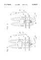
- FIG. 5is a partial cross-sectional view of applicants improved medical intubation apparatus utilizing a magnetically shielded sensor.
- FIG. 6is an enlarged cross-sectional view of the magnetically shielded sensor of the present invention.
- FIG. 7is an enlarged cross-sectional view of a second embodiment of the magnetically shielded sensor of the present invention.
- FIG. 8is an enlarged cross-sectional view of a third embodiment of the magnetically shielded sensor of the present invention.
- FIG. 9is a representation of the operation of applicants invention.
- FIG. 10is another representation of the operation of applicants invention.
- FIG. 1illustrates the feeding tube catheter disclosed in U.S. Pat. No. 5,431,640, Gabriel.
- a feeding tube catheter 10includes a permanent magnet 12 and a radio opaque body portion 14. At the distal end of the catheter 10 a radio opaque tip portion 16 adheres to the end part of the body portion 14.
- a lumen 18 in the body portion 14forms a fluid conducting relation with the internal cavity of the tip portion 16 which contains eyelet apertures 20 spaced along the length of the tip portion 16 for discharging and receiving fluids to the small intestine of the patient.
- the feeding tube catheter 10 of U.S. Pat. No. 5,431,640includes a stylet 26 anchored in a cap 28 and extending along the entire length of the lumen 18.
- the stylet 26adds a desired degree of stiffness and rigidity to the catheter 10 to facilitate placement.
- the cap 28is used for extracting the stylet 26 after the catheter 10 has been placed in the patient.
- the cap 28is fitted to a cavity formed in a fixture 30 joined to the free end of the catheter 10 opposite the tip portion 16.
- An additional duct section 32 having a removable closure cap 32Aprovides access when it is desired to introduce or withdraw fluids from the lumen 18 of the feeding tube catheter 10.
- the feeding tube catheter 10 of the U.S. Pat. No. 5,431,640 patentis designed for manipulation by an external permanent magnet having at least 300 Gauss at a distance of 4 inches from the magnet's pole face.
- the external permanent magnetforms a magnetic coupling with the magnet 12 in the feeding tube catheter 10 so that the attractive force between the external permanent magnet and the magnet 12 (i.e., the traction force) permits medical personnel to advance the tip portion 16 of the catheter through the patient's stomach and into the patient's duodenum by manipulation of the external magnet.
- the position of the external permanent magnet with respect to the catheter magnet 12 at which the traction force is sufficient to advance the catheter tip portion 16is referred to as the traction position.
- FIGS. 2-4the feeding tube catheter 10 illustrated in FIG. 1 has been modified to produce a feeding tube catheter 110.
- a sensor 156is positioned in the tip portion 16 of the catheter 110.
- the sensor 156is a magnetic reed switch which includes reeds 152, 154 sealed in a glass envelope 157.
- Leads 158connect the sensor 156 to a signal generator 160.
- the signal generatorincludes a battery 162 which supplies power to a signal device 164 when the reeds 152, 154 close in response to a magnetic field supplied by an external permanent magnet (FIGS. 3-4).
- the purpose of the sensor 156is to provide a signal when--and only when--the magnet 12 in the distal end of the tip portion 16 is magnetically coupled with an external magnet 34 (FIGS. 3 and 4) sufficiently to create a traction force. Stated another way, the sensor 156 should provide a signal when the external magnet 34 is in the traction position. The signal generator 160 should not provide a signal when the external permanent magnet 34 is not capable of manipulating the tip portion 16 of the feeding tube catheter 110.
- a distance D in FIGS. 3 and 4defines a traction position by indicating the distance at which the external permanent magnet 34 becomes magnetically coupled with the magnet 12 in the distal end portion 150 of the tip portion 16 so that movement of the external permanent magnet 34 produces a corresponding movement of the distal end portion 150 of the feeding tube catheter 110.
- the distance Dwhich generally represents the distance between the interior of the patient's stomach wall 38 and the exterior of the patient's abdominal wall 48, is about 3.5 inches to 5.0 inches.
- the external permanent magnet 34(also referred to herein as the leader magnet) is positioned out of range of the minimum distance required to form a magnetic coupling with the distal end portion 150 sufficient to permit manipulation of the distal end portion 150 by the external permanent magnet 34.
- the distal end portionincludes the permanent magnet 12 (FIG. 2), which is sometimes referred to herein as a follower magnet.
- the signal generator 10illustrated as energizing a light bulb
- the external permanent magnet 34has been actuated although the external permanent magnet 34 is beyond the minimum distance D required for formation of a magnetic coupling of sufficient strength to permit manipulation of the distal end portion 150 (containing the follower magnet 12) in response to movement of the external permanent magnet 34.
- the term traction positionis defined to mean the position of the external permanent magnet 34 (i.e, the leader magnet) from the distal end portion 150 of the feeding tube catheter 110 containing a magnet 12 (i.e., the follower magnet) at which the magnetic coupling between the leader magnet 34 and the follower magnet 12 is sufficient to permit manipulation of the distal end portion 150 by movement of the leader magnet 34.
- the distance Ddefines the traction position.
- the external permanent magnet 34is shown in the traction position, and the sensor 156 (FIG. 2) has actuated the signal generator 160, as shown by the energized light bulb.
- the modified feeding tube catheter 110does not work as intended.
- the signal generator 160is actuated prematurely (FIG. 3) due to the very strong magnetic field associated with the external magnet 34 (the leader magnet).
- the feeding tube catheter 210includes a sensor 256 positioned in the tip portion 16.
- the sensor 256is a high ampere-turn magnetic reed switch which includes relatively stiff reeds 252, 254 sealed in a glass envelope 257.
- Leads 258, 260connect the sensor 256 to a signal generator 160.
- the magnetic reed switch (252, 254, 257)is disposed within a ferrous metal housing 270 having the general shape of a tube closed at one end.
- the ferrous metal housingincludes tubular walls 272 closed at one end to form a thickened end 274.
- the tubular ferrous metal housing 270acts a magnetic shield to prevent premature closure of the reeds 252, 254 by the magnetic field associated with the external permanent magnet 34 (see FIGS. 9 and 10). Specifically, the ferrous metal housing 270 must become saturated before the magnetic field associated with the external permanent magnet 34 affects the reeds 252, 254. Viewed another way, as the external permanent magnet 34 is moved progressively closer to the sensor 256, the ferrous metal housing 270 deflects or redirects the lines of magnetic flux away from the reeds 252, 254 until the applied magnet field (in this case, the magnetic field associated with the external permanent magnet 34) is sufficiently strong to penetrate the magnetic shield associated with the ferrous metal housing 270 and effect closure of the reeds 252, 254.
- the applied magnet fieldin this case, the magnetic field associated with the external permanent magnet 34
- FIGS. 6-8shown therein are three embodiments of the sensor 256 and the ferrous metal housing 270 of the present invention.
- the magnetic reed switchconsisting of reeds 252, 254 sealed in a glass envelope 257, is disposed within the ferrous metal housing 270.
- the leads 258, 260are soldered to the external portions of the reeds 252, 254, and heatshrink 262, 264 is applied as indicated.
- the reed switch assemblyis then placed within the ferrous metal housing 270 and potting compound 276 is used to hold the reed switch and leads in position.
- potting compound 276is used to hold the reed switch and leads in position.
- a ferrous metal housing 270having a diameter of about 0.125 inch, a tubular wall 272 thickness of about 0.0125 inches, and a thickened end 274 of about 0.125 inches at its maximum thickness resulted in actuation of the signal generator 160 only when the external permanent magnet 34 was within 3.5 to 5.0 inches of the magnetic reed switch, the range established by Gabriel for creation of the traction force necessary to permit manipulation of the feeding tube catheter (either 10, 110, or 210) by the external permanent magnet 34.
- the reeds 252, 254closed at a distance of about 12-18 inches between the external permanent magnet and the magnetic reed switch.
- FIG. 7shown therein is another embodiment of the sensor 256 and the ferrous metal housing 270 of the present invention.
- the tubular wall 272Ais about 0.025 inches thick and the ferrous metal housing is about 0.151 inches in diameter.
- the thickened end portion 274Ais about 0.125 inches thick at its maximum.
- FIG. 8shows another embodiment of the sensor 256 and the ferrous metal housing 270 of the present invention.
- the thickness of the tubular wall 272Bis about 0.0125 inches and the thickened end 274B is about 0.125 inches thick at its thickest point.
- the ferrous metal housing 270is annealed to a full soft condition to maximize magnetic permeability.
- FIGS. 9 and 10The operation of the feeding tube catheter 210 is illustrated in FIGS. 9 and 10.
- a distance D in FIGS. 9 and 10defines the traction position, i.e., the distance at which the external permanent magnet 34 becomes magnetically coupled with the magnet 12 in the distal end portion 250 of the tip portion 16 so that movement of the external permanent magnet 34 produces a corresponding movement of the distal end portion 250 of the feeding tube catheter 110.
- the distance Dwhich generally represents the distance between the interior of the patient's stomach wall 38 and the exterior of the patient's abdominal wall 48, is about 3.5 inches to 5.0 inches.
- the external permanent magnet 34(also referred to as the leader magnet) is positioned out of range of the minimum distance required to form a magnetic coupling with the distal end portion 250 sufficient to permit manipulation of the distal end portion 250 by the external permanent magnet 34.
- the distal end portionincludes the permanent magnet 12 (FIGS. 1, 2, and 5), which is sometimes referred to herein as a follower magnet.
- the signal generator 160is not actuated so long as external permanent magnet 34 is beyond the minimum distance D required for formation of a magnetic coupling of sufficient strength to permit manipulation of the distal end portion 250 (containing the follower magnet 12) in response to movement of the external permanent magnet 34.
- the external permanent magnet 34is shown in the traction position, and the sensor 256 (FIG. 2) has actuated the signal generator 160, as shown by the energized light bulb.
- the modified feeding tube catheter 210performs as desired.
- the signal generator 160is not actuated prematurely by the very strong magnetic field associated with the external magnet 34 (the leader magnet).
- the ferrous metal housing 270which acts as a magnetic shield to prevent the reeds 252, 254 from closing prematurely, can be altered to produce a sensor which actuates the signal generator at a particular specified operating distance between the housed magnetic reed switch and the external permanent magnet.
- a relatively thinner tubular wall 272, 272A, 272Bwill result in actuation of the signal generator at a greater operating distance.
- a relatively thinner thickened end 274, 274A, 272Bwill also result in actuation of the signal generator at a greater operating distance. Selection of the magnetic reed switch also affects the operating distance.
- a magnetic reed switch having relatively more flexible reedsresults in actuation of the signal generator at a greater operating distance, whereas a magnetic reed switch have relatively stiffer reeds results effectively reduces the distance at which the signal generator is actuated.
- Single-pole, single-throw (SPST), normally-closed magnetic reed switches (also referred to by those skilled in the art as Form “B” reed switches), single-pole, double-throw (SPDT), and break-before-make reed switches (also referred to by those skilled in the art as Form “C” reed switches)are known in the art and suitable for use in lieu of the magnetic reed switch 16 of FIGS. 5-8. Whether Form A, Form B, or Form C, each type of switch can be shielded in accordance with the present invention as taught herein.
- the present inventionseparate and apart from its application with a feeding tube catheter, is for apparatus involving a magnetic reed switch disposed within a housing for use with a leader magnet and a follower magnet, so that, for a leader magnet having a specified magnetic field strength, the reed switch closes at a specified distance.
- the present inventionwill actuate a signal generator at a distance previously determined to create the traction force necessary for the leader magnet to manipulate the follower magnet.
- the leader magnetcan be used to manipulate the follower magnet to assist in pulling copper wires through hollow walls, in manipulating fiber optic cameras in close environments such as plastic pipes, and, more generally, to create a magnetic guidance path by creating a traction force between a leader magnet and a following magnet.
- the sensor of the present inventionprovides an indication when the leader magnet is in the traction position.
Landscapes
- Health & Medical Sciences (AREA)
- Life Sciences & Earth Sciences (AREA)
- Animal Behavior & Ethology (AREA)
- Veterinary Medicine (AREA)
- Public Health (AREA)
- General Health & Medical Sciences (AREA)
- Engineering & Computer Science (AREA)
- Heart & Thoracic Surgery (AREA)
- Hematology (AREA)
- Biomedical Technology (AREA)
- Anesthesiology (AREA)
- Pulmonology (AREA)
- Biophysics (AREA)
- Media Introduction/Drainage Providing Device (AREA)
- Investigating Or Analyzing Materials By The Use Of Magnetic Means (AREA)
- Soft Magnetic Materials (AREA)
Abstract
Description
Claims (70)
Priority Applications (21)
| Application Number | Priority Date | Filing Date | Title |
|---|---|---|---|
| US09/313,456US6126647A (en) | 1999-05-17 | 1999-05-17 | Magnetically guided catheter with sensor |
| MXPA01011922AMXPA01011922A (en) | 1999-05-17 | 2000-04-05 | Shielded magnetic reed switch. |
| CA002371495ACA2371495A1 (en) | 1999-05-17 | 2000-04-05 | Shielded magnetic reed switch |
| AU40726/00AAU4072600A (en) | 1999-05-17 | 2000-04-05 | Shielded magnetic reed switch |
| PCT/US2000/008997WO2000070914A2 (en) | 1999-05-17 | 2000-04-05 | Shielded magnetic reed switch |
| JP2000619240AJP2003526181A (en) | 1999-05-17 | 2000-04-05 | Shielded magnetic reed switch |
| EP00920144AEP1579729A2 (en) | 1999-05-17 | 2000-04-05 | Shielded magnetic reed switch |
| AU48525/00AAU768072B2 (en) | 1999-05-17 | 2000-05-16 | Magnetically guided catheter with sensor |
| ES00930762TES2269144T3 (en) | 1999-05-17 | 2000-05-16 | MAGNETICALLY GUIDED CATETER WITH SENSOR. |
| IL14653200AIL146532A0 (en) | 1999-05-17 | 2000-05-16 | Magnetically guided catheter with sensor |
| JP2000617963AJP4269009B2 (en) | 1999-05-17 | 2000-05-16 | Magnetically guided catheter with sensor |
| DE60029586TDE60029586T2 (en) | 1999-05-17 | 2000-05-16 | MAGNETIC GUIDED CATHETER WITH SENSOR |
| MXPA01011788AMXPA01011788A (en) | 1999-05-17 | 2000-05-16 | Magnetically guided catheter with sensor. |
| PCT/US2000/013422WO2000069505A1 (en) | 1999-05-17 | 2000-05-16 | Magnetically guided catheter with sensor |
| EP00930762AEP1185328B1 (en) | 1999-05-17 | 2000-05-16 | Magnetically guided catheter with sensor |
| CA002370851ACA2370851C (en) | 1999-05-17 | 2000-05-16 | Magnetically guided catheter with sensor |
| AT00930762TATE333918T1 (en) | 1999-05-17 | 2000-05-16 | MAGNETICALLY GUIDED CATHETER WITH A SENSOR |
| PCT/US2000/013571WO2000070632A1 (en) | 1999-05-17 | 2000-05-17 | Magnetic guide |
| AU51391/00AAU5139100A (en) | 1999-05-17 | 2000-05-17 | Magnetic guide |
| IL146532AIL146532A (en) | 1999-05-17 | 2001-11-15 | Magnetically guided catheter with sensor |
| ZA200110204AZA200110204B (en) | 1999-05-17 | 2001-12-12 | Magnetically guided cathether with sensor. |
Applications Claiming Priority (1)
| Application Number | Priority Date | Filing Date | Title |
|---|---|---|---|
| US09/313,456US6126647A (en) | 1999-05-17 | 1999-05-17 | Magnetically guided catheter with sensor |
Publications (1)
| Publication Number | Publication Date |
|---|---|
| US6126647Atrue US6126647A (en) | 2000-10-03 |
Family
ID=23215763
Family Applications (1)
| Application Number | Title | Priority Date | Filing Date |
|---|---|---|---|
| US09/313,456Expired - LifetimeUS6126647A (en) | 1999-05-17 | 1999-05-17 | Magnetically guided catheter with sensor |
Country Status (12)
| Country | Link |
|---|---|
| US (1) | US6126647A (en) |
| EP (1) | EP1185328B1 (en) |
| JP (1) | JP4269009B2 (en) |
| AT (1) | ATE333918T1 (en) |
| AU (1) | AU768072B2 (en) |
| CA (1) | CA2370851C (en) |
| DE (1) | DE60029586T2 (en) |
| ES (1) | ES2269144T3 (en) |
| IL (2) | IL146532A0 (en) |
| MX (1) | MXPA01011788A (en) |
| WO (1) | WO2000069505A1 (en) |
| ZA (1) | ZA200110204B (en) |
Cited By (77)
| Publication number | Priority date | Publication date | Assignee | Title |
|---|---|---|---|---|
| US6385472B1 (en)* | 1999-09-10 | 2002-05-07 | Stereotaxis, Inc. | Magnetically navigable telescoping catheter and method of navigating telescoping catheter |
| US6542766B2 (en)* | 1999-05-13 | 2003-04-01 | Andrew F. Hall | Medical devices adapted for magnetic navigation with magnetic fields and gradients |
| US20030144590A1 (en)* | 2002-01-29 | 2003-07-31 | Siemens Aktiengesellschaft | Medical examination and/or treatment system |
| US20030176786A1 (en)* | 2002-01-29 | 2003-09-18 | Michael Maschke | Catheter with variable magnetic field generator for catheter guidance in a subject |
| US20040019378A1 (en)* | 2001-04-24 | 2004-01-29 | Hlavka Edwin J. | Method and apparatus for performing catheter-based annuloplasty |
| US20040172046A1 (en)* | 2002-10-21 | 2004-09-02 | Hlavka Edwin J. | Method and apparatus for performing catheter-based annuloplasty using local plications |
| US20040215304A1 (en)* | 2003-04-25 | 2004-10-28 | Kane Michael R. | Method and apparatus for coronary sinus cannulation |
| US20050119687A1 (en)* | 2003-09-08 | 2005-06-02 | Dacey Ralph G.Jr. | Methods of, and materials for, treating vascular defects with magnetically controllable hydrogels |
| US20050119735A1 (en)* | 2002-10-21 | 2005-06-02 | Spence Paul A. | Tissue fastening systems and methods utilizing magnetic guidance |
| US20050125011A1 (en)* | 2001-04-24 | 2005-06-09 | Spence Paul A. | Tissue fastening systems and methods utilizing magnetic guidance |
| US20050137700A1 (en)* | 2003-12-23 | 2005-06-23 | Spence Paul A. | Tissue fastening systems and methods utilizing magnetic guidance |
| US20050161052A1 (en)* | 2002-02-01 | 2005-07-28 | Rezai Ali R. | Method and apparatus for subcutaneously advancing a device between locations |
| US20060069429A1 (en)* | 2001-04-24 | 2006-03-30 | Spence Paul A | Tissue fastening systems and methods utilizing magnetic guidance |
| US20070255086A1 (en)* | 2006-04-26 | 2007-11-01 | Nehls Robert J | Medical Device Including Magnetic Particles |
| US20070276216A1 (en)* | 2004-08-16 | 2007-11-29 | Refael Beyar | Image-Guided Navigation for Catheter-Based Interventions |
| US20080140100A1 (en)* | 2005-03-19 | 2008-06-12 | Michael Gertner | Devices With Integral Magnets and Uses Thereof |
| US20090012517A1 (en)* | 2007-07-03 | 2009-01-08 | Irvine Biomedical, Inc. | Magnetically guided catheter |
| US20090062772A1 (en)* | 2007-08-30 | 2009-03-05 | Syncro Medical Innovations, Inc. | Guided catheter with removable magnetic guide |
| US20090131955A1 (en)* | 2005-09-29 | 2009-05-21 | Corindus Ltd. | Methods and apparatuses for treatment of hollow organs |
| US20090221958A1 (en)* | 2005-05-10 | 2009-09-03 | Rafael Beyar | User interface for remote control catheterization |
| US20090318873A1 (en)* | 2008-06-24 | 2009-12-24 | Cook Incorporated | Medical malecot with magnets |
| US20090318854A1 (en)* | 2008-06-24 | 2009-12-24 | Cook Incorporated | Gastric port system |
| US20100069833A1 (en)* | 2008-05-06 | 2010-03-18 | Corindus Ltd. | Catheter system |
| US20100145147A1 (en)* | 2008-09-02 | 2010-06-10 | Syncro Medical Innovations, Inc. | Magnetic device for guiding catheter and method of use therefor |
| WO2011005903A3 (en)* | 2009-07-09 | 2011-03-31 | Silhouette Medical Inc. | Apparatus for treating medical conditions of hollow anatomical structures |
| WO2011005897A3 (en)* | 2009-07-09 | 2011-03-31 | Silhouette Medical Inc. | Apparatus for treating medical conditions of hollow anatomical structures |
| WO2011005898A3 (en)* | 2009-07-09 | 2011-03-31 | Silhouette Medical Inc. | Apparatus for treating medical conditions of hollow anatomical structures |
| WO2011005902A3 (en)* | 2009-07-09 | 2011-03-31 | Silhouette Medical Inc. | Apparatus for treating medical conditions of hollow anatomical structures |
| WO2011005901A3 (en)* | 2009-07-09 | 2011-04-28 | Silhouette Medical Inc. | Apparatus for treating medical conditions of hollow anatomical structures |
| US20110106019A1 (en)* | 2007-11-21 | 2011-05-05 | Piezo Resonance Innovations, Inc. | Devices for clearing blockages in in-situ artificial lumens |
| US20110144658A1 (en)* | 2008-08-29 | 2011-06-16 | Corindus Inc. | Catheter simulation and assistance system |
| US20110152882A1 (en)* | 2008-08-29 | 2011-06-23 | Corindus Inc. | Catheter control system and graphical user interface |
| US20110238082A1 (en)* | 2008-12-12 | 2011-09-29 | Corindus Inc. | Remote catheter procedure system |
| US20120017923A1 (en)* | 2010-07-26 | 2012-01-26 | Lior Sobe | Removable Navigation System and Method for a Medical Device |
| US20120035460A1 (en)* | 2010-08-05 | 2012-02-09 | Stangenes Todd R | Movable magnet for magnetically guided catheter |
| US20130218076A1 (en)* | 2007-05-23 | 2013-08-22 | Biosense Webster, Inc. | Magnetically guided catheter with concentric needle port |
| US8715280B2 (en) | 2010-08-04 | 2014-05-06 | St. Jude Medical, Atrial Fibrillation Division, Inc. | Magnetically guided catheters |
| US8734440B2 (en) | 2007-07-03 | 2014-05-27 | St. Jude Medical, Atrial Fibrillation Division, Inc. | Magnetically guided catheter |
| EP2745828A1 (en) | 2012-12-20 | 2014-06-25 | Sabry Gabriel | Feeding tube with inflatable balloon component |
| US8790297B2 (en) | 2009-03-18 | 2014-07-29 | Corindus, Inc. | Remote catheter system with steerable catheter |
| US20140275805A1 (en)* | 2013-03-15 | 2014-09-18 | Applied Medical Research | Bridle Catheter With Illuminating End |
| US8845723B2 (en) | 2007-03-13 | 2014-09-30 | Mitralign, Inc. | Systems and methods for introducing elements into tissue |
| US8864822B2 (en) | 2003-12-23 | 2014-10-21 | Mitralign, Inc. | Devices and methods for introducing elements into tissue |
| US8876819B2 (en) | 2010-08-04 | 2014-11-04 | St. Jude Medical, Atrial Fibrillation Division, Inc. | Magnetically guided catheters |
| US8911461B2 (en) | 2007-03-13 | 2014-12-16 | Mitralign, Inc. | Suture cutter and method of cutting suture |
| US8945118B2 (en) | 2010-08-04 | 2015-02-03 | St. Jude Medical, Atrial Fibrillation Division, Inc. | Catheter with flexible tether and introducer for a catheter |
| US8951286B2 (en) | 2005-07-05 | 2015-02-10 | Mitralign, Inc. | Tissue anchor and anchoring system |
| US20150196752A1 (en)* | 2012-08-10 | 2015-07-16 | Intermountain Invention Managment, Llc | Epicardial lead placement apparatus, systems, and methods |
| US9220568B2 (en) | 2009-10-12 | 2015-12-29 | Corindus Inc. | Catheter system with percutaneous device movement algorithm |
| US9339285B2 (en) | 2013-03-12 | 2016-05-17 | Levita Magnetics International Corp. | Grasper with magnetically-controlled positioning |
| US9358112B2 (en) | 2001-04-24 | 2016-06-07 | Mitralign, Inc. | Method and apparatus for catheter-based annuloplasty using local plications |
| US20160158111A1 (en)* | 2011-07-17 | 2016-06-09 | Nutriseal L.P. | Nasogastric tube |
| US9833293B2 (en) | 2010-09-17 | 2017-12-05 | Corindus, Inc. | Robotic catheter system |
| US9844391B2 (en) | 2009-02-06 | 2017-12-19 | Levita Magnetics International Corp. | Remote traction and guidance system for mini-invasive surgery |
| US9962229B2 (en) | 2009-10-12 | 2018-05-08 | Corindus, Inc. | System and method for navigating a guide wire |
| US10010370B2 (en) | 2013-03-14 | 2018-07-03 | Levita Magnetics International Corp. | Magnetic control assemblies and systems therefor |
| CN108815680A (en)* | 2018-04-17 | 2018-11-16 | 杨延辉 | A kind of laparoscope direct-view is lower to guide stomach tube/jejunal nutrient canal placement location device |
| US10219778B2 (en) | 2013-04-22 | 2019-03-05 | University Of Maryland, Baltimore | Coaptation ultrasound devices and methods of use |
| IT201700113355A1 (en)* | 2017-10-09 | 2019-04-09 | Fitre S P A | MAGNETIC POSITION SENSOR |
| US10376447B2 (en) | 2015-02-02 | 2019-08-13 | Envizion Medical Ltd. | Enteral feeding system with controlled reflux preventive vacuum sealing |
| US10537348B2 (en) | 2014-01-21 | 2020-01-21 | Levita Magnetics International Corp. | Laparoscopic graspers and systems therefor |
| US10646406B2 (en) | 2011-07-17 | 2020-05-12 | Envizion Medical Ltd. | Nasogastric tube |
| US10695269B2 (en) | 2014-08-14 | 2020-06-30 | Envizion Medical Ltd. | Nasogastric tube |
| WO2020223805A1 (en)* | 2019-05-06 | 2020-11-12 | Bles Biochemicals Incorporated | Feeding tube with integrated stylet |
| US10905511B2 (en) | 2015-04-13 | 2021-02-02 | Levita Magnetics International Corp. | Grasper with magnetically-controlled positioning |
| US10918373B2 (en) | 2013-08-31 | 2021-02-16 | Edwards Lifesciences Corporation | Devices and methods for locating and implanting tissue anchors at mitral valve commissure |
| US11020137B2 (en) | 2017-03-20 | 2021-06-01 | Levita Magnetics International Corp. | Directable traction systems and methods |
| WO2021216492A1 (en) | 2020-04-20 | 2021-10-28 | Syncro Medical Innovations, Inc. | Feeding tube with inflatable balloon component and at least one of a carbon dioxide sampling line and a suction tube component |
| US11246658B2 (en) | 2016-10-04 | 2022-02-15 | St. Jude Medical, Cardiology Division, Inc. | Ablation catheter tip |
| US11259838B2 (en) | 2016-04-05 | 2022-03-01 | University Of Maryland, Baltimore | Method and apparatus for coaptive ultrasound gastrostomy |
| US11350986B2 (en) | 2015-03-31 | 2022-06-07 | St. Jude Medical, Cardiology Division, Inc. | High-thermal-sensitivity ablation catheters and catheter tips |
| US11583354B2 (en) | 2015-04-13 | 2023-02-21 | Levita Magnetics International Corp. | Retractor systems, devices, and methods for use |
| US11612546B2 (en) | 2018-04-27 | 2023-03-28 | CoapTech, Inc. | Systems, apparatus, and methods for placing a guidewire for a gastrostomy tube |
| US11660190B2 (en) | 2007-03-13 | 2023-05-30 | Edwards Lifesciences Corporation | Tissue anchors, systems and methods, and devices |
| US20240023965A1 (en)* | 2020-12-14 | 2024-01-25 | The Regents Of The University Of California | Magnetic positioning/deployment and retrieval system |
| US11918314B2 (en) | 2009-10-12 | 2024-03-05 | Corindus, Inc. | System and method for navigating a guide wire |
| US12262971B2 (en) | 2016-01-08 | 2025-04-01 | Levita Magnetics International Corp. | One-operator surgical system and methods of use |
Families Citing this family (1)
| Publication number | Priority date | Publication date | Assignee | Title |
|---|---|---|---|---|
| CA2555196A1 (en)* | 2004-02-20 | 2005-09-09 | Point Guard Medical, Incorporated | Needle guide |
Citations (4)
| Publication number | Priority date | Publication date | Assignee | Title |
|---|---|---|---|---|
| US4077412A (en)* | 1974-12-13 | 1978-03-07 | Moossun Mohamed H | Stomach intubation and catheter placement system |
| US4364377A (en)* | 1979-02-02 | 1982-12-21 | Walker Scientific, Inc. | Magnetic field hemostasis |
| US5176618A (en)* | 1989-08-10 | 1993-01-05 | George Freedman | System for preventing closure of passageways |
| US5431640A (en)* | 1994-11-09 | 1995-07-11 | The Medical Center Of Central Georgia | Method and apparatus for duodenal intubation of a patient |
Family Cites Families (4)
| Publication number | Priority date | Publication date | Assignee | Title |
|---|---|---|---|---|
| US3043309A (en)* | 1959-09-29 | 1962-07-10 | Avco Corp | Method of performing intestinal intubation |
| US5257636A (en)* | 1991-04-02 | 1993-11-02 | Steven J. White | Apparatus for determining position of an endothracheal tube |
| ES2231887T3 (en)* | 1996-09-17 | 2005-05-16 | Biosense Webster, Inc. | SYSTEM TO CONFIRM THE POSITION WITH LEARNING AND TEST FUNCTIONS. |
| CA2331129C (en)* | 1998-05-05 | 2007-04-10 | Sabry Gabriel | Method and apparatus for intubation of a patient |
- 1999
- 1999-05-17USUS09/313,456patent/US6126647A/ennot_activeExpired - Lifetime
- 2000
- 2000-05-16ILIL14653200Apatent/IL146532A0/enactiveIP Right Grant
- 2000-05-16ESES00930762Tpatent/ES2269144T3/ennot_activeExpired - Lifetime
- 2000-05-16AUAU48525/00Apatent/AU768072B2/ennot_activeCeased
- 2000-05-16MXMXPA01011788Apatent/MXPA01011788A/enactiveIP Right Grant
- 2000-05-16JPJP2000617963Apatent/JP4269009B2/ennot_activeExpired - Fee Related
- 2000-05-16CACA002370851Apatent/CA2370851C/ennot_activeExpired - Fee Related
- 2000-05-16WOPCT/US2000/013422patent/WO2000069505A1/enactiveIP Right Grant
- 2000-05-16DEDE60029586Tpatent/DE60029586T2/ennot_activeExpired - Lifetime
- 2000-05-16EPEP00930762Apatent/EP1185328B1/ennot_activeExpired - Lifetime
- 2000-05-16ATAT00930762Tpatent/ATE333918T1/ennot_activeIP Right Cessation
- 2001
- 2001-11-15ILIL146532Apatent/IL146532A/ennot_activeIP Right Cessation
- 2001-12-12ZAZA200110204Apatent/ZA200110204B/enunknown
Patent Citations (4)
| Publication number | Priority date | Publication date | Assignee | Title |
|---|---|---|---|---|
| US4077412A (en)* | 1974-12-13 | 1978-03-07 | Moossun Mohamed H | Stomach intubation and catheter placement system |
| US4364377A (en)* | 1979-02-02 | 1982-12-21 | Walker Scientific, Inc. | Magnetic field hemostasis |
| US5176618A (en)* | 1989-08-10 | 1993-01-05 | George Freedman | System for preventing closure of passageways |
| US5431640A (en)* | 1994-11-09 | 1995-07-11 | The Medical Center Of Central Georgia | Method and apparatus for duodenal intubation of a patient |
Cited By (154)
| Publication number | Priority date | Publication date | Assignee | Title |
|---|---|---|---|---|
| US7211082B2 (en) | 1998-09-11 | 2007-05-01 | Stereotaxis, Inc. | Magnetically navigable telescoping catheter and method of navigating telescoping catheter |
| US20040158142A1 (en)* | 1998-09-11 | 2004-08-12 | Hall Andrew F. | Magnetically navigable telescoping catheter and method of navigating telescoping catheter |
| US6542766B2 (en)* | 1999-05-13 | 2003-04-01 | Andrew F. Hall | Medical devices adapted for magnetic navigation with magnetic fields and gradients |
| US6385472B1 (en)* | 1999-09-10 | 2002-05-07 | Stereotaxis, Inc. | Magnetically navigable telescoping catheter and method of navigating telescoping catheter |
| US20060069429A1 (en)* | 2001-04-24 | 2006-03-30 | Spence Paul A | Tissue fastening systems and methods utilizing magnetic guidance |
| US20050125011A1 (en)* | 2001-04-24 | 2005-06-09 | Spence Paul A. | Tissue fastening systems and methods utilizing magnetic guidance |
| US20040019378A1 (en)* | 2001-04-24 | 2004-01-29 | Hlavka Edwin J. | Method and apparatus for performing catheter-based annuloplasty |
| US9358112B2 (en) | 2001-04-24 | 2016-06-07 | Mitralign, Inc. | Method and apparatus for catheter-based annuloplasty using local plications |
| US20030176786A1 (en)* | 2002-01-29 | 2003-09-18 | Michael Maschke | Catheter with variable magnetic field generator for catheter guidance in a subject |
| US7686767B2 (en)* | 2002-01-29 | 2010-03-30 | Siemens Aktiengesellschaft | Catheter with variable magnetic field generator for catheter guidance in a subject |
| US6772001B2 (en)* | 2002-01-29 | 2004-08-03 | Siemens Aktiengesellschaft | Medical examination and/or treatment system |
| US20030144590A1 (en)* | 2002-01-29 | 2003-07-31 | Siemens Aktiengesellschaft | Medical examination and/or treatment system |
| US7833174B2 (en)* | 2002-02-01 | 2010-11-16 | The Cleveland Clinic Foundation | Method and apparatus for subcutaneously advancing a device between locations |
| US20050161052A1 (en)* | 2002-02-01 | 2005-07-28 | Rezai Ali R. | Method and apparatus for subcutaneously advancing a device between locations |
| US20050119735A1 (en)* | 2002-10-21 | 2005-06-02 | Spence Paul A. | Tissue fastening systems and methods utilizing magnetic guidance |
| US10028833B2 (en) | 2002-10-21 | 2018-07-24 | Mitralign, Inc. | Tissue fastening systems and methods utilizing magnetic guidance |
| US8460371B2 (en) | 2002-10-21 | 2013-06-11 | Mitralign, Inc. | Method and apparatus for performing catheter-based annuloplasty using local plications |
| US20050119734A1 (en)* | 2002-10-21 | 2005-06-02 | Spence Paul A. | Tissue fastening systems and methods utilizing magnetic guidance |
| US8979923B2 (en) | 2002-10-21 | 2015-03-17 | Mitralign, Inc. | Tissue fastening systems and methods utilizing magnetic guidance |
| US20040172046A1 (en)* | 2002-10-21 | 2004-09-02 | Hlavka Edwin J. | Method and apparatus for performing catheter-based annuloplasty using local plications |
| US20040215304A1 (en)* | 2003-04-25 | 2004-10-28 | Kane Michael R. | Method and apparatus for coronary sinus cannulation |
| US6985776B2 (en) | 2003-04-25 | 2006-01-10 | Medtronic, Inc. | Method and apparatus for coronary sinus cannulation |
| US20050119687A1 (en)* | 2003-09-08 | 2005-06-02 | Dacey Ralph G.Jr. | Methods of, and materials for, treating vascular defects with magnetically controllable hydrogels |
| US7166127B2 (en) | 2003-12-23 | 2007-01-23 | Mitralign, Inc. | Tissue fastening systems and methods utilizing magnetic guidance |
| US7431726B2 (en) | 2003-12-23 | 2008-10-07 | Mitralign, Inc. | Tissue fastening systems and methods utilizing magnetic guidance |
| US20070080188A1 (en)* | 2003-12-23 | 2007-04-12 | Mitralign, Inc. | Tissue fastening systems and methods |
| US8142493B2 (en) | 2003-12-23 | 2012-03-27 | Mitralign, Inc. | Method of heart valve repair |
| US20050137700A1 (en)* | 2003-12-23 | 2005-06-23 | Spence Paul A. | Tissue fastening systems and methods utilizing magnetic guidance |
| US8864822B2 (en) | 2003-12-23 | 2014-10-21 | Mitralign, Inc. | Devices and methods for introducing elements into tissue |
| US20050267571A1 (en)* | 2003-12-23 | 2005-12-01 | Spence Paul A | Tissue fastening systems and methods utilizing magnetic guidance |
| US8600477B2 (en) | 2004-08-16 | 2013-12-03 | Corinduc, Inc. | Image-guided navigation for catheter-based interventions |
| US20070276216A1 (en)* | 2004-08-16 | 2007-11-29 | Refael Beyar | Image-Guided Navigation for Catheter-Based Interventions |
| US7712470B2 (en)* | 2005-03-19 | 2010-05-11 | Michael Gertner | Devices with integral magnets and uses thereof |
| US20080140100A1 (en)* | 2005-03-19 | 2008-06-12 | Michael Gertner | Devices With Integral Magnets and Uses Thereof |
| US20090221958A1 (en)* | 2005-05-10 | 2009-09-03 | Rafael Beyar | User interface for remote control catheterization |
| US8257302B2 (en) | 2005-05-10 | 2012-09-04 | Corindus, Inc. | User interface for remote control catheterization |
| US10695046B2 (en) | 2005-07-05 | 2020-06-30 | Edwards Lifesciences Corporation | Tissue anchor and anchoring system |
| US8951286B2 (en) | 2005-07-05 | 2015-02-10 | Mitralign, Inc. | Tissue anchor and anchoring system |
| US9259218B2 (en) | 2005-07-05 | 2016-02-16 | Mitralign, Inc. | Tissue anchor and anchoring system |
| US9814454B2 (en) | 2005-07-05 | 2017-11-14 | Mitralign, Inc. | Tissue anchor and anchoring system |
| US8951285B2 (en) | 2005-07-05 | 2015-02-10 | Mitralign, Inc. | Tissue anchor, anchoring system and methods of using the same |
| US20090131955A1 (en)* | 2005-09-29 | 2009-05-21 | Corindus Ltd. | Methods and apparatuses for treatment of hollow organs |
| US20070255086A1 (en)* | 2006-04-26 | 2007-11-01 | Nehls Robert J | Medical Device Including Magnetic Particles |
| US11660190B2 (en) | 2007-03-13 | 2023-05-30 | Edwards Lifesciences Corporation | Tissue anchors, systems and methods, and devices |
| US8911461B2 (en) | 2007-03-13 | 2014-12-16 | Mitralign, Inc. | Suture cutter and method of cutting suture |
| US8845723B2 (en) | 2007-03-13 | 2014-09-30 | Mitralign, Inc. | Systems and methods for introducing elements into tissue |
| US9358111B2 (en) | 2007-03-13 | 2016-06-07 | Mitralign, Inc. | Tissue anchors, systems and methods, and devices |
| US9750608B2 (en) | 2007-03-13 | 2017-09-05 | Mitralign, Inc. | Systems and methods for introducing elements into tissue |
| US10695535B2 (en) | 2007-05-23 | 2020-06-30 | Biosense Webster, Inc. | Magnetically guided catheter with concentric needle port |
| US9919131B2 (en) | 2007-05-23 | 2018-03-20 | Biosense Webster, Inc. | Magnetically guided catheter with concentric needle port |
| US9017283B2 (en)* | 2007-05-23 | 2015-04-28 | Biosense Webster, Inc. | Magnetically guided catheter with concentric needle port |
| US20130218076A1 (en)* | 2007-05-23 | 2013-08-22 | Biosense Webster, Inc. | Magnetically guided catheter with concentric needle port |
| US10039598B2 (en) | 2007-07-03 | 2018-08-07 | St. Jude Medical, Atrial Fibrillation Division, Inc. | Magnetically guided catheter |
| US8206404B2 (en) | 2007-07-03 | 2012-06-26 | St. Jude Medical, Atrial Fibrillation Division, Inc. | Magnetically guided catheter |
| US20090012517A1 (en)* | 2007-07-03 | 2009-01-08 | Irvine Biomedical, Inc. | Magnetically guided catheter |
| US8734440B2 (en) | 2007-07-03 | 2014-05-27 | St. Jude Medical, Atrial Fibrillation Division, Inc. | Magnetically guided catheter |
| US8715279B2 (en) | 2007-07-03 | 2014-05-06 | St. Jude Medical, Atrial Fibrillation Division, Inc. | Magnetically guided catheter |
| AU2008292840B2 (en)* | 2007-08-30 | 2011-09-15 | Syncro Medical Innovations, Inc. | Guided catheter with removable magnetic guide |
| US20090062772A1 (en)* | 2007-08-30 | 2009-03-05 | Syncro Medical Innovations, Inc. | Guided catheter with removable magnetic guide |
| US8262645B2 (en) | 2007-11-21 | 2012-09-11 | Actuated Medical, Inc. | Devices for clearing blockages in in-situ artificial lumens |
| US20110106019A1 (en)* | 2007-11-21 | 2011-05-05 | Piezo Resonance Innovations, Inc. | Devices for clearing blockages in in-situ artificial lumens |
| US7887549B2 (en) | 2008-05-06 | 2011-02-15 | Corindus Inc. | Catheter system |
| US9095681B2 (en) | 2008-05-06 | 2015-08-04 | Corindus Inc. | Catheter system |
| US20100076308A1 (en)* | 2008-05-06 | 2010-03-25 | Corindus Ltd. | Catheter system |
| US20100076309A1 (en)* | 2008-05-06 | 2010-03-25 | Corindus Ltd. | Catheter system |
| US8480618B2 (en) | 2008-05-06 | 2013-07-09 | Corindus Inc. | Catheter system |
| US11717645B2 (en) | 2008-05-06 | 2023-08-08 | Corindus, Inc. | Robotic catheter system |
| US9623209B2 (en) | 2008-05-06 | 2017-04-18 | Corindus, Inc. | Robotic catheter system |
| US8828021B2 (en) | 2008-05-06 | 2014-09-09 | Corindus, Inc. | Catheter system |
| US20100076310A1 (en)* | 2008-05-06 | 2010-03-25 | Corindus Ltd. | Catheter system |
| US9402977B2 (en) | 2008-05-06 | 2016-08-02 | Corindus Inc. | Catheter system |
| USD680645S1 (en) | 2008-05-06 | 2013-04-23 | Corindus Inc. | Catheter system cassette |
| US10987491B2 (en) | 2008-05-06 | 2021-04-27 | Corindus, Inc. | Robotic catheter system |
| US10342953B2 (en) | 2008-05-06 | 2019-07-09 | Corindus, Inc. | Robotic catheter system |
| US9168356B2 (en) | 2008-05-06 | 2015-10-27 | Corindus Inc. | Robotic catheter system |
| US20100069833A1 (en)* | 2008-05-06 | 2010-03-18 | Corindus Ltd. | Catheter system |
| US20090318873A1 (en)* | 2008-06-24 | 2009-12-24 | Cook Incorporated | Medical malecot with magnets |
| US20090318854A1 (en)* | 2008-06-24 | 2009-12-24 | Cook Incorporated | Gastric port system |
| US9107810B2 (en) | 2008-06-24 | 2015-08-18 | Cook Medical Technologies Llc | Gastric port system |
| US10085921B2 (en) | 2008-06-24 | 2018-10-02 | Cook Medical Technologies Llc | Gastric port system |
| US20110152882A1 (en)* | 2008-08-29 | 2011-06-23 | Corindus Inc. | Catheter control system and graphical user interface |
| US20110144658A1 (en)* | 2008-08-29 | 2011-06-16 | Corindus Inc. | Catheter simulation and assistance system |
| US8694157B2 (en) | 2008-08-29 | 2014-04-08 | Corindus, Inc. | Catheter control system and graphical user interface |
| US20100145147A1 (en)* | 2008-09-02 | 2010-06-10 | Syncro Medical Innovations, Inc. | Magnetic device for guiding catheter and method of use therefor |
| US12171955B2 (en) | 2008-12-12 | 2024-12-24 | Siemens Healthineers Endovascular Robotics Inc | Remote catheter procedure system |
| US10561821B2 (en) | 2008-12-12 | 2020-02-18 | Corindus, Inc. | Remote catheter procedure system |
| US20110238082A1 (en)* | 2008-12-12 | 2011-09-29 | Corindus Inc. | Remote catheter procedure system |
| US9545497B2 (en) | 2008-12-12 | 2017-01-17 | Corindus, Inc. | Remote catheter procedure system |
| US9974546B2 (en) | 2009-02-06 | 2018-05-22 | Levita Magnetics International Corp. | Remote traction and guidance system for mini-invasive surgery |
| US9844391B2 (en) | 2009-02-06 | 2017-12-19 | Levita Magnetics International Corp. | Remote traction and guidance system for mini-invasive surgery |
| US8790297B2 (en) | 2009-03-18 | 2014-07-29 | Corindus, Inc. | Remote catheter system with steerable catheter |
| WO2011005901A3 (en)* | 2009-07-09 | 2011-04-28 | Silhouette Medical Inc. | Apparatus for treating medical conditions of hollow anatomical structures |
| WO2011005898A3 (en)* | 2009-07-09 | 2011-03-31 | Silhouette Medical Inc. | Apparatus for treating medical conditions of hollow anatomical structures |
| WO2011005897A3 (en)* | 2009-07-09 | 2011-03-31 | Silhouette Medical Inc. | Apparatus for treating medical conditions of hollow anatomical structures |
| WO2011005902A3 (en)* | 2009-07-09 | 2011-03-31 | Silhouette Medical Inc. | Apparatus for treating medical conditions of hollow anatomical structures |
| WO2011005903A3 (en)* | 2009-07-09 | 2011-03-31 | Silhouette Medical Inc. | Apparatus for treating medical conditions of hollow anatomical structures |
| US10881474B2 (en) | 2009-10-12 | 2021-01-05 | Corindus, Inc. | System and method for navigating a guide wire |
| US9220568B2 (en) | 2009-10-12 | 2015-12-29 | Corindus Inc. | Catheter system with percutaneous device movement algorithm |
| US11696808B2 (en) | 2009-10-12 | 2023-07-11 | Corindus, Inc. | System and method for navigating a guide wire |
| US9962229B2 (en) | 2009-10-12 | 2018-05-08 | Corindus, Inc. | System and method for navigating a guide wire |
| US11918314B2 (en) | 2009-10-12 | 2024-03-05 | Corindus, Inc. | System and method for navigating a guide wire |
| US10390889B2 (en)* | 2010-07-26 | 2019-08-27 | St Jude Medical International Holding S.Á R.L. | Removable navigation system and method for a medical device |
| US20120017923A1 (en)* | 2010-07-26 | 2012-01-26 | Lior Sobe | Removable Navigation System and Method for a Medical Device |
| US10052152B2 (en) | 2010-08-04 | 2018-08-21 | St. Jude Medical, Atrial Fibrillation Division, Inc. | Catheter electrode assembly |
| US8876819B2 (en) | 2010-08-04 | 2014-11-04 | St. Jude Medical, Atrial Fibrillation Division, Inc. | Magnetically guided catheters |
| US9545498B2 (en) | 2010-08-04 | 2017-01-17 | St. Jude Medical, Atrial Fibrillation Division, Inc. | Magnetically guided catheters |
| US8945118B2 (en) | 2010-08-04 | 2015-02-03 | St. Jude Medical, Atrial Fibrillation Division, Inc. | Catheter with flexible tether and introducer for a catheter |
| US9023033B2 (en) | 2010-08-04 | 2015-05-05 | St. Jude Medical, Atrial Fibrillation Division, Inc. | Magnetically guided catheters |
| US8715280B2 (en) | 2010-08-04 | 2014-05-06 | St. Jude Medical, Atrial Fibrillation Division, Inc. | Magnetically guided catheters |
| US20120035460A1 (en)* | 2010-08-05 | 2012-02-09 | Stangenes Todd R | Movable magnet for magnetically guided catheter |
| US9463302B2 (en) | 2010-08-05 | 2016-10-11 | St. Jude Medical, Atrial Fibrillation Division, Inc. | Movable magnet for magnetically guided catheter |
| US8532743B2 (en)* | 2010-08-05 | 2013-09-10 | St. Jude Medical, Atrial Fibrillation Division, Inc. | Movable magnet for magnetically guided catheter |
| US9833293B2 (en) | 2010-09-17 | 2017-12-05 | Corindus, Inc. | Robotic catheter system |
| US20160158111A1 (en)* | 2011-07-17 | 2016-06-09 | Nutriseal L.P. | Nasogastric tube |
| US10350145B2 (en)* | 2011-07-17 | 2019-07-16 | Envizion Medical Ltd. | Nasogastric tube |
| US10646406B2 (en) | 2011-07-17 | 2020-05-12 | Envizion Medical Ltd. | Nasogastric tube |
| US20150196752A1 (en)* | 2012-08-10 | 2015-07-16 | Intermountain Invention Managment, Llc | Epicardial lead placement apparatus, systems, and methods |
| EP2745828A1 (en) | 2012-12-20 | 2014-06-25 | Sabry Gabriel | Feeding tube with inflatable balloon component |
| US9339285B2 (en) | 2013-03-12 | 2016-05-17 | Levita Magnetics International Corp. | Grasper with magnetically-controlled positioning |
| US10130381B2 (en) | 2013-03-12 | 2018-11-20 | Levita Magnetics International Corp. | Grasper with magnetically-controlled positioning |
| US12329402B2 (en) | 2013-03-12 | 2025-06-17 | Levita Magnetics International Corp. | Grasper with magnetically-controlled positioning |
| US11357525B2 (en) | 2013-03-12 | 2022-06-14 | Levita Magnetics International Corp. | Grasper with magnetically-controlled positioning |
| US10010370B2 (en) | 2013-03-14 | 2018-07-03 | Levita Magnetics International Corp. | Magnetic control assemblies and systems therefor |
| US20140275805A1 (en)* | 2013-03-15 | 2014-09-18 | Applied Medical Research | Bridle Catheter With Illuminating End |
| WO2014150416A1 (en)* | 2013-03-15 | 2014-09-25 | Applied Medical Research | Bridle catheter with illuminating end |
| US9561158B2 (en)* | 2013-03-15 | 2017-02-07 | Applied Medical Technology, Inc. | Bridle catheter with illuminating end |
| US10383595B2 (en) | 2013-04-22 | 2019-08-20 | University Of Maryland, Baltimore | Coaptation ultrasound devices and methods of use |
| US10219778B2 (en) | 2013-04-22 | 2019-03-05 | University Of Maryland, Baltimore | Coaptation ultrasound devices and methods of use |
| US11986340B2 (en) | 2013-04-22 | 2024-05-21 | University Of Maryland, Baltimore | Coaptation ultrasound devices and methods of use |
| US10918373B2 (en) | 2013-08-31 | 2021-02-16 | Edwards Lifesciences Corporation | Devices and methods for locating and implanting tissue anchors at mitral valve commissure |
| US10537348B2 (en) | 2014-01-21 | 2020-01-21 | Levita Magnetics International Corp. | Laparoscopic graspers and systems therefor |
| US12171433B2 (en) | 2014-01-21 | 2024-12-24 | Levita Magnetics International Corp. | Laparoscopic graspers and systems therefor |
| US11730476B2 (en) | 2014-01-21 | 2023-08-22 | Levita Magnetics International Corp. | Laparoscopic graspers and systems therefor |
| US10695269B2 (en) | 2014-08-14 | 2020-06-30 | Envizion Medical Ltd. | Nasogastric tube |
| US10376447B2 (en) | 2015-02-02 | 2019-08-13 | Envizion Medical Ltd. | Enteral feeding system with controlled reflux preventive vacuum sealing |
| US11350986B2 (en) | 2015-03-31 | 2022-06-07 | St. Jude Medical, Cardiology Division, Inc. | High-thermal-sensitivity ablation catheters and catheter tips |
| US11419674B2 (en) | 2015-03-31 | 2022-08-23 | St. Jude Medical, Cardiology Division, Inc. | Methods and devices for delivering pulsed RF energy during catheter ablation |
| US11583354B2 (en) | 2015-04-13 | 2023-02-21 | Levita Magnetics International Corp. | Retractor systems, devices, and methods for use |
| US11751965B2 (en) | 2015-04-13 | 2023-09-12 | Levita Magnetics International Corp. | Grasper with magnetically-controlled positioning |
| US12357407B2 (en) | 2015-04-13 | 2025-07-15 | Levita Magnetics International Corp. | Grasper with magnetically-controlled positioning |
| US10905511B2 (en) | 2015-04-13 | 2021-02-02 | Levita Magnetics International Corp. | Grasper with magnetically-controlled positioning |
| US12262971B2 (en) | 2016-01-08 | 2025-04-01 | Levita Magnetics International Corp. | One-operator surgical system and methods of use |
| US12161363B2 (en) | 2016-04-05 | 2024-12-10 | University Of Maryland, Baltimore | Method and apparatus for coaptive ultrasound gastrostomy |
| US11259838B2 (en) | 2016-04-05 | 2022-03-01 | University Of Maryland, Baltimore | Method and apparatus for coaptive ultrasound gastrostomy |
| US11246658B2 (en) | 2016-10-04 | 2022-02-15 | St. Jude Medical, Cardiology Division, Inc. | Ablation catheter tip |
| US11020137B2 (en) | 2017-03-20 | 2021-06-01 | Levita Magnetics International Corp. | Directable traction systems and methods |
| US12185962B2 (en) | 2017-03-20 | 2025-01-07 | Levita Magnetics International Corp. | Directable traction systems and methods |
| IT201700113355A1 (en)* | 2017-10-09 | 2019-04-09 | Fitre S P A | MAGNETIC POSITION SENSOR |
| CN108815680A (en)* | 2018-04-17 | 2018-11-16 | 杨延辉 | A kind of laparoscope direct-view is lower to guide stomach tube/jejunal nutrient canal placement location device |
| US11612546B2 (en) | 2018-04-27 | 2023-03-28 | CoapTech, Inc. | Systems, apparatus, and methods for placing a guidewire for a gastrostomy tube |
| WO2020223805A1 (en)* | 2019-05-06 | 2020-11-12 | Bles Biochemicals Incorporated | Feeding tube with integrated stylet |
| WO2021216492A1 (en) | 2020-04-20 | 2021-10-28 | Syncro Medical Innovations, Inc. | Feeding tube with inflatable balloon component and at least one of a carbon dioxide sampling line and a suction tube component |
| US20240023965A1 (en)* | 2020-12-14 | 2024-01-25 | The Regents Of The University Of California | Magnetic positioning/deployment and retrieval system |
| US12408921B2 (en)* | 2020-12-14 | 2025-09-09 | The Regents Of The University Of California | Magnetic positioning/deployment and retrieval system |
Also Published As
| Publication number | Publication date |
|---|---|
| ATE333918T1 (en) | 2006-08-15 |
| IL146532A0 (en) | 2002-07-25 |
| WO2000069505A1 (en) | 2000-11-23 |
| JP2004506453A (en) | 2004-03-04 |
| DE60029586T2 (en) | 2007-07-26 |
| DE60029586D1 (en) | 2006-09-07 |
| AU4852500A (en) | 2000-12-05 |
| EP1185328B1 (en) | 2006-07-26 |
| EP1185328A1 (en) | 2002-03-13 |
| JP4269009B2 (en) | 2009-05-27 |
| ES2269144T3 (en) | 2007-04-01 |
| AU768072B2 (en) | 2003-12-04 |
| EP1185328A4 (en) | 2002-08-07 |
| CA2370851C (en) | 2005-03-08 |
| IL146532A (en) | 2006-12-10 |
| ZA200110204B (en) | 2003-07-30 |
| CA2370851A1 (en) | 2000-11-23 |
| MXPA01011788A (en) | 2003-08-19 |
Similar Documents
| Publication | Publication Date | Title |
|---|---|---|
| US6126647A (en) | Magnetically guided catheter with sensor | |
| US5431640A (en) | Method and apparatus for duodenal intubation of a patient | |
| EP2192885B1 (en) | Guided catheter with removable magnetic guide | |
| US9713578B2 (en) | Feeding tube with inflatable balloon component | |
| US6190330B1 (en) | Endoscopic location and vacuum assembly and method | |
| US20160287827A1 (en) | System and method for determining position of a medical device | |
| WO1999023934A3 (en) | Articulated magnetic guidance systems and devices and methods for magnetically-assisted surgery | |
| EP0655223A3 (en) | Device for closing an incision. | |
| US11986411B2 (en) | Devices and methods for treatment of body lumens | |
| CA2257947A1 (en) | Medical tube for insertion and detection within the body of a patient | |
| WO2001080922A3 (en) | System and method for intravascular catheter navigation | |
| JPH0889582A (en) | Catheter for medical treatment and its guiding method | |
| JPS6235318A (en) | Endoscope operating method | |
| EP1076580B1 (en) | Catheter for intubation of a patient | |
| CA2160512C (en) | Method and apparatus for duodenal intubation of a patient | |
| KR860001152B1 (en) | Catheter | |
| JPH01101957A (en) | Endoscope | |
| US20230255457A1 (en) | Endoscope system and endoscope | |
| WO2000070632A1 (en) | Magnetic guide | |
| CN113171185A (en) | A magnetically guided device for minimally invasive detection, tracking and position locking of intestinal lesion markers |
Legal Events
| Date | Code | Title | Description |
|---|---|---|---|
| AS | Assignment | Owner name:HERMETIC SWITCH, INC., OKLAHOMA Free format text:ASSIGNMENT OF ASSIGNORS INTEREST;ASSIGNORS:POSEY, DAVID TYLER;MORGAN, RAYMOND LEE;REEL/FRAME:009969/0989 Effective date:19990517 | |
| STCF | Information on status: patent grant | Free format text:PATENTED CASE | |
| AS | Assignment | Owner name:SYNCRO MEDICAL INNOVATIONS, INC., GEORGIA Free format text:ASSIGNMENT OF ASSIGNORS INTEREST;ASSIGNOR:HERMETIC SWITCH, INC.;REEL/FRAME:012551/0654 Effective date:20011009 | |
| AS | Assignment | Owner name:SYNCRO MEDICAL INNOVATIONS, INC., GEORGIA Free format text:ASSIGNMENT OF ASSIGNORS INTEREST;ASSIGNOR:GABRIEL, SABRY A.;REEL/FRAME:013045/0696 Effective date:20020617 | |
| FEPP | Fee payment procedure | Free format text:PAYOR NUMBER ASSIGNED (ORIGINAL EVENT CODE: ASPN); ENTITY STATUS OF PATENT OWNER: SMALL ENTITY | |
| FPAY | Fee payment | Year of fee payment:4 | |
| CC | Certificate of correction | ||
| FPAY | Fee payment | Year of fee payment:8 | |
| REMI | Maintenance fee reminder mailed | ||
| FPAY | Fee payment | Year of fee payment:12 | |
| SULP | Surcharge for late payment | Year of fee payment:11 |