US6126637A - Fluid delivery device with collapsible needle cover - Google Patents
Fluid delivery device with collapsible needle coverDownload PDFInfo
- Publication number
- US6126637A US6126637AUS09/061,087US6108798AUS6126637AUS 6126637 AUS6126637 AUS 6126637AUS 6108798 AUS6108798 AUS 6108798AUS 6126637 AUS6126637 AUS 6126637A
- Authority
- US
- United States
- Prior art keywords
- base
- reservoir
- cover
- patient
- membrane
- Prior art date
- Legal status (The legal status is an assumption and is not a legal conclusion. Google has not performed a legal analysis and makes no representation as to the accuracy of the status listed.)
- Expired - Fee Related
Links
Images


Classifications
- A—HUMAN NECESSITIES
- A61—MEDICAL OR VETERINARY SCIENCE; HYGIENE
- A61M—DEVICES FOR INTRODUCING MEDIA INTO, OR ONTO, THE BODY; DEVICES FOR TRANSDUCING BODY MEDIA OR FOR TAKING MEDIA FROM THE BODY; DEVICES FOR PRODUCING OR ENDING SLEEP OR STUPOR
- A61M5/00—Devices for bringing media into the body in a subcutaneous, intra-vascular or intramuscular way; Accessories therefor, e.g. filling or cleaning devices, arm-rests
- A61M5/14—Infusion devices, e.g. infusing by gravity; Blood infusion; Accessories therefor
- A61M5/142—Pressure infusion, e.g. using pumps
- A61M5/145—Pressure infusion, e.g. using pumps using pressurised reservoirs, e.g. pressurised by means of pistons
- A61M5/148—Pressure infusion, e.g. using pumps using pressurised reservoirs, e.g. pressurised by means of pistons flexible, e.g. independent bags
- A61M5/152—Pressure infusion, e.g. using pumps using pressurised reservoirs, e.g. pressurised by means of pistons flexible, e.g. independent bags pressurised by contraction of elastic reservoirs
- A—HUMAN NECESSITIES
- A61—MEDICAL OR VETERINARY SCIENCE; HYGIENE
- A61M—DEVICES FOR INTRODUCING MEDIA INTO, OR ONTO, THE BODY; DEVICES FOR TRANSDUCING BODY MEDIA OR FOR TAKING MEDIA FROM THE BODY; DEVICES FOR PRODUCING OR ENDING SLEEP OR STUPOR
- A61M5/00—Devices for bringing media into the body in a subcutaneous, intra-vascular or intramuscular way; Accessories therefor, e.g. filling or cleaning devices, arm-rests
- A61M5/14—Infusion devices, e.g. infusing by gravity; Blood infusion; Accessories therefor
- A61M5/158—Needles for infusions; Accessories therefor, e.g. for inserting infusion needles, or for holding them on the body
- A61M2005/1581—Right-angle needle-type devices
- A—HUMAN NECESSITIES
- A61—MEDICAL OR VETERINARY SCIENCE; HYGIENE
- A61M—DEVICES FOR INTRODUCING MEDIA INTO, OR ONTO, THE BODY; DEVICES FOR TRANSDUCING BODY MEDIA OR FOR TAKING MEDIA FROM THE BODY; DEVICES FOR PRODUCING OR ENDING SLEEP OR STUPOR
- A61M2209/00—Ancillary equipment
- A61M2209/04—Tools for specific apparatus
- A61M2209/045—Tools for specific apparatus for filling, e.g. for filling reservoirs
Definitions
- Conventional therapyusually involves injecting, separately, or in combination, fast-acting and slower-acting insulin by syringe several times a day.
- the dosemust be calculated based on glucose levels present in the blood.
- Slower-acting insulinis usually administered in the morning and evening to take advantage of longer periods of lower level glucose uptake.
- Fast-acting insulinis usually injected prior to meals. If the dosage of fast-acting insulin is off, the bolus administered may lead to acute levels of either glucose or insulin resulting in complications, including unconsciousness or coma.
- high concentrations of glucose in the blood together with the absence of hormone insulincan also lead to a variety of chronic health problems, such as vision loss, kidney failure, heart disease, nerve damage, and amputations.
- Basal rate delivery of insulin or other diabetes related therapeutic agents by means of a convenient and reliable delivery device over an extended period of timerepresents one means of improving diabetes management.
- Basal rate deliveryinvolves the delivery of very small volumes of fluid (for example, 0.3-3 mL. depending on body mass) over comparatively long periods of time (18-24) hours).
- the apparatus of the present inventionis uniquely suited to provide precise fluid delivery management at a low cost in those cases where a variety of precise dosage schemes are of utmost importance.
- An additional important feature of the apparatus of the present inventionis the provision of a novel reservoir filling means disposed on the underside of the base.
- Another feature of the improved apparatus of the inventioncomprises a novel septum anti-invasion means which prevents refilling of the reservoir of the device following use.
- Still another important aspect of the inventionis the provision of novel, collapsible needle covers of various designs which, during the injection step, crush, collapse or retract to permit insertion of the needle into the patient.
- novel needle coversenable a patient to use the device without being aware of the insertion of a needle into the skin while at the same time maintaining the aseptic presentation of the cannula.
- the components of this novel fluid delivery apparatusgenerally include: a base assembly, an elastomeric membrane serving as a stored energy means, fluid flow channels for filling and delivery, flow control means, a cover, and an ullage which comprises a part of the base assembly.
- U.S. Pat. No. 5,226,896 issued to Harrisalso describes a useful prior art device.
- This devicecomprises a multidose syringe having the same general appearance as a pen or mechanical pencil.
- the Harris deviceis specifically adapted to provide for multiple measured injections of materials such as insulin or human growth hormones.
- Still another type of liquid delivery deviceis disclosed in U.S. Pat. No. 4,592,745 issued to Rex et al.
- This deviceis, in principle, constructed as a hypodermic syringe, but differs in that it enables dispensing of a predetermined portion from the available medicine and in that it dispenses very accurate doses.
- the present inventionseeks to significantly improve over the prior art by providing a novel fluid delivery device having unique filling and delivery means for filling the fluid reservoir of the device and for safely and precisely dispensing medicinal fluids therefrom.
- pharmaceutical fluidssuch as morphine, insulin solution and the like
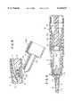
- FIG. 1is a generally perspective view of one form of the fluid delivery device of the present invention.
- FIG. 1Ais an enlarged, cross-sectional view taken along lines 1A--1A of FIG. 1 showing the reservoir fill adapter of the invention connected to the base of the device and the delivery cannula surrounded by one form of the crushable needle cover of the invention.
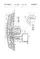
- FIG. 8is a cross-sectional view similar to FIG. 7, but showing the device interconnected with the patient with the needle cover in a crushed configuration.
- FIG. 10is an enlarged, generally perspective view of the collapsible needle cover of the apparatus shown in FIG. 9.
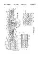
- FIG. 12is a side-elevational, cross-sectional view similar to FIG. 11 but showing the device interconnected with the patient with the bellows which surrounds the cannula in a collapsed configuration.
- FIG. 13is a side-elevational, cross-sectional view of still another alternate form of the invention having a different type of needle cover from that shown in FIGS. 1A and 9.
- FIG. 14is an enlarged, generally perspective view of the collapsible needle cover of the apparatus shown in FIG. 13.
- FIG. 18is a side-elevational, cross-sectional similar to FIG. 17, but showing a different type of reservoir fill means interconnected with the outwardly extending fill adapter of the device shown in FIG. 17.
- FIG. 19is a cross-sectional view of the pusher sleeve assembly of the reservoir fill means shown in FIG. 18.
- FIG. 21is an enlarged, cross-sectional view taken along lines 21--21 of FIG. 17.
- FIG. 22is an enlarged, cross-sectional view of the area designated as 22 in FIG. 18.
- FIG. 23is an enlarged view taken along lines 23--23 of FIG. 19.
- FIG. 24is a cross-sectional view taken along lines 24--24 of FIG. 19.
- FIG. 30is a cross-sectional view taken along lines 30--30 of FIG. 27.
- FIG. 31is a fragmentary top plan view of the infusion means of this latest form of the invention.
- FIG. 32is a fragmentary top plan view of a portion of the flow control element of the infusion means shown in FIG. 31.
- FIG. 33is a cross-sectional view taken along lines 33--33 of FIG. 31 showing the infusion means connected to the patient.
- FIG. 34is a generally perspective view of the infusion cannula of the apparatus shown in FIG. 31.
- FIG. 34Ais a fragmentary, generally perspective view of an alternate form of cannula and flow control means wherein the flow control means is disposed within a collar formed on the cannula.
- FIG. 35is an enlarged, generally perspective view of the collapsible needle cover of the infusion means of this latest form of the invention.
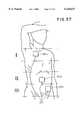
- FIG. 37is a generally illustrative view showing the various locations at which the infusion means can be affixed to the patient.
- Membrane 34can be constructed from a single membrane or from multiple membranes which are overlayed to form a laminate construction or alternatively form a coated single membrane.
- ullage defining meansfor providing ullage within the reservoir and for engagement with membrane 34 as the membrane moves toward its less distended starting configuration.
- the ullage defining meanshere comprises the previously identified, dome shaped central portion 24a of base 22.
- distendable membrane 34examples include: silicone polymers (polysiloxanes) (high performance silicone elastomers made from high molecular weight polymers with appropriate fillers added). These materials are castable into thin film membranes and have high permeability (which allows maximum transport of vapor and gas), high bond and tear strength and excellent low temperature flexibility and radiation resistance. Additionally, silicone elastomers retain their properties over a wide range of temperatures (-80° to 200° C.) are stable at high temperatures, and exhibit tensile strengths up to 2,000 lb./in 2 elongation up to 600%. Another suitable material for the stored energy membrane is natural and synthetic latex.
- these componentscan also be produced from a variety of materials including one of several polymer groups.
- the degree of hardness of these materialscan range from soft, resilient or rigid, and the following polymers can be employed: Polypropylene (PP), Ultra high molecular weight polyethylene (UHMW PE), High density polyethylene (HDPE), Polyvinylidene Fluoride (PVDF), Ethylenevinyl acetate (EVA), Styrene Acrylonitrile (SAN), Polytetrafluoroethylene (PTFF).
- PPPolypropylene
- UHMW PEUltra high molecular weight polyethylene
- HDPEHigh density polyethylene
- PVDFPolyvinylidene Fluoride
- EVAEthylenevinyl acetate
- SANStyrene Acrylonitrile
- PTFFPolytetrafluoroethylene
- a suitable source of these materialsis Porex Technologies of Fairburn, Ga. It is to be understood that other suitable materials well known to those skilled in the art can also be used, including
- This materialis a clear rubber modified Acrylonitrile Copolymer which has wide application in the packaging industry because of its superior gas barrier, chemical resistance and extrusion (thermoforming) and injection molding capabilities.
- the infusion means of this latest form of the invention for subdermal infusion of medicaments into the patientcan be seen to include, a downwardly extending hollow cannula 44 which is carried by a support member 46 that is received within a cavity 48 formed in base 22.
- Support member 46also functions to support, within a cavity 47, flow control means for controlling the rate of fluid flow from reservoir 30 toward hollow cannula 44.
- This flow control meansis here provided as a porous rate control frit 49 which can be constructed from a micro porous metal such as stainless steel.
- the fritcan also be constructed from a porous ceramic or porous plastic material.
- the rate control meanscan take the form of an assembly of the character shown in FIG. 27A which comprises a filter element and a novel wafer-like element having a laser drilled microbore. The details of this alternate type of flow control means will be described in greater detail hereinafter.
- the filling meansfunctions to controllably fill reservoir 30 with the medicinal fluid which is to be infused into the patient.
- the filling meanscomprises a septum 60, a filling syringe assembly and a novel fill adapter assembly.
- septum 60which comprises a pierceable elastomer, is sealably disposed within the previously mentioned fill port assembly 32 which is connected to base 22.
- fill port assembly 32includes a base portion 32a which engages the fill adapter 64 of the invention when the fill adapter is connected to base 22 in the manner shown in FIGS. 1A, 3 and 4.
- fill adapter 64includes a flange 65, which engages the fill port assembly 32.
- Adapter 64also includes a lower, generally cylindrical wall portion 64b and a generally cylindrical intermediate wall portion 64c. As best seen in FIG. 3, the upper extremity of wall portion 64c is necked down to define a small cannula receiving opening 64d and flange 65 of the adapter is receivable within a cavity 67 formed in base 22 so that the adapter can be joined to the base.
- a filling syringe assembly 68which, as best seen in FIG. 6, includes a vial like container 70 having a fluid reservoir 70a, a needle housing 72 closing fluid reservoir 70a, and a double ended piercing needle 76 carried by needle housing 72.
- Filling syringe assembly 68also includes an elongated housing assembly 78 which houses medicament vial 70.
- Housing assembly 78is made up of a hollow housing 78a and a spacer sleeve 78b which insures a close fit of vial 70 within hollow housing 78a. As shown in FIGS.
- a protective cover 83is first pulled away from the bottom of adapter 64 (FIG. 1A) and protective cap 85 is removed from the syringe assembly (FIG. 6).
- needle housing 72 along with needle 76are telescopically inserted into adapter 64 in the manner shown in FIG. 4 so that the boss 73 of needle housing 72 is closely received within the lower part of intermediate portion 64c.
- cylindrical body section 64c of adapter 64is provided with a serration 64e which permits body section 64c to be easily separated from flange 65 by a twisting motion in the manner shown in FIG. 5.
- the upper necked down area of wall portion 64cwill deform in a manner to substantially close cannula receiving opening 64d so that the reservoir of the device cannot be refilled.
- a suitable polymeris preferably used to form the adapter. Examples of suitable materials for this purpose include silicon, vinyl and polypropylene. It is to be understood that, although the fill adapter is shown interconnected with the lower surface of the base of the device, it could also be connected to the side surfaces or to any other convenient surface.
- portions 64b and 64c of the fill adapterare separated from flange 65 by twisting the adapter in the manner described in the preceding paragraph which results in the substantial closing of cannula receiving aperture 64d (FIG. 5).
- cover assembly 52is removed from cavity 55 and peel away member 28b is removed so that the device is in condition for interconnection with the patient. This is accomplished by pressing the base 50a of crushable cover 50 against the patient's skin "S" (see FIG. 7). A downward force exerted against cover 36 will cause crushable cover 50 to crush in the manner shown in FIG.
- the highly novel crushable cover 50can be constructed from various materials including a low-density, open cell foam such as a hydrophilic polyurethane product sold by Hampshire Chemical Corporation of Lexington, Mass. under the name and style HYPOL.
- Cover 50is non-resilient so that, after being crushed, it will remain in the configuration shown in FIG. 8 and thereby will not interfere with the positioning of the base against the patient's skin.
- Cover 50could also be constructed from a low density hydrophobic foam, such as polyisoprene, from a soft polymer gel or a hydrophobic gel that is swollen with mineral oil and from like materials.
- Cover 50preferably includes an adhesive coated upper surface 50c which functions to affix the cover to a potting material 51 which surrounds the neck 46a of support member 46. To protect surface 50c prior to assembly, a peel away cover 50b is provided (see FIG. 2).
- FIGS. 9 through 12an alternate form of the invention is there shown.
- This alternate embodimentis similar in many respects to that shown in FIGS. 1 through 8 and like numerals are used to identify like components.
- the major difference between this latest embodiment and that shown in FIGS. 1 through 8,concerns the infusion means for subdermal infusion of medicaments into the patient.
- this infusion meansincludes a downwardly extending hollow cannula 44 which is carried by a support member 46 that is received within a cavity 55 formed in base 22.
- support member 46functions to support flow control means of the character previously described for controlling the rate of fluid flow from reservoir 30 toward hollow cannula 44.
- the coveris here provided as a uniquely configured, yieldably deformable collapsible bellows assembly 102.
- Bellows assembly 102surrounds cannula 44 in the manner shown in FIG. 9 and is movable from the extended position shown in FIG. 9 to the collapsed position shown in FIG. 12.
- bellows assembly 102includes a bellows-like body 104 having an adhesive coated upper surface 104a (FIG. 10) and a collapsible sidewall 104b. Prior to interconnecting the bellows 104 to base 22, surface 104a is protected by a peel-away cover 106.
- portions 64b and 64c of the fill adapterare broken away from the flange 65 along serrations 64e (see FIG. 5).
- cover assembly 52is removed from cavity 55 and peel away member 28b is stripped away so that the device is placed in condition for interconnection with the patient.
- Thisis accomplished by pressing the base 104c of bellows body 104 against the patient's skin "S" (see FIG. 11).
- a downward force exerted against cover 36will cause bellows body 104 to collapse in the manner shown in FIG. 12 allowing the needle portion 44d of the cannula to first penetrate and pass through base 104c and then to enter the patient's skin and tissue in the manner shown in FIG. 12.
- adhesive pad 28will grip the patient's skin so as to hold the device securely in position with the cannula appropriately implanted in a subdermal or introdermal position.
- Balloon-like member 112surrounds cannula 44 in the manner shown in FIG. 13 and is yieldably deformable from the position shown in FIG. 13 to the collapsed position shown in FIG. 16.
- member 112includes a body 114 having an adhesive coated upper surface 114a (FIG. 13) and a yieldably deformable sidewall 114b. Prior to interconnecting member 112 to base 22, surface 114a is protected by a peel-away cover 116.
- Member 112can be constructed from various yieldably deformable materials, including the materials used to construct the collapsible bellows 104.
- FIGS. 17 through 26yet another form of the fluid delivery apparatus of the invention is there shown and generally designated by the numeral 120 (FIG. 18).
- This form of the inventionwhich is also designed for subdermal infusion of selected medicaments, comprises a base 122 having an upper surface 124, including a generally dome shaped central portion 124a and a peripheral portion 124b circumscribing central portion 124a.
- base 122is provided with a lower surface 126 to which a patient interconnection means or adhesive pad assembly 128 is connected.
- Pad assembly 128,which is of similar construction to pad assembly 28, functions to releasably interconnect the device to the patient so as to hold it securely in place during the medicament delivery step.
- ullage defining meansfor providing ullage within the reservoir and for engagement with membrane 134 as the membrane moves toward its less distended starting configuration.
- the ullage defining meanshere comprises the previously identified, dome shaped central portion 124a of base 122.
- cover meansSuperimposed over base 122 is the cover means, shown here as a vented rigid cover 136 which functions, through the use of novel capture means, to retain and sealably enclose membrane 134.
- the sealing meansis of the character described in connection with the embodiment shown in FIGS. 1 through 8 and operates in precisely the same way to sealably clamp distendable membrane 134 between the cover and the base.
- the same materials previously discussed for constructing the cover, the base and the distendable membranecan be used to construct the components of this latest form of the invention.
- hollow cannula 144has an inlet end 144a and an outlet end 144b formed in a needle-like segment 144c which extends generally perpendicularly downward from the lower surface 126 of base 122 (FIG. 26) and terminates in a piercing point 144d.
- a protective cover assembly 152surrounds cannula 144 in the manner shown in FIGS. 17 and 22.
- Cover assembly 152includes a downwardly depending generally cylindrically shaped portion 152a and an upper end 152b which is closely receivable over a boss 146a formed on support 146.
- cover assembly 152can be removed from boss 146a to expose cannula 144 by gripping finger gripping means here provided as a tab 152c formed on a cover 152 which closes the outboard end of cylindrical portion 152a.
- gripping finger gripping meanshere provided as a tab 152c formed on a cover 152 which closes the outboard end of cylindrical portion 152a.
- the novel filling means of this latest form of the inventionis there illustrated.
- the filling meansfunctions to controllably fill reservoir 130 with the medicinal fluid which is to be infused into the patient.
- the filling meanscomprises a septum 160 which is mounted within a cavity 161 formed in peripheral portion 124b of base 122; a vial type fill assembly 163 (FIG. 18) and a novel fill adapter assembly 164.
- the fill adapter assembly 164is integrally formed with and extends outwardly from the side of base 122 in the manner shown in FIGS. 17 and 18.
- fill adapter 164includes a generally cylindrical, reduced diameter neck portion 164a, which cooperates with base 122 to define the fill port 132 of the device and an enlarged diameter, hollow body portion 164b connected to reduced diameter portion 164a (FIG. 17).
- portion 164aForming a part of portion 164a is a central, twist-off segment 165 which is provided with a serration 165a, the purpose of which will presently be described.
- Adapter assembly 164also includes a pair of twist-off wings 164c, for use in separating adapter assembly 164 from base 122.
- Slidably disposed within neck portion 164ais a needle holder 166a which supports a double ended piercing cannula 166.
- filling assembly 163which comprises the previously mentioned vial type fill assembly 163.
- fill assembly 163includes a vial-like container 170 having a container reservoir 170a and a pierceable septum 172 closing one end of fluid reservoir 170a. Closing the opposite end of reservoir 170a is a telescopically movable plunger 174. Plunger 174 is telescopically movable longitudinally of reservoir 170a by a pusher sleeve assembly 176 which also forms a part of the filling means. Referring to FIG.
- pusher sleeve assembly 176comprises a hollow housing 176a which is open at one end to telescopically receive vial 170 and is closed at its opposite end by a closure wall 177. Integrally formed with wall 177 and extending inwardly of housing 176a is a pusher member 179, the inboard end of which engages plunger 174 to move the plunger along the length of reservoir 170a as housing 176 is telescopically mated with body portion 164b of adapter assembly 164 (see also FIG. 24).
- cover assembly 152is removed from the delivery component to expose piercing cannula 144 so as to place the apparatus in condition for interconnection with the patient. This step is accomplished by pressing the base 153a of telescoping cover 153 against the patient's skin. Next, a downward force exerted against cover 136 of the delivery component will cause segments 155a, 155b, and 155c (FIG. 22) of cover 153 to telescope relative to one another in the manner illustrated in FIG. 26 allowing the needle portion 144d of the cannula to freely penetrate the patient's skin and tissue.
- the novel telescoping cover 153can be constructed from various types of resilient plastic materials such as thermoplastic materials with low sliding friction that will permit the walls of the system to deform sufficiently to permit the telescoping segments to be telescoped in the manner shown in FIG. 26 upon a downward force being exerted on cover 136.
- suitable materials for constructing cover assembly 153include polyethylene, polypropylene and polycarbonate.
- FIGS. 27 through 37still another form of the fluid delivery device of the invention is there shown and generally designated by the numeral 200.
- This deviceis similar in many respects to that shown in FIGS. 1 through 26 and like numerals are used in FIGS. 27 through 37 to identify like components.
- the primary difference between the earlier described embodiment and the embodiment of FIGS. 27 through 37resides in the differently configured fluid flow control means and the totally different infusion means of the invention for infusing medicinal fluids into the patient. The details of construction of both of these novel features of the invention will presently be described.
- a stored energy meanscooperates with the upper surface 204 of base 202 to form a reservoir 210 having an inlet port 212, which is adapted to cooperate with a filling means of this latest form of the invention for filling reservoir 210 with the medicinal fluid to be infused into the patient.
- the stored energy meansis here provided in the form of a laminate construction or assemblage 214 which is made up of first and second distendable membranes 214a and 214b (FIG. 29) which are here shown as coated, for specialized biocompatibility purposes, with a flurosilicone barrier material 214c.
- Membrane assemblage 214is distendable as a result of pressure imparted on the membrane by fluids "F" introduced into reservoir 210 through inlet portion 212. As the membrane assemblage is distended in the manner shown in FIGS. 27 and 29, internal stresses will be established, which stresses tend to move the assemblage toward a less distended configuration and in a direction toward base 202.
- ullage defining meansfor providing ullage within the reservoir and for engagement with membrane 214 as the membrane moves toward its less distended starting configuration.
- the ullage defining meanshere comprises the dome shaped central portion 204a of base 202.
- cover meansSuperimposed over base 202 is the cover means, shown here as a rigid cover 216, which is of the same general character as previously described, and through the use of novel sealing means, functions to sealably enclose membrane 214.
- the sealing meansis identical to that previously described in connection with the embodiment shown in FIGS. 1 through 6.
- the filling means of this latest form of the inventionis quite similar in construction and operation to that shown in FIG. 1 and comprises a septum assembly 66 which is sealably disposed within fill port 212 formed in the intermediate portion of base 202 (see FIG. 12).
- Septum assembly 66includes an elastomeric pierceable core 66b which is sealably disposed within a core housing 66a.
- septum assembly 66is disposed proximate the upper end of a fill adapter which is similar to that previously described in connection with FIGS. 1 through 6. However, as best seen in FIG.
- the filing syringe component of the filling means of this latest form of the inventionis identical to that previously described and the upper part of the filling syringe is receivable within the lower portion 215c of fill adapter 215 in the same manner as depicted in FIG. 4.
- this novel infusion meanshere comprises an administration set 219 having a subcutaneous infusion device 220 (FIG. 31) and connector means for operably interconnecting device 220 with the fluid reservoir 210 of the fluid delivery device.
- the connector meanshere comprises a connector boss 222 and a length of tubing 224 which interconnects device 220 with boss 222 (FIG. 31).
- Connector boss 222is sealably received within a connector boss receiving port 226 formed in base 202 and cover 216 (FIG.
- Wafer 27acomprises a porous base 244, a wafer-like element or wafer 246 and a filter 248.
- Wafer 246,which can be constructed from various metals and plastics, has a centrally disposed, laser drilled microbore 246a (for example, one micron to 50 microns in diameter), which precisely controls fluid flow from reservoir 210 toward the administration set 219.
- Wafer-like element 246which is a very thin film material (for example 0.010 to 0.030 inches) can be constructed from various materials including a polyamide material sold by duPont under the name and style KAPTON.
- element 246cooperates with a second flow control means provided in the form of a porous frit-like element 247 (FIG. 34) to precisely control fluid flow from the apparatus of the invention.
- Infusion device 220 of the administration sethere comprises a base 245 having upper and lower surfaces 245a and 245b and a generally circular shaped opening 249. Connected to base 245 is a cover 251. Cover 251 and base 245 cooperate to define an internal chamber 250 within which a generally spiral shaped cannula 252 is dynamically mounted.
- Cannula 252includes a circuitously shaped body portion 252a which is disposed within chamber 250 and a stem portion 252b which is mounted between base 245 and cover 251 in a manner presently to be described.
- the second fluid flow control means of the inventionDisposed within stem portion 252b is the previously mentioned second fluid flow control means of the invention, which here comprises an elongated, generally cylindrically shaped flow control element 247.
- Element 247cooperates with the first flow control means or assemblage 240 to precisely regulate fluid flow from the device.
- Element 247can be constructed from various materials including porous ceramic, plastic and metal.
- Cannula 252also includes an outlet end, here provided in the form of a needle-like segment 252c, which extends generally perpendicularly downward from lower surface 245b of base 245 for subdermal infusion of medicinal fluids into the patient.
- segment 252cis provided with a sharp, pointed extremity 252d (see FIG. 34).
- cannula 252is provided with an enlarged diameter collar 252f which houses porous flow control frit 247.
- Frit 247can be secured within collar 252f by various joining methods including adhesive weldment.
- Collar 252fis preferably secured to the cannula body by plasma weldment.
- infusion device 220can be interconnected with the patient for subdermal delivery of fluids from the fluid delivery portion of the apparatus. This is accomplished by breaking away adapter 215 so as to present a smooth lower surface on the fluid storage component so that it can be connected to the patient and by removing protective sheath 257 so that the subcutaneous infusion component can be connected to the patient at a location remote from the fluid storage component.
- FIG. 37there is shown, by way of example, three possible locations for affixing the storage component of the invention and three possible locations for affixing the subcutaneous infusion component to the patient.
- the choice of location of the larger, more bulky storage componentmay be simply a matter of convenience.
- the infusion componentis lighter and occupies a much smaller surface area on the patient, the patient can select optimum infusion sites at locations on the torso where affixation of the storage component is impractical.
- the storage component 201ais located on the chest of the patient, while storage component 201b is located on the stomach and storage component 201c is located just below the belt line.
- the subcutaneous infusion component 220can be comfortably and conveniently positioned just above the pelvic area where there generally is an area of pronounced subdermal fat.
- Interconnection of the subcutaneous infusion component of the apparatusis accomplished by pressing the now exposed base 253c of crushable cover body 253a against the patient's skin "S" (see FIG. 33).
- a downward force exerted against cover 251will cause crushable body 253a to collapse into chamber 250 in the manner shown in FIG. 33 allowing the needle portion 252d of the cannula to penetrate the patient's skin and tissue in the manner shown in FIG. 33.
- This unique construction of the needle coverenables the patient to use the device without being aware of the insertion of the needle into the skin while at the same time maintaining the needle in a substantially aseptic condition.
- the highly novel crushable cover body 253acan be constructed from various materials including a low density open cell foam such as a hydrophilic polyurethane product sold by Hampshire Chemical Corporation of Lexington, Mass. under the name and style HYPOL. Body 253a could also be constructed from a low density hydrophobic foam, such as polyisoprene, from a soft polymer gel or a hydrophobic gel that is swollen with mineral oil and from pl 69 like materials.
- a low density open cell foamsuch as a hydrophilic polyurethane product sold by Hampshire Chemical Corporation of Lexington, Mass. under the name and style HYPOL.
- Body 253acould also be constructed from a low density hydrophobic foam, such as polyisoprene, from a soft polymer gel or a hydrophobic gel that is swollen with mineral oil and from pl 69 like materials.
- an extremely important aspect of the infusion device 220resides in the novel design of the circuitous cannula 252 and its unique interconnection with the base 245 and cover 251 of the infusion device.
- the devicewhen the device is connected to the patient, in the manner shown in FIG. 33, with the needle portion 252c of the cannula penetrating the patient's body as, for example, the patent's abdomen (see also FIG. 37), increased patient comfort is provided since normal movement by the patient will permit the cannula to move within chamber 250 while the base remains completely stationary. Without this important feature, normal movements by the patient causing flexing of the muscle and tissue could cause needle necrosis, irritation and discomfort to the patient with prolonged use.
Landscapes
- Health & Medical Sciences (AREA)
- Vascular Medicine (AREA)
- Engineering & Computer Science (AREA)
- Anesthesiology (AREA)
- Biomedical Technology (AREA)
- Heart & Thoracic Surgery (AREA)
- Hematology (AREA)
- Life Sciences & Earth Sciences (AREA)
- Animal Behavior & Ethology (AREA)
- General Health & Medical Sciences (AREA)
- Public Health (AREA)
- Veterinary Medicine (AREA)
- Infusion, Injection, And Reservoir Apparatuses (AREA)
Abstract
Description
Claims (18)
Priority Applications (4)
| Application Number | Priority Date | Filing Date | Title |
|---|---|---|---|
| US09/061,087US6126637A (en) | 1998-04-15 | 1998-04-15 | Fluid delivery device with collapsible needle cover |
| EP99917468AEP1071406A4 (en) | 1998-04-15 | 1999-04-14 | Fluid delivery device with collapsible needle cover |
| PCT/US1999/008092WO1999052509A1 (en) | 1998-04-15 | 1999-04-14 | Fluid delivery device with collapsible needle cover |
| AU35585/99AAU3558599A (en) | 1998-04-15 | 1999-04-14 | Fluid delivery device with collapsible needle cover |
Applications Claiming Priority (1)
| Application Number | Priority Date | Filing Date | Title |
|---|---|---|---|
| US09/061,087US6126637A (en) | 1998-04-15 | 1998-04-15 | Fluid delivery device with collapsible needle cover |
Publications (1)
| Publication Number | Publication Date |
|---|---|
| US6126637Atrue US6126637A (en) | 2000-10-03 |
Family
ID=22033516
Family Applications (1)
| Application Number | Title | Priority Date | Filing Date |
|---|---|---|---|
| US09/061,087Expired - Fee RelatedUS6126637A (en) | 1998-04-15 | 1998-04-15 | Fluid delivery device with collapsible needle cover |
Country Status (4)
| Country | Link |
|---|---|
| US (1) | US6126637A (en) |
| EP (1) | EP1071406A4 (en) |
| AU (1) | AU3558599A (en) |
| WO (1) | WO1999052509A1 (en) |
Cited By (149)
| Publication number | Priority date | Publication date | Assignee | Title |
|---|---|---|---|---|
| US6440096B1 (en)* | 2000-07-14 | 2002-08-27 | Becton, Dickinson And Co. | Microdevice and method of manufacturing a microdevice |
| WO2002068013A3 (en)* | 2000-12-18 | 2002-10-24 | Science Inc | Multiple canopy |
| US20040015131A1 (en)* | 2002-07-16 | 2004-01-22 | Flaherty J. Christopher | Flow restriction system and method for patient infusion device |
| US20040092875A1 (en)* | 2002-11-08 | 2004-05-13 | Kochamba Gary Steven | Cutaneous injection delivery under suction |
| EP1502613A1 (en)* | 2003-08-01 | 2005-02-02 | Novo Nordisk A/S | Needle device with retraction means |
| US20050033233A1 (en)* | 2003-08-04 | 2005-02-10 | Kriesel Marshall S. | Infusion apparatus with constant force spring energy source |
| US20050033232A1 (en)* | 2003-08-05 | 2005-02-10 | Kriesel Marshall S. | Infusion apparatus with modulated flow control |
| US20050038387A1 (en)* | 2003-08-04 | 2005-02-17 | Kriesel Marshall S. | Multichannel fluid delivery device |
| WO2005068001A1 (en)* | 2004-01-16 | 2005-07-28 | Disetronic Licensing Ag | Injection needle assembly comprising an injection needle and a needle guide |
| US20050263615A1 (en)* | 2004-05-26 | 2005-12-01 | Kriesel Marshall S | Fluid delivery apparatus with adjustable flow rate control |
| US20050277883A1 (en)* | 2004-05-26 | 2005-12-15 | Kriesel Marshall S | Fluid delivery device |
| US20050277884A1 (en)* | 2004-05-26 | 2005-12-15 | Kriesel Marshall S | Fluid delivery apparatus with bellows reservoir |
| US20050277882A1 (en)* | 2004-05-26 | 2005-12-15 | Kriesel Marshall S | Infusion apparatus |
| US20060095014A1 (en)* | 2003-05-08 | 2006-05-04 | Novo Nordisk A/S | External inserter for transcutaneous device |
| US20060195057A1 (en)* | 2005-02-18 | 2006-08-31 | Kriesel Marshall S | Fluid delivery apparatus with vial fill |
| US20060196552A1 (en)* | 2005-02-17 | 2006-09-07 | Kriesel Marshall S | Distal rate control device |
| US20060206052A1 (en)* | 2005-02-15 | 2006-09-14 | Kriesel Marshall S | Fluid delivery and mixing apparatus with flow rate control |
| US7118552B2 (en) | 2000-02-18 | 2006-10-10 | Astrazeneca Ab | Automatically operable safety shield system for syringes |
| US20060264926A1 (en)* | 2002-11-08 | 2006-11-23 | Kochamba Gary S | Cutaneous stabilization by vacuum for delivery of micro-needle array |
| US20060282290A1 (en)* | 2002-09-30 | 2006-12-14 | Insulet Corporation | Components and Methods For Patient Infusion Device |
| US20070016149A1 (en)* | 2004-01-16 | 2007-01-18 | Marcel Hunn | Injection Needle |
| US20070156090A1 (en)* | 2004-05-26 | 2007-07-05 | Kriesel Marshall S | Fluid delivery apparatus |
| US20070219501A1 (en)* | 2006-03-15 | 2007-09-20 | Kriesel Marshall S | Fluid dispensing apparatus |
| US20070299408A1 (en)* | 2006-03-16 | 2007-12-27 | Seattle Medical Technologies | Infusion device pump |
| US20080009835A1 (en)* | 2005-02-17 | 2008-01-10 | Kriesel Marshall S | Fluid dispensing apparatus with flow rate control |
| US20080243077A1 (en)* | 2007-04-02 | 2008-10-02 | Bivin Donald B | Fluid dispenser with uniformly collapsible reservoir |
| US20080281276A1 (en)* | 2007-05-10 | 2008-11-13 | Nilimedix Ltd. | Infusion set self-occlusion mechanism |
| US20080287871A1 (en)* | 2002-04-02 | 2008-11-20 | Wilkinson Bradley M | Method and Device for Intradermally Delivering a Substance |
| US20080319385A1 (en)* | 2007-06-25 | 2008-12-25 | Kriesel Marshall S | Fluid dispenser with additive sub-system |
| US20090024083A1 (en)* | 2007-06-25 | 2009-01-22 | Kriesel Marshall S | Fluid dispenser with additive sub-system |
| US20090048563A1 (en)* | 2004-12-06 | 2009-02-19 | Novo Nordisk A/S | Ventilated Skin Mountable Device |
| US20100069848A1 (en)* | 2008-09-12 | 2010-03-18 | Calibra Medical, Inc. | Wearable infusion assembly |
| US20100160861A1 (en)* | 2000-03-23 | 2010-06-24 | Medtronic Minimed, Inc. | Control Tabs for Infusion Devices and Methods of Using the Same |
| US7780636B2 (en) | 2003-07-08 | 2010-08-24 | Novo Nordisk A/S | Portable drug delivery device having an encapsulated needle |
| US7828772B2 (en) | 2006-03-15 | 2010-11-09 | Bioquiddity, Inc. | Fluid dispensing device |
| US20110004187A1 (en)* | 2009-07-01 | 2011-01-06 | Michael James Beiriger | Drug Delivery Methods And Related Products |
| US7922462B2 (en) | 2004-03-30 | 2011-04-12 | Novo Nordisk A/S | Actuator system comprising lever mechanism |
| US20110160696A1 (en)* | 2009-12-31 | 2011-06-30 | Abbott Diabetes Care Inc. | Injection port device adapted for use with insulin pump |
| US7981085B2 (en) | 2003-05-08 | 2011-07-19 | Novo Nordisk A/S | Internal needle inserter |
| US7985216B2 (en) | 2004-03-16 | 2011-07-26 | Dali Medical Devices Ltd. | Medicinal container engagement and automatic needle device |
| US8057435B2 (en) | 2006-07-31 | 2011-11-15 | Kriesel Joshua W | Fluid dispenser |
| US8167841B2 (en) | 2005-01-24 | 2012-05-01 | Novo Nordisk A/S | Transcutaneous device assembly |
| US8292848B2 (en) | 2006-07-31 | 2012-10-23 | Bio Quiddity, Inc. | Fluid dispensing device with additive |
| US8376998B2 (en) | 2003-09-17 | 2013-02-19 | Elcam Medical Agricultural Cooperative Association Ltd. | Automatic injection device |
| WO2013086463A1 (en)* | 2011-12-07 | 2013-06-13 | Becton, Dickinson And Company | Infusion device with releasable fluid connector |
| US8557179B2 (en) | 2007-10-31 | 2013-10-15 | Novo Nordisk A/S | Non-porous material as sterilization barrier |
| US8740851B2 (en) | 2003-05-08 | 2014-06-03 | Novo Nordisk A/S | Integrated package |
| US8945071B2 (en) | 2010-09-02 | 2015-02-03 | Becton, Dickinson And Company | Self-injection device having needle cover with activation preventer |
| US8961469B2 (en) | 2009-12-16 | 2015-02-24 | Becton, Dickinson And Company | Self-injection device |
| US9022972B2 (en) | 2009-08-18 | 2015-05-05 | Cequr Sa | Medicine delivery device having detachable pressure sensing unit |
| US9061097B2 (en) | 2010-06-07 | 2015-06-23 | Amgen Inc. | Drug delivery device |
| US20150216942A1 (en)* | 2014-01-31 | 2015-08-06 | Midatech Limited | Nanoparticle-insulin and insulin analogue compositions |
| US9144646B2 (en) | 2012-04-25 | 2015-09-29 | Fresenius Medical Care Holdings, Inc. | Vial spiking devices and related assemblies and methods |
| US9173992B2 (en) | 2006-03-13 | 2015-11-03 | Novo Nordisk A/S | Secure pairing of electronic devices using dual means of communication |
| US9174009B2 (en) | 2009-08-18 | 2015-11-03 | Cequr Sa | Methods for detecting failure states in a medicine delivery device |
| US9399094B2 (en) | 2006-06-06 | 2016-07-26 | Novo Nordisk A/S | Assembly comprising skin-mountable device and packaging therefore |
| US9555187B2 (en) | 2009-12-16 | 2017-01-31 | Becton, Dickinson And Company | Self-injection device |
| US9579461B2 (en) | 2009-12-16 | 2017-02-28 | Becton, Dickinson And Company | Self-injection device |
| US9662436B2 (en) | 2013-09-20 | 2017-05-30 | Icu Medical, Inc. | Fail-safe drug infusion therapy system |
| US9717850B2 (en) | 2009-12-16 | 2017-08-01 | Becton, Dickinson And Company | Self-injection device |
| US20170258713A1 (en)* | 2005-06-24 | 2017-09-14 | 3M Innovative Properties Company | Collapsible patch andmethod of application |
| US9833562B2 (en) | 2009-12-16 | 2017-12-05 | Becton, Dickinson And Company | Self-injection device |
| US9971871B2 (en) | 2011-10-21 | 2018-05-15 | Icu Medical, Inc. | Medical device update system |
| US9987406B2 (en) | 2011-02-08 | 2018-06-05 | Fresenius Medical Care Holdings, Inc. | Magnetic sensors and related systems and methods |
| US10042986B2 (en) | 2013-11-19 | 2018-08-07 | Icu Medical, Inc. | Infusion pump automation system and method |
| US10064987B2 (en) | 2011-01-31 | 2018-09-04 | Fresenius Medical Care Holdings, Inc. | Preventing over-delivery of drug |
| CN108697852A (en)* | 2016-02-29 | 2018-10-23 | 欧弗洛有限公司 | Cover body and liquid medicine injection device having the same |
| US10195340B2 (en) | 2009-12-16 | 2019-02-05 | Becton, Dickinson And Company | Self-injection device |
| US10238801B2 (en) | 2009-04-17 | 2019-03-26 | Icu Medical, Inc. | System and method for configuring a rule set for medical event management and responses |
| US10242060B2 (en) | 2006-10-16 | 2019-03-26 | Icu Medical, Inc. | System and method for comparing and utilizing activity information and configuration information from multiple medical device management systems |
| US10238799B2 (en) | 2014-09-15 | 2019-03-26 | Icu Medical, Inc. | Matching delayed infusion auto-programs with manually entered infusion programs |
| WO2019075337A1 (en)* | 2017-10-12 | 2019-04-18 | Enable Injections, Inc. | Injection device with adhesive assembly |
| US10311972B2 (en) | 2013-11-11 | 2019-06-04 | Icu Medical, Inc. | Medical device system performance index |
| US10314974B2 (en) | 2014-06-16 | 2019-06-11 | Icu Medical, Inc. | System for monitoring and delivering medication to a patient and method of using the same to minimize the risks associated with automated therapy |
| US10333843B2 (en) | 2013-03-06 | 2019-06-25 | Icu Medical, Inc. | Medical device communication method |
| US10350349B2 (en) | 2014-05-20 | 2019-07-16 | Cequr Sa | Medicine delivery device with restricted access filling port |
| US10363342B2 (en) | 2016-02-04 | 2019-07-30 | Insulet Corporation | Anti-inflammatory cannula |
| US10434246B2 (en) | 2003-10-07 | 2019-10-08 | Icu Medical, Inc. | Medication management system |
| WO2019213598A1 (en)* | 2018-05-03 | 2019-11-07 | Hemotek Medical Incorporated | Needle safety systems |
| US10692595B2 (en) | 2018-07-26 | 2020-06-23 | Icu Medical, Inc. | Drug library dynamic version management |
| US10729846B2 (en)* | 2010-09-10 | 2020-08-04 | C. R. Bard, Inc. | Self-sealing pad for a needle-based infusion set |
| US10741280B2 (en) | 2018-07-17 | 2020-08-11 | Icu Medical, Inc. | Tagging pump messages with identifiers that facilitate restructuring |
| US10737030B2 (en) | 2012-11-09 | 2020-08-11 | Iinjec Technologies Inc. | Fluid delivery device and method |
| US10777319B2 (en) | 2014-01-30 | 2020-09-15 | Insulet Netherlands B.V. | Therapeutic product delivery system and method of pairing |
| US10806900B2 (en) | 2010-09-10 | 2020-10-20 | C. R. Bard. Inc. | Insertion device with interface pad and methods of making |
| US10861592B2 (en) | 2018-07-17 | 2020-12-08 | Icu Medical, Inc. | Reducing infusion pump network congestion by staggering updates |
| US10898641B2 (en) | 2014-04-30 | 2021-01-26 | Icu Medical, Inc. | Patient care system with conditional alarm forwarding |
| US10898656B2 (en) | 2017-09-26 | 2021-01-26 | Insulet Corporation | Needle mechanism module for drug delivery device |
| US10994075B2 (en) | 2014-04-11 | 2021-05-04 | Hemotek Medical Incorporated | Systems and methods for automatic termination of flow due to needle dislodgement |
| US11045603B2 (en) | 2017-02-22 | 2021-06-29 | Insulet Corporation | Needle insertion mechanisms for drug containers |
| US11147931B2 (en) | 2017-11-17 | 2021-10-19 | Insulet Corporation | Drug delivery device with air and backflow elimination |
| US20210379293A1 (en)* | 2016-05-26 | 2021-12-09 | Insulet Corporation | Single dose drug delivery device |
| US11235100B2 (en) | 2003-11-13 | 2022-02-01 | Icu Medical, Inc. | System for maintaining drug information and communicating with medication delivery devices |
| US11309070B2 (en) | 2018-07-26 | 2022-04-19 | Icu Medical, Inc. | Drug library manager with customized worksheets |
| US11328805B2 (en) | 2018-07-17 | 2022-05-10 | Icu Medical, Inc. | Reducing infusion pump network congestion by staggering updates |
| US11324889B2 (en) | 2020-02-14 | 2022-05-10 | Insulet Corporation | Compensation for missing readings from a glucose monitor in an automated insulin delivery system |
| US11364341B2 (en) | 2015-11-25 | 2022-06-21 | Insulet Corporation | Wearable medication delivery device |
| US11439754B1 (en) | 2021-12-01 | 2022-09-13 | Insulet Corporation | Optimizing embedded formulations for drug delivery |
| US11446110B2 (en) | 2016-12-21 | 2022-09-20 | Hemotek Medical Incorporated | Needle safety systems |
| US11551802B2 (en) | 2020-02-11 | 2023-01-10 | Insulet Corporation | Early meal detection and calorie intake detection |
| US11547800B2 (en) | 2020-02-12 | 2023-01-10 | Insulet Corporation | User parameter dependent cost function for personalized reduction of hypoglycemia and/or hyperglycemia in a closed loop artificial pancreas system |
| US11565039B2 (en) | 2018-10-11 | 2023-01-31 | Insulet Corporation | Event detection for drug delivery system |
| US11565043B2 (en) | 2018-05-04 | 2023-01-31 | Insulet Corporation | Safety constraints for a control algorithm based drug delivery system |
| US11571508B2 (en) | 2013-08-30 | 2023-02-07 | Icu Medical, Inc. | System and method of monitoring and managing a remote infusion regimen |
| US11574737B2 (en) | 2016-07-14 | 2023-02-07 | Icu Medical, Inc. | Multi-communication path selection and security system for a medical device |
| US11583633B2 (en) | 2018-04-03 | 2023-02-21 | Amgen Inc. | Systems and methods for delayed drug delivery |
| US11587669B2 (en) | 2018-07-17 | 2023-02-21 | Icu Medical, Inc. | Passing authentication token to authorize access to rest calls via web sockets |
| US11596740B2 (en) | 2015-02-18 | 2023-03-07 | Insulet Corporation | Fluid delivery and infusion devices, and methods of use thereof |
| US11605468B2 (en) | 2015-05-26 | 2023-03-14 | Icu Medical, Inc. | Infusion pump system and method with multiple drug library editor source capability |
| US11607493B2 (en) | 2020-04-06 | 2023-03-21 | Insulet Corporation | Initial total daily insulin setting for user onboarding |
| US11628251B2 (en) | 2018-09-28 | 2023-04-18 | Insulet Corporation | Activity mode for artificial pancreas system |
| US11684716B2 (en) | 2020-07-31 | 2023-06-27 | Insulet Corporation | Techniques to reduce risk of occlusions in drug delivery systems |
| US11684713B2 (en) | 2012-03-30 | 2023-06-27 | Insulet Corporation | Fluid delivery device, transcutaneous access tool and insertion mechanism for use therewith |
| US11724027B2 (en) | 2016-09-23 | 2023-08-15 | Insulet Corporation | Fluid delivery device with sensor |
| US11738144B2 (en) | 2021-09-27 | 2023-08-29 | Insulet Corporation | Techniques enabling adaptation of parameters in aid systems by user input |
| US11801344B2 (en) | 2019-09-13 | 2023-10-31 | Insulet Corporation | Blood glucose rate of change modulation of meal and correction insulin bolus quantity |
| US11833329B2 (en) | 2019-12-20 | 2023-12-05 | Insulet Corporation | Techniques for improved automatic drug delivery performance using delivery tendencies from past delivery history and use patterns |
| US20230414139A1 (en)* | 2020-11-24 | 2023-12-28 | Loop Medical Sa | Sample collection device |
| US11857763B2 (en) | 2016-01-14 | 2024-01-02 | Insulet Corporation | Adjusting insulin delivery rates |
| US11865299B2 (en) | 2008-08-20 | 2024-01-09 | Insulet Corporation | Infusion pump systems and methods |
| US11904140B2 (en) | 2021-03-10 | 2024-02-20 | Insulet Corporation | Adaptable asymmetric medicament cost component in a control system for medicament delivery |
| US11929158B2 (en) | 2016-01-13 | 2024-03-12 | Insulet Corporation | User interface for diabetes management system |
| US11935637B2 (en) | 2019-09-27 | 2024-03-19 | Insulet Corporation | Onboarding and total daily insulin adaptivity |
| USD1020794S1 (en) | 2018-04-02 | 2024-04-02 | Bigfoot Biomedical, Inc. | Medication delivery device with icons |
| US11957875B2 (en) | 2019-12-06 | 2024-04-16 | Insulet Corporation | Techniques and devices providing adaptivity and personalization in diabetes treatment |
| USD1024090S1 (en) | 2019-01-09 | 2024-04-23 | Bigfoot Biomedical, Inc. | Display screen or portion thereof with graphical user interface associated with insulin delivery |
| US11969579B2 (en) | 2017-01-13 | 2024-04-30 | Insulet Corporation | Insulin delivery methods, systems and devices |
| US11986630B2 (en) | 2020-02-12 | 2024-05-21 | Insulet Corporation | Dual hormone delivery system for reducing impending hypoglycemia and/or hyperglycemia risk |
| US12036389B2 (en) | 2020-01-06 | 2024-07-16 | Insulet Corporation | Prediction of meal and/or exercise events based on persistent residuals |
| US12042630B2 (en) | 2017-01-13 | 2024-07-23 | Insulet Corporation | System and method for adjusting insulin delivery |
| US12064591B2 (en) | 2013-07-19 | 2024-08-20 | Insulet Corporation | Infusion pump system and method |
| US12076160B2 (en) | 2016-12-12 | 2024-09-03 | Insulet Corporation | Alarms and alerts for medication delivery devices and systems |
| US12097355B2 (en) | 2023-01-06 | 2024-09-24 | Insulet Corporation | Automatically or manually initiated meal bolus delivery with subsequent automatic safety constraint relaxation |
| US12106837B2 (en) | 2016-01-14 | 2024-10-01 | Insulet Corporation | Occlusion resolution in medication delivery devices, systems, and methods |
| US12115351B2 (en) | 2020-09-30 | 2024-10-15 | Insulet Corporation | Secure wireless communications between a glucose monitor and other devices |
| US12121700B2 (en) | 2020-07-22 | 2024-10-22 | Insulet Corporation | Open-loop insulin delivery basal parameters based on insulin delivery records |
| US12121701B2 (en) | 2021-01-29 | 2024-10-22 | Insulet Corporation | Systems and methods for incorporating co-formulations of insulin in an automatic insulin delivery system |
| US12121405B2 (en) | 2019-08-14 | 2024-10-22 | Hemotek Medical Incorporated | Needle safety systems |
| US12130910B2 (en) | 2019-05-08 | 2024-10-29 | Icu Medical, Inc. | Threshold signature based medical device management |
| US12128215B2 (en) | 2020-09-30 | 2024-10-29 | Insulet Corporation | Drug delivery device with integrated optical-based glucose monitor |
| US12303464B2 (en) | 2020-04-03 | 2025-05-20 | Icu Medical, Inc. | Systems, methods, and components for transferring medical fluids |
| WO2025104039A1 (en)* | 2023-11-14 | 2025-05-22 | Becton Dickinson France | Injection device with sterile sealing member |
| US12318577B2 (en) | 2017-01-13 | 2025-06-03 | Insulet Corporation | System and method for adjusting insulin delivery |
| US12343502B2 (en) | 2017-01-13 | 2025-07-01 | Insulet Corporation | System and method for adjusting insulin delivery |
| US12370307B2 (en) | 2020-02-03 | 2025-07-29 | Insulet Corporation | Use of fuzzy logic in predicting user behavior affecting blood glucose concentration in a closed loop control system of an automated insulin delivery device |
| US12383166B2 (en) | 2016-05-23 | 2025-08-12 | Insulet Corporation | Insulin delivery system and methods with risk-based set points |
| US12406760B2 (en) | 2021-06-07 | 2025-09-02 | Insulet Corporation | Exercise safety prediction based on physiological conditions |
| US12431238B2 (en) | 2020-09-05 | 2025-09-30 | Icu Medical, Inc. | Identity-based secure medical device communications |
| US12431229B2 (en) | 2021-03-10 | 2025-09-30 | Insulet Corporation | Medicament delivery device with an adjustable and piecewise analyte level cost component to address persistent positive analyte level excursions |
Families Citing this family (2)
| Publication number | Priority date | Publication date | Assignee | Title |
|---|---|---|---|---|
| US7530964B2 (en) | 2000-06-30 | 2009-05-12 | Elan Pharma International Limited | Needle device and method thereof |
| US7195615B2 (en)* | 2003-05-14 | 2007-03-27 | Boston Scientific Scimed, Inc. | System for providing a medical device with anti-microbial properties |
Citations (21)
| Publication number | Priority date | Publication date | Assignee | Title |
|---|---|---|---|---|
| US4592745A (en)* | 1984-02-29 | 1986-06-03 | Novo Industri A/S | Dispenser |
| US4850994A (en)* | 1985-10-11 | 1989-07-25 | Physionic Gesellschaft fur Medizin-und, Systemtechnik GmbH | Hypodermic syringe |
| US4892521A (en)* | 1988-08-03 | 1990-01-09 | Lincoln Mills, Inc. | Protective cover for hypodermic needle |
| US4935013A (en)* | 1988-02-23 | 1990-06-19 | Habley Medical Technology Corporation | Collapsible needle cover |
| US4950250A (en)* | 1988-02-23 | 1990-08-21 | Habley Medical Technology Corporation | Collapsible needle cover |
| US5015240A (en)* | 1990-05-01 | 1991-05-14 | Ian Campbell Cree | Hypodermic needle shield |
| US5070886A (en)* | 1988-01-22 | 1991-12-10 | Safety Diagnostice, Inc. | Blood collection and testing means |
| US5205820A (en)* | 1989-06-16 | 1993-04-27 | Science, Incorporated | Fluid delivery apparatus |
| US5226896A (en)* | 1990-04-04 | 1993-07-13 | Eli Lilly And Company | Dose indicating injection pen |
| US5267974A (en)* | 1992-06-04 | 1993-12-07 | Lambert William S | Hypodermic syringe with foam sponge reservoir |
| US5290254A (en)* | 1992-11-16 | 1994-03-01 | Vaillancourt Vincent L | Shielded cannula assembly |
| US5334197A (en)* | 1990-09-25 | 1994-08-02 | Science Incorporated | Flexible base fluid delivery apparatus |
| US5492533A (en)* | 1989-06-16 | 1996-02-20 | Science, Inc. | Fluid delivery apparatus |
| WO1996011026A1 (en)* | 1994-10-10 | 1996-04-18 | Pharmacia & Upjohn Ab | Device for acclimatization to therapy by injections |
| WO1997021457A1 (en)* | 1995-12-11 | 1997-06-19 | Elan Medical Technologies Limited | Cartridge-based drug delivery device |
| US5656032A (en)* | 1989-06-16 | 1997-08-12 | Science Incorporated | Fluid delivery apparatus and method of making same |
| US5693018A (en)* | 1995-10-11 | 1997-12-02 | Science Incorporated | Subdermal delivery device |
| US5695474A (en)* | 1995-09-18 | 1997-12-09 | Becton Dickinson And Company | Needle shield with collapsible cover |
| US5735818A (en)* | 1995-10-11 | 1998-04-07 | Science Incorporated | Fluid delivery device with conformable ullage |
| US5779676A (en)* | 1995-10-11 | 1998-07-14 | Science Incorporated | Fluid delivery device with bolus injection site |
| US5961492A (en)* | 1997-08-27 | 1999-10-05 | Science Incorporated | Fluid delivery device with temperature controlled energy source |
Family Cites Families (2)
| Publication number | Priority date | Publication date | Assignee | Title |
|---|---|---|---|---|
| US5354278A (en)* | 1992-04-17 | 1994-10-11 | Science Incorporated | Fluid dispenser |
| US5514097A (en) | 1994-02-14 | 1996-05-07 | Genentech, Inc. | Self administered injection pen apparatus and method |
- 1998
- 1998-04-15USUS09/061,087patent/US6126637A/ennot_activeExpired - Fee Related
- 1999
- 1999-04-14WOPCT/US1999/008092patent/WO1999052509A1/ennot_activeApplication Discontinuation
- 1999-04-14EPEP99917468Apatent/EP1071406A4/ennot_activeWithdrawn
- 1999-04-14AUAU35585/99Apatent/AU3558599A/ennot_activeAbandoned
Patent Citations (21)
| Publication number | Priority date | Publication date | Assignee | Title |
|---|---|---|---|---|
| US4592745A (en)* | 1984-02-29 | 1986-06-03 | Novo Industri A/S | Dispenser |
| US4850994A (en)* | 1985-10-11 | 1989-07-25 | Physionic Gesellschaft fur Medizin-und, Systemtechnik GmbH | Hypodermic syringe |
| US5070886A (en)* | 1988-01-22 | 1991-12-10 | Safety Diagnostice, Inc. | Blood collection and testing means |
| US4935013A (en)* | 1988-02-23 | 1990-06-19 | Habley Medical Technology Corporation | Collapsible needle cover |
| US4950250A (en)* | 1988-02-23 | 1990-08-21 | Habley Medical Technology Corporation | Collapsible needle cover |
| US4892521A (en)* | 1988-08-03 | 1990-01-09 | Lincoln Mills, Inc. | Protective cover for hypodermic needle |
| US5492533A (en)* | 1989-06-16 | 1996-02-20 | Science, Inc. | Fluid delivery apparatus |
| US5205820A (en)* | 1989-06-16 | 1993-04-27 | Science, Incorporated | Fluid delivery apparatus |
| US5656032A (en)* | 1989-06-16 | 1997-08-12 | Science Incorporated | Fluid delivery apparatus and method of making same |
| US5226896A (en)* | 1990-04-04 | 1993-07-13 | Eli Lilly And Company | Dose indicating injection pen |
| US5015240A (en)* | 1990-05-01 | 1991-05-14 | Ian Campbell Cree | Hypodermic needle shield |
| US5334197A (en)* | 1990-09-25 | 1994-08-02 | Science Incorporated | Flexible base fluid delivery apparatus |
| US5267974A (en)* | 1992-06-04 | 1993-12-07 | Lambert William S | Hypodermic syringe with foam sponge reservoir |
| US5290254A (en)* | 1992-11-16 | 1994-03-01 | Vaillancourt Vincent L | Shielded cannula assembly |
| WO1996011026A1 (en)* | 1994-10-10 | 1996-04-18 | Pharmacia & Upjohn Ab | Device for acclimatization to therapy by injections |
| US5695474A (en)* | 1995-09-18 | 1997-12-09 | Becton Dickinson And Company | Needle shield with collapsible cover |
| US5693018A (en)* | 1995-10-11 | 1997-12-02 | Science Incorporated | Subdermal delivery device |
| US5735818A (en)* | 1995-10-11 | 1998-04-07 | Science Incorporated | Fluid delivery device with conformable ullage |
| US5779676A (en)* | 1995-10-11 | 1998-07-14 | Science Incorporated | Fluid delivery device with bolus injection site |
| WO1997021457A1 (en)* | 1995-12-11 | 1997-06-19 | Elan Medical Technologies Limited | Cartridge-based drug delivery device |
| US5961492A (en)* | 1997-08-27 | 1999-10-05 | Science Incorporated | Fluid delivery device with temperature controlled energy source |
Cited By (266)
| Publication number | Priority date | Publication date | Assignee | Title |
|---|---|---|---|---|
| US7500964B2 (en) | 2000-02-18 | 2009-03-10 | Astrazeneca Ab | Automatically operable safety shield system for syringes |
| US7118552B2 (en) | 2000-02-18 | 2006-10-10 | Astrazeneca Ab | Automatically operable safety shield system for syringes |
| US20100160861A1 (en)* | 2000-03-23 | 2010-06-24 | Medtronic Minimed, Inc. | Control Tabs for Infusion Devices and Methods of Using the Same |
| US8613726B2 (en)* | 2000-03-23 | 2013-12-24 | Medtronic Minimed, Inc. | Control tabs for infusion devices and methods of using the same |
| US6440096B1 (en)* | 2000-07-14 | 2002-08-27 | Becton, Dickinson And Co. | Microdevice and method of manufacturing a microdevice |
| WO2002068013A3 (en)* | 2000-12-18 | 2002-10-24 | Science Inc | Multiple canopy |
| US6537249B2 (en)* | 2000-12-18 | 2003-03-25 | Science, Incorporated | Multiple canopy |
| US7896837B2 (en)* | 2002-04-02 | 2011-03-01 | Becton, Dickinson And Company | Method and device for intradermally delivering a substance |
| US20080287871A1 (en)* | 2002-04-02 | 2008-11-20 | Wilkinson Bradley M | Method and Device for Intradermally Delivering a Substance |
| US20040015131A1 (en)* | 2002-07-16 | 2004-01-22 | Flaherty J. Christopher | Flow restriction system and method for patient infusion device |
| US7018360B2 (en)* | 2002-07-16 | 2006-03-28 | Insulet Corporation | Flow restriction system and method for patient infusion device |
| US20060282290A1 (en)* | 2002-09-30 | 2006-12-14 | Insulet Corporation | Components and Methods For Patient Infusion Device |
| US20070010810A1 (en)* | 2002-11-08 | 2007-01-11 | Kochamba Gary S | Ablation and micro-needles |
| US20070088348A1 (en)* | 2002-11-08 | 2007-04-19 | Medical Microdevices, Inc. | Stabilization by suction using micro-needles |
| US20050165380A1 (en)* | 2002-11-08 | 2005-07-28 | Kochamba Family Trust | Cutaneous Injection Delivery Under Suction |
| US6896666B2 (en) | 2002-11-08 | 2005-05-24 | Kochamba Family Trust | Cutaneous injection delivery under suction |
| US20060264926A1 (en)* | 2002-11-08 | 2006-11-23 | Kochamba Gary S | Cutaneous stabilization by vacuum for delivery of micro-needle array |
| US20040092875A1 (en)* | 2002-11-08 | 2004-05-13 | Kochamba Gary Steven | Cutaneous injection delivery under suction |
| US7981085B2 (en) | 2003-05-08 | 2011-07-19 | Novo Nordisk A/S | Internal needle inserter |
| US8029469B2 (en) | 2003-05-08 | 2011-10-04 | Novo Nordisk A/S | External inserter for transcutaneous device |
| US20060095014A1 (en)* | 2003-05-08 | 2006-05-04 | Novo Nordisk A/S | External inserter for transcutaneous device |
| US8740851B2 (en) | 2003-05-08 | 2014-06-03 | Novo Nordisk A/S | Integrated package |
| US7780636B2 (en) | 2003-07-08 | 2010-08-24 | Novo Nordisk A/S | Portable drug delivery device having an encapsulated needle |
| US7955297B2 (en) | 2003-08-01 | 2011-06-07 | Novo Nordisk A/S | Retraction means for transcutaneous device |
| EP1502613A1 (en)* | 2003-08-01 | 2005-02-02 | Novo Nordisk A/S | Needle device with retraction means |
| US20050038387A1 (en)* | 2003-08-04 | 2005-02-17 | Kriesel Marshall S. | Multichannel fluid delivery device |
| US7789853B2 (en) | 2003-08-04 | 2010-09-07 | Bioquiddity, Inc. | Infusion apparatus with constant force spring energy source |
| US7169128B2 (en) | 2003-08-04 | 2007-01-30 | Bioquiddity, Inc. | Multichannel fluid delivery device |
| US20080051701A1 (en)* | 2003-08-04 | 2008-02-28 | Kriesel Marshall S | Infusion apparatus with constant force spring energy source |
| US7220244B2 (en) | 2003-08-04 | 2007-05-22 | Bioquiddity, Inc. | Infusion apparatus with constant force spring energy source |
| US20050033233A1 (en)* | 2003-08-04 | 2005-02-10 | Kriesel Marshall S. | Infusion apparatus with constant force spring energy source |
| US20050033232A1 (en)* | 2003-08-05 | 2005-02-10 | Kriesel Marshall S. | Infusion apparatus with modulated flow control |
| EP2650033A2 (en) | 2003-09-17 | 2013-10-16 | Elcam Medical Agricultural Cooperative Association Ltd. | Automatic injection device |
| US11623051B2 (en) | 2003-09-17 | 2023-04-11 | E3D Agricultural Cooperative Association Ltd. | Automatic injection device |
| US8376998B2 (en) | 2003-09-17 | 2013-02-19 | Elcam Medical Agricultural Cooperative Association Ltd. | Automatic injection device |
| US10434246B2 (en) | 2003-10-07 | 2019-10-08 | Icu Medical, Inc. | Medication management system |
| US11235100B2 (en) | 2003-11-13 | 2022-02-01 | Icu Medical, Inc. | System for maintaining drug information and communicating with medication delivery devices |
| US20070016150A1 (en)* | 2004-01-16 | 2007-01-18 | Susanne Barkhahn | Injection Needle Assembly Comprising an Injection Needle and a Needle Guide |
| US20070016149A1 (en)* | 2004-01-16 | 2007-01-18 | Marcel Hunn | Injection Needle |
| US7758549B2 (en)* | 2004-01-16 | 2010-07-20 | Roche Diagnostics International Ag | Injection needle assembly comprising an injection needle and a needle guide |
| WO2005068001A1 (en)* | 2004-01-16 | 2005-07-28 | Disetronic Licensing Ag | Injection needle assembly comprising an injection needle and a needle guide |
| US7985216B2 (en) | 2004-03-16 | 2011-07-26 | Dali Medical Devices Ltd. | Medicinal container engagement and automatic needle device |
| US7922462B2 (en) | 2004-03-30 | 2011-04-12 | Novo Nordisk A/S | Actuator system comprising lever mechanism |
| US20050277884A1 (en)* | 2004-05-26 | 2005-12-15 | Kriesel Marshall S | Fluid delivery apparatus with bellows reservoir |
| US7220245B2 (en) | 2004-05-26 | 2007-05-22 | Kriesel Marshall S | Infusion apparatus |
| US20050263615A1 (en)* | 2004-05-26 | 2005-12-01 | Kriesel Marshall S | Fluid delivery apparatus with adjustable flow rate control |
| US7470253B2 (en) | 2004-05-26 | 2008-12-30 | Bioquiddity, Inc. | Fluid delivery apparatus with adjustable flow rate control |
| US20050277883A1 (en)* | 2004-05-26 | 2005-12-15 | Kriesel Marshall S | Fluid delivery device |
| US20050277882A1 (en)* | 2004-05-26 | 2005-12-15 | Kriesel Marshall S | Infusion apparatus |
| US20070156090A1 (en)* | 2004-05-26 | 2007-07-05 | Kriesel Marshall S | Fluid delivery apparatus |
| US20090048563A1 (en)* | 2004-12-06 | 2009-02-19 | Novo Nordisk A/S | Ventilated Skin Mountable Device |
| US8167841B2 (en) | 2005-01-24 | 2012-05-01 | Novo Nordisk A/S | Transcutaneous device assembly |
| US20060206052A1 (en)* | 2005-02-15 | 2006-09-14 | Kriesel Marshall S | Fluid delivery and mixing apparatus with flow rate control |
| US20060196552A1 (en)* | 2005-02-17 | 2006-09-07 | Kriesel Marshall S | Distal rate control device |
| US20080009835A1 (en)* | 2005-02-17 | 2008-01-10 | Kriesel Marshall S | Fluid dispensing apparatus with flow rate control |
| US7694938B2 (en) | 2005-02-17 | 2010-04-13 | Bioquiddity, Inc. | Distal rate control device |
| US7837653B2 (en) | 2005-02-18 | 2010-11-23 | Bioquiddity, Inc. | Fluid delivery apparatus with vial fill |
| US20060195057A1 (en)* | 2005-02-18 | 2006-08-31 | Kriesel Marshall S | Fluid delivery apparatus with vial fill |
| US10315021B2 (en)* | 2005-06-24 | 2019-06-11 | 3M Innovative Properties Company | Collapsible patch and method of application |
| US20170258713A1 (en)* | 2005-06-24 | 2017-09-14 | 3M Innovative Properties Company | Collapsible patch andmethod of application |
| WO2007095297A3 (en)* | 2006-02-13 | 2008-10-09 | Marshall S Kriesel | Fluid dispensing apparatus with flow rate control |
| US9173992B2 (en) | 2006-03-13 | 2015-11-03 | Novo Nordisk A/S | Secure pairing of electronic devices using dual means of communication |
| US8672885B2 (en)* | 2006-03-15 | 2014-03-18 | Marshall S. Kriesel | Fluid dispensing device |
| US7993304B2 (en) | 2006-03-15 | 2011-08-09 | Bioquiddity, Inc. | Fluid dispensing apparatus |
| US20070219501A1 (en)* | 2006-03-15 | 2007-09-20 | Kriesel Marshall S | Fluid dispensing apparatus |
| US20110282284A1 (en)* | 2006-03-15 | 2011-11-17 | Kriesel Marshall S | Fluid dispensing apparatus |
| US7828772B2 (en) | 2006-03-15 | 2010-11-09 | Bioquiddity, Inc. | Fluid dispensing device |
| US20110092904A1 (en)* | 2006-03-15 | 2011-04-21 | Kriesel Marshall S | Fluid dispensing device |
| US20070299408A1 (en)* | 2006-03-16 | 2007-12-27 | Seattle Medical Technologies | Infusion device pump |
| US20070299397A1 (en)* | 2006-03-16 | 2007-12-27 | Seattle Medical Technologies | Infusion device with pressurizable liquid medicament chamber |
| US8758308B2 (en) | 2006-03-16 | 2014-06-24 | Calibra Medical, Inc. | Infusion device pump |
| US9399094B2 (en) | 2006-06-06 | 2016-07-26 | Novo Nordisk A/S | Assembly comprising skin-mountable device and packaging therefore |
| US8292848B2 (en) | 2006-07-31 | 2012-10-23 | Bio Quiddity, Inc. | Fluid dispensing device with additive |
| US8057435B2 (en) | 2006-07-31 | 2011-11-15 | Kriesel Joshua W | Fluid dispenser |
| US10242060B2 (en) | 2006-10-16 | 2019-03-26 | Icu Medical, Inc. | System and method for comparing and utilizing activity information and configuration information from multiple medical device management systems |
| US11194810B2 (en) | 2006-10-16 | 2021-12-07 | Icu Medical, Inc. | System and method for comparing and utilizing activity information and configuration information from multiple device management systems |
| US20080243077A1 (en)* | 2007-04-02 | 2008-10-02 | Bivin Donald B | Fluid dispenser with uniformly collapsible reservoir |
| US8439879B2 (en) | 2007-05-10 | 2013-05-14 | Medx-Set | Infusion set of self-occlusion mechanism |
| US20080281276A1 (en)* | 2007-05-10 | 2008-11-13 | Nilimedix Ltd. | Infusion set self-occlusion mechanism |
| CN101730555B (en)* | 2007-05-10 | 2012-11-07 | Medx-Set有限公司 | Infusion set self-occlusion mechanism |
| US7951122B2 (en)* | 2007-05-10 | 2011-05-31 | Medx-Set Ltd. | Infusion set self-occlusion mechanism |
| US20110224601A1 (en)* | 2007-05-10 | 2011-09-15 | Medx-Set Ltd. | Infusion set of self-occlusion mechanism |
| US8211059B2 (en) | 2007-06-25 | 2012-07-03 | Kriesel Marshall S | Fluid dispenser with additive sub-system |
| US20080319385A1 (en)* | 2007-06-25 | 2008-12-25 | Kriesel Marshall S | Fluid dispenser with additive sub-system |
| US20090024083A1 (en)* | 2007-06-25 | 2009-01-22 | Kriesel Marshall S | Fluid dispenser with additive sub-system |
| US8557179B2 (en) | 2007-10-31 | 2013-10-15 | Novo Nordisk A/S | Non-porous material as sterilization barrier |
| US11865299B2 (en) | 2008-08-20 | 2024-01-09 | Insulet Corporation | Infusion pump systems and methods |
| US12296139B2 (en) | 2008-08-20 | 2025-05-13 | Insulet Corporation | Infusion pump systems and methods |
| US20100069848A1 (en)* | 2008-09-12 | 2010-03-18 | Calibra Medical, Inc. | Wearable infusion assembly |
| US8109912B2 (en)* | 2008-09-12 | 2012-02-07 | Calibra Medical, Inc. | Wearable infusion assembly |
| US12036390B2 (en) | 2009-04-17 | 2024-07-16 | Icu Medical, Inc. | System and method for configuring a rule set for medical event management and responses |
| US11013861B2 (en) | 2009-04-17 | 2021-05-25 | Icu Medical, Inc. | System and method for configuring a rule set for medical event management and responses |
| US10238801B2 (en) | 2009-04-17 | 2019-03-26 | Icu Medical, Inc. | System and method for configuring a rule set for medical event management and responses |
| US11654237B2 (en) | 2009-04-17 | 2023-05-23 | Icu Medical, Inc. | System and method for configuring a rule set for medical event management and responses |
| US12337142B2 (en) | 2009-04-17 | 2025-06-24 | Icu Medical, Inc. | System and method for configuring a rule set for medical event management and responses |
| US20110004144A1 (en)* | 2009-07-01 | 2011-01-06 | Michael James Beiriger | Drug Delivery Devices And Related Systems And Methods |
| US9283145B2 (en) | 2009-07-01 | 2016-03-15 | Fresenius Medical Care Holdings, Inc. | Drug vial spikes, fluid line sets, and related systems |
| US9138379B2 (en) | 2009-07-01 | 2015-09-22 | Fresenius Medical Care Holdings, Inc. | Drug delivery methods and related products |
| US20110004187A1 (en)* | 2009-07-01 | 2011-01-06 | Michael James Beiriger | Drug Delivery Methods And Related Products |
| US9132061B2 (en)* | 2009-07-01 | 2015-09-15 | Fresenius Medical Care Holdings, Inc. | Drug vial spikes, fluid line sets, and related systems |
| US8562584B2 (en) | 2009-07-01 | 2013-10-22 | Fresenius Medical Care Holdings, Inc. | Drug delivery devices and related systems and methods |
| US9174009B2 (en) | 2009-08-18 | 2015-11-03 | Cequr Sa | Methods for detecting failure states in a medicine delivery device |
| US9022972B2 (en) | 2009-08-18 | 2015-05-05 | Cequr Sa | Medicine delivery device having detachable pressure sensing unit |
| US9694147B2 (en) | 2009-08-18 | 2017-07-04 | Cequr Sa | Methods for detecting failure states in a medicine delivery device |
| US10226588B2 (en) | 2009-08-18 | 2019-03-12 | Cequr Sa | Methods for detecting failure states in a medicine delivery device |
| US9039654B2 (en) | 2009-08-18 | 2015-05-26 | Cequr Sa | Medicine delivery device having detachable pressure sensing unit |
| US10300196B2 (en) | 2009-08-18 | 2019-05-28 | Cequr Sa | Medicine delivery device having detachable pressure sensing unit |
| US9555187B2 (en) | 2009-12-16 | 2017-01-31 | Becton, Dickinson And Company | Self-injection device |
| US9919097B2 (en) | 2009-12-16 | 2018-03-20 | Becton, Dickinson And Company | Self-injection device |
| US8961469B2 (en) | 2009-12-16 | 2015-02-24 | Becton, Dickinson And Company | Self-injection device |
| US9833562B2 (en) | 2009-12-16 | 2017-12-05 | Becton, Dickinson And Company | Self-injection device |
| US10420881B2 (en) | 2009-12-16 | 2019-09-24 | Becton, Dickinson And Company | Self-injection device |
| US10080846B2 (en) | 2009-12-16 | 2018-09-25 | Becton, Dickinson And Company | Self-injection device |
| US10357610B2 (en) | 2009-12-16 | 2019-07-23 | Becton, Dickinson And Company | Self-injection device |
| US10195340B2 (en) | 2009-12-16 | 2019-02-05 | Becton, Dickinson And Company | Self-injection device |
| US9717850B2 (en) | 2009-12-16 | 2017-08-01 | Becton, Dickinson And Company | Self-injection device |
| US10967123B2 (en) | 2009-12-16 | 2021-04-06 | Becton, Dickinson And Company | Self-injection device |
| US11007316B2 (en) | 2009-12-16 | 2021-05-18 | Becton, Dickinson And Company | Self-injection device |
| US9579461B2 (en) | 2009-12-16 | 2017-02-28 | Becton, Dickinson And Company | Self-injection device |
| US20110160696A1 (en)* | 2009-12-31 | 2011-06-30 | Abbott Diabetes Care Inc. | Injection port device adapted for use with insulin pump |
| US9061097B2 (en) | 2010-06-07 | 2015-06-23 | Amgen Inc. | Drug delivery device |
| US8945071B2 (en) | 2010-09-02 | 2015-02-03 | Becton, Dickinson And Company | Self-injection device having needle cover with activation preventer |
| US9675752B2 (en) | 2010-09-02 | 2017-06-13 | Becton, Dickinson And Company | Self-injection device having needle cover with activation preventer |
| US10729846B2 (en)* | 2010-09-10 | 2020-08-04 | C. R. Bard, Inc. | Self-sealing pad for a needle-based infusion set |
| US10806900B2 (en) | 2010-09-10 | 2020-10-20 | C. R. Bard. Inc. | Insertion device with interface pad and methods of making |
| US10518016B2 (en) | 2011-01-31 | 2019-12-31 | Fresenius Medical Care Holdings, Inc. | Preventing over-delivery of drug |
| US10064987B2 (en) | 2011-01-31 | 2018-09-04 | Fresenius Medical Care Holdings, Inc. | Preventing over-delivery of drug |
| US9987406B2 (en) | 2011-02-08 | 2018-06-05 | Fresenius Medical Care Holdings, Inc. | Magnetic sensors and related systems and methods |
| US12380997B2 (en) | 2011-10-21 | 2025-08-05 | Icu Medical, Inc. | Medical device update system |
| US11626205B2 (en) | 2011-10-21 | 2023-04-11 | Icu Medical, Inc. | Medical device update system |
| US11996188B2 (en) | 2011-10-21 | 2024-05-28 | Icu Medical, Inc. | Medical device update system |
| US9971871B2 (en) | 2011-10-21 | 2018-05-15 | Icu Medical, Inc. | Medical device update system |
| US10758721B2 (en) | 2011-12-07 | 2020-09-01 | Becton, Dickinson And Company | Infusion device with releasable fluid connector |
| WO2013086463A1 (en)* | 2011-12-07 | 2013-06-13 | Becton, Dickinson And Company | Infusion device with releasable fluid connector |
| US9795777B2 (en) | 2011-12-07 | 2017-10-24 | Becton, Dickinson And Company | Infusion device with releasable fluid connector |
| US10342967B2 (en) | 2011-12-07 | 2019-07-09 | Becton, Dickinson And Company | Infusion device with releasable fluid connector |
| US10792487B2 (en) | 2011-12-07 | 2020-10-06 | Becton, Dickinson And Company | Method of manufacturing a base element of a medicament delivery device |
| US11684713B2 (en) | 2012-03-30 | 2023-06-27 | Insulet Corporation | Fluid delivery device, transcutaneous access tool and insertion mechanism for use therewith |
| US12329928B2 (en) | 2012-03-30 | 2025-06-17 | Insulet Corporation | Fluid delivery device, transcutaneous access tool and fluid drive mechanism for use therewith |
| US9144646B2 (en) | 2012-04-25 | 2015-09-29 | Fresenius Medical Care Holdings, Inc. | Vial spiking devices and related assemblies and methods |
| US10737030B2 (en) | 2012-11-09 | 2020-08-11 | Iinjec Technologies Inc. | Fluid delivery device and method |
| US12395429B2 (en) | 2013-03-06 | 2025-08-19 | Icu Medical, Inc. | Medical device communication method |
| US12047292B2 (en) | 2013-03-06 | 2024-07-23 | Icu Medical, Inc. | Medical device communication method |
| US10333843B2 (en) | 2013-03-06 | 2019-06-25 | Icu Medical, Inc. | Medical device communication method |
| US11470000B2 (en) | 2013-03-06 | 2022-10-11 | Icu Medical, Inc. | Medical device communication method |
| US12064591B2 (en) | 2013-07-19 | 2024-08-20 | Insulet Corporation | Infusion pump system and method |
| US11986623B2 (en) | 2013-08-30 | 2024-05-21 | Icu Medical, Inc. | System and method of monitoring and managing a remote infusion regimen |
| US11571508B2 (en) | 2013-08-30 | 2023-02-07 | Icu Medical, Inc. | System and method of monitoring and managing a remote infusion regimen |
| US12097351B2 (en) | 2013-09-20 | 2024-09-24 | Icu Medical, Inc. | Fail-safe drug infusion therapy system |
| US9662436B2 (en) | 2013-09-20 | 2017-05-30 | Icu Medical, Inc. | Fail-safe drug infusion therapy system |
| US10765799B2 (en) | 2013-09-20 | 2020-09-08 | Icu Medical, Inc. | Fail-safe drug infusion therapy system |
| US11501877B2 (en) | 2013-11-11 | 2022-11-15 | Icu Medical, Inc. | Medical device system performance index |
| US10311972B2 (en) | 2013-11-11 | 2019-06-04 | Icu Medical, Inc. | Medical device system performance index |
| US10042986B2 (en) | 2013-11-19 | 2018-08-07 | Icu Medical, Inc. | Infusion pump automation system and method |
| US11037668B2 (en) | 2013-11-19 | 2021-06-15 | Icu Medical, Inc. | Infusion pump automation system and method |
| US11763927B2 (en) | 2013-11-19 | 2023-09-19 | Icu Medical, Inc. | Infusion pump automation system and method |
| US11386996B2 (en) | 2014-01-30 | 2022-07-12 | Insulet Netherlands B.V. | Therapeutic product delivery system and method of pairing |
| US10777319B2 (en) | 2014-01-30 | 2020-09-15 | Insulet Netherlands B.V. | Therapeutic product delivery system and method of pairing |
| US9352026B2 (en)* | 2014-01-31 | 2016-05-31 | Midatech Limited | Nanoparticle-insulin and insulin analogue compositions |
| US20150216942A1 (en)* | 2014-01-31 | 2015-08-06 | Midatech Limited | Nanoparticle-insulin and insulin analogue compositions |
| US10994075B2 (en) | 2014-04-11 | 2021-05-04 | Hemotek Medical Incorporated | Systems and methods for automatic termination of flow due to needle dislodgement |
| US11628246B2 (en) | 2014-04-30 | 2023-04-18 | Icu Medical, Inc. | Patient care system with conditional alarm forwarding |
| US12420009B2 (en) | 2014-04-30 | 2025-09-23 | Icu Medical, Inc. | Patient care system with conditional alarm forwarding |
| US10898641B2 (en) | 2014-04-30 | 2021-01-26 | Icu Medical, Inc. | Patient care system with conditional alarm forwarding |
| US12042623B2 (en) | 2014-04-30 | 2024-07-23 | Icu Medical, Inc. | Patient care system with conditional alarm forwarding |
| US10350349B2 (en) | 2014-05-20 | 2019-07-16 | Cequr Sa | Medicine delivery device with restricted access filling port |
| US10646651B2 (en) | 2014-06-16 | 2020-05-12 | Icu Medical, Inc. | System for monitoring and delivering medication to a patient and method of using the same to minimize the risks associated with automated therapy |
| US12042631B2 (en) | 2014-06-16 | 2024-07-23 | Icu Medical, Inc. | System for monitoring and delivering medication to a patient and method of using the same to minimize the risks associated with automated therapy |
| US11628254B2 (en) | 2014-06-16 | 2023-04-18 | Icu Medical, Inc. | System for monitoring and delivering medication to a patient and method of using the same to minimize the risks associated with automated therapy |
| US10314974B2 (en) | 2014-06-16 | 2019-06-11 | Icu Medical, Inc. | System for monitoring and delivering medication to a patient and method of using the same to minimize the risks associated with automated therapy |
| US12002562B2 (en) | 2014-09-15 | 2024-06-04 | Icu Medical, Inc. | Matching delayed infusion auto-programs with manually entered infusion programs |
| US11574721B2 (en) | 2014-09-15 | 2023-02-07 | Icu Medical, Inc. | Matching delayed infusion auto-programs with manually entered infusion programs |
| US12380982B2 (en) | 2014-09-15 | 2025-08-05 | Icu Medical, Inc. | Matching delayed infusion auto-programs with manually entered infusion programs |
| US11289183B2 (en) | 2014-09-15 | 2022-03-29 | Icu Medical, Inc. | Matching delayed infusion auto-programs with manually entered infusion programs |
| US10799632B2 (en) | 2014-09-15 | 2020-10-13 | Icu Medical, Inc. | Matching delayed infusion auto-programs with manually entered infusion programs |
| US10238799B2 (en) | 2014-09-15 | 2019-03-26 | Icu Medical, Inc. | Matching delayed infusion auto-programs with manually entered infusion programs |
| US11596740B2 (en) | 2015-02-18 | 2023-03-07 | Insulet Corporation | Fluid delivery and infusion devices, and methods of use thereof |
| US11605468B2 (en) | 2015-05-26 | 2023-03-14 | Icu Medical, Inc. | Infusion pump system and method with multiple drug library editor source capability |
| US11364341B2 (en) | 2015-11-25 | 2022-06-21 | Insulet Corporation | Wearable medication delivery device |
| US11929158B2 (en) | 2016-01-13 | 2024-03-12 | Insulet Corporation | User interface for diabetes management system |
| US12303667B2 (en) | 2016-01-14 | 2025-05-20 | Insulet Corporation | Adjusting insulin delivery rates |
| US12106837B2 (en) | 2016-01-14 | 2024-10-01 | Insulet Corporation | Occlusion resolution in medication delivery devices, systems, and methods |
| US12303668B2 (en) | 2016-01-14 | 2025-05-20 | Insulet Corporation | Adjusting insulin delivery rates |
| US11857763B2 (en) | 2016-01-14 | 2024-01-02 | Insulet Corporation | Adjusting insulin delivery rates |
| US10363342B2 (en) | 2016-02-04 | 2019-07-30 | Insulet Corporation | Anti-inflammatory cannula |
| CN108697852A (en)* | 2016-02-29 | 2018-10-23 | 欧弗洛有限公司 | Cover body and liquid medicine injection device having the same |
| US12383166B2 (en) | 2016-05-23 | 2025-08-12 | Insulet Corporation | Insulin delivery system and methods with risk-based set points |
| US20210379293A1 (en)* | 2016-05-26 | 2021-12-09 | Insulet Corporation | Single dose drug delivery device |
| US12318594B2 (en)* | 2016-05-26 | 2025-06-03 | Insulet Corporation | On-body interlock for drug delivery device |
| US11574737B2 (en) | 2016-07-14 | 2023-02-07 | Icu Medical, Inc. | Multi-communication path selection and security system for a medical device |
| US11724027B2 (en) | 2016-09-23 | 2023-08-15 | Insulet Corporation | Fluid delivery device with sensor |
| US12076160B2 (en) | 2016-12-12 | 2024-09-03 | Insulet Corporation | Alarms and alerts for medication delivery devices and systems |
| US11446110B2 (en) | 2016-12-21 | 2022-09-20 | Hemotek Medical Incorporated | Needle safety systems |
| US11969579B2 (en) | 2017-01-13 | 2024-04-30 | Insulet Corporation | Insulin delivery methods, systems and devices |
| US12042630B2 (en) | 2017-01-13 | 2024-07-23 | Insulet Corporation | System and method for adjusting insulin delivery |
| US12161841B2 (en) | 2017-01-13 | 2024-12-10 | Insulet Corporation | Insulin delivery methods, systems and devices |
| US12318577B2 (en) | 2017-01-13 | 2025-06-03 | Insulet Corporation | System and method for adjusting insulin delivery |
| US12343502B2 (en) | 2017-01-13 | 2025-07-01 | Insulet Corporation | System and method for adjusting insulin delivery |
| US11045603B2 (en) | 2017-02-22 | 2021-06-29 | Insulet Corporation | Needle insertion mechanisms for drug containers |
| US10898656B2 (en) | 2017-09-26 | 2021-01-26 | Insulet Corporation | Needle mechanism module for drug delivery device |
| US11413393B2 (en) | 2017-10-12 | 2022-08-16 | Enable Injections, Inc. | Injection device with adhesive assembly |
| WO2019075337A1 (en)* | 2017-10-12 | 2019-04-18 | Enable Injections, Inc. | Injection device with adhesive assembly |
| US11147931B2 (en) | 2017-11-17 | 2021-10-19 | Insulet Corporation | Drug delivery device with air and backflow elimination |
| USD1020794S1 (en) | 2018-04-02 | 2024-04-02 | Bigfoot Biomedical, Inc. | Medication delivery device with icons |
| US11583633B2 (en) | 2018-04-03 | 2023-02-21 | Amgen Inc. | Systems and methods for delayed drug delivery |
| WO2019213598A1 (en)* | 2018-05-03 | 2019-11-07 | Hemotek Medical Incorporated | Needle safety systems |
| US12090301B2 (en) | 2018-05-04 | 2024-09-17 | Insulet Corporation | Safety constraints for a control algorithm based drug delivery system |
| US11565043B2 (en) | 2018-05-04 | 2023-01-31 | Insulet Corporation | Safety constraints for a control algorithm based drug delivery system |
| US10741280B2 (en) | 2018-07-17 | 2020-08-11 | Icu Medical, Inc. | Tagging pump messages with identifiers that facilitate restructuring |
| US12040068B2 (en) | 2018-07-17 | 2024-07-16 | Icu Medical, Inc. | Reducing file transfer between cloud environment and infusion pumps |
| US11881297B2 (en) | 2018-07-17 | 2024-01-23 | Icu Medical, Inc. | Reducing infusion pump network congestion by staggering updates |
| US11483403B2 (en) | 2018-07-17 | 2022-10-25 | Icu Medical, Inc. | Maintaining clinical messaging during network instability |
| US11923076B2 (en) | 2018-07-17 | 2024-03-05 | Icu Medical, Inc. | Converting pump messages in new pump protocol to standardized dataset messages |
| US11483402B2 (en) | 2018-07-17 | 2022-10-25 | Icu Medical, Inc. | Maintaining clinical messaging during an internet outage |
| US11152108B2 (en) | 2018-07-17 | 2021-10-19 | Icu Medical, Inc. | Passing authentication token to authorize access to rest calls via web sockets |
| US11594326B2 (en) | 2018-07-17 | 2023-02-28 | Icu Medical, Inc. | Detecting missing messages from clinical environment |
| US11328805B2 (en) | 2018-07-17 | 2022-05-10 | Icu Medical, Inc. | Reducing infusion pump network congestion by staggering updates |
| US12142370B2 (en) | 2018-07-17 | 2024-11-12 | Icu Medical, Inc. | Passing authentication token to authorize access to rest calls via web sockets |
| US11587669B2 (en) | 2018-07-17 | 2023-02-21 | Icu Medical, Inc. | Passing authentication token to authorize access to rest calls via web sockets |
| US10964428B2 (en) | 2018-07-17 | 2021-03-30 | Icu Medical, Inc. | Merging messages into cache and generating user interface using the cache |
| US11670416B2 (en) | 2018-07-17 | 2023-06-06 | Icu Medical, Inc. | Tagging pump messages with identifiers that facilitate restructuring |
| US10950339B2 (en) | 2018-07-17 | 2021-03-16 | Icu Medical, Inc. | Converting pump messages in new pump protocol to standardized dataset messages |
| US11373753B2 (en) | 2018-07-17 | 2022-06-28 | Icu Medical, Inc. | Converting pump messages in new pump protocol to standardized dataset messages |
| US11139058B2 (en) | 2018-07-17 | 2021-10-05 | Icu Medical, Inc. | Reducing file transfer between cloud environment and infusion pumps |
| US12205702B2 (en) | 2018-07-17 | 2025-01-21 | Icu Medical, Inc. | Health checks for infusion pump communications systems |
| US11152110B2 (en) | 2018-07-17 | 2021-10-19 | Icu Medical, Inc. | Tagging pump messages with identifiers that facilitate restructuring |
| US12046361B2 (en) | 2018-07-17 | 2024-07-23 | Icu Medical, Inc. | Tagging pump messages with identifiers that facilitate restructuring |
| US10861592B2 (en) | 2018-07-17 | 2020-12-08 | Icu Medical, Inc. | Reducing infusion pump network congestion by staggering updates |
| US11152109B2 (en) | 2018-07-17 | 2021-10-19 | Icu Medical, Inc. | Detecting missing messages from clinical environment |
| US11783935B2 (en) | 2018-07-17 | 2023-10-10 | Icu Medical, Inc. | Health checks for infusion pump communications systems |
| US11328804B2 (en) | 2018-07-17 | 2022-05-10 | Icu Medical, Inc. | Health checks for infusion pump communications systems |
| US10692595B2 (en) | 2018-07-26 | 2020-06-23 | Icu Medical, Inc. | Drug library dynamic version management |
| US11309070B2 (en) | 2018-07-26 | 2022-04-19 | Icu Medical, Inc. | Drug library manager with customized worksheets |
| US11437132B2 (en) | 2018-07-26 | 2022-09-06 | Icu Medical, Inc. | Drug library dynamic version management |
| US11628251B2 (en) | 2018-09-28 | 2023-04-18 | Insulet Corporation | Activity mode for artificial pancreas system |
| US11565039B2 (en) | 2018-10-11 | 2023-01-31 | Insulet Corporation | Event detection for drug delivery system |
| USD1024090S1 (en) | 2019-01-09 | 2024-04-23 | Bigfoot Biomedical, Inc. | Display screen or portion thereof with graphical user interface associated with insulin delivery |
| US12130910B2 (en) | 2019-05-08 | 2024-10-29 | Icu Medical, Inc. | Threshold signature based medical device management |
| US12121405B2 (en) | 2019-08-14 | 2024-10-22 | Hemotek Medical Incorporated | Needle safety systems |
| US11801344B2 (en) | 2019-09-13 | 2023-10-31 | Insulet Corporation | Blood glucose rate of change modulation of meal and correction insulin bolus quantity |
| US11935637B2 (en) | 2019-09-27 | 2024-03-19 | Insulet Corporation | Onboarding and total daily insulin adaptivity |
| US11957875B2 (en) | 2019-12-06 | 2024-04-16 | Insulet Corporation | Techniques and devices providing adaptivity and personalization in diabetes treatment |
| US11833329B2 (en) | 2019-12-20 | 2023-12-05 | Insulet Corporation | Techniques for improved automatic drug delivery performance using delivery tendencies from past delivery history and use patterns |
| US12036389B2 (en) | 2020-01-06 | 2024-07-16 | Insulet Corporation | Prediction of meal and/or exercise events based on persistent residuals |
| US12370307B2 (en) | 2020-02-03 | 2025-07-29 | Insulet Corporation | Use of fuzzy logic in predicting user behavior affecting blood glucose concentration in a closed loop control system of an automated insulin delivery device |
| US11551802B2 (en) | 2020-02-11 | 2023-01-10 | Insulet Corporation | Early meal detection and calorie intake detection |
| US11547800B2 (en) | 2020-02-12 | 2023-01-10 | Insulet Corporation | User parameter dependent cost function for personalized reduction of hypoglycemia and/or hyperglycemia in a closed loop artificial pancreas system |
| US11986630B2 (en) | 2020-02-12 | 2024-05-21 | Insulet Corporation | Dual hormone delivery system for reducing impending hypoglycemia and/or hyperglycemia risk |
| US11324889B2 (en) | 2020-02-14 | 2022-05-10 | Insulet Corporation | Compensation for missing readings from a glucose monitor in an automated insulin delivery system |
| US12303464B2 (en) | 2020-04-03 | 2025-05-20 | Icu Medical, Inc. | Systems, methods, and components for transferring medical fluids |
| US11607493B2 (en) | 2020-04-06 | 2023-03-21 | Insulet Corporation | Initial total daily insulin setting for user onboarding |
| US12121700B2 (en) | 2020-07-22 | 2024-10-22 | Insulet Corporation | Open-loop insulin delivery basal parameters based on insulin delivery records |
| US11684716B2 (en) | 2020-07-31 | 2023-06-27 | Insulet Corporation | Techniques to reduce risk of occlusions in drug delivery systems |
| US12431238B2 (en) | 2020-09-05 | 2025-09-30 | Icu Medical, Inc. | Identity-based secure medical device communications |
| US12128215B2 (en) | 2020-09-30 | 2024-10-29 | Insulet Corporation | Drug delivery device with integrated optical-based glucose monitor |
| US12115351B2 (en) | 2020-09-30 | 2024-10-15 | Insulet Corporation | Secure wireless communications between a glucose monitor and other devices |
| US20230414139A1 (en)* | 2020-11-24 | 2023-12-28 | Loop Medical Sa | Sample collection device |
| US12121701B2 (en) | 2021-01-29 | 2024-10-22 | Insulet Corporation | Systems and methods for incorporating co-formulations of insulin in an automatic insulin delivery system |
| US12370309B2 (en) | 2021-03-10 | 2025-07-29 | Insulet Corporation | Adaptive update of automatic insulin delivery (AID) control parameters |
| US11904140B2 (en) | 2021-03-10 | 2024-02-20 | Insulet Corporation | Adaptable asymmetric medicament cost component in a control system for medicament delivery |
| US12431229B2 (en) | 2021-03-10 | 2025-09-30 | Insulet Corporation | Medicament delivery device with an adjustable and piecewise analyte level cost component to address persistent positive analyte level excursions |
| US12406760B2 (en) | 2021-06-07 | 2025-09-02 | Insulet Corporation | Exercise safety prediction based on physiological conditions |
| US11738144B2 (en) | 2021-09-27 | 2023-08-29 | Insulet Corporation | Techniques enabling adaptation of parameters in aid systems by user input |
| US11439754B1 (en) | 2021-12-01 | 2022-09-13 | Insulet Corporation | Optimizing embedded formulations for drug delivery |
| US12097355B2 (en) | 2023-01-06 | 2024-09-24 | Insulet Corporation | Automatically or manually initiated meal bolus delivery with subsequent automatic safety constraint relaxation |
| WO2025104039A1 (en)* | 2023-11-14 | 2025-05-22 | Becton Dickinson France | Injection device with sterile sealing member |
Also Published As
| Publication number | Publication date |
|---|---|
| WO1999052509A9 (en) | 2000-05-25 |
| AU3558599A (en) | 1999-11-01 |
| EP1071406A4 (en) | 2001-07-18 |
| WO1999052509A1 (en) | 1999-10-21 |
| EP1071406A1 (en) | 2001-01-31 |
Similar Documents
| Publication | Publication Date | Title |
|---|---|---|
| US6126637A (en) | Fluid delivery device with collapsible needle cover | |
| US5957891A (en) | Fluid delivery device with fill adapter | |
| US5779676A (en) | Fluid delivery device with bolus injection site | |
| AU719738B2 (en) | Fluid delivery device with bolus injection site | |
| US5993421A (en) | Medicament dispenser | |
| US6537249B2 (en) | Multiple canopy | |
| US5921962A (en) | Fluid delivery device with flow indicator and rate control | |
| US5693018A (en) | Subdermal delivery device | |
| US5743879A (en) | Medicament dispenser | |
| US6007518A (en) | Fluid delivery device with conformable ullage and fill assembly | |
| US6200293B1 (en) | Fluid delivery device with temperature controlled energy source | |
| EP1464351B1 (en) | Low-profile automatic injection device with self-emptying reservoir | |
| US5716343A (en) | Fluid delivery apparatus | |
| US6245041B1 (en) | Fluid dispenser with fill adapter | |
| US20120000569A1 (en) | Reservoir filling aid for a medical pump | |
| CA1253762A (en) | Disposable reservoir cassette | |
| JPH10248928A (en) | Medical fluid supply jig and priming device | |
| JPS61234874A (en) | Reusable injection catheter | |
| WO2001052917A2 (en) | Medicament dispenser and cooperating reservoir fill assembly | |
| AU635736B2 (en) | Pre-slit injection site and tapered cannula | |
| AU700421B2 (en) | Fluid delivery apparatus |
Legal Events
| Date | Code | Title | Description |
|---|---|---|---|
| AS | Assignment | Owner name:SCIENCE INCORPORATED, MINNESOTA Free format text:ASSIGNMENT OF ASSIGNORS INTEREST;ASSIGNORS:KRIESEL, MARSHALL S.;THOMPSON, THOMAS N.;REEL/FRAME:010976/0448 Effective date:19980520 | |
| AS | Assignment | Owner name:ARLEEN M. CARLSON 2000 BCG CLAT C/O MR. JOHN K. FL Free format text:SECURITY INTEREST;ASSIGNOR:SCIENCE INCORPORATED;REEL/FRAME:013258/0828 Effective date:20011120 Owner name:ARLEEN M. CARLSON 2000 MCN CLAT C/O MR. JOHN K. FL Free format text:SECURITY INTEREST;ASSIGNOR:SCIENCE INCORPORATED;REEL/FRAME:013258/0828 Effective date:20011120 Owner name:BRATTAIN, DONALD, MINNESOTA Free format text:SECURITY INTEREST;ASSIGNOR:SCIENCE INCORPORATED;REEL/FRAME:013258/0828 Effective date:20011120 Owner name:EVERS, MICHAEL J., MINNESOTA Free format text:SECURITY INTEREST;ASSIGNOR:SCIENCE INCORPORATED;REEL/FRAME:013258/0828 Effective date:20011120 Owner name:FARLEY, WILLIAM F., D/B/A LIVINGSTON CAPITAL, MINN Free format text:SECURITY INTEREST;ASSIGNOR:SCIENCE INCORPORATED;REEL/FRAME:013258/0828 Effective date:20011120 Owner name:GROSSMAN INVESTMENTS, ATTN: LARRY WALLER, MINNESOT Free format text:SECURITY INTEREST;ASSIGNOR:SCIENCE INCORPORATED;REEL/FRAME:013258/0828 Effective date:20011120 Owner name:HODDER, WILLIAM A., MINNESOTA Free format text:SECURITY INTEREST;ASSIGNOR:SCIENCE INCORPORATED;REEL/FRAME:013258/0828 Effective date:20011120 Owner name:LUECK, BRUCE C., MINNESOTA Free format text:SECURITY INTEREST;ASSIGNOR:SCIENCE INCORPORATED;REEL/FRAME:013258/0828 Effective date:20011120 Owner name:MCGLYNN, BURTON J., FLORIDA Free format text:SECURITY INTEREST;ASSIGNOR:SCIENCE INCORPORATED;REEL/FRAME:013258/0828 Effective date:20011120 Owner name:OKABENA PARTNERSHIP V-8, BRUCE C. LUECK, PRESIDENT Free format text:SECURITY INTEREST;ASSIGNOR:SCIENCE INCORPORATED;REEL/FRAME:013258/0828 Effective date:20011120 Owner name:POCKET, A NOMINE PARTNERSHIP C/O MR. RANDALL J. SU Free format text:SECURITY INTEREST;ASSIGNOR:SCIENCE INCORPORATED;REEL/FRAME:013258/0828 Effective date:20011120 Owner name:REVOCABLE TRUST OF BARBARA C. GAGE, C/O MR. JOHN K Free format text:SECURITY INTEREST;ASSIGNOR:SCIENCE INCORPORATED;REEL/FRAME:013258/0828 Effective date:20011120 Owner name:REVOCABLE TRUST OF EDWIN C. GAGE C/O MR. JOHN K. F Free format text:SECURITY INTEREST;ASSIGNOR:SCIENCE INCORPORATED;REEL/FRAME:013258/0828 Effective date:20011120 Owner name:SIT INVESTMENT ASSOCIATES, INC., EUGENE C. SIT, MI Free format text:SECURITY INTEREST;ASSIGNOR:SCIENCE INCORPORATED;REEL/FRAME:013258/0828 Effective date:20011120 Owner name:TORGERSON, PAUL M., MINNESOTA Free format text:SECURITY INTEREST;ASSIGNOR:SCIENCE INCORPORATED;REEL/FRAME:013258/0828 Effective date:20011120 Owner name:WALLIN FAMILY FOUNDATION, WINSTON R. WALLIN, MINNE Free format text:SECURITY INTEREST;ASSIGNOR:SCIENCE INCORPORATED;REEL/FRAME:013258/0828 Effective date:20011120 | |
| FEPP | Fee payment procedure | Free format text:PAT HOLDER CLAIMS SMALL ENTITY STATUS, ENTITY STATUS SET TO SMALL (ORIGINAL EVENT CODE: LTOS); ENTITY STATUS OF PATENT OWNER: SMALL ENTITY | |
| REFU | Refund | Free format text:REFUND - SURCHARGE FOR LATE PAYMENT, LARGE ENTITY (ORIGINAL EVENT CODE: R1554); ENTITY STATUS OF PATENT OWNER: SMALL ENTITY Free format text:REFUND - PAYMENT OF MAINTENANCE FEE, 4TH YEAR, LARGE ENTITY (ORIGINAL EVENT CODE: R1551); ENTITY STATUS OF PATENT OWNER: SMALL ENTITY | |
| REMI | Maintenance fee reminder mailed | ||
| FPAY | Fee payment | Year of fee payment:4 | |
| SULP | Surcharge for late payment | ||
| AS | Assignment | Owner name:SCIENCE INCORPORATED, MINNESOTA Free format text:RELEASE OF SECURITY AGREEMENT;ASSIGNORS:OKABENA PARTNERSIP V-8 BY OKABENA INVESTMENT SERVICES, INC. MANAGER;WINSTON R. WALLIN/WALLIN FAMILY FOUNDATION;WILLIAM F. FARLEY D/B/A LIVINGSTON CAPITAL;AND OTHERS;REEL/FRAME:019704/0733 Effective date:20070628 Owner name:PESCADERO BEACH HOLDINGS CORPORATION, CALIFORNIA Free format text:ASSIGNMENT OF ASSIGNORS INTEREST;ASSIGNOR:SCIENCO INCORPORATED;REEL/FRAME:019733/0235 Effective date:20070710 | |
| AS | Assignment | Owner name:PESCADERO BEACH HOLDINGS CORPORATION, CALIFORNIA Free format text:ASSIGNMENT OF ASSIGNORS INTEREST;ASSIGNOR:SCIENCE INCORPORATED;REEL/FRAME:019733/0298 Effective date:20070710 | |
| REMI | Maintenance fee reminder mailed | ||
| LAPS | Lapse for failure to pay maintenance fees | ||
| STCH | Information on status: patent discontinuation | Free format text:PATENT EXPIRED DUE TO NONPAYMENT OF MAINTENANCE FEES UNDER 37 CFR 1.362 | |
| FP | Lapsed due to failure to pay maintenance fee | Effective date:20081003 |