US6126607A - Ultrasound interface control system - Google Patents
Ultrasound interface control systemDownload PDFInfo
- Publication number
- US6126607A US6126607AUS09/184,070US18407098AUS6126607AUS 6126607 AUS6126607 AUS 6126607AUS 18407098 AUS18407098 AUS 18407098AUS 6126607 AUS6126607 AUS 6126607A
- Authority
- US
- United States
- Prior art keywords
- probe
- sheath
- sack
- splint
- liquid
- Prior art date
- Legal status (The legal status is an assumption and is not a legal conclusion. Google has not performed a legal analysis and makes no representation as to the accuracy of the status listed.)
- Expired - Lifetime
Links
Images

Classifications
- A—HUMAN NECESSITIES
- A61—MEDICAL OR VETERINARY SCIENCE; HYGIENE
- A61B—DIAGNOSIS; SURGERY; IDENTIFICATION
- A61B8/00—Diagnosis using ultrasonic, sonic or infrasonic waves
- A61B8/42—Details of probe positioning or probe attachment to the patient
- A61B8/4272—Details of probe positioning or probe attachment to the patient involving the acoustic interface between the transducer and the tissue
- A61B8/4281—Details of probe positioning or probe attachment to the patient involving the acoustic interface between the transducer and the tissue characterised by sound-transmitting media or devices for coupling the transducer to the tissue
- A—HUMAN NECESSITIES
- A61—MEDICAL OR VETERINARY SCIENCE; HYGIENE
- A61B—DIAGNOSIS; SURGERY; IDENTIFICATION
- A61B8/00—Diagnosis using ultrasonic, sonic or infrasonic waves
- A61B8/12—Diagnosis using ultrasonic, sonic or infrasonic waves in body cavities or body tracts, e.g. by using catheters
Definitions
- the present inventionis directed to a device for ultrasound imaging, and in particular to a device for controlling a fluid interface between an ultrasound imaging probe and body tissue being imaged.
- Ultrasound imagingis an increasingly valuable medical tool for both diagnosis and therapy of human disease.
- transrectal ultrasound imagingis employed to image the prostate in the treatment of prostatic cancer.
- a specially designed ultrasound imaging probeis placed in the rectum transanally after the rectum has been evacuated of stool and gas.
- the tip of the probecontains one or more ultrasound transducers transmitting and receiving at selected ultrasonic frequencies to image body tissues.
- the optimal ultrasound imagesare obtained when there is a suitable liquid or semi-liquid interface between the tissue being imaged and the ultrasound transducer.
- This interfaceprovides clear transmission paths for ultrasound waves emanating from the ultrasound transducer to the tissue and waves reflecting back from the tissue to the ultrasound transducer.
- the interfacealso helps to position the ultrasound transducer at distances from the tissue being imaged which fall within the range of focal lengths of the ultrasound transducer.
- a conventional sheath 203is filled with fluid to provide the required liquid interface.
- this sheath encasing at the end of an ultrasound probe 201forms a circumferential, essentially spherical, and omni-directional liquid tight balloon cover which is filled to the desired volume with water or saline.
- the liquid volume addedwill, to some extent, determine the separation of the ultrasound transducer in the probe from the tissue to be imaged and displace extraneous gas or stool fragments in the rectum which may interfere with the ultrasonic waves emanating from the ultrasound transducer.
- U.S. Pat. No. 5,265,612discloses a sheath for an intracavity ultrasonic device having regions of different elasticity. An area of the sheath near the ultrasound transducer is of greater elasticity, which facilitates localized deformation of a selected region of the tissue. As shown in FIG. 1 of this patent, other areas of the sheath still can expand under the fluid pressure. Moreover, manufacture of the sheath is difficult and, is not cost effective, given that it is desirable to have single-use, disposable sheaths.
- U.S. Pat. No. 5,623,940discloses a catheter with a balloon which is inflatable out from an inflation window in a covering which encases all of the catheter. The diameter of the entire catheter assembly is substantially increased. As a result, insertion and removal of the catheter becomes more difficult and painful if the patient is awake.
- the present inventionprovides a system for forming a liquid interface between a body tissue and an ultrasound probe which includes an ultrasound transducer.
- the systemcomprises of a sheath configured and dimensioned to receive at least a portion of the probe, the sheath including a liquid tight expandable sack which covers the ultrasound transducer and a portion of the top side of the probe without covering the bottom side of the probe; and a tube operatively associated with the sack for directing a fluid into the sack for expansion thereof to form a liquid interface.
- the systemfurther comprises a patch affixed to the sheath, wherein the patch and the sheath form the liquid tight sack.
- the sheathincludes first and second layers affixed to each other to form the liquid tight sack.
- the systemfurther comprises a fastener to secure the sheath to the probe and to form the liquid tight sack between the sheath and the probe; and a splint made of a rigid material configured to restrict the sheath from expanding from the bottom side of the probe.
- the fastenerincludes at least one o-ring.
- the splintis a separate component that is positioned over a portion of the sheath and is fastened to the probe.
- the splintis integrally formed with the sheath.
- the area covered by the sack on the probeis substantially delineated in part by an intersection between an imaginary longitudinal plane and the surface of the probe, wherein the longitudinal plane is located between 2/5 and 8/5 of the radius of the probe from the top side of the probe.
- the sheathfurther comprises a fluid introduction port configured to be connected to the fluid introduction tube.
- the inventionalso provides a system for covering an ultrasonic probe, the probe having top and bottom sides and including an ultrasound transducer on the top side thereof.
- the systemcomprises a sheath with a liquid tight sack which is configured and dimensioned to cover the ultrasound transducer and a portion of the top side of the probe when the probe is placed inside the sheath, without covering the bottom side of the probe; and a fluid introduction port configured to receive a tube for introducing liquid into the sack, wherein the sack expands when receiving liquid to form the liquid interface.
- the systemfurther comprises a patch affixed to the sheath, wherein the patch and the sheath form the liquid tight sack.
- the systemfurther includes first and second layers affixed to each other to form the liquid tight sack.
- the systemfurther comprises a fastener to secure the sheath to the probe and to form the liquid tight sack between the sheath and the probe; and a splint made of a rigid material configured to restrict the sheath from expanding from the underside of the probe.
- the fastenerincludes at least one o-ring.
- the splintis formed on the sheath.
- the splintis fastened to the probe.
- the area covered by the sack on the probeis substantially delineated in part by an intersection between an imaginary longitudinal plane and the surface of the probe, wherein the longitudinal plane is located between from 2/5 and 8/5 of the radius of the probe from a surface of the probe where the ultrasound transducer is located.
- the inventionalso provides a system for forming a liquid interface between body tissue and an ultrasound probe, the probe having top and bottom sides and including an ultrasound transducer on the top side thereof.
- the systemcomprises a sheath covering at least a portion of the ultrasonic probe and having a fluid introduction port for introducing fluid into the sheath to expand the sheath, an ultrasonic probe tip insertable into a body cavity, and at least one transducer located on the probe tip for imaging body tissue; and a splint.
- the splintcomprises a body section configured and dimensioned to fit around a portion of the ultrasonic probe; a cradling section extending from the body section and substantially covering a region of the ultrasonic probe tip opposite the transducer; and at least one fastening element for securing the splint to the ultrasonic probe, wherein the splint is made of a material having sufficient rigidity to substantially prevent the sheath from expanding in the region covered by the cradling section.
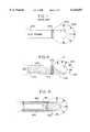
- FIG. 1is a side of view a probe with a conventional sheath
- FIG. 2is a side view of a probe with a sheath, which includes a sack, according to the first embodiment of the present invention
- FIG. 3is a side view of the probe with the sack expanded according to the first embodiment of the present invention
- FIG. 4is a magnified, frontal cross-sectional view of the probe and the expanded sack according to the first embodiment of the present invention
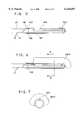
- FIG. 5is a side view of a probe with a sheath, which includes two layers, according to the second embodiment of the present invention.
- FIG. 6is a side view of the probe with one of the layers of the sheath expanded according to the second embodiment of the present invention.
- FIG. 7is a frontal cross-sectional view of the probe and the expanded one of the layers of the sheath according to the second embodiment of the present invention.
- FIG. 8is a side view of a probe with an interface control system (ICS) according to the third embodiment of the present invention.
- FIG. 9is a bottom view of the probe with the ICS according to the third embodiment of the present invention.
- a first preferred embodiment of the present inventionincludes a probe 101, a sheath 105 designed to snugly fit over the probe 101, and a fluid introduction tube 111.
- the probe 101has a cylindrical body and includes one or more ultrasound transducers 103 which transmit and receive ultrasound waves for generating images of tissues.
- the diameter of the probe 101is approximately 2 cm, and the probe length can be up to 10 cm.
- Different parts of the probe 101are designated with appropriate names in order to accurately describe the present invention, as the following: a transducer region 107 includes a surface area of the probe 101 in which the ultrasound transducer 103 is positioned and which allows unobstructed paths for ultrasound waves emanating from the ultrasound transducer 103 to the tissues and for waves reflecting back from the tissues to the ultrasound transducer 103; an underside region 113 is a surface area of the probe 101 located at the diametrically opposite side from the ultrasound transducer 103 on the probe 101; a tip 104 is the apex of the probe 101; a leading portion includes the tip 104, the transducer region 107 and the underside region 113 of the probe; and a longitudinal plane (see reference numeral 127 in FIG. 4) is an imaginary plane
- the sheath 105includes a patch 106 affixed thereon by a liquid tight seal, thereby forming a liquid tight sack with an opening 109, a fluid introduction port, to receive the fluid introduction tube 111.
- the patch 106is affixed to an area of the sheath 105 which corresponds in location to the transducer region 107 when the probe 101 is placed inside the sheath 105.
- the liquid tight seal between the patch 106 and the sheath 105is achieved by gluing the patch 106 over the sheath 105. It should be noted, however, other similar methods of affixing the patch 106 onto the sheath 105, such as a heat treatment welding, solvent bonding, molding and adhesive bonding, are contemplated within the present invention.
- the patch 106is, preferably, made of a more elastic material than that of the sheath.
- the elastic material of which the patch 106 is madecan be identical to the material of which the sheath 105 is made.
- the sheath 105is fastened to the probe 101 by a band 102.
- other known method of fastening the sheath 105 to the probe 101can be utilized, i.e., taping, strapping.
- the fluid introduction tube 111is connected to a pump and a valve (not shown in the figures) such that liquid is introduced into or withdrawn from the sack.
- the patch 106aexpands as illustrated in FIG. 3. Therefore, when the ultrasound transducer 103 is placed at a location to collect images of a tissue, the patch 106 can be expanded to form a liquid interface between the ultrasound transducer 103 and the tissue to be imaged. This liquid interface provides clear transmission paths for ultrasound waves emanating from the ultrasound transducer to the tissue to be imaged and for waves reflecting from the tissue back to the ultrasound transducer.
- the interfacealso places the transducer to be located at an adjustable distance from the tissue being imaged, thereby permitting the optimum focal length for the ultrasound transducer 103 to be achieved.
- These two goals in generating clear and undistorted images by the ultrasound transducerare achieved more readily using the present invention because the liquid introduced into the sack is not diverted into a circumferentially expanding the sack and filled into the underside 113 of the probe 101.
- the patch 106preferably covers the transducer region 107 when the probe 101 is placed into the sheath, as discussed above.
- the patch 106can also cover other areas outside of the transducer region 107 on the probe, as long as the goal of controlling the interface is not lost by including too much of other areas or by not covering the transducer region 107.
- the seal between the sheath 105 and the patch 106is preferably formed from the tip 104 of the probe 101 to the end of the of leading region along a longitudinal plane.
- a radius of the probe 123is defined as the distance from the center of the probe 121 to an outer surface of the probe, which is also designated as R, which is approximately 1 cm.
- a plurality of imaginary longitudinal planesare provided which runs the length of the probe 101.
- a top longitudinal plane 125is a longitudinal plane tangential to the surface of the probe 101 where the ultrasound transducer 103 is located.
- Longitudinal planes designated with reference numerals 127 and 129represent longitudinal planes located on the range of 2/5 R to 8/5 R from the top longitudinal plane 125.
- a longitudinal plane 131 that delineates the sealis located within this range.
- the location of the sealis defined, in part, by any longitudinal plane within the range of 2/5 R to 8/5 R from the top surface of the probe 101.
- the locations of the sealform an arc 122 viewed from the cross-sectional view of the probe as illustrated in FIG. 4.
- the arc 122preferably has its angle on the range of 90°-200°. It should be understood that the locations of the seal are preferably completed in such a way that when the sack is expanded to form the interface, the interface covers the ultrasound transducer without causing distortion on the ultrasound waves emanating therefrom.
- the sealtherefore, begins from the tip 104 of the probe where the tip and the longitudinal plane 131 cross each other, follows along the intersection between the longitudinal plane 131 and the outer surface of the probe, and encloses the sack at the other end of the leading portion (see reference numeral 108 in FIG. 2), thereby forming the liquid tight sack 106. It should be noted, however, the actual seal locations do not exactly have to match the intersection between the longitudinal plane 131 and the outer surface of the probe in order to provide a margin of error for manufacturing the sheaths.
- a sheathis provided with two layers, a first and a second layers 141, 143.
- the first and second layersare affixed to each other to form a sack 145 as that of the first embodiment described above.
- a liquidcan be introduced into the sack 145 via its fluid introduction port 147 by the fluid introduction tube 111 in order to expand the sack 145.
- the seals between the two layers 141, 143are created in the substantially same manner as that of the seal in the first embodiment.
- the second sheath layer 143which expands, preferably is made of more elastic material than that of the first sheath layer 141. Also, it should be noted that the first and second layers 141, 143 can be made of same expandable material.
- a third preferred embodiment of the present inventionincludes a sheath 171, an ultrasound probe 170, placed inside the sheath 171, and an interface control system (ICS) 177, a splint which controls the direction to which the sheath 171 expands.
- ICSinterface control system
- the probe 170has a cylindrical body and includes an ultrasound transducer 172 which transmits and receives ultrasound waves for generating images of a tissue.
- the sheath 171 in the third embodiment of this inventionis a conventional sheath which is designed to fit snugly over the probe 170.
- the sheathis secured to the probe 170 by a plurality of bands 173 or o-rings to the probe, thereby forming a liquid tight area 174 into which a liquid can be introduced via a tube (not shown in FIGS. 8-9).
- no fluid introduction portis provided on the sack.
- the probehas a tube therein, which can be used to introduce the liquid into the sack.
- the sheath in this embodimentis prevented from expanding omni-directionally by the ICS 177.
- the ICS 177is made of a rigid material such as nylon, polyethylene, fiber reinforced plastic (or other composite material), polystyrene or the like. It should be noted, however, that any known rigid material that can prevent the sheath 171 from expanding and that can be used in medical examination is contemplated within this invention.
- the ICS 177includes a tongue-like portion 179, a body 181 which includes two arms 183, 185, and grooves 175 to receive at least one o-ring.
- the body 181 with its two arms 183, 185are configured to fit snugly over the probe 170.
- the ICS 177is fastened to the probe by a plurality of o-rings placed over the groove 175 in the ICS 177 and the probe 170.
- other methods of fastening the ICS 177 on to the probe 170such as designing the arms 183, 185 to snap on to the probe 170 or using bands in place of the o-rings, are contemplated within this invention.
- the two arms 183, 185are not an absolute requirement for the present invention. Instead, one continuous body, without the arms, can also be used in an alternative embodiment.
- the tongue-like 179 portionextends from the body 181 of the ICS 177 into the underside region of the leading portion of the probe 170.
- the tongue-like portion 179not only prevents the sheath 171 from expanding omni-directionally but also helps controlling the direction in which the sheath 171 expands.
- the sheath 171is prevented from expanding from the underside region of the probe.
- the shape of the tongueis configured in such a way that when the sheath is expanded to form the interface, the interface covers the ultrasound transducer without causing distortion on the ultrasound waves emanating therefrom.
Landscapes
- Life Sciences & Earth Sciences (AREA)
- Health & Medical Sciences (AREA)
- Physics & Mathematics (AREA)
- Engineering & Computer Science (AREA)
- Heart & Thoracic Surgery (AREA)
- Nuclear Medicine, Radiotherapy & Molecular Imaging (AREA)
- Pathology (AREA)
- Radiology & Medical Imaging (AREA)
- Veterinary Medicine (AREA)
- Biomedical Technology (AREA)
- Biophysics (AREA)
- Medical Informatics (AREA)
- Molecular Biology (AREA)
- Surgery (AREA)
- Animal Behavior & Ethology (AREA)
- General Health & Medical Sciences (AREA)
- Public Health (AREA)
- Acoustics & Sound (AREA)
- Ultra Sonic Daignosis Equipment (AREA)
Abstract
Description
Claims (18)
Priority Applications (1)
| Application Number | Priority Date | Filing Date | Title |
|---|---|---|---|
| US09/184,070US6126607A (en) | 1997-11-03 | 1998-11-02 | Ultrasound interface control system |
Applications Claiming Priority (2)
| Application Number | Priority Date | Filing Date | Title |
|---|---|---|---|
| US6413197P | 1997-11-03 | 1997-11-03 | |
| US09/184,070US6126607A (en) | 1997-11-03 | 1998-11-02 | Ultrasound interface control system |
Publications (1)
| Publication Number | Publication Date |
|---|---|
| US6126607Atrue US6126607A (en) | 2000-10-03 |
Family
ID=22053769
Family Applications (1)
| Application Number | Title | Priority Date | Filing Date |
|---|---|---|---|
| US09/184,070Expired - LifetimeUS6126607A (en) | 1997-11-03 | 1998-11-02 | Ultrasound interface control system |
Country Status (3)
| Country | Link |
|---|---|
| US (1) | US6126607A (en) |
| AU (1) | AU1377699A (en) |
| WO (1) | WO1999022644A1 (en) |
Cited By (53)
| Publication number | Priority date | Publication date | Assignee | Title |
|---|---|---|---|---|
| US6267726B1 (en)* | 1999-10-14 | 2001-07-31 | Peter D. Grimm | Cover for ultrasound probe |
| US6402695B1 (en)* | 1999-10-14 | 2002-06-11 | Peter D. Grimm | Cover for ultrasound probe |
| US20050148863A1 (en)* | 2003-12-09 | 2005-07-07 | Toshiro Okamura | Magnetic fluid detection device |
| US20050261582A1 (en)* | 2004-05-18 | 2005-11-24 | Matthew Becker | Intracorporeal probe with disposable probe body |
| US20060025709A1 (en)* | 2001-07-09 | 2006-02-02 | Civco Medical Instruments Co., Inc. | Tissue warming device and method |
| US20060067467A1 (en)* | 2004-09-28 | 2006-03-30 | Minnesota Medical Physics Llc | Apparatus and method for conformal radiation brachytherapy for breast and other tumors |
| US20070032726A1 (en)* | 2003-05-30 | 2007-02-08 | Takashi Osaka | Ultrasonic probe and ultrasonic elasticity imaging device |
| US20070167824A1 (en)* | 2005-11-30 | 2007-07-19 | Warren Lee | Method of manufacture of catheter tips, including mechanically scanning ultrasound probe catheter tip, and apparatus made by the method |
| US20070232913A1 (en)* | 2006-01-13 | 2007-10-04 | Mirabilis Medica Inc. | Methods and apparatus for the treatment of menometrorrhagia, endometrial pathology, and cervical neoplasia using high intensity focused ultrasound energy |
| US20080194962A1 (en)* | 2007-02-08 | 2008-08-14 | Randall Kevin S | Methods for verifying the integrity of probes for ultrasound imaging systems |
| US20080194963A1 (en)* | 2007-02-08 | 2008-08-14 | Randall Kevin S | Probes for ultrasound imaging systems |
| US20090036773A1 (en)* | 2007-07-31 | 2009-02-05 | Mirabilis Medica Inc. | Methods and apparatus for engagement and coupling of an intracavitory imaging and high intensity focused ultrasound probe |
| US20090088636A1 (en)* | 2006-01-13 | 2009-04-02 | Mirabilis Medica, Inc. | Apparatus for delivering high intensity focused ultrasound energy to a treatment site internal to a patient's body |
| US20090118729A1 (en)* | 2007-11-07 | 2009-05-07 | Mirabilis Medica Inc. | Hemostatic spark erosion tissue tunnel generator with integral treatment providing variable volumetric necrotization of tissue |
| US20090118725A1 (en)* | 2007-11-07 | 2009-05-07 | Mirabilis Medica, Inc. | Hemostatic tissue tunnel generator for inserting treatment apparatus into tissue of a patient |
| US20090326372A1 (en)* | 2008-06-30 | 2009-12-31 | Darlington Gregory | Compound Imaging with HIFU Transducer and Use of Pseudo 3D Imaging |
| US20100036245A1 (en)* | 2005-12-02 | 2010-02-11 | Yan Yu | Image-guided therapy delivery and diagnostic needle system |
| US20100036291A1 (en)* | 2008-08-06 | 2010-02-11 | Mirabilis Medica Inc. | Optimization and feedback control of hifu power deposition through the frequency analysis of backscattered hifu signals |
| US20100036292A1 (en)* | 2008-08-06 | 2010-02-11 | Mirabilis Medica Inc. | Optimization and feedback control of hifu power deposition through the analysis of detected signal characteristics |
| US20100106019A1 (en)* | 2008-10-24 | 2010-04-29 | Mirabilis Medica, Inc. | Method and apparatus for feedback control of hifu treatments |
| US20100113937A1 (en)* | 2006-07-31 | 2010-05-06 | Takeshi Matsumura | Pressing device, and ultrasonic probe and ultrasonic diagnostic apparatus using the pressing device |
| US20100210976A1 (en)* | 2008-10-03 | 2010-08-19 | Mirabilis Medica, Inc. | Method and apparatus for treating tissues with hifu |
| US20100241005A1 (en)* | 2008-10-03 | 2010-09-23 | Mirabilis Medica, Inc. | Office-based system for treating uterine fibroids or other tissues with hifu |
| EP1988833A4 (en)* | 2006-02-17 | 2010-11-17 | Esi Inc | Immersion bag system for use with an ultrasound probe |
| GB2470508A (en)* | 2008-03-05 | 2010-11-24 | Tamarack Habilitation Tech Inc | Seat cushion |
| US20110040190A1 (en)* | 2009-08-17 | 2011-02-17 | Jahnke Russell C | Disposable Acoustic Coupling Medium Container |
| US20110067624A1 (en)* | 2009-09-22 | 2011-03-24 | Cain Charles A | Gel phantoms for testing cavitational ultrasound (histotripsy) transducers |
| WO2013138432A1 (en)* | 2012-03-15 | 2013-09-19 | Civco Medical Instruments Co., Inc. | Ultrasound probe centering device |
| US9049783B2 (en) | 2012-04-13 | 2015-06-02 | Histosonics, Inc. | Systems and methods for obtaining large creepage isolation on printed circuit boards |
| US9144694B2 (en) | 2011-08-10 | 2015-09-29 | The Regents Of The University Of Michigan | Lesion generation through bone using histotripsy therapy without aberration correction |
| US9529080B2 (en) | 2012-12-06 | 2016-12-27 | White Eagle Sonic Technologies, Inc. | System and apparatus having an application programming interface for flexible control of execution ultrasound actions |
| US9530398B2 (en) | 2012-12-06 | 2016-12-27 | White Eagle Sonic Technologies, Inc. | Method for adaptively scheduling ultrasound system actions |
| WO2016207701A1 (en)* | 2015-06-26 | 2016-12-29 | B-K Medical Aps | Ultrasound imaging probe with an instrument channel |
| US9573000B2 (en) | 2010-08-18 | 2017-02-21 | Mirabilis Medica Inc. | HIFU applicator |
| US9636133B2 (en) | 2012-04-30 | 2017-05-02 | The Regents Of The University Of Michigan | Method of manufacturing an ultrasound system |
| US9642634B2 (en) | 2005-09-22 | 2017-05-09 | The Regents Of The University Of Michigan | Pulsed cavitational ultrasound therapy |
| US9901753B2 (en) | 2009-08-26 | 2018-02-27 | The Regents Of The University Of Michigan | Ultrasound lithotripsy and histotripsy for using controlled bubble cloud cavitation in fractionating urinary stones |
| US9943708B2 (en) | 2009-08-26 | 2018-04-17 | Histosonics, Inc. | Automated control of micromanipulator arm for histotripsy prostate therapy while imaging via ultrasound transducers in real time |
| US9983905B2 (en) | 2012-12-06 | 2018-05-29 | White Eagle Sonic Technologies, Inc. | Apparatus and system for real-time execution of ultrasound system actions |
| US10076313B2 (en) | 2012-12-06 | 2018-09-18 | White Eagle Sonic Technologies, Inc. | System and method for automatically adjusting beams to scan an object in a body |
| US10219815B2 (en) | 2005-09-22 | 2019-03-05 | The Regents Of The University Of Michigan | Histotripsy for thrombolysis |
| US10293187B2 (en) | 2013-07-03 | 2019-05-21 | Histosonics, Inc. | Histotripsy excitation sequences optimized for bubble cloud formation using shock scattering |
| US10499884B2 (en) | 2012-12-06 | 2019-12-10 | White Eagle Sonic Technologies, Inc. | System and method for scanning for a second object within a first object using an adaptive scheduler |
| US10780298B2 (en) | 2013-08-22 | 2020-09-22 | The Regents Of The University Of Michigan | Histotripsy using very short monopolar ultrasound pulses |
| US11058399B2 (en) | 2012-10-05 | 2021-07-13 | The Regents Of The University Of Michigan | Bubble-induced color doppler feedback during histotripsy |
| US11122972B2 (en) | 2016-06-16 | 2021-09-21 | Hadasit Medical Research Services And Development Ltd. | Device and method for determination of pupil size in a subject having closed eyelids |
| US11135454B2 (en) | 2015-06-24 | 2021-10-05 | The Regents Of The University Of Michigan | Histotripsy therapy systems and methods for the treatment of brain tissue |
| US11397486B2 (en)* | 2019-08-30 | 2022-07-26 | Apple Inc. | Ultrasonic force detection |
| US11432900B2 (en) | 2013-07-03 | 2022-09-06 | Histosonics, Inc. | Articulating arm limiter for cavitational ultrasound therapy system |
| US11648424B2 (en) | 2018-11-28 | 2023-05-16 | Histosonics Inc. | Histotripsy systems and methods |
| US11813485B2 (en) | 2020-01-28 | 2023-11-14 | The Regents Of The University Of Michigan | Systems and methods for histotripsy immunosensitization |
| US12318636B2 (en) | 2022-10-28 | 2025-06-03 | Histosonics, Inc. | Histotripsy systems and methods |
| US12343568B2 (en) | 2020-08-27 | 2025-07-01 | The Regents Of The University Of Michigan | Ultrasound transducer with transmit-receive capability for histotripsy |
Families Citing this family (1)
| Publication number | Priority date | Publication date | Assignee | Title |
|---|---|---|---|---|
| JP2007536986A (en)* | 2004-05-14 | 2007-12-20 | オムニソニックス メディカル テクノロジーズ インコーポレイテッド | Ultrasonic probe that can be bent using a balloon |
Citations (21)
| Publication number | Priority date | Publication date | Assignee | Title |
|---|---|---|---|---|
| US4579123A (en)* | 1983-12-16 | 1986-04-01 | Hewlett-Packard Company | Stand-off device |
| US4794931A (en)* | 1986-02-28 | 1989-01-03 | Cardiovascular Imaging Systems, Inc. | Catheter apparatus, system and method for intravascular two-dimensional ultrasonography |
| US4815470A (en)* | 1987-11-13 | 1989-03-28 | Advanced Diagnostic Medical Systems, Inc. | Inflatable sheath for ultrasound probe |
| US4911173A (en)* | 1987-11-13 | 1990-03-27 | Diasonics, Inc. | Biopsy attachment for ultrasound probe |
| DE3929612A1 (en)* | 1988-11-22 | 1990-05-31 | Siemens Ag | Intracavitary ultrasonic probe coupler to investigation object - has inner and outer casings with liquid-tight seal forming inner liquid-filled chamber, protective tube |
| US5152294A (en)* | 1989-12-14 | 1992-10-06 | Aloka Co., Ltd. | Three-dimensional ultrasonic scanner |
| US5190046A (en)* | 1992-05-01 | 1993-03-02 | Shturman Cardiology Systems, Inc. | Ultrasound imaging balloon catheter |
| US5199437A (en)* | 1991-09-09 | 1993-04-06 | Sensor Electronics, Inc. | Ultrasonic imager |
| US5201706A (en)* | 1989-05-09 | 1993-04-13 | Toray Industries, Inc. | Catheter with a balloon reinforced with composite yarn |
| US5265612A (en)* | 1992-12-21 | 1993-11-30 | Medical Biophysics International | Intracavity ultrasonic device for elasticity imaging |
| US5331947A (en)* | 1992-05-01 | 1994-07-26 | Shturman Cardiology Systems, Inc. | Inflatable sheath for introduction of ultrasonic catheter through the lumen of a fiber optic endoscope |
| US5335663A (en)* | 1992-12-11 | 1994-08-09 | Tetrad Corporation | Laparoscopic probes and probe sheaths useful in ultrasonic imaging applications |
| US5423332A (en)* | 1993-07-22 | 1995-06-13 | Uromed Corporation | Device and method for determining the mass or volume of a body part |
| US5438997A (en)* | 1991-03-13 | 1995-08-08 | Sieben; Wayne | Intravascular imaging apparatus and methods for use and manufacture |
| US5469853A (en)* | 1992-12-11 | 1995-11-28 | Tetrad Corporation | Bendable ultrasonic probe and sheath for use therewith |
| US5603327A (en)* | 1993-02-01 | 1997-02-18 | Endosonics Corporation | Ultrasound catheter probe |
| US5623940A (en)* | 1994-08-02 | 1997-04-29 | S.L.T. Japan Co., Ltd. | Catheter apparatus with a sensor |
| US5640961A (en)* | 1995-09-25 | 1997-06-24 | Hewlett-Packard Company | Device with aspherical compensation for focusing ultrasound |
| US5671747A (en)* | 1996-01-24 | 1997-09-30 | Hewlett-Packard Company | Ultrasound probe having interchangeable accessories |
| US5672153A (en)* | 1992-08-12 | 1997-09-30 | Vidamed, Inc. | Medical probe device and method |
| US5685839A (en)* | 1982-08-12 | 1997-11-11 | Edwards; Stuart D. | Ultrasound probe with thermal sensing |
- 1998
- 1998-11-02WOPCT/US1998/023392patent/WO1999022644A1/enactiveApplication Filing
- 1998-11-02USUS09/184,070patent/US6126607A/ennot_activeExpired - Lifetime
- 1998-11-02AUAU13776/99Apatent/AU1377699A/ennot_activeAbandoned
Patent Citations (21)
| Publication number | Priority date | Publication date | Assignee | Title |
|---|---|---|---|---|
| US5685839A (en)* | 1982-08-12 | 1997-11-11 | Edwards; Stuart D. | Ultrasound probe with thermal sensing |
| US4579123A (en)* | 1983-12-16 | 1986-04-01 | Hewlett-Packard Company | Stand-off device |
| US4794931A (en)* | 1986-02-28 | 1989-01-03 | Cardiovascular Imaging Systems, Inc. | Catheter apparatus, system and method for intravascular two-dimensional ultrasonography |
| US4815470A (en)* | 1987-11-13 | 1989-03-28 | Advanced Diagnostic Medical Systems, Inc. | Inflatable sheath for ultrasound probe |
| US4911173A (en)* | 1987-11-13 | 1990-03-27 | Diasonics, Inc. | Biopsy attachment for ultrasound probe |
| DE3929612A1 (en)* | 1988-11-22 | 1990-05-31 | Siemens Ag | Intracavitary ultrasonic probe coupler to investigation object - has inner and outer casings with liquid-tight seal forming inner liquid-filled chamber, protective tube |
| US5201706A (en)* | 1989-05-09 | 1993-04-13 | Toray Industries, Inc. | Catheter with a balloon reinforced with composite yarn |
| US5152294A (en)* | 1989-12-14 | 1992-10-06 | Aloka Co., Ltd. | Three-dimensional ultrasonic scanner |
| US5438997A (en)* | 1991-03-13 | 1995-08-08 | Sieben; Wayne | Intravascular imaging apparatus and methods for use and manufacture |
| US5199437A (en)* | 1991-09-09 | 1993-04-06 | Sensor Electronics, Inc. | Ultrasonic imager |
| US5331947A (en)* | 1992-05-01 | 1994-07-26 | Shturman Cardiology Systems, Inc. | Inflatable sheath for introduction of ultrasonic catheter through the lumen of a fiber optic endoscope |
| US5190046A (en)* | 1992-05-01 | 1993-03-02 | Shturman Cardiology Systems, Inc. | Ultrasound imaging balloon catheter |
| US5672153A (en)* | 1992-08-12 | 1997-09-30 | Vidamed, Inc. | Medical probe device and method |
| US5335663A (en)* | 1992-12-11 | 1994-08-09 | Tetrad Corporation | Laparoscopic probes and probe sheaths useful in ultrasonic imaging applications |
| US5469853A (en)* | 1992-12-11 | 1995-11-28 | Tetrad Corporation | Bendable ultrasonic probe and sheath for use therewith |
| US5265612A (en)* | 1992-12-21 | 1993-11-30 | Medical Biophysics International | Intracavity ultrasonic device for elasticity imaging |
| US5603327A (en)* | 1993-02-01 | 1997-02-18 | Endosonics Corporation | Ultrasound catheter probe |
| US5423332A (en)* | 1993-07-22 | 1995-06-13 | Uromed Corporation | Device and method for determining the mass or volume of a body part |
| US5623940A (en)* | 1994-08-02 | 1997-04-29 | S.L.T. Japan Co., Ltd. | Catheter apparatus with a sensor |
| US5640961A (en)* | 1995-09-25 | 1997-06-24 | Hewlett-Packard Company | Device with aspherical compensation for focusing ultrasound |
| US5671747A (en)* | 1996-01-24 | 1997-09-30 | Hewlett-Packard Company | Ultrasound probe having interchangeable accessories |
Cited By (95)
| Publication number | Priority date | Publication date | Assignee | Title |
|---|---|---|---|---|
| US6267726B1 (en)* | 1999-10-14 | 2001-07-31 | Peter D. Grimm | Cover for ultrasound probe |
| US6402695B1 (en)* | 1999-10-14 | 2002-06-11 | Peter D. Grimm | Cover for ultrasound probe |
| US20060025709A1 (en)* | 2001-07-09 | 2006-02-02 | Civco Medical Instruments Co., Inc. | Tissue warming device and method |
| US7563260B2 (en) | 2001-07-09 | 2009-07-21 | Civco Medical Instruments Co., Inc. | Tissue warming device and method |
| US20070032726A1 (en)* | 2003-05-30 | 2007-02-08 | Takashi Osaka | Ultrasonic probe and ultrasonic elasticity imaging device |
| US7914456B2 (en)* | 2003-05-30 | 2011-03-29 | Hitachi Medical Corporation | Ultrasonic probe and ultrasonic elasticity imaging device |
| US20050148863A1 (en)* | 2003-12-09 | 2005-07-07 | Toshiro Okamura | Magnetic fluid detection device |
| US20050261582A1 (en)* | 2004-05-18 | 2005-11-24 | Matthew Becker | Intracorporeal probe with disposable probe body |
| US20060067467A1 (en)* | 2004-09-28 | 2006-03-30 | Minnesota Medical Physics Llc | Apparatus and method for conformal radiation brachytherapy for breast and other tumors |
| US9642634B2 (en) | 2005-09-22 | 2017-05-09 | The Regents Of The University Of Michigan | Pulsed cavitational ultrasound therapy |
| US11364042B2 (en) | 2005-09-22 | 2022-06-21 | The Regents Of The University Of Michigan | Histotripsy for thrombolysis |
| US11701134B2 (en) | 2005-09-22 | 2023-07-18 | The Regents Of The University Of Michigan | Histotripsy for thrombolysis |
| US12303152B2 (en) | 2005-09-22 | 2025-05-20 | The Regents Of The University Of Michigan | Histotripsy for thrombolysis |
| US10219815B2 (en) | 2005-09-22 | 2019-03-05 | The Regents Of The University Of Michigan | Histotripsy for thrombolysis |
| US12150661B2 (en) | 2005-09-22 | 2024-11-26 | The Regents Of The University Of Michigan | Histotripsy for thrombolysis |
| US20070167824A1 (en)* | 2005-11-30 | 2007-07-19 | Warren Lee | Method of manufacture of catheter tips, including mechanically scanning ultrasound probe catheter tip, and apparatus made by the method |
| US20100036245A1 (en)* | 2005-12-02 | 2010-02-11 | Yan Yu | Image-guided therapy delivery and diagnostic needle system |
| US9114252B2 (en)* | 2005-12-02 | 2015-08-25 | University Of Rochester | Image-guided therapy delivery and diagnostic needle system |
| US20070232913A1 (en)* | 2006-01-13 | 2007-10-04 | Mirabilis Medica Inc. | Methods and apparatus for the treatment of menometrorrhagia, endometrial pathology, and cervical neoplasia using high intensity focused ultrasound energy |
| US8057391B2 (en) | 2006-01-13 | 2011-11-15 | Mirabilis Medica, Inc. | Apparatus for delivering high intensity focused ultrasound energy to a treatment site internal to a patient's body |
| US8277379B2 (en) | 2006-01-13 | 2012-10-02 | Mirabilis Medica Inc. | Methods and apparatus for the treatment of menometrorrhagia, endometrial pathology, and cervical neoplasia using high intensity focused ultrasound energy |
| US20090088636A1 (en)* | 2006-01-13 | 2009-04-02 | Mirabilis Medica, Inc. | Apparatus for delivering high intensity focused ultrasound energy to a treatment site internal to a patient's body |
| EP1988833A4 (en)* | 2006-02-17 | 2010-11-17 | Esi Inc | Immersion bag system for use with an ultrasound probe |
| JP5237808B2 (en)* | 2006-07-31 | 2013-07-17 | 株式会社日立メディコ | COMPRESSION DEVICE AND ULTRASONIC PROBE AND ULTRASONIC DIAGNOSTIC DEVICE USING THE COMPRESSION DEVICE |
| US20100113937A1 (en)* | 2006-07-31 | 2010-05-06 | Takeshi Matsumura | Pressing device, and ultrasonic probe and ultrasonic diagnostic apparatus using the pressing device |
| US8747323B2 (en)* | 2006-07-31 | 2014-06-10 | Hitachi Medical Corporation | Pressing device, and ultrasonic probe and ultrasonic diagnostic apparatus using the pressing device |
| WO2008097488A3 (en)* | 2007-02-08 | 2008-11-27 | Penrith Corp | Methods for verifying the integrity of probes for ultrasound imaging systems |
| US7891230B2 (en) | 2007-02-08 | 2011-02-22 | Penrith Corporation | Methods for verifying the integrity of probes for ultrasound imaging systems |
| US20080194962A1 (en)* | 2007-02-08 | 2008-08-14 | Randall Kevin S | Methods for verifying the integrity of probes for ultrasound imaging systems |
| US20080194963A1 (en)* | 2007-02-08 | 2008-08-14 | Randall Kevin S | Probes for ultrasound imaging systems |
| US20090036773A1 (en)* | 2007-07-31 | 2009-02-05 | Mirabilis Medica Inc. | Methods and apparatus for engagement and coupling of an intracavitory imaging and high intensity focused ultrasound probe |
| US8052604B2 (en)* | 2007-07-31 | 2011-11-08 | Mirabilis Medica Inc. | Methods and apparatus for engagement and coupling of an intracavitory imaging and high intensity focused ultrasound probe |
| US20090118729A1 (en)* | 2007-11-07 | 2009-05-07 | Mirabilis Medica Inc. | Hemostatic spark erosion tissue tunnel generator with integral treatment providing variable volumetric necrotization of tissue |
| US8187270B2 (en) | 2007-11-07 | 2012-05-29 | Mirabilis Medica Inc. | Hemostatic spark erosion tissue tunnel generator with integral treatment providing variable volumetric necrotization of tissue |
| US8439907B2 (en) | 2007-11-07 | 2013-05-14 | Mirabilis Medica Inc. | Hemostatic tissue tunnel generator for inserting treatment apparatus into tissue of a patient |
| US20090118725A1 (en)* | 2007-11-07 | 2009-05-07 | Mirabilis Medica, Inc. | Hemostatic tissue tunnel generator for inserting treatment apparatus into tissue of a patient |
| GB2470508B (en)* | 2008-03-05 | 2012-04-04 | Tamarack Habilitation Tech Inc | Seat cushion |
| GB2470508A (en)* | 2008-03-05 | 2010-11-24 | Tamarack Habilitation Tech Inc | Seat cushion |
| US20090326372A1 (en)* | 2008-06-30 | 2009-12-31 | Darlington Gregory | Compound Imaging with HIFU Transducer and Use of Pseudo 3D Imaging |
| US8216161B2 (en) | 2008-08-06 | 2012-07-10 | Mirabilis Medica Inc. | Optimization and feedback control of HIFU power deposition through the frequency analysis of backscattered HIFU signals |
| US20100036291A1 (en)* | 2008-08-06 | 2010-02-11 | Mirabilis Medica Inc. | Optimization and feedback control of hifu power deposition through the frequency analysis of backscattered hifu signals |
| US9248318B2 (en) | 2008-08-06 | 2016-02-02 | Mirabilis Medica Inc. | Optimization and feedback control of HIFU power deposition through the analysis of detected signal characteristics |
| US20100036292A1 (en)* | 2008-08-06 | 2010-02-11 | Mirabilis Medica Inc. | Optimization and feedback control of hifu power deposition through the analysis of detected signal characteristics |
| US10226646B2 (en) | 2008-08-06 | 2019-03-12 | Mirabillis Medica, Inc. | Optimization and feedback control of HIFU power deposition through the analysis of detected signal characteristics |
| US9050449B2 (en) | 2008-10-03 | 2015-06-09 | Mirabilis Medica, Inc. | System for treating a volume of tissue with high intensity focused ultrasound |
| US8845559B2 (en) | 2008-10-03 | 2014-09-30 | Mirabilis Medica Inc. | Method and apparatus for treating tissues with HIFU |
| US9770605B2 (en) | 2008-10-03 | 2017-09-26 | Mirabilis Medica, Inc. | System for treating a volume of tissue with high intensity focused ultrasound |
| US20100210976A1 (en)* | 2008-10-03 | 2010-08-19 | Mirabilis Medica, Inc. | Method and apparatus for treating tissues with hifu |
| US20100241005A1 (en)* | 2008-10-03 | 2010-09-23 | Mirabilis Medica, Inc. | Office-based system for treating uterine fibroids or other tissues with hifu |
| US8480600B2 (en) | 2008-10-24 | 2013-07-09 | Mirabilis Medica Inc. | Method and apparatus for feedback control of HIFU treatments |
| US20100106019A1 (en)* | 2008-10-24 | 2010-04-29 | Mirabilis Medica, Inc. | Method and apparatus for feedback control of hifu treatments |
| US20110040190A1 (en)* | 2009-08-17 | 2011-02-17 | Jahnke Russell C | Disposable Acoustic Coupling Medium Container |
| US9061131B2 (en)* | 2009-08-17 | 2015-06-23 | Histosonics, Inc. | Disposable acoustic coupling medium container |
| US9526923B2 (en) | 2009-08-17 | 2016-12-27 | Histosonics, Inc. | Disposable acoustic coupling medium container |
| US9943708B2 (en) | 2009-08-26 | 2018-04-17 | Histosonics, Inc. | Automated control of micromanipulator arm for histotripsy prostate therapy while imaging via ultrasound transducers in real time |
| US9901753B2 (en) | 2009-08-26 | 2018-02-27 | The Regents Of The University Of Michigan | Ultrasound lithotripsy and histotripsy for using controlled bubble cloud cavitation in fractionating urinary stones |
| US8539813B2 (en) | 2009-09-22 | 2013-09-24 | The Regents Of The University Of Michigan | Gel phantoms for testing cavitational ultrasound (histotripsy) transducers |
| US20110067624A1 (en)* | 2009-09-22 | 2011-03-24 | Cain Charles A | Gel phantoms for testing cavitational ultrasound (histotripsy) transducers |
| US9573000B2 (en) | 2010-08-18 | 2017-02-21 | Mirabilis Medica Inc. | HIFU applicator |
| US10071266B2 (en) | 2011-08-10 | 2018-09-11 | The Regents Of The University Of Michigan | Lesion generation through bone using histotripsy therapy without aberration correction |
| US9144694B2 (en) | 2011-08-10 | 2015-09-29 | The Regents Of The University Of Michigan | Lesion generation through bone using histotripsy therapy without aberration correction |
| WO2013138432A1 (en)* | 2012-03-15 | 2013-09-19 | Civco Medical Instruments Co., Inc. | Ultrasound probe centering device |
| US9049783B2 (en) | 2012-04-13 | 2015-06-02 | Histosonics, Inc. | Systems and methods for obtaining large creepage isolation on printed circuit boards |
| US9636133B2 (en) | 2012-04-30 | 2017-05-02 | The Regents Of The University Of Michigan | Method of manufacturing an ultrasound system |
| US11058399B2 (en) | 2012-10-05 | 2021-07-13 | The Regents Of The University Of Michigan | Bubble-induced color doppler feedback during histotripsy |
| US10499884B2 (en) | 2012-12-06 | 2019-12-10 | White Eagle Sonic Technologies, Inc. | System and method for scanning for a second object within a first object using an adaptive scheduler |
| US9773496B2 (en) | 2012-12-06 | 2017-09-26 | White Eagle Sonic Technologies, Inc. | Apparatus and system for adaptively scheduling ultrasound system actions |
| US11883242B2 (en) | 2012-12-06 | 2024-01-30 | White Eagle Sonic Technologies, Inc. | System and method for scanning for a second object within a first object using an adaptive scheduler |
| US10076313B2 (en) | 2012-12-06 | 2018-09-18 | White Eagle Sonic Technologies, Inc. | System and method for automatically adjusting beams to scan an object in a body |
| US9530398B2 (en) | 2012-12-06 | 2016-12-27 | White Eagle Sonic Technologies, Inc. | Method for adaptively scheduling ultrasound system actions |
| US9983905B2 (en) | 2012-12-06 | 2018-05-29 | White Eagle Sonic Technologies, Inc. | Apparatus and system for real-time execution of ultrasound system actions |
| US12251269B2 (en) | 2012-12-06 | 2025-03-18 | White Eagle Sonic Technologies, Inc. | System and method for scanning for a second object within a first object using an adaptive scheduler |
| US11490878B2 (en) | 2012-12-06 | 2022-11-08 | White Eagle Sonic Technologies, Inc. | System and method for scanning for a second object within a first object using an adaptive scheduler |
| US10235988B2 (en) | 2012-12-06 | 2019-03-19 | White Eagle Sonic Technologies, Inc. | Apparatus and system for adaptively scheduling ultrasound system actions |
| US9529080B2 (en) | 2012-12-06 | 2016-12-27 | White Eagle Sonic Technologies, Inc. | System and apparatus having an application programming interface for flexible control of execution ultrasound actions |
| US11432900B2 (en) | 2013-07-03 | 2022-09-06 | Histosonics, Inc. | Articulating arm limiter for cavitational ultrasound therapy system |
| US10293187B2 (en) | 2013-07-03 | 2019-05-21 | Histosonics, Inc. | Histotripsy excitation sequences optimized for bubble cloud formation using shock scattering |
| US11819712B2 (en) | 2013-08-22 | 2023-11-21 | The Regents Of The University Of Michigan | Histotripsy using very short ultrasound pulses |
| US12350525B2 (en) | 2013-08-22 | 2025-07-08 | The Regents Of The University Of Michigan | Histotripsy using very short ultrasound pulses |
| US10780298B2 (en) | 2013-08-22 | 2020-09-22 | The Regents Of The University Of Michigan | Histotripsy using very short monopolar ultrasound pulses |
| US11135454B2 (en) | 2015-06-24 | 2021-10-05 | The Regents Of The University Of Michigan | Histotripsy therapy systems and methods for the treatment of brain tissue |
| US12220602B2 (en) | 2015-06-24 | 2025-02-11 | The Regents Of The University Of Michigan | Histotripsy therapy systems and methods for the treatment of brain tissue |
| US11246566B2 (en)* | 2015-06-26 | 2022-02-15 | B-K Medical Aps | US imaging probe with an instrument channel |
| WO2016207701A1 (en)* | 2015-06-26 | 2016-12-29 | B-K Medical Aps | Ultrasound imaging probe with an instrument channel |
| US11684255B2 (en) | 2016-06-16 | 2023-06-27 | Yissum Research Development Company Of The Hebrew University Of Jerusalem Ltd. | Device and method for determination of pupil size in a subject having closed eyelids |
| US11122972B2 (en) | 2016-06-16 | 2021-09-21 | Hadasit Medical Research Services And Development Ltd. | Device and method for determination of pupil size in a subject having closed eyelids |
| US11813484B2 (en) | 2018-11-28 | 2023-11-14 | Histosonics, Inc. | Histotripsy systems and methods |
| US11980778B2 (en) | 2018-11-28 | 2024-05-14 | Histosonics, Inc. | Histotripsy systems and methods |
| US11648424B2 (en) | 2018-11-28 | 2023-05-16 | Histosonics Inc. | Histotripsy systems and methods |
| US12420118B2 (en) | 2018-11-28 | 2025-09-23 | Histosonics, Inc. | Histotripsy systems and methods |
| US11397486B2 (en)* | 2019-08-30 | 2022-07-26 | Apple Inc. | Ultrasonic force detection |
| US11813485B2 (en) | 2020-01-28 | 2023-11-14 | The Regents Of The University Of Michigan | Systems and methods for histotripsy immunosensitization |
| US12343568B2 (en) | 2020-08-27 | 2025-07-01 | The Regents Of The University Of Michigan | Ultrasound transducer with transmit-receive capability for histotripsy |
| US12318636B2 (en) | 2022-10-28 | 2025-06-03 | Histosonics, Inc. | Histotripsy systems and methods |
| US12390665B1 (en) | 2022-10-28 | 2025-08-19 | Histosonics, Inc. | Histotripsy systems and methods |
Also Published As
| Publication number | Publication date |
|---|---|
| WO1999022644A1 (en) | 1999-05-14 |
| AU1377699A (en) | 1999-05-24 |
Similar Documents
| Publication | Publication Date | Title |
|---|---|---|
| US6126607A (en) | Ultrasound interface control system | |
| US6306097B1 (en) | Ultrasound imaging catheter guiding assembly with catheter working port | |
| ES2221666T3 (en) | ULTRASOUND EMISSION SYSTEM FOR THERAPEUTIC USE. | |
| US7377900B2 (en) | Endo-cavity focused ultrasound transducer | |
| US5762066A (en) | Multifaceted ultrasound transducer probe system and methods for its use | |
| US7883468B2 (en) | Medical system having an ultrasound source and an acoustic coupling medium | |
| EP1397074B1 (en) | Tissue-retaining system for ultrasound medical treatment | |
| CN101227860B (en) | Imaging and treatment head for living organs and method of manufacture | |
| CN1764419A (en) | Cardiac ablation devices | |
| KR20120101661A (en) | A cover, a treatment device and a method of use of such a device | |
| AU2002312085A1 (en) | Tissue-retaining system for ultrasound medical treatment | |
| US6716176B1 (en) | Device for use in temporary insertion of a sensor within a patient's body | |
| US6302857B1 (en) | Method and apparatus for lowering audible noise emissions from lithotriptors | |
| JP2003235847A (en) | Ultrasonic examination apparatus | |
| AU2002312083B2 (en) | Treatment of lung lesions using ultrasound | |
| JPH05285141A (en) | Balloon sheath for ultrasonic probe | |
| AU2002305713A1 (en) | Ultrasound feedback in medically-treated patients | |
| AU2002312083A1 (en) | Treatment of lung lesions using ultrasound |
Legal Events
| Date | Code | Title | Description |
|---|---|---|---|
| AS | Assignment | Owner name:BARZELL-WHITMORE MAROON BELLS, INC., FLORIDA Free format text:ASSIGNMENT OF ASSIGNORS INTEREST;ASSIGNORS:WHITMORE, III, WILLET F.;BARZELL, WINSTON E.;REEL/FRAME:009637/0408 Effective date:19981204 | |
| AS | Assignment | Owner name:MADISON CAPITAL FUNDING LLC, AS AGENT, ILLINOIS Free format text:SECURITY AGREEMENT;ASSIGNOR:BARZELL WHITMORE MAROON BELLS, INC.;REEL/FRAME:014289/0917 Effective date:20030718 | |
| FEPP | Fee payment procedure | Free format text:PAYOR NUMBER ASSIGNED (ORIGINAL EVENT CODE: ASPN); ENTITY STATUS OF PATENT OWNER: LARGE ENTITY | |
| REMI | Maintenance fee reminder mailed | ||
| REIN | Reinstatement after maintenance fee payment confirmed | ||
| FP | Lapsed due to failure to pay maintenance fee | Effective date:20041003 | |
| FEPP | Fee payment procedure | Free format text:PETITION RELATED TO MAINTENANCE FEES FILED (ORIGINAL EVENT CODE: PMFP); ENTITY STATUS OF PATENT OWNER: LARGE ENTITY | |
| FPAY | Fee payment | Year of fee payment:4 | |
| SULP | Surcharge for late payment | ||
| PRDP | Patent reinstated due to the acceptance of a late maintenance fee | Effective date:20050323 | |
| STCF | Information on status: patent grant | Free format text:PATENTED CASE | |
| REMI | Maintenance fee reminder mailed | ||
| FPAY | Fee payment | Year of fee payment:8 | |
| SULP | Surcharge for late payment | Year of fee payment:7 | |
| FEPP | Fee payment procedure | Free format text:PAYER NUMBER DE-ASSIGNED (ORIGINAL EVENT CODE: RMPN); ENTITY STATUS OF PATENT OWNER: LARGE ENTITY Free format text:PAYOR NUMBER ASSIGNED (ORIGINAL EVENT CODE: ASPN); ENTITY STATUS OF PATENT OWNER: LARGE ENTITY | |
| AS | Assignment | Owner name:CIVCO MEDICAL INSTRUMENTS CO., INC., IOWA Free format text:ASSIGNMENT OF ASSIGNORS INTEREST;ASSIGNOR:BARZELL WHITMORE MAROON BELLS, INC. A/K/A BARZELL-WHITMORE MAROON BELLS, INC.;REEL/FRAME:025504/0596 Effective date:20070913 | |
| FPAY | Fee payment | Year of fee payment:12 |