US6126602A - Phased array acoustic systems with intra-group processors - Google Patents
Phased array acoustic systems with intra-group processorsDownload PDFInfo
- Publication number
- US6126602A US6126602AUS09/398,353US39835399AUS6126602AUS 6126602 AUS6126602 AUS 6126602AUS 39835399 AUS39835399 AUS 39835399AUS 6126602 AUS6126602 AUS 6126602A
- Authority
- US
- United States
- Prior art keywords
- receive
- intra
- constructed
- transmit
- delay
- Prior art date
- Legal status (The legal status is an assumption and is not a legal conclusion. Google has not performed a legal analysis and makes no representation as to the accuracy of the status listed.)
- Expired - Lifetime
Links
Images


Classifications
- G—PHYSICS
- G01—MEASURING; TESTING
- G01S—RADIO DIRECTION-FINDING; RADIO NAVIGATION; DETERMINING DISTANCE OR VELOCITY BY USE OF RADIO WAVES; LOCATING OR PRESENCE-DETECTING BY USE OF THE REFLECTION OR RERADIATION OF RADIO WAVES; ANALOGOUS ARRANGEMENTS USING OTHER WAVES
- G01S15/00—Systems using the reflection or reradiation of acoustic waves, e.g. sonar systems
- G01S15/88—Sonar systems specially adapted for specific applications
- G01S15/89—Sonar systems specially adapted for specific applications for mapping or imaging
- G01S15/8906—Short-range imaging systems; Acoustic microscope systems using pulse-echo techniques
- G01S15/8909—Short-range imaging systems; Acoustic microscope systems using pulse-echo techniques using a static transducer configuration
- G01S15/8915—Short-range imaging systems; Acoustic microscope systems using pulse-echo techniques using a static transducer configuration using a transducer array
- G01S15/8925—Short-range imaging systems; Acoustic microscope systems using pulse-echo techniques using a static transducer configuration using a transducer array the array being a two-dimensional transducer configuration, i.e. matrix or orthogonal linear arrays
- A—HUMAN NECESSITIES
- A61—MEDICAL OR VETERINARY SCIENCE; HYGIENE
- A61B—DIAGNOSIS; SURGERY; IDENTIFICATION
- A61B8/00—Diagnosis using ultrasonic, sonic or infrasonic waves
- A61B8/44—Constructional features of the ultrasonic, sonic or infrasonic diagnostic device
- A61B8/4483—Constructional features of the ultrasonic, sonic or infrasonic diagnostic device characterised by features of the ultrasound transducer
- A61B8/4488—Constructional features of the ultrasonic, sonic or infrasonic diagnostic device characterised by features of the ultrasound transducer the transducer being a phased array
- A—HUMAN NECESSITIES
- A61—MEDICAL OR VETERINARY SCIENCE; HYGIENE
- A61B—DIAGNOSIS; SURGERY; IDENTIFICATION
- A61B8/00—Diagnosis using ultrasonic, sonic or infrasonic waves
- A61B8/44—Constructional features of the ultrasonic, sonic or infrasonic diagnostic device
- A61B8/4483—Constructional features of the ultrasonic, sonic or infrasonic diagnostic device characterised by features of the ultrasound transducer
- A61B8/4494—Constructional features of the ultrasonic, sonic or infrasonic diagnostic device characterised by features of the ultrasound transducer characterised by the arrangement of the transducer elements
- G—PHYSICS
- G01—MEASURING; TESTING
- G01S—RADIO DIRECTION-FINDING; RADIO NAVIGATION; DETERMINING DISTANCE OR VELOCITY BY USE OF RADIO WAVES; LOCATING OR PRESENCE-DETECTING BY USE OF THE REFLECTION OR RERADIATION OF RADIO WAVES; ANALOGOUS ARRANGEMENTS USING OTHER WAVES
- G01S15/00—Systems using the reflection or reradiation of acoustic waves, e.g. sonar systems
- G01S15/88—Sonar systems specially adapted for specific applications
- G01S15/89—Sonar systems specially adapted for specific applications for mapping or imaging
- G01S15/8906—Short-range imaging systems; Acoustic microscope systems using pulse-echo techniques
- G01S15/8909—Short-range imaging systems; Acoustic microscope systems using pulse-echo techniques using a static transducer configuration
- G01S15/8915—Short-range imaging systems; Acoustic microscope systems using pulse-echo techniques using a static transducer configuration using a transducer array
- G01S15/8927—Short-range imaging systems; Acoustic microscope systems using pulse-echo techniques using a static transducer configuration using a transducer array using simultaneously or sequentially two or more subarrays or subapertures
- G—PHYSICS
- G01—MEASURING; TESTING
- G01S—RADIO DIRECTION-FINDING; RADIO NAVIGATION; DETERMINING DISTANCE OR VELOCITY BY USE OF RADIO WAVES; LOCATING OR PRESENCE-DETECTING BY USE OF THE REFLECTION OR RERADIATION OF RADIO WAVES; ANALOGOUS ARRANGEMENTS USING OTHER WAVES
- G01S7/00—Details of systems according to groups G01S13/00, G01S15/00, G01S17/00
- G01S7/52—Details of systems according to groups G01S13/00, G01S15/00, G01S17/00 of systems according to group G01S15/00
- G01S7/52017—Details of systems according to groups G01S13/00, G01S15/00, G01S17/00 of systems according to group G01S15/00 particularly adapted to short-range imaging
- G01S7/52019—Details of transmitters
- G01S7/5202—Details of transmitters for pulse systems
- G—PHYSICS
- G01—MEASURING; TESTING
- G01S—RADIO DIRECTION-FINDING; RADIO NAVIGATION; DETERMINING DISTANCE OR VELOCITY BY USE OF RADIO WAVES; LOCATING OR PRESENCE-DETECTING BY USE OF THE REFLECTION OR RERADIATION OF RADIO WAVES; ANALOGOUS ARRANGEMENTS USING OTHER WAVES
- G01S7/00—Details of systems according to groups G01S13/00, G01S15/00, G01S17/00
- G01S7/52—Details of systems according to groups G01S13/00, G01S15/00, G01S17/00 of systems according to group G01S15/00
- G01S7/52017—Details of systems according to groups G01S13/00, G01S15/00, G01S17/00 of systems according to group G01S15/00 particularly adapted to short-range imaging
- G01S7/52046—Techniques for image enhancement involving transmitter or receiver
- G—PHYSICS
- G01—MEASURING; TESTING
- G01S—RADIO DIRECTION-FINDING; RADIO NAVIGATION; DETERMINING DISTANCE OR VELOCITY BY USE OF RADIO WAVES; LOCATING OR PRESENCE-DETECTING BY USE OF THE REFLECTION OR RERADIATION OF RADIO WAVES; ANALOGOUS ARRANGEMENTS USING OTHER WAVES
- G01S7/00—Details of systems according to groups G01S13/00, G01S15/00, G01S17/00
- G01S7/52—Details of systems according to groups G01S13/00, G01S15/00, G01S17/00 of systems according to group G01S15/00
- G01S7/52017—Details of systems according to groups G01S13/00, G01S15/00, G01S17/00 of systems according to group G01S15/00 particularly adapted to short-range imaging
- G01S7/52079—Constructional features
- G01S7/5208—Constructional features with integration of processing functions inside probe or scanhead
- G—PHYSICS
- G10—MUSICAL INSTRUMENTS; ACOUSTICS
- G10K—SOUND-PRODUCING DEVICES; METHODS OR DEVICES FOR PROTECTING AGAINST, OR FOR DAMPING, NOISE OR OTHER ACOUSTIC WAVES IN GENERAL; ACOUSTICS NOT OTHERWISE PROVIDED FOR
- G10K11/00—Methods or devices for transmitting, conducting or directing sound in general; Methods or devices for protecting against, or for damping, noise or other acoustic waves in general
- G10K11/18—Methods or devices for transmitting, conducting or directing sound
- G10K11/26—Sound-focusing or directing, e.g. scanning
- G10K11/34—Sound-focusing or directing, e.g. scanning using electrical steering of transducer arrays, e.g. beam steering
- G10K11/341—Circuits therefor
- G10K11/346—Circuits therefor using phase variation
- A—HUMAN NECESSITIES
- A61—MEDICAL OR VETERINARY SCIENCE; HYGIENE
- A61B—DIAGNOSIS; SURGERY; IDENTIFICATION
- A61B8/00—Diagnosis using ultrasonic, sonic or infrasonic waves
- A61B8/08—Clinical applications
- A—HUMAN NECESSITIES
- A61—MEDICAL OR VETERINARY SCIENCE; HYGIENE
- A61B—DIAGNOSIS; SURGERY; IDENTIFICATION
- A61B8/00—Diagnosis using ultrasonic, sonic or infrasonic waves
- A61B8/48—Diagnostic techniques
- A61B8/483—Diagnostic techniques involving the acquisition of a 3D volume of data
- G—PHYSICS
- G01—MEASURING; TESTING
- G01S—RADIO DIRECTION-FINDING; RADIO NAVIGATION; DETERMINING DISTANCE OR VELOCITY BY USE OF RADIO WAVES; LOCATING OR PRESENCE-DETECTING BY USE OF THE REFLECTION OR RERADIATION OF RADIO WAVES; ANALOGOUS ARRANGEMENTS USING OTHER WAVES
- G01S15/00—Systems using the reflection or reradiation of acoustic waves, e.g. sonar systems
- G01S15/88—Sonar systems specially adapted for specific applications
- G01S15/89—Sonar systems specially adapted for specific applications for mapping or imaging
- G01S15/8906—Short-range imaging systems; Acoustic microscope systems using pulse-echo techniques
- G01S15/899—Combination of imaging systems with ancillary equipment
- G—PHYSICS
- G01—MEASURING; TESTING
- G01S—RADIO DIRECTION-FINDING; RADIO NAVIGATION; DETERMINING DISTANCE OR VELOCITY BY USE OF RADIO WAVES; LOCATING OR PRESENCE-DETECTING BY USE OF THE REFLECTION OR RERADIATION OF RADIO WAVES; ANALOGOUS ARRANGEMENTS USING OTHER WAVES
- G01S7/00—Details of systems according to groups G01S13/00, G01S15/00, G01S17/00
- G01S7/52—Details of systems according to groups G01S13/00, G01S15/00, G01S17/00 of systems according to group G01S15/00
- G01S7/52017—Details of systems according to groups G01S13/00, G01S15/00, G01S17/00 of systems according to group G01S15/00 particularly adapted to short-range imaging
- G01S7/52023—Details of receivers
Definitions
- This inventionrelates to ultrasound, phased array imaging systems and, more particularly, to imaging systems that use a transducer array with a very large number of transducer elements. This invention also relates to imaging systems that include a transducer array with a larger number of transducer elements than beamformer channels.
- Phased array ultrasonic imaging systemshave been used to produce real-time images of internal portions of the human body.
- Such imaging systemsinclude a multiple channel transmit beamformer and a multiple channel receive beamformer either coupled to a single array of ultrasonic transducers using a transmit/receive switch, or coupled separately to a transmit transducer array and a receive transducer array.
- the transmit beamformergenerates timed electrical pulses and applies them to the individual transducer elements in a predetermined timing sequence.
- the transducersrespond to the electrical pulses and emit corresponding pressure waves, which are phased to form a transmit beam that propagates in a predetermined direction from the transducer array.
- a portion of the acoustic energyis scattered back toward the transducer array from tissue structures having different acoustic characteristics.
- An array of receive transducers(which may be the same as the transmit array) converts the pressure pulses into the corresponding electrical pulses. Due to different distances, the ultrasonic energy scattered from a tissue structure, arrives back at the individual transducers at different times.
- Each transducerproduces an electrical signal that is amplified and provided to one processing channel of the receive beamformer.
- the receive beamformerhas a plurality of processing channels with compensating delay elements connected to a summing element. The system selects a delay value for each channel to collect echoes scattered from a selected point.
- the receive beamformercan steer dynamically the receive beam to have a desired direction and can focus the beam to a desired depth.
- the transmit beamformerdirects the transducer array to emit ultrasound beams along multiple transmit scan lines distributed over a desired scan pattern.
- the receive transducer array connected to the receive beamformersynthesizes one or several receive beams having selected orientations.
- the transmit and receive beamsform a round-trip beam (i.e., "center of mass" beam) that is generated over a predetermined angular spacing to create a wedge-shaped acoustic image or is generated over a predetermined linear spacing to create a parallelogram-shaped acoustic image.
- the ultrasound systemcan either use a one-dimensional transducer array that is mechanically moved in a second dimension or can use a two-dimensional transducer array. While the mechanical scanning method may provide good images, the method requires several minutes to obtain a three-dimensional data set. The organ of interest may, however, move during the data acquisition. Therefore, the use of a two-dimensional transducer array is preferred for some purposes.
- the two-dimensional array(or even a one and half-dimensional transducer array used for elevation aperture control) may have several hundred to several thousand transducer elements.
- a basic problem with these large arraysis how to connect them to the receive beamformer, which has a limited number of signal processing channels, such as the 128 channel systems prevalent today.
- One techniqueemploys analog multiplexers that select groups of a reduced number of transducer elements to be connected to the beamformer. The selected group of elements is then electronically updated for each acoustic line. However, in this technique, only a small acoustic aperture is active at any time.
- Another techniqueuses several sub-array receive processors, each connected to a group of receive elements.
- the sub-array processorsprovide their outputs to a conventional beamformer.
- the processorsmay include analog phase shifters to effectively increase the number of receive elements connectable to available beamformer channels.
- phase shifterslimits the amount of effective delay available within a sub-array processor and thereby limits the number of elements within the sub-array.
- a conventional ultrasound systemtypically uses a pulse generator for triggering the transmit elements.
- the pulse generatoruses a synchronous counter for counting clock cycles until a desired delay value is reached, and also for counting clock cycles to give the desired pulse width and number of pulses. Since typically one synchronous counter is connected to one transducer element, a system connected to such large two-dimensional transducer array would need hundreds or thousand synchronous counters to provide transmit pulses; this would require a large amount of power and space. Furthermore, the conventional ultrasound system connected to a very large number of transducer elements would require a very large number of receive beamformer channels with delay lines having large delays and fine delay resolution.
- the present inventionrelates to an ultrasound imaging apparatus or method that uses a transducer array with a large number of transducer elements and relates to an ultrasound imaging apparatus or method that uses a transducer array with many more transducer elements than beamformer channels.
- the apparatusis practical in size, cost and complexity and is sufficiently fast to provide two-dimensional or three-dimensional images of moving body organs.
- a phased array acoustic apparatus for imaging a region of interestincludes a transmit array including a multiplicity of transducer elements allocated into several transmit sub-arrays, and a receive array including a multiplicity of transducer elements allocated into several receive sub-arrays.
- the apparatusalso includes several intra-group transmit processors, connected to the transmit sub-arrays, constructed and arranged to generate a transmit acoustic beam directed into a region of interest, and several intra-group receive processors connected to the receive sub-arrays.
- Each intra-group receive processoris arranged to receive, from the transducer elements of the connected sub-array, transducer signals in response to echoes from the transmit acoustic beam.
- Each intra-group receive processorincludes delay and summing elements constructed to delay and sum the received transducer signals.
- the apparatusalso includes a receive beamformer including several processing channels connected to the intra-group receive processors, wherein each processing channel includes a beamformer delay constructed and arranged to synthesize receive beams from the echos by delaying signals received from the intra-group receive processor, and a beamformer summer (a summing junction) constructed and arranged to receive and sum signals from the processing channels.
- An image generatoris constructed and arranged to form an image of the region of interest based on signals received from the receive beamformer.
- This aspectmay include one or more of the following features:
- the phased array acoustic apparatusincludes a controller that is constructed and arranged to provide simultaneously a transmit delay profile to the intra-group transmit processors, and is constructed and arranged to provide simultaneously a receive delay profile to the intra-group receive processors.
- the transmit and receive delay profilesinclude signal delay values associated with the transmit and receive transducer elements connected to one intra-group transmit processor and one intra-group receive processor, respectively.
- the phased array acoustic apparatusincludes a controller constructed and arranged to provide a transmit number to each the intra-group transmit processor.
- the intra-group transmit processorincludes at least one delay processor constructed and arranged to calculate from the transmit number transmit delay values associated with the transmit transducer elements of the intra-group transmit processor.
- the phased array acoustic apparatusmay also include a controller constructed and arranged to provide a receive number to each intra-group receive processor.
- the intra-group receive processorincludes at least one delay processor constructed and arranged to calculate from the receive number receive delay values associated with the receive transducer elements of the intra-group receive processor.
- the delay processormay be an adder.
- the phased array acoustic apparatusincludes a transmit beamformer including several transmit processing channels constructed and arranged to provide transmit signals to the intra-group transmit processors for controlling relative delays between the transmit sub-arrays.
- the intra-group transmit processorsinclude shift registers constructed and arranged to generate pulses with selected delay values.
- the intra-group transmit processorsinclude multiplexers constructed and arranged to select one of several delay signals used to excite the transmit transducer elements.
- the intra-group transmit processorsinclude both the shift registers and the multiplexers that are constructed and arranged to select and provide to the transmit transducer elements one of the pulses generated by the shift registers.
- the intra-group transmit processorsinclude programmable delay lines.
- the programmable delay linesinclude dual clock flip-flops.
- the phased array acoustic apparatusincludes a handle that is positionable near the region of interest and is constructed to hold the transducer elements.
- the handleis also constructed to accommodate the intra-group transmit processors.
- the phased array acoustic apparatusincludes a handle that is positionable near the region of interest and is constructed to hold the transducer elements, and includes a connector constructed to accommodate the intra-group transmit processors.
- the intra-group receive processorincludes several delay elements constructed to delay the transducer signals and provide the delayed transducer signals to the summing element.
- the intra-group receive processorincludes several delay elements and several summing elements constructed to delay and sum the transducer signals.
- the intra-group receive processorincludes one of the following elements constructed and arranged to delay the transducer signal: a charge coupled device, an analog RAM, a sample-and-hold circuit, an active filter, an L-C filter, a switched capacitor filter.
- the intra-group receive processorincludes a summing delay line comprising the delay and summing elements.
- the intra-group receive processoralso includes a cross point switch constructed and arranged to connect a signal from a receive transducer element to a selected tap of the summing delay line.
- the cross point switchmay also constructed and arranged to connect the signal from several of the receive transducer elements to at least one of the taps of the summing delay line.
- the intra-group receive processorincludes a network of fixed gain amplifiers connected to a cross point switch arranged to apply a weighted gain to a provided signal and connect the weighted gain signal to at least one the tap of the summing delay line.
- the intra-group receive processorincludes a tapped delay line with several delay elements.
- the tapped delay lineincludes several summing elements located between the delay elements and connected to input taps.
- the tapped delay lineincludes several output taps located between the delay elements.
- the intra-group receive processormay also include a multiplexer connected to the input or output taps and arranged to select one of the taps and to provide an output connected to the processing channel of the receive beamformer.
- the intra-group receive processormay also include at least two multiplexers connected to the input or output taps, wherein the multiplexers are constructed and arranged to provide a weighted gain signal.
- the phased array acoustic apparatusincludes a handle positionable near the region of interest and constructed to accommodate the transducer elements, wherein the intra-group receive processors are constructed in an integrated form (i.e., one or several integrated circuits and discrete elements located, for example, on a printed-circuit board) to be placed within the handle.
- the intra-group receive processorsare constructed in an integrated form (i.e., one or several integrated circuits and discrete elements located, for example, on a printed-circuit board) to be placed within the handle.
- the phased array acoustic apparatusincludes a handle positionable near the region of interest and constructed to accommodate the transducer elements, and includes a connector constructed to accommodate the intra-group receive processors being constructed in an integrated form (i.e., one or several integrated circuits and discrete elements located, for example, on a printed-circuit board).
- the intra-group receive processormay include several summing elements connected in parallel to the delay elements and arranged to receive signals from several points in the region of interest.
- the receive beamformermay include several the processing channels connected in parallel to form a parallel receive beamformer.
- the parallel processing channelsare connected to the receive intra-group processors and are constructed and arranged to synthesize several receive beams simultaneously.
- a phased array acoustic apparatus for imaging a region of interestincludes a transmit array including a multiplicity of transducer elements allocated into several transmit sub-arrays, and a receive array including a multiplicity of transducer elements connected to a receive beamformer.
- the apparatusalso includes several intra-group transmit processors, connected to the transmit sub-arrays, constructed and arranged to generate a transmit acoustic beam directed into a region of interest.
- the receive beamformerincludes a multiplicity of processing channels, wherein each processing channel includes a beamformer delay constructed and arranged to synthesize receive beams from the echos by delaying signals received from the transducer elements and a beamformer summer (a summing junction) constructed and arranged to receive and sum signals from the processing channels.
- An image generatoris constructed and arranged to form an image of the region of interest based on signals received from the receive beamformer.
- This aspectmay include one or more of the following features:
- the phased array acoustic apparatusincludes a controller that is constructed and arranged to provide simultaneously a transmit delay profile to the intra-group transmit processors.
- the transmit delay profileincludes signal delay values associated with the transmit transducer elements connected to one intra-group transmit processor.
- the phased array acoustic apparatusincludes a controller constructed and arranged to provide a transmit number to each the intra-group transmit processor.
- the intra-group transmit processorincludes at least one delay processor constructed and arranged to calculate from the transmit number transmit delay values associated with the connected transmit transducer elements of the intra-group transmit processor.
- the delay processormay be an adder.
- the phased array acoustic apparatusincludes a transmit beamformer including several transmit processing channels constructed and arranged to provide transmit signals to the intra-group transmit processors for controlling relative delays between the transmit sub-arrays.
- the intra-group transmit processorsinclude shift registers constructed and arranged to generate pulses with selected delay values.
- the intra-group transmit processorsinclude multiplexers constructed and arranged to select one of several delay signals used to excite the transmit transducer elements.
- the intra-group transmit processorsinclude both the shift registers and the multiplexers that are constructed and arranged to select and provide to the transmit transducer elements one of the pulse trains generated by the shift registers.
- the intra-group transmit processorsinclude programmable delay lines.
- the programmable delay linesinclude dual clock flip-flops.
- the phased array acoustic apparatusincludes a handle that is positionable near the region of interest and is constructed to accommodate the transducer elements.
- the handleis also constructed to accommodate the intra-group transmit processors being constructed in an integrated form (i.e., one or several integrated circuits and discrete elements located, for example, on a printed-circuit board).
- the phased array acoustic apparatusincludes a handle that is positionable near the region of interest and is constructed to accommodate the transducer elements, and includes a connector constructed to accommodate the intra-group transmit processors being constructed in an integrated form (i.e., one or several integrated circuits and discrete elements located, for example, on a printed-circuit board).
- a phased array acoustic apparatus for imaging a region of interestincludes a transmit array including a multiplicity of transducer elements connected to a transmit beamformer, and a receive array including a multiplicity of transducer elements allocated into several receive sub-arrays.
- the transmit beamformerincludes several transmit beamformer channels connected to the transducer elements and constructed and arranged to generate a transmit acoustic beam emitted into a region of interest.
- the apparatusincludes several intra-group receive processors connected to the receive sub-arrays. Each intra-group receive processor is arranged to receive, from the transducer elements of the connected sub-array, transducer signals in response to echoes from the transmit acoustic beam.
- Each intra-group receive processorincludes several charge coupled devices that form delay elements arranged to delay the received transducer signals, and a summing element constructed to receive and sum the delayed transducer signals.
- the apparatusalso includes a receive beamformer including several processing channels connected to the intra-group receive processors, wherein each processing channel includes a beamformer delay constructed and arranged to synthesize receive beams from the echos by delaying signals received from the intra-group receive processor, and a beamformer summer (a summing junction) constructed and arranged to receive and sum signals from the processing channels.
- An image generatoris constructed and arranged to form an image of the region of interest based on signals received from the receive beamformer.
- This aspectmay include one or more of the following features:
- the phased array acoustic apparatusincludes a controller constructed and arranged to provide simultaneously a receive delay profile to the intra-group receive processors.
- the receive delay profileincludes signal delay values associated with the receive transducer elements connected to one of the intra-group receive processors.
- the intra-group receive processorincludes a multiplexor constructed to provide a selected clock signal of a selected frequency to the charge coupled device based on the signal delay value.
- the phased array acoustic apparatusincludes a controller constructed and arranged to provide a receive number to each intra-group receive processor.
- Each intra-group receive processorincluding at least one delay processor constructed and arranged to calculate from the receive number receive delay values associated with the receive transducer elements connected to the intra-group receive processor.
- the delay processorsare adders.
- the phased array acoustic apparatusincludes a handle that is positionable near the region of interest and is constructed to accommodate the transducer elements.
- the handleis also constructed to accommodate the intra-group transmit processors being constructed in an integrated form.
- the phased array acoustic apparatusincludes a handle that is positionable near the region of interest and is constructed to accommodate the transducer elements, and includes a connector constructed to accommodate the intra-group transmit processors being constructed in an integrated form.
- the intra-group receive processorincludes several parallel summing elements connected to the charge coupled devices and arranged to receive in parallel signals from several points in the region of interest.
- a phased array acoustic apparatus for imaging a region of interestincludes a transmit array including a multiplicity of transducer elements connected to a transmit beamformer, and a receive array including a multiplicity of transducer elements allocated into several receive sub-arrays.
- the transmit beamformerincludes several transmit beamformer channels connected to the transducer elements and constructed and arranged to generate a transmit acoustic beam emitted into a region of interest.
- the apparatusincludes several intra-group, receive processors connected to the receive sub-arrays. Each intra-group receive processor is arranged to receive, from the transducer elements of the connected sub-array, transducer signals in response to echoes from the transmit acoustic beam.
- Each intra-group receive processorincludes several sample-and-hold circuits that form delay elements arranged to delay the received transducer signals, and a summing element constructed to receive and sum the delayed transducer signals.
- the apparatusalso includes a receive beamformer including several processing channels connected to the intra-group receive processors, wherein each processing channel includes a beamformer delay constructed and arranged to synthesize receive beams from the echos by delaying signals received from the intra-group receive processor, and a beamformer summer (a summing junction) constructed and arranged to receive and sum signals from the processing channels.
- An image generatoris constructed and arranged to form an image of the region of interest based on signals received from the receive beamformer.
- This aspectmay include one or more of the following features:
- the phased array acoustic apparatusincludes a controller constructed and arranged to provide simultaneously a receive delay profile to the intra-group receive processors.
- the receive delay profileincludes signal delay values associated with the receive transducer elements connected to one of the intra-group receive processors.
- the intra-group receive processorincludes a multiplexor constructed to provide a selected clock signal to the sample-and-hold circuits to obtain a selected delay value.
- the phased array acoustic apparatusincludes a controller constructed and arranged to provide a receive number to each intra-group receive processor.
- Each intra-group receive processorincluding at least one delay processor constructed and arranged to calculate from the receive number receive delay values associated with the receive transducer elements connected to the intra-group receive processor.
- the delay processorsare adders.
- the intra-group receive processorincludes the sample-and-hold circuits and several the summing elements arranged to form a summing delay line.
- the intra-group receive processoralso includes a cross point switch constructed and arranged to connect a signal from the receive transducer element to a selected tap of the summing delay line.
- the cross point switchis constructed and arranged to connect the signal from several of the receive transducer elements to at least one of the taps of the summing delay line.
- the intra-group receive processorincludes a network of fixed gain amplifiers connected to the cross point switch, wherein the network and the cross point switch are arranged to apply a weighted gain to the signal and connect the weighted gain signal to at least one the tap of the summing delay line.
- the intra-group receive processorincludes the sample-and-hold circuits arranged to form a tapped delay line with input taps.
- the tapped delay lineincludes summing elements connected to the input taps and located between the sample-and-hold circuits.
- the intra-group receive processormay include a multiplexer connected to the input taps and arranged to select one of the input taps.
- the intra-group receive processormay include at least two multiplexers connected to the input taps, wherein the multiplexers are constructed and arranged to provide a weighted gain signal.
- the intra-group receive processorincludes the sample-and-hold circuits arranged to form a tapped delay line with output taps.
- the intra-group receive processormay include a multiplexer connected to the output taps and arranged to select one of the output taps and provide an output connected to the processing channel of the receive beamformer.
- the intra-group receive processormay include at least two multiplexers connected to the output taps, wherein the multiplexers are constructed and arranged to provide a weighted gain signal from the output taps.
- the phased array acoustic apparatusincludes a handle that is positionable near the region of interest and is constructed to accommodate the transducer elements.
- the handleis also constructed to accommodate the intra-group transmit processors being constructed in an integrated form.
- the phased array acoustic apparatusincludes a handle that is positionable near the region of interest and is constructed to accommodate the transducer elements, and includes a connector constructed to accommodate the intra-group transmit processors being constructed in an integrated form.
- the intra-group receive processorincludes several parallel summing elements connected to the sample-and-hold circuits and arranged to receive in parallel signals from several points in the region of interest.
- a phased array acoustic apparatus for imaging a region of interestincludes a transmit array including a multiplicity of transducer elements connected to a transmit beamformer, and a receive array including a multiplicity of transducer elements allocated into several receive sub-arrays.
- the transmit beamformerincludes several transmit beamformer channels connected to the transducer elements and constructed and arranged to generate a transmit acoustic beam emitted into a region of interest.
- the apparatusincludes several intra-group receive processors connected to the receive sub-arrays. Each intra-group receive processor is arranged to receive, from the transducer elements of the connected sub-array, transducer signals in response to echoes from the transmit acoustic beam.
- Each intra-group receive processorincludes several analog RAM elements that form delay elements arranged to delay the received transducer signals, and a summing element constructed to receive and sum the delayed transducer signals.
- the apparatusalso includes a receive beamformer including several processing channels connected to the intra-group receive processors, wherein each processing channel includes a beamformer delay constructed and arranged to synthesize receive beams from the echos by delaying signals received from the intra-group receive processor, and a beamformer summer (a summing junction) constructed and arranged to receive and sum signals from the processing channels.
- An image generatoris constructed and arranged to form an image of the region of interest based on signals received from the receive beamformer.
- This aspectmay include one or more of the following features:
- the phased array acoustic apparatusincludes a controller constructed and arranged to provide simultaneously a receive delay profile to the intra-group receive processors.
- the receive delay profileincludes signal delay values associated with the receive transducer elements connected to one of the intra-group receive processors.
- the intra-group receive processorincludes a multiplexor constructed to provide a selected clock signal to the analog RAM elements to obtain a selected delay of the transducer signal.
- the phased array acoustic apparatusincludes a controller constructed and arranged to provide a receive number to each intra-group receive processor.
- Each intra-group receive processorincluding at least one delay processor constructed and arranged to calculate from the receive number receive delay values associated with the receive transducer elements connected to the intra-group receive processor.
- the delay processorsare adders.
- the intra-group receive processorincludes the analog RAM elements and several the summing elements arranged to form a summing delay line.
- the intra-group receive processoralso includes a cross point switch constructed and arranged to connect a signal from the receive transducer element to a selected tap of the summing delay line.
- the cross point switchis constructed and arranged to connect the signal from several of the receive transducer elements to at least one the taps of the summing delay line.
- the intra-group receive processorincludes a network of fixed gain amplifiers connected to the cross point switch, wherein the network and the cross point switch are arranged to apply a weighted gain to the signal and connect the weighted gain signal to at least one the tap of the summing delay line.
- the intra-group receive processorincludes the analog RAM elements arranged to form a tapped delay line with input taps.
- the tapped delay lineincludes several summing elements connected to the input taps located between the analog RAM elements.
- the intra-group receive processormay include a multiplexer connected to the input taps and arranged to select one of the input taps.
- the intra-group receive processormay include at least two multiplexers connected to the input taps, wherein the multiplexers are constructed and arranged to provide a weighted gain signal from the taps.
- the intra-group receive processorincludes the analog RAM elements arranged to form a tapped delay line With output taps.
- the tapped delay lineincludes several output taps located between the analog RAM elements.
- the intra-group receive processormay include a multiplexer connected to the output taps and arranged to select one of the output taps and provide an output connected to the processing channel of the receive beamformer.
- the intra-group receive processormay include at least two multiplexers connected to the output taps, wherein the multiplexers are constructed and arranged to provide a weighted gain signal from the output taps.
- the phased array acoustic apparatusincludes a handle that is positionable near the region of interest and is constructed to accommodate the transducer elements.
- the handleis also constructed to accommodate the intra-group transmit processors being constructed in an integrated form.
- the phased array acoustic apparatusincludes a handle that is positionable near the region of interest and is constructed to accommodate the transducer elements, and includes a connector constructed to accommodate the intra-group transmit processors being constructed in an integrated form.
- the intra-group receive processorincludes several parallel summing elements connected to the analog RAM elements and arranged to receive in parallel signals from several points in the region of interest.
- a phased array acoustic apparatus for imaging a region of interestincludes a transmit array including a multiplicity of transducer elements connected to a transmit beamformer, and a receive array including a multiplicity of transducer elements allocated into several receive sub-arrays.
- the transmit beamformerincludes several transmit beamformer channels connected to the transducer elements and constructed and arranged to generate a transmit acoustic beam emitted into a region of interest.
- the apparatusincludes several intra-group receive processors connected to the receive sub-arrays. Each intra-group receive processor is arranged to receive, from the transducer elements of the connected sub-array, transducer signals in response to echoes from the transmit acoustic beam.
- Each intra-group receive processorincludes several active analog filter circuits that form delay elements arranged to delay the received transducer signals, and a summing element constructed to receive and sum the delayed transducer signals.
- the apparatusalso includes a receive beamformer including several processing channels connected to the intra-group receive processors, wherein each processing channel includes a beamformer delay constructed and arranged to synthesize receive beams from the echos by delaying signals received from the intra-group receive processor, and a beamformer summer (a summing junction) constructed and arranged to receive and sum signals from the processing channels.
- An image generatoris constructed and arranged to form an image of the region of interest based on signals received from the receive beamformer.
- a phased array acoustic apparatus for imaging a region of interestincludes a transmit array including a multiplicity of transducer elements connected to a transmit beamformer, and a receive array including a multiplicity of transducer elements allocated into several receive sub-arrays.
- the transmit beamformerincludes several transmit beamformer channels connected to the transducer elements and constructed and arranged to generate a transmit acoustic beam emitted into a region of interest.
- the apparatusincludes several intra-group receive processors connected to the receive sub-arrays. Each intra-group receive processor is arranged to receive, from the transducer elements of the connected sub-array, transducer signals in response to echoes from the transmit acoustic beam.
- Each intra-group receive processorincludes several switched capacitor filter circuits that form delay elements arranged to delay the received transducer signals, and a summing element constructed to receive and sum the delayed transducer signals.
- the apparatusalso includes a receive beamformer including several processing channels connected to the intra-group receive processors, wherein each processing channel includes a beamformer delay constructed and arranged to synthesize receive beams from the echos by delaying signals received from the intra-group receive processor, and a beamformer summer (a summing junction) constructed and arranged to receive and sum signals from the processing channels.
- An image generatoris constructed and arranged to form an image of the region of interest based on signals received from the receive beamformer.
- the phased array acoustic apparatusincludes a controller constructed and arranged to provide simultaneously a receive delay profile to the intra-group receive processors.
- the receive delay profileincludes signal delay values associated with the receive transducer elements connected to one of the intra-group receive processors.
- the intra-group receive processorincludes a multiplexor constructed to provide a selected switching signal to the active analog filter circuits to obtain a selected delay of the transducer signal.
- the phased array acoustic apparatusincludes a controller constructed and arranged to provide a receive number to each intra-group receive processor.
- Each intra-group receive processorincluding at least one delay processor constructed and arranged to calculate from the receive number receive delay values associated with the receive transducer elements connected to the intra-group receive processor.
- the delay processorsare adders.
- the intra-group receive processorincludes the active analog filter circuits, or the switched capacitor filter circuits, and several the summing elements arranged to form a summing delay line.
- the intra-group receive processoralso includes a cross point switch constructed and arranged to connect a signal from the receive transducer element to a selected tap of the summing delay line.
- the cross point switchis constructed and arranged to connect the signal from several of the receive transducer elements to at least one the taps of the summing delay line.
- the intra-group receive processorincludes a network of fixed gain amplifiers connected to the cross point switch, wherein the network and the cross point switch are arranged to apply a weighted gain to the signal and connect the weighted gain signal to at least one the tap of the summing delay line.
- the intra-group receive processorincludes the active analog filter circuits or the switched capacitor filter circuits arranged to form a tapped delay line with input taps.
- the tapped delay lineincludes several summing elements connected to the input taps located between the active analog filter circuits or the switched capacitor filter circuits.
- the intra-group receive processormay include a multiplexer connected to the input taps and arranged to select one of the input taps.
- the intra-group receive processormay include at least two multiplexers connected to the input taps, wherein the multiplexers are constructed and arranged to provide a weighted gain signal from the output.
- the intra-group receive processorincludes the active analog filter circuits or the switched capacitor filter circuits arranged to form a tapped delay line with output taps.
- the intra-group receive processormay include a multiplexer connected to the output taps and arranged to select one of the output taps and provide an output connected to the processing channel of the receive beamformer.
- the intra-group receive processormay include at least two multiplexers connected to the output taps, wherein the multiplexers are constructed and arranged to provide a weighted gain signal from the output taps.
- the phased array acoustic apparatusincludes a handle that is positionable near the region of interest and is constructed to accommodate the transducer elements.
- the handleis also constructed to accommodate the intra-group transmit processors being constructed in an integrated form.
- the phased array acoustic apparatusincludes a handle that is positionable near the region of interest and is constructed to accommodate the transducer elements, and includes a connector constructed to accommodate the intra-group transmit processors being constructed in an integrated form.
- the intra-group receive processorincludes several parallel summing elements connected to the active analog filter circuits or the switched capacitor filter circuits and arranged to receive in parallel signals from several points in the region of interest.
- a method for imaging a region of interestincluding the steps of providing a transmit array including a multiplicity of transducer elements allocated into several transmit sub-arrays that are connected to several intra-group transmit processors, generating by the intra-group transmit processors a transmit acoustic beam of a selected direction, and emitting the transmit acoustic beam from the transmit array into a region of interest.
- the imaging methodalso includes steps of providing a receive array including a multiplicity of transducer elements allocated into several receive sub-arrays that are connected to several intra-group receive processors including delay and summing elements, providing a receive beamformer including several processing channels, connected to the several intra-group receive processors and a beamformer summer, detecting by the transducer elements echoes from the transmit acoustic beam and providing received transducer signals to the intra-group receive processors, delaying and summing the transducer signals provided from one receive sub-array to one intra-group receive processor and providing the delayed and summed signals from the intra-group receive processor to one of the beamformer channel, synthesizing receive beams in the beamformer channels based on signals from the intra-group receive processors, and forming an image of the region based on signals received from the receive beamformer.
- a method for imaging a region of interestincluding the steps of providing a transmit array including a multiplicity of transducer elements allocated into several transmit sub-arrays that are connected to several intra-group transmit processors, generating by the intra-group transmit processors a transmit acoustic beam of a selected direction, and emitting the transmit acoustic beam from the transmit array into a region of interest.
- the imaging methodalso includes steps of providing a receive array including a multiplicity of transducer elements connected to a receive beamformer, detecting by the transducer elements echoes from the transmit acoustic beam and providing received transducer signals to the beamformer channels, synthesizing receive beams in the beamformer channels by applying selected delays to the transducer signals and summing the delayed signals, and forming an image of the region based on signals received from the receive beamformer.
- a method for imaging a region of interestincluding the steps of providing a transmit array including a multiplicity of transducer elements connected to a transmit beamformer, generating a transmit acoustic beam, and emitting the acoustic beam into a region of interest.
- the imaging methodalso includes the steps of providing a receive array including a multiplicity of transducer elements allocated into several receive sub-arrays that are connected to several intra-group receive processors including delay and summing elements, providing a receive beamformer including several processing channels, connected to the several intra-group receive processors and a beamformer summer, detecting by the transducer elements echoes from the transmit acoustic beam and providing received transducer signals to the intra-group receive processors, delaying and summing the transducer signals provided from one receive sub-array to one intra-group receive processor and providing the delayed and summed signals from the intra-group receive processor to one of the beamformer channel, synthesizing receive beams in the beamformer channels based on signals from the intra-group receive processors, and forming an image of the region based on signals received from the receive beamformer.
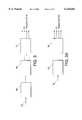
- FIG. 1illustrates a phased array ultrasound imaging system
- FIG. 1Ashows diagrammatically a two-dimensional transducer array and the corresponding electronics integrated into a handle of the imaging system of FIG. 1.
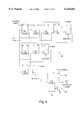
- FIG. 2shows diagrammatically the imaging system with an array of ultrasound transducers connected to several intra-group transmit and receive processors.
- FIGS. 3 and 3Ashow diagrammatically different embodiments of a transmit beamformer channel connected to a transmit intra-group processor shown in FIG. 2.
- FIG. 4shows schematically a digital pulse generator used in the embodiments of FIGS. 3 and 3A.
- FIG. 4Ais a timing diagram showing the reference pulses generated by the digital pulse generator of FIG. 4.
- FIG. 4Bshows diagrammatically a transmit circuit used with the digital pulse generator of FIG. 4.
- FIG. 5shows schematically a programmable delay line made from flip-flop circuits.
- FIG. 5Ashows schematically a dual clock flip-flop used in the programmable delay line of FIG. 5.
- FIG. 6is a block diagram of a summing delay line used in the intra-group receive processors of FIG. 2.
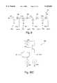
- FIG. 7is a block diagram of programmable delay lines connected to a summing junction used in the intra-group receive processors of FIG. 2.
- FIGS. 8 and 8Ashow diagrammatically tapped delay lines with output taps and input taps, respectively, used as programmable delays.
- FIGS. 9 and 9Ashow diagrammatically sampler lines with output taps and input taps, respectively, used as programmable delays.
- FIGS. 10, 10A and 10Bare schematic diagrams of active filters used as delay elements.
- FIG. 10Cis a schematic diagram of a unity gain buffer used in the embodiments of FIGS. 9, 9A, 10, 10A and 10B.
- FIGS. 11 and 11Aare schematic diagrams of switched capacitor filters used as delay elements.
- FIG. 12shows diagrammatically an analog random access memory element used as a programmable delay element.
- FIG. 12Ashows diagrammatically an implementation of the programmable delay line that uses analog random access memory elements.
- FIG. 13shows diagrammatically a charge coupled device that can be used as a programmable delay element or a programmable delay line.
- FIG. 13Ashows diagrammatically an implementation of the tapped delay line that uses charge coupled devices.
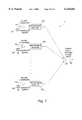
- FIG. 14shows diagrammatically a control circuit for transducer sub-arrays that are connected to an intra-group transmit processor and an intra-group receive processor shown diagrammatically in FIG. 2.
- a phased array ultrasonic imaging system 10includes an array of transducer elements 12 located in a transducer handle 14.
- Transducer handle 14is connected via a transducer cable 16 and a transducer connector 18 to an electronics box 20.
- Electronics box 20is interfaced with a keyboard 22 and provides imaging signals to a display 24.
- Transducer array 12includes several hundred or even several thousand transducer elements arranged as a two-dimensional array, a large one-dimensional array or a 1.5 dimensional array.
- Transducer array 12may have the transducer elements arranged into separate transmit and receive arrays distributed over a selected area (e.g., a circle, an annular pattern). Alternatively, the transducer elements are distributed over a semi-random pattern.
- Transducer handle 14includes transmit pulse generators and the associated high voltage drivers, low noise receive pre-amplifiers, and delay and summing circuits. Importantly, in one preferred embodiment, the elements are integrated within a small volume and placed inside transducer handle 14.
- Transducer cable 16includes signal wires, power supply wires, clock lines, and serial digital data lines including a digital control line and an analog reference current line.
- transducer array 12employs the same transducer elements to emit a transmit beam and detect a receive beam.
- imaging system 10includes a transmit/receive switch (T/R switch not shown in FIG. 1) to switch between a transmit beamformer and a receive beamformer depending on the operating mode.
- the T/R switchincludes N individual switches connected to the N transducer elements. During transmission of ultrasound energy, the switches connect the elements to the transmit beamformer and protect the receive beamformer. After emitting the transmit beam, the T/R switch connects the transducer elements to the receive beamformer.
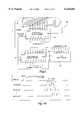
- ultrasound imaging system 10utilizes two-dimensional transducer array 30 having, for example, 3,000 transducer elements to acquire three-dimensional image data of a human organ of interest.
- Imaging system 10uses approximately one half of the transducer elements to transmit ultrasound energy and the other half to receive ultrasound energy.
- the transmit and receive elementsare randomly distributed over array 30. By separating the transmit and receive elements, the system does not need the T/R switch; this reduces the complexity of the system.
- Transducer handle 14includes 120 sub-arrays connected to 30 integrated circuits 34 1 , 34 2 , . . . , 34 20 by 3000 connections 32.
- Transducer cable 16includes 120 output wires (all labeled 36A) providing outputs from the integrated circuits and includes 24 control and power supply wires (all labeled 36B).
- Each integrated circuit 34may include a set of digital pulse generators that generate a 200 nsec wide transmit pulse and high voltage driver circuits that amplify the transmit pulse to 170 volts used to excite the transducer element to emit ultrasound.
- Each integrated circuitmay also include low noise receive preamplifiers, an analog delay circuitry to perform the intra-group receive beamforming, and a digital control circuitry.
- the low noise receive preamplifierspreamplify the transducer signal and provide the preamplified signal to the delay circuitry that performs intra-group receive beamforming by applying selected delay values to the signals.
- the total power dissipated by the transmit and receive intra-group elementsis under 2 Watts.
- FIG. 2is a block diagram of imaging system 10 having transducer array 30 (FIG. 1A) divided into M transmit sub-arrays 30A connected to M intra-group transmit processors and N receive sub-arrays 30B connected to N intra-group receive processors.
- transmit sub-arrays 31 1 , 31 2 , . . . , 31 Mare connected to intra-group transmit processors 38 1 , 38 2 , . . . , 38 M , respectively, which in turn are connected to channels 41 1 , 41 2 , . . . , 41 M of a transmit beamformer 40.
- each intra-group transmit processor 38 iincludes one or more digital pulse generators that provide the transmit pulses and one or more voltage drivers that amplify the transmit pulses to excite the connected transducer elements.
- each intra-group transmit processor 38iincludes a programmable delay line receiving a signal from a conventional transmit beamformer. For example, transmit outputs from ultrasound system HP Sonos 5500 are connected to the intra-group transmit processors instead of the transducer elements.
- each intra-group receive processor 44 imay include a summing delay line, or several programmable delay elements connected to a summing element (a summing junction). Intra-group receive processor 44 i delays the individual transducer signals, adds the delayed signals, and provides the summed signal to one channel 48 i of receive beamformer 46. Alternatively, one intra-group receive processor provides the summed signal to several processing channels 48 i of a parallel receive beamformer. The parallel receive beamformer is constructed to synthesize several receive beams simultaneously. Each intra-group receive processor 44 i may also include several summing delay lines (or groups of programmable delay elements with each group connected to a summing junction) for receiving signals from several points simultaneously.
- a system controller 52includes a microprocessor and an associated memory and is designed to control the operation of imaging system 10.
- System controller 52provides delay commands to the transmit beamformer channels via a bus 53 and also provides delay commands to the intra-group transmit processors via a bus 54.
- the delay datasteers and focuses the generated transmit beams over transmit scan lines of a wedge-shaped transmit pattern, a parallelogram-shaped transmit pattern, or other patterns including three-dimensional transmit patterns.
- a system controller 52also provides delay commands to the channels of the receive beamformer via a bus 55 and delay commands to the intra-group receive processors via a bus 56.
- the applied relative delayscontrol the steering and focussing of the synthesized receive beams.
- Each receive beamformer channel 48 iincludes a variable gain amplifier, which controls gain as a function of received signal depth, and a delay element that delays acoustic data to achieve beam steering and dynamic focusing of the synthesized beam.
- a summing element 50receives the outputs from beamformer channels 48 1 , 48 2 , . . . , 48 N and adds the outputs to provide the resulting beamformer signal to an image generator 58.
- the beamformer signalrepresents a receive ultrasound beam synthesized along a receive scan line.
- Image generator 58constructs an image of a region probed by a multiplicity of round-trip beams synthesized over a sector-shaped pattern, a parallelogram-shaped pattern or other patterns including three-dimensional patterns.
- Both the transmit and receive beamformersmay be analog or digital beamformers as described, for example, in U.S. Pat. Nos. 4,140,022; 5,469,851; or 5,345,426 all of which are incorporated by reference.
- the system controllercontrols the timing of the transducer elements by employing "coarse" delay values in transmit beamformer channels 41 i and "fine" delay values in intra-group transmit processors 38 i .
- a pulse generator 60may provide pulse delay signals to a shift register 66, which provides several delay values to a transmit circuit 70.
- Transmit circuit 70provides high voltage pulses for driving the transmit transducer elements.
- a pulse generator 60may provide pulse delay signals to a delay line 80 connected to a transmit circuit. The delay line provides delay values to the transmit circuit, which provides high voltage pulses for driving the transmit transducer elements.
- digital pulse generator 60includes synchronous counters 62 and 64.
- Synchronous counter 62provides the pulse delay "M”
- synchronous counter 64counts clock cycles for the number "N" of transmit pulses and their width.
- a 7 bit shift register 66provides seven reference pulses with seven delay values that are needed to generate eight different versions of the pulse train each having eight different delay values.
- FIG. 4Ais a timing diagram showing the pulse delay M relative to the transmit trigger, which changes from one sub-array to another depending on the steering angle of the transmit beam. The number of transmit pulses N depends on the transmit mode. In B-mode imaging, a single pulse is transmitted for each transmit event, while in Doppler imaging several pulses are usually transmitted for each transmit event.
- Shift register 66provides the reference pulses to transmit circuit 70, shown in FIG. 4B.
- Transmit circuit 70includes a multiplexer 72 and a high voltage driver with level shifters 74 and transmit driver transistors 76 and 78.
- Multiplexer 72receives eight reference transmit pulses from the shift register 66. Based on a provided delay value, multiplexer 72 selects one of the reference pulses and provides the selected reference pulse to level shifters 74.
- Level shifters 74provide the signal to transmit driver transistors 76 and 78 for driving a transmit element of transducer array 30A (FIG. 2).
- Multiplexer 72replaces seven digital pulse generators having synchronous counters, used in prior art systems.
- the intra-group transmit processors using transmit circuits 70consume less power and occupy a smaller area. Therefore, the intra-group transmit processors or even the entire transmit beamformer can be integrated into transducer handle 14 or connector 18, both of which provide only a limited amount of space for electronic elements and limited ability to dissipate power.
- pulse generator 60is connected to a programmable delay line 80 shown in FIG. 5.
- Programmable delay line 80is integrated for each intra-group transmit processor. In general, a programmable delay line takes less area than the synchronous counters, but does not consume less power.
- programmable delay line 80includes a dual clock flip-flop circuit 90, shown in FIG. 5A. Dual clock flip-flop circuit 90 uses 2 complementary clocks. If the output state is not changed, no current is drawn from Vdd even when the clocks are active. All the power dissipation associated with clocking the D flip-flop occurs in the clock driver circuits, which can be placed outside of transducer handle 14 to prevent overheating. Another use of dual clock flip-flops 90 is within the synchronous counters to reduce their power dissipation.
- FIGS. 6 and 7show different embodiments of intra-group receive processors 44 1 , 44 2 , . . . , 44 N (shown in FIG. 2).
- a summing delay line 100receives signals from receive transducers 28 1 , 28 2 , . . . , 28 R , which form one sub-array 42, of transducer array 30B.
- Summing delay line 100includes a variable cross point switch 104 connected to delay elements 108 1 , 108 2 , . . . , 108 x+1 and summing elements (summing junctions) 110 1 , 110 2 , . . . , 110 x .
- Each receive transducer 28 iprovides a signal to a preamplifier / conditioner 102 i , and the preamplified signal is then steered by variable cross point switch 104 to one selected tap 106 i or simultaneously to several selected taps 106 i .
- summing delay line 100enables interpolation of the transducer signals between taps 106 i to achieve a fine control over the delay applied to the preamplified transducer signals. That is, the transducer signal can be weighted by two different gains and sent into two taps 106 i ; this achieves a delay smaller than the delay provided by a single delay element.
- This type of interpolationcan use linear weights (i.e., the amplitude of the weighted signals add up to 1), or non-linear weights that give the same signal amplitude as would be obtained using a single delay value.
- Summing delay line 100can also provide delay values larger than the delay values provided by analog delay elements 108 1 , 108 2 , . . . , 108 x+1 by programming a delay value that is an integer number of wavelengths from the desired delay value.
- analog phase shiftersare included to add a phase shift to the signal to provide the needed difference in delay.
- Delay element 108 imay be a sample-and-hold element, an active filter element, or a switched capacitor filter, all of which are discussed below.
- Pre-amplifier and conditioner 102may include a T/R switch, a pre-amplifier or a variable gain amplifier. Output 112 from the last delay element is coupled to one processing channel 48 i of receive beamformer 46.
- an intra-group analog receive processor 115includes a set of programmable delay lines 118 1 , 118 2 and 118 R connected to a summing element 120. From an output 122, summing element 120 provides the delayed and summed signals to one processing channel 48 i of receive beamformer 46.
- Each programmable delay line 118 imay be implemented as an analog delay line or a digital delay line.
- Each analog delay line 118 ican include a charge coupled device, an analog RAM, a sample and hold circuit, an active filter, an L-C filters, or a switched capacitor filter as is described in connection with FIGS. 8 through 13.
- the programmable delay linemay include a delay line 125 with output taps, or a delay line 145 with input taps, respectively.
- Delay line 125includes three fixed delay elements 130, 133, and 136 connected by eight switches (128A, 128B, 131A, 131B, 134A, 134B, 137A and 137B) to two fix gain attenuators 138 and 140.
- Fixed gain attenuators 138 and 140are connected to a summing junction 142.
- Delay elements 130, 133 and 136are connected to a power supply Vdd by switches 129, 132 and 135, respectively.
- Switches 129, 132 and 135are used to turn off the Vdd power supply from the unused delays to save power.
- Fix gain attenuators 138 and 140 in combination with output switches 128A, 128B, 131A, 131B, 134A, 134B, 137A and 137Ballow interpolation of delay values and give finer delay control than the delay provided by a single delay element 130, 133 or 136.
- Each delay elementcan again be a filter element or a sample-and-hold delay element.
- delay line 125includes fix gain attenuator 138 providing 0.7 gain and fix gain attenuator 140 providing 0.3 gain.
- Each delay element 130, 133 or 136provides a 90 degree phase shift.
- An ON/OFF combination of switches 128A, 128B, 131A, 131B, 134A, 134B, 137A and 137Bwill provide a signal with a desired delay.
- Delay line 145includes three fixed delay elements 150, 153 and 156 connected by eight input switches (148A, 148B, 151A, 151B, 154A, 154B, 157A and 157B) to two fix gain attenuators 158 and 160.
- Delay elements 150, 153 and 156are connected to a power supply Vdd by switches 149, 152 and 155, respectively. Switches 149, 152 and 155 are used to turn off the Vdd power supply from the unused delays to save power.
- Fixed gain attenuators 158 and 160 in combination with input switches 148A, 148B, 151A, 151B, 154A, 154B, 157A and 157Ballow interpolation of delay values and give finer delay control than the delay provided by a single delay element 150, 153 or 156.
- Each delay elementcan again be a filter element or a sample-and-hold delay element.
- FIGS. 9 and 9Ashow diagrammatically sampler chains with output taps and input taps, respectively, used in the intra-group receive processors of FIG. 2.
- Sampler line 170shown in FIG. 9, includes a series of sample-and-hold elements 174 0 , 174 1 , . . . , 174 3 and a series of outputs 172 0 , 172 1 , . . . , 172 3 controlled by a digital clock. Between two samplers there is a unity gain buffer 186 shown in FIG. 10C.
- the sample clock frequencyis at least twice the highest signal frequency component in order to meet the Nyquist criteria. To support bandwidths up to 100%, the clock frequency is 4 times the ultrasound RF center frequency.
- sampler line 170uses a 10 MHz clock frequency and has 4 stages to achieve a 200 nsec delay with 50 nsec taps.
- Sampler line 175, shown in FIG. 9A,includes a series of samplers 174 0 , 174 1 , . . . , 174 3 and a series of inputs 176 0 , 176 1 , . . . , 176 3 controlled by a digital clock.
- a unity gain buffer 186is located between two sample-and-hold elements. Signals provided by inputs 176 1 , 176 2 , and 176 3 are summed into the line by summing elements 178 1 , 178 2 , and 178 3 .
- the sample clock frequencyis at least twice the highest signal frequency component in order to meet the Nyquist criteria.
- Sampler lines 170 or 175are used as delay line 118 i of FIG. 7.
- sample-and-hold elements 174 i together with summing elements 178 iare used as summing delay line 100 shown in FIG. 6.
- the delay elementsare Sallen and Key implementations of 2-pole active filters 180, 182 and 188.
- Two-pole active filter 180may be used in summing delay line 100 or delay lines 125 or 145. Active filter 180 produces a 50 nsec delay at a 5 MHz bandwidth.
- Active filters 182 and 188provide programmable delays and may replace delay lines 118 1 , 118 2 and 118 R in intra-group receive processor 115 (FIG. 7).
- Active filter 182provides programmable delay by using a set of resistors 184a through 184f connected to a unity gain buffer 186 by switches 183a through 183f.
- active filter 188provides programmable delay values by using a set of capacitors 190 connected to a unity gain buffer 186 by a set of switches 192.
- the filter's impedancechanges that in turn changes the phase response (i.e., the delay).
- There are several other filter topologies that can be used as delay elementsSee, for example, Y. P. Tsvidis and J. O. Voorman "Integrated continuous-time filters" IEEE Press, 1993).
- the delay elementis a switched capacitor filter 200.
- Switched-capacitor filter 200includes capacitors C 1 , C 2 , and C 3 , switches S 1 and S 2 , and an op-amp A arranged as an integrator.
- Single pole double throw switches S 1 and S 2can operate at more than twice the ultrasound center frequency, for example, 10 MHz.
- switches S 1 and S 2may be implemented as MOSFETs S A , S B , S C , and S D .
- the switching signals CLK and CLKNare derived from a non-overlapping two phase clock of a selected frequency.
- the delay valuecan be changed either by using different capacitor values, or by using different clock frequencies. Since these delay elements do not use resistors, their power consumption is relatively low.
- There are several other filter topologies that can be usedsee, for example, M. E. Van Valkenburg "Analog Filter Design" CBS college publishing 1982).
- an analog random access memory (RAM) device 210is used as a programmable delay element.
- RAM device 210includes a group of M storage capacitors 214 1 , 214 2 , . . . , 214 M for storing M input sample signals using decoders 216 and 218 connected to input switches 215 1 , 215 2 , . . . , 215 M and output switches 217 1 , 217 2 , . . . , 217 M , respectively.
- An input buffer 212receives a transducer signal that is then sent by input switch 215 i controlled by decoder 216 to storage capacitor 214i.
- Decoder 218 coupled to output switch 217 isamples the individual capacitor charges at delay times determined by the difference in timing between an input counter 220 and an output counter 222. Thus, the transducer signals are delayed by selected delay times as they are transferred from input buffer 212 to an output buffer 224.
- the analog RAM devicemay use only a single capacitor for delaying the ultrasound transducer signal in order to reduce the noise and signal distortion.
- FIG. 12Ashows diagrammatically a programmable delay line 225, which includes analog RAMs 210 0 , 210 1 , 210 2 and 210 3 , unity gain buffers 186 0 , 186 1 , 186 2 and 186 3 , and a set of output taps 227 0 , 227 1 , 227 2 and 227 3 .
- each analog RAMincludes two storage capacitors 214 i , shown in FIG. 12.
- Delay line 225is controlled by a complementary clock signals CLK and CLKN, wherein the CLK frequency is two times the ultrasound RF frequency.
- Output taps 227are located every 1/4 of the RF period.
- the programmable delay elementis implemented as a charge coupled device (CCD) 230, which includes a chain of capacitors and field effect transistors connected in series.
- the charge coupled devicemay be used as a delay element or a delay line.
- CCD line 230includes an N:1 multiplexor 232, which provides clock signals to a 10 stage CCD 234.
- CCD 234receives the transducer signal at an input 236 and passes the corresponding charge from one capacitor to another each clock period until it reaches an output 238.
- the total delay required to pass through the CCDis determined by the number of stages and the clock frequency.
- the delay timeis controlled by changing the clock frequency, as shown in Table 1.
- Multiplexor 232receives a set of frequencies and provides the appropriate clock frequency (233) to CCD 234 based on a delay value received by a control input 231.
- the deviceincludes several filters that eliminate clock feed-through across a range of possible clock frequencies.
- FIG. 13Ashows diagrammatically an implementation of the tapped delay line that uses charge coupled devices.
- a tapped delay line 240includes a row of closely spaced metallic electrodes 242 1 , 242 2 , . . . , 243 1 , 243 2 , . . . , and 244 1 , 244 2 , . . . , deposited on an SiO 2 insulator and several N + regions 246 1 , 246 2 , . . . , and 248 1 , 248 2 , . . . located in a P-type substrate.
- N + regions 246 1 , 246 2 , . . .are connected to input taps IN 1 , IN 2 , . .
- Electrodes 242 1 , 242 2 , . . . , 243 1 , 243 2 , . . . , and 244 1 , 244 2 , . . .are connected to a three-phase clock CLK 1 , CLK 2 and CLK 3 arranged to transfer longitudinally the charge accumulated under the electrodes.
- Delay line 240receives the ultrasound transducer signal at input taps IN 1 , IN 2 , .
- the delay timedepends on the clock frequency and the location of the input and output taps.
- the description of standard CCDsis provided in "Charge Coupled Devices and Their Application", Beynon et al., McGraw Hill, 1980.
- the imaging systemincludes system controller 52 with a digital control circuit for providing the delay values to the intra-group transmit and receive processors and the transmit and receive beamformers, as shown diagrammatically by data buses 53 through 56.
- the beamformer channelsreceive "coarse" delay values, and the intra-group processors receive "fine” delay values.
- the intra-group receive processorscannot be loaded with the delay data while receiving the transducer signals, which are quite weak, because the digital noise, arising from the loading of the delay data, would swamp the weak signals. Therefore, the delay data for each of the 3000 transducer elements must be loaded prior to transmitting each acoustic line.
- Each elementneeds about 4 bits of delay data; this corresponds to 12,000 bits of control information, which must be loaded prior to each transmit event.
- the control informationhas to be loaded in about 10 microseconds; this requires about 75 MHz clock to load 12,000 bits over 16 serial lines in 10 microseconds. While this high rate is possible, there are several ways to reduce this loading rate depending on the mode of operation.
- the digital control circuitprovides the same delay profile to all intra-group receive processors.
- the intra-group processorscan have the delay data loaded in parallel by providing one delay profile to all intra-group processors.
- the control circuitryloads the delay data to all intra-group processors over a serial line. For example, a processor with 25 elements is loaded over a single serial line clocked at 10 MHz in about 10 microseconds.
- the intra-group processorssteer the acoustic beams by applying the same steering angle to all processors.
- the intra-group processors loaded with the identical delay profilecannot, however, focus the acoustic beam. Thus, in this embodiment, an acoustic lens may need to be used for focussing.
- the intra-group processorsare used for both steering and focussing.
- the control circuitryprovides the steering angle delay data to each intra-group processor.
- Each processorreceives delay data that steers the receive beam at a slightly different angle to achieve focussing.
- the delay data for each elementis calculated within each intra-group processor by using several adders, as shown in FIG. 14.
- FIG. 14shows diagrammatically a control circuit 250 used for a 5 ⁇ 5 cell sub-array.
- This sub-arrayincludes 12 transmit cells connected to an intra-group transmit processor and 13 receive cells connected to an intra-group receive processor.
- the control circuitincludes a shift register 252 for holding an incremental x value, a shift register 254 for holding an incremental y value, and an initial value register 256.
- Incremental x and y valuesare directly related to the steering angles in the two-dimensional image plane.
- Each transmit cell 260(labeled with an X) includes a transmit transducer and the transmit circuitry (e.g., a high voltage driver).
- Each receive cell 264(labeled with an R) includes a receive transducer, a receive preamplifier, and may include the receive circuitry depending on the type of intra-group processor used.
- the summing elementsare preferably asynchronous with no lookahead carry circuitry in order to save power and circuit area.
- a serial busprovides an initial delay value to initial value register 256 and the x and y delay increments to shift registers 252 and 254, respectively.
- Summing elements 268provide the appropriate delay values for the transducer elements by adding the initial delay value (or the neighboring delay value) and the x and y delay increments. The delays within the group are approximately linear with respect to the cell position so that the summing element associated with each cell can calculate it's delay by a simple offset from it's neighbor's delay.
- Transmit cells 260receive the delay values calculated by summing elements 238 via connections 261.
- Receive cells 264receive the delay values calculated by summing elements 268 via connections 265. The delay data is used for steering and focussing.
- transmit cells 260may also include shift register 66. Transmit cell 260 i receives a reference pulse via a connection 262 i , and the shift register provides one of eight delay values to the level shifters.
- shift register 66is located outside of transmit cell 260 i and provides to the cell reference pulses via eight connection lines 262 (only one connection line 262 i is shown for simplicity).
- Digital pulse generator 60 together with shift register 66generate eight reference transmit pulses of N cycles long and delayed from a transmit trigger pulse by M transmit clock cycles plus eight different additional delays.
- transmit cell 262 iincludes delay line 80. Transmit cell 262 i receives a reference pulse from digital pulse generator 60 via connection 262 i and delay line 80 provides the signal to level shifters 74.
- receive cells 264After detecting the ultrasound echos, receive cells 264 provide pre-amplified acoustic data to the intra-group receive processor. Also referring to FIG. 6, in one embodiment, if the intra-group processor uses summing delay line 100 each receive cell 264, provides the pre-amplified acoustic data via a single connection 266 i to one variable gain cross-point switch 104 located outside of the receive cells. That is, there is only one variable gain cross-point switch receiving the acoustic data from all 13 receive cells 264. In another embodiment using summing delay line 100, each receive cell 264 i includes one variable gain cross-point switch with a smaller number of switches than when only one cross-point switch is used for all receive cells 264.
- Each receive cell 264 ihas several connections 266 providing the acoustic data to summing delay line 100 (FIG. 6). Now referring to FIG. 7, in another embodiment, each receive cell 264 i provides the pre-amplified acoustic data via a single connection 266, to one programmable delay element 118 i .
- the intra-group receive processorreceives the transducer signal from 13 receive cells 264 and provides the summed signal (122) to one channel of the receive beamformer. Depending on the delay values applied by delay elements 118 i , echoes scattered from a selected point are summed.
Landscapes
- Engineering & Computer Science (AREA)
- Physics & Mathematics (AREA)
- Radar, Positioning & Navigation (AREA)
- Remote Sensing (AREA)
- Computer Networks & Wireless Communication (AREA)
- General Physics & Mathematics (AREA)
- Health & Medical Sciences (AREA)
- Acoustics & Sound (AREA)
- Life Sciences & Earth Sciences (AREA)
- Nuclear Medicine, Radiotherapy & Molecular Imaging (AREA)
- Molecular Biology (AREA)
- Biophysics (AREA)
- Veterinary Medicine (AREA)
- Pathology (AREA)
- Radiology & Medical Imaging (AREA)
- Biomedical Technology (AREA)
- Heart & Thoracic Surgery (AREA)
- Medical Informatics (AREA)
- Gynecology & Obstetrics (AREA)
- Surgery (AREA)
- Animal Behavior & Ethology (AREA)
- General Health & Medical Sciences (AREA)
- Public Health (AREA)
- Multimedia (AREA)
- Ultra Sonic Daignosis Equipment (AREA)
- Measurement Of Velocity Or Position Using Acoustic Or Ultrasonic Waves (AREA)
Abstract
Description
TABLE 1 __________________________________________________________________________Frequency 10 10.56 11.11 11.76 12.25 13.33 14.29 15.35 16.67 18.18 [MHz] Delay 1000 950 900 850 800 750 700 650 600 550 [nsec] __________________________________________________________________________Frequency 20.20 22.22 25.00 28.57 33.33 40.00 50.00 [MHz]Delay 500 450 400 350 300 250 200 [nsec] __________________________________________________________________________
Claims (38)
Priority Applications (1)
| Application Number | Priority Date | Filing Date | Title |
|---|---|---|---|
| US09/398,353US6126602A (en) | 1998-05-28 | 1999-09-17 | Phased array acoustic systems with intra-group processors |
Applications Claiming Priority (2)
| Application Number | Priority Date | Filing Date | Title |
|---|---|---|---|
| US09/085,718US5997479A (en) | 1998-05-28 | 1998-05-28 | Phased array acoustic systems with intra-group processors |
| US09/398,353US6126602A (en) | 1998-05-28 | 1999-09-17 | Phased array acoustic systems with intra-group processors |
Related Parent Applications (1)
| Application Number | Title | Priority Date | Filing Date |
|---|---|---|---|
| US09/085,718ContinuationUS5997479A (en) | 1998-05-28 | 1998-05-28 | Phased array acoustic systems with intra-group processors |
Publications (1)
| Publication Number | Publication Date |
|---|---|
| US6126602Atrue US6126602A (en) | 2000-10-03 |
Family
ID=22193501
Family Applications (2)
| Application Number | Title | Priority Date | Filing Date |
|---|---|---|---|
| US09/085,718Expired - LifetimeUS5997479A (en) | 1998-05-28 | 1998-05-28 | Phased array acoustic systems with intra-group processors |
| US09/398,353Expired - LifetimeUS6126602A (en) | 1998-05-28 | 1999-09-17 | Phased array acoustic systems with intra-group processors |
Family Applications Before (1)
| Application Number | Title | Priority Date | Filing Date |
|---|---|---|---|
| US09/085,718Expired - LifetimeUS5997479A (en) | 1998-05-28 | 1998-05-28 | Phased array acoustic systems with intra-group processors |
Country Status (2)
| Country | Link |
|---|---|
| US (2) | US5997479A (en) |
| JP (1) | JP4579357B2 (en) |
Cited By (86)
| Publication number | Priority date | Publication date | Assignee | Title |
|---|---|---|---|---|
| US6500120B1 (en) | 2001-07-31 | 2002-12-31 | Koninklijke Philips Electronics N.V. | Beamforming system using analog random access memory |
| WO2003071306A1 (en)* | 2002-02-20 | 2003-08-28 | Koninklijke Philips Electronics N.V. | Portable 3d ultrasound system |
| US6676602B1 (en)* | 2002-07-25 | 2004-01-13 | Siemens Medical Solutions Usa, Inc. | Two dimensional array switching for beamforming in a volume |
| US20040049110A1 (en)* | 2002-09-09 | 2004-03-11 | Acuson, A Siemens Company | Multiple pattern transducer array and method of use |
| US6705995B1 (en) | 2002-10-04 | 2004-03-16 | Koninklijke Philips Electronics N.V. | Method and apparatus for 1D array ultrasound probe |
| US20040062370A1 (en)* | 1999-01-29 | 2004-04-01 | Microsoft Corporation | Interactive billing control system |
| JP2004130137A (en)* | 2002-10-11 | 2004-04-30 | Koninkl Philips Electronics Nv | Rfi-protected ultrasonic search unit |
| US20040092816A1 (en)* | 2002-11-08 | 2004-05-13 | Koninklijke Philips Electronics N.V. | Artifact elimination in time-gated anatomical imaging |
| WO2004064619A2 (en) | 2003-01-14 | 2004-08-05 | University Of Virginia Patent Foundation | Ultrasound imaging beam-former apparatus and method |
| US6783497B2 (en) | 2002-05-23 | 2004-08-31 | Volumetrics Medical Imaging, Inc. | Two-dimensional ultrasonic array with asymmetric apertures |
| US20040215077A1 (en)* | 2002-11-08 | 2004-10-28 | Witt Jerome F. | Color ensemble interleave with artifact elimination in time-gated anatomical imaging |
| US20050020918A1 (en)* | 2000-02-28 | 2005-01-27 | Wilk Ultrasound Of Canada, Inc. | Ultrasonic medical device and associated method |
| US20050096545A1 (en)* | 2003-10-30 | 2005-05-05 | Haider Bruno H. | Methods and apparatus for transducer probe |
| US20050101867A1 (en)* | 2003-10-28 | 2005-05-12 | Johnson Jeremy A. | Apparatus and method for phased subarray imaging |
| US20050113699A1 (en)* | 2003-11-21 | 2005-05-26 | Haugen Geir U. | Ultrasound probe sub-aperture processing |
| US20050113694A1 (en)* | 2003-11-21 | 2005-05-26 | Haugen Geir U. | Ultrasound probe distributed beamformer |
| US20050119576A1 (en)* | 2003-11-21 | 2005-06-02 | Koninklijke Philips Electronics N.V. | Three dimensional ultrasonic imaging using mechanical probes with beam scanning reversal |
| US20050119575A1 (en)* | 2003-02-14 | 2005-06-02 | Igal Ladabaum | Microfabricated ultrasonic transducer array for 3-D imaging and method of operating the same |
| US20050124887A1 (en)* | 2003-11-21 | 2005-06-09 | Koninklijke Philips Electronics N.V. | Three dimensional scan conversion of data from mechanically scanned array probes |
| US20050124882A1 (en)* | 2003-02-14 | 2005-06-09 | Igal Ladabaum | System and method of operating microfabricated ultrasonic transducers for harmonic imaging |
| US20050148873A1 (en)* | 2003-12-19 | 2005-07-07 | Siemens Medical Solutions Usa, Inc. | Ultrasound adaptor methods and systems for transducer and system separation |
| US20050203404A1 (en)* | 2004-02-26 | 2005-09-15 | Siemens Medical Solutions Usa, Inc. | Steered continuous wave doppler methods and systems for two-dimensional ultrasound transducer arrays |
| US20050203391A1 (en)* | 2004-02-26 | 2005-09-15 | Siemens Medical Solutions Usa, Inc. | Element mapping and transmitter for continuous wave ultrasound imaging |
| US20050228277A1 (en)* | 2004-04-05 | 2005-10-13 | Siemens Medical Solutions Usa, Inc. | System and method for 2D partial beamforming arrays with configurable sub-array elements |
| US20050228287A1 (en)* | 2004-04-08 | 2005-10-13 | Sonosite, Inc. | Systems and methods providing ASICs for use in multiple applications |
| US20060035481A1 (en)* | 2004-08-13 | 2006-02-16 | Petersen David A | Interconnection from multidimensional transducer arrays to electronics |
| US20060173342A1 (en)* | 2003-02-14 | 2006-08-03 | Satchi Panda | Method and apparatus for improving the performance of capacitive acoustic transducers using bias polarity control and multiple firings |
| US20060173326A1 (en)* | 2003-06-10 | 2006-08-03 | Koninklijke Philips Electronics N.V. | User interface for a three-dimensional colour ultrasound imaging system |
| US20070032724A1 (en)* | 2003-06-03 | 2007-02-08 | Koninklijke Philips Electronics N.V. | Synchronizing a swiveling three-dimensional ultrasound display with an oscillating object |
| EP1757230A1 (en)* | 2001-07-31 | 2007-02-28 | Koninklijke Philips Electronics N.V. | Transesophageal and transnasal, transesophageal ultrasound imaging systems . |
| US20070167752A1 (en)* | 2005-12-07 | 2007-07-19 | Siemens Medical Solutions Usa, Inc. | Ultrasound imaging transducer array for synthetic aperture |
| US20070183429A1 (en)* | 2003-06-02 | 2007-08-09 | Yang Woo Y | Aalo cell format of an atm protocol for communicating voice traffic in a cdma system |
| US20070208254A1 (en)* | 2003-10-28 | 2007-09-06 | Johnson Jeremy A | Apparatus and method for phased subarray imaging |
| US20070225604A1 (en)* | 2004-09-29 | 2007-09-27 | Matsushita Electric Industrial Co., Ltd. | Ultrasonic Diagnostic System |
| US20070242567A1 (en)* | 2005-12-07 | 2007-10-18 | Daft Christopher M | Multi-dimensional CMUT array with integrated beamformation |
| US20080125659A1 (en)* | 2006-11-28 | 2008-05-29 | Siemens Medical Solutions Usa, Inc. | Helical acoustic array for medical ultrasound |
| US20080146938A1 (en)* | 2006-12-15 | 2008-06-19 | General Electric Company | Method and system for sub-aperture processing |
| US20080294045A1 (en)* | 2003-11-21 | 2008-11-27 | Becky Ellington | Three Dimensional Ultrasonic Imaging Using Mechanical Probes with Beam Scanning Reversal |
| US20080314530A1 (en)* | 2007-06-22 | 2008-12-25 | Li-Ming Cheng | Window coverings |
| US20090005684A1 (en)* | 2007-06-28 | 2009-01-01 | General Electric Company | Transmit beamforming in 3-dimensional ultrasound |
| US20090007414A1 (en)* | 2005-06-28 | 2009-01-08 | Phelps Robert N | Scalable ultrasound system and methods |
| US20090015101A1 (en)* | 2007-07-10 | 2009-01-15 | Siemens Medical Solutions Usa, Inc. | Embedded circuits on an ultrasound transducer and method of manufacture |
| US7508113B2 (en) | 2004-05-18 | 2009-03-24 | Siemens Medical Solutions Usa, Inc. | Apparatus for two-dimensional transducers used in three-dimensional ultrasonic imaging |
| US20090093720A1 (en)* | 2004-02-26 | 2009-04-09 | Petersen David A | Receive circuit for minimizing channels in ultrasound imaging |
| US20090315747A1 (en)* | 2008-06-24 | 2009-12-24 | Nee Chi-Ping | Method and Apparatus for Delay and Combining Circuitry |
| US20100016725A1 (en)* | 2006-12-20 | 2010-01-21 | Koninklijke Philips Electronics N.V. | Multi-beam transmit isolation |
| WO2010055428A1 (en)* | 2008-11-11 | 2010-05-20 | Koninklijke Philips Electronics, N.V. | Configurable microbeamformer circuit for an ultrasonic diagnostic imaging system |
| WO2010076722A1 (en) | 2008-12-29 | 2010-07-08 | Koninklijke Philips Electronics N.V. | Ultrasound imaging system with remote control and method of operation thereof |
| US20100280387A1 (en)* | 2009-04-29 | 2010-11-04 | Rea Richard Schmid | Active Delay Line for Continuous Wave Ultrasound System |
| US20110015525A1 (en)* | 2008-03-07 | 2011-01-20 | Panasonic Corporation | Ultrasonograph |
| US20110021921A1 (en)* | 2009-07-21 | 2011-01-27 | Aloka Co., Ltd. | Ultrasound diagnostic apparatus |
| US20110028846A1 (en)* | 2009-07-28 | 2011-02-03 | Aloka Co., Ltd. | Ultrasonic diagnostic apparatus |
| US20110176390A1 (en)* | 2010-01-15 | 2011-07-21 | Jimes Lei | Low pin count high voltage ultrasound transmitter and method therefor |
| US7998072B2 (en) | 2003-12-19 | 2011-08-16 | Siemens Medical Solutions Usa, Inc. | Probe based digitizing or compression system and method for medical ultrasound |
| US8206305B2 (en) | 2006-11-28 | 2012-06-26 | Siemens Medical Solutions Usa, Inc. | Multi-twisted acoustic array for medical ultrasound |
| WO2012101511A3 (en)* | 2011-01-28 | 2012-11-01 | Cardio Art Technologies Ltd. | System, method and device for automatic and autonomous determination of hemodynamic and cardiac parameters using ultrasound |
| WO2013042029A1 (en)* | 2011-09-22 | 2013-03-28 | Koninklijke Philips Electronics N.V. | Excitation schemes for low-cost transducer arrays |
| WO2014001962A1 (en) | 2012-06-28 | 2014-01-03 | Koninklijke Philips N.V. | Two dimensional ultrasound transducer arrays operable with different ultrasound systems |
| WO2014087306A2 (en) | 2012-12-03 | 2014-06-12 | Koninklijke Philips N.V. | Ultrasound transducer probe with microbeamformer for multiline imaging |
| US8764664B2 (en) | 2005-11-28 | 2014-07-01 | Vizyontech Imaging, Inc. | Methods and apparatus for conformable medical data acquisition pad and configurable imaging system |
| US8834375B2 (en) | 2011-01-27 | 2014-09-16 | Kabushiki Kaisha Toshiba | Ultrasound probe and ultrasound diagnosis apparatus |
| EP2860547A1 (en)* | 2013-10-08 | 2015-04-15 | Samsung Electronics Co., Ltd | Apparatus and method for beamforming |
| WO2015161157A1 (en)* | 2014-04-18 | 2015-10-22 | Butterfly Network, Inc. | Architecture of single substrate ultrasonic imaging devices, related apparatuses, and methods |
| US9244160B2 (en) | 2003-01-14 | 2016-01-26 | University Of Virginia Patent Foundation | Ultrasonic transducer drive |
| US9254118B2 (en) | 2013-03-15 | 2016-02-09 | Analogic Corporation | Floating transducer drive, system employing the same and method of operating |
| WO2016024147A1 (en)* | 2014-08-13 | 2016-02-18 | B-K Medical Aps | Ultrasound signal analog beamformer / beamforming |
| WO2016077822A1 (en) | 2014-11-14 | 2016-05-19 | Ursus Medical, Llc | Ultrasound beamforming system and method based on aram array |
| US20170074837A1 (en)* | 2015-09-16 | 2017-03-16 | Samsung Medison Co., Ltd. | Ultrasonic probe, ultrasonic imaging apparatus including the same, and method for controlling the ultrasonic imaging apparatus |
| US9739875B2 (en) | 2013-02-12 | 2017-08-22 | Urs-Us Medical Technology Inc. | Analog store digital read ultrasound beamforming system and method |
| WO2017168279A1 (en) | 2016-03-30 | 2017-10-05 | Koninklijke Philips N.V. | Two dimensional ultrasonic array transducer with one dimensional subpatches |
| WO2017167742A1 (en) | 2016-03-30 | 2017-10-05 | Koninklijke Philips N.V. | Two dimensional ultrasonic array transducer with one dimensional patches |
| WO2017207815A1 (en) | 2016-06-02 | 2017-12-07 | Koninklijke Philips N.V. | Ultrasound systems with time compression and time multiplexing of received ultrasound signals |
| WO2018041644A1 (en) | 2016-09-02 | 2018-03-08 | Koninklijke Philips N.V. | Ultrasound probe with digital microbeamformer using fir filters with no multipliers |
| WO2018041636A1 (en) | 2016-09-02 | 2018-03-08 | Koninklijke Philips N.V. | Ultrasound probe with multiline digital microbeamformer |
| WO2018041635A1 (en) | 2016-09-02 | 2018-03-08 | Koninklijke Philips N.V. | Ultrasound probe with digital microbeamformer having integrated circuits fabricated with different manufacturing processes |
| WO2018041987A1 (en) | 2016-09-02 | 2018-03-08 | Koninklijke Philips N.V. | Ultrasound probe with low frequency, low voltage digital microbeamformer |
| US10226229B2 (en) | 2011-08-18 | 2019-03-12 | Toshiba Medical Systems Corporation | Ultrasound diagnosis apparatus |
| US10365367B2 (en) | 2010-12-28 | 2019-07-30 | General Electric Company | 4D data ultrasound imaging system and corresponding control process |
| US10945706B2 (en) | 2017-05-05 | 2021-03-16 | Biim Ultrasound As | Hand held ultrasound probe |
| US10955537B2 (en)* | 2018-08-17 | 2021-03-23 | Acoustiic Inc. | High speed distribution of data for control of ultrasound devices |
| US11249188B2 (en)* | 2015-12-30 | 2022-02-15 | Koninklijke Philips N.V. | System and method for dynamic filtering |
| US20220125413A1 (en)* | 2020-10-22 | 2022-04-28 | Fujifilm Healthcare Corporation | Ultrasound probe |
| US11317893B2 (en) | 2016-09-02 | 2022-05-03 | Koninklijke Philips N.V. | 2D array ultrasound probe with 3 watt digital microbeamformer |
| EP4007969A4 (en)* | 2019-09-24 | 2022-10-12 | Fingerprint Cards Anacatum IP AB | BIOMETRIC ULTRASOUND IMAGING SYSTEM AND METHOD FOR CONTROLLING THE BIOMETRIC ULTRASOUND IMAGING SYSTEM |
| US20230228858A1 (en)* | 2022-01-20 | 2023-07-20 | Fujifilm Healthcare Corporation | Ultrasound imaging apparatus and signal processing method |
| US11771403B2 (en) | 2016-09-02 | 2023-10-03 | Koninklijke Philips N.V. | Ultrasound probe with thirty-two channel digital microbeamformer |
Families Citing this family (344)
| Publication number | Priority date | Publication date | Assignee | Title |
|---|---|---|---|---|
| US6380766B2 (en)* | 1999-03-19 | 2002-04-30 | Bernard J Savord | Integrated circuitry for use with transducer elements in an imaging system |
| US6371918B1 (en)* | 1999-05-05 | 2002-04-16 | Sonosite Inc. | Transducer connector |
| US6293912B1 (en)* | 1999-06-10 | 2001-09-25 | B-K Medical A/S | Ultrasound scanner with beam former |
| KR100355719B1 (en)* | 2000-06-10 | 2002-10-11 | 주식회사 메디슨 | Ultrasound receive beamforming apparatus using multi-tier delay devices |
| US7037264B2 (en)* | 2000-08-17 | 2006-05-02 | Koninklijke Philips Electronics N.V. | Ultrasonic diagnostic imaging with steered image plane |
| US6709394B2 (en) | 2000-08-17 | 2004-03-23 | Koninklijke Philips Electronics N.V. | Biplane ultrasonic imaging |
| DE60115837T2 (en) | 2000-08-24 | 2006-08-17 | Koninklijke Philips Electronics N.V. | TRANSDUCER ARRANGEMENT OF AN ULTRASOUND DIAGNOSTIC PICTURE SYSTEM WITH MULTIPLE LINES |
| EP1216473B1 (en)* | 2000-08-24 | 2007-03-07 | Koninklijke Philips Electronics N.V. | Ultrasonic diagnostic imaging system with dynamic microbeamforming |
| US6468216B1 (en)* | 2000-08-24 | 2002-10-22 | Kininklijke Philips Electronics N.V. | Ultrasonic diagnostic imaging of the coronary arteries |
| US6440073B1 (en) | 2000-09-13 | 2002-08-27 | Koninklijke Philips Electronics N.V. | Ultrasonic diagnostic imaging system with automatic restart and response |
| US6450958B1 (en) | 2000-09-13 | 2002-09-17 | Koninklikje Philips Electronics N.V. | Portable ultrasound system with efficient shutdown and startup |
| US6527719B1 (en) | 2000-09-13 | 2003-03-04 | Koninklijke Philips Electronics N.V. | Ultrasonic diagnostic imaging system with reduced power consumption and heat generation |
| US6527721B1 (en) | 2000-09-13 | 2003-03-04 | Koninklijke Philips Electronics, N.V. | Portable ultrasound system with battery backup for efficient shutdown and restart |
| US6602194B2 (en) | 2000-09-15 | 2003-08-05 | Koninklijke Philips Electronics N.V. | Dual beamformer ultrasound system for 2D and 3D imaging |
| US6582367B1 (en) | 2000-09-15 | 2003-06-24 | Koninklijke Philips Electronics N.V. | 2D ultrasonic transducer array for two dimensional and three dimensional imaging |
| US6491634B1 (en) | 2000-10-13 | 2002-12-10 | Koninklijke Philips Electronics N.V. | Sub-beamforming apparatus and method for a portable ultrasound imaging system |
| US6491630B1 (en) | 2000-11-09 | 2002-12-10 | Koninklijke Philips Electronics N.V. | Ultrasound imaging device having a soft keyboard for entering data |
| US6471649B1 (en) | 2000-11-09 | 2002-10-29 | Koninklijke Philips Electronics N.V. | Method and apparatus for storing image information in an ultrasound device |
| US6440076B1 (en) | 2000-11-09 | 2002-08-27 | Koninklijke Philips Electronics N.V. | Ultrasound transducer connector assembly |
| US6540682B1 (en)* | 2000-11-09 | 2003-04-01 | Koninklijke Philips Electronics N.V. | Portable, configurable and scalable ultrasound imaging system |
| US6540685B1 (en) | 2000-11-09 | 2003-04-01 | Koninklijke Philips Electronics N.V. | Ultrasound diagnostic device |
| US6436040B1 (en) | 2000-11-09 | 2002-08-20 | Koninklijke Philips Electronics N.V. | Intuitive user interface and control circuitry including linear distance measurement and user localization in a portable ultrasound diagnostic device |
| US6542846B1 (en) | 2000-11-09 | 2003-04-01 | Koninklijke Philips Electronics N.V. | Thermal management system for a portable ultrasound imaging device |
| FR2821164B1 (en)* | 2001-02-16 | 2003-05-16 | Thomson Csf | DISTRIBUTED TRANSMISSION AND RECEPTION SYSTEM, PARTICULARLY RADAR WITH SYNTHETIC TRANSMISSION AND BEAM FORMATION BY CALCULATION |
| US6537219B2 (en)* | 2001-04-04 | 2003-03-25 | Koninklijke Philips Electronics N.V. | Static focus ultrasound apparatus and method |
| EP1414347A1 (en) | 2001-07-31 | 2004-05-06 | Koninklijke Philips Electronics N.V. | Transesophageal and transnasal, transesophageal ultrasound imaging systems |
| US6811902B2 (en)* | 2001-07-31 | 2004-11-02 | Delphi Technologies, Inc. | Battery pack having improved battery cell terminal configuration |
| KR100406099B1 (en)* | 2001-09-05 | 2003-11-14 | 주식회사 메디슨 | Ultrasound image forming apparatus and method using multi-level pulse compressor |
| US7285094B2 (en)* | 2002-01-30 | 2007-10-23 | Nohara Timothy J | 3D ultrasonic imaging apparatus and method |
| JP2003290228A (en)* | 2002-03-29 | 2003-10-14 | Ge Medical Systems Global Technology Co Llc | Driving method for two-dimensional array ultrasonic probe and ultrasonic diagnostic device |
| WO2004022637A2 (en)* | 2002-09-05 | 2004-03-18 | Nanosys, Inc. | Nanocomposites |
| US20040138923A1 (en)* | 2002-12-09 | 2004-07-15 | Helen Routh | Distributed medical imaging system and method |
| CA2513422C (en)* | 2003-01-15 | 2013-12-24 | University Of Virginia Patent Foundation | System and method for ultrasound c-scanning |
| US20040181154A1 (en)* | 2003-03-13 | 2004-09-16 | Roy Peterson | Ultrasonic diagnostic imaging devices with fuel cell energy source |
| EP1626817A2 (en)* | 2003-04-15 | 2006-02-22 | Koninklijke Philips Electronics N.V. | Two-dimensional (2d) array capable of harmonic generation for ultrasound imaging |
| US7131947B2 (en)* | 2003-05-08 | 2006-11-07 | Koninklijke Philips Electronics N.V. | Volumetric ultrasonic image segment acquisition with ECG display |
| CH696516A5 (en)* | 2003-05-21 | 2007-07-31 | Asulab Sa | Portable instrument for measuring a physiological quantity comprising a device for illuminating the surface of an organic tissue. |
| US7297118B2 (en)* | 2003-06-12 | 2007-11-20 | Ge Medical Systems Global Technology Company | Ultrasound method and apparatus for multi-line acquisition |
| EP1491914B1 (en)* | 2003-06-25 | 2006-10-18 | Aloka Co. Ltd. | Ultrasound diagnosis apparatus comprising a 2D transducer with variable subarray shape pattern |
| DE602004002523T2 (en)* | 2003-06-25 | 2007-05-10 | Aloka Co. Ltd., Mitaka | Diagnostic ultrasound imaging device with a 2D transducer with variable subarrays |
| WO2005019856A1 (en)* | 2003-08-25 | 2005-03-03 | Koninklijke Philips Electronics, N.V. | Transmit apodization control for microbeamformers |
| US20070016052A1 (en)* | 2003-09-24 | 2007-01-18 | Matsushita Electric Industrial Co., Ltd. | Ultrasonic diagnostic apparatus |
| US20050085731A1 (en)* | 2003-10-21 | 2005-04-21 | Miller David G. | Ultrasound transducer finger probe |
| US20050101864A1 (en)* | 2003-10-23 | 2005-05-12 | Chuan Zheng | Ultrasound diagnostic imaging system and method for 3D qualitative display of 2D border tracings |
| US20050251035A1 (en) | 2003-11-26 | 2005-11-10 | William Wong | Modular portable ultrasound systems |
| US20050131299A1 (en)* | 2003-12-10 | 2005-06-16 | Brent Robinson | Differential partial beamforming |
| US20050148874A1 (en)* | 2003-12-19 | 2005-07-07 | Brock-Fisher George A. | Ultrasonic imaging aberration correction with microbeamforming |
| US7431698B2 (en) | 2004-01-13 | 2008-10-07 | Ge Medical Systems Global Technology Company, Llc | Apparatus and method for controlling an ultrasound probe |
| US7760891B2 (en)* | 2004-03-16 | 2010-07-20 | Xerox Corporation | Focused hypersonic communication |
| US7914454B2 (en)* | 2004-06-25 | 2011-03-29 | Wilk Ultrasound Of Canada, Inc. | Real-time 3D ultrasonic imaging apparatus and method |
| CN1976634B (en)* | 2004-06-28 | 2012-07-11 | 皇家飞利浦电子股份有限公司 | Systems and methods for amplifying transmitted waveforms generated by an ultrasound system |
| EP1797456A1 (en)* | 2004-09-30 | 2007-06-20 | Koninklijke Philips Electronics N.V. | Microbeamforming transducer architecture |
| JP4624756B2 (en)* | 2004-10-08 | 2011-02-02 | パナソニック株式会社 | Ultrasonic diagnostic equipment |
| US20090146695A1 (en)* | 2004-11-22 | 2009-06-11 | Koninklijke Philips Electronics, N.V. | Hybrid ic for ultrasound beamformer probe |
| US20060173350A1 (en)* | 2005-01-11 | 2006-08-03 | Scimed Life Systems, Inc. | Systems and methods for three dimensional imaging with an orientation adjustable array |
| JP4870749B2 (en) | 2005-04-18 | 2012-02-08 | コーニンクレッカ フィリップス エレクトロニクス エヌ ヴィ | Ultrasonic diagnostic imaging system set by probe firmware |
| US20090306510A1 (en) | 2005-06-17 | 2009-12-10 | Kunio Hashiba | Ultrasound Imaging Apparatus |
| US20070043290A1 (en)* | 2005-08-03 | 2007-02-22 | Goepp Julius G | Method and apparatus for the detection of a bone fracture |
| JP4520381B2 (en)* | 2005-08-09 | 2010-08-04 | アロカ株式会社 | Ultrasonic diagnostic equipment |
| JP2007117668A (en)* | 2005-10-31 | 2007-05-17 | Toshiba Corp | Ultrasonic probe and ultrasonic diagnostic apparatus |
| US7874991B2 (en)* | 2006-06-23 | 2011-01-25 | Teratech Corporation | Ultrasound 3D imaging system |
| EP2051777B1 (en) | 2006-08-11 | 2019-01-16 | Koninklijke Philips N.V. | Ultrasound system for cerebral blood flow imaging and microbubble-enhanced blood clot lysis |
| CN101500651B (en)* | 2006-08-11 | 2012-08-08 | 皇家飞利浦电子股份有限公司 | Ultrasound system for brain blood flow imaging and microbubble-enhanced clot lysis |
| WO2008044173A1 (en) | 2006-10-13 | 2008-04-17 | Koninklijke Philips Electronics N.V. | 3d ultrasonic color flow imaging with grayscale invert |
| US20100056924A1 (en) | 2006-11-20 | 2010-03-04 | Koninklijke Philips Electronics N.V. | Control and display of ultrasonic microbubble cavitation |
| US7798967B2 (en)* | 2006-12-19 | 2010-09-21 | Aloka Co., Ltd. | Ultrasound diagnosis apparatus |
| US8574157B2 (en)* | 2007-02-14 | 2013-11-05 | General Electric Company | Method and apparatus for generating an ultrasound image of moving objects using deformable models |
| ES2397553T3 (en)* | 2007-04-10 | 2013-03-07 | C.R.Bard, Inc. | Low power ultrasound system |
| CN101820819A (en)* | 2007-10-10 | 2010-09-01 | 皇家飞利浦电子股份有限公司 | Supersonic communication via wave point and patient monitor |
| RU2475891C2 (en)* | 2007-10-29 | 2013-02-20 | Конинклейке Филипс Электроникс, Н.В. | Systems and methods for ultrasonic devices, including multiple antenna arrays of image converter |
| US8475384B2 (en)* | 2008-08-01 | 2013-07-02 | Koninklijke Philips Electroncis N.V. | Three dimensional imaging ultrasound probe |
| US12102479B2 (en) | 2008-09-15 | 2024-10-01 | Teratech Corporation | Ultrasound 3D imaging system |
| US10080544B2 (en) | 2008-09-15 | 2018-09-25 | Teratech Corporation | Ultrasound 3D imaging system |
| US20120179044A1 (en) | 2009-09-30 | 2012-07-12 | Alice Chiang | Ultrasound 3d imaging system |
| RU2529889C2 (en)* | 2008-12-03 | 2014-10-10 | Конинклейке Филипс Электроникс Н.В. | Ultrasonic device and system comprising replaceable transducers and displays |
| JP5679983B2 (en)* | 2008-12-10 | 2015-03-04 | コーニンクレッカ フィリップス エヌ ヴェ | Front-end circuit for ultrasonic transducer probe |
| US9007872B2 (en)* | 2009-02-06 | 2015-04-14 | Hitachi Medical Corporation | Ultrasonic diagnostic apparatus and method thereof |
| KR101689346B1 (en) | 2009-02-27 | 2016-12-23 | 코닌클리케 필립스 엔.브이. | Pre-collapsed cmut with mechanical collapse retention |
| WO2010103469A1 (en) | 2009-03-12 | 2010-09-16 | Koninklijke Philips Electronics, N.V. | Sonolysis of blood clots using low power, coded excitation pulses |
| JP5715123B2 (en)* | 2009-06-30 | 2015-05-07 | コーニンクレッカ フィリップス エヌ ヴェ | Ultrasound diagnostic imaging system and method using three-dimensional fetal heart imaging method with non-ECG biological synchronization collection |
| US8248885B2 (en)* | 2009-07-15 | 2012-08-21 | National Semiconductor Corporation | Sub-beam forming receiver circuitry for ultrasound system |
| US8171333B2 (en)* | 2009-07-15 | 2012-05-01 | Texas Instruments Incorporated | Sub-beam forming transmitter circuitry for ultrasound system |
| US20110060225A1 (en)* | 2009-09-09 | 2011-03-10 | General Electric Company | Ultrasound probe with integrated pulsers |
| EP2575625B1 (en) | 2010-05-26 | 2014-05-14 | Koninklijke Philips N.V. | High image rate 3d ultrasonic diagnostic imaging |
| BR112012029607A2 (en) | 2010-05-26 | 2016-08-09 | Koninkl Philips Electronics Nv | 3d ultrasound diagnostic imaging system for cardiac display with high 3d frame rate |
| BR112012031859A2 (en) | 2010-06-17 | 2016-09-13 | Koninkl Philips Electronics Nv | ultrasound diagnostic imaging system for propagated fetal heart 3D imaging and method for fetal heart 3D imaging propagated by a synthetic fetal heart rate signal |
| JP5899212B2 (en) | 2010-07-30 | 2016-04-06 | コーニンクレッカ フィリップス エヌ ヴェKoninklijke Philips N.V. | Display and export of individual biplane images |
| JP2013532543A (en) | 2010-07-30 | 2013-08-19 | コーニンクレッカ フィリップス エレクトロニクス エヌ ヴィ | Automatic sweep and export of 3D volume 2D ultrasound images |
| WO2012025889A1 (en) | 2010-08-26 | 2012-03-01 | Koninklijke Philips Electronics N.V. | Automated three dimensional aortic root measurement and modeling |
| WO2012042423A1 (en) | 2010-09-30 | 2012-04-05 | Koninklijke Philips Electronics N.V. | Monitoring and control of microbubble cavitation in therapeutic ultrasound |
| US8279705B2 (en)* | 2010-10-20 | 2012-10-02 | Kabushiki Kaisha Toshiba | Ultrasonic diagnostic apparatus and ultrasonic transmission/reception method |
| US8485974B2 (en)* | 2010-11-15 | 2013-07-16 | National Health Research Institutes | Multiple-frequency ultrasonic phased array driving system |
| JP5961623B2 (en) | 2010-11-19 | 2016-08-02 | コーニンクレッカ フィリップス エヌ ヴェKoninklijke Philips N.V. | Method for guiding the insertion of surgical instruments using three-dimensional ultrasound imaging |
| EP2654573B1 (en) | 2010-12-23 | 2018-07-25 | Koninklijke Philips N.V. | Automated identification of the location of a regurgitant orifice of a mitral valve in an ultrasound image |
| RU2569695C2 (en) | 2010-12-23 | 2015-11-27 | Конинклейке Филипс Электроникс Н.В. | Analysing mitral insufficiency by ultrasonic imaging |
| WO2012085778A1 (en) | 2010-12-23 | 2012-06-28 | Koninklijke Philips Electronics N.V. | Analysis of mitral regurgitation from slit orifices by ultrasonic imaging |
| JP5990536B2 (en) | 2010-12-23 | 2016-09-14 | コーニンクレッカ フィリップス エヌ ヴェKoninklijke Philips N.V. | Wall filter for backflow ultrasonic analysis of mitral valve |
| BR112013033229A2 (en) | 2011-06-30 | 2017-03-01 | Koninklijke Philips Nv | 2d Ultrasonic Imaging Diagnostic System (2d) with a family of 2d imaging probes |
| US9504448B2 (en) | 2011-09-29 | 2016-11-29 | Koninklijke Philips N.V. | Ultrasonic diagnostic imaging system with contextually variable control panel |
| BR112014017369B1 (en) | 2012-01-18 | 2022-03-03 | Koninklijke Philips N.V. | Ultrasonic imaging system that visually guides the insertion of an invasive device such as a needle |
| RU2634295C2 (en) | 2012-02-13 | 2017-10-24 | Конинклейке Филипс Н.В. | Simultaneous ultrasonic observation of three-dimensional volume from multiple directions |
| JP6114823B2 (en) | 2012-06-27 | 2017-04-12 | コーニンクレッカ フィリップス エヌ ヴェKoninklijke Philips N.V. | Ultrasound color flow map for analysis of mitral regurgitation |
| BR112014032134B1 (en) | 2012-06-28 | 2022-01-04 | Koninklijke Philips N.V. | ULTRASONIC IMAGING SYSTEM THAT VISUALLY GUIDES THE INSERTION OF A PLURALITY OF INVASIVE DEVICES |
| EP2866672B1 (en) | 2012-06-28 | 2017-02-15 | Koninklijke Philips N.V. | Ultrasonically guided biopsies in three dimensions |
| EP2890303B1 (en) | 2012-09-01 | 2016-08-17 | Koninklijke Philips N.V. | Ultrasonic volume flow measurement for ablation planning |
| WO2014033577A1 (en) | 2012-09-01 | 2014-03-06 | Koninklijke Philips N.V. | Ultrasonic volume flow measurement for ablation therapy |
| US9734626B2 (en) | 2012-11-20 | 2017-08-15 | Koninklijke Philips N.V. | Automatic positioning of standard planes for real-time fetal heart evaluation |
| US20140155751A1 (en)* | 2012-12-05 | 2014-06-05 | Kabushiki Kaisha Toshiba | Method and system for element-by-element flexible subarray beamforming |
| WO2014088079A1 (en)* | 2012-12-05 | 2014-06-12 | 株式会社 東芝 | Ultrasonic diagnostic device and ultrasonic probe |
| US10736611B2 (en) | 2013-03-04 | 2020-08-11 | Koninklijke Philips N.V. | Ultrasound imaging of fast-moving structures |
| KR20220097541A (en) | 2013-03-15 | 2022-07-07 | 버터플라이 네트워크, 인크. | Monolithic ultrasonic imaging devices, systems and methods |
| WO2014155223A1 (en) | 2013-03-25 | 2014-10-02 | Koninklijke Philips N.V. | Segmentation of planar contours of target anatomy in 3d ultrasound images |
| WO2014155272A1 (en) | 2013-03-28 | 2014-10-02 | Koninklijke Philips N.V. | Real-time quality control for acquisition of 3d ultrasound images |
| CA2917095C (en) | 2013-07-03 | 2021-11-02 | Bracco Suisse S.A. | Devices and methods for the ultrasound treatment of ischemic stroke |
| WO2015028945A2 (en) | 2013-08-27 | 2015-03-05 | Koninklijke Philips N.V. | Variable frequency control of collapsed mode cmut transducer |
| WO2015028949A2 (en) | 2013-08-27 | 2015-03-05 | Koninklijke Philips N.V. | A cmut-based ultrasound imaging system for wide frequency range imaging |
| CN105555199B (en) | 2013-09-19 | 2019-01-29 | 皇家飞利浦有限公司 | TGC Control Unit for Ultrasound Diagnostic Imaging System |
| US9993224B2 (en) | 2013-10-04 | 2018-06-12 | Koninklijke Philips N.V. | Ultrasound systems and methods for automated fetal heartbeat identification |
| RU2677055C2 (en) | 2013-11-05 | 2019-01-15 | Конинклейке Филипс Н.В. | Automated segmentation of tri-plane images for real time ultrasound imaging |
| WO2015068073A1 (en) | 2013-11-11 | 2015-05-14 | Koninklijke Philips N.V. | Multi-plane target tracking with an ultrasonic diagnostic imaging system |
| CN105828962B (en)* | 2013-12-12 | 2019-07-23 | 皇家飞利浦有限公司 | Single chip integrated three electrodes CMUT equipment |
| WO2015087203A1 (en) | 2013-12-13 | 2015-06-18 | Koninklijke Philips N.V. | Imaging systems and methods for monitoring treatment of tissue lesions |
| WO2015092628A1 (en) | 2013-12-20 | 2015-06-25 | Koninklijke Philips N.V. | Ultrasound imaging systems and methods for tracking locations of an invasive medical device |
| EP3099244B1 (en) | 2014-01-28 | 2019-03-13 | Koninklijke Philips N.V. | Ultrasound systems for multi-plane acquisition with single- or bi-plane real-time imaging, and methods of operation thereof |
| CN106030657B (en) | 2014-02-19 | 2019-06-28 | 皇家飞利浦有限公司 | Motion-adaptive visualization in medical 4D imaging |
| EP3126872B1 (en) | 2014-03-31 | 2021-05-12 | Koninklijke Philips N.V. | System and method for acoustic imaging with coherent compounding using intercostal spaces |
| EP3126065B1 (en) | 2014-03-31 | 2021-05-19 | Koninklijke Philips N.V. | Ic die, ultrasound probe, ultrasonic diagnostic system and method |
| CN106456130B (en) | 2014-05-06 | 2019-11-19 | 皇家飞利浦有限公司 | Ultrasonic transducer chip component, ultrasonic probe, ultrasonic imaging system, and manufacturing method of ultrasonic component and probe |
| JP6532893B2 (en) | 2014-05-09 | 2019-06-19 | コーニンクレッカ フィリップス エヌ ヴェKoninklijke Philips N.V. | Imaging system and method for positioning a 3D ultrasound volume in a desired direction |
| EP3154435B1 (en) | 2014-06-12 | 2018-08-15 | Koninklijke Philips N.V. | Ultrasound transducer assembly |
| WO2016008833A1 (en) | 2014-07-16 | 2016-01-21 | Koninklijke Philips N.V. | Tiled cmut dies with pitch uniformity |
| US10828673B2 (en) | 2014-07-17 | 2020-11-10 | Koninklijke Philips N.V. | Ultrasound transducer arrangement and assembly, coaxial wire assembly, ultrasound probe and ultrasonic imaging system |
| EP2977113A1 (en) | 2014-07-24 | 2016-01-27 | Koninklijke Philips N.V. | CMUT ultrasound focusing by means of partially removed curved substrate |
| WO2016050709A1 (en) | 2014-09-30 | 2016-04-07 | Koninklijke Philips N.V. | Ultrasonic image guidance of radiation therapy procedures |
| US10613205B2 (en) | 2014-10-06 | 2020-04-07 | Analog Devices, Inc. | Systems and methods for ultrasound beamforming |
| US10674999B2 (en) | 2014-11-25 | 2020-06-09 | Koninklijke Philips N.V. | Ultrasound system and method |
| US10405829B2 (en) | 2014-12-01 | 2019-09-10 | Clarius Mobile Health Corp. | Ultrasound machine having scalable receive beamformer architecture comprising multiple beamformers with common coefficient generator and related methods |
| EP3229978B1 (en) | 2014-12-11 | 2020-05-27 | Koninklijke Philips N.V. | Two-terminal cmut device |
| CN106999163B (en) | 2014-12-11 | 2021-01-26 | 皇家飞利浦有限公司 | Catheter transducer with staggered micro-machined ultrasonic transducers |
| JP6978316B2 (en) | 2015-01-29 | 2021-12-08 | コーニンクレッカ フィリップス エヌ ヴェKoninklijke Philips N.V. | Broadband mixed fundamental and harmonic frequency ultrasound diagnostic imaging |
| JP6266160B2 (en) | 2015-04-03 | 2018-01-24 | コーニンクレッカ フィリップス エヌ ヴェKoninklijke Philips N.V. | Ultrasound system and method for identifying blood vessels |
| EP3310437B1 (en) | 2015-06-19 | 2020-04-01 | Koninklijke Philips N.V. | Ultrasound guided radiotherapy system |
| US11241715B2 (en) | 2015-06-30 | 2022-02-08 | Koninklijke Philips N.V. | Ultrasound system and ultrasonic pulse transmission method |
| US20180192987A1 (en) | 2015-07-07 | 2018-07-12 | Koninklijke Philips N.V. | Ultrasound systems and methods for automatic determination of heart chamber characteristics |
| JP7346029B2 (en) | 2015-07-16 | 2023-09-19 | コーニンクレッカ フィリップス エヌ ヴェ | Pairing a wireless ultrasound probe with a mobile ultrasound system |
| WO2017013511A1 (en) | 2015-07-21 | 2017-01-26 | Koninklijke Philips N.V. | Ultrasound system with processor dongle |
| WO2017025598A1 (en) | 2015-08-11 | 2017-02-16 | Koninklijke Philips N.V. | Capacitive micromachined ultrasonic transducers with increased patient safety |
| EP3334538A1 (en) | 2015-08-11 | 2018-06-20 | Koninklijke Philips N.V. | Capacitive micromachined ultrasonic transducers with increased lifetime |
| JP2018523414A (en) | 2015-08-11 | 2018-08-16 | コーニンクレッカ フィリップス エヌ ヴェKoninklijke Philips N.V. | Capacitive micromachined ultrasonic transducer with overcurrent protection |
| US20190069875A1 (en) | 2015-10-14 | 2019-03-07 | Koninklijke Philips N.V. | Ultrasound system for cerebral blood flow imaging and microbubble-enhanced blood clot lysis |
| US11084062B2 (en) | 2015-11-02 | 2021-08-10 | Koninklijke Philips N.V. | Ultrasound transducer array, probe and system |
| US10656254B2 (en)* | 2015-11-19 | 2020-05-19 | Analog Devices, Inc. | Analog ultrasound beamformer |
| US20180317888A1 (en) | 2015-11-24 | 2018-11-08 | Koninklijke Philips N.V. | Ultrasound systems with microbeamformers for different transducer arrays |
| JP7534839B2 (en) | 2015-12-09 | 2024-08-15 | コーニンクレッカ フィリップス エヌ ヴェ | Interleaved beam patterns for sonothrombolysis and other therapies via vascular acoustic resonators |
| RU2734129C2 (en) | 2015-12-10 | 2020-10-13 | Конинклейке Филипс Н.В. | Ultrasonic imaging system probe, and a system and a method of imaging |
| EP3389504B1 (en) | 2015-12-14 | 2019-05-22 | Koninklijke Philips N.V. | Imaging system and method of determining a translation speed of a catheter |
| WO2017103196A1 (en) | 2015-12-18 | 2017-06-22 | Koninklijke Philips N.V. | Apparatus and method for characterizing a tissue of a subject |
| JP6672809B2 (en)* | 2016-01-13 | 2020-03-25 | コニカミノルタ株式会社 | Ultrasonic diagnostic apparatus and ultrasonic signal processing method |
| EP3411730B1 (en) | 2016-02-04 | 2023-11-01 | Koninklijke Philips N.V. | Ultrasound imaging system and method |
| WO2017149421A1 (en) | 2016-03-03 | 2017-09-08 | Koninklijke Philips N.V. | Ultrasonic cmut transducer array with improved depth of field |
| WO2017182344A1 (en) | 2016-04-19 | 2017-10-26 | Koninklijke Philips N.V. | Ultrasound transducer positioning |
| WO2017182416A1 (en) | 2016-04-19 | 2017-10-26 | Koninklijke Philips N.V. | Ultrasound transducer positioning |
| JP6873156B2 (en) | 2016-04-26 | 2021-05-19 | コーニンクレッカ フィリップス エヌ ヴェKoninklijke Philips N.V. | Ultrasonic device in contact |
| CN109069107B (en) | 2016-04-26 | 2022-06-21 | 皇家飞利浦有限公司 | Ultrasonic device contact |
| WO2017211754A1 (en) | 2016-06-09 | 2017-12-14 | Koninklijke Philips N.V. | Coolable ultrasound probe |
| CN109311055B (en) | 2016-06-13 | 2021-06-29 | 皇家飞利浦有限公司 | Broadband Ultrasound Transducer |
| EP3471620B1 (en) | 2016-06-17 | 2020-09-16 | Koninklijke Philips N.V. | Ultrasonic head comprising a pliable cover with a regular pattern of apertures |
| WO2018024501A1 (en) | 2016-08-02 | 2018-02-08 | Koninklijke Philips N.V. | Surface compliant ultrasound transducer array |
| JP6835954B2 (en) | 2016-08-30 | 2021-02-24 | コーニンクレッカ フィリップス エヌ ヴェKoninklijke Philips N.V. | Imaging device with ultrasonic transducer array |
| CN109640831B (en) | 2016-09-01 | 2022-06-28 | 皇家飞利浦有限公司 | Ultrasonic diagnostic apparatus |
| WO2018054969A1 (en) | 2016-09-20 | 2018-03-29 | Koninklijke Philips N.V. | Ultrasound transducer tile registration |
| WO2018060456A1 (en) | 2016-09-29 | 2018-04-05 | Koninklijke Philips N.V. | Ultrasound system, method and computer program product |
| WO2018065282A1 (en)* | 2016-10-03 | 2018-04-12 | Koninklijke Philips N.V. | X-plane and 3d imaging for asymmetric apertures |
| US12383236B2 (en) | 2016-10-19 | 2025-08-12 | Koninklijke Philips N.V. | Ultrasound system with deep learning network providing real time image identification |
| WO2018091317A1 (en) | 2016-11-15 | 2018-05-24 | Koninklijke Philips N.V. | Ultrasound device contacting |
| CN109996497B (en) | 2016-11-22 | 2022-06-24 | 皇家飞利浦有限公司 | Ultrasound device and acoustic member for use in such a device |
| WO2018095937A1 (en) | 2016-11-28 | 2018-05-31 | Koninklijke Philips N.V. | Cmut device and imaging method |
| WO2018099867A1 (en) | 2016-11-29 | 2018-06-07 | Koninklijke Philips N.V. | Methods and systems for filtering ultrasound image clutter |
| CN110023782B (en) | 2016-11-29 | 2024-07-16 | 皇家飞利浦有限公司 | Method and system for filtering clutter in ultrasound images |
| US11717268B2 (en) | 2016-11-29 | 2023-08-08 | Koninklijke Philips N.V. | Ultrasound imaging system and method for compounding 3D images via stitching based on point distances |
| WO2018100015A1 (en) | 2016-12-01 | 2018-06-07 | Koninklijke Philips N.V. | Cmut probe, system and method |
| CN110072466B (en) | 2016-12-15 | 2022-07-19 | 皇家飞利浦有限公司 | Prenatal ultrasound imaging |
| US20200015777A1 (en) | 2016-12-19 | 2020-01-16 | Koninklijke Philips N.V. | Fetal ultrasound imaging |
| WO2018115226A1 (en) | 2016-12-22 | 2018-06-28 | Koninklijke Philips N.V. | Systems and methods of operation of capacitive radio frequency micro-electromechanical switches |
| EP4289521A3 (en) | 2016-12-22 | 2024-03-27 | Koninklijke Philips N.V. | Systems and methods of operation of capacitive radio frequency micro-electromechanical switches |
| EP3360486A1 (en) | 2017-02-13 | 2018-08-15 | Koninklijke Philips N.V. | Ultrasound evaluation of anatomical features |
| EP3363368A1 (en) | 2017-02-20 | 2018-08-22 | Koninklijke Philips N.V. | Ovarian follicle count and size determination |
| JP7191044B2 (en) | 2017-02-22 | 2022-12-16 | コーニンクレッカ フィリップス エヌ ヴェ | Remotely controlled ultrasound imaging system |
| WO2018162305A1 (en) | 2017-03-10 | 2018-09-13 | Koninklijke Philips N.V. | Location device and system for locating an acoustic sensor |
| EP3382423A1 (en) | 2017-03-27 | 2018-10-03 | Koninklijke Philips N.V. | Methods and systems for filtering ultrasound image clutter |
| EP3376472A1 (en) | 2017-03-13 | 2018-09-19 | Koninklijke Philips N.V. | Anatomical measurements from ultrasound data |
| EP3378405A1 (en) | 2017-03-20 | 2018-09-26 | Koninklijke Philips N.V. | Volume rendered ultrasound imaging |
| CN110574074B (en) | 2017-03-29 | 2024-01-09 | 皇家飞利浦有限公司 | Embedded virtual light sources in 3D volumes linked to MPR view cross hairs |
| US11224410B2 (en) | 2017-04-24 | 2022-01-18 | Koninklijke Philips N.V. | Methods and systems for filtering ultrasound image clutter |
| EP3456265A1 (en) | 2017-09-14 | 2019-03-20 | Koninklijke Philips N.V. | Fetal development monitoring |
| US11403778B2 (en) | 2017-05-11 | 2022-08-02 | Koninklijke Philips N.V. | Fetal development monitoring |
| JP7194696B2 (en) | 2017-05-11 | 2022-12-22 | コーニンクレッカ フィリップス エヌ ヴェ | Method and system for controlling the generation of composite ultrasound images |
| US10705210B2 (en)* | 2017-05-31 | 2020-07-07 | B-K Medical Aps | Three-dimensional (3-D) imaging with a row-column addressed (RCA) transducer array using synthetic aperture sequential beamforming (SASB) |
| EP3420914A1 (en) | 2017-06-30 | 2019-01-02 | Koninklijke Philips N.V. | Ultrasound system and method |
| EP3412214A1 (en) | 2017-06-08 | 2018-12-12 | Koninklijke Philips N.V. | Ultrasound imaging method |
| EP3424433A1 (en) | 2017-07-06 | 2019-01-09 | Koninklijke Philips N.V. | Methods and systems for processing an ultrasound image |
| WO2018228928A1 (en) | 2017-06-15 | 2018-12-20 | Koninklijke Philips N.V. | Methods and systems for processing an ultrasound image |
| WO2018228958A1 (en) | 2017-06-15 | 2018-12-20 | Koninklijke Philips N.V. | Methods and systems for processing an ultrasound image |
| EP3422048A1 (en) | 2017-06-26 | 2019-01-02 | Koninklijke Philips N.V. | Ultrasound imaging method and system |
| EP3424602A1 (en) | 2017-07-04 | 2019-01-09 | Koninklijke Philips N.V. | Ultrasound interface element and method |
| EP3424434A1 (en) | 2017-07-07 | 2019-01-09 | Koninklijke Philips N.V. | Method and device for processing ultrasound signal data |
| EP3435116A1 (en) | 2017-07-24 | 2019-01-30 | Koninklijke Philips N.V. | An ultrasound probe and processing method |
| EP3435382A1 (en) | 2017-07-27 | 2019-01-30 | Koninklijke Philips N.V. | Imaging method, controller and imaging system, for monitoring a patient post evar |
| EP3435324A1 (en) | 2017-07-27 | 2019-01-30 | Koninklijke Philips N.V. | Fetal ultrasound image processing |
| EP3482835A1 (en) | 2017-11-14 | 2019-05-15 | Koninklijke Philips N.V. | Capacitive micro-machined ultrasound transducer (cmut) devices and control methods |
| US11238562B2 (en) | 2017-08-17 | 2022-02-01 | Koninklijke Philips N.V. | Ultrasound system with deep learning network for image artifact identification and removal |
| JP7203823B2 (en) | 2017-08-17 | 2023-01-13 | コーニンクレッカ フィリップス エヌ ヴェ | An ultrasound system that extracts image planes from volume data using touch interaction with the image |
| WO2019038242A1 (en) | 2017-08-21 | 2019-02-28 | Koninklijke Philips N.V. | Ultrasound transducer array, device and system |
| EP3449857A1 (en) | 2017-08-29 | 2019-03-06 | Koninklijke Philips N.V. | Ablation catheter, catheter arrangement and system for providing ablative treatment |
| EP3456266A1 (en) | 2017-09-14 | 2019-03-20 | Koninklijke Philips N.V. | Ultrasound image processing |
| EP3456267A1 (en) | 2017-09-14 | 2019-03-20 | Koninklijke Philips N.V. | Ultrasound image processing |
| EP3459646A1 (en) | 2017-09-22 | 2019-03-27 | Koninklijke Philips N.V. | Ultrasound transducer device and method for controlling the same |
| US11408987B2 (en) | 2017-09-25 | 2022-08-09 | Philips Image Guided Therapy Corporation | Ultrasonic imaging with multi-scale processing for grating lobe suppression |
| EP3469993A1 (en) | 2017-10-16 | 2019-04-17 | Koninklijke Philips N.V. | An ultrasound imaging system and method |
| EP3494893A1 (en) | 2017-12-05 | 2019-06-12 | Koninklijke Philips N.V. | Ultrasound imaging system and method |
| WO2019076839A1 (en) | 2017-10-19 | 2019-04-25 | Koninklijke Philips N.V. | Ultrasound imaging system and method |
| EP3700428B1 (en) | 2017-10-24 | 2024-02-07 | Koninklijke Philips N.V. | Ultrasonic measurement of vessel stenosis |
| KR102089799B1 (en)* | 2017-11-06 | 2020-03-16 | 한남대학교 산학협력단 | Analogue beam former of ultrasonic imaging device |
| US11744557B2 (en) | 2018-01-03 | 2023-09-05 | Koninkliike Philips N.V. | Ultrasound imaging system with tissue specific presets for diagnostic exams |
| EP3513731A1 (en) | 2018-01-23 | 2019-07-24 | Koninklijke Philips N.V. | Device and method for obtaining anatomical measurements from an ultrasound image |
| EP3513733A1 (en) | 2018-01-23 | 2019-07-24 | Koninklijke Philips N.V. | Ultrasound imaging apparatus and method |
| WO2019145188A1 (en) | 2018-01-24 | 2019-08-01 | Koninklijke Philips N.V. | Ultrasound system with improved noise performance by persistence processing |
| EP3524165A1 (en) | 2018-02-08 | 2019-08-14 | Koninklijke Philips N.V. | Monitoring blood distribution in a subject |
| EP3528210A1 (en) | 2018-02-14 | 2019-08-21 | Koninklijke Philips N.V. | An imaging system and method with stitching of multiple images |
| EP3530193A1 (en) | 2018-02-26 | 2019-08-28 | Koninklijke Philips N.V. | Providing a three dimensional ultrasound image |
| EP3536245A1 (en) | 2018-03-08 | 2019-09-11 | Koninklijke Philips N.V. | A system and method of identifying characteristics of ultrasound images |
| EP3549529A1 (en) | 2018-04-05 | 2019-10-09 | Koninklijke Philips N.V. | Ultrasound imaging system and method |
| EP3549528A1 (en) | 2018-04-05 | 2019-10-09 | Koninklijke Philips N.V. | Ultrasound imaging system and method |
| KR102704198B1 (en)* | 2018-04-16 | 2024-09-09 | 삼성메디슨 주식회사 | Ultrasound imaging apparatus and method for ultrasound imaging thereof |
| EP3569154A1 (en) | 2018-05-15 | 2019-11-20 | Koninklijke Philips N.V. | Ultrasound processing unit and method, and imaging system |
| JP7271285B2 (en)* | 2018-04-20 | 2023-05-11 | キヤノンメディカルシステムズ株式会社 | Ultrasound diagnostic equipment and ultrasound probe |
| JP7240415B2 (en) | 2018-05-02 | 2023-03-15 | コーニンクレッカ フィリップス エヌ ヴェ | System and method for ultrasound screening |
| EP3639749A1 (en) | 2018-10-15 | 2020-04-22 | Koninklijke Philips N.V. | Systems and methods for ultrasound screening |
| EP3586759A1 (en) | 2018-06-28 | 2020-01-01 | Koninklijke Philips N.V. | Methods and systems for performing color doppler ultrasound imaging |
| EP3586758A1 (en) | 2018-06-28 | 2020-01-01 | Koninklijke Philips N.V. | Methods and systems for performing transvalvular pressure quantification |
| EP3593728A1 (en) | 2018-07-10 | 2020-01-15 | Koninklijke Philips N.V. | Methods and systems for performing fetal weight estimations |
| US11953591B2 (en) | 2018-07-11 | 2024-04-09 | Koninklijke Philips N.V. | Ultrasound imaging system with pixel extrapolation image enhancement |
| EP3597313A1 (en) | 2018-07-18 | 2020-01-22 | Koninklijke Philips N.V. | Ultrasound imaging system using an array of transducer elements and an imaging method |
| WO2020020867A1 (en) | 2018-07-23 | 2020-01-30 | Koninklijke Philips N.V. | Ultrasound imaging system with selectable transmit aperture waveforms |
| JP7256258B2 (en) | 2018-07-24 | 2023-04-11 | コーニンクレッカ フィリップス エヌ ヴェ | Ultrasound imaging system with improved dynamic range control |
| EP3598950A1 (en) | 2018-07-24 | 2020-01-29 | Koninklijke Philips N.V. | Ultrasound controller unit and method |
| EP3613350A1 (en) | 2018-08-21 | 2020-02-26 | Koninklijke Philips N.V. | Systems and method for performing pulse wave velocity measurements |
| EP3613352A1 (en) | 2018-08-21 | 2020-02-26 | Koninklijke Philips N.V. | Systems and methods for performing bi-plane imaging |
| US20210338208A1 (en) | 2018-09-07 | 2021-11-04 | Koninklijke Philips N.V. | 3d ultrasound imaging with broadly focused transmit beams at a high frame rate of display |
| WO2020049088A1 (en) | 2018-09-07 | 2020-03-12 | Koninklijke Philips N.V. | High quality high frame rate ultrasound imaging with diverging transmit beams |
| US20220039773A1 (en) | 2018-09-14 | 2022-02-10 | Koninklijke Philips N.V. | Systems and methods for tracking a tool in an ultrasound image |
| EP3639750A1 (en) | 2018-10-15 | 2020-04-22 | Koninklijke Philips N.V. | Systems and methods for tracking a tool in an ultrasound image |
| EP3628235A1 (en) | 2018-09-26 | 2020-04-01 | Koninklijke Philips N.V. | Intravascular ultrasound imaging |
| EP3636161A1 (en) | 2018-10-08 | 2020-04-15 | Koninklijke Philips N.V. | Methods and systems for determining complementary ultrasound views |
| EP3639751A1 (en) | 2018-10-15 | 2020-04-22 | Koninklijke Philips N.V. | Systems and methods for guiding the acquisition of an ultrasound image |
| EP3708088A1 (en) | 2019-03-14 | 2020-09-16 | Koninklijke Philips N.V. | Methods and systems for deriving a parameter relating to flow from a blood vessel |
| WO2020083660A1 (en) | 2018-10-22 | 2020-04-30 | Koninklijke Philips N.V. | Methods and systems for deriving a parameter relating to flow from a blood vessel |
| EP3649959A1 (en) | 2018-11-06 | 2020-05-13 | Koninklijke Philips N.V. | Ultrasound control unit |
| EP3666195A1 (en) | 2018-12-11 | 2020-06-17 | Koninklijke Philips N.V. | Ultrasound control unit |
| EP3659515A1 (en) | 2018-11-29 | 2020-06-03 | Koninklijke Philips N.V. | Imaging system comprising an ultrasound transducer array and skin contact electrodes, and corresponding imaging method |
| EP3669786A1 (en) | 2018-12-17 | 2020-06-24 | Koninklijke Philips N.V. | Systems and methods for guided ultrasound data acquisition |
| EP3899983A1 (en) | 2018-12-20 | 2021-10-27 | Koninklijke Philips N.V. | Methods and system for obtaining a physiological measure from a subject |
| WO2020127615A1 (en) | 2018-12-20 | 2020-06-25 | Koninklijke Philips N.V. | Methods and systems for monitoring a function of a heart |
| EP3685756A1 (en) | 2019-01-24 | 2020-07-29 | Koninklijke Philips N.V. | Methods and systems for investigating blood vessel characteristics |
| WO2020152066A1 (en) | 2019-01-24 | 2020-07-30 | Koninklijke Philips N.V. | Ultrasonic imaging of acoustic attenuation coefficients with confidence estimation |
| EP3690476A1 (en) | 2019-01-29 | 2020-08-05 | Koninklijke Philips N.V. | Time gain compensation circuit and method, for use in ultrasound imaging |
| EP3692925A1 (en) | 2019-02-11 | 2020-08-12 | Koninklijke Philips N.V. | Methods and systems for valve regurgitation assessment |
| WO2020169384A1 (en)* | 2019-02-22 | 2020-08-27 | Koninklijke Philips N.V. | Ultrasound imaging with deep learning-based beamforming and associated devices, systems, and methods |
| EP3711677A1 (en) | 2019-03-18 | 2020-09-23 | Koninklijke Philips N.V. | Methods and systems for acquiring composite 3d ultrasound images |
| EP3711673A1 (en) | 2019-03-18 | 2020-09-23 | Koninklijke Philips N.V. | Methods and systems for adjusting the field of view of an ultrasound probe |
| JP7449957B2 (en) | 2019-03-19 | 2024-03-14 | コーニンクレッカ フィリップス エヌ ヴェ | Quantification measurement of three-dimensional volumetric flow rate |
| JP7259081B2 (en) | 2019-04-10 | 2023-04-17 | コーニンクレッカ フィリップス エヌ ヴェ | Method and apparatus for estimating intracranial blood pressure |
| EP3733309A1 (en) | 2019-04-30 | 2020-11-04 | Koninklijke Philips N.V. | Capacitive micro-machined ultrasound transducer (cmut) devices |
| EP3966592B1 (en) | 2019-05-06 | 2025-04-23 | Koninklijke Philips N.V. | Methods and systems for encoding and decoding radio frequency data |
| CN113853163A (en) | 2019-05-23 | 2021-12-28 | 皇家飞利浦有限公司 | muscle imaging system |
| EP3772333A1 (en) | 2019-08-09 | 2021-02-10 | Koninklijke Philips N.V. | Muscle imaging system |
| EP3975867B1 (en) | 2019-05-31 | 2022-11-16 | Koninklijke Philips N.V. | Methods and systems for guiding the acquisition of cranial ultrasound data |
| CN114207431A (en) | 2019-07-30 | 2022-03-18 | 皇家飞利浦有限公司 | Ultrasonic imaging with elevation-compounded acoustic attenuation coefficients |
| EP3777695A1 (en) | 2019-08-13 | 2021-02-17 | Koninklijke Philips N.V. | Systems and methods for guiding the acquisition of ultrasound data |
| EP3804627A1 (en) | 2019-10-10 | 2021-04-14 | Koninklijke Philips N.V. | Methods and systems for modeling a cardiac system |
| EP3815614A1 (en) | 2019-10-28 | 2021-05-05 | Koninklijke Philips N.V. | Ultrasound device tracking |
| EP3815616A1 (en) | 2019-10-29 | 2021-05-05 | Koninklijke Philips N.V. | Systems and methods for positioning ultrasound patches |
| EP3815615A1 (en) | 2019-10-29 | 2021-05-05 | Koninklijke Philips N.V. | Systems and methods for positioning ultrasound patches |
| EP3818941A1 (en) | 2019-11-05 | 2021-05-12 | Koninklijke Philips N.V. | An ultrasound imaging catheter |
| EP3838162A1 (en) | 2019-12-16 | 2021-06-23 | Koninklijke Philips N.V. | Systems and methods for assessing a placenta |
| EP3848892A1 (en) | 2020-01-07 | 2021-07-14 | Koninklijke Philips N.V. | Generating a plurality of image segmentation results for each node of an anatomical structure model to provide a segmentation confidence value for each node |
| EP4106633B1 (en) | 2020-02-20 | 2023-08-23 | Koninklijke Philips N.V. | Methods and systems for fetal heart assessment |
| EP3888558A1 (en) | 2020-04-02 | 2021-10-06 | Koninklijke Philips N.V. | Methods and systems for fetal heart assessment |
| EP3888559A1 (en) | 2020-04-02 | 2021-10-06 | Koninklijke Philips N.V. | Ultrasound probe, user console, system and method |
| EP3888560A1 (en) | 2020-04-02 | 2021-10-06 | Koninklijke Philips N.V. | Medical sensing system and positioning method |
| EP3892201A1 (en) | 2020-04-07 | 2021-10-13 | Koninklijke Philips N.V. | Methods and systems for obtaining a 3d vector flow field |
| EP3900846A1 (en) | 2020-04-21 | 2021-10-27 | Koninklijke Philips N.V. | Acoustic imaging probe with a transducer element |
| EP3900635A1 (en) | 2020-04-23 | 2021-10-27 | Koninklijke Philips N.V. | Vascular system visualization |
| EP4142605B1 (en) | 2020-04-27 | 2025-06-11 | Koninklijke Philips N.V. | Three dimensional color doppler for ultrasonic volume flow measurement |
| EP4164501A2 (en) | 2020-06-11 | 2023-04-19 | Koninklijke Philips N.V. | Method for estimating hemodynamic parameters |
| EP3928709A1 (en) | 2020-06-23 | 2021-12-29 | Koninklijke Philips N.V. | Systems and methods for identifying a vessel from ultrasound data |
| EP3944820A1 (en) | 2020-07-28 | 2022-02-02 | Koninklijke Philips N.V. | Interventional device with an ultrasound transceiver |
| EP4175553A1 (en) | 2020-07-02 | 2023-05-10 | Koninklijke Philips N.V. | An interventional device with an ultrasound transceiver |
| EP4000531A1 (en) | 2020-11-11 | 2022-05-25 | Koninklijke Philips N.V. | Methods and systems for tracking a motion of a probe in an ultrasound system |
| EP4006832A1 (en) | 2020-11-30 | 2022-06-01 | Koninklijke Philips N.V. | Predicting a likelihood that an individual has one or more lesions |
| US20240029245A1 (en) | 2020-12-04 | 2024-01-25 | Koninklijke Philips N.V. | Analysing ultrasound image data of the rectus abdominis muscles |
| EP4008269A1 (en) | 2020-12-04 | 2022-06-08 | Koninklijke Philips N.V. | Analysing ultrasound image data of the rectus abdominis muscles |
| EP4014884A1 (en) | 2020-12-17 | 2022-06-22 | Koninklijke Philips N.V. | Apparatus for use in analysing an ultrasound image of a subject |
| EP4014883A1 (en) | 2020-12-18 | 2022-06-22 | Koninklijke Philips N.V. | Boundary detection in ultrasound data |
| JP7705939B2 (en) | 2020-12-18 | 2025-07-10 | コーニンクレッカ フィリップス エヌ ヴェ | Boundary detection in ultrasound data. |
| EP4029453A1 (en) | 2021-01-13 | 2022-07-20 | Koninklijke Philips N.V. | An apparatus for monitoring a heartbeat of a fetus |
| EP4098205A1 (en) | 2021-05-31 | 2022-12-07 | Koninklijke Philips N.V. | Power reduction in ultrasound systems |
| CN117561028A (en) | 2021-06-22 | 2024-02-13 | 皇家飞利浦有限公司 | Ultrasound systems and methods for monitoring Valsalva maneuver |
| EP4108179A1 (en) | 2021-06-22 | 2022-12-28 | Koninklijke Philips N.V. | Ultrasound systems and methods for monitoring a valsalva manoeuvre |
| JP7598118B2 (en)* | 2021-07-16 | 2024-12-11 | 硅系半導体科技有限公司 | Acoustic element integrated circuit, probe and diagnostic device |
| EP4125046A1 (en) | 2021-07-29 | 2023-02-01 | Koninklijke Philips N.V. | A visual data delivery system, a display system and methods of operating the same |
| WO2023006448A1 (en) | 2021-07-29 | 2023-02-02 | Koninklijke Philips N.V. | A visual data delivery system, a display system and methods of operating the same |
| EP4384079B1 (en) | 2021-08-13 | 2024-10-30 | Koninklijke Philips N.V. | Apparatus and method for processing image data |
| EP4134010A1 (en) | 2021-08-13 | 2023-02-15 | Koninklijke Philips N.V. | Apparatus and method for processing image data relating to a pelvic floor of a subject |
| CN117881345A (en) | 2021-08-27 | 2024-04-12 | 皇家飞利浦有限公司 | Method for analyzing ultrasound image data of an object |
| EP4140415A1 (en) | 2021-08-27 | 2023-03-01 | Koninklijke Philips N.V. | Method for use in analysing ultrasound image data of a subject |
| EP4159139A1 (en) | 2021-09-30 | 2023-04-05 | Koninklijke Philips N.V. | System and method for segmenting an anatomical structure |
| EP4408294A1 (en) | 2021-09-30 | 2024-08-07 | Koninklijke Philips N.V. | System and method for segmenting an anatomical structure |
| EP4166089A1 (en) | 2021-10-14 | 2023-04-19 | Koninklijke Philips N.V. | Improving cardiac ultrasound imaging |
| WO2023057304A1 (en) | 2021-10-08 | 2023-04-13 | Koninklijke Philips N.V. | Improving cardiac ultrasound imaging |
| EP4179978A1 (en) | 2021-11-16 | 2023-05-17 | Koninklijke Philips N.V. | 3d ultrasound imaging with fov adaptation |
| EP4183349A1 (en) | 2021-11-23 | 2023-05-24 | Koninklijke Philips N.V. | Fetal ultrasound image processing |
| EP4252667A1 (en) | 2022-03-31 | 2023-10-04 | Koninklijke Philips N.V. | System and method for generating an ultrasound device interaction indicator |
| EP4498922B1 (en) | 2022-03-31 | 2025-08-06 | Koninklijke Philips N.V. | Generating an ultrasound device interaction indicator |
| EP4515569A1 (en) | 2022-04-27 | 2025-03-05 | Koninklijke Philips N.V. | Analysing an ultrasound image feed |
| EP4270411A1 (en) | 2022-04-27 | 2023-11-01 | Koninklijke Philips N.V. | Analysing an ultrasound image feed |
| US20250312016A1 (en) | 2022-04-28 | 2025-10-09 | Koninklijke Philips N.V. | Ultrasound imaging |
| EP4268728A1 (en) | 2022-04-28 | 2023-11-01 | Koninklijke Philips N.V. | An ultrasound device and method of controlling an ultrasound device |
| EP4525728A1 (en) | 2022-05-20 | 2025-03-26 | Koninklijke Philips N.V. | Multi-modality image visualization for stroke detection |
| EP4531696A1 (en) | 2022-05-25 | 2025-04-09 | Koninklijke Philips N.V. | Processing sequences of ultrasound images |
| EP4282339A1 (en) | 2022-05-25 | 2023-11-29 | Koninklijke Philips N.V. | Processing sequences of ultrasound images |
| WO2024002778A1 (en) | 2022-06-27 | 2024-01-04 | Koninklijke Philips N.V. | Obtaining ultrasound images of a moving organ |
| EP4299010A1 (en) | 2022-06-27 | 2024-01-03 | Koninklijke Philips N.V. | Obtaining ultrasound images of a moving organ |
| EP4299011A1 (en) | 2022-06-30 | 2024-01-03 | Koninklijke Philips N.V. | Processing a contrast enhanced ultrasound image of a lesion |
| EP4547111A1 (en) | 2022-06-30 | 2025-05-07 | Koninklijke Philips N.V. | Processing a contrast enhanced ultrasound image of a lesion |
| DE102023116736A1 (en) | 2022-06-30 | 2024-01-04 | Koninklijke Philips N.V. | PROCESSING OF ULTRASONIC SCANING DATA |
| EP4331499A1 (en) | 2022-08-29 | 2024-03-06 | Koninklijke Philips N.V. | Ultrasound imaging systems and methods |
| EP4344795A1 (en) | 2022-09-27 | 2024-04-03 | Koninklijke Philips N.V. | Cmut drive method |
| WO2024115639A1 (en) | 2022-12-02 | 2024-06-06 | Koninklijke Philips N.V. | Determining a flow profile in an artery based on ultrasound imaging data |
| EP4378394A1 (en) | 2022-12-02 | 2024-06-05 | Koninklijke Philips N.V. | Hemodynamic parameter estimation |
| EP4390841A1 (en) | 2022-12-20 | 2024-06-26 | Koninklijke Philips N.V. | Image acquisition method |
| EP4389016A1 (en) | 2022-12-21 | 2024-06-26 | Koninklijke Philips N.V. | Image acquisition method |
| WO2025045636A1 (en) | 2023-08-29 | 2025-03-06 | Koninklijke Philips N.V. | Ultrasonic curved linear array operable in the continuous wave mode |
| EP4545012A1 (en) | 2023-10-27 | 2025-04-30 | Koninklijke Philips N.V. | Ultrasound system and method |
Citations (2)
| Publication number | Priority date | Publication date | Assignee | Title |
|---|---|---|---|---|
| US5549111A (en)* | 1994-08-05 | 1996-08-27 | Acuson Corporation | Method and apparatus for adjustable frequency scanning in ultrasound imaging |
| US5797847A (en)* | 1996-12-30 | 1998-08-25 | General Electric Company | Method and apparatus for complex bandpass filtering and decimation in ultrasound beamformer |
Family Cites Families (34)
| Publication number | Priority date | Publication date | Assignee | Title |
|---|---|---|---|---|
| DE2345155B2 (en)* | 1973-09-07 | 1975-09-25 | Krautkraemer Gmbh, 5000 Koeln | Group-wise keyed ultrasonic probe system for non-destructive testing of materials, consisting of cell-shaped and / or perpendicular thereto, strip-shaped arranged individual transducer elements |
| US4041442A (en)* | 1976-03-03 | 1977-08-09 | General Electric Company | Acoustic data acquisition system |
| US4140022B1 (en)* | 1977-12-20 | 1995-05-16 | Hewlett Packard Co | Acoustic imaging apparatus |
| US4550606A (en)* | 1982-09-28 | 1985-11-05 | Cornell Research Foundation, Inc. | Ultrasonic transducer array with controlled excitation pattern |
| US4528854A (en)* | 1984-02-02 | 1985-07-16 | Yokogawa Medical Systems, Limited | Phased-array receiver |
| US4550607A (en)* | 1984-05-07 | 1985-11-05 | Acuson | Phased array acoustic imaging system |
| US4730495A (en)* | 1985-03-22 | 1988-03-15 | Sri International | Ultrasonic reflex transmission imaging method and apparatus |
| DE3525179A1 (en)* | 1985-07-15 | 1987-01-22 | Siemens Ag | METHOD AND DEVICE FOR ULTRASONIC SCANNING OF AN OBJECT |
| JPS6284744A (en)* | 1985-10-09 | 1987-04-18 | 株式会社 日立メデイコ | Ultrasonic receiving and phasing circuit |
| US4662223A (en)* | 1985-10-31 | 1987-05-05 | General Electric Company | Method and means for steering phased array scanner in ultrasound imaging system |
| US4945915A (en)* | 1987-02-20 | 1990-08-07 | Olympus Optical Co., Ltd. | Ultrasonic diagnosis apparatus |
| US4917097A (en)* | 1987-10-27 | 1990-04-17 | Endosonics Corporation | Apparatus and method for imaging small cavities |
| JPH02124145A (en)* | 1988-11-04 | 1990-05-11 | Hitachi Medical Corp | Ultrasonic diagnostic device |
| FR2638884B1 (en)* | 1988-11-10 | 1990-12-28 | Labo Electronique Physique | THREE-DIMENSIONAL FOCUSING DEVICE OF AN ULTRASONIC BEAM |
| US4949310A (en)* | 1988-11-21 | 1990-08-14 | Duke University | Maltese cross processor: a high speed compound acoustic imaging system |
| JP2832619B2 (en)* | 1989-09-29 | 1998-12-09 | ジーイー横河メディカルシステム株式会社 | Digital RF type ultrasonic diagnostic equipment |
| US5229933A (en)* | 1989-11-28 | 1993-07-20 | Hewlett-Packard Company | 2-d phased array ultrasound imaging system with distributed phasing |
| US5188114A (en)* | 1990-10-31 | 1993-02-23 | Hewlett-Packard Company | Method and apparatus for elimination of mirroring in signal processing system |
| US5267221A (en)* | 1992-02-13 | 1993-11-30 | Hewlett-Packard Company | Backing for acoustic transducer array |
| US5318033A (en)* | 1992-04-17 | 1994-06-07 | Hewlett-Packard Company | Method and apparatus for increasing the frame rate and resolution of a phased array imaging system |
| JPH05300904A (en)* | 1992-04-24 | 1993-11-16 | Hitachi Medical Corp | Ultrasonic diagnostic system |
| US5249578A (en)* | 1992-09-15 | 1993-10-05 | Hewlett-Packard Company | Ultrasound imaging system using finite impulse response digital clutter filter with forward and reverse coefficients |
| US5307815A (en)* | 1992-12-04 | 1994-05-03 | Hewlett-Packard Company | Ultrasonic transducer with integrated variable gain amplifier |
| US5322067A (en)* | 1993-02-03 | 1994-06-21 | Hewlett-Packard Company | Method and apparatus for determining the volume of a body cavity in real time |
| US5315999A (en)* | 1993-04-21 | 1994-05-31 | Hewlett-Packard Company | Ultrasound imaging system having user preset modes |
| US5345426A (en)* | 1993-05-12 | 1994-09-06 | Hewlett-Packard Company | Delay interpolator for digital phased array ultrasound beamformers |
| US5349262A (en)* | 1994-02-22 | 1994-09-20 | Hewlett-Packard Company | Phased array ultrasound imaging system with dynamic elevation focusing |
| US5462057A (en)* | 1994-06-06 | 1995-10-31 | Hewlett-Packard Company | Ultrasound imaging system using line splicing and parallel receive beam formation |
| US5522391A (en)* | 1994-08-09 | 1996-06-04 | Hewlett-Packard Company | Delay generator for phased array ultrasound beamformer |
| US5469851A (en)* | 1994-08-09 | 1995-11-28 | Hewlett-Packard Company | Time multiplexed digital ultrasound beamformer |
| JP3279572B2 (en)* | 1995-02-03 | 2002-04-30 | 株式会社 日立製作所 | Exploration equipment using waves |
| US5538004A (en)* | 1995-02-28 | 1996-07-23 | Hewlett-Packard Company | Method and apparatus for tissue-centered scan conversion in an ultrasound imaging system |
| US5590658A (en)* | 1995-06-29 | 1997-01-07 | Teratech Corporation | Portable ultrasound imaging system |
| US5573001A (en)* | 1995-09-08 | 1996-11-12 | Acuson Corporation | Ultrasonic receive beamformer with phased sub-arrays |
- 1998
- 1998-05-28USUS09/085,718patent/US5997479A/ennot_activeExpired - Lifetime
- 1999
- 1999-05-27JPJP14845499Apatent/JP4579357B2/ennot_activeExpired - Lifetime
- 1999-09-17USUS09/398,353patent/US6126602A/ennot_activeExpired - Lifetime
Patent Citations (2)
| Publication number | Priority date | Publication date | Assignee | Title |
|---|---|---|---|---|
| US5549111A (en)* | 1994-08-05 | 1996-08-27 | Acuson Corporation | Method and apparatus for adjustable frequency scanning in ultrasound imaging |
| US5797847A (en)* | 1996-12-30 | 1998-08-25 | General Electric Company | Method and apparatus for complex bandpass filtering and decimation in ultrasound beamformer |
Cited By (178)
| Publication number | Priority date | Publication date | Assignee | Title |
|---|---|---|---|---|
| US20040062370A1 (en)* | 1999-01-29 | 2004-04-01 | Microsoft Corporation | Interactive billing control system |
| US7597665B2 (en)* | 2000-02-28 | 2009-10-06 | Wilk Peter J | Ultrasonic medical device and associated method |
| US20050020918A1 (en)* | 2000-02-28 | 2005-01-27 | Wilk Ultrasound Of Canada, Inc. | Ultrasonic medical device and associated method |
| EP1757230A1 (en)* | 2001-07-31 | 2007-02-28 | Koninklijke Philips Electronics N.V. | Transesophageal and transnasal, transesophageal ultrasound imaging systems . |
| US6500120B1 (en) | 2001-07-31 | 2002-12-31 | Koninklijke Philips Electronics N.V. | Beamforming system using analog random access memory |
| CN100340867C (en)* | 2002-02-20 | 2007-10-03 | 皇家飞利浦电子股份有限公司 | Portable 3D ultrasound system |
| US7141020B2 (en) | 2002-02-20 | 2006-11-28 | Koninklijke Philips Electronics N.V. | Portable 3D ultrasound system |
| WO2003071306A1 (en)* | 2002-02-20 | 2003-08-28 | Koninklijke Philips Electronics N.V. | Portable 3d ultrasound system |
| US6783497B2 (en) | 2002-05-23 | 2004-08-31 | Volumetrics Medical Imaging, Inc. | Two-dimensional ultrasonic array with asymmetric apertures |
| US6676602B1 (en)* | 2002-07-25 | 2004-01-13 | Siemens Medical Solutions Usa, Inc. | Two dimensional array switching for beamforming in a volume |
| US7311667B2 (en) | 2002-09-09 | 2007-12-25 | Siemens Medical Solutions Usa, Inc. | Multiple pattern transducer array and method of use |
| US20040049110A1 (en)* | 2002-09-09 | 2004-03-11 | Acuson, A Siemens Company | Multiple pattern transducer array and method of use |
| US6705995B1 (en) | 2002-10-04 | 2004-03-16 | Koninklijke Philips Electronics N.V. | Method and apparatus for 1D array ultrasound probe |
| JP2004130137A (en)* | 2002-10-11 | 2004-04-30 | Koninkl Philips Electronics Nv | Rfi-protected ultrasonic search unit |
| US7103400B2 (en) | 2002-11-08 | 2006-09-05 | Koninklijke Philips Electronics, N.V. | Artifact elimination in time-gated anatomical imaging |
| US20040215077A1 (en)* | 2002-11-08 | 2004-10-28 | Witt Jerome F. | Color ensemble interleave with artifact elimination in time-gated anatomical imaging |
| US20040092816A1 (en)* | 2002-11-08 | 2004-05-13 | Koninklijke Philips Electronics N.V. | Artifact elimination in time-gated anatomical imaging |
| US9275630B2 (en) | 2003-01-14 | 2016-03-01 | University Of Virginia Patent Foundation | Ultrasound imaging beam-former apparatus and method |
| US9244160B2 (en) | 2003-01-14 | 2016-01-26 | University Of Virginia Patent Foundation | Ultrasonic transducer drive |
| WO2004064619A2 (en) | 2003-01-14 | 2004-08-05 | University Of Virginia Patent Foundation | Ultrasound imaging beam-former apparatus and method |
| US20070016022A1 (en)* | 2003-01-14 | 2007-01-18 | University Of Virginia Patent Foundation | Ultrasound imaging beam-former apparatus and method |
| US20100312106A9 (en)* | 2003-01-14 | 2010-12-09 | University Of Virginia Patent Foundation | Ultrasound imaging beam-former apparatus and method |
| US7618373B2 (en)* | 2003-02-14 | 2009-11-17 | Siemens Medical Solutions Usa, Inc. | Microfabricated ultrasonic transducer array for 3-D imaging and method of operating the same |
| US20050119575A1 (en)* | 2003-02-14 | 2005-06-02 | Igal Ladabaum | Microfabricated ultrasonic transducer array for 3-D imaging and method of operating the same |
| US7635332B2 (en) | 2003-02-14 | 2009-12-22 | Siemens Medical Solutions Usa, Inc. | System and method of operating microfabricated ultrasonic transducers for harmonic imaging |
| US20060173342A1 (en)* | 2003-02-14 | 2006-08-03 | Satchi Panda | Method and apparatus for improving the performance of capacitive acoustic transducers using bias polarity control and multiple firings |
| US7780597B2 (en) | 2003-02-14 | 2010-08-24 | Siemens Medical Solutions Usa, Inc. | Method and apparatus for improving the performance of capacitive acoustic transducers using bias polarity control and multiple firings |
| US20050124882A1 (en)* | 2003-02-14 | 2005-06-09 | Igal Ladabaum | System and method of operating microfabricated ultrasonic transducers for harmonic imaging |
| US20070183429A1 (en)* | 2003-06-02 | 2007-08-09 | Yang Woo Y | Aalo cell format of an atm protocol for communicating voice traffic in a cdma system |
| US7704208B2 (en) | 2003-06-03 | 2010-04-27 | Koninklijke Philips Electronics N.V. | Synchronizing a swiveling three-dimensional ultrasound display with an oscillating object |
| US20070032724A1 (en)* | 2003-06-03 | 2007-02-08 | Koninklijke Philips Electronics N.V. | Synchronizing a swiveling three-dimensional ultrasound display with an oscillating object |
| US7648461B2 (en) | 2003-06-10 | 2010-01-19 | Koninklijke Philips Electronics N.V. | User interface for a three-dimensional colour ultrasound imaging system |
| US20060173326A1 (en)* | 2003-06-10 | 2006-08-03 | Koninklijke Philips Electronics N.V. | User interface for a three-dimensional colour ultrasound imaging system |
| US7972271B2 (en) | 2003-10-28 | 2011-07-05 | The Board Of Trustees Of The Leland Stanford Junior University | Apparatus and method for phased subarray imaging |
| US20070208254A1 (en)* | 2003-10-28 | 2007-09-06 | Johnson Jeremy A | Apparatus and method for phased subarray imaging |
| US20050101867A1 (en)* | 2003-10-28 | 2005-05-12 | Johnson Jeremy A. | Apparatus and method for phased subarray imaging |
| US20050096545A1 (en)* | 2003-10-30 | 2005-05-05 | Haider Bruno H. | Methods and apparatus for transducer probe |
| US20050124887A1 (en)* | 2003-11-21 | 2005-06-09 | Koninklijke Philips Electronics N.V. | Three dimensional scan conversion of data from mechanically scanned array probes |
| US20050119576A1 (en)* | 2003-11-21 | 2005-06-02 | Koninklijke Philips Electronics N.V. | Three dimensional ultrasonic imaging using mechanical probes with beam scanning reversal |
| US20050113694A1 (en)* | 2003-11-21 | 2005-05-26 | Haugen Geir U. | Ultrasound probe distributed beamformer |
| US7527592B2 (en) | 2003-11-21 | 2009-05-05 | General Electric Company | Ultrasound probe sub-aperture processing |
| US7527591B2 (en) | 2003-11-21 | 2009-05-05 | General Electric Company | Ultrasound probe distributed beamformer |
| US20050113699A1 (en)* | 2003-11-21 | 2005-05-26 | Haugen Geir U. | Ultrasound probe sub-aperture processing |
| US7497830B2 (en) | 2003-11-21 | 2009-03-03 | Koninklijke Philips Electronics N.V. | Three dimensional ultrasonic imaging using mechanical probes with beam scanning reversal |
| US20080294045A1 (en)* | 2003-11-21 | 2008-11-27 | Becky Ellington | Three Dimensional Ultrasonic Imaging Using Mechanical Probes with Beam Scanning Reversal |
| US20050148873A1 (en)* | 2003-12-19 | 2005-07-07 | Siemens Medical Solutions Usa, Inc. | Ultrasound adaptor methods and systems for transducer and system separation |
| US8257262B2 (en) | 2003-12-19 | 2012-09-04 | Siemens Medical Solutions Usa, Inc. | Ultrasound adaptor methods and systems for transducer and system separation |
| US7998072B2 (en) | 2003-12-19 | 2011-08-16 | Siemens Medical Solutions Usa, Inc. | Probe based digitizing or compression system and method for medical ultrasound |
| US7972268B2 (en) | 2004-02-26 | 2011-07-05 | Siemens Medical Solutions Usa, Inc. | Steered continuous wave doppler methods for two-dimensional ultrasound transducer arrays |
| US20050203404A1 (en)* | 2004-02-26 | 2005-09-15 | Siemens Medical Solutions Usa, Inc. | Steered continuous wave doppler methods and systems for two-dimensional ultrasound transducer arrays |
| US7794400B2 (en) | 2004-02-26 | 2010-09-14 | Siemens Medical Solutions Usa, Inc. | Element mapping and transmitter for continuous wave ultrasound imaging |
| US20080027322A1 (en)* | 2004-02-26 | 2008-01-31 | Siemens Medical Solutions Usa, Inc. | Steered continuous wave doppler methods and systems for two-dimensional ultrasound transducer arrays |
| US8226563B2 (en) | 2004-02-26 | 2012-07-24 | Siemens Medical Solutions Usa, Inc. | Receive circuit for minimizing channels in ultrasound imaging |
| US20050203391A1 (en)* | 2004-02-26 | 2005-09-15 | Siemens Medical Solutions Usa, Inc. | Element mapping and transmitter for continuous wave ultrasound imaging |
| US20090093720A1 (en)* | 2004-02-26 | 2009-04-09 | Petersen David A | Receive circuit for minimizing channels in ultrasound imaging |
| US7981039B2 (en)* | 2004-02-26 | 2011-07-19 | Siemens Medical Solutions Usa, Inc. | Receive circuit for minimizing channels in ultrasound imaging |
| US20090105587A1 (en)* | 2004-02-26 | 2009-04-23 | Petersen David A | Receive Circuit for Minimizing Channels in Ultrasound Imaging |
| US20080027323A1 (en)* | 2004-02-26 | 2008-01-31 | Siemens Medical Solutions Usa, Inc. | Steered continuous wave doppler methods and systems for two-dimensional ultrasound transducer arrays |
| US7828738B2 (en) | 2004-02-26 | 2010-11-09 | Siemens Medical Solutions Usa, Inc. | Steered continuous wave doppler methods and systems for two-dimensional ultrasound transducer arrays |
| US7637871B2 (en) | 2004-02-26 | 2009-12-29 | Siemens Medical Solutions Usa, Inc. | Steered continuous wave doppler methods and systems for two-dimensional ultrasound transducer arrays |
| US20050228277A1 (en)* | 2004-04-05 | 2005-10-13 | Siemens Medical Solutions Usa, Inc. | System and method for 2D partial beamforming arrays with configurable sub-array elements |
| US8213467B2 (en)* | 2004-04-08 | 2012-07-03 | Sonosite, Inc. | Systems and methods providing ASICs for use in multiple applications |
| US20050228287A1 (en)* | 2004-04-08 | 2005-10-13 | Sonosite, Inc. | Systems and methods providing ASICs for use in multiple applications |
| US7719166B2 (en) | 2004-05-18 | 2010-05-18 | Siemens Medical Solutions Usa, Inc. | Apparatus for two-dimensional transducer used in three-dimensional ultrasonic imaging |
| US20090105586A1 (en)* | 2004-05-18 | 2009-04-23 | Daft Christopher M | Apparatus for Two-Dimensional Transducers used in Three-Dimensional Ultrasonic Imaging |
| US7824338B2 (en) | 2004-05-18 | 2010-11-02 | Siemens Medical Solutions Usa, Inc. | Apparatus for two-dimensional transducers used in three-dimensional ultrasonic imaging |
| US7508113B2 (en) | 2004-05-18 | 2009-03-24 | Siemens Medical Solutions Usa, Inc. | Apparatus for two-dimensional transducers used in three-dimensional ultrasonic imaging |
| US7679263B2 (en) | 2004-05-18 | 2010-03-16 | Siemens Medical Solutions Usa, Inc. | Apparatus for two-dimensional transducers used in three-dimensional ultrasonic imaging |
| US20090105590A1 (en)* | 2004-05-18 | 2009-04-23 | Daft Christopher M | Apparatus For Two-Dimensional Transducers Used In Three-Dimensional Ultrasonic Imaging |
| US20090092306A1 (en)* | 2004-05-18 | 2009-04-09 | Daft Christopher M | Apparatus for Two-Dimensional Transducers used in Three-Dimensional Ultrasonic Imaging |
| US7304415B2 (en) | 2004-08-13 | 2007-12-04 | Siemens Medical Solutions Usa. Inc. | Interconnection from multidimensional transducer arrays to electronics |
| US20060035481A1 (en)* | 2004-08-13 | 2006-02-16 | Petersen David A | Interconnection from multidimensional transducer arrays to electronics |
| US7658110B2 (en)* | 2004-09-29 | 2010-02-09 | Panasonic Corporation | Ultrasonic diagnostic system |
| US20070225604A1 (en)* | 2004-09-29 | 2007-09-27 | Matsushita Electric Industrial Co., Ltd. | Ultrasonic Diagnostic System |
| US20090007414A1 (en)* | 2005-06-28 | 2009-01-08 | Phelps Robert N | Scalable ultrasound system and methods |
| US7941908B2 (en) | 2005-06-28 | 2011-05-17 | Siemens Medical Solutions Usa, Inc. | Method for scalable manufacturing of medical diagnostic ultrasound imaging systems |
| US8764664B2 (en) | 2005-11-28 | 2014-07-01 | Vizyontech Imaging, Inc. | Methods and apparatus for conformable medical data acquisition pad and configurable imaging system |
| US20070167752A1 (en)* | 2005-12-07 | 2007-07-19 | Siemens Medical Solutions Usa, Inc. | Ultrasound imaging transducer array for synthetic aperture |
| US7963919B2 (en) | 2005-12-07 | 2011-06-21 | Siemens Medical Solutions Usa, Inc. | Ultrasound imaging transducer array for synthetic aperture |
| US8465431B2 (en) | 2005-12-07 | 2013-06-18 | Siemens Medical Solutions Usa, Inc. | Multi-dimensional CMUT array with integrated beamformation |
| US20070242567A1 (en)* | 2005-12-07 | 2007-10-18 | Daft Christopher M | Multi-dimensional CMUT array with integrated beamformation |
| US20080125661A1 (en)* | 2006-11-28 | 2008-05-29 | Garbini Lex J | Accoustic array with a shape alloy for medical ultrasound |
| US20080125659A1 (en)* | 2006-11-28 | 2008-05-29 | Siemens Medical Solutions Usa, Inc. | Helical acoustic array for medical ultrasound |
| US8449467B2 (en) | 2006-11-28 | 2013-05-28 | Siemens Medical Solutions Usa, Inc. | Helical acoustic array for medical ultrasound |
| US9261595B2 (en) | 2006-11-28 | 2016-02-16 | Siemens Medical Solutions Usa, Inc. | Acoustic array with a shape alloy for medical ultrasound |
| US8206305B2 (en) | 2006-11-28 | 2012-06-26 | Siemens Medical Solutions Usa, Inc. | Multi-twisted acoustic array for medical ultrasound |
| US7775982B2 (en) | 2006-12-15 | 2010-08-17 | General Electric Company | Method and system for sub-aperture processing |
| US20080146938A1 (en)* | 2006-12-15 | 2008-06-19 | General Electric Company | Method and system for sub-aperture processing |
| US20100016725A1 (en)* | 2006-12-20 | 2010-01-21 | Koninklijke Philips Electronics N.V. | Multi-beam transmit isolation |
| US20080314530A1 (en)* | 2007-06-22 | 2008-12-25 | Li-Ming Cheng | Window coverings |
| US8096951B2 (en) | 2007-06-28 | 2012-01-17 | General Electric Company | Transmit beamforming in 3-dimensional ultrasound |
| US20090005684A1 (en)* | 2007-06-28 | 2009-01-01 | General Electric Company | Transmit beamforming in 3-dimensional ultrasound |
| US9182658B2 (en)* | 2007-06-28 | 2015-11-10 | General Electric Company | Transmit beamforming in 3-dimensional ultrasound |
| US20120095344A1 (en)* | 2007-06-28 | 2012-04-19 | General Electric Company | Transmit beamforming in 3-dimensional ultrasound |
| US7557489B2 (en) | 2007-07-10 | 2009-07-07 | Siemens Medical Solutions Usa, Inc. | Embedded circuits on an ultrasound transducer and method of manufacture |
| US20090015101A1 (en)* | 2007-07-10 | 2009-01-15 | Siemens Medical Solutions Usa, Inc. | Embedded circuits on an ultrasound transducer and method of manufacture |
| US20110015525A1 (en)* | 2008-03-07 | 2011-01-20 | Panasonic Corporation | Ultrasonograph |
| US7733252B2 (en)* | 2008-06-24 | 2010-06-08 | Conexant Systems, Inc. | Method and apparatus for delay and combining circuitry |
| US20090315747A1 (en)* | 2008-06-24 | 2009-12-24 | Nee Chi-Ping | Method and Apparatus for Delay and Combining Circuitry |
| CN102216805A (en)* | 2008-11-11 | 2011-10-12 | 皇家飞利浦电子股份有限公司 | Configurable microbeamformer circuit for an ultrasonic diagnostic imaging system |
| US20110213251A1 (en)* | 2008-11-11 | 2011-09-01 | Koninklijke Philips Electronics N.V. | Configurable microbeamformer circuit for an ultrasonic diagnostic imaging system |
| WO2010055428A1 (en)* | 2008-11-11 | 2010-05-20 | Koninklijke Philips Electronics, N.V. | Configurable microbeamformer circuit for an ultrasonic diagnostic imaging system |
| CN102216805B (en)* | 2008-11-11 | 2015-06-03 | 皇家飞利浦电子股份有限公司 | Configurable microbeamformer circuit for an ultrasonic diagnostic imaging system |
| US10295665B2 (en)* | 2008-11-11 | 2019-05-21 | Koninklijke Philips, N.V. | Configurable microbeamformer circuit for an ultrasonic diagnostic imaging system |
| WO2010076722A1 (en) | 2008-12-29 | 2010-07-08 | Koninklijke Philips Electronics N.V. | Ultrasound imaging system with remote control and method of operation thereof |
| US20100280387A1 (en)* | 2009-04-29 | 2010-11-04 | Rea Richard Schmid | Active Delay Line for Continuous Wave Ultrasound System |
| US9146306B2 (en) | 2009-07-21 | 2015-09-29 | Hitachi Aloka Medical, Ltd. | Ultrasound diagnostic apparatus |
| EP2284566A1 (en)* | 2009-07-21 | 2011-02-16 | Aloka Co., Ltd. | Ultrasound diagnostic apparatus |
| CN101961249B (en)* | 2009-07-21 | 2014-04-02 | 日立阿洛卡医疗株式会社 | Ultrasound diagnostic apparatus |
| US20110021921A1 (en)* | 2009-07-21 | 2011-01-27 | Aloka Co., Ltd. | Ultrasound diagnostic apparatus |
| CN101961249A (en)* | 2009-07-21 | 2011-02-02 | 阿洛卡株式会社 | Diagnostic ultrasound equipment |
| US8845540B2 (en) | 2009-07-28 | 2014-09-30 | Hitachi Aloka Medical, Ltd. | Ultrasonic diagnostic apparatus for forming an ultrasound beam based on a common grouping pattern |
| US20110028846A1 (en)* | 2009-07-28 | 2011-02-03 | Aloka Co., Ltd. | Ultrasonic diagnostic apparatus |
| US8749294B2 (en)* | 2010-01-15 | 2014-06-10 | Supertex, Inc. | Low pin count high voltage ultrasound transmitter and method therefor |
| US20110176390A1 (en)* | 2010-01-15 | 2011-07-21 | Jimes Lei | Low pin count high voltage ultrasound transmitter and method therefor |
| US10365367B2 (en) | 2010-12-28 | 2019-07-30 | General Electric Company | 4D data ultrasound imaging system and corresponding control process |
| US8834375B2 (en) | 2011-01-27 | 2014-09-16 | Kabushiki Kaisha Toshiba | Ultrasound probe and ultrasound diagnosis apparatus |
| CN103429167A (en)* | 2011-01-28 | 2013-12-04 | 心脏技术有限公司 | System, method and device for automatic and autonomous determination of hemodynamic and cardiac parameters using ultrasound |
| WO2012101511A3 (en)* | 2011-01-28 | 2012-11-01 | Cardio Art Technologies Ltd. | System, method and device for automatic and autonomous determination of hemodynamic and cardiac parameters using ultrasound |
| US10226229B2 (en) | 2011-08-18 | 2019-03-12 | Toshiba Medical Systems Corporation | Ultrasound diagnosis apparatus |
| US9579078B2 (en) | 2011-09-22 | 2017-02-28 | Koninklijke Philips N.V. | Excitation schemes for low-cost transducer arrays |
| WO2013042029A1 (en)* | 2011-09-22 | 2013-03-28 | Koninklijke Philips Electronics N.V. | Excitation schemes for low-cost transducer arrays |
| US9983176B2 (en) | 2012-06-28 | 2018-05-29 | Koninklijke Philips N.V. | Two dimensional ultrasound transducer arrays operable with different ultrasound systems |
| WO2014001962A1 (en) | 2012-06-28 | 2014-01-03 | Koninklijke Philips N.V. | Two dimensional ultrasound transducer arrays operable with different ultrasound systems |
| US10245005B2 (en) | 2012-12-03 | 2019-04-02 | Koninklijke Philips N.V. | Ultrasound transducer probe with microbeamformer for multiline imaging |
| WO2014087306A2 (en) | 2012-12-03 | 2014-06-12 | Koninklijke Philips N.V. | Ultrasound transducer probe with microbeamformer for multiline imaging |
| US9739875B2 (en) | 2013-02-12 | 2017-08-22 | Urs-Us Medical Technology Inc. | Analog store digital read ultrasound beamforming system and method |
| US11378669B2 (en) | 2013-02-12 | 2022-07-05 | Sergei V. Koptenko | Analog store digital read ultrasound beamforming system |
| US20180088219A1 (en)* | 2013-02-12 | 2018-03-29 | Ursus Medical, Llc | Analog store digital read ultrasound beamforming system |
| US9254118B2 (en) | 2013-03-15 | 2016-02-09 | Analogic Corporation | Floating transducer drive, system employing the same and method of operating |
| CN104510501A (en)* | 2013-10-08 | 2015-04-15 | 三星电子株式会社 | Apparatus and method for beamforming |
| EP2860547A1 (en)* | 2013-10-08 | 2015-04-15 | Samsung Electronics Co., Ltd | Apparatus and method for beamforming |
| JP2017511247A (en)* | 2014-04-18 | 2017-04-20 | バタフライ ネットワーク,インコーポレイテッド | Structure of single substrate ultrasonic imaging apparatus, related apparatus and method |
| US20230093524A1 (en)* | 2014-04-18 | 2023-03-23 | Bfly Operations, Inc. | Architecture of single substrate ultrasonic imaging devices, related apparatuses, and methods |
| US11914079B2 (en)* | 2014-04-18 | 2024-02-27 | Bfly Operations, Inc. | Architecture of single substrate ultrasonic imaging devices, related apparatuses, and methods |
| US11435458B2 (en) | 2014-04-18 | 2022-09-06 | Bfly Operations, Inc. | Architecture of single substrate ultrasonic imaging devices, related apparatuses, and methods |
| WO2015161157A1 (en)* | 2014-04-18 | 2015-10-22 | Butterfly Network, Inc. | Architecture of single substrate ultrasonic imaging devices, related apparatuses, and methods |
| AU2015247494B2 (en)* | 2014-04-18 | 2020-10-15 | Butterfly Network, Inc. | Architecture of single substrate ultrasonic imaging devices, related apparatuses, and methods |
| TWI687710B (en)* | 2014-04-18 | 2020-03-11 | 美商蝴蝶網路公司 | Architecture of single substrate ultrasonic imaging devices, related apparatuses, and methods |
| US10416298B2 (en) | 2014-04-18 | 2019-09-17 | Butterfly Network, Inc. | Architecture of single substrate ultrasonic imaging devices, related apparatuses, and methods |
| US9229097B2 (en) | 2014-04-18 | 2016-01-05 | Butterfly Network, Inc. | Architecture of single substrate ultrasonic imaging devices, related apparatuses, and methods |
| CN106461767B (en)* | 2014-04-18 | 2019-05-28 | 蝴蝶网络有限公司 | Framework, relevant device and the method for single substrate supersonic imaging device |
| CN106461767A (en)* | 2014-04-18 | 2017-02-22 | 蝴蝶网络有限公司 | Architecture of single substrate ultrasonic imaging devices, related apparatuses, and methods |
| TWI649580B (en)* | 2014-04-18 | 2019-02-01 | 美商蝴蝶網路公司 | Architecture, related device and method of single-substrate ultrasonic imaging device |
| US9476969B2 (en) | 2014-04-18 | 2016-10-25 | Butterfly Network, Inc. | Architecture of single substrate ultrasonic imaging devices, related apparatuses, and methods |
| US10451718B2 (en) | 2014-08-13 | 2019-10-22 | B-K Medical Aps | Ultrasound signal analog beamformer / beamforming |
| WO2016024147A1 (en)* | 2014-08-13 | 2016-02-18 | B-K Medical Aps | Ultrasound signal analog beamformer / beamforming |
| CN106796286A (en)* | 2014-08-13 | 2017-05-31 | B-K医疗公司 | Ultrasound signal analog beamformer/beamforming |
| WO2016077822A1 (en) | 2014-11-14 | 2016-05-19 | Ursus Medical, Llc | Ultrasound beamforming system and method based on aram array |
| US10627510B2 (en) | 2014-11-14 | 2020-04-21 | Ursus Medical, Llc | Ultrasound beamforming system and method based on analog random access memory array |
| US10527592B2 (en)* | 2015-09-16 | 2020-01-07 | Samsung Medison Co., Ltd. | Ultrasonic probe, ultrasonic imaging apparatus including the same, and method for controlling the ultrasonic imaging apparatus |
| US20170074837A1 (en)* | 2015-09-16 | 2017-03-16 | Samsung Medison Co., Ltd. | Ultrasonic probe, ultrasonic imaging apparatus including the same, and method for controlling the ultrasonic imaging apparatus |
| US20220137211A1 (en)* | 2015-12-30 | 2022-05-05 | Koninklijke Philips N.V. | System and method for dynamic filtering |
| US11846706B2 (en)* | 2015-12-30 | 2023-12-19 | Koninklijke Philips N.V. | System and method for dynamic filtering |
| US11249188B2 (en)* | 2015-12-30 | 2022-02-15 | Koninklijke Philips N.V. | System and method for dynamic filtering |
| WO2017168279A1 (en) | 2016-03-30 | 2017-10-05 | Koninklijke Philips N.V. | Two dimensional ultrasonic array transducer with one dimensional subpatches |
| US11911218B2 (en) | 2016-03-30 | 2024-02-27 | Koninklijke Philips N.V. | Two dimensional ultrasonic array transducer with one dimensional patches |
| WO2017167742A1 (en) | 2016-03-30 | 2017-10-05 | Koninklijke Philips N.V. | Two dimensional ultrasonic array transducer with one dimensional patches |
| WO2017207815A1 (en) | 2016-06-02 | 2017-12-07 | Koninklijke Philips N.V. | Ultrasound systems with time compression and time multiplexing of received ultrasound signals |
| US11317893B2 (en) | 2016-09-02 | 2022-05-03 | Koninklijke Philips N.V. | 2D array ultrasound probe with 3 watt digital microbeamformer |
| US11937982B2 (en) | 2016-09-02 | 2024-03-26 | Koninklijke Philips N.V. | 2D array ultrasound probe with 3 watt digital microbeamformer |
| WO2018041987A1 (en) | 2016-09-02 | 2018-03-08 | Koninklijke Philips N.V. | Ultrasound probe with low frequency, low voltage digital microbeamformer |
| WO2018041644A1 (en) | 2016-09-02 | 2018-03-08 | Koninklijke Philips N.V. | Ultrasound probe with digital microbeamformer using fir filters with no multipliers |
| WO2018041635A1 (en) | 2016-09-02 | 2018-03-08 | Koninklijke Philips N.V. | Ultrasound probe with digital microbeamformer having integrated circuits fabricated with different manufacturing processes |
| WO2018041636A1 (en) | 2016-09-02 | 2018-03-08 | Koninklijke Philips N.V. | Ultrasound probe with multiline digital microbeamformer |
| US11771403B2 (en) | 2016-09-02 | 2023-10-03 | Koninklijke Philips N.V. | Ultrasound probe with thirty-two channel digital microbeamformer |
| US10945706B2 (en) | 2017-05-05 | 2021-03-16 | Biim Ultrasound As | Hand held ultrasound probe |
| US11744551B2 (en) | 2017-05-05 | 2023-09-05 | Biim Ultrasound As | Hand held ultrasound probe |
| US10955537B2 (en)* | 2018-08-17 | 2021-03-23 | Acoustiic Inc. | High speed distribution of data for control of ultrasound devices |
| US11914080B2 (en) | 2018-08-17 | 2024-02-27 | Acoustiic Inc. | High speed distribution of data for control of ultrasound devices |
| US11592541B2 (en) | 2018-08-17 | 2023-02-28 | Acoustiic Inc. | High speed distribution of data for control of ultrasound devices |
| US11830276B2 (en)* | 2019-09-24 | 2023-11-28 | Fingerprint Cards Anacatum Ip Ab | Ultrasonic biometric imaging system and method for controlling the ultrasonic biometric imaging system |
| US20220335744A1 (en)* | 2019-09-24 | 2022-10-20 | Fingerprint Cards Anacatum Ip Ab | Ultrasonic biometric imaging system and method for controlling the ultrasonic biometric imaging system |
| EP4007969A4 (en)* | 2019-09-24 | 2022-10-12 | Fingerprint Cards Anacatum IP AB | BIOMETRIC ULTRASOUND IMAGING SYSTEM AND METHOD FOR CONTROLLING THE BIOMETRIC ULTRASOUND IMAGING SYSTEM |
| US11707261B2 (en)* | 2020-10-22 | 2023-07-25 | Fujifilm Healthcare Corporation | Ultrasound probe enabled for ultrasound reception operation of at least two modes |
| US20220125413A1 (en)* | 2020-10-22 | 2022-04-28 | Fujifilm Healthcare Corporation | Ultrasound probe |
| US20230228858A1 (en)* | 2022-01-20 | 2023-07-20 | Fujifilm Healthcare Corporation | Ultrasound imaging apparatus and signal processing method |
| US12352904B2 (en)* | 2022-01-20 | 2025-07-08 | Fujifilm Corporation | Ultrasound imaging apparatus and signal processing method, for efficient delay-and-sum processing |
Also Published As
| Publication number | Publication date |
|---|---|
| JP4579357B2 (en) | 2010-11-10 |
| US5997479A (en) | 1999-12-07 |
| JP2000033087A (en) | 2000-02-02 |
Similar Documents
| Publication | Publication Date | Title |
|---|---|---|
| US6126602A (en) | Phased array acoustic systems with intra-group processors | |
| US6013032A (en) | Beamforming methods and apparatus for three-dimensional ultrasound imaging using two-dimensional transducer array | |
| EP1554605B1 (en) | Method and apparatus for 1d array ultrasound probe | |
| US5839442A (en) | Portable ultrasound imaging system | |
| JP5847719B2 (en) | Ultrasonic three-dimensional image forming system | |
| US5544128A (en) | Multi-beam digital beamforming method and apparatus | |
| JP4172841B2 (en) | Ultrasound imaging system, method of operating ultrasound imaging system and multiplexer motherboard | |
| US6102863A (en) | Ultrasonic diagnostic imaging system with thin cable ultrasonic probes | |
| US5763785A (en) | Integrated beam forming and focusing processing circuit for use in an ultrasound imaging system | |
| US4528854A (en) | Phased-array receiver | |
| JPH0856944A (en) | Ultrasonic wave beam former | |
| JPS6151560A (en) | Phase adjustment array device | |
| US5832923A (en) | Utrasound imaging system architecture employing switched transducer elements | |
| US6821251B2 (en) | Multiplexer for connecting a multi-row ultrasound transducer array to a beamformer | |
| KR19980064032A (en) | Method and apparatus for dynamically providing a variable time delay for ultrasonic beamforming | |
| GB2053476A (en) | Ultrasonic imagining system using digital control | |
| CN101031816A (en) | Microwave Beamforming Transducer Structure | |
| US20050131299A1 (en) | Differential partial beamforming | |
| JPS62280650A (en) | Ultrasonic signal delay method and device | |
| US5520186A (en) | Method and apparatus for controlling transducer multiplexing in ultrasound imaging system | |
| CN108603929B (en) | Ultrasound imaging system and method | |
| JP3867068B2 (en) | Digital receiving and focusing device | |
| US6366227B1 (en) | Delta-sigma beamformers with minimal dynamic focusing artifacts | |
| US20080092657A1 (en) | Coherent Composition of Signals by Means Progressive Focal Correction | |
| JPH0113546B2 (en) |
Legal Events
| Date | Code | Title | Description |
|---|---|---|---|
| AS | Assignment | Owner name:HEWLETT-PACKARD COMPANY, COLORADO Free format text:MERGER;ASSIGNOR:HEWLETT-PACKARD COMPANY;REEL/FRAME:010759/0049 Effective date:19980520 | |
| AS | Assignment | Owner name:AGILENT TECHNOLOGIES INC, CALIFORNIA Free format text:ASSIGNMENT OF ASSIGNORS INTEREST;ASSIGNOR:HEWLETT-PACKARD COMPANY;REEL/FRAME:010977/0540 Effective date:19991101 | |
| STCF | Information on status: patent grant | Free format text:PATENTED CASE | |
| AS | Assignment | Owner name:KONINKLIJKE PHILIPS ELECTRONICS N.V., NETHERLANDS Free format text:ASSIGNMENT OF ASSIGNORS INTEREST;ASSIGNOR:AGILENT TECHNOLOGIES, INC.;REEL/FRAME:014662/0179 Effective date:20010801 | |
| FPAY | Fee payment | Year of fee payment:4 | |
| FPAY | Fee payment | Year of fee payment:8 | |
| AS | Assignment | Owner name:KONINKLIJKE PHILIPS ELECTRONICS N V, NETHERLANDS Free format text:ASSIGNMENT OF ASSIGNORS INTEREST;ASSIGNOR:AGILENT TECHNOLOGIES, INC.;REEL/FRAME:022835/0572 Effective date:20090610 | |
| FPAY | Fee payment | Year of fee payment:12 |