US6126409A - Integral housing unit having a lockdown check valve and a pressure relief valve for a submersible pump and method of assembling the same - Google Patents
Integral housing unit having a lockdown check valve and a pressure relief valve for a submersible pump and method of assembling the sameDownload PDFInfo
- Publication number
- US6126409A US6126409AUS09/285,890US28589099AUS6126409AUS 6126409 AUS6126409 AUS 6126409AUS 28589099 AUS28589099 AUS 28589099AUS 6126409 AUS6126409 AUS 6126409A
- Authority
- US
- United States
- Prior art keywords
- check valve
- valve assembly
- relief
- housing
- housing unit
- Prior art date
- Legal status (The legal status is an assumption and is not a legal conclusion. Google has not performed a legal analysis and makes no representation as to the accuracy of the status listed.)
- Expired - Fee Related
Links
- KJLPSBMDOIVXSN-UHFFFAOYSA-N4-[4-[2-[4-(3,4-dicarboxyphenoxy)phenyl]propan-2-yl]phenoxy]phthalic acidChemical compoundC=1C=C(OC=2C=C(C(C(O)=O)=CC=2)C(O)=O)C=CC=1C(C)(C)C(C=C1)=CC=C1OC1=CC=C(C(O)=O)C(C(O)=O)=C1KJLPSBMDOIVXSN-UHFFFAOYSA-N0.000titleclaimsabstractdescription39
- 238000000034methodMethods0.000titleclaimsdescription6
- 239000000446fuelSubstances0.000claimsdescription16
- 230000001681protective effectEffects0.000claimsdescription8
- 238000012956testing procedureMethods0.000claimsdescription7
- 230000006835compressionEffects0.000claims1
- 238000007906compressionMethods0.000claims1
- 238000005086pumpingMethods0.000abstractdescription10
- 238000012423maintenanceMethods0.000abstractdescription9
- 238000012360testing methodMethods0.000abstractdescription5
- 238000007789sealingMethods0.000description4
- 230000000712assemblyEffects0.000description2
- 238000000429assemblyMethods0.000description2
- 238000011109contaminationMethods0.000description2
- 230000000694effectsEffects0.000description2
- 238000012986modificationMethods0.000description2
- 230000004048modificationEffects0.000description2
- 239000002689soilSubstances0.000description2
- 238000010276constructionMethods0.000description1
- 230000003247decreasing effectEffects0.000description1
- 238000009434installationMethods0.000description1
- 239000003208petroleumSubstances0.000description1
- 239000003209petroleum derivativeSubstances0.000description1
- 230000002265preventionEffects0.000description1
- 230000000717retained effectEffects0.000description1
Images


Classifications
- F—MECHANICAL ENGINEERING; LIGHTING; HEATING; WEAPONS; BLASTING
- F04—POSITIVE - DISPLACEMENT MACHINES FOR LIQUIDS; PUMPS FOR LIQUIDS OR ELASTIC FLUIDS
- F04D—NON-POSITIVE-DISPLACEMENT PUMPS
- F04D13/00—Pumping installations or systems
- F04D13/02—Units comprising pumps and their driving means
- F04D13/06—Units comprising pumps and their driving means the pump being electrically driven
- F04D13/08—Units comprising pumps and their driving means the pump being electrically driven for submerged use
- F—MECHANICAL ENGINEERING; LIGHTING; HEATING; WEAPONS; BLASTING
- F04—POSITIVE - DISPLACEMENT MACHINES FOR LIQUIDS; PUMPS FOR LIQUIDS OR ELASTIC FLUIDS
- F04B—POSITIVE-DISPLACEMENT MACHINES FOR LIQUIDS; PUMPS
- F04B23/00—Pumping installations or systems
- F04B23/02—Pumping installations or systems having reservoirs
- F04B23/021—Pumping installations or systems having reservoirs the pump being immersed in the reservoir
- F—MECHANICAL ENGINEERING; LIGHTING; HEATING; WEAPONS; BLASTING
- F04—POSITIVE - DISPLACEMENT MACHINES FOR LIQUIDS; PUMPS FOR LIQUIDS OR ELASTIC FLUIDS
- F04D—NON-POSITIVE-DISPLACEMENT PUMPS
- F04D15/00—Control, e.g. regulation, of pumps, pumping installations or systems
- F04D15/0088—Testing machines
- F—MECHANICAL ENGINEERING; LIGHTING; HEATING; WEAPONS; BLASTING
- F16—ENGINEERING ELEMENTS AND UNITS; GENERAL MEASURES FOR PRODUCING AND MAINTAINING EFFECTIVE FUNCTIONING OF MACHINES OR INSTALLATIONS; THERMAL INSULATION IN GENERAL
- F16K—VALVES; TAPS; COCKS; ACTUATING-FLOATS; DEVICES FOR VENTING OR AERATING
- F16K17/00—Safety valves; Equalising valves, e.g. pressure relief valves
- F16K17/02—Safety valves; Equalising valves, e.g. pressure relief valves opening on surplus pressure on one side; closing on insufficient pressure on one side
- F16K17/04—Safety valves; Equalising valves, e.g. pressure relief valves opening on surplus pressure on one side; closing on insufficient pressure on one side spring-loaded
Definitions
- This inventiongenerally relates to a submersible pump for pumping a fuel, such as petroleum, and to the pump manifold construction to which the outlet of the submersible pump is connected.
- the present inventionrelates to a housing unit combining a lockdown check valve assembly and a pressure relief valve assembly into one integral unit.
- This inventionalso relates to a method for assembling/disassembling the unit with respect to the outlet of the submersible pump.
- the dispensing linesmust be checked for leaks on a regular basis, so as to prevent contamination to the soil near the underground pipes. In addition, prevention of leaks is desired from an economical point of view, since leaks are inefficient and costly. In order to obtain an accurate test of a dispensing line, the line must be sealed off, including the end located at the outlet end of the pumping assembly.
- the present inventionovercomes the above problems by combining a check valve assembly and a pressure relief valve assembly into one housing unit.
- the check valve assemblyincludes a lockdown member which serves multiple purposes during the line pressure maintenance operation. First, it assures that there is no leakage around the check valve, and second, it seals off an expansion relief port leading to the pressure relief valve assembly.
- the check valve assembly of the present inventionmay be mounted on the manifold so as to be at a 45° angle from the mounting plane of the manifold to the tank. This arrangement provides optimum laminar flow while maintaining adequate check valve sealing characteristics.
- the present inventionprovides an adjustable relief valve in which the relief pressure can be adjusted by turning an adjustment member.
- the pressurecan be adjusted from approximately 0 to 50 psi as the adjustment member compresses a spring which is biased against a diaphragm.
- one convenient housing unitcontains the lockdown screw check valve and the pressure relief valve. This convenient structure allows for easier assembly and convenience during maintenance operations.
- a housing unit for use with a manifoldis mounted on an outlet end of a submersible pump.
- the housing unitincludes a check valve assembly having a check valve member and a pressure relief valve assembly.
- a lockdown memberis located in the check valve assembly for closing off a dispensing line from the submersible pump.
- An adjustment memberis fitted in an expansion relief body of the pressure relief valve assembly, for adjusting the relief pressure from approximately 0 to 50 psi.
- the check valve assemblyis located at the outlet end of the pump for sealing off an expansion relief port of the pressure relief valve assembly and for sealing off the dispensing line to perform maintenance checks of the dispensing line.
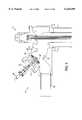
- FIG. 1is a perspective view of a manifold assembled on an outlet end of a submersible pump of a storage tank;
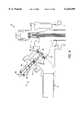
- FIG. 2is a sectional view of the manifold assembled on the pump
- FIG. 3is an enlarged view of the manifold of FIG. 2, and focusing on the check valve assembly with the lockdown member being shown in the open position;
- FIG. 4is a sectional view similar to FIG. 3 except showing the lockdown member in a closed position
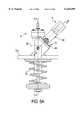
- FIG. 5Ais another enlarged view of the housing unit of FIG. 2, from another angle which shows the check valve and pressure relief valve assemblies;
- FIG. 5Bis an exploded view of the check valve assembly disassembled from the manifold
- FIG. 6is a sectional view along the line I--I of FIG. 5A of the check valve assembly
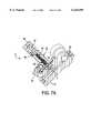
- FIG. 7Ais a sectional view along the line II--II of FIG. 5A of the pressure relief valve lockdown member
- FIG. 7Billustrates the pressure relief valve lockdown member with the protective cover removed
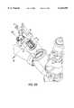
- FIG. 8illustrates a portion of the housing unit disassembled from the manifold.
- FIG. 1shows a perspective view of the manifold of the present invention mounted on a submersible pump assembly 1.
- the manifold 2includes a housing unit 3.
- the housing unit 3has a check valve assembly 4 and a pressure relief valve assembly 6, so that the check valve and pressure relief valve assemblies are formed in a single, integral unit.
- the manifold 2 constructed according to the present inventionis shown, attached to a submersible pump assembly 1.
- the manifold assemblyalso known as a header, is attached to the top of a tank port; the submersible pump 1 is suspended into the tank while attached to the manifold assembly.
- the housing unit 3is mounted to the manifold 2 and is positioned so that the housing unit 3 is positioned at a 45° angle with respect to a mounting plane 80 at which the manifold 2 is mounted on the tank port.
- the manifold 2also includes a yoke assembly 5 and a stand alone siphon port 7, as most clearly shown in FIG. 1.
- the yoke assembly 5is engaged or disengaged (shown engaged in this figure), to disconnect power to the pump during servicing.
- the stand alone siphon port 7is formed on the manifold. With this arrangement, the siphon line need not be disconnected when servicing the pump.
- FIGS. 3-6show an enlarged view of the check valve assembly 4.
- a check valve memberis in the open position, as if the pumped product is flowing.
- the check valve assembly 4includes a lockdown member 20 having one end operative to engage a check valve guide 22. The other end of the lockdown member 20 is manipulated by an operator to effect closure of the check valve assembly 4 during a pressure testing procedure to test for leaks, as described in further detail below.
- the check valve guide 22has one end portion fitted to a check valve plunger 24.
- the check valve plunger 24has a check valve seal 26 fitted on one side of the plunger 24 to effect a seal with an opening 1b of the pump manifold 2.
- a check valve retainer 28is fixed to one side of the check valve seal 26, so that the seal 26 is fitted between the plunger 24 and the retainer 28, as shown in FIGS. 3 and 6.
- FIG. 4illustrates the check valve assembly 4 when the check valve member is in a closed position.
- the lockdown member 20is fully screwed down and engaged so that the check valve seal 26 is fitted against the opening 1b.
- two O-rings 36seal and close an expansion relief port 50 of the pressure relief valve assembly 6.
- the expansion relief port 50connects the check valve assembly 4 to the pressure relief valve assembly 6, as more clearly shown in FIG. 7A.
- the lockdown member 20is in an unscrewed, upper position so that the check valve seal 26 is allowed to move freely, being biased by a check valve spring 23 and guided by the check valve guide 22.
- the valveopens against the bias of check valve spring 23 to let the fuel flow through and into the dispensing line 10.
- the valvecloses due to the bias of the check valve spring 23 when no fuel is being pumped through to the dispensing line 10.
- the check valve seal 26is forced into the closed position since the guide 22, and lockdown member 20 are set in the most downward position. In this case, no fuel can flow through the header into the dispensing line 10.
- the two O-rings 36align with either side of the expansion relief port 50, thereby sealing off the port 50 so that fuel can not flow into the pressure relief valve housing 6.
- the check valve assembly 4serves two functions. First, it assures a complete seal of the dispensing line 10 at the check valve, so that maintenance line checks can be conducted to check for leaks along the dispensing line 10. Second, it closes off the pressure relief valve assembly 6 at the expansion relief port 50. It is important to close off the pressure relief valve during leak checks because the pressure relief valve assembly 6 serves as a bypass back to an underground fuel holding tank. The structure of the check valve assembly 4 is more fully described below.
- the check valve assembly 4has a housing 30 which is fixed to the manifold 2 so that an expansion seat assembly 30a is fitted into an opening 1c of the manifold 2.
- a wiper seal housing 32is fixed to the opposite end of the housing where the lockdown member 20 protrudes from the housing 30.
- a radial wiper seal 34is fitted within the wiper seal housing 32 as shown in FIG. 6.
- an external retaining ring 38is fitted around the end of the check valve guide 22, at the portion which meets with the lockdown member 20.
- the external retaining ring 38e.g. an E-ring, serves to retain the check valve guide 22 in the housing 30, so that the check valve spring 23 can not bias the guide 22 out of the housing as the lockdown member 20 is rotated or during housing installation when the check valve guide 22 and the plunger 24 are not being biased upward by the opening 1b.
- the check valve guide 22which is located axially below the lockdown member 20 within the housing 30, moves with respect to the opening 1b so that the check valve plunger 24 and seal 26 open or close the opening 1b.
- the check valve spring 23abuts on either end to the check valve plunger 24 and the housing 30, respectively, to cause the plunger 24 and seal 26 to be biased away from the housing 30. This ensures a proper seal against the opening 1b.
- An adjustment member 40preferably but not necessarily a hexhead bolt or screw, adjusts the force of an expansion relief spring 42 biasing an expansion relief diaphragm 64 as explained below.
- One end of the adjustment member 40abuts against the expansion relief spring 42, both being housed in an expansion relief body 60.
- One end of the spring 42is biased against an expansion relief plunger 62 so that the expansion relief diaphragm 64 is biased by the force of the spring 42 as the spring is adjusted by the adjustment member 40 being turned by an operator.
- a protective cap 44is fitted at one end of the expansion relief body 60 so as to cover the second end of the adjustment member 40.
- FIG. 7Ashows the diaphragm in a closed position.
- the adjustment member 40is turned one way so as to increase the force of the spring 42 acting against the plunger 62 and the diaphragm 64 thereby increasing the line relief pressure, or turned in the opposite direction to decrease the force of the spring 42 acting against the plunger 62 and the diaphragm 64, thereby decreasing the line relief pressure.
- the line relief pressurecan be adjustably set between approximately 0 to 50 psi.
- the pressure relief valveis set at a desired setting, e.g. 23-28 psi. At this setting, extra fuel flows through the check valve assembly into the expansion relief port 50, and into pressure relief valve housing 6. If the pressure of the fuel exceeds the setting of the pressure relief valve, the diaphragm 64 floats upward away from a seat 71 to allow the fuel to flow up from an annular area 70 and down through a passage 71' in the seat 71, and out a port 72 into a chamber port in the manifold (not shown) which leads back to the fuel holding tank (not shown). In other words, the extra fuel is bypassed back to the fuel holding tank.
- a desired settinge.g. 23-28 psi.
- the pumped productflows from the check valve assembly 4, through the expansion relief port 50 into the pressure relief valve assembly 6 and exits through the port 72 leading back into the holding tank.
- expansion relief body 60is attached to the housing 30 by screws 46 and spring lockwashers 48 as shown in FIG. 5a.
- the check valve assembly 4 and pressure relief valve assembly 6are located adjacent to one another on a single body to allow easy adjustments for operating the pumping assembly and for performing line maintenance tests.
- the housing unit 3is assembled onto the manifold 2, as best illustrated in FIGS. 5B and 8.
- the check valve guide 22, being attached to the check valve plunger 24 and check valve seal 26,is fitted through the check valve spring 23 so as to be inserted within the housing 30.
- the springis compressed slightly and the external retaining ring 38 is then inserted into a groove of the check valve guide 22, so that the check valve guide is retained in the housing 30.
- the check valve assembly 4is then lowered into the manifold. Thereafter, the housing unit 3 is fastened to the manifold 2 by bolts, or the like.
- the housing unitWhen disassembling the housing unit 3 from the manifold 2, the housing unit is pulled straight out of the manifold.
- the check valve guide 22 and associated check valve plunger 24 and seal 26,are removed from the check valve assembly 4 by compressing the check valve plunger 24 towards the housing 30 so that the spring 23 is compressed. This provides for the removal of the retaining ring 38 from the check valve guide 22.
- the check valve guide 22can be removed from the housing 30.
- the check valve lockdown member 20can be assembled onto the check valve housing 30 as follows. First, the O-rings 36 are fitted onto the lockdown member 20 as shown in FIG. 8. The O-rings should be installed from the non-threaded end of the lockdown member 20 to avoid damaging the O-rings 36. The O-rings 36 should be sparingly lubricated before the lockdown member 20 is fitted into the housing 30. The wiper seal housing 32 is then fitted over the lockdown member 20 and onto the housing 30. Again, the radial wiper seal 34 should be lubricated before sliding over the lockdown member 20, so as to avoid damaging the seal 34.
Landscapes
- Engineering & Computer Science (AREA)
- General Engineering & Computer Science (AREA)
- Mechanical Engineering (AREA)
- Check Valves (AREA)
Abstract
Description
Claims (14)
Priority Applications (1)
| Application Number | Priority Date | Filing Date | Title |
|---|---|---|---|
| US09/285,890US6126409A (en) | 1999-04-07 | 1999-04-07 | Integral housing unit having a lockdown check valve and a pressure relief valve for a submersible pump and method of assembling the same |
Applications Claiming Priority (1)
| Application Number | Priority Date | Filing Date | Title |
|---|---|---|---|
| US09/285,890US6126409A (en) | 1999-04-07 | 1999-04-07 | Integral housing unit having a lockdown check valve and a pressure relief valve for a submersible pump and method of assembling the same |
Publications (1)
| Publication Number | Publication Date |
|---|---|
| US6126409Atrue US6126409A (en) | 2000-10-03 |
Family
ID=23096118
Family Applications (1)
| Application Number | Title | Priority Date | Filing Date |
|---|---|---|---|
| US09/285,890Expired - Fee RelatedUS6126409A (en) | 1999-04-07 | 1999-04-07 | Integral housing unit having a lockdown check valve and a pressure relief valve for a submersible pump and method of assembling the same |
Country Status (1)
| Country | Link |
|---|---|
| US (1) | US6126409A (en) |
Cited By (14)
| Publication number | Priority date | Publication date | Assignee | Title |
|---|---|---|---|---|
| US20030230592A1 (en)* | 2002-06-18 | 2003-12-18 | Hutchinson Ray J. | Service station leak detection and recovery system |
| US6682309B2 (en) | 2002-01-22 | 2004-01-27 | John A. Reid | Submersible pump system |
| US20040045343A1 (en)* | 2002-09-10 | 2004-03-11 | Hutchinson Ray J. | Secondary containment system and method |
| US20040129726A1 (en)* | 2003-01-06 | 2004-07-08 | Hutchinson Ray J. | Dual chambered dedicated underground storage tank |
| US20040149017A1 (en)* | 2002-09-10 | 2004-08-05 | Hutchinson Ray J. | Secondary containment leak prevention and detection system and method |
| US20040182136A1 (en)* | 2003-03-17 | 2004-09-23 | Don Halla | Fuel storage tank leak prevention and detection system and method |
| US20040261504A1 (en)* | 2002-09-10 | 2004-12-30 | Hutchinson Ray J | Secondary containment leak prevention and detection system and method in fuel dispenser |
| US20040261503A1 (en)* | 2002-09-10 | 2004-12-30 | Hutchinson Ray J. | Power head secondary containment leak prevention and detection system and method |
| US20050062000A1 (en)* | 2000-02-18 | 2005-03-24 | Bartell Donald L. | Electric motor actuated stop and self-closing check valve |
| US20050211329A1 (en)* | 2004-03-24 | 2005-09-29 | Richard Dolson | Air bleed mechanism for a submersible turbine pump |
| US20070128057A1 (en)* | 2005-12-06 | 2007-06-07 | Veeder-Root Company | Motor electrical connector employing liquid immersion protection |
| US20080111088A1 (en)* | 2006-11-10 | 2008-05-15 | Roper Pump Company | Self-contained relief valve adjustment device |
| US8721267B2 (en) | 2010-05-25 | 2014-05-13 | Veeder-Root Company | Submersible pump utilizing magnetic clutch activated impeller |
| US10239745B2 (en) | 2016-01-18 | 2019-03-26 | Veeder-Root Company | Fueling station sump dehumidifying system |
Citations (20)
| Publication number | Priority date | Publication date | Assignee | Title |
|---|---|---|---|---|
| US1177019A (en)* | 1914-03-05 | 1916-03-28 | John J Coll | Valve. |
| US2149602A (en)* | 1937-12-24 | 1939-03-07 | Dayton Pump & Mfg Co | Pump |
| US2588527A (en)* | 1944-04-13 | 1952-03-11 | Niles Bement Pond Co | Relief valve construction |
| US2652948A (en)* | 1947-03-08 | 1953-09-22 | Moore James Ballard | Control system for plurality of liquid dispensing devices |
| US2788192A (en)* | 1950-04-28 | 1957-04-09 | Shell Dev | Fluid flow and pressure control valve |
| US2821993A (en)* | 1956-08-08 | 1958-02-04 | Gilbert & Barker Mfg Co | Establishing and maintaining means for siphon connection between liquid storage tanks |
| US2840119A (en)* | 1956-07-25 | 1958-06-24 | Symington Wayne Corp | Pumping assembly |
| US2952389A (en)* | 1958-11-03 | 1960-09-13 | Red Jacket Mfg Co | Leak detecting apparatus |
| US2986308A (en)* | 1958-01-13 | 1961-05-30 | Gilbert & Barker Mfg Co | Submersible pump mounting apparatus |
| US3010470A (en)* | 1953-01-15 | 1961-11-28 | Tokheim Corp | Siphon priming apparatus |
| US3114391A (en)* | 1961-02-23 | 1963-12-17 | Westinghouse Air Brake Co | Combined check and choke valve device |
| US3172567A (en)* | 1963-02-25 | 1965-03-09 | Red Jacket Mfg Co | Header for gasoline pumping systems |
| US3183723A (en)* | 1962-12-19 | 1965-05-18 | Red Jacket Mfg Co | Leak detector |
| US3197085A (en)* | 1963-01-16 | 1965-07-27 | Red Jacket Mfg Company | Header construction with interlock electrical disconnect |
| US3592224A (en)* | 1968-12-20 | 1971-07-13 | Tech Et Commercial D Installat | Relief valve |
| US3910102A (en)* | 1974-05-17 | 1975-10-07 | F Ronald Mclean | Liquid volumetric line leak testing apparatus and method |
| US3940020A (en)* | 1973-08-23 | 1976-02-24 | Gilbert & Baker Manufacturing Company | Leak detection system and method |
| US4646700A (en)* | 1985-04-17 | 1987-03-03 | Walbro Corporation | Pressure regulator for liquid fuel system |
| US5007614A (en)* | 1989-06-22 | 1991-04-16 | Hanford N. Lockwood | Pressure responsive two-way shut-off valve |
| US5143115A (en)* | 1992-02-11 | 1992-09-01 | Delta Power Hydraulic Co. | Bi-directional pressure relief valve |
- 1999
- 1999-04-07USUS09/285,890patent/US6126409A/ennot_activeExpired - Fee Related
Patent Citations (20)
| Publication number | Priority date | Publication date | Assignee | Title |
|---|---|---|---|---|
| US1177019A (en)* | 1914-03-05 | 1916-03-28 | John J Coll | Valve. |
| US2149602A (en)* | 1937-12-24 | 1939-03-07 | Dayton Pump & Mfg Co | Pump |
| US2588527A (en)* | 1944-04-13 | 1952-03-11 | Niles Bement Pond Co | Relief valve construction |
| US2652948A (en)* | 1947-03-08 | 1953-09-22 | Moore James Ballard | Control system for plurality of liquid dispensing devices |
| US2788192A (en)* | 1950-04-28 | 1957-04-09 | Shell Dev | Fluid flow and pressure control valve |
| US3010470A (en)* | 1953-01-15 | 1961-11-28 | Tokheim Corp | Siphon priming apparatus |
| US2840119A (en)* | 1956-07-25 | 1958-06-24 | Symington Wayne Corp | Pumping assembly |
| US2821993A (en)* | 1956-08-08 | 1958-02-04 | Gilbert & Barker Mfg Co | Establishing and maintaining means for siphon connection between liquid storage tanks |
| US2986308A (en)* | 1958-01-13 | 1961-05-30 | Gilbert & Barker Mfg Co | Submersible pump mounting apparatus |
| US2952389A (en)* | 1958-11-03 | 1960-09-13 | Red Jacket Mfg Co | Leak detecting apparatus |
| US3114391A (en)* | 1961-02-23 | 1963-12-17 | Westinghouse Air Brake Co | Combined check and choke valve device |
| US3183723A (en)* | 1962-12-19 | 1965-05-18 | Red Jacket Mfg Co | Leak detector |
| US3197085A (en)* | 1963-01-16 | 1965-07-27 | Red Jacket Mfg Company | Header construction with interlock electrical disconnect |
| US3172567A (en)* | 1963-02-25 | 1965-03-09 | Red Jacket Mfg Co | Header for gasoline pumping systems |
| US3592224A (en)* | 1968-12-20 | 1971-07-13 | Tech Et Commercial D Installat | Relief valve |
| US3940020A (en)* | 1973-08-23 | 1976-02-24 | Gilbert & Baker Manufacturing Company | Leak detection system and method |
| US3910102A (en)* | 1974-05-17 | 1975-10-07 | F Ronald Mclean | Liquid volumetric line leak testing apparatus and method |
| US4646700A (en)* | 1985-04-17 | 1987-03-03 | Walbro Corporation | Pressure regulator for liquid fuel system |
| US5007614A (en)* | 1989-06-22 | 1991-04-16 | Hanford N. Lockwood | Pressure responsive two-way shut-off valve |
| US5143115A (en)* | 1992-02-11 | 1992-09-01 | Delta Power Hydraulic Co. | Bi-directional pressure relief valve |
Cited By (46)
| Publication number | Priority date | Publication date | Assignee | Title |
|---|---|---|---|---|
| US7249748B2 (en) | 2000-02-18 | 2007-07-31 | Ga Industries, Inc. | Electric motor actuated stop and self-closing check valve |
| US20050269535A1 (en)* | 2000-02-18 | 2005-12-08 | Ga Industries Inc. | Electric motor actuated stop and self-closing check valve |
| US8465000B2 (en) | 2000-02-18 | 2013-06-18 | Ga Industries, Llc | Electric motor actuated stop and self-closing check valve |
| US6929238B2 (en)* | 2000-02-18 | 2005-08-16 | Ga Industries Inc. | Electric motor actuated stop and self-closing check valve |
| US20080061257A1 (en)* | 2000-02-18 | 2008-03-13 | Ga Industries Inc. | Electric motor actuated stop and self-closing check valve |
| US20050062000A1 (en)* | 2000-02-18 | 2005-03-24 | Bartell Donald L. | Electric motor actuated stop and self-closing check valve |
| US6682309B2 (en) | 2002-01-22 | 2004-01-27 | John A. Reid | Submersible pump system |
| US20050205157A1 (en)* | 2002-06-18 | 2005-09-22 | Gilbarco Inc. | Service station leak detection and recovery system |
| US20030230593A1 (en)* | 2002-06-18 | 2003-12-18 | Hutchinson Ray J. | Service station leak detection and recovery system |
| US6962269B2 (en) | 2002-06-18 | 2005-11-08 | Gilbarco Inc. | Service station leak detection and recovery system |
| US6974054B2 (en) | 2002-06-18 | 2005-12-13 | Gilbarco Inc. | Service station leak detection with recovery system |
| US20030230592A1 (en)* | 2002-06-18 | 2003-12-18 | Hutchinson Ray J. | Service station leak detection and recovery system |
| US6935161B2 (en) | 2002-06-18 | 2005-08-30 | Gilbarco Inc. | Service station leak detection and recovery system |
| US20050034508A1 (en)* | 2002-06-18 | 2005-02-17 | Hutchinson Ray J. | Service station leak detection and recovery system |
| US7455194B2 (en) | 2002-06-18 | 2008-11-25 | Gilbarco Inc. | Service station leak detection and recovery system |
| US20040261504A1 (en)* | 2002-09-10 | 2004-12-30 | Hutchinson Ray J | Secondary containment leak prevention and detection system and method in fuel dispenser |
| US7010961B2 (en) | 2002-09-10 | 2006-03-14 | Gilbarco Inc. | Power head secondary containment leak prevention and detection system and method |
| US20050145015A1 (en)* | 2002-09-10 | 2005-07-07 | Gilbarco Inc. | Secondary containment leak prevention and detection system and method |
| US20050039518A1 (en)* | 2002-09-10 | 2005-02-24 | Hutchinson Ray J. | Secondary containment leak prevention and detection system and method |
| US20040261503A1 (en)* | 2002-09-10 | 2004-12-30 | Hutchinson Ray J. | Power head secondary containment leak prevention and detection system and method |
| US20040045343A1 (en)* | 2002-09-10 | 2004-03-11 | Hutchinson Ray J. | Secondary containment system and method |
| US7251983B2 (en) | 2002-09-10 | 2007-08-07 | Gilbarco Inc. | Secondary containment system and method |
| US20040149017A1 (en)* | 2002-09-10 | 2004-08-05 | Hutchinson Ray J. | Secondary containment leak prevention and detection system and method |
| US20050247111A1 (en)* | 2002-09-10 | 2005-11-10 | Gilbarco Inc. | Secondary containment leak prevention and detection system and method |
| US20050247112A1 (en)* | 2002-09-10 | 2005-11-10 | Gilbarco Inc. | Power head secondary containment leak prevention and detection system and method |
| US7225664B2 (en) | 2002-09-10 | 2007-06-05 | Gilbarco Inc. | Secondary containment leak prevention and detection system and method |
| US7080546B2 (en) | 2002-09-10 | 2006-07-25 | Gilbarco Inc. | Secondary containment leak prevention and detection system and method |
| US6978661B2 (en) | 2002-09-10 | 2005-12-27 | Gilbarco Inc. | Secondary containment leak prevention and detection system and method in fuel dispenser |
| US6978660B2 (en) | 2002-09-10 | 2005-12-27 | Gilbarco Inc. | Power head secondary containment leak prevention and detection system and method |
| US6997042B2 (en) | 2002-09-10 | 2006-02-14 | Gilbarco Inc. | Secondary containment leak prevention and detection system and method |
| US20050145016A1 (en)* | 2002-09-10 | 2005-07-07 | Gilbarco Inc. | Secondary containment leak prevention and detection system and method |
| US20060090547A1 (en)* | 2002-09-10 | 2006-05-04 | Gilbarco Inc. | Power head secondary containment leak prevention and detection system and method |
| US7051576B2 (en) | 2002-09-10 | 2006-05-30 | Gilbarco Inc. | Secondary containment leak prevention and detection system and method |
| US7076994B2 (en) | 2002-09-10 | 2006-07-18 | Gilbarco Inc. | Power head secondary containment leak prevention and detection system and method |
| WO2004060776A1 (en) | 2003-01-06 | 2004-07-22 | Gilbarco Inc. | Dual chambered dedicated underground storage tank |
| US20040129726A1 (en)* | 2003-01-06 | 2004-07-08 | Hutchinson Ray J. | Dual chambered dedicated underground storage tank |
| US20040182136A1 (en)* | 2003-03-17 | 2004-09-23 | Don Halla | Fuel storage tank leak prevention and detection system and method |
| WO2004083887A2 (en) | 2003-03-17 | 2004-09-30 | Veeder-Root Company, Inc. | Fuel storage tank leak prevention and detection system and method |
| WO2004083887A3 (en)* | 2003-03-17 | 2004-11-11 | Veeder Root Company Inc | Fuel storage tank leak prevention and detection system and method |
| US6834534B2 (en) | 2003-03-17 | 2004-12-28 | Veeder-Root Company | Fuel storage tank leak prevention and detection system and method |
| US7059366B2 (en) | 2004-03-24 | 2006-06-13 | Veeder-Root Company | Air bleed mechanism for a submersible turbine pump |
| US20050211329A1 (en)* | 2004-03-24 | 2005-09-29 | Richard Dolson | Air bleed mechanism for a submersible turbine pump |
| US20070128057A1 (en)* | 2005-12-06 | 2007-06-07 | Veeder-Root Company | Motor electrical connector employing liquid immersion protection |
| US20080111088A1 (en)* | 2006-11-10 | 2008-05-15 | Roper Pump Company | Self-contained relief valve adjustment device |
| US8721267B2 (en) | 2010-05-25 | 2014-05-13 | Veeder-Root Company | Submersible pump utilizing magnetic clutch activated impeller |
| US10239745B2 (en) | 2016-01-18 | 2019-03-26 | Veeder-Root Company | Fueling station sump dehumidifying system |
Similar Documents
| Publication | Publication Date | Title |
|---|---|---|
| US6126409A (en) | Integral housing unit having a lockdown check valve and a pressure relief valve for a submersible pump and method of assembling the same | |
| CA2165047C (en) | Backflow preventer and test cock assembly | |
| US5711341A (en) | Swing-type check valve assembly retained within a valve housing by abutting engagement with a valve cover and a port of the valve housing | |
| US6708712B2 (en) | Pressure regulator utilizing a disc spring | |
| US3837358A (en) | Backflow preventer valve assembly | |
| US5794655A (en) | Swing-type check valve assembly having an integrated valve seat and valve housing cover | |
| US7302961B2 (en) | Surge relief valve | |
| US6694996B2 (en) | Swing check backflow preventor having check valve with lever arm | |
| US8627846B2 (en) | Pressure regulator having an integral pilot and self-relieving mechanism | |
| US6311723B1 (en) | Flow control valve assembly | |
| US12128336B2 (en) | Fuel filter assembly | |
| JP2014516398A (en) | In-line back pressure fluid regulator | |
| US4637439A (en) | Mini-regulator valve assembly | |
| CN107654702B (en) | One-way valve | |
| US2364812A (en) | Poppet valve | |
| US7004186B2 (en) | Surge relief apparatus for a valve | |
| US4718450A (en) | Pressure relief valve | |
| US5996606A (en) | Four-port valve and three-way valve | |
| US20210299598A1 (en) | Fuel filter assembly | |
| AU2018220011B2 (en) | Spill-resistant vacuum breaker valve | |
| US20080047612A1 (en) | Automatic draining double check vacuum breaker | |
| US4638831A (en) | Valve arrangement for unloading liquid flow at a non-return valve | |
| US7389791B2 (en) | Backflow preventer | |
| NO20140105A1 (en) | REGULATORS WITH ISOLATED FILLING ROOMS AND EQUIPMENT FOR EXHAUST PROTECTION | |
| US10718458B2 (en) | Automated pressure equalization above and below completion plug of gate valve cartridge or a completion plug of a line stop fitting |
Legal Events
| Date | Code | Title | Description |
|---|---|---|---|
| AS | Assignment | Owner name:MARLEY PUMP, IOWA Free format text:ASSIGNMENT OF ASSIGNORS INTEREST;ASSIGNOR:YOUNG, DAVID S.;REEL/FRAME:009898/0708 Effective date:19990329 | |
| AS | Assignment | Owner name:CHASE MANHATTAN BANK AS COLLATERAL AGENT, THE, TEX Free format text:SECURITY INTEREST;ASSIGNOR:MARLEY COMPANY (DE CORPORATION), THE;REEL/FRAME:012219/0449 Effective date:20010710 | |
| FPAY | Fee payment | Year of fee payment:4 | |
| AS | Assignment | Owner name:THE MARLEY COMPANY LLC (FORMERLY KNOWN AS THE MARL Free format text:TERMINATION AND RELEASE OF SECURITY INTEREST IN PATENT RIGHTS (PREVIOUSLY RECORDED AT REEL 12219 FRAME 0449);ASSIGNOR:JPMORGAN CHASE BANK, N.A., AS COLLATERAL AGENT;REEL/FRAME:016851/0796 Effective date:20051118 | |
| REMI | Maintenance fee reminder mailed | ||
| LAPS | Lapse for failure to pay maintenance fees | ||
| LAPS | Lapse for failure to pay maintenance fees | Free format text:PATENT EXPIRED FOR FAILURE TO PAY MAINTENANCE FEES (ORIGINAL EVENT CODE: EXP.); ENTITY STATUS OF PATENT OWNER: LARGE ENTITY | |
| STCH | Information on status: patent discontinuation | Free format text:PATENT EXPIRED DUE TO NONPAYMENT OF MAINTENANCE FEES UNDER 37 CFR 1.362 | |
| FP | Lapsed due to failure to pay maintenance fee | Effective date:20081003 |