US6125928A - System for controlling and stopping oil drilling fires - Google Patents
System for controlling and stopping oil drilling firesDownload PDFInfo
- Publication number
- US6125928A US6125928AUS09/332,681US33268199AUS6125928AUS 6125928 AUS6125928 AUS 6125928AUS 33268199 AUS33268199 AUS 33268199AUS 6125928 AUS6125928 AUS 6125928A
- Authority
- US
- United States
- Prior art keywords
- valve equipment
- pipe
- cylinder
- drilling
- plugging
- Prior art date
- Legal status (The legal status is an assumption and is not a legal conclusion. Google has not performed a legal analysis and makes no representation as to the accuracy of the status listed.)
- Expired - Lifetime
Links
Images


Classifications
- E—FIXED CONSTRUCTIONS
- E21—EARTH OR ROCK DRILLING; MINING
- E21B—EARTH OR ROCK DRILLING; OBTAINING OIL, GAS, WATER, SOLUBLE OR MELTABLE MATERIALS OR A SLURRY OF MINERALS FROM WELLS
- E21B34/00—Valve arrangements for boreholes or wells
- E21B34/02—Valve arrangements for boreholes or wells in well heads
- E—FIXED CONSTRUCTIONS
- E21—EARTH OR ROCK DRILLING; MINING
- E21B—EARTH OR ROCK DRILLING; OBTAINING OIL, GAS, WATER, SOLUBLE OR MELTABLE MATERIALS OR A SLURRY OF MINERALS FROM WELLS
- E21B29/00—Cutting or destroying pipes, packers, plugs or wire lines, located in boreholes or wells, e.g. cutting of damaged pipes, of windows; Deforming of pipes in boreholes or wells; Reconditioning of well casings while in the ground
- E21B29/08—Cutting or deforming pipes to control fluid flow
- E—FIXED CONSTRUCTIONS
- E21—EARTH OR ROCK DRILLING; MINING
- E21B—EARTH OR ROCK DRILLING; OBTAINING OIL, GAS, WATER, SOLUBLE OR MELTABLE MATERIALS OR A SLURRY OF MINERALS FROM WELLS
- E21B34/00—Valve arrangements for boreholes or wells
- E21B34/16—Control means therefor being outside the borehole
- Y—GENERAL TAGGING OF NEW TECHNOLOGICAL DEVELOPMENTS; GENERAL TAGGING OF CROSS-SECTIONAL TECHNOLOGIES SPANNING OVER SEVERAL SECTIONS OF THE IPC; TECHNICAL SUBJECTS COVERED BY FORMER USPC CROSS-REFERENCE ART COLLECTIONS [XRACs] AND DIGESTS
- Y10—TECHNICAL SUBJECTS COVERED BY FORMER USPC
- Y10T—TECHNICAL SUBJECTS COVERED BY FORMER US CLASSIFICATION
- Y10T137/00—Fluid handling
- Y10T137/598—With repair, tapping, assembly, or disassembly means
- Y10T137/612—Tapping a pipe, keg, or apertured tank under pressure
- Y10T137/6123—With aperture forming means
Definitions
- the subject of the inventionis a system to controll oil drilling fires or fires of other corresponding liauid substances.
- the eruption of burning substanceis stopped so that the oil drilling pipe/pipes are blocked in a way which makes it possible for the pipes to be reopened.
- Wateris sprayed on the seat of the fire while the fire fighter at the same time approaches the fire behind a protective shield and tries to shut down the valve of the oil pipe manually.
- the methodis dangerous and requires a lot of water, which is not always available at the site of the fire.
- the main parts of the equipment of this invention in questionare: a hydraulic cylinder, a piston, a drilling cylinder, a plugging cylinder, a drill, a box clamp, a hydraulic motor or other power source, a blocking bolt, a hydraulic container with leads and a pressure battery and an automatic control and surveillance system.
- each oil and/or gas drilling pipe within each otherhas its own drilling unit in accordance with pipe size.
- the drilling unitwe mean the drilling and plugging mechanism needed to close one oil or gas drilling pipe.
- Several drilling unitscan use a mutual energy source with its hydraulic container. In underwater conditions as on offshore oil drilling platforms the water pressure can be directed with its own mechanism to be used in the system.
- the purpose of the system of this inventionis to controll oil and/or gas fires so that the distruction of big oil and/or gas drilling equipment can be avoided.
- the equipmentcan be installed either to an oil and/or gas drilling system under construction, an oil and/or gas drilling system already constructed or even onto a burning one. Because the equipment is remote-installed and automatically controlled the oil fire does not pose a threat to humans, when the equipment has already been installed to the oil drilling system in advance and installing one on an already burning system does not necessitate going into the immediate proximity of the fire seat, on the contrary it is installed underground.
- the equipment and methodare safe, they save the environment, money and oil or gas.
- FIG. 1shows a cross section of the equipment when the first drilling cylinder is in motion.
- FIG. 2shows a cross section of the equipment when the first plugging cylinder is in place.
- FIG. 3shows a cross section of the equipment when all three plugging cylinders are in place.
- FIG. 4shows a cross section of the hemispherical cylinder.
- FIG. 5shows a part cross section of the conical cylinder with the grinding surface.
- FIG. 6shows a part cross section of the conical cylinder with protruding blade.
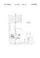
- FIG. 7shows the equipment installed and a part cross section of the hydraulic container. The figure does not shows the the space constructed under ground, where the equipment is situated.
- FIG. 8is a picture detailing the box clamp and the locked blocking bolt.
- FIG. 9shows an application in which the drilling cylinder and the plugging cylinder (which, however, are not drawn into the figure) operate beginning from the same side of the oil and/or gas drilling pipe and the above mentioned cylinders are directed by and the cutting seam sealed by means of a stuffing box.
- the stuffing box on the right hand sidehas not been tightened into place.
- FIGS. 1, 2 and 3the idea is that on the right hand side of the oil and/or gas drilling pipes and the plugging cylinder there is a similar pushing and/or rotating mechanism as on the left side of the oil and/or gas drilling pipes. It is also appropriate, deviating from the drawings, that drilling units operating one after the other are placed on opposite sides of the oil and/or gas drilling pipes so that successive drillings as well as pluggings are done starting from the opposite sides of the pipes. If there are three or more drilling units around the same oil and/or gas drilling pipes each can be placed to be started from completely different directions, thus making it possible to minimize resultant force caused to the pipes by the drilling and plugging.
- the plugging cylinderscan operate either only so they are pushed or they can be equipped with a rotating motor for example for grinding.
- a pressurized fire extinguishing substancesuch as liquid nitrogen can additionally be fed into the gas or oil drilling pipe.
- Thisis fed through a hole cut into the oil or gas drilling pipe by a device like the drilling cylinder 3. All this can be done without electricity, by forced controll, in which case once the operation is started it cannot be stopped.
- the equipmentis fixed around the oil pipes with a box clamp 6 and supported to its base. By plugging pipes of various sizes separately the pipes on top are prevented from falling. By installing sleeve pipes in place of the cut ones and by pulling out the plugs the oil drilling system can be made operational again.
- the inventionalso includes a stuffing box 14, a tightener 15, blocking locks 16, a plain bearing (for example a chrome strip) 17, compressed oil packing 18, a locking groove 19 and a frame groove 20.
- the end of the stuffing box 14 which is facing the oil or gas drilling pipeis shaped in the form of the outside wall of the pipe in question and is very sharp, this is tightened into place with a plain bearing 17 and a tightener 15 with an outside thread to the inner thread of the frame 12 of the equipment either by hand during installation or by an automatized mechanism when the equipment is started.
- a locking groove 19has been shaped around the tightener 15 of the stuffing box, into which the blocking locks 16 drawn to the frame 12 by springs/fluid pressure are pushed, when the tightener of the stuffing box has been pushed to the required depth. Additionally a frame groove 20 has been shaped into the frame 12 of the equipment, its purpose being to prevent, in addition to the tightener 15 of the stuffing box, the loosening of the stuffing box 14 when it has reached the fixed depth.
- the purpose of the stuffing box 14which has been tightened into place and which is very sharp at the oil or gas drilling pipe 7 end and which is of a very hard material, is to seal the plugging seam of the oil or gas drilling pipe 7 being drilled and plugged and to direct the movement of the drilling-plugging combination 3-4 travelling within it.
- the seam between the stuffing box 14 and the axle 13is sealed with a compressed oil packing.
- the surveillance and control of the valvecan operate:
- the operationscan be connected either manually or automatically, in which case the system is started by the safety release of the independently closing system.
- measuring quantitieswe can use temperature, gas content, pressure, flow, jolts, mechanics, electrical techniques or other such quantities, which give the valve instructions automatically also when it is not possible to do this by human power.
- Sensors indicating operationcan be installed on the valve which will show the operating status of the valve.
- a pressure sensor in the hydraulic container showing the valvehas started operating, indicating the working pressure of the oil.
- a gauge showing the amount of oil indicating the distance of motion:
- the pressure sensor on the return side of the cylinderindicates the operation of the return motion.
- the pressure sensor in the plugging cylinderindicates the plugging motion.
- the sensor indicating the rotating of the drillis situated on the axle of the drill
- a sensor situated in the tip of the drillcan measure prevailing quantities.
- Automatic data processinguses these quantities to form a picture detailing the operation of the valve onto the computer terminal.
Landscapes
- Life Sciences & Earth Sciences (AREA)
- Engineering & Computer Science (AREA)
- Geology (AREA)
- Mining & Mineral Resources (AREA)
- Physics & Mathematics (AREA)
- Environmental & Geological Engineering (AREA)
- Fluid Mechanics (AREA)
- General Life Sciences & Earth Sciences (AREA)
- Geochemistry & Mineralogy (AREA)
- Earth Drilling (AREA)
Abstract
Description
Claims (40)
Applications Claiming Priority (3)
| Application Number | Priority Date | Filing Date | Title |
|---|---|---|---|
| FI964068 | 1996-12-16 | ||
| FI964068 | 1996-12-16 | ||
| PCT/FI1997/000593WO1998027312A1 (en) | 1996-12-16 | 1997-10-01 | System for controlling and stopping oil drilling fires |
Related Parent Applications (1)
| Application Number | Title | Priority Date | Filing Date |
|---|---|---|---|
| PCT/FI1997/000593ContinuationWO1998027312A1 (en) | 1996-10-10 | 1997-10-01 | System for controlling and stopping oil drilling fires |
Publications (1)
| Publication Number | Publication Date |
|---|---|
| US6125928Atrue US6125928A (en) | 2000-10-03 |
Family
ID=26160230
Family Applications (1)
| Application Number | Title | Priority Date | Filing Date |
|---|---|---|---|
| US09/332,681Expired - LifetimeUS6125928A (en) | 1996-12-16 | 1999-06-14 | System for controlling and stopping oil drilling fires |
Country Status (1)
| Country | Link |
|---|---|
| US (1) | US6125928A (en) |
Cited By (14)
| Publication number | Priority date | Publication date | Assignee | Title |
|---|---|---|---|---|
| US20020056573A1 (en)* | 1997-01-29 | 2002-05-16 | Weatherford/Lamb, Inc. | Apparatus for positioning a tong and drilling rig provided with such an apparatus |
| US6408944B1 (en)* | 1997-12-30 | 2002-06-25 | Ab Grundstenen (Metal Patent Whss Ab) | Apparatus and method to shut down a pipeline |
| US20030015322A1 (en)* | 1997-01-29 | 2003-01-23 | Weatherford/Lamb, Inc. | Methods and apparatus for severing nested strings of tubulars |
| US20030127231A1 (en)* | 2001-12-17 | 2003-07-10 | Tye Schlegelmilch | Coiled tubing cutter |
| RU2224084C1 (en)* | 2003-04-14 | 2004-02-20 | Федеральное Государственное учреждение Аварийно-спасательное формирование Западно-Сибирская противофонтанная военизированная часть | Method of lowering lifting pipes from well opening to bottom hole during open oil gushers liquidation |
| US20080149355A1 (en)* | 2005-02-02 | 2008-06-26 | Francisco Joven Marco | Fire Extinguishing and Gas and Oil Well Recovery System |
| GB2486544A (en)* | 2010-12-15 | 2012-06-20 | Vetco Gray Inc | Emergency subsea wellhead closure device or flow diverter |
| WO2013033306A1 (en)* | 2011-09-02 | 2013-03-07 | Shell Oil Company | Well emergency separation tool for use in separating a tubular element |
| US8794308B1 (en)* | 2013-07-21 | 2014-08-05 | Milanovich Investments, L.L.C. | Blowout preventer and flow regulator |
| US8794333B1 (en)* | 2013-07-02 | 2014-08-05 | Milanovich Investments, L.L.C. | Combination blowout preventer and recovery device |
| WO2016022631A1 (en)* | 2014-08-07 | 2016-02-11 | Shell Oil Company | Kinetic shear ram |
| US9784062B1 (en)* | 2016-03-18 | 2017-10-10 | Horacio Solis | Pipe cutting and plugging device |
| US10119354B2 (en) | 2010-10-29 | 2018-11-06 | Shell Oil Company | Well emergency separation tool for use in separating a tubular element |
| US11098551B2 (en) | 2015-05-01 | 2021-08-24 | Kinetic Pressure Control Ltd. | Blowout preventer |
Citations (22)
| Publication number | Priority date | Publication date | Assignee | Title |
|---|---|---|---|---|
| US2000381A (en)* | 1931-07-28 | 1935-05-07 | Peter J Duffy | Means for extinguishing oil well fires |
| US2840166A (en)* | 1955-07-05 | 1958-06-24 | Exxon Research Engineering Co | Apparatus for closing wild wells through a pressure chamber |
| US3277964A (en)* | 1962-02-17 | 1966-10-11 | Houpeurt Andre | Method for controlling the discharge of combustible fluid from oil wells and the like |
| US3647174A (en)* | 1970-09-25 | 1972-03-07 | Hydril Co | Blowout preventer |
| US3716068A (en)* | 1971-06-11 | 1973-02-13 | F Addison | Surface controlled blowout arrester |
| US3717202A (en)* | 1971-08-30 | 1973-02-20 | M Burrow | Remote well plugging apparatus |
| US3905424A (en)* | 1971-11-26 | 1975-09-16 | Albert A Elwood | Cryogenic control valve |
| US3993137A (en)* | 1974-05-31 | 1976-11-23 | Uriel Hefetz | Method and device for extinguishing fires in oil wells |
| US4095421A (en)* | 1976-01-26 | 1978-06-20 | Chevron Research Company | Subsea energy power supply |
| US4193574A (en)* | 1978-10-27 | 1980-03-18 | Barnes Johney H | Well shut off device |
| US4440232A (en)* | 1982-07-26 | 1984-04-03 | Koomey, Inc. | Well pressure compensation for blowout preventers |
| US4626135A (en)* | 1984-10-22 | 1986-12-02 | Hydril Company | Marine riser well control method and apparatus |
| US5074518A (en)* | 1990-11-02 | 1991-12-24 | Hydratech | Proportional annular B.O.P. controller |
| US5076311A (en)* | 1991-05-09 | 1991-12-31 | Marquip Inc. | Directly installed shut-off valve assembly for flowing high pressure line |
| WO1992016714A1 (en)* | 1991-03-15 | 1992-10-01 | Stroem Einar | Apparatus and method for suppressing an uncontrolled blow-out or fire in an oil well |
| US5156212A (en)* | 1991-05-21 | 1992-10-20 | Bryant Thomas B | Method and system for controlling high pressure flow, such as in containment of oil and gas well fires |
| US5161617A (en)* | 1991-07-29 | 1992-11-10 | Marquip, Inc. | Directly installed shut-off and diverter valve assembly for flowing oil well with concentric casings |
| DE4116473A1 (en)* | 1991-05-21 | 1992-11-26 | Janssen Hermann J | Sealing riser in casing of burning oil or gas prodn. well - by driving access tunnel, boring transverse hole through riser, sealing riser, and fitting stop valve to control resumed flow |
| US5199493A (en)* | 1991-05-03 | 1993-04-06 | Sodder George Jr | Methods and apparatus for shutting a conduit |
| US5217073A (en)* | 1991-05-07 | 1993-06-08 | Karsten Bruns | Cut-and-close device for pressure pipes in production and supply installations |
| US5280823A (en)* | 1991-12-04 | 1994-01-25 | Steve Chabot | Apparatus for regaining control over oil and gas flowing from "blow out" wells |
| US5623994A (en)* | 1992-03-11 | 1997-04-29 | Wellcutter, Inc. | Well head cutting and capping system |
- 1999
- 1999-06-14USUS09/332,681patent/US6125928A/ennot_activeExpired - Lifetime
Patent Citations (22)
| Publication number | Priority date | Publication date | Assignee | Title |
|---|---|---|---|---|
| US2000381A (en)* | 1931-07-28 | 1935-05-07 | Peter J Duffy | Means for extinguishing oil well fires |
| US2840166A (en)* | 1955-07-05 | 1958-06-24 | Exxon Research Engineering Co | Apparatus for closing wild wells through a pressure chamber |
| US3277964A (en)* | 1962-02-17 | 1966-10-11 | Houpeurt Andre | Method for controlling the discharge of combustible fluid from oil wells and the like |
| US3647174A (en)* | 1970-09-25 | 1972-03-07 | Hydril Co | Blowout preventer |
| US3716068A (en)* | 1971-06-11 | 1973-02-13 | F Addison | Surface controlled blowout arrester |
| US3717202A (en)* | 1971-08-30 | 1973-02-20 | M Burrow | Remote well plugging apparatus |
| US3905424A (en)* | 1971-11-26 | 1975-09-16 | Albert A Elwood | Cryogenic control valve |
| US3993137A (en)* | 1974-05-31 | 1976-11-23 | Uriel Hefetz | Method and device for extinguishing fires in oil wells |
| US4095421A (en)* | 1976-01-26 | 1978-06-20 | Chevron Research Company | Subsea energy power supply |
| US4193574A (en)* | 1978-10-27 | 1980-03-18 | Barnes Johney H | Well shut off device |
| US4440232A (en)* | 1982-07-26 | 1984-04-03 | Koomey, Inc. | Well pressure compensation for blowout preventers |
| US4626135A (en)* | 1984-10-22 | 1986-12-02 | Hydril Company | Marine riser well control method and apparatus |
| US5074518A (en)* | 1990-11-02 | 1991-12-24 | Hydratech | Proportional annular B.O.P. controller |
| WO1992016714A1 (en)* | 1991-03-15 | 1992-10-01 | Stroem Einar | Apparatus and method for suppressing an uncontrolled blow-out or fire in an oil well |
| US5199493A (en)* | 1991-05-03 | 1993-04-06 | Sodder George Jr | Methods and apparatus for shutting a conduit |
| US5217073A (en)* | 1991-05-07 | 1993-06-08 | Karsten Bruns | Cut-and-close device for pressure pipes in production and supply installations |
| US5076311A (en)* | 1991-05-09 | 1991-12-31 | Marquip Inc. | Directly installed shut-off valve assembly for flowing high pressure line |
| US5156212A (en)* | 1991-05-21 | 1992-10-20 | Bryant Thomas B | Method and system for controlling high pressure flow, such as in containment of oil and gas well fires |
| DE4116473A1 (en)* | 1991-05-21 | 1992-11-26 | Janssen Hermann J | Sealing riser in casing of burning oil or gas prodn. well - by driving access tunnel, boring transverse hole through riser, sealing riser, and fitting stop valve to control resumed flow |
| US5161617A (en)* | 1991-07-29 | 1992-11-10 | Marquip, Inc. | Directly installed shut-off and diverter valve assembly for flowing oil well with concentric casings |
| US5280823A (en)* | 1991-12-04 | 1994-01-25 | Steve Chabot | Apparatus for regaining control over oil and gas flowing from "blow out" wells |
| US5623994A (en)* | 1992-03-11 | 1997-04-29 | Wellcutter, Inc. | Well head cutting and capping system |
Cited By (24)
| Publication number | Priority date | Publication date | Assignee | Title |
|---|---|---|---|---|
| US20020056573A1 (en)* | 1997-01-29 | 2002-05-16 | Weatherford/Lamb, Inc. | Apparatus for positioning a tong and drilling rig provided with such an apparatus |
| US20030015322A1 (en)* | 1997-01-29 | 2003-01-23 | Weatherford/Lamb, Inc. | Methods and apparatus for severing nested strings of tubulars |
| US6827145B2 (en)* | 1997-01-29 | 2004-12-07 | Weatherford/Lamb, Inc. | Methods and apparatus for severing nested strings of tubulars |
| US7225865B2 (en) | 1997-01-29 | 2007-06-05 | Weatherford/Lamb, Inc. | Apparatus for positioning a tong and drilling rig provided with such an apparatus |
| US6408944B1 (en)* | 1997-12-30 | 2002-06-25 | Ab Grundstenen (Metal Patent Whss Ab) | Apparatus and method to shut down a pipeline |
| US20030127231A1 (en)* | 2001-12-17 | 2003-07-10 | Tye Schlegelmilch | Coiled tubing cutter |
| US7086467B2 (en)* | 2001-12-17 | 2006-08-08 | Schlumberger Technology Corporation | Coiled tubing cutter |
| US20060254773A1 (en)* | 2001-12-17 | 2006-11-16 | Schlumberger Technology Corporation | Coiled tubing cutter |
| US7225873B2 (en)* | 2001-12-17 | 2007-06-05 | Schlumberger Technology Corporation | Coiled tubing cutter |
| RU2224084C1 (en)* | 2003-04-14 | 2004-02-20 | Федеральное Государственное учреждение Аварийно-спасательное формирование Западно-Сибирская противофонтанная военизированная часть | Method of lowering lifting pipes from well opening to bottom hole during open oil gushers liquidation |
| US20080149355A1 (en)* | 2005-02-02 | 2008-06-26 | Francisco Joven Marco | Fire Extinguishing and Gas and Oil Well Recovery System |
| US10119354B2 (en) | 2010-10-29 | 2018-11-06 | Shell Oil Company | Well emergency separation tool for use in separating a tubular element |
| US20120152561A1 (en)* | 2010-12-15 | 2012-06-21 | Vetco Gray Inc. | Emergency subsea wellhead closure devices |
| US8622139B2 (en)* | 2010-12-15 | 2014-01-07 | Vetco Gray Inc. | Emergency subsea wellhead closure devices |
| GB2486544A (en)* | 2010-12-15 | 2012-06-20 | Vetco Gray Inc | Emergency subsea wellhead closure device or flow diverter |
| WO2013033306A1 (en)* | 2011-09-02 | 2013-03-07 | Shell Oil Company | Well emergency separation tool for use in separating a tubular element |
| GB2509409A (en)* | 2011-09-02 | 2014-07-02 | Shell Int Research | Well emergency separation tool for use in separating a tubular element |
| US9982500B2 (en) | 2011-09-02 | 2018-05-29 | Shell Oil Company | Well emergency separation tool for use in separating a tubular element |
| GB2509409B (en)* | 2011-09-02 | 2018-12-19 | Shell Int Research | Well emergency separation tool for use in separating a tubular element |
| US8794333B1 (en)* | 2013-07-02 | 2014-08-05 | Milanovich Investments, L.L.C. | Combination blowout preventer and recovery device |
| US8794308B1 (en)* | 2013-07-21 | 2014-08-05 | Milanovich Investments, L.L.C. | Blowout preventer and flow regulator |
| WO2016022631A1 (en)* | 2014-08-07 | 2016-02-11 | Shell Oil Company | Kinetic shear ram |
| US11098551B2 (en) | 2015-05-01 | 2021-08-24 | Kinetic Pressure Control Ltd. | Blowout preventer |
| US9784062B1 (en)* | 2016-03-18 | 2017-10-10 | Horacio Solis | Pipe cutting and plugging device |
Similar Documents
| Publication | Publication Date | Title |
|---|---|---|
| US6125928A (en) | System for controlling and stopping oil drilling fires | |
| US4463814A (en) | Down-hole drilling apparatus | |
| US3888319A (en) | Control system for a drilling apparatus | |
| CA2374986C (en) | Tubular cutting tool | |
| US3766979A (en) | Well casing cutter and sealer | |
| US4512422A (en) | Apparatus for drilling oil and gas wells and a torque arrestor associated therewith | |
| US6412578B1 (en) | Boring apparatus | |
| US5076311A (en) | Directly installed shut-off valve assembly for flowing high pressure line | |
| CA1230544A (en) | Weight actuated tubing valve | |
| US10801292B2 (en) | Blowout preventer stack | |
| US20170138150A1 (en) | Repositionable Well Plug | |
| US5183364A (en) | Device for installing an in-line valve | |
| BRPI1105199A2 (en) | wellhead-based control apparatus for controlling a well and method for controlling a well | |
| US6896077B1 (en) | Rotary driven pipe-bursting tool | |
| US4160566A (en) | Mining apparatus | |
| WO1999054586A1 (en) | Method and apparatus for rotary mining | |
| US3717202A (en) | Remote well plugging apparatus | |
| KR102560981B1 (en) | A crusher that is breaking rocks using two types of oil-hydraulic pressure provided from the outside and a drilling machine | |
| EP0944766B1 (en) | System for controlling and stopping oil drilling fires | |
| US4272128A (en) | Method of creating a safe environment in salt mining | |
| US4456217A (en) | Kelly valving apparatus | |
| CA2273996A1 (en) | System for controlling and stopping oil drilling fires | |
| US4254993A (en) | Mining apparatus | |
| CN119981672A (en) | A drill bit with variable drilling diameter and method of using the same | |
| CN116446796A (en) | Remote automatic coal uncovering method for progressive reaming and pressure relief of coalbed methane gas pressure |
Legal Events
| Date | Code | Title | Description |
|---|---|---|---|
| AS | Assignment | Owner name:INSINOORITOIMISTO SEA VALVE ENGINEERING OY, FINLAN Free format text:ASSIGNMENT OF ASSIGNORS INTEREST;ASSIGNORS:NIINIVAARA, TARMO;HURTTA, TERO;NIINIVAARA, JUHANI;REEL/FRAME:010569/0313 Effective date:19990607 | |
| AS | Assignment | Owner name:AB GRUNDSTENEN AB (METAL PATENT WHSS AB), SWEDEN Free format text:ASSIGNMENT OF ASSIGNORS INTEREST;ASSIGNOR:INSINOORITOIMISTO SEA VALVE ENGINEERING OY;REEL/FRAME:011037/0407 Effective date:20000711 | |
| STCF | Information on status: patent grant | Free format text:PATENTED CASE | |
| FPAY | Fee payment | Year of fee payment:4 | |
| FPAY | Fee payment | Year of fee payment:8 | |
| FEPP | Fee payment procedure | Free format text:PAYOR NUMBER ASSIGNED (ORIGINAL EVENT CODE: ASPN); ENTITY STATUS OF PATENT OWNER: SMALL ENTITY Free format text:PAYER NUMBER DE-ASSIGNED (ORIGINAL EVENT CODE: RMPN); ENTITY STATUS OF PATENT OWNER: SMALL ENTITY | |
| REMI | Maintenance fee reminder mailed | ||
| FPAY | Fee payment | Year of fee payment:12 | |
| SULP | Surcharge for late payment | Year of fee payment:11 |