US6125845A - Respirator fit-testing with size selected aerosol - Google Patents
Respirator fit-testing with size selected aerosolDownload PDFInfo
- Publication number
- US6125845A US6125845AUS08/939,995US93999597AUS6125845AUS 6125845 AUS6125845 AUS 6125845AUS 93999597 AUS93999597 AUS 93999597AUS 6125845 AUS6125845 AUS 6125845A
- Authority
- US
- United States
- Prior art keywords
- aerosol
- samples
- elements
- separating device
- respirator
- Prior art date
- Legal status (The legal status is an assumption and is not a legal conclusion. Google has not performed a legal analysis and makes no representation as to the accuracy of the status listed.)
- Expired - Lifetime
Links
Images


Classifications
- A—HUMAN NECESSITIES
- A62—LIFE-SAVING; FIRE-FIGHTING
- A62B—DEVICES, APPARATUS OR METHODS FOR LIFE-SAVING
- A62B27/00—Methods or devices for testing respiratory or breathing apparatus for high altitudes
Definitions
- the present inventionrelates to instruments and processes for evaluating filtration devices as to leakage, more particularly for the quantitative fit-testing of respirators by measuring concentrations of particles or other suspended elements, inside and outside of a respirator mask.
- respiratorsreply on a tight-fitting face seal to protect the wearer.
- This inventionis directed at testing that seal.
- the National Institute for Occupational Safety and Health (NIOSH)has classified particulate air-purifying respirators according to 42 CFR Part 84.
- This inventionis directed to air-purifying respirators that rely on the surrounding environment as a source of breathing air. These respirators, designed to remove contaminants from the ambient air, are smaller, easier to maintain and less restrictive in the sense of allowing more freedom of movement.
- NIOSHNational Institute for Occupational Safety and Health
- DMdusts and mists
- DMFdusts, mists and frames
- HEPAhigh-efficiency particulate air
- respirator fitWhile the effectiveness of a respirator depends in part on the efficiency of the filter or filters involved, the respirator fit also is of paramount concern.
- a poorly fitting respiratorallows contaminants to flow into the breathing compartment formed by the mask, usually as a wearer inhales. Leakage occurs primarily along the interface of the mask with the face of the wearer, where a properly fitting mask forms a tight seal.
- a variety of factorscan contribute to a poor respirator fit, including selection of a mask of incorrect size or shape, a fault along the edge of the mask intended to form the seal, improper technique in wearing the mask, and facial hair.
- a poorly fitting respirator maskcan lead to considerable exposure to contaminants.
- respirator fit-testingThere are several known approaches to respirator fit-testing.
- Quantitative fit-testingis considered more accurate and more reliable.
- a common method of quantitative fit-testinginvolves taking particle concentration measurements, both inside of a respirator mask and just outside of the mask. This is accomplished by using a vacuum pump to draw an aerosol sample from the atmosphere just outside the mask, and then drawing another aerosol sample from within the mask, either by using a sampling adapter or a test mask with a face piece modified to receive a sampling tube.
- the two samplesare provided, alternatively, to a condensation particle counter (also known as a condensation nucleus counter) that generates particle counts indicating the respective concentrations of the tested aerosol samples.
- a condensation particle counteralso known as a condensation nucleus counter
- the two countsare compared by providing a ratio of the count outside the mask to the count inside the mask, known as the "fit factor".
- a higher fit factorindicates a filtration that effectively seals against leakage.
- each filterhas a minimum efficiency (corresponding to a maximum particle penetration rate) at a midpoint along a particle size spectrum. Efficiency rises (reflecting reduced penetration) in both directions from the midpoint. Typically the midpoint occurs within a particle size range of 0.1 to 0.3 microns.
- FIG. 1shows on a log/log scale a fractional filtration efficiency curve representative of lower efficiency filters. The curve shows a minimum efficiency slightly over 92 percent at a particle size slightly less than 0.2 microns. For particles exceeding 0.5 microns or less than about 0.045 microns, the efficiency exceeds 99.9 percent.
- N95 filtering facepiecesa class of respirators known as "N95" filtering facepieces.
- these respiratorsconsist of a mask composed entirely of the filter medium, without a supporting elastomeric mask.
- the N95 respiratoris greater than 95 percent efficient at the most penetrating particle size.
- These respiratorshave penetration sufficient to overwhelm the particles coming through leaks, leading to inaccurate results if the fit-testing is conducted in a polydisperse aerosol environment.
- Recent regulatory changeshave resulted in an upsurge of N95 respirator production and usage, and government regulations continue to require fit-testing.
- Another known fit-testinvolves using an optical particle counter in combination with lower efficiency filters, such as dust/mist and N95.
- the complete polydisperse aerosolis sampled. Due to the limited capacity of the optical particle counter, i.e. its ability to detect only relatively large particles (more than 0.5 microns in diameter), the tendency of penetrating particles to bias leakage test results is reduced. However, the relatively small number of large particles occurring naturally in ambient conditions limits the utility of this approach, because the number of sensed particles is not sufficient to afford statistical accuracy.
- Another objectis to provide a system for leak-testing filtration devices, that does not requires either a device for generating a prescribed artificial atmosphere or an enclosure for keeping an individual within an artificial atmosphere during testing, although it may advantageously employ a polydisperse aerosol generator in certain cases.
- a further objectis to provide a respirator fit-testing system that allows more freedom of movement for the individual during testing, to facilitate duplication of on-the-job tasks and movements.
- Yet another objectis to provide a respirator fit-testing process based on sampling polydisperse aerosols under ambient conditions, then selecting a predetermined range of particle sizes within the sampled aerosols to improve statistical accuracy and avoid biasing of leak-test results due to particle penetration.
- a process for testing a filtration device for leakageincluding:
- the first and second concentration valuescan be compared to determine a degree of leakage of the aerosol into the enclosure. Typically this is done by generating a fit factor, i.e. a ratio of the first concentration value (outside) to the second concentration value (inside). A higher fit factor indicates a filtration device that more effectively seals against leakage.
- the preferred element characteristic for segregating the elementsis size. For example, all suspended elements less than a predetermined threshold diameter are retained within the modified samples, while the larger particles are removed. A frequently preferred alternative is to retain the suspended elements falling within a predetermined size range, to exclude not only particles larger than a first size, but also particles smaller than a second, smaller size.
- a highly preferred approachis to separate the suspended elements, based on their electrical mobility.
- Several instrumentsare available for this purpose.
- a differential mobility analyzer(DMA) is particularly well suited for separating particles within a predetermined range of sizes.
- An electrical precipitatoris advantageously employed to select all particles having diameters less than a predetermined threshold.
- inertial separatorscan separate particles based on "aerodynamic diameter," i.e., particle mass and shape, rather than electrical mobility.
- Suitable devicesinclude impactors, virtual impactors, cyclones, horizontal elutriators and centrifugal separators. These devices separate particles based on their aerodynamic diameters.
- Condensation particle countersalso known as condensation nucleus counters
- condensation nucleus countersare particularly well suited for measuring fine particles, with diameters less than about 0.1 micrometers.
- optical particle counters and photometersare useful alternatives.
- the processis particularly well suited for the fit-testing of respirators having filters in the lower efficiency range, e.g. in the 95 and N95 classes. These filters, vulnerable to high penetration rates at certain sizes (e.g. 0.2 microns), are highly efficient with respect to particles substantially larger and substantially smaller in size.
- elements not within a predetermined size rangeare physically separated from the sampled polydisperse aerosols, to provide the modified aerosols from which concentrations are determined. There is no need for an aerosol generator, and no need for a chamber to enclose a specially generated atmosphere. Individuals are able to breathe normally while testing the respirators, and can perform physical tasks and exercises that are expected to arise in the real working environment.
- FIG. 1is a plot of fractional filter efficiency versus particle size, for a typical low efficiency filter
- FIG. 2is a schematic view of a respirator fit-testing system constructed in accordance with the present invention
- FIG. 3is a schematic representation of a radial differential mobility analyzer and related components of a separator stage of the system
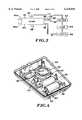
- FIG. 4is a perspective view of the radial DMA and related components
- FIG. 5is a top view of the DMA
- FIG. 6is a side elevation of the DMA
- FIG. 7is a sectional view taken along the line 7--7 in FIG. 5;
- FIG. 8is a chart illustrating a band of selected aerosol particle sizes, superimposed on a plot of filtration efficiency vs. particle size
- FIG. 9is a schematic view of a cylindrical differential mobility analyzer adapted for use in lieu of the radial DMA in an alternative embodiment fit-testing system;
- FIG. 10is a chart superimposing a broad range of particle sizes superimposed on a plot of filtration efficiency vs. particle size
- FIG. 11is a schematic view of an impactor for segregating suspended elements in another alternative embodiment fit-testing system
- FIG. 12is a schematic view of a condensation particle counter for generating element concentration values in the test system
- FIG. 13illustrates a further alternative embodiment respirator testing system employing individual separation and concentration-determining stages
- FIG. 14illustrates another respirator testing system employing alternative particle separation stages in combination with a single particle counting stage.
- FIG. 2a testing system 16 for evaluating a filtration device for leakage, as opposed to particle penetration.
- system 16is used to conduct quantitative fit-tests on filtration devices such as an air purifing respirator 18.
- Respirator 18is from one of several respirator classes, e.g. N95, that exhibit a fractional filtration efficiency that varies with particle size.
- these filterstypically have a minimum efficiency (maximum particle penetration) at some midpoint on the size spectrum, typically 0.1 to 0.3 micrometers. Efficiency increases in either direction from the midpoint.
- aerosolrefers to a suspension of elements (e.g. solid particles or droplets) in a gaseous medium. Atmospheric or ambient air is an example of an aerosol, with air as the gaseous medium supporting typically 3,000-10,000 elements per cubic cm.
- Ambient airfurther is a "polydisperse aerosol", because the particles or other elements vary widely in size across the range illustrated in FIG. 1.
- a “monodisperse aerosol”is comprised of particles at or near a particular diameter.
- System 16is designed to overcome a problem encountered when respirator 18 is tested by sampling a polydisperse aerosol.
- the problemdiscussed in more detail above, is the tendency of aerosol particles or other elements in the low efficiency mid-range to penetrate the respirator's filter, biasing test results toward an inaccurately low fit factor, i.e. indicating a greater degree of leakage than actually occurred.
- system 16includes an aerosol sampling stage 22, an aerosol element separating stage 24, a concentration measuring stage 26 and a processing stage 28.
- Sampling stage 22includes a pair of sampling conduits 30 and 32, typically flexible tubing or hose constructed of a suitable polymer.
- Conduit 30is adapted to draw an aerosol sample from inside of a respirator mask 33 to be tested.
- a test mask of the type to be usedis equipped with a face-piece probe 35 to which an entrance port 34 is coupled.
- An entrance port 36 of conduit 32is positioned proximate the mask but outside of it.
- conduit 32draws an aerosol sample from the atmosphere or environment immediately surrounding the mask under test.
- the testis conducted either under ambient conditions, within a combination of an ambient and a supplemental aerosol, or within an environment which, to the extent practicable, duplicates the working conditions the individual is expected to encounter when wearing the respirator.
- No monodisperse aerosolis generated into the atmosphere about the mask, nor is the test conducted within a chamber or other enclosure for containing a specially generated atmosphere. Accordingly, the aerosol samples drawn into conduits 30 and 32 are virtually certain to be polydisperse.
- each of the aerosol samplesis modified in view of the type of mask being tested.
- Some of the polydisperse suspended elements (usually particles) in the aerosolare selected according to their size or another suitable characteristic, to provide in each case a modified aerosol sample, in which the suspension consists of those particles for which the respirator filter involved is highly efficient. In other words, particles which have an unacceptably high penetration into the filter, typically due to their size, are excluded from the sample.
- the resulting modified samplecan be either a monodisperse aerosol or a polydisperse aerosol. In either event, however, the remaining particulate has a sufficiently low penetration with respect to the filter under test, to justify an assumption that virtually all of such particles found in the respirator sample entered the mask due to leakage.
- FIG. 3illustrates the separation stage in greater detail.
- the samples from conduits 30 and 32are provided alternatively through a selector valve 38 to an inlet 40 of a radial differential mobility analyzer (radial DMA) 42.
- Radial DMA 42has a disk-shaped housing 44 generally symmetrical about a central axis which is not illustrated but which would be vertical in FIG. 3.
- one or more additional inletscan be provided, circumferentially about DMA 42. In such cases, all of the inputs simultaneously receive either the mask sample or the ambient sample.
- the radial DMAutilizes a clean sheath air flow, provided to the DMA at an inlet 46 for eventual merger with the sample flow within the DMA.
- outputs from the DMAinclude a modified sample exit 48 and an excess air exit 50.
- the excess air flowis directed through a filter 52 to a diaphragm pump 54 that governs the sheath flow rate, through another filter 56 and then returned to the DMA through inlet 46. Additional sheath air inlets can be provided.
- FIG. 4illustrates an advantage of using radial DMA 42 for aerosol separation; namely, that the DMA and its components can be packaged into a relatively small container 58 as shown, with filters 52 and 56 side by side.
- Pump 54is situated between the filters and selector valve 38.
- Inlet ports 60 and 62 for the mask sample and ambient sample, respectively,are side by side and upstream of the valve.
- Flexible tubingcouples the components to provide the fluid paths illustrated in FIG. 3.
- a top cover(not shown) fits in a nesting engagement against the container to enclose the components.
- FIGS. 5 and 6show the exterior of radial DMA 42 in greater detail.
- the interior of the DMAis seen in FIG. 7.
- the DMAhas an annular base 64, preferably formed of an electrically insulative material with strength to provide rigidity, e.g. a polymer with a high modulus of elasticity.
- Base 64defines an annular channel 66 for receiving sheath air.
- a porous plastic ring 68is supported along the top of channel 66, and acts as a diffuser to provide a laminar air flow upwardly out of the sheath air channel.
- An electrically conductive plate 70constructed of stainless steel, is supported within a recess at the top of base 64. Plate 70 is electrically coupled to an electrical power source as indicated schematically at V, for example through a pin or threaded member 72 that extends through a top wall 74 of the base.
- Exit 48 for the modified aerosol sampleis formed along the vertical central axis.
- An annular aluminum cover 76is secured to the base, with a sealing ring 78 provided to ensure that the coupling forms a fluid seal.
- the coverdefines a cylindrical upper chamber 80.
- Cover 76further is formed to provide exit 50 for excess air.
- exit 50is formed along the vertical central axis if the radial DMA.
- An annular, arcuate divider 82preferably stainless steel, is disposed between cover 76 and base 64.
- the aerosol sampleenters chamber 80 at the chamber periphery above divider 82, then flows radially inward toward exits 48 and 50 through a small gap (8-30 mils, more preferably about 15 mils) between divider 82 and the cover. At the same time, sheath air flows upwardly from diffluser ring 68, then radially inward toward the exits for merger with the aerosol sample.
- particles suspended in the aerosol sampleare segregated, in that particles within a particular range of electrical mobility are physically separated from particles in the sample outside of that range.
- particles smaller than a certain nominal size, and having a charge opposite that of plate 70are attracted to the plate and do not reach exits 48 and 50.
- larger particlestend to leave the radial DMA through exit port 50.
- Particles close to the nominal size, and having the opposite charge to that of the plateare attracted downward yet reach the center of the radial DMA. Consequently, these particles leave the DMA through exit 48 as part of the modified aerosol sample.
- These latter particlescan be considered monodisperse, because they are confined within a considerably narrower size range than the polydisperse elements of the entering aerosol sample.
- the flow rates of the aerosol sample and the sheath airare controlled to maintain the respective flow rates substantially constant, and more particularly to maintain a desired ratio of sheath air flow to sample aerosol flow.
- the aerosol samplecan be provided to the radial DMA at a rate of about 0.7 liters per minute (1 pm) with sheath air flow less than about 3.01 pm.
- sheath flowis kept sufficiently low to provide a ratio of sheath flow/sample flow of at most about 3:1 and at least about 2:1. More preferably, the ratio is about 2.5:1.
- the sample flow rateis determined at least in part by the particle counter or other measuring device of measuring stage 26 downstream, with the sheath rate adjusted to provide the desired ratio.
- the upper end ratio of 3:1is less than previously preferred sheath/sample flow ratios, typically ranging from 10:1 down to about 4:1.
- the purpose of the lower flow ratio in DMA 42is to broaden the transfer function, i.e. the likelihood that a particle entering the DMA will be segregated and removed by the DMA. This has the net effect of increasing the number of segregated particles, while still operating in a region outside of the particles known to penetrate the filter under test.
- system 16Another distinguishing feature of system 16 is that the polydisperse elements of the aerosol samples are not subjected to a charging device to be electrically charged as they enter the radial DMA. Rather, the aerosol samples are received in the natural state, with a naturally occurring charge distribution. Although the majority of the elements typically are neutral in the natural state, a substantial proportion of the particles are charged, in most cases resulting in a sufficient count for reasonable statistical accuracy, even though the counted elements might represent only 1-2% of the original polydisburse elements.
- FIG. 8graphically illustrates segregation of a polydisperse aerosol sample to select particles based on a nominal diameter of 40 mn, with the full bandwidth 86 of selected particles ranging from about 35 nm to about 50 nm.
- a filtration efficiency plot 84shows that the filter involved has an efficiency of about 92% at the most penetrating particle size, about 160 nm. However, the filtration efficiency is at least 99.9% throughout selected bandwidth 86, and is considerably higher at the low end of the range.
- DMAdifferential mobility analyzer
- An upright cylindrical housing 90receives a sample aerosol through an inlet conduit 92, and receives sheath air through an inlet conduit 94 located radically inwardly of the sampling inlet conduit.
- the aerosol sample inlet conduitalternatively handles the samples taken from inside the respirator mask and proximate but outside the mask. As it flows toward DMA housing 90, the aerosol sample flows through a bipolar charger 96 where the polydisperse elements are charged.
- the aerosol sampleenters the housing radially outwardly of a frusto-conical deflector 98, while the sheath air enters the housing radially inwardly of deflector 98.
- An axially extended charged rod 100attracts elements of the opposite charge (typically positive).
- the outer wall of the housingis grounded.
- a narrow bandwidth of particle or element sizesmay not yield a sufficient particle count to provide a desired level of statistical accuracy.
- FIG. 11schematically illustrates an impactor 116 including a converging nozzle 118 that receives the aerosol sample for a downward flow, ajet exit 120 at the bottom of the nozzle, and an impaction plate 122 spaced apart vertically from the jet exit.
- particles of sufficient inertiaimpact upon the upper surface impaction plate 122.
- Particles not impacting the platei.e. the smaller particles with an inertia at or below a nominal level, proceed to a measurement stage as part of a modified aerosol sample.
- the nominal level of inertiais influenced by a variety of factors, including flow volocity, dimensions of the nozzle and jet exit, and spacing between the jet exit and the impaction plate.
- a filtration efficiency plot 114indicates maximum penetration at a particle size of about 160 mn. Particles or other elements are segregated, based on a nominal diameter of 40 nm, with the shaded area on the graph indicting that all elements having a 40 nm diameter or smaller are retained in the modified aerosol sample. The minimum filtration efficiency within this range, about 99.92%, occurs at the 40 nm size.
- a broader bandwidth of particlesis selected for concentration measurements.
- a particle measuring instrumentthat is sensitive to smaller diameter particles, e.g., a condensation particle counter.
- Other devices suitable for segregating particles by inertiainclude virtual impactors, cyclones, horizontal elutriators, and centrifugal separators.
- the number of elements in the measured samplesit may be desirable to supplement the naturally occurring aerosol with a generated polydisperse aerosol.
- a simple self-contained compressor and atomizeras a polydisperse aerosol generator, utilizing a 2% salt solution.
- This generatorproduces an additional 3,000 to 5,000 particles/cc which combine with the naturally occurring ambient aerosol near the mask.
- the additional particlesincrease the number of elements segregated from the sampled aerosol, and increase the statistical validity of the measurements.
- the operating principleis the same: namely, to segregate a portion of a polydisperse aerosol to produce a modified aerosol in which virtually all of the suspended particles are within a range known to have an acceptably low penetration rate for the filter under test. Because any leakage generally is independent of the particle size involved, the fit factors are no less reliable for the fact that they are based on modified aerosol samples with more limited bandwidths of particle sizes.
- the output of separating stage 24is provided to concentration measuring stage 26.
- the outputincludes, alternatively, a first modified aerosol sample based on the original sample taken from within respirator mask 33, and a second modified sample reflecting the ambient sample taken near the respirator.
- the modified aerosol samplesare provided as the alternative outputs of radial DMA 42, to an inlet 124 of a condensation particle counter 126 (FIG. 12), which can be similar to the device described in U.S. Pat. No. 4,790,650 (Keady).
- the modified aerosol sample entering inlet 124proceeds through a saturation zone 128, where butyl alcohol or another volatile liquid is continually evaporated into the gas stream.
- the gas stream, substantially saturated,proceeds into a condensation zone 130, where the aerosol is cooled sufficiently to cause the volatile liquid to condense onto the suspended particles, in effect "growing" each particle to a larger effective size for easier detection.
- the enlarged particlesproceed to an optical detection zone 132, where individual particles pass through and momentarily interrupt a laser beam, thus to generate a particle recognition signal and add to an accumulated particle count.
- the accumulated particle countis a concentration value that indicates the concentration of particles suspended in the aerosol.
- the output of condensation particle counter 126includes first and second concentration values, associated with the first and second modified aerosol samples, respectively.
- condensation particle counter 126is the preferred instrument at the concentration measuring stage.
- An electrometeris a suitable alternative under these circumstances.
- other aerosol separation devicese.g., virtual impactors, generate size-selected aerosols with suspended particles larger than 0.5 microns in diameter.
- an optical particle counter or photometermay be used to generate concentration values.
- measurement of scattered light intensitiescan be used in lieu of particle counting.
- the respective concentration valuesare provided to processing stage 28, where they are compared to generate a ratio of the ambient concentration value to the mask concentration value, i.e. the fit factor.
- FIG. 13illustrates an alternative embodiment system 134 with independent paths for simultaneously generating ambient and mask concentration values.
- a polydisperse aerosol sample from inside a respirator 136is provided to a radial DMA or other separator 138, which in turn provides a modified aerosol sample to a condensation particle counter or other measuring instrument 140, which provides as its output a concentration value reflecting conditions inside the respirator mask.
- an ambient sampleis provided to a separator 142, which provides a modified aerosol sample to a measuring instrument 144, the output of which is a concentration value indicating ambient conditions near the respirator.
- FIG. 14illustrates a further alternative embodiment system 146 in which respective ambient and respirator aerosol samples are provided, alternatively, either to a radial DMA 148 or an impactor 150 at the separating stage, and then from the separating stage to a condensation particle counter 152 which provides the respective concentration values to a processor 154.
- the primary advantage of system 146is flexibility, in that the segregation of suspended particles can be based on a narrow bandwidth of sizes using the DMA, or based on a larger bandwidth by switching to impactor 150, when DMA 148 is found to yield an insufficient number of suspended particles for a desired level of statistical accuracy.
- an aerosol generator 156can provide a supplemental aerosol for measurement in combination with the ambient aerosol.
- a respiratorcan be fit-tested based on sampling polydisperse aerosols under ambient conditions, even when the respirator filter has an unacceptably high penetration rate for certain sizes of particles. Suspended particles in the aerosol samples are segregated, to retain in modified aerosol samples only particles for which the tested filter has a high filtration efficiency. The particles having high tendencies to penetrate the filter are physically removed, and thus are prevented from contaminating results intended to reflect leakage alone. There is no need for devices that generate prescribed artificial atmospheres, and no need for enclosures to confine individuals within such atmospheres during testing. In addition to considerably reducing the cost of fit-testing, the system affords an individual more freedom of movement to perform tasks and movements anticipated under normal working conditions.
Landscapes
- Health & Medical Sciences (AREA)
- Pulmonology (AREA)
- General Health & Medical Sciences (AREA)
- Business, Economics & Management (AREA)
- Emergency Management (AREA)
- Respiratory Apparatuses And Protective Means (AREA)
Abstract
Description
Claims (40)
Priority Applications (1)
| Application Number | Priority Date | Filing Date | Title |
|---|---|---|---|
| US08/939,995US6125845A (en) | 1997-08-29 | 1997-08-29 | Respirator fit-testing with size selected aerosol |
Applications Claiming Priority (1)
| Application Number | Priority Date | Filing Date | Title |
|---|---|---|---|
| US08/939,995US6125845A (en) | 1997-08-29 | 1997-08-29 | Respirator fit-testing with size selected aerosol |
Publications (1)
| Publication Number | Publication Date |
|---|---|
| US6125845Atrue US6125845A (en) | 2000-10-03 |
Family
ID=25474053
Family Applications (1)
| Application Number | Title | Priority Date | Filing Date |
|---|---|---|---|
| US08/939,995Expired - LifetimeUS6125845A (en) | 1997-08-29 | 1997-08-29 | Respirator fit-testing with size selected aerosol |
Country Status (1)
| Country | Link |
|---|---|
| US (1) | US6125845A (en) |
Cited By (33)
| Publication number | Priority date | Publication date | Assignee | Title |
|---|---|---|---|---|
| US6435009B1 (en)* | 1998-06-01 | 2002-08-20 | Hamilton Associates, Inc. | Portable multi-function system for testing protective devices |
| US20020124664A1 (en)* | 1998-11-13 | 2002-09-12 | Mesosystems Technology, Inc. | Robust system for screening mail for biological agents |
| US20040232052A1 (en)* | 1998-11-13 | 2004-11-25 | Call Charles John | Methods and devices for continuous sampling of airborne particles using a regenerative surface |
| US20050190058A1 (en)* | 2004-03-01 | 2005-09-01 | Call Charles J. | Networks with sensors for air safety and security |
| US6955170B1 (en)* | 2000-10-27 | 2005-10-18 | 3M Innovative Properties Company | Automated respirator fit testing method and system |
| US7036502B2 (en) | 2002-04-08 | 2006-05-02 | Joseph Manne | Air curtain device |
| US20060257287A1 (en)* | 1998-11-13 | 2006-11-16 | Call Charles J | Robust system for screening enclosed spaces for biological agents |
| US20070048186A1 (en)* | 1998-11-13 | 2007-03-01 | Mesosystems Technology, Inc. | Removing surface deposits of concentrated collected particles |
| WO2007031772A1 (en)* | 2005-09-15 | 2007-03-22 | The Secretary Of State For Defence | Apparatus and methods for dilution |
| US20090078064A1 (en)* | 2007-08-06 | 2009-03-26 | Abraham Oommen | Instrument for simultaneous analysis of multiple samples using multiple differential mobility analyzers |
| US7591980B2 (en) | 2004-03-01 | 2009-09-22 | Mesosystems Technology, Inc. | Biological alarm |
| US7614280B1 (en)* | 2006-03-06 | 2009-11-10 | The United States Of America As Represented By The Secretary Of The Army | Quantitative fit test system and method for assessing respirator biological fit factors |
| US20100212670A1 (en)* | 2009-02-20 | 2010-08-26 | Amighi Amir H | Ported Respirator Mask for In Situ Respirator Testing and Method of Use |
| US7799567B1 (en) | 1999-03-10 | 2010-09-21 | Mesosystems Technology, Inc. | Air sampler based on virtual impaction and actual impaction |
| US20110138884A1 (en)* | 2009-12-11 | 2011-06-16 | Eric Hanson | Portable multi-function system for testing protective devices |
| US20110203044A1 (en)* | 2004-07-12 | 2011-08-25 | Izen Co., Ltd. | Spray nozzle structure for a bidet having an enema function |
| US8047053B2 (en) | 2007-05-09 | 2011-11-01 | Icx Technologies, Inc. | Mail parcel screening using multiple detection technologies |
| US8173431B1 (en) | 1998-11-13 | 2012-05-08 | Flir Systems, Inc. | Mail screening to detect mail contaminated with biological harmful substances |
| US8192523B1 (en) | 2008-02-22 | 2012-06-05 | Tsi Incorporated | Device and method for separating and increasing the concentration of charged particles in a sampled aerosol |
| US8243274B2 (en) | 2009-03-09 | 2012-08-14 | Flir Systems, Inc. | Portable diesel particulate monitor |
| US8573199B2 (en) | 2010-04-30 | 2013-11-05 | Centers For Disease Control And Prevention | Ultrasonic in situ respiratory mask testing process and mask |
| US9121844B1 (en)* | 2008-09-09 | 2015-09-01 | Sociedad Europea de Analisis Diferencial de Movilidad | Method to analyze and classify persons and organisms based on odor patterns from released vapors |
| WO2020092821A3 (en)* | 2018-11-01 | 2020-07-30 | Bjorquist Dan | In situ respirator fit testing |
| US11213703B2 (en) | 2018-03-21 | 2022-01-04 | AccuTec-IHS, Inc. | Tool and method for instertion of a probe for fit-testing filtering facepieces |
| US11358014B2 (en) | 2016-01-08 | 2022-06-14 | Tsi, Incorporated | Wearable mask fit monitor |
| US11474020B2 (en) | 2017-09-01 | 2022-10-18 | 3M Innovative Properties Company | Sensing element for respirator |
| WO2022235472A1 (en) | 2021-05-06 | 2022-11-10 | 3M Innovative Properties Company | Systems and methods for improved respiratory protection devices |
| US11534632B2 (en) | 2017-09-01 | 2022-12-27 | 3M Innovative Properties Company | Fit-test method for respirator with sensing system |
| US11686660B2 (en) | 2018-06-07 | 2023-06-27 | Sensors, Inc. | Particle concentration analyzing system and method |
| US11793422B2 (en) | 2017-09-01 | 2023-10-24 | 3M Innovative Properties Company | Sensing system for respirator |
| US11918837B2 (en) | 2017-09-01 | 2024-03-05 | 3M Innovative Properties Company | Fit-test method for respirator with sensing system |
| WO2025125970A1 (en) | 2023-12-15 | 2025-06-19 | 3M Innovative Properties Company | Respiratory protection devices and methods of manufacturing the same |
| WO2025202974A1 (en) | 2024-03-29 | 2025-10-02 | 3M Innovative Properties Company | Respirators, respirator materials and methods of manufacturing the same |
Citations (14)
| Publication number | Priority date | Publication date | Assignee | Title |
|---|---|---|---|---|
| US31952A (en)* | 1861-04-09 | Seeding-machine | ||
| US3806248A (en)* | 1973-02-21 | 1974-04-23 | Atomic Energy Commission | Continuous flow condensation nuclei counter |
| GB1422188A (en)* | 1972-06-21 | 1976-01-28 | Commissariat Energie Atomique | Device for counting particles in an aerosol |
| US4055075A (en)* | 1976-04-08 | 1977-10-25 | Flanders Filters, Inc. | Method and apparatus for the leak testing of filters |
| US4324568A (en)* | 1980-08-11 | 1982-04-13 | Flanders Filters, Inc. | Method and apparatus for the leak testing of filters |
| US4402214A (en)* | 1981-04-08 | 1983-09-06 | Facet Enterprises, Inc. | Filter element test method and apparatus |
| US4494403A (en)* | 1982-07-14 | 1985-01-22 | Flanders Filters, Inc. | Filter testing apparatus and method |
| US4515007A (en)* | 1983-01-04 | 1985-05-07 | The United States Of America As Represented By The United States Department Of Energy | Method of and apparatus for testing the integrity of filters |
| USRE31952E (en) | 1980-08-11 | 1985-07-23 | Flanders Filters, Inc. | Method and apparatus for the leak testing of filters |
| US4914957A (en)* | 1988-04-15 | 1990-04-10 | Westinghouse Electric Corp. | Leak test adaptor apparatus for facilitating leak testing face mask respirators |
| US5117190A (en)* | 1989-06-23 | 1992-05-26 | Commissariat A L'energie Atomique | Electrostatic detector of aerosol particles |
| US5299448A (en)* | 1993-03-05 | 1994-04-05 | Cabot Safety Corporation | Positive pressure test apparatus for facepiece respirator |
| US5428220A (en)* | 1993-11-29 | 1995-06-27 | The United States Of America As Represented By The Secretary Of Commerce | Aerosol mass spectrometer and method of classifying aerosol particles according to specific mass |
| US5596136A (en)* | 1995-07-27 | 1997-01-21 | California Institute Of Technology | Radial differential mobility analyzer |
- 1997
- 1997-08-29USUS08/939,995patent/US6125845A/ennot_activeExpired - Lifetime
Patent Citations (15)
| Publication number | Priority date | Publication date | Assignee | Title |
|---|---|---|---|---|
| US31952A (en)* | 1861-04-09 | Seeding-machine | ||
| GB1422188A (en)* | 1972-06-21 | 1976-01-28 | Commissariat Energie Atomique | Device for counting particles in an aerosol |
| US3806248A (en)* | 1973-02-21 | 1974-04-23 | Atomic Energy Commission | Continuous flow condensation nuclei counter |
| US4055075A (en)* | 1976-04-08 | 1977-10-25 | Flanders Filters, Inc. | Method and apparatus for the leak testing of filters |
| USRE31952E (en) | 1980-08-11 | 1985-07-23 | Flanders Filters, Inc. | Method and apparatus for the leak testing of filters |
| US4324568A (en)* | 1980-08-11 | 1982-04-13 | Flanders Filters, Inc. | Method and apparatus for the leak testing of filters |
| US4402214A (en)* | 1981-04-08 | 1983-09-06 | Facet Enterprises, Inc. | Filter element test method and apparatus |
| US4494403A (en)* | 1982-07-14 | 1985-01-22 | Flanders Filters, Inc. | Filter testing apparatus and method |
| US4515007A (en)* | 1983-01-04 | 1985-05-07 | The United States Of America As Represented By The United States Department Of Energy | Method of and apparatus for testing the integrity of filters |
| US4914957A (en)* | 1988-04-15 | 1990-04-10 | Westinghouse Electric Corp. | Leak test adaptor apparatus for facilitating leak testing face mask respirators |
| US5117190A (en)* | 1989-06-23 | 1992-05-26 | Commissariat A L'energie Atomique | Electrostatic detector of aerosol particles |
| US5299448A (en)* | 1993-03-05 | 1994-04-05 | Cabot Safety Corporation | Positive pressure test apparatus for facepiece respirator |
| US5428220A (en)* | 1993-11-29 | 1995-06-27 | The United States Of America As Represented By The Secretary Of Commerce | Aerosol mass spectrometer and method of classifying aerosol particles according to specific mass |
| US5596136A (en)* | 1995-07-27 | 1997-01-21 | California Institute Of Technology | Radial differential mobility analyzer |
| US5606112A (en)* | 1995-07-27 | 1997-02-25 | California Institute Of Technology | Radial differential mobility analyzer |
Non-Patent Citations (16)
| Title |
|---|
| "A Quantitative Fit Test for Dust/Mist Respirators: Part II", Danisch, et al., Appl Occup. Environ. Hyg., 7(4) p. 241-245, Apr. 1992. |
| "Aerosol Penetration through Filtering Facepieces and Respirator Cartridges", Chen, et al., Am. Ind. Hyg. Assoc. Journal 53(9): 566-574 (1992). |
| "Fit Test for Filtering Facepieces: Search for a Low Cost Quantitative Method", Myojo, et al., Am. Ind. Hyg. Assoc. Journal (55(9): 797-805 (1994). |
| "New Methods for Quantitative Respirator Fit Testing with Aerosols", Willeke, et al., Am. Ind. Hyg. Assoc. Journal, pp. 121-125, Feb. 1981. |
| "Numerical Modeling of the Performance of the Differential Mobility Analyzer for Nanometer Aerosol Measurements", Chen, et al., J. Aerosol Sci., vol. 26, Suppl 1. Pp. S141-S142, 1995. |
| "Quantitative Fit Testing Techniques and Regulations for Tight Fitting Respirators: Current Methods Measuring Aerosol or Air Leakage, and New Developments", Hee Han, et al., American Industry Hygiene Association Journal 58:219-228 (1997). |
| "Radial Differential Mobility Analyzer", Zhang, et al., Aerosol Science and Technology, 23: 357-372 (1995). |
| "Validation of a Quantitative Fir Test for Dust/Fume/Mist Respirators: Part I", Iverson, et al., Appl Occup. Environ. Hyg. 7(3) Mar. 1992. |
| A Quantitative Fit Test for Dust/Mist Respirators: Part II , Danisch, et al., Appl Occup. Environ. Hyg. , 7(4) p. 241 245, Apr. 1992.* |
| Aerosol Penetration through Filtering Facepieces and Respirator Cartridges , Chen, et al., Am. Ind. Hyg. Assoc. Journal 53(9): 566 574 (1992).* |
| Fit Test for Filtering Facepieces: Search for a Low Cost Quantitative Method , Myojo, et al., Am. Ind. Hyg. Assoc. Journal (55(9): 797 805 (1994).* |
| New Methods for Quantitative Respirator Fit Testing with Aerosols , Willeke, et al., Am. Ind. Hyg. Assoc. Journal , pp. 121 125, Feb. 1981.* |
| Numerical Modeling of the Performance of the Differential Mobility Analyzer for Nanometer Aerosol Measurements , Chen, et al., J. Aerosol Sci. , vol. 26, Suppl 1. Pp. S141 S142, 1995.* |
| Quantitative Fit Testing Techniques and Regulations for Tight Fitting Respirators: Current Methods Measuring Aerosol or Air Leakage, and New Developments , Hee Han, et al., American Industry Hygiene Association Journal 58:219 228 (1997).* |
| Radial Differential Mobility Analyzer , Zhang, et al., Aerosol Science and Technology , 23: 357 372 (1995).* |
| Validation of a Quantitative Fir Test for Dust/Fume/Mist Respirators: Part I , Iverson, et al., Appl Occup. Environ. Hyg. 7(3) Mar. 1992.* |
Cited By (52)
| Publication number | Priority date | Publication date | Assignee | Title |
|---|---|---|---|---|
| US6435009B1 (en)* | 1998-06-01 | 2002-08-20 | Hamilton Associates, Inc. | Portable multi-function system for testing protective devices |
| US7343783B2 (en) | 1998-06-01 | 2008-03-18 | Hamilton Associates, Inc. | Portable multi-function system for testing protective devices |
| US20070062259A1 (en)* | 1998-06-01 | 2007-03-22 | Tilley Greg A | Portable multi-function system for testing protective devices |
| US6887710B2 (en)* | 1998-11-13 | 2005-05-03 | Mesosystems Technology, Inc. | Robust system for screening mail for biological agents |
| US8173431B1 (en) | 1998-11-13 | 2012-05-08 | Flir Systems, Inc. | Mail screening to detect mail contaminated with biological harmful substances |
| US20060257287A1 (en)* | 1998-11-13 | 2006-11-16 | Call Charles J | Robust system for screening enclosed spaces for biological agents |
| US20070048186A1 (en)* | 1998-11-13 | 2007-03-01 | Mesosystems Technology, Inc. | Removing surface deposits of concentrated collected particles |
| US20040232052A1 (en)* | 1998-11-13 | 2004-11-25 | Call Charles John | Methods and devices for continuous sampling of airborne particles using a regenerative surface |
| US7759123B2 (en) | 1998-11-13 | 2010-07-20 | Mesosystems Technology, Inc. | Removing surface deposits of concentrated collected particles |
| US20020124664A1 (en)* | 1998-11-13 | 2002-09-12 | Mesosystems Technology, Inc. | Robust system for screening mail for biological agents |
| US7578973B2 (en) | 1998-11-13 | 2009-08-25 | Mesosystems Technology, Inc. | Devices for continuous sampling of airborne particles using a regenerative surface |
| US20100242632A1 (en)* | 1999-03-10 | 2010-09-30 | Mesosystems Technology, Inc. | Air sampler based on virtual impaction and actual impaction |
| US7799567B1 (en) | 1999-03-10 | 2010-09-21 | Mesosystems Technology, Inc. | Air sampler based on virtual impaction and actual impaction |
| US6955170B1 (en)* | 2000-10-27 | 2005-10-18 | 3M Innovative Properties Company | Automated respirator fit testing method and system |
| US7036502B2 (en) | 2002-04-08 | 2006-05-02 | Joseph Manne | Air curtain device |
| US7591980B2 (en) | 2004-03-01 | 2009-09-22 | Mesosystems Technology, Inc. | Biological alarm |
| US7265669B2 (en) | 2004-03-01 | 2007-09-04 | Mesosystems Technology, Inc. | Networks with sensors for air safety and security |
| US20050190058A1 (en)* | 2004-03-01 | 2005-09-01 | Call Charles J. | Networks with sensors for air safety and security |
| US20110203044A1 (en)* | 2004-07-12 | 2011-08-25 | Izen Co., Ltd. | Spray nozzle structure for a bidet having an enema function |
| US20080202196A1 (en)* | 2005-09-15 | 2008-08-28 | The Secretary Of State For Defence | Apparatus and Methods For Dilution |
| GB2445683A (en)* | 2005-09-15 | 2008-07-16 | Secr Defence | Apparatus and methods for dilution |
| WO2007031772A1 (en)* | 2005-09-15 | 2007-03-22 | The Secretary Of State For Defence | Apparatus and methods for dilution |
| GB2445683B (en)* | 2005-09-15 | 2010-10-13 | Secr Defence | Apparatus and methods for dilution |
| US7913535B2 (en) | 2005-09-15 | 2011-03-29 | The Secretary Of State For Defence In Her Britannic Majesty's Government Of The United Kingdom Of Great Britain And Northern Ireland | Apparatus and methods for dilution |
| US7614280B1 (en)* | 2006-03-06 | 2009-11-10 | The United States Of America As Represented By The Secretary Of The Army | Quantitative fit test system and method for assessing respirator biological fit factors |
| US8151630B1 (en)* | 2006-03-06 | 2012-04-10 | The United States Of America As Represented By The Secretary Of The Army | Quantitative fit test system and method for assessing respirator biological fit factors |
| US8047053B2 (en) | 2007-05-09 | 2011-11-01 | Icx Technologies, Inc. | Mail parcel screening using multiple detection technologies |
| US20090078064A1 (en)* | 2007-08-06 | 2009-03-26 | Abraham Oommen | Instrument for simultaneous analysis of multiple samples using multiple differential mobility analyzers |
| US8192523B1 (en) | 2008-02-22 | 2012-06-05 | Tsi Incorporated | Device and method for separating and increasing the concentration of charged particles in a sampled aerosol |
| US9121844B1 (en)* | 2008-09-09 | 2015-09-01 | Sociedad Europea de Analisis Diferencial de Movilidad | Method to analyze and classify persons and organisms based on odor patterns from released vapors |
| US20100212670A1 (en)* | 2009-02-20 | 2010-08-26 | Amighi Amir H | Ported Respirator Mask for In Situ Respirator Testing and Method of Use |
| US8243274B2 (en) | 2009-03-09 | 2012-08-14 | Flir Systems, Inc. | Portable diesel particulate monitor |
| US8196454B2 (en)* | 2009-12-11 | 2012-06-12 | Hamilton Associates, Inc. | Portable multi-function system for testing protective devices |
| US20110138884A1 (en)* | 2009-12-11 | 2011-06-16 | Eric Hanson | Portable multi-function system for testing protective devices |
| US8573199B2 (en) | 2010-04-30 | 2013-11-05 | Centers For Disease Control And Prevention | Ultrasonic in situ respiratory mask testing process and mask |
| US11358014B2 (en) | 2016-01-08 | 2022-06-14 | Tsi, Incorporated | Wearable mask fit monitor |
| US11918837B2 (en) | 2017-09-01 | 2024-03-05 | 3M Innovative Properties Company | Fit-test method for respirator with sensing system |
| US11793422B2 (en) | 2017-09-01 | 2023-10-24 | 3M Innovative Properties Company | Sensing system for respirator |
| US11534632B2 (en) | 2017-09-01 | 2022-12-27 | 3M Innovative Properties Company | Fit-test method for respirator with sensing system |
| US11474020B2 (en) | 2017-09-01 | 2022-10-18 | 3M Innovative Properties Company | Sensing element for respirator |
| US11213703B2 (en) | 2018-03-21 | 2022-01-04 | AccuTec-IHS, Inc. | Tool and method for instertion of a probe for fit-testing filtering facepieces |
| US11686660B2 (en) | 2018-06-07 | 2023-06-27 | Sensors, Inc. | Particle concentration analyzing system and method |
| US11305138B2 (en) | 2018-11-01 | 2022-04-19 | Tsi Incorporated | In situ respirator fit testing |
| JP2022502674A (en)* | 2018-11-01 | 2022-01-11 | ティーエスアイ インコーポレイテッド | In situ Respirator Fit Test |
| KR102332827B1 (en) | 2018-11-01 | 2021-12-01 | 티에스아이 인코포레이티드 | In situ respiratory fitting testing |
| EP3873625A4 (en)* | 2018-11-01 | 2023-07-05 | Aerosol Dynamics Inc. | IN SITU VENTILATOR PASSPORT CHECK |
| KR20210102225A (en)* | 2018-11-01 | 2021-08-19 | 티에스아이 인코포레이티드 | In situ respiratory fitting testing |
| WO2020092821A3 (en)* | 2018-11-01 | 2020-07-30 | Bjorquist Dan | In situ respirator fit testing |
| WO2022235472A1 (en) | 2021-05-06 | 2022-11-10 | 3M Innovative Properties Company | Systems and methods for improved respiratory protection devices |
| US12419369B2 (en) | 2021-05-06 | 2025-09-23 | 3M Innovative Properties Company | Systems and methods for improved respiratory protection devices |
| WO2025125970A1 (en) | 2023-12-15 | 2025-06-19 | 3M Innovative Properties Company | Respiratory protection devices and methods of manufacturing the same |
| WO2025202974A1 (en) | 2024-03-29 | 2025-10-02 | 3M Innovative Properties Company | Respirators, respirator materials and methods of manufacturing the same |
Similar Documents
| Publication | Publication Date | Title |
|---|---|---|
| US6125845A (en) | Respirator fit-testing with size selected aerosol | |
| US7614280B1 (en) | Quantitative fit test system and method for assessing respirator biological fit factors | |
| US8192523B1 (en) | Device and method for separating and increasing the concentration of charged particles in a sampled aerosol | |
| US5498271A (en) | Diesel particle virtual impactor sampler | |
| May | Multistage liquid impinger | |
| US9891154B2 (en) | System and method for converting optical diameters of aerosol particles to mobility and aerodynamic diameters | |
| US9718017B2 (en) | Multi-filter chemical speciation sampler and virtual impaction particle separation inlet therefore | |
| US9506843B2 (en) | Personal nanoparticle respiratory depositions sampler and methods of using the same | |
| US6532797B1 (en) | Barrier test apparatus and method | |
| US5072626A (en) | Measurement of ultrafine particle size distributions | |
| Willeke et al. | New methods for quantitative respirator fit testing with aerosols | |
| US20080196514A1 (en) | Inhalable Sampler | |
| US6170342B1 (en) | Spiral sampler | |
| Lee et al. | Development of a new method for measuring the protection provided by respirators against dust and microorganisms | |
| Lidén | Performance parameters for assessing the acceptability of aerosol sampling equipment | |
| Brosseau et al. | Particle size distribution of automobile paint sprays | |
| Chen et al. | Laboratory performance comparison of respirable samplers | |
| MARSH | Evaluation of saccharin qualitative fitting test for respirators | |
| Baron | Aerosol Photometers for respirable dust measurements | |
| Maynard et al. | Aerosols in the industrial environment | |
| Kolesar et al. | Comparison of respirator protection factors measured by two quantitative fit test methods | |
| Hofacre et al. | Evaluation of the Effect of Particle Size and Particle Sensing Instruments on the Measurement of Mask Protection Factors | |
| Myojo et al. | Comparative study of challenge aerosols for performance test for dust respirators | |
| Langmead et al. | The Personal Centripeter—A Particle Size-Selective Personal Air Sampler | |
| FABRIES et al. | A compact high-flowrate respirable dust sampler: the CPM3 |
Legal Events
| Date | Code | Title | Description |
|---|---|---|---|
| AS | Assignment | Owner name:TSI INCORPORATED, MINNESOTA Free format text:LETTERS PATENT OF AMALGAMATION;ASSIGNORS:HALVORSEN, THOMAS G.;MCDONALD, PATRICIA B. KEADY;REEL/FRAME:009072/0056 Effective date:19980220 | |
| AS | Assignment | Owner name:U.S. BANK NATIONAL ASSOCIATION, MINNESOTA Free format text:SECURITY INTEREST;ASSIGNOR:TSI INCORPORATED;REEL/FRAME:010909/0205 Effective date:20000503 | |
| STCF | Information on status: patent grant | Free format text:PATENTED CASE | |
| FPAY | Fee payment | Year of fee payment:4 | |
| FPAY | Fee payment | Year of fee payment:8 | |
| FPAY | Fee payment | Year of fee payment:12 | |
| AS | Assignment | Owner name:TSI INCORPORATED, MINNESOTA Free format text:RELEASE BY SECURED PARTY;ASSIGNOR:US BANK NATIONAL ASSOCIATION;REEL/FRAME:028453/0189 Effective date:20120620 | |
| AS | Assignment | Owner name:PNC BANK, NATIONAL ASSOCIATION, PENNSYLVANIA Free format text:SECURITY AGREEMENT;ASSIGNORS:TSI INCORPORATED;ENVIRONMENTAL SYSTEMS CORPORATION;DICKEY-JOHN CORPORATION;REEL/FRAME:029169/0775 Effective date:20120620 |