US6125299A - AED with force sensor - Google Patents
AED with force sensorDownload PDFInfo
- Publication number
- US6125299A US6125299AUS09/182,831US18283198AUS6125299AUS 6125299 AUS6125299 AUS 6125299AUS 18283198 AUS18283198 AUS 18283198AUS 6125299 AUS6125299 AUS 6125299A
- Authority
- US
- United States
- Prior art keywords
- force
- aed
- force sensor
- rescuer
- victim
- Prior art date
- Legal status (The legal status is an assumption and is not a legal conclusion. Google has not performed a legal analysis and makes no representation as to the accuracy of the status listed.)
- Ceased
Links
- 238000004891communicationMethods0.000claimsabstractdescription31
- 210000001562sternumAnatomy0.000claimsabstractdescription19
- 238000002680cardiopulmonary resuscitationMethods0.000claimsabstractdescription16
- 230000000694effectsEffects0.000claimsabstractdescription12
- 238000000034methodMethods0.000claimsabstractdescription9
- 239000004020conductorSubstances0.000claimsdescription7
- 230000005540biological transmissionEffects0.000claims4
- 238000001125extrusionMethods0.000claims2
- 239000011888foilSubstances0.000claims1
- 239000000758substrateSubstances0.000description36
- 210000000038chestAnatomy0.000description31
- 238000007906compressionMethods0.000description24
- 230000006835compressionEffects0.000description24
- 239000000017hydrogelSubstances0.000description8
- 239000000463materialSubstances0.000description8
- 230000001070adhesive effectEffects0.000description7
- 239000000853adhesiveSubstances0.000description6
- WABPQHHGFIMREM-UHFFFAOYSA-Nlead(0)Chemical compound[Pb]WABPQHHGFIMREM-UHFFFAOYSA-N0.000description6
- 229920000728polyesterPolymers0.000description5
- 208000010496Heart ArrestDiseases0.000description4
- 229960003965antiepilepticsDrugs0.000description4
- 230000035939shockEffects0.000description4
- 238000010586diagramMethods0.000description3
- 230000006870functionEffects0.000description3
- 238000010248power generationMethods0.000description3
- 230000004044responseEffects0.000description3
- RYGMFSIKBFXOCR-UHFFFAOYSA-NCopperChemical compound[Cu]RYGMFSIKBFXOCR-UHFFFAOYSA-N0.000description2
- PXHVJJICTQNCMI-UHFFFAOYSA-NNickelChemical compound[Ni]PXHVJJICTQNCMI-UHFFFAOYSA-N0.000description2
- 239000004820Pressure-sensitive adhesiveSubstances0.000description2
- BQCADISMDOOEFD-UHFFFAOYSA-NSilverChemical compound[Ag]BQCADISMDOOEFD-UHFFFAOYSA-N0.000description2
- 229920006311Urethane elastomerPolymers0.000description2
- QVGXLLKOCUKJST-UHFFFAOYSA-Natomic oxygenChemical compound[O]QVGXLLKOCUKJST-UHFFFAOYSA-N0.000description2
- 239000008280bloodSubstances0.000description2
- 210000004369bloodAnatomy0.000description2
- 230000017531blood circulationEffects0.000description2
- 239000003990capacitorSubstances0.000description2
- 230000000747cardiac effectEffects0.000description2
- 238000010276constructionMethods0.000description2
- 239000011889copper foilSubstances0.000description2
- 229920001821foam rubberPolymers0.000description2
- 238000012423maintenanceMethods0.000description2
- 229910052760oxygenInorganic materials0.000description2
- 239000001301oxygenSubstances0.000description2
- 239000002985plastic filmSubstances0.000description2
- 229920006255plastic filmPolymers0.000description2
- 239000004417polycarbonateSubstances0.000description2
- 229920000515polycarbonatePolymers0.000description2
- -1polyethylenePolymers0.000description2
- 229920000915polyvinyl chloridePolymers0.000description2
- 230000029058respiratory gaseous exchangeEffects0.000description2
- 239000004065semiconductorSubstances0.000description2
- 229920002379silicone rubberPolymers0.000description2
- 239000004945silicone rubberSubstances0.000description2
- 229910052709silverInorganic materials0.000description2
- 239000004332silverSubstances0.000description2
- 238000012360testing methodMethods0.000description2
- 230000000007visual effectEffects0.000description2
- 239000004698PolyethyleneSubstances0.000description1
- 239000004743PolypropyleneSubstances0.000description1
- 238000010009beatingMethods0.000description1
- 230000003247decreasing effectEffects0.000description1
- 238000001514detection methodMethods0.000description1
- 238000007907direct compressionMethods0.000description1
- 239000006260foamSubstances0.000description1
- 210000004072lungAnatomy0.000description1
- 239000007769metal materialSubstances0.000description1
- 239000012811non-conductive materialSubstances0.000description1
- 230000000737periodic effectEffects0.000description1
- 229920000573polyethylenePolymers0.000description1
- 229920001155polypropylenePolymers0.000description1
- 230000033764rhythmic processEffects0.000description1
- 238000005476solderingMethods0.000description1
- 239000007787solidSubstances0.000description1
- 238000012546transferMethods0.000description1
- 230000002861ventricularEffects0.000description1
- 208000003663ventricular fibrillationDiseases0.000description1
- 206010047302ventricular tachycardiaDiseases0.000description1
Images


Classifications
- A—HUMAN NECESSITIES
- A61—MEDICAL OR VETERINARY SCIENCE; HYGIENE
- A61N—ELECTROTHERAPY; MAGNETOTHERAPY; RADIATION THERAPY; ULTRASOUND THERAPY
- A61N1/00—Electrotherapy; Circuits therefor
- A61N1/18—Applying electric currents by contact electrodes
- A61N1/32—Applying electric currents by contact electrodes alternating or intermittent currents
- A61N1/38—Applying electric currents by contact electrodes alternating or intermittent currents for producing shock effects
- A61N1/39—Heart defibrillators
- A61N1/3925—Monitoring; Protecting
- A—HUMAN NECESSITIES
- A61—MEDICAL OR VETERINARY SCIENCE; HYGIENE
- A61H—PHYSICAL THERAPY APPARATUS, e.g. DEVICES FOR LOCATING OR STIMULATING REFLEX POINTS IN THE BODY; ARTIFICIAL RESPIRATION; MASSAGE; BATHING DEVICES FOR SPECIAL THERAPEUTIC OR HYGIENIC PURPOSES OR SPECIFIC PARTS OF THE BODY
- A61H31/00—Artificial respiration by a force applied to the chest; Heart stimulation, e.g. heart massage
- A61H31/004—Heart stimulation
- A61H31/007—Manual driven
- A—HUMAN NECESSITIES
- A61—MEDICAL OR VETERINARY SCIENCE; HYGIENE
- A61H—PHYSICAL THERAPY APPARATUS, e.g. DEVICES FOR LOCATING OR STIMULATING REFLEX POINTS IN THE BODY; ARTIFICIAL RESPIRATION; MASSAGE; BATHING DEVICES FOR SPECIAL THERAPEUTIC OR HYGIENIC PURPOSES OR SPECIFIC PARTS OF THE BODY
- A61H2201/00—Characteristics of apparatus not provided for in the preceding codes
- A61H2201/50—Control means thereof
- A61H2201/5007—Control means thereof computer controlled
- A—HUMAN NECESSITIES
- A61—MEDICAL OR VETERINARY SCIENCE; HYGIENE
- A61H—PHYSICAL THERAPY APPARATUS, e.g. DEVICES FOR LOCATING OR STIMULATING REFLEX POINTS IN THE BODY; ARTIFICIAL RESPIRATION; MASSAGE; BATHING DEVICES FOR SPECIAL THERAPEUTIC OR HYGIENIC PURPOSES OR SPECIFIC PARTS OF THE BODY
- A61H2201/00—Characteristics of apparatus not provided for in the preceding codes
- A61H2201/50—Control means thereof
- A61H2201/5023—Interfaces to the user
- A61H2201/5043—Displays
- A—HUMAN NECESSITIES
- A61—MEDICAL OR VETERINARY SCIENCE; HYGIENE
- A61H—PHYSICAL THERAPY APPARATUS, e.g. DEVICES FOR LOCATING OR STIMULATING REFLEX POINTS IN THE BODY; ARTIFICIAL RESPIRATION; MASSAGE; BATHING DEVICES FOR SPECIAL THERAPEUTIC OR HYGIENIC PURPOSES OR SPECIFIC PARTS OF THE BODY
- A61H2201/00—Characteristics of apparatus not provided for in the preceding codes
- A61H2201/50—Control means thereof
- A61H2201/5023—Interfaces to the user
- A61H2201/5048—Audio interfaces, e.g. voice or music controlled
- A—HUMAN NECESSITIES
- A61—MEDICAL OR VETERINARY SCIENCE; HYGIENE
- A61H—PHYSICAL THERAPY APPARATUS, e.g. DEVICES FOR LOCATING OR STIMULATING REFLEX POINTS IN THE BODY; ARTIFICIAL RESPIRATION; MASSAGE; BATHING DEVICES FOR SPECIAL THERAPEUTIC OR HYGIENIC PURPOSES OR SPECIFIC PARTS OF THE BODY
- A61H2201/00—Characteristics of apparatus not provided for in the preceding codes
- A61H2201/50—Control means thereof
- A61H2201/5058—Sensors or detectors
- A61H2201/5061—Force sensors
Definitions
- the present inventionrelates to devices useful for assisting in the administration of cardiopulmonary resuscitation (CPR). More particularly, the present invention relates to a sensor for being disposed on the body of a victim to measure parameters related to the CPR.
- CPRcardiopulmonary resuscitation
- CPRis a technique used by a rescuer in an emergency situation to get oxygen into a victims blood when that persons heart has stopped beating and/or they are not breathing spontaneously.
- the rescuercreates blood circulation in the victims body by periodically compressing the victims chest.
- the American Heart Associationrecommends that the rescuer press down on the sternum with a force sufficient to depress it between 4 and 5 cm. The recommended rate for these periodic depressions is 100 times a minute (ILCOR Advisory Statement for Single-Rescuer Adult Basic Life Support). Chest compressions produce blood circulation as the result of a generalized increase in intrathoracic pressure and/or direct compression of the heart. The guidelines state “Blood circulated to the lungs by chest compressions will likely receive enough oxygen to maintain life when the compressions are accompanied by properly performed rescue breathing.” A victim can be kept alive using CPR provided the rescuer(s) are able to continue delivering properly performed chest compressions and rescue breaths.
- Administering CPRis a very physically demanding procedure which is performed under stressful (i.e. life and death) circumstances. Under these circumstances, the rescuer is given the difficult tasks of estimating the time between compression's, and the distance which the chest is being compressed. Much of the difficulty in estimating the distance which the chest is being compressed stems from the relative position of the rescuer and the victim.
- the rescuerpositions his or her shoulders directly above the victim's chest, and pushes straight down on the sternum. In this position, the rescuer's line of sight is straight down at the victim's chest. With this line of sight, the rescuer has no visual reference point to use as a basis for estimating the distance that he or she is compressing the chest.
- a device of this typewill provide rescuers with coaching which will enable them to deliver chest compressions consistently and beneficially.
- this deviceshould be one which is already at the rescue scene so that the rescuer is not required to bring an additional piece of equipment to the scene.
- AEDsare being widely deployed, they are often present at a rescue scene. Prior art AEDs are only capable of defibrillation. There is a need in the industry for an AED which is capable of aiding a rescuer in administering proper chest compressions to a victim.
- the present inventionis an AED which is capable of detecting when a rescuer is performing CPR on a victim. This AED is also capable of providing a rescuer with helpful voice prompts to coach them through a CPR procedure. Rescuers who are trained in the use of AEDs are also trained in cardiopulmonary resuscitation (CPR) and will be able to make ready use of the AED of the present invention. AEDs are presently being widely deployed, and they are often on the scene when CPR is administered.
- the present inventionsubstantially meets the aforementioned needs.
- the present inventionprovides a sensor for sensing both the force applied to the victim's chest and the frequency with which the compressions are applied in order to assist a rescuer in resuscitating a stricken victim.
- Feedbackpreferably by means of voice prompts, is provided to the rescuer by an emergency electronic device in communication with the sensor in order to optimally time the administration of chest compressions and to deliver a chest compression that provides an optimal amount of compression of the chest.
- the present inventionis a force sensor, for use in combination with an automated electronic defibrillator (AED), includes a first conductive layer.
- a second conductive layeris spaced apart from the first conductive layer such that no electrical communication occurs between the first and second conductive layers.
- Electrical communication meansare provided for establishing an electrical communication path between the first and second conductive layers responsive to the application of a force to said electrical communication means.
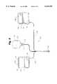
- FIG. 1is a perspective view of an automated external defibrillator
- FIG. 2is an exploded view of an electrode having the force sensor of the present invention
- FIG. 3is a block diagram of an electrical system of the AED
- FIG. 4is a perspective view of the force sensor used in conjunction with a pair of electrodes
- FIG. 5is a perspective view of the force sensor of the present invention applied to a patient
- FIG. 6is a perspective view of an electrode with the force sensor of the present invention disposed therein;
- FIG. 7is a perspective view of the force sensor of FIG. 6 applied to the chest of a victim;
- FIG. 8is a cross sectional side view of the electrode of the present invention.
- FIG. 9is a top plan view of a further embodiment of the force sensor of the present invention.
- FIG. 10is a bottom plan view of the force sensor depicted in FIG. 9;
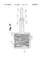
- FIG. 11is a cross sectional side view of the electrode of the present invention.
- FIG. 12is a cross sectional side view of the electrode of the present invention.
- FIG. 13is a top plan view of a further embodiment of the force sensor of the present invention.
- FIG. 14is a bottom plan view of the force sensor depicted in FIG. 13;
- FIG. 15is a cross sectional side view of the electrode of the present invention.
- FIG. 16is a cross sectional side view of the electrode of the present invention.
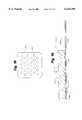
- FIG. 17is a top plan view of a further embodiment of the force sensor of the present invention.
- FIG. 18is a bottom plan view of the force sensor depicted in FIG. 17.
- FIG. 19is a cross sectional side view of the electrode of the present invention.
- AED 22is shown generally at 22 in FIG. 1.
- AED 22is used for emergency treatment of victims of cardiac arrest and is typically used by first responders.
- AED 22automatically analyzes a patient's cardiac electrical signal and advises the user to shock a patient upon detection of: (1) ventricular fibrillation; (2) ventricular tachycardia; (3) other cardiac rhythms with ventricular rates exceeding 180 beats per minute and having amplitudes of at lease 0.15 millivolts.
- AED 22will build up an electrical charge for delivery to the patient to defibrillate the patient with a defibrillation shock.
- the operator of AED 22is guided by voice prompts and an illuminated rescue (shock) button.
- Olson, et al. U.S. Pat. No. 5,645,571incorporated herein by reference, discloses the general construction and manner of use of an AED.
- AED 22includes case 12 with carrying handle 14 and battery 80, the battery 80 being removably disposed within a battery compartment (not shown) defined in case 12. Battery 80 functions as an energy source for AED 22.
- Visual maintenance indicator 20 and data access door 44are located on the outside of case 12 to facilitate access by the operator.
- a data communication serial port 42is situated behind data access door 44.
- Case 12also includes panel 24 and electrode compartment 26 defined in a top portion thereof. Panel 24 includes illuminable rescue switch 18 and diagnostic display panel 36 with "electrodes" indicator light 28. Panel 24 and electrode compartment 26 are enclosed by selectively closeable lid 27.
- Electrode compartment 26contains connector 32 and electrode package 60. Electrode compartment 26 hermetically encloses a patient interface which includes a pair of electrodes 50 depicted in FIG. 2, and a force sensor 200, FIGS. 4-16. Electrodes 50 and force sensor 200 are removably connected to connector 32 by lead wires 52 and lead wire connector 58. Electrodes 50 are attachable to a patient prior to a rescue intervention procedure with AED 22.
- AED 22also includes a digital microprocessor-based electrical control system (see the block diagram of FIG. 3) for controlling overall operation of AED 22 and for delivering a defibrillation shock pulse through electrodes 50 via connector 32 and lead wires 52.
- the electrical control systemfurther includes an impedance measuring circuit for testing the interconnection and operability of electrodes 50 to detect several faults. For example, if the conductive hydrogel adhesive on electrodes 50 is too dry or if electrodes 50 are not properly connected to connector 32 a relatively high impedance (e.g. greater than about 20 ohms) will be present across connector 32. However, when fresh electrodes 50 are properly connected, the impedance across connector 32 will be between about 2 and 10 ohms.
- an electrode self-testis conducted (e.g., daily or upon opening lid 27) in which the interconnection and operability of electrodes 50 are checked with the impedance measuring circuit. If electrodes 50 are missing or unplugged from connector 32, if electrodes 50 are damaged, or if the conductive hydrogel adhesive on electrodes 50 is too dry, the control system of AED 22 will illuminate "Electrodes" indicator light 28 on diagnostic display panel 36.
- FIG. 2is an exploded view of a prior art electrode 50.
- Electrode 50includes flexible, adhesive coated backing layer 53 (preferably a polymeric foam), and patient engaging layer 54.
- Patient engaging layer 54is preferably a hydrogel material which has adhesive properties and which is electrically conductive. Hydrogel adhesive of this type is commercially available from LecTec Corporation (Minnetonka, Minn.) and Tyco International Ltd. (Hamilton, Bermuda).
- Current disbursing flexible conductive portion 56is preferably located between backing layer 53 and patient-engaging hydrogel layer 54.
- Conductive portion 56, as shown,need not be the same size as backing layer 53 and is preferably a homogeneous, solid, thinly deposited metallic substance, or a conductive ink.
- Insulated lead wire 52is terminated with a wire terminal 70.
- Wire terminal 70is electrically connected to conductive portion 56 via conductive rivet 74 and washer 72.
- Conductive rivet 74is covered on a first side with insulating disk 76.
- Conductive rivet 74, washer 72, and wire terminal 70are all covered on a second side with insulating pad 78.
- Further examples of electrode pad construction for use with AED 22are described and shown in U.S. Pat. Nos. 5,697,955, 5,579,919, and 5,402,884, all hereby incorporated by reference.
- FIG. 3is a block diagram of electrical system 70 of AED 22.
- the overall operation of AED 22is controlled by a digital microprocessor-based control system 72 which includes a processor 74 interfaced to program memory 76, data memory 77, event memory 78 and real time clock 79.
- the operating program executed by processor 74is stored in program memory 76.
- Electrical poweris provided by the battery 80 which is removably positioned within the battery compartment of AED 22 and is connected to power generation circuit 84.
- Power generation circuit 84is also connected to lid switch 90, watch dog timer 92, real time clock 79 and processor 74.
- Lid switch 90is a magnetic read relay switch in one embodiment, and provides signals to processor 74 indicating whether lid 27 is open or closed.
- Data communication port 42is coupled to processor 74 for two-way serial data transfer using an RS-232 protocol.
- Rescue switch 18, maintenance indicator 20, the indicator lights of diagnostic display panel 36, the voice circuit 94 and piezoelectric audible alarm 96are also connected to processor 74.
- Voice circuit 94is connected to speaker 34. In response to voice prompt control signals from processor 74, circuit 94 and speaker 34 generate audible voice prompts for consideration by a rescuer.
- High voltage generation circuit 86is also connected to and controlled by processor 74. Circuits such as high voltage generation circuit 86 are generally known, and disclosed, for example, in the commonly assigned Persson et al. U.S. Pat. No. 5,405,361, which is hereby incorporated by reference. In response to charge control signals provided by processor 74, high voltage generation circuit 86 is operated in a charge mode during which one set of semiconductor switches (not separately shown) cause a plurality of capacitors (also not shown), to be charged in parallel to the 12V potential supplied by power generation circuit 84.
- high voltage generation circuit 86is operated in a discharge mode during which the capacitors are discharged in series by another set of semiconductor switches (not separately shown) to produce the high voltage defibrillation pulses.
- the defibrillation pulsesare applied to the patient by electrodes 50 through connector 32 connected to the high voltage generation circuit 86.
- Impedance measuring circuit 100is connected to both connector 32 and real time clock 79. Impedance measuring circuit 100 is interfaced to processor 74 through analog-to-digital (A/D) converter 102. Impedance measuring circuit 100 receives a clock signal having a predetermined magnitude from clock 79, and applies the signal to electrodes 50 through connector 32. The magnitude of the clock signal received back from electrodes 50 through connector 32 is monitored by impedance measuring circuit 100. An impedance signal representative of the impedance present across electrodes 50 is then generated by circuit 100 as a function of the ratio of the magnitudes of the applied and received clock signals (i.e., the attenuation of the applied signal).
- a relatively low resistancee.g., less than about 10 ohms
- a relatively high resistancee.g., greater than about two hundred fifty ohms
- the resistance across electrodes 50will then be between about twenty-five and two hundred fifty ohms when fresh electrodes 50 are properly positioned on the patient with good electrical contacts. It should be noted that these resistance values are given as exemplary ranges and are not meant to be absolute ranges.
- the impedance signal representative of the impedance measured by circuit 100is digitized by A/D converter 102 and provided to processor 74.
- Impedance measuring circuit 110is connected to connector 32 and real time clock 79, and is interfaced to processor 74 through analog-to-digital (A/D) converter 102. Impedance measuring circuit 110 receives a clock signal having a predetermined magnitude from clock 79, and applies the signal to force sensor 200 through connector 32. The magnitude of the clock signal received back from force sensor 200 through connector 32 is monitored by impedance measuring circuit 110. An impedance signal representative of the impedance present across force sensor 200 is then generated by circuit 110 as a function of the ratio of the magnitudes of the applied and received clock signals (i.e., the attenuation of the applied signal). The impedance signal representative of the impedance measured by circuit 110 is digitized by A/D converter 102 and provided to processor 74.
- A/D converter 102analog-to-digital converter 102
- FIG. 4is a plan view of a patient interface 120 for use with AED 22.
- Patient interface 120includes connector 58 which is adapted to releasably mate with connector 32 of AED 22.
- Four lead wires 52A, 52B, 52C, and 52Dare all terminated with connector 58.
- Patient interface 120also includes a force sensing pad 102 which includes a force sensor 200.
- Lead wires 52C and 52Dare electrically connected to force sensor 200.
- Electrodes 50A and 50Beach include backing layer 53, patient engaging hydrogel layer 54, conductive portion 56, and insulating pad 78.
- FIG. 5is a plan view illustrating patient interface 120 applied to human torso 98 of the victim 112.
- Force sensing pad 102is applied over the sternum of torso 98.
- Force sensing pad 102may be adhered with pressure sensitive adhesive.
- Force sensing pad 102includes force sensor 200 which is electrically connected to lead wires 52C and 52D.
- Electrode 50Ais shown applied to the upper right chest of torso 98. Electrode 50A is electrically connected to lead wire 52A. Electrode 50B is applied to the lower left side of torso 98 and is electrically connected to lead wire 52B. Lead wires 52A, 52B, 52C, and 52D are terminated with connector 58. Connector 58 is adapted to make releasable, electrical contact with connector 32 of AED 22.
- electrodes 50A, 50B and force sensing pad 102may be placed in locations on torso 98 other than those shown in FIG. 5 without deviating from the spirit or scope of this invention.
- FIG. 6is a plan view of a patient interface 130 for use with AED 22.
- Interface 130includes a second preferred embodiment of force sensor 200.
- Patient interface 130includes connector 58 which is adapted to releasably mate with connector 32 of AED 22.
- Four lead wires 52A, 52B, 52C, and 52Dare all terminated with connector 58.
- Patient interface 130also includes force sensor 200 which is positioned between backing layer 153 and insulating pad 178 of electrode 150A. Lead wires 52C and 52D are electrically connected to force sensor 200.
- Electrodes 150A and 150Beach include patient engaging hydrogel layer 54, and conductive portion 56.
- FIG. 7is a plan view illustrating patient interface 130 applied to torso 98.
- Force sensor 200is positioned over the sternum of torso 98.
- Force sensor 200is electrically connected to lead wires 52C and 52D.
- Electrode 150Ais shown applied to torso 98.
- Electrode 150Ais electrically connected to lead wire 52A.
- Electrode 150Bis applied to the lower left side of torso 98 and is electrically connected to lead wire 52B.
- Lead wires 52A, 52B, 52C, and 52Dare terminated with connector 58 (not shown).
- Connector 58is adapted to make releasable, electrical contact with connector 32 (not shown) of AED 22.
- FIG. 8is a cross section illustrating an embodiment of a force sensor 200.
- Force sensor 200has a first side 210 and a second side 220.
- Force sensor 200includes a substrate 202.
- a conductive pattern 204A, 204Bis situated on each side of the substrate layer.
- Substrate 202may be any thin (e.g. about 0.002" to 0.020") nonconductive sheet of material. Plastic film materials such as polyester, polycarbonate, PVC, etc. have been found to work well as substrate 202.
- Conductive patterns 204A, 204Bmay be any conductive material such as copper foil, nickel foil, or conductive ink. In a preferred embodiment substrate 202 is 5 mil polyester and conductive patterns 204A, 204B are silver conductive ink.
- Substrate 202includes apertures 208.
- Conductive pads 206A and 206Bare situated on each side of substrate 202 as shown in FIG. 8.
- Conductive pads 206A, 206Bare preferably made of a deformable, conductive material. Materials which have been found suitable include conductive silicone rubber, conductive foam rubber, and conductive urethane rubber.
- FIG. 9is a plan view illustrating first side 210 of force sensor 200 with conductive pads 206A, 206B removed.
- Conductive pattern 204Ais seen situated on substrate 202.
- Apertures 208are cut through conductive pattern 204A, substrate 202, and conductive pattern 204B, underlying substrate 202.
- FIG. 10is a plan view illustrating second side 220 of force sensor 200 with conductive pads 206A, 206B removed.
- Conductive pattern 204Bis seen situated on substrate 202.
- apertures 208are cut through conductive pattern 204B, substrate 202, and conductive pattern 204A, underlying substrate 202.
- conductive patterns 204A, 204Beach include conductive traces 212A, 212B.
- Wire terminals 214A, 214Bare arranged make electrical contact with conductive traces 212A, 212B respectively.
- Wire terminals 214A, 214Bare attached to substrate 202 with rivets 216A, 216B and washers 218A, 218B.
- Lead wires 222A, 222Bare terminated with wire terminals 214A, 214B.
- lead wires 222A, 222Bmay be used to attach lead wires 222A, 222B to conductive traces 212A, 212B. Possible methods include soldering, the use of a connector designed to mate with flexible circuits, and the use of conductive adhesive.
- FIG. 11is a section view of force sensor 200 with a compressive force F applied.
- force sensor 200When force sensor 200 is used, it is placed between two objects, such as the sternum of a cardiac arrest victim and the heel of a rescuer's hand. When the rescuer presses down with the heel of his or her hand, the force results in pressure distributed across the area of the heel of his or her hand.
- conductive pads 206A, 206BWhen pressure is applied to force sensor 200, conductive pads 206A, 206B extrude through apertures 208. When pads 206A, 206B contact each other, they complete an electrical circuit between conductive layer 204A and conductive layer 204B. Increasing the force F applied to force sensor 200 increases the surface area of the electrical connection between conductive pads 206A, 206B, thereby decreasing the electrical resistance between pads 206A, 206B. The electrical resistance of the circuit between conductive layer 204A and conductive layer 204B is therefore indicative of the magnitude of the force F applied to force sensor 200.
- FIGS. 12-14illustrate a further preferred embodiment of force sensor 200.
- Force sensor 200includes a first substrate 222.
- a conductive pattern 224is situated on first substrate 222.
- substrate 222may be any thin (e.g. about 0.002" to 0.010") nonconductive sheet of material.
- Plastic film materialssuch as polyester, polycarbonate, PVC, etc. have been found to work well as substrate 222.
- Conductive pattern 224may be any conductive material such as copper foil, nickel foil, or conductive ink.
- substrate layer 222is 5 mil polyester and conductive pattern 224 is silver conductive ink.
- Force sensor 200includes second substrate 226.
- a conductive pattern 228is situated on second substrate 226.
- Second substrate 226is situated on first substrate 222.
- First substrate 222 and second substrate 226may be held together with a layer of pressure sensitive adhesive (not shown).
- Substrate 222includes apertures 230.
- a conductive pad 232is situated on, and makes electrical contact with conductive pattern 224 as shown in FIG. 14.
- Conductive pad 232is preferably made of a deformable, conductive material. Materials which have been found suitable include conductive silicone rubber, conductive foam rubber, and conductive urethane rubber.
- FIG. 13is a plan view illustrating second substrate 226 and conductive pattern 228.
- FIG. 14is a plan view illustrating first substrate 222 and conductive pattern 224.
- FIG. 15is a section view of the force sensor 200 of FIG. 12 with a force F applied.
- force sensor 200When force sensor 200 is used, it is placed between two objects, such as the sternum of a cardiac arrest victim and the heel of a rescuers hand. When the rescuer presses down with the heel of his or her hand, the force results in pressure distributed across the area of the heel of his or her hand.
- conductive pad 232When a force F is applied to force sensor 200, conductive pad 232 extrudes through apertures 230. When conductive pad 232 contacts conductive pattern 228 it completes an electrical circuit between conductive pattern 224 and conductive pattern 228. Increasing the force F applied to force sensor 200 increases the surface area of the electrical connection between conductive pads 232 and conductive pattern 228, thereby reducing the electrical resistance between pad 232 and pattern 228. Accordingly, change in contact area creates a change in electrical resistance which is indicative of the force applied to force sensor 200.
- FIGS. 16-18illustrate another third embodiment of force sensor 200.
- force sensor 200includes a first substrate 242.
- Two conductive patterns 244A, 244Bare situated on first substrate 242.
- Force sensor 200includes second substrate 246 which includes apertures 250.
- Second substrate 246is comprised of a non-conductive material. Polyester, polyethylene, and polypropylene have been found to be suitable materials for second substrate 246.
- a conductive pad 252is situated on second substrate 246.
- conductive pad 232is preferably made of a deformable, conductive material.
- FIG. 17is a plan view illustrating first substrate 242 and conductive patterns 244A, 244B.
- the conductive patterns 244A, 244Bare arranged so that they are in close proximity to each other. Small gaps 256 are left between conductive paths 244A, 244B so that there is no direct electrical contact between conductive paths 244A, 244B.
- FIG. 18is a plan view illustrating second substrate 246 and apertures 250.
- FIG. 19is a section view of the force sensor 200 of FIGS. 16-18 with a force F applied.
- force sensor 200When force sensor 200 is used, it is placed between two objects, such as the sternum of a cardiac arrest victim and the heel of a rescuers hand. When the rescuer presses down with the heel of his or her hand, the force F results in pressure distributed across the area of the heel of his or her hand.
- conductive pad 252When pressure is applied to force sensor 200, conductive pad 252 extrudes through apertures 250. When conductive pad 252 contacts conductive patterns 244A, 244B it completes an electrical circuit between conductive pattern 244A and conductive pattern 244B. Increasing the force applied to force sensor 200 increases the surface area of the electrical connection between conductive pad 252 and conductive patterns 244A, 244B. This change in contact area creates a change in electrical resistance which is indicative of the force applied to force sensor 200.
- force sensor 200is positioned on the sternum of a victim 112.
- the rescuerplaces the heel of his or her hand onto force sensor 200 and delivers chest compressions to the chest of the victim 112.
- Force sensor 200 and impedance measuring circuit 110produce an electrical signal proportional to the force applied to the victim's chest. This signal indicates to processor 74 the rate and magnitude of the chest compressions which the victim 112 is receiving. This signal also allows processor 74 to determine the precise time that a rescuer has begun (or stopped) CPR.
- Processor 74compares the measured rate of chest compressions to a range of desired values.
- processor 74will produce a control signal which causes voice circuit 94 and speaker 34 to generate an appropriate voice prompt such as "faster”. If the current chest compression rate value is greater than the desired range, processor 74 will produce a control signal which causes voice circuit 94 and speaker 34 to generate an appropriate voice prompt such as "slower”.
- Processor 74also compares the measured chest compression force to a range of desired values. If the chest compression force delivered by the rescuer is less than the desired range, processor 74 will produce a control signal which causes voice circuit 94 and speaker 34 to generate an appropriate voice prompt such as "harder”. If the chest compression force is greater than the desired range, processor will produce a control signal which causes voice circuit 94 and speaker 34 to generate an appropriate voice prompt such as "softer".
- AED 22may also provide other types of audible feedback to the rescuer.
- AED 22may give an audible signal each time the force measured using force sensor 200 reaches a desired value.
Landscapes
- Health & Medical Sciences (AREA)
- Cardiology (AREA)
- Heart & Thoracic Surgery (AREA)
- Animal Behavior & Ethology (AREA)
- Veterinary Medicine (AREA)
- Public Health (AREA)
- General Health & Medical Sciences (AREA)
- Life Sciences & Earth Sciences (AREA)
- Biomedical Technology (AREA)
- Radiology & Medical Imaging (AREA)
- Nuclear Medicine, Radiotherapy & Molecular Imaging (AREA)
- Engineering & Computer Science (AREA)
- Emergency Medicine (AREA)
- Pulmonology (AREA)
- Epidemiology (AREA)
- Pain & Pain Management (AREA)
- Physical Education & Sports Medicine (AREA)
- Rehabilitation Therapy (AREA)
- Electrotherapy Devices (AREA)
Abstract
Description
Claims (27)
Priority Applications (2)
| Application Number | Priority Date | Filing Date | Title |
|---|---|---|---|
| US09/182,831US6125299A (en) | 1998-10-29 | 1998-10-29 | AED with force sensor |
| US10/255,988USRE40471E1 (en) | 1998-10-29 | 2002-09-25 | AED with force sensor |
Applications Claiming Priority (1)
| Application Number | Priority Date | Filing Date | Title |
|---|---|---|---|
| US09/182,831US6125299A (en) | 1998-10-29 | 1998-10-29 | AED with force sensor |
Related Child Applications (1)
| Application Number | Title | Priority Date | Filing Date |
|---|---|---|---|
| US10/255,988ReissueUSRE40471E1 (en) | 1998-10-29 | 2002-09-25 | AED with force sensor |
Publications (1)
| Publication Number | Publication Date |
|---|---|
| US6125299Atrue US6125299A (en) | 2000-09-26 |
Family
ID=22670234
Family Applications (2)
| Application Number | Title | Priority Date | Filing Date |
|---|---|---|---|
| US09/182,831CeasedUS6125299A (en) | 1998-10-29 | 1998-10-29 | AED with force sensor |
| US10/255,988Expired - LifetimeUSRE40471E1 (en) | 1998-10-29 | 2002-09-25 | AED with force sensor |
Family Applications After (1)
| Application Number | Title | Priority Date | Filing Date |
|---|---|---|---|
| US10/255,988Expired - LifetimeUSRE40471E1 (en) | 1998-10-29 | 2002-09-25 | AED with force sensor |
Country Status (1)
| Country | Link |
|---|---|
| US (2) | US6125299A (en) |
Cited By (95)
| Publication number | Priority date | Publication date | Assignee | Title |
|---|---|---|---|---|
| WO2001056652A1 (en)* | 2000-02-04 | 2001-08-09 | Zmd Corporation | Integrated resuscitation |
| US6306107B1 (en)* | 1999-05-31 | 2001-10-23 | Laerdal Medical As | System for measuring and using parameters during chest compression in a life-saving situation or a practice situation, and also application thereof |
| US6351671B1 (en)* | 1998-12-11 | 2002-02-26 | Laerdal Medical As | System for measuring and analyzing cardio-pulmonary-resuscitation (CPR) parameters for use with and by an external defibrillator (AED) or a training defibrillator |
| EP1264615A2 (en) | 2001-06-08 | 2002-12-11 | Corscience GmbH & CO.KG | Therapy device |
| US20030060723A1 (en)* | 1999-09-30 | 2003-03-27 | Medtronic Physio-Control Manufacturing Corp. | Pulse detection apparatus, software, and methods using patient physiological signals |
| US20030216785A1 (en)* | 2002-05-15 | 2003-11-20 | Edwards D. Craig | User interface method and apparatus for a medical device |
| US6676613B2 (en) | 1997-10-17 | 2004-01-13 | Elroy T. Cantrell | Chest mounted cardio pulmonary resuscitation device and system |
| US20040039420A1 (en)* | 2002-08-26 | 2004-02-26 | Medtronic Physio-Control Manufacturing Corp. | Apparatus, software, and methods for cardiac pulse detection using accelerometer data |
| WO2004037154A2 (en) | 2002-10-25 | 2004-05-06 | Revivant Corporation | Method of determining depth of compressions during cardio-pulmonary resuscitation |
| US6767424B1 (en)* | 1998-10-20 | 2004-07-27 | Henkel Kommanditgesellschaft Auf Aktien | Hot-melt adhesive for glueing DVDs |
| US20040162587A1 (en)* | 2003-02-14 | 2004-08-19 | Medtronic Physio-Control Corp. | Cooperating defibrillators and external chest compression devices |
| US20040162510A1 (en)* | 2003-02-14 | 2004-08-19 | Medtronic Physio-Control Corp | Integrated external chest compression and defibrillation devices and methods of operation |
| US20040267324A1 (en)* | 2003-06-27 | 2004-12-30 | Frederick Geheb | Cardio-pulmonary resuscitation device with feedback from measurement of pulse and/or blood oxygenation |
| US20040267325A1 (en)* | 2003-06-27 | 2004-12-30 | Frederick Geheb | Method and apparatus for enhancement of chest compressions during CPR |
| US20050038475A1 (en)* | 2003-02-18 | 2005-02-17 | Medtronic Physio-Control Corp. | Defibrillators learning of other concurrent therapy |
| US20050070963A1 (en)* | 2003-09-30 | 2005-03-31 | Wilson Ellen Bartlett | Hair-removal apparatus for preparing a human torso for the use of an automated external defibrillator |
| US20050101889A1 (en)* | 2003-11-06 | 2005-05-12 | Freeman Gary A. | Using chest velocity to process physiological signals to remove chest compression artifacts |
| US20050131465A1 (en)* | 2000-02-04 | 2005-06-16 | Freeman Gary A. | Integrated resuscitation |
| US6961612B2 (en) | 2003-02-19 | 2005-11-01 | Zoll Medical Corporation | CPR sensitive ECG analysis in an automatic external defibrillator |
| US20050251213A1 (en)* | 2004-05-07 | 2005-11-10 | Freeman Gary A | Automated caregiving device with prompting based on caregiver progress |
| US20050256415A1 (en)* | 2004-05-12 | 2005-11-17 | Qing Tan | ECG rhythm advisory method |
| US20050267536A1 (en)* | 2004-04-12 | 2005-12-01 | Freeman Gary A | Automated pediatric defibrillator |
| US20060015044A1 (en)* | 2004-07-15 | 2006-01-19 | Mette Stavland | Method and system for monitoring ventilations and compressions delivered to a patient |
| US20060025824A1 (en)* | 2004-05-12 | 2006-02-02 | Freeman Gary A | Automatic therapy advisor |
| US20060022645A1 (en)* | 2004-07-30 | 2006-02-02 | Bowers Kyle R | Method and apparatus for determining battery capacity in a defibrillator |
| US20060064131A1 (en)* | 2000-02-04 | 2006-03-23 | Freeman Gary A | User interface for defibrillator for use by persons with limited training and experience |
| US20060070822A1 (en)* | 2003-06-18 | 2006-04-06 | Toshiba Elevator Kabushiki Kaisha | Sheave for elevator |
| US20060142810A1 (en)* | 2003-06-27 | 2006-06-29 | Douglas Denney | Method of detecting when electrode pads have been handled or removed from their package |
| US20060167515A1 (en)* | 1999-09-30 | 2006-07-27 | Medtronic Emergency Response | Apparatus, software, and methods for cardiac pulse detection using a piezoelectric sensor |
| US20060173500A1 (en)* | 2005-01-31 | 2006-08-03 | Medtronic Emergency Response Systems, Inc. | CPR time indicator for a defibrillator data management system |
| US20070060785A1 (en)* | 2005-09-14 | 2007-03-15 | Freeman Gary A | Synchronization of repetitive therapeutic interventions |
| WO2007057825A2 (en) | 2005-11-17 | 2007-05-24 | Koninklijke Philips Electronics, N.V. | Cpr guided by vascular flow measurement |
| US20070219588A1 (en)* | 2006-03-17 | 2007-09-20 | Freeman Gary A | Automated resuscitation device with ventilation sensing and prompting |
| US20070276300A1 (en)* | 2006-05-26 | 2007-11-29 | Olson Kenneth F | Cpr feedback method and apparatus |
| WO2008059394A1 (en) | 2006-11-14 | 2008-05-22 | Koninklijke Philips Electronics, N.V. | Cpr coaching device with reduced sensitivity to motion |
| US20080208273A1 (en)* | 2002-08-26 | 2008-08-28 | Owen James M | Pulse Detection Using Patient Physiological Signals |
| US20080300518A1 (en)* | 2007-06-01 | 2008-12-04 | Bowes C J | System, method, and apparatus for assisting a rescuer in resuscitation |
| US20090024175A1 (en)* | 2006-02-15 | 2009-01-22 | Koninklijke Philips Electronics, N.V. | Cpr assistance and effectiveness display |
| US7569018B1 (en) | 2003-02-18 | 2009-08-04 | Purdue Research Foundation | Apparatus and method for noninvasively detecting the quality of cardiac pumping |
| US20090240295A1 (en)* | 2005-11-18 | 2009-09-24 | Scientific Pathways International, Llc | Cpr analysis system and method |
| WO2010097728A1 (en) | 2009-02-24 | 2010-09-02 | Koninklijke Philips Electronics, N.V. | Ultrasonic vascular flow sensor with triangular sensor geometry |
| EP2228097A1 (en) | 2009-03-11 | 2010-09-15 | Schiller Medical S.A.S. | Defibrillator, rescue kit of parts and process for controlling the quality of chest compressions |
| US7822471B2 (en) | 2004-07-30 | 2010-10-26 | Access Cardiosystems, Inc. | Method and apparatus for detecting artifact signals in the electrocardiogram of a patient caused by CPR and/or patient motion using patient impedance |
| US20110105930A1 (en)* | 2009-11-03 | 2011-05-05 | Srikanth Thiagarajan | True ecg measurement during cardio pulmonary resuscitation by adaptive piecewise stitching algorithm |
| US8092392B2 (en) | 1999-09-30 | 2012-01-10 | Physio-Control, Inc. | Pulse detection method and apparatus using patient impedance |
| USD671649S1 (en) | 2011-12-07 | 2012-11-27 | Cardiac Sciences Corporation | Cardiopulmonary resuscitation assist device |
| WO2013058818A3 (en)* | 2011-04-08 | 2013-12-27 | Zoll Medical Corporation | Coordinated resuscitation perfusion support |
| US8668670B2 (en) | 2004-06-23 | 2014-03-11 | Abbvie Biotechnology Ltd | Automatic injection devices |
| US8798743B1 (en)* | 2013-03-04 | 2014-08-05 | Zoll Medical Corporation | Self-contained cardiac response unit |
| US8942800B2 (en) | 2012-04-20 | 2015-01-27 | Cardiac Science Corporation | Corrective prompting system for appropriate chest compressions |
| WO2015013680A1 (en)* | 2013-07-25 | 2015-01-29 | Physio-Control, Inc. | Electrode assembly having various communicative solutions |
| US9107800B2 (en) | 2002-03-21 | 2015-08-18 | Physio-Control, Inc. | Front part for support structure for CPR |
| US9248306B2 (en) | 1999-09-30 | 2016-02-02 | Physio-Control, Inc. | Pulse detection apparatus, software, and methods using patient physiological signals |
| US20160184180A1 (en)* | 2014-12-26 | 2016-06-30 | Sumitomo Riko Company Limited | Cardiopulmonary resuscitation support device |
| JP2016123844A (en)* | 2014-12-26 | 2016-07-11 | 住友理工株式会社 | Cardiopulmonary resuscitation assisting apparatus |
| US9443445B2 (en) | 2012-03-02 | 2016-09-13 | Abbvie Inc. | Automatic injection training device |
| US9468581B2 (en) | 2010-11-29 | 2016-10-18 | Hitachi, Ltd. | Compression depth calculation system and compression depth calculation method |
| US9486584B2 (en) | 2006-06-30 | 2016-11-08 | Abbvie Biotechnology Ltd. | Automatic injection device |
| US9642575B2 (en) | 2013-03-15 | 2017-05-09 | Zoll Medical Corporation | ECG noise reduction system for removal of vehicle motion artifact |
| US20170281463A1 (en)* | 1998-11-09 | 2017-10-05 | The Johns Hopkins University | ECG Artifact Reduction System |
| US20170281461A1 (en)* | 2016-03-30 | 2017-10-05 | Sumitomo Riko Company Limited | Cardiopulmonary resuscitation support device |
| US9878102B2 (en) | 2011-01-24 | 2018-01-30 | Abbvie Biotechnology Ltd. | Automatic injection devices having overmolded gripping surfaces |
| CN107812324A (en)* | 2017-11-24 | 2018-03-20 | 合肥大族科瑞达激光设备有限公司 | A kind of semiconductor laser therapeutic instrument |
| US9968267B2 (en) | 2013-03-15 | 2018-05-15 | Zoll Medical Corporation | Processing impedance signals for breath detection |
| US10004662B2 (en) | 2014-06-06 | 2018-06-26 | Physio-Control, Inc. | Adjustable piston |
| US10029109B2 (en) | 2016-12-12 | 2018-07-24 | Revive Solutions, Inc. | Defibrillator |
| US10092464B2 (en) | 2014-10-03 | 2018-10-09 | Physio-Control, Inc. | Medical device stabilization strap |
| US10238574B2 (en) | 2011-04-08 | 2019-03-26 | Zoll Medical Corporation | System for assisting rescuers in performing cardio-pulmonary resuscitation (CPR) on a patient |
| US10322060B2 (en) | 2013-09-25 | 2019-06-18 | Zoll Medical Corporation | Mobile device control |
| US10406345B2 (en) | 2015-10-16 | 2019-09-10 | Zoll Medical Corporation | Dual sensor electrodes for providing enhanced resuscitation feedback |
| US10420702B2 (en) | 2013-02-20 | 2019-09-24 | Physio-Control, Inc. | CPR quality assessment accounting for pause aspect |
| US10449380B2 (en) | 2016-12-12 | 2019-10-22 | Revive Solutions, Inc. | Defibrillator |
| US10490308B2 (en) | 2013-02-20 | 2019-11-26 | Physio-Control, Inc. | Context-sensitive chest compression fraction measurement for CPR quality assessment |
| US10596064B2 (en) | 2014-03-18 | 2020-03-24 | Zoll Medical Corporation | CPR chest compression system with tonometric input and feedback |
| US10610679B2 (en) | 2015-03-27 | 2020-04-07 | Zoll Medical Corporation | ECG and defibrillator electrode detection and tracking system and method |
| US10639234B2 (en) | 2015-10-16 | 2020-05-05 | Zoll Circulation, Inc. | Automated chest compression device |
| US10682282B2 (en) | 2015-10-16 | 2020-06-16 | Zoll Circulation, Inc. | Automated chest compression device |
| US10874583B2 (en) | 2017-04-20 | 2020-12-29 | Zoll Circulation, Inc. | Compression belt assembly for a chest compression device |
| US10903675B2 (en) | 2016-12-12 | 2021-01-26 | Avive Solutions, Inc. | Medical device draw current regulation |
| US10905629B2 (en) | 2018-03-30 | 2021-02-02 | Zoll Circulation, Inc. | CPR compression device with cooling system and battery removal detection |
| US10993626B2 (en) | 2012-06-29 | 2021-05-04 | Zoll Medical Corporation | Rescue scene video transmission |
| USD926323S1 (en) | 2020-03-30 | 2021-07-27 | Zoll Medical Corporation | Automated external defibrillator electrode pad |
| US11179286B2 (en) | 2016-10-21 | 2021-11-23 | Zoll Medical Corporation | Adaptive body positioning |
| US20220008287A1 (en)* | 2011-07-27 | 2022-01-13 | Zoll Medical Corporation | Method and apparatus for monitoring manual chest compression efficiently during cpr |
| US11246795B2 (en) | 2017-04-20 | 2022-02-15 | Zoll Circulation, Inc. | Compression belt assembly for a chest compression device |
| US11246796B2 (en) | 2014-06-06 | 2022-02-15 | Physio-Control, Inc. | Adjustable piston |
| US11607555B2 (en) | 2016-12-12 | 2023-03-21 | Avive Solutions, Inc. | Defibrillator discharge control |
| US11666507B2 (en) | 2005-03-25 | 2023-06-06 | Zoll Medical Corporation | Integrated resuscitation |
| US11794025B1 (en) | 2022-04-04 | 2023-10-24 | Altrix Medical, Inc. | Compact AED with integrated CPR coaching |
| US11944582B2 (en) | 2013-04-30 | 2024-04-02 | Zoll Medical Corporation | Compression depth monitor with variable release velocity feedback |
| US12023296B2 (en) | 2003-11-06 | 2024-07-02 | Zoll Medical Corporation | Method and apparatus for enhancement of chest compressions during CPR |
| US12214211B2 (en) | 2020-09-04 | 2025-02-04 | Zoll Medical Corporation | Medical treatment system with companion device |
| US12233020B2 (en) | 2016-10-21 | 2025-02-25 | Zoll Medical Corporation | System and methods for adaptive body positioning during chest compressions |
| USD1084345S1 (en) | 2022-07-28 | 2025-07-15 | Zoll Medical Corporation | Chest compression sensor |
| USD1084346S1 (en) | 2022-07-28 | 2025-07-15 | Zoll Medical Corporation | Chest compression sensor |
Families Citing this family (9)
| Publication number | Priority date | Publication date | Assignee | Title |
|---|---|---|---|---|
| US7937146B2 (en)* | 2005-01-26 | 2011-05-03 | Physio-Control, Inc. | Defibrillator with overridable CPR-first protocol |
| US9370462B2 (en) | 2010-06-30 | 2016-06-21 | Koninklijke Philips N.V. | Pediatric patient-safe CPR device |
| US9881521B2 (en)* | 2011-01-17 | 2018-01-30 | Prestan Products Llc | Manikin sensing pads and liners in an AED training system |
| USD675739S1 (en) | 2011-12-07 | 2013-02-05 | Cardiac Science Corporation | Automated external defibrillator electrode pad |
| US9126055B2 (en) | 2012-04-20 | 2015-09-08 | Cardiac Science Corporation | AED faster time to shock method and device |
| US8929980B2 (en)* | 2012-05-03 | 2015-01-06 | Physio-Control, Inc. | External defibrillator electrode, method and system for reducing ECG artifact |
| KR101391001B1 (en)* | 2012-10-10 | 2014-05-02 | 주식회사 비티 | simulator for training of CPR and defibrillator |
| US20210285835A1 (en)* | 2020-03-16 | 2021-09-16 | New York University | Apparatus for Determining Shear Forces in Regard to a Pressure Imaging Array, Single Point Sensor for Shear Forces, and Method |
| US12042653B2 (en) | 2021-12-30 | 2024-07-23 | Pulse Biosciences, Inc. | Electrical applicators with non-penetrating electrodes for applying energy to tissue surfaces |
Citations (6)
| Publication number | Priority date | Publication date | Assignee | Title |
|---|---|---|---|---|
| US4273114A (en)* | 1978-10-19 | 1981-06-16 | Michigan Instruments, Inc. | Cardiopulmonary resuscitator, defibrillator and monitor |
| US4619265A (en)* | 1984-03-08 | 1986-10-28 | Physio-Control Corporation | Interactive portable defibrillator including ECG detection circuit |
| US5228449A (en)* | 1991-01-22 | 1993-07-20 | Athanasios G. Christ | System and method for detecting out-of-hospital cardiac emergencies and summoning emergency assistance |
| US5484391A (en)* | 1992-07-30 | 1996-01-16 | Univ Temple | Direct manual cardiac compression method |
| US5838244A (en)* | 1996-10-08 | 1998-11-17 | Cleveland Medical Devices Inc. | Interface pressure measurement device |
| US5853292A (en)* | 1996-05-08 | 1998-12-29 | Gaumard Scientific Company, Inc. | Computerized education system for teaching patient care |
Family Cites Families (52)
| Publication number | Priority date | Publication date | Assignee | Title |
|---|---|---|---|---|
| US3685645A (en) | 1970-08-17 | 1972-08-22 | Physio Control Corp | Defibrillation electrode pad and package therefor |
| US3857398A (en) | 1971-12-13 | 1974-12-31 | L Rubin | Electrical cardiac defibrillator |
| US3862636A (en) | 1972-01-20 | 1975-01-28 | Health Technology Labs Inc | Computer controlled defibrillator |
| US4034854A (en) | 1976-07-16 | 1977-07-12 | M I Systems, Inc. | Electrode package |
| US4096856A (en) | 1976-09-03 | 1978-06-27 | Physio-Control Corporation | Portable electronic physiological instrument having separable first and second components, and improved mechanical connector therefor |
| US4439810A (en) | 1981-09-10 | 1984-03-27 | Marcon Electronics Co., Ltd. | Electric capacitor with enclosure structure consisting of plastic laminated film |
| US4610254A (en) | 1984-03-08 | 1986-09-09 | Physio-Control Corporation | Interactive portable defibrillator |
| US4776350A (en) | 1986-01-07 | 1988-10-11 | Physio-Control Corporation | External electrode for heart stimulation and connector therefor |
| US4779630A (en) | 1987-09-18 | 1988-10-25 | Katecho, Inc. | Defibrillator pad assembly and method for using same |
| US4945477A (en) | 1987-10-22 | 1990-07-31 | First Medic | Medical information system |
| US4979517A (en) | 1988-02-01 | 1990-12-25 | Physio-Control Corporation | Disposable stimulation electrode with long shelf life and improved current density profile |
| US4919144A (en) | 1988-02-26 | 1990-04-24 | First Medic | Defibrillator ECG interpreter |
| AU632647B2 (en) | 1990-01-09 | 1993-01-07 | Physio-Control Corporation | Training electrode for use in defibrillator/monitor instruction and method of instruction |
| US5205284A (en) | 1990-06-12 | 1993-04-27 | Zoll Medical Corporation | Method and apparatus for transcutaneous electrical cardiac pacing with background stimulation |
| US5150708A (en) | 1990-12-03 | 1992-09-29 | Spacelabs, Inc. | Tabbed defibrillator electrode pad |
| US5237989A (en) | 1991-04-04 | 1993-08-24 | Physio-Control Corporation | Cardiac defibrillator with movable contact switch |
| US5247939A (en) | 1992-01-10 | 1993-09-28 | Physio-Control Corporation | Detection of electrode/patient motion and fast restore limits |
| US5275158A (en) | 1992-02-21 | 1994-01-04 | Zmd Corporation | Defibrillation electrode switch condition sensing |
| US5330526A (en) | 1992-05-01 | 1994-07-19 | Zmd Corporation | Combined defibrillation and pacing electrode |
| US5984102A (en) | 1992-09-24 | 1999-11-16 | Survivalink Corporation | Medical electrode packaging technology |
| US5402884A (en) | 1992-09-24 | 1995-04-04 | Surviva Link Corporation | Medical electrode packaging technology |
| US5405361A (en) | 1993-03-15 | 1995-04-11 | Surviva Link Corporation | External defibrillator circuit |
| US5484452A (en) | 1993-03-31 | 1996-01-16 | Surviva-Link Corporation | Current leakage prevention mechanism for use in a defibrillator circuit |
| US5441520A (en) | 1993-04-06 | 1995-08-15 | Hewlett-Packard Corporation | Defibrillator patient connection system with automatic identification |
| US5879374A (en) | 1993-05-18 | 1999-03-09 | Heartstream, Inc. | External defibrillator with automatic self-testing prior to use |
| US5466244A (en) | 1993-05-18 | 1995-11-14 | Heartstream, Inc. | Defibrillator electrode system |
| US5601612A (en) | 1993-08-06 | 1997-02-11 | Heartstream, Inc. | Method for applying a multiphasic waveform |
| US5462157A (en) | 1993-10-28 | 1995-10-31 | Zmd Corporation | Electrode package |
| FR2714761B1 (en) | 1993-12-31 | 1996-03-15 | Ela Medical Sa | Method for configuring an active implantable device by adjusting parameters. |
| US5507778A (en) | 1994-02-22 | 1996-04-16 | Zmd Corporation | Semiautomatic defibrillator with synchronized shock delivery |
| US5391187A (en) | 1994-02-22 | 1995-02-21 | Zmd Corporation | Semiautomatic defibrillator with heart rate alarm driven by shock advisory algorithm |
| US5520683A (en) | 1994-05-16 | 1996-05-28 | Physiometrix, Inc. | Medical electrode and method |
| US5456710A (en) | 1994-06-30 | 1995-10-10 | Physio-Control Corporation | Vented electrode |
| US5549115A (en) | 1994-09-28 | 1996-08-27 | Heartstream, Inc. | Method and apparatus for gathering event data using a removable data storage medium and clock |
| US5593426A (en) | 1994-12-07 | 1997-01-14 | Heartstream, Inc. | Defibrillator system using multiple external defibrillators and a communications network |
| US5611815A (en) | 1994-12-08 | 1997-03-18 | Heartstream, Inc. | Defibrillator with training features |
| US5650750A (en) | 1995-03-03 | 1997-07-22 | Heartstream, Inc. | Common mode signal and circuit fault detection in differential signal detectors |
| US5620465A (en) | 1995-06-08 | 1997-04-15 | Survivalink Corporation | External defibrillator for producing and testing biphasic waveforms |
| US5743864A (en) | 1995-06-29 | 1998-04-28 | Michigan Instruments, Inc. | Method and apparatus for performing cardio-pulmonary resuscitation with active reshaping of chest |
| US5797969A (en) | 1995-08-01 | 1998-08-25 | Survivalink Corporation | One button lid activated automatic external defibrillator |
| US5645571B1 (en) | 1995-08-01 | 1999-08-24 | Surviva Link Corp | Automated external defibrillator with lid activated self-test system |
| US5683423A (en) | 1996-03-14 | 1997-11-04 | Hewlett-Packard Company | Defibrillator and method for storing selected segments of audio data |
| US5716380A (en) | 1996-04-15 | 1998-02-10 | Physio-Control Corporation | Common therapy/data port for a portable defibrillator |
| US5741305A (en) | 1996-05-06 | 1998-04-21 | Physio-Control Corporation | Keyed self-latching battery pack for a portable defibrillator |
| US5697955A (en) | 1996-05-10 | 1997-12-16 | Survivalink Corporation | Defibrillator electrodes and date code detector circuit |
| US5817151A (en) | 1996-06-04 | 1998-10-06 | Survivalink Corporation | Circuit detectable packaged medical electrodes |
| US5836993A (en) | 1996-05-16 | 1998-11-17 | Heartstream, Inc. | Electrotherapy device control system and method |
| US6090056A (en)* | 1997-08-27 | 2000-07-18 | Emergency Medical Systems, Inc. | Resuscitation and alert system |
| DE69829358T2 (en)* | 1997-11-06 | 2006-04-06 | Koninklijke Philips Electronics N.V. | EXTERNAL DEFIBRILLATOR WITH CPR INDICATIONS AND WITH ACLS INDICATIONS |
| US6213960B1 (en)* | 1998-06-19 | 2001-04-10 | Revivant Corporation | Chest compression device with electro-stimulation |
| US6178357B1 (en)* | 1998-08-28 | 2001-01-23 | Agilent Technologies, Inc. | Electrode pad system and defibrillator electrode pad that reduces the risk of peripheral shock |
| ES2235823T3 (en)* | 2000-05-26 | 2005-07-16 | Laerdal Medical As | SYSTEM FOR MEASURING AND ANALYZING CARDIO-PULMONARY RESUSCIATION PARAMETERS (CPR) FOR USE WITH AND BY EXTERNAL DEFIBRILLATOR (AED). |
- 1998
- 1998-10-29USUS09/182,831patent/US6125299A/ennot_activeCeased
- 2002
- 2002-09-25USUS10/255,988patent/USRE40471E1/ennot_activeExpired - Lifetime
Patent Citations (6)
| Publication number | Priority date | Publication date | Assignee | Title |
|---|---|---|---|---|
| US4273114A (en)* | 1978-10-19 | 1981-06-16 | Michigan Instruments, Inc. | Cardiopulmonary resuscitator, defibrillator and monitor |
| US4619265A (en)* | 1984-03-08 | 1986-10-28 | Physio-Control Corporation | Interactive portable defibrillator including ECG detection circuit |
| US5228449A (en)* | 1991-01-22 | 1993-07-20 | Athanasios G. Christ | System and method for detecting out-of-hospital cardiac emergencies and summoning emergency assistance |
| US5484391A (en)* | 1992-07-30 | 1996-01-16 | Univ Temple | Direct manual cardiac compression method |
| US5853292A (en)* | 1996-05-08 | 1998-12-29 | Gaumard Scientific Company, Inc. | Computerized education system for teaching patient care |
| US5838244A (en)* | 1996-10-08 | 1998-11-17 | Cleveland Medical Devices Inc. | Interface pressure measurement device |
Cited By (274)
| Publication number | Priority date | Publication date | Assignee | Title |
|---|---|---|---|---|
| US6676613B2 (en) | 1997-10-17 | 2004-01-13 | Elroy T. Cantrell | Chest mounted cardio pulmonary resuscitation device and system |
| US20040116840A1 (en)* | 1997-10-17 | 2004-06-17 | Cantrell Elroy T. | Chest mounted cardio pulmonary resuscitation device and system |
| US6767424B1 (en)* | 1998-10-20 | 2004-07-27 | Henkel Kommanditgesellschaft Auf Aktien | Hot-melt adhesive for glueing DVDs |
| US20170281463A1 (en)* | 1998-11-09 | 2017-10-05 | The Johns Hopkins University | ECG Artifact Reduction System |
| US6351671B1 (en)* | 1998-12-11 | 2002-02-26 | Laerdal Medical As | System for measuring and analyzing cardio-pulmonary-resuscitation (CPR) parameters for use with and by an external defibrillator (AED) or a training defibrillator |
| US6306107B1 (en)* | 1999-05-31 | 2001-10-23 | Laerdal Medical As | System for measuring and using parameters during chest compression in a life-saving situation or a practice situation, and also application thereof |
| US8092392B2 (en) | 1999-09-30 | 2012-01-10 | Physio-Control, Inc. | Pulse detection method and apparatus using patient impedance |
| US9248306B2 (en) | 1999-09-30 | 2016-02-02 | Physio-Control, Inc. | Pulse detection apparatus, software, and methods using patient physiological signals |
| US8532766B2 (en)* | 1999-09-30 | 2013-09-10 | Physio-Control, Inc. | Pulse detection apparatus, software, and methods using patient physiological signals |
| US9981142B2 (en) | 1999-09-30 | 2018-05-29 | Physio-Control, Inc. | Pulse detection apparatus, software, and methods using patient physiological signals |
| US8239024B2 (en)* | 1999-09-30 | 2012-08-07 | Physio-Control, Inc. | Pulse detection apparatus, software, and methods using patient physiological signals |
| US8744577B2 (en) | 1999-09-30 | 2014-06-03 | Physio-Control, Inc. | Pulse detection apparatus, software, and methods using patient physiological signals |
| US20050240234A1 (en)* | 1999-09-30 | 2005-10-27 | Medtronic Emergency Response Systems, Inc. | Pulse detection apparatus, software, and methods using patient physiological signals |
| US20120022339A1 (en)* | 1999-09-30 | 2012-01-26 | Physio-Control, Inc. | Pulse detection apparatus, software, and methods using patient physiological signals |
| US7917209B2 (en)* | 1999-09-30 | 2011-03-29 | Physio-Control, Inc. | Pulse detection apparatus, software, and methods using patient physiological signals |
| US20030060723A1 (en)* | 1999-09-30 | 2003-03-27 | Medtronic Physio-Control Manufacturing Corp. | Pulse detection apparatus, software, and methods using patient physiological signals |
| US20060167515A1 (en)* | 1999-09-30 | 2006-07-27 | Medtronic Emergency Response | Apparatus, software, and methods for cardiac pulse detection using a piezoelectric sensor |
| US20110144708A1 (en)* | 1999-09-30 | 2011-06-16 | Physio-Control, Inc. | Pulse detection apparatus, software, and methods using patient physiological signals |
| US8160703B2 (en) | 1999-09-30 | 2012-04-17 | Physio-Control, Inc. | Apparatus, software, and methods for cardiac pulse detection using a piezoelectric sensor |
| US9433554B2 (en) | 2000-02-04 | 2016-09-06 | Zoll Medical Corporation | Integrated resuscitation |
| US8744573B2 (en) | 2000-02-04 | 2014-06-03 | Zoll Medical Corporation | Integrated resuscitation |
| US20060064131A1 (en)* | 2000-02-04 | 2006-03-23 | Freeman Gary A | User interface for defibrillator for use by persons with limited training and experience |
| US20040176807A1 (en)* | 2000-02-04 | 2004-09-09 | Zmd Corporation, A Delaware Corporation | Integrated resuscitation |
| US20120191149A1 (en)* | 2000-02-04 | 2012-07-26 | Zoll Medical Corporation | Integrated Resuscitation |
| US7310553B2 (en)* | 2000-02-04 | 2007-12-18 | Zoll Medical Corporation | Integrated resuscitation |
| US20080071316A1 (en)* | 2000-02-04 | 2008-03-20 | Zoll Medical Corporation | Integrated Resuscitation |
| WO2001056652A1 (en)* | 2000-02-04 | 2001-08-09 | Zmd Corporation | Integrated resuscitation |
| US20050131465A1 (en)* | 2000-02-04 | 2005-06-16 | Freeman Gary A. | Integrated resuscitation |
| DE10128979A1 (en)* | 2001-06-08 | 2002-12-12 | Corscience Gmbh & Co Kg | therapy device |
| EP1264615A2 (en) | 2001-06-08 | 2002-12-11 | Corscience GmbH & CO.KG | Therapy device |
| DE10128979B4 (en)* | 2001-06-08 | 2011-12-08 | Corscience Gmbh & Co.Kg | Therapy device and associated control unit |
| US8663121B2 (en) | 2001-12-06 | 2014-03-04 | Physio-Control, Inc. | Pulse detection method and apparatus using patient impedance |
| US9107800B2 (en) | 2002-03-21 | 2015-08-18 | Physio-Control, Inc. | Front part for support structure for CPR |
| US10292900B2 (en) | 2002-03-21 | 2019-05-21 | Physio-Control, Inc. | Front part for support structure for CPR |
| US10179087B2 (en) | 2002-03-21 | 2019-01-15 | Physio-Control, Inc. | Support structure for administering cardiopulmonary resuscitation |
| US20030216785A1 (en)* | 2002-05-15 | 2003-11-20 | Edwards D. Craig | User interface method and apparatus for a medical device |
| WO2003097161A3 (en)* | 2002-05-15 | 2004-01-22 | Medtronic Physio Control Corp | User interface method and apparatus for a medical device |
| US8527044B2 (en) | 2002-05-15 | 2013-09-03 | Physio-Control, Inc. | User interface method and apparatus for a medical device |
| US20080208273A1 (en)* | 2002-08-26 | 2008-08-28 | Owen James M | Pulse Detection Using Patient Physiological Signals |
| US8591425B2 (en) | 2002-08-26 | 2013-11-26 | Physio-Control, Inc. | Pulse detection using patient physiological signals |
| US8992432B2 (en) | 2002-08-26 | 2015-03-31 | Physio-Control, Inc. | Pulse detection using patient physiological signals |
| US9216001B2 (en) | 2002-08-26 | 2015-12-22 | Physio-Control, Inc. | Pulse detection using patient physiological signals |
| US8135462B2 (en) | 2002-08-26 | 2012-03-13 | Physio-Control, Inc. | Pulse detection using patient physiological signals |
| US11045100B2 (en) | 2002-08-26 | 2021-06-29 | West Affum Holdings Corp. | Pulse detection using patient physiological signals |
| US20040039420A1 (en)* | 2002-08-26 | 2004-02-26 | Medtronic Physio-Control Manufacturing Corp. | Apparatus, software, and methods for cardiac pulse detection using accelerometer data |
| US20040210172A1 (en)* | 2002-10-25 | 2004-10-21 | Revivant Corporation | Method of estimating the actual ECG of a patient during CPR |
| US20040210171A1 (en)* | 2002-10-25 | 2004-10-21 | Revivant Corporation | Devices for determining depth of chest compressions during CPR |
| EP2532340A2 (en) | 2002-10-25 | 2012-12-12 | Revivant Corporation | Method of determining depth of compressions during cardio-pulmonary resuscitation |
| EP3593784A1 (en) | 2002-10-25 | 2020-01-15 | ZOLL Circulation, Inc. | Method of determining depth of compressions during cardio-pulmonary resuscitation |
| US7122014B2 (en) | 2002-10-25 | 2006-10-17 | Zoll Circulation, Inc. | Method of determining depth of chest compressions during CPR |
| US7118542B2 (en) | 2002-10-25 | 2006-10-10 | Zoll Circulation, Inc. | Devices for determining depth of chest compressions during CPR |
| WO2004037154A2 (en) | 2002-10-25 | 2004-05-06 | Revivant Corporation | Method of determining depth of compressions during cardio-pulmonary resuscitation |
| EP2532339A2 (en) | 2002-10-25 | 2012-12-12 | Revivant Corporation | Method of determining depth of compressions during cardio-pulmonars resuscitation |
| US20070010764A1 (en)* | 2002-10-25 | 2007-01-11 | Zoll Circulation, Inc. | Method of determining depth of chest compressions during CPR |
| EP2532338A2 (en) | 2002-10-25 | 2012-12-12 | Revivant Corporation | Method of determinining depth of compressions during cardio-pulmonary resuscitation |
| US8096962B2 (en) | 2002-10-25 | 2012-01-17 | Zoll Circulation, Inc. | Method of determining depth of chest compressions during CPR |
| US20090112135A1 (en)* | 2002-10-25 | 2009-04-30 | Zoll Circulation, Inc. | Method of Estimating the Actual ECG of a Patient During CPR |
| US9125793B2 (en) | 2002-10-25 | 2015-09-08 | Zoll Circulation, Inc. | System for determining depth of chest compressions during CPR |
| US20040210170A1 (en)* | 2002-10-25 | 2004-10-21 | Revivant Corporation | Method of determining depth of chest compressions during CPR |
| US6827695B2 (en) | 2002-10-25 | 2004-12-07 | Revivant Corporation | Method of determining depth of compressions during cardio-pulmonary resuscitation |
| US7476206B2 (en) | 2002-10-25 | 2009-01-13 | Zoll Circulation, Inc. | System for estimating the actual ECG of a patient during CPR |
| US10617599B2 (en) | 2002-10-25 | 2020-04-14 | Zoll Medical Corporation | System for determining depth of chest compressions during CPR |
| US7308304B2 (en) | 2003-02-14 | 2007-12-11 | Medtronic Physio-Control Corp. | Cooperating defibrillators and external chest compression devices |
| US20090149901A1 (en)* | 2003-02-14 | 2009-06-11 | Medtronic Emergency Response | Integrated external chest compression and defibrillation devices and methods of operation |
| US20040162510A1 (en)* | 2003-02-14 | 2004-08-19 | Medtronic Physio-Control Corp | Integrated external chest compression and defibrillation devices and methods of operation |
| US20040162587A1 (en)* | 2003-02-14 | 2004-08-19 | Medtronic Physio-Control Corp. | Cooperating defibrillators and external chest compression devices |
| US8121681B2 (en) | 2003-02-14 | 2012-02-21 | Physio-Control, Inc. | Cooperating defibrillators and external chest compression devices |
| US10406066B2 (en) | 2003-02-14 | 2019-09-10 | Physio-Control, Inc. | Integrated external chest compression and defibrillation devices and methods of operation |
| US20050038475A1 (en)* | 2003-02-18 | 2005-02-17 | Medtronic Physio-Control Corp. | Defibrillators learning of other concurrent therapy |
| US7569018B1 (en) | 2003-02-18 | 2009-08-04 | Purdue Research Foundation | Apparatus and method for noninvasively detecting the quality of cardiac pumping |
| US6961612B2 (en) | 2003-02-19 | 2005-11-01 | Zoll Medical Corporation | CPR sensitive ECG analysis in an automatic external defibrillator |
| US8160698B2 (en) | 2003-02-19 | 2012-04-17 | Zoll Medical Corporation | CPR sensitive ECG analysis in an automatic external defibrillator |
| US20060070822A1 (en)* | 2003-06-18 | 2006-04-06 | Toshiba Elevator Kabushiki Kaisha | Sheave for elevator |
| EP3132743A1 (en) | 2003-06-27 | 2017-02-22 | Zoll Medical Corporation | Apparatus for enhancement of chest compressions during cpr |
| EP3266435A1 (en) | 2003-06-27 | 2018-01-10 | Zoll Medical Corporation | Method and apparatus for enhancement of chest compressions during cpr |
| US7220235B2 (en)* | 2003-06-27 | 2007-05-22 | Zoll Medical Corporation | Method and apparatus for enhancement of chest compressions during CPR |
| US20040267324A1 (en)* | 2003-06-27 | 2004-12-30 | Frederick Geheb | Cardio-pulmonary resuscitation device with feedback from measurement of pulse and/or blood oxygenation |
| US20040267325A1 (en)* | 2003-06-27 | 2004-12-30 | Frederick Geheb | Method and apparatus for enhancement of chest compressions during CPR |
| EP2210555A2 (en) | 2003-06-27 | 2010-07-28 | Zoll Medical Corporation | Method and apparatus for enhancement of chest compressions during CPR |
| EP2301509A1 (en) | 2003-06-27 | 2011-03-30 | Zoll Medical Corporation | Method and apparatus for enhancement of chest compressions during CPR |
| EP3456308A1 (en) | 2003-06-27 | 2019-03-20 | Zoll Medical Corporation | Apparatus for enhancement of chest compressions during cpr |
| US20060142810A1 (en)* | 2003-06-27 | 2006-06-29 | Douglas Denney | Method of detecting when electrode pads have been handled or removed from their package |
| US7190999B2 (en) | 2003-06-27 | 2007-03-13 | Zoll Medical Corporation | Cardio-pulmonary resuscitation device with feedback from measurement of pulse and/or blood oxygenation |
| US7489972B2 (en)* | 2003-06-27 | 2009-02-10 | Koninklijke Philips Electronics, N.V. | Method of detecting when electrode pads have been handled or removed from their package |
| US11419508B2 (en) | 2003-09-02 | 2022-08-23 | West Affum Holdings Dac | Pulse detection using patient physiological signals |
| US20050070963A1 (en)* | 2003-09-30 | 2005-03-31 | Wilson Ellen Bartlett | Hair-removal apparatus for preparing a human torso for the use of an automated external defibrillator |
| US20050101889A1 (en)* | 2003-11-06 | 2005-05-12 | Freeman Gary A. | Using chest velocity to process physiological signals to remove chest compression artifacts |
| US10058477B2 (en) | 2003-11-06 | 2018-08-28 | Zoll Medical Corporation | Method and apparatus for enhancement of chest compressions during CPR |
| US9545359B2 (en) | 2003-11-06 | 2017-01-17 | Zoll Medical Corporation | Method and apparatus for enhancement of chest compressions during CPR |
| US12023296B2 (en) | 2003-11-06 | 2024-07-02 | Zoll Medical Corporation | Method and apparatus for enhancement of chest compressions during CPR |
| US9521978B2 (en) | 2003-11-06 | 2016-12-20 | Zoll Medical Corporation | Using chest velocity to process physiological signals to remove chest compression artifacts |
| US10828232B2 (en) | 2003-11-06 | 2020-11-10 | Zoll Medical Corporation | Method and apparatus for enhancement of chest compressions during CPR |
| US11679060B2 (en) | 2003-11-06 | 2023-06-20 | Zoll Medical Corporation | Method and apparatus for enhancement of chest compressions during CPR |
| US8862228B2 (en)* | 2003-11-06 | 2014-10-14 | Zoll Medical Corporation | Using chest velocity to process physiological signals to remove chest compression artifacts |
| EP2484407A1 (en)* | 2004-04-12 | 2012-08-08 | Zoll Medical Corporation | Automated pediatric defibrillator |
| US20050267536A1 (en)* | 2004-04-12 | 2005-12-01 | Freeman Gary A | Automated pediatric defibrillator |
| EP2893955A1 (en)* | 2004-04-12 | 2015-07-15 | Zoll Medical Corporation | Automated pediatric defibrillator |
| US9592401B2 (en) | 2004-04-12 | 2017-03-14 | Zoll Medical Corporation | Automated pediatric defibrillator |
| US8738130B2 (en) | 2004-04-12 | 2014-05-27 | Zoll Medical Corporation | Automated pediatric defibrillator |
| US20100234910A1 (en)* | 2004-05-07 | 2010-09-16 | Michael Parascandola | Corrective Voice Prompts for Caregiving Device |
| US7706878B2 (en)* | 2004-05-07 | 2010-04-27 | Zoll Medical Corporation | Automated caregiving device with prompting based on caregiver progress |
| US8204589B2 (en) | 2004-05-07 | 2012-06-19 | Zoll Medical Corporation | Automated caregiving device with prompting based on caregiver process |
| US9693917B2 (en) | 2004-05-07 | 2017-07-04 | Zoll Medical Corporation | Automated caregiving device with prompting based on caregiver progress |
| US20050251214A1 (en)* | 2004-05-07 | 2005-11-10 | Michael Parascandola | Corrective voice prompts for caregiving device |
| US10058469B2 (en) | 2004-05-07 | 2018-08-28 | Zoll Medical Corporation | Automated caregiving device with prompting based on caregiver progress |
| US10980690B2 (en) | 2004-05-07 | 2021-04-20 | Zoll Medical Corporation | Automated caregiving device with prompting based on caregiver progress |
| US8321011B2 (en) | 2004-05-07 | 2012-11-27 | Zoll Medical Corporation | Corrective voice prompts for caregiving device |
| US20050251213A1 (en)* | 2004-05-07 | 2005-11-10 | Freeman Gary A | Automated caregiving device with prompting based on caregiver progress |
| US9349303B2 (en) | 2004-05-07 | 2016-05-24 | Zoll Medical Corporation | Automated caregiving device with prompting based on caregiver progress |
| US8725254B2 (en) | 2004-05-07 | 2014-05-13 | Zoll Medical Corporation | Automated caregiving device with prompting based on caregiver progress |
| US7729757B2 (en) | 2004-05-07 | 2010-06-01 | Zoll Medical Corporation | Corrective voice prompts for caregiving device |
| US20050256415A1 (en)* | 2004-05-12 | 2005-11-17 | Qing Tan | ECG rhythm advisory method |
| US9693700B2 (en) | 2004-05-12 | 2017-07-04 | ZOLL Medical Corpoaration | ECG rhythym advisory method |
| US10682067B2 (en) | 2004-05-12 | 2020-06-16 | Zoll Medical Corporation | ECG rhythm advisory method |
| US8335559B2 (en) | 2004-05-12 | 2012-12-18 | Zoll Medical Corporation | ECG rhythm advisory method |
| US9339436B2 (en) | 2004-05-12 | 2016-05-17 | Zoll Medical Corporation | Automatic cardiac therapy advisor with hidden markov model processing |
| US9642547B2 (en) | 2004-05-12 | 2017-05-09 | Zoll Medical Corporation | ECG rhythm advisory method |
| US11850076B2 (en) | 2004-05-12 | 2023-12-26 | Zoll Medical Corporation | Automatic cardiac therapy advisor with hidden Markov model processing |
| US10849564B2 (en) | 2004-05-12 | 2020-12-01 | Zoll Medical Corporation | Automatic cardiac therapy advisor with hidden markov model processing |
| US20060025824A1 (en)* | 2004-05-12 | 2006-02-02 | Freeman Gary A | Automatic therapy advisor |
| US7565194B2 (en) | 2004-05-12 | 2009-07-21 | Zoll Medical Corporation | ECG rhythm advisory method |
| US20070100379A1 (en)* | 2004-05-12 | 2007-05-03 | Zoll Medical Corporation | ECG Rhythm Advisory Method |
| US11172862B2 (en) | 2004-05-12 | 2021-11-16 | Zoll Medical Corporation | ECG rhythm advisory method |
| US8706214B2 (en) | 2004-05-12 | 2014-04-22 | Zoll Medical Corporation | ECG rhythm advisory method |
| US7831299B2 (en) | 2004-05-12 | 2010-11-09 | Zoll Medical Corporation | ECG rhythm advisory method |
| US20060235320A1 (en)* | 2004-05-12 | 2006-10-19 | Zoll Medical Corporation | ECG rhythm advisory method |
| US8226543B2 (en) | 2004-05-12 | 2012-07-24 | Zoll Medical Corporation | ECG rhythm advisory method |
| US8165671B2 (en) | 2004-05-12 | 2012-04-24 | Zoll Medical Corporation | Automatic therapy advisor |
| US8668670B2 (en) | 2004-06-23 | 2014-03-11 | Abbvie Biotechnology Ltd | Automatic injection devices |
| US9017287B2 (en) | 2004-06-23 | 2015-04-28 | Abbvie Biotechnology Ltd | Automatic injection devices |
| US20060015044A1 (en)* | 2004-07-15 | 2006-01-19 | Mette Stavland | Method and system for monitoring ventilations and compressions delivered to a patient |
| US7822471B2 (en) | 2004-07-30 | 2010-10-26 | Access Cardiosystems, Inc. | Method and apparatus for detecting artifact signals in the electrocardiogram of a patient caused by CPR and/or patient motion using patient impedance |
| US10426965B2 (en) | 2004-07-30 | 2019-10-01 | Scion Medical Limited | Method and apparatus for determining battery capacity in a defibrillator |
| US20060022645A1 (en)* | 2004-07-30 | 2006-02-02 | Bowers Kyle R | Method and apparatus for determining battery capacity in a defibrillator |
| US9750453B2 (en) | 2004-09-30 | 2017-09-05 | Zoll Medical Corporation | Cardiac resuscitation with prompting and defibrillation in separate units and with an activity sensor for detecting patient initiated movement |
| US20080046015A1 (en)* | 2004-09-30 | 2008-02-21 | Zoll Medical Corporation | Integrated Resuscitation |
| US9713445B2 (en) | 2004-09-30 | 2017-07-25 | Zoll Medical Corporation | Integrated resuscitation |
| US9782123B2 (en) | 2004-09-30 | 2017-10-10 | Zoll Medical Corporation | Integrated resuscitation |
| US9955913B2 (en) | 2004-09-30 | 2018-05-01 | Zoll Medical Corporation | Cardiac monitoring system |
| US8060199B2 (en) | 2005-01-31 | 2011-11-15 | Physio-Control, Inc. | CPR time indicator for a defibrillator data management system |
| WO2006083882A1 (en)* | 2005-01-31 | 2006-08-10 | Medtronic, Emergency Response Systems, Inc. | Cpr time indicator for a defibrillator data management system |
| US20060173500A1 (en)* | 2005-01-31 | 2006-08-03 | Medtronic Emergency Response Systems, Inc. | CPR time indicator for a defibrillator data management system |
| US7805191B2 (en) | 2005-01-31 | 2010-09-28 | Physio-Control, Inc. | CPR time indicator for a defibrillator data management system |
| US20060173501A1 (en)* | 2005-01-31 | 2006-08-03 | Stickney Ronald E | CPR performance reporting system |
| US20100152800A1 (en)* | 2005-01-31 | 2010-06-17 | Physio-Control, Inc. | Cpr time indicator for a defibrillator data management system |
| US11666507B2 (en) | 2005-03-25 | 2023-06-06 | Zoll Medical Corporation | Integrated resuscitation |
| US7650181B2 (en) | 2005-09-14 | 2010-01-19 | Zoll Medical Corporation | Synchronization of repetitive therapeutic interventions |
| US20100160839A1 (en)* | 2005-09-14 | 2010-06-24 | Freeman Gary A | Synchronization of Repetitive Therapeutic Interventions |
| US10182966B2 (en) | 2005-09-14 | 2019-01-22 | Zoll Medical Corporation | Synchronization of repetitive therapeutic interventions |
| EP3530255A1 (en) | 2005-09-14 | 2019-08-28 | Zoll Medical Corporation | Synchronization of repetitive therapeutic interventions |
| EP3037127A1 (en) | 2005-09-14 | 2016-06-29 | Zoll Medical Corporation | Medical device for assisting a user in manually delivering repetitive resuscitation therapy |
| US12109169B2 (en)* | 2005-09-14 | 2024-10-08 | Zoll Medical Corporation | Synchronization of repetitive therapeutic interventions |
| EP3040102A1 (en) | 2005-09-14 | 2016-07-06 | Zoll Medical Corporation | Synchronization of ventilation and compression in cpr |
| US10532004B2 (en) | 2005-09-14 | 2020-01-14 | Zoll Medical Corporation | Synchronization of repetitive therapeutic interventions |
| EP4043062A1 (en) | 2005-09-14 | 2022-08-17 | Zoll Medical Corporation | Medical device for assisting a user in manually delivering repetitive resuscitation therapy |
| EP4397292A2 (en) | 2005-09-14 | 2024-07-10 | Zoll Medical Corporation | Synchronization of repetitive therapeutic interventions |
| US20070060785A1 (en)* | 2005-09-14 | 2007-03-15 | Freeman Gary A | Synchronization of repetitive therapeutic interventions |
| US20220226190A1 (en)* | 2005-09-14 | 2022-07-21 | Zoll Medical Corporation | Synchronization of repetitive therapeutic interventions |
| EP1924318A4 (en)* | 2005-09-14 | 2013-03-27 | Zoll Medical Corp | SYNCHRONIZATION OF REPETITIVE THERAPEUTIC INTERVENTIONS |
| US20100222717A1 (en)* | 2005-09-14 | 2010-09-02 | Freeman Gary A | Synchronization of Repetitive Therapeutic Interventions |
| US11291607B2 (en) | 2005-09-14 | 2022-04-05 | Zoll Medical Corporation | Synchronization of repetitive therapeutic interventions |
| US9283140B2 (en) | 2005-09-14 | 2016-03-15 | Zoll Medical Corporation | Synchronization of repetitive therapeutic interventions |
| US8858445B2 (en) | 2005-09-14 | 2014-10-14 | Zoll Medical Corporation | Synchronization of repetitive therapeutic interventions |
| US20100022886A1 (en)* | 2005-11-17 | 2010-01-28 | Koninklijke Philips Electronic N.V. | CPR Guided by Vascular Flow Measurement |
| WO2007057825A2 (en) | 2005-11-17 | 2007-05-24 | Koninklijke Philips Electronics, N.V. | Cpr guided by vascular flow measurement |
| US20090240295A1 (en)* | 2005-11-18 | 2009-09-24 | Scientific Pathways International, Llc | Cpr analysis system and method |
| US8600496B2 (en) | 2005-11-18 | 2013-12-03 | Scientific Pathways International, Llc | CPR analysis system and method |
| US20090024175A1 (en)* | 2006-02-15 | 2009-01-22 | Koninklijke Philips Electronics, N.V. | Cpr assistance and effectiveness display |
| US9421389B2 (en)* | 2006-02-15 | 2016-08-23 | Koninklijke Philips N.V. | CPR assistance and effectiveness display |
| US11890257B2 (en) | 2006-03-17 | 2024-02-06 | Zoll Medical Corporation | Automated resuscitation device with ventilation sensing and prompting |
| US20100106208A1 (en)* | 2006-03-17 | 2010-04-29 | Zoll Medical Corporation | Automated Resuscitation Device with Ventilation Sensing and Prompting |
| US12303456B2 (en) | 2006-03-17 | 2025-05-20 | Zoll Medical Corporation | Automated resuscitation device with ventilation sensing and prompting |
| EP3501474A1 (en) | 2006-03-17 | 2019-06-26 | Zoll Medical Corporation | Automated resuscitation device with ventilation sensing and prompting |
| EP2055290A2 (en) | 2006-03-17 | 2009-05-06 | Zoll Medical Corporation | Automated resuscitation device with ventilation sensing and prompting |
| US9375381B2 (en) | 2006-03-17 | 2016-06-28 | Zoll Medical Corporation | Automated resuscitation device with ventilation sensing and prompting |
| US7747319B2 (en) | 2006-03-17 | 2010-06-29 | Zoll Medical Corporation | Automated resuscitation device with ventilation sensing and prompting |
| US20070219588A1 (en)* | 2006-03-17 | 2007-09-20 | Freeman Gary A | Automated resuscitation device with ventilation sensing and prompting |
| US10744063B2 (en) | 2006-03-17 | 2020-08-18 | Zoll Medical Corporation | Automated resuscitation device with ventilation sensing and prompting |
| EP4410342A2 (en) | 2006-03-17 | 2024-08-07 | Zoll Medical Corporation | Automated resuscitation device with ventilation sensing and prompting |
| EP2932955A1 (en) | 2006-03-17 | 2015-10-21 | Zoll Medical Corporation | Automated resuscitation device with ventilation sensing and prompting |
| US9987193B2 (en) | 2006-03-17 | 2018-06-05 | Zoll Medical Corporation | Automated resuscitation device with ventilation sensing and prompting |
| US8600522B2 (en) | 2006-05-26 | 2013-12-03 | Cardiac Science Corporation | CPR feedback method and apparatus |
| US8010190B2 (en) | 2006-05-26 | 2011-08-30 | Cardiac Science Corporation | CPR feedback method and apparatus |
| US9615995B2 (en) | 2006-05-26 | 2017-04-11 | Cardiac Science Corporation | CPR feedback method and apparatus |
| US20070276300A1 (en)* | 2006-05-26 | 2007-11-29 | Olson Kenneth F | Cpr feedback method and apparatus |
| US9486584B2 (en) | 2006-06-30 | 2016-11-08 | Abbvie Biotechnology Ltd. | Automatic injection device |
| US9572938B2 (en) | 2006-06-30 | 2017-02-21 | Abbvie Biotechnology Ltd | Automatic injection device |
| WO2008059394A1 (en) | 2006-11-14 | 2008-05-22 | Koninklijke Philips Electronics, N.V. | Cpr coaching device with reduced sensitivity to motion |
| US20100049266A1 (en)* | 2006-11-14 | 2010-02-25 | Koninklijke Philips Electronics N.V. | Cpr coaching device with reduced sensitivity to motion |
| US20080300518A1 (en)* | 2007-06-01 | 2008-12-04 | Bowes C J | System, method, and apparatus for assisting a rescuer in resuscitation |
| WO2010097728A1 (en) | 2009-02-24 | 2010-09-02 | Koninklijke Philips Electronics, N.V. | Ultrasonic vascular flow sensor with triangular sensor geometry |
| EP2228097A1 (en) | 2009-03-11 | 2010-09-15 | Schiller Medical S.A.S. | Defibrillator, rescue kit of parts and process for controlling the quality of chest compressions |
| US8509881B2 (en) | 2009-11-03 | 2013-08-13 | Cardiac Science Corporation | True ECG measurement during cardio pulmonary resuscitation by adaptive piecewise stitching algorithm |
| US20110105930A1 (en)* | 2009-11-03 | 2011-05-05 | Srikanth Thiagarajan | True ecg measurement during cardio pulmonary resuscitation by adaptive piecewise stitching algorithm |
| US9468581B2 (en) | 2010-11-29 | 2016-10-18 | Hitachi, Ltd. | Compression depth calculation system and compression depth calculation method |
| US9878102B2 (en) | 2011-01-24 | 2018-01-30 | Abbvie Biotechnology Ltd. | Automatic injection devices having overmolded gripping surfaces |
| US11565048B2 (en) | 2011-01-24 | 2023-01-31 | Abbvie Biotechnology Ltd. | Automatic injection devices having overmolded gripping surfaces |
| US10238574B2 (en) | 2011-04-08 | 2019-03-26 | Zoll Medical Corporation | System for assisting rescuers in performing cardio-pulmonary resuscitation (CPR) on a patient |
| US12383460B2 (en) | 2011-04-08 | 2025-08-12 | Zoll Medical Corporation | System for assisting rescuers in performing cardio-pulmonary resuscitation (CPR) on a patient |
| US8781577B2 (en) | 2011-04-08 | 2014-07-15 | Zoll Medical Corporation | Coordinated resuscitation perfusion support |
| US11071685B2 (en) | 2011-04-08 | 2021-07-27 | Zoll Medical Corporation | System for assisting rescuers in performing cardio-pulmonary resuscitation (CPR) on a patient |
| US9364680B2 (en) | 2011-04-08 | 2016-06-14 | Zoll Medical Corporation | Coordinated resuscitation perfusion support |
| US12036177B2 (en) | 2011-04-08 | 2024-07-16 | Zoll Medical Corporation | System for assisting rescuers in performing cardio-pulmonary resuscitation (CPR) on a patient |
| US9839576B2 (en) | 2011-04-08 | 2017-12-12 | Zoll Medical Corporation | Coordinated resuscitation perfusion support |
| WO2013103361A3 (en)* | 2011-04-08 | 2014-01-09 | Zoll Medical Corporation | Coordinated resuscitation perfusion support |
| US9242115B2 (en) | 2011-04-08 | 2016-01-26 | Zoll Medical Corporation | Coordinated resuscitation perfusion support |
| WO2013058818A3 (en)* | 2011-04-08 | 2013-12-27 | Zoll Medical Corporation | Coordinated resuscitation perfusion support |
| US8774945B2 (en) | 2011-04-08 | 2014-07-08 | Zoll Medical Corporation | Coordinated resuscitation perfusion support |
| US20220008287A1 (en)* | 2011-07-27 | 2022-01-13 | Zoll Medical Corporation | Method and apparatus for monitoring manual chest compression efficiently during cpr |
| USD671649S1 (en) | 2011-12-07 | 2012-11-27 | Cardiac Sciences Corporation | Cardiopulmonary resuscitation assist device |
| US9443445B2 (en) | 2012-03-02 | 2016-09-13 | Abbvie Inc. | Automatic injection training device |
| US8942800B2 (en) | 2012-04-20 | 2015-01-27 | Cardiac Science Corporation | Corrective prompting system for appropriate chest compressions |
| US10993626B2 (en) | 2012-06-29 | 2021-05-04 | Zoll Medical Corporation | Rescue scene video transmission |
| US12336790B2 (en) | 2012-06-29 | 2025-06-24 | Zoll Medical Corporation | Rescue scene video transmission |
| US10490308B2 (en) | 2013-02-20 | 2019-11-26 | Physio-Control, Inc. | Context-sensitive chest compression fraction measurement for CPR quality assessment |
| US10420702B2 (en) | 2013-02-20 | 2019-09-24 | Physio-Control, Inc. | CPR quality assessment accounting for pause aspect |
| US9504397B2 (en) | 2013-03-04 | 2016-11-29 | Zoll Medical Corporation | Self-contained cardiac response unit |
| US9179866B2 (en) | 2013-03-04 | 2015-11-10 | Zoll Medical Corporation | Self-contained cardiac response unit |
| US8798743B1 (en)* | 2013-03-04 | 2014-08-05 | Zoll Medical Corporation | Self-contained cardiac response unit |
| US12220211B2 (en) | 2013-03-15 | 2025-02-11 | Zoll Medical Corporation | Processing impedance signals for breath detection |
| US9642575B2 (en) | 2013-03-15 | 2017-05-09 | Zoll Medical Corporation | ECG noise reduction system for removal of vehicle motion artifact |
| US11589756B2 (en) | 2013-03-15 | 2023-02-28 | Zoll Medical Corporation | Processing impedance signals for breath detection |
| US9968267B2 (en) | 2013-03-15 | 2018-05-15 | Zoll Medical Corporation | Processing impedance signals for breath detection |
| US10548486B2 (en) | 2013-03-15 | 2020-02-04 | Zoll Medical Corporation | Processing impedance signals for breath detection |
| US11944582B2 (en) | 2013-04-30 | 2024-04-02 | Zoll Medical Corporation | Compression depth monitor with variable release velocity feedback |
| US11911606B2 (en) | 2013-07-25 | 2024-02-27 | Physio-Control, Inc. | Electrode assembly having various communicative solutions |
| WO2015013680A1 (en)* | 2013-07-25 | 2015-01-29 | Physio-Control, Inc. | Electrode assembly having various communicative solutions |
| US10974040B2 (en) | 2013-07-25 | 2021-04-13 | Physio-Control, Inc. | Electrode assembly having various communicative solutions |
| US9844658B2 (en) | 2013-07-25 | 2017-12-19 | Physio-Control, Inc. | Electrode assembly having various communicative solutions |
| US10980706B2 (en) | 2013-09-25 | 2021-04-20 | Zoll Medical Corporation | Mobile device control |
| US10322060B2 (en) | 2013-09-25 | 2019-06-18 | Zoll Medical Corporation | Mobile device control |
| US11690781B2 (en) | 2013-09-25 | 2023-07-04 | Zoll Medical Corporation | Mobile device control |
| US10596064B2 (en) | 2014-03-18 | 2020-03-24 | Zoll Medical Corporation | CPR chest compression system with tonometric input and feedback |
| US11583471B2 (en) | 2014-03-18 | 2023-02-21 | Zoll Medical Corporation | CPR chest compression system with tonometric input and feedback |
| US11246796B2 (en) | 2014-06-06 | 2022-02-15 | Physio-Control, Inc. | Adjustable piston |
| US10004662B2 (en) | 2014-06-06 | 2018-06-26 | Physio-Control, Inc. | Adjustable piston |
| US11020312B2 (en) | 2014-06-06 | 2021-06-01 | Physio-Control, Inc. | Adjustable piston |
| US10092464B2 (en) | 2014-10-03 | 2018-10-09 | Physio-Control, Inc. | Medical device stabilization strap |
| JP2016123844A (en)* | 2014-12-26 | 2016-07-11 | 住友理工株式会社 | Cardiopulmonary resuscitation assisting apparatus |
| US20160184180A1 (en)* | 2014-12-26 | 2016-06-30 | Sumitomo Riko Company Limited | Cardiopulmonary resuscitation support device |
| US11890460B2 (en) | 2015-03-27 | 2024-02-06 | Zoll Medical Corporation | ECG and defibrillator electrode detection and tracking system and method |
| US10610679B2 (en) | 2015-03-27 | 2020-04-07 | Zoll Medical Corporation | ECG and defibrillator electrode detection and tracking system and method |
| US10639234B2 (en) | 2015-10-16 | 2020-05-05 | Zoll Circulation, Inc. | Automated chest compression device |
| US10406345B2 (en) | 2015-10-16 | 2019-09-10 | Zoll Medical Corporation | Dual sensor electrodes for providing enhanced resuscitation feedback |
| US11541227B2 (en) | 2015-10-16 | 2023-01-03 | Zoll Medical Corporation | Dual sensor electrodes for providing enhanced resuscitation feedback |
| US10682282B2 (en) | 2015-10-16 | 2020-06-16 | Zoll Circulation, Inc. | Automated chest compression device |
| US11666506B2 (en) | 2015-10-16 | 2023-06-06 | Zoll Circulation, Inc. | Automated chest compression device |
| US11723833B2 (en) | 2015-10-16 | 2023-08-15 | Zoll Circulation, Inc. | Automated chest compression device |
| US20170281461A1 (en)* | 2016-03-30 | 2017-10-05 | Sumitomo Riko Company Limited | Cardiopulmonary resuscitation support device |
| EP3225226A3 (en)* | 2016-03-30 | 2017-10-11 | Sumitomo Riko Company Limited | Cardiopulmonary resuscitation support device |
| US12233020B2 (en) | 2016-10-21 | 2025-02-25 | Zoll Medical Corporation | System and methods for adaptive body positioning during chest compressions |
| US12285383B2 (en) | 2016-10-21 | 2025-04-29 | Zoll Medical Corporation | System and methods for adaptive body positioning during chest compressions |
| US11179286B2 (en) | 2016-10-21 | 2021-11-23 | Zoll Medical Corporation | Adaptive body positioning |
| US10543376B2 (en) | 2016-12-12 | 2020-01-28 | Avive Solutions, Inc. | Defibrillator |
| US11607555B2 (en) | 2016-12-12 | 2023-03-21 | Avive Solutions, Inc. | Defibrillator discharge control |
| US10903675B2 (en) | 2016-12-12 | 2021-01-26 | Avive Solutions, Inc. | Medical device draw current regulation |
| US10449380B2 (en) | 2016-12-12 | 2019-10-22 | Revive Solutions, Inc. | Defibrillator |
| US11318322B2 (en) | 2016-12-12 | 2022-05-03 | Avive Solutions, Inc. | Defibrillator |
| US10946209B2 (en) | 2016-12-12 | 2021-03-16 | Avive Solutions, Inc. | Tubular, portable automated external defibrillator |
| US10029109B2 (en) | 2016-12-12 | 2018-07-24 | Revive Solutions, Inc. | Defibrillator |
| US10071256B2 (en) | 2016-12-12 | 2018-09-11 | Revive Solutions, Inc. | Defibrillator |
| US10112054B2 (en) | 2016-12-12 | 2018-10-30 | Revive Solutions, Inc. | Defibrillator |
| US10874583B2 (en) | 2017-04-20 | 2020-12-29 | Zoll Circulation, Inc. | Compression belt assembly for a chest compression device |
| US11813224B2 (en) | 2017-04-20 | 2023-11-14 | Zoll Circulation, Inc. | Compression belt assembly for a chest compression device |
| US11246795B2 (en) | 2017-04-20 | 2022-02-15 | Zoll Circulation, Inc. | Compression belt assembly for a chest compression device |
| US12193990B2 (en) | 2017-04-20 | 2025-01-14 | Zoll Circulation, Inc. | Compression belt assembly for a chest compression device |
| CN107812324A (en)* | 2017-11-24 | 2018-03-20 | 合肥大族科瑞达激光设备有限公司 | A kind of semiconductor laser therapeutic instrument |
| US12144778B2 (en) | 2018-03-30 | 2024-11-19 | Zoll Circulation, Inc. | CPR compression device with cooling system and battery removal detection |
| US10905629B2 (en) | 2018-03-30 | 2021-02-02 | Zoll Circulation, Inc. | CPR compression device with cooling system and battery removal detection |
| USD926323S1 (en) | 2020-03-30 | 2021-07-27 | Zoll Medical Corporation | Automated external defibrillator electrode pad |
| US12214211B2 (en) | 2020-09-04 | 2025-02-04 | Zoll Medical Corporation | Medical treatment system with companion device |
| US11794025B1 (en) | 2022-04-04 | 2023-10-24 | Altrix Medical, Inc. | Compact AED with integrated CPR coaching |
| USD1084345S1 (en) | 2022-07-28 | 2025-07-15 | Zoll Medical Corporation | Chest compression sensor |
| USD1084346S1 (en) | 2022-07-28 | 2025-07-15 | Zoll Medical Corporation | Chest compression sensor |
Also Published As
| Publication number | Publication date |
|---|---|
| USRE40471E1 (en) | 2008-08-26 |
Similar Documents
| Publication | Publication Date | Title |
|---|---|---|
| US6125299A (en) | AED with force sensor | |
| US11666507B2 (en) | Integrated resuscitation | |
| US8010190B2 (en) | CPR feedback method and apparatus | |
| US10154941B2 (en) | Integrated resuscitation | |
| JP5281011B2 (en) | Cardiopulmonary resuscitation guidance device with reduced motion sensitivity | |
| US6125298A (en) | Defibrillation system for pediatric patients | |
| US6134479A (en) | Electrode triad for external defibrillation | |
| US9079044B2 (en) | Automatic external defibrillator for adult and pediatric patients | |
| JP2005522284A (en) | Defibrillation system and method designed for quick installation | |
| JP2009545362A (en) | CPR coaching device with internal sensor for sensing physiological characteristics | |
| US20140378782A1 (en) | Integrated resuscitation apparatus and method including perfusion monitor |
Legal Events
| Date | Code | Title | Description |
|---|---|---|---|
| AS | Assignment | Owner name:SURVIVALINK CORPORATION, MINNESOTA Free format text:ASSIGNMENT OF ASSIGNORS INTEREST;ASSIGNORS:GROENKE, ALLEN W.;BREWER, JAMES E.;REEL/FRAME:009562/0373;SIGNING DATES FROM 19981027 TO 19981028 | |
| STCF | Information on status: patent grant | Free format text:PATENTED CASE | |
| AS | Assignment | Owner name:HSBC BANK, USA, NEW YORK Free format text:SECURITY AGREEMENT;ASSIGNOR:CARDIAC SCIENCE, INC.;REEL/FRAME:013146/0001 Effective date:20020530 | |
| AS | Assignment | Owner name:CARDIAC SCIENCE, INC., MINNESOTA Free format text:ASSIGNMENT OF ASSIGNORS INTEREST;ASSIGNOR:SURVIVALINK CORPORATION;REEL/FRAME:013280/0068 Effective date:20020718 | |
| RF | Reissue application filed | Effective date:20020925 | |
| FPAY | Fee payment | Year of fee payment:4 | |
| AS | Assignment | Owner name:CARDIAC SCIENCE CORPORATION, WASHINGTON Free format text:MERGER;ASSIGNOR:CARDIAC SCIENCE, INC.;REEL/FRAME:018291/0848 Effective date:20060224 | |
| FEPP | Fee payment procedure | Free format text:PAT HOLDER NO LONGER CLAIMS SMALL ENTITY STATUS, ENTITY STATUS SET TO UNDISCOUNTED (ORIGINAL EVENT CODE: STOL); ENTITY STATUS OF PATENT OWNER: LARGE ENTITY | |
| REFU | Refund | Free format text:REFUND - PAYMENT OF MAINTENANCE FEE, 8TH YR, SMALL ENTITY (ORIGINAL EVENT CODE: R2552); ENTITY STATUS OF PATENT OWNER: LARGE ENTITY | |
| FPAY | Fee payment | Year of fee payment:8 | |
| AS | Assignment | Owner name:SILICON VALLEY BANK,CALIFORNIA Free format text:SECURITY AGREEMENT;ASSIGNOR:CARDIAC SCIENCE, INC.;REEL/FRAME:024492/0931 Effective date:20100607 Owner name:SILICON VALLEY BANK, CALIFORNIA Free format text:SECURITY AGREEMENT;ASSIGNOR:CARDIAC SCIENCE, INC.;REEL/FRAME:024492/0931 Effective date:20100607 | |
| FEPP | Fee payment procedure | Free format text:PAYOR NUMBER ASSIGNED (ORIGINAL EVENT CODE: ASPN); ENTITY STATUS OF PATENT OWNER: LARGE ENTITY | |
| AS | Assignment | Owner name:CARDIAC SCIENCE CORPORATION, WASHINGTON Free format text:RELEASE BY SECURED PARTY;ASSIGNOR:SILICON VALLEY BANK;REEL/FRAME:029389/0937 Effective date:20121012 | |
| AS | Assignment | Owner name:CARD-SCI INC., CALIFORNIA Free format text:ASSIGNMENT OF ASSIGNORS INTEREST;ASSIGNOR:CARDIAC SCIENCE CORPORATION;REEL/FRAME:037627/0418 Effective date:20160125 | |
| AS | Assignment | Owner name:THE PRIVATEBANK AND TRUST COMPANY, ILLINOIS Free format text:SECURITY INTEREST;ASSIGNOR:CARD-SCI INC.;REEL/FRAME:037689/0592 Effective date:20160125 | |
| AS | Assignment | Owner name:CARD-SCI INC., CALIFORNIA Free format text:CORRECTIVE ASSIGNMENT TO CORRECT THE PATENT NO. 6143233 THAT WAS INCORRECTLY ASSIGNED PREVIOUSLY RECORDED ON REEL 037627 FRAME 0418. ASSIGNOR(S) HEREBY CONFIRMS THE THE CORRECT PATENT NUMBER IS 6148233;ASSIGNOR:CARDIAC SCIENCE CORPORATION;REEL/FRAME:037783/0215 Effective date:20160125 Owner name:CARDIAC SCIENCE CORPORATION, WISCONSIN Free format text:CHANGE OF NAME;ASSIGNOR:CARD-SCI INC.;REEL/FRAME:037793/0106 Effective date:20160126 | |
| AS | Assignment | Owner name:CARDIAC SCIENCE CORPORATION, WISCONSIN Free format text:CHANGE OF NAME;ASSIGNOR:CARD-SCI INC.;REEL/FRAME:037897/0952 Effective date:20160126 | |
| AS | Assignment | Owner name:CARDIAC SCIENCE CORPORATION, WISCONSIN Free format text:RELEASE BY SECURED PARTY;ASSIGNOR:CIBC BANK USA (FKA THE PRIVATEBANK AND TRUST COMPANY);REEL/FRAME:050300/0804 Effective date:20190826 | |
| AS | Assignment | Owner name:ZOLL MEDICAL CORPORATION, MASSACHUSETTS Free format text:ASSIGNMENT OF ASSIGNORS INTEREST;ASSIGNOR:CARDIAC SCIENCE CORPORATION;REEL/FRAME:056391/0439 Effective date:20210409 |