US6125260A - System for generating and using global radio frequency maps - Google Patents
System for generating and using global radio frequency mapsDownload PDFInfo
- Publication number
- US6125260A US6125260AUS09/169,407US16940798AUS6125260AUS 6125260 AUS6125260 AUS 6125260AUS 16940798 AUS16940798 AUS 16940798AUS 6125260 AUS6125260 AUS 6125260A
- Authority
- US
- United States
- Prior art keywords
- satellite
- gateway
- radio frequency
- band
- interference
- Prior art date
- Legal status (The legal status is an assumption and is not a legal conclusion. Google has not performed a legal analysis and makes no representation as to the accuracy of the status listed.)
- Expired - Fee Related
Links
Images


Classifications
- H—ELECTRICITY
- H04—ELECTRIC COMMUNICATION TECHNIQUE
- H04B—TRANSMISSION
- H04B7/00—Radio transmission systems, i.e. using radiation field
- H04B7/14—Relay systems
- H04B7/15—Active relay systems
- H04B7/185—Space-based or airborne stations; Stations for satellite systems
- H04B7/1851—Systems using a satellite or space-based relay
- H04B7/18513—Transmission in a satellite or space-based system
- H—ELECTRICITY
- H04—ELECTRIC COMMUNICATION TECHNIQUE
- H04B—TRANSMISSION
- H04B7/00—Radio transmission systems, i.e. using radiation field
- H04B7/14—Relay systems
- H04B7/15—Active relay systems
- H04B7/185—Space-based or airborne stations; Stations for satellite systems
- H04B7/1853—Satellite systems for providing telephony service to a mobile station, i.e. mobile satellite service
- H04B7/18532—Arrangements for managing transmission, i.e. for transporting data or a signalling message
- Y—GENERAL TAGGING OF NEW TECHNOLOGICAL DEVELOPMENTS; GENERAL TAGGING OF CROSS-SECTIONAL TECHNOLOGIES SPANNING OVER SEVERAL SECTIONS OF THE IPC; TECHNICAL SUBJECTS COVERED BY FORMER USPC CROSS-REFERENCE ART COLLECTIONS [XRACs] AND DIGESTS
- Y02—TECHNOLOGIES OR APPLICATIONS FOR MITIGATION OR ADAPTATION AGAINST CLIMATE CHANGE
- Y02D—CLIMATE CHANGE MITIGATION TECHNOLOGIES IN INFORMATION AND COMMUNICATION TECHNOLOGIES [ICT], I.E. INFORMATION AND COMMUNICATION TECHNOLOGIES AIMING AT THE REDUCTION OF THEIR OWN ENERGY USE
- Y02D30/00—Reducing energy consumption in communication networks
- Y02D30/70—Reducing energy consumption in communication networks in wireless communication networks
Definitions
- This inventionpertains to satellite communications and to mobile satellite communications in particular.
- RFmicrowave radio frequency
- GSOgeostationary synchronous orbits
- non-GSOnon-geostationary synchronous orbits
- low-earth orbit mobile satellite systemshave been proposed and at least one, which uses code division multiple access (CDMA), is expected to be deployed in the 1998/99 time frame. It will provide global coverage for hand-held and mobile user terminals (UT).
- This systemwill use L-band (1610-1626 MHz) for UT-satellite links, S-band (2485-2500 MHz) for satellite-UT links, and C-band (about 5 GHz) for satellite-to-gateway and gateway-to-satellite links.
- New RF systemscompete with existing systems for available bandwidth.
- mobile phone usehas increased dramatically putting a heavier burden on current satellite communication systems.
- a first object of this inventionis to produce a radio frequency map of the globe, utilizing a constellation of communication satellites, either non-geostationary orbit or geostationary orbit satellites, or a combination of both.
- a method for generating a radio frequency interference mapincludes the steps of measuring C-band power corresponding to an L-band beam as part of an L-band footprint of a communication satellite, calculating various identifiable interference errors associated with the signal transmission path, and subtracting the interference errors from the original C-band power measurement resulting in a power value corresponding to unknown and undesirable radio frequency emitter interference at the location of the L-band beam.
- the resultant radio frequency mapcan then be used to reallocate frequency channels of operation used by radio devices, resulting in power savings in the radio device while maintaining a suitable signal-to-noise ratio.
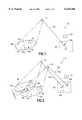
- FIG. 1depicts the geometry of a radio frequency map generating system in accordance with this invention.
- FIG. 2depicts the geometry of a radio frequency map generating system comprising at least two satellites in accordance with this invention.
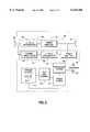
- FIG. 5is a block diagram depicting processing functions to be used by a gateway for reallocating operating frequencies of user terminals.
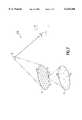
- FIG. 7depicts the gateway/satellite/user terminal geometry for resource allocation calculations.
- MSSmobile satellite service
- Such a mapis useful for operators of present and future RF systems, both terrestrial and satellite-based, in determining techniques for mitigation of RFI.
- the defined radio frequency mapis used to optimize resource allocation in the MSS system.
- Such an RF mapcould also be used by standards bodies for determining compliance with local or global RF emissions standards.
- the global RF mapscould be of use to physical and environmental scientists. At present, information on RFI in various frequency bands is either unknown and/or localized, especially in some countries where the regulatory and licensing procedures for RF systems are less strict.
- a presently preferred embodiment of an RF mapping systememploys a constellation of low earth orbit (LEO) satellites that communicate through one or more terrestrial gateways.
- LEOlow earth orbit
- the individual gatewaysare each bidirectionally coupled to one or more terrestrial communication systems, such as the local Public Switched Telephone Network (PSTN), as well as to private and public data and voice networks.
- PSTNPublic Switched Telephone Network
- the inventionenables RF mapping of the 1610-1626.5 MHz frequency band using the C-band feederlink.
- the same principlecan be applied to RF mapping of the world using other GSO or non-GSO satellite constellations operating in other frequency bands, using feederlinks in the same or other frequency bands.
- the C-band interference 34 corresponding to the feederlink signal 22a frequencycan be estimated by attaching a spectrum analyzer to the gateway 20 receiving antenna 20a when the antenna 20a is not pointing at the satellite 14. After subtracting the noise and feederlink signal 22a contributions, the remainder may be assumed to be due only to L-band emitters 30 in the satellite beam 26.
- the system 10When the system 10 is fully operational, that is during normal operations, it may not be possible to find a 1.23 MHz channel that is unoccupied by user terminal 32 traffic. In this case, it is possible to calculate the contribution of the desired user terminal 32 traffic to the total uplink power and subtract it out.
- the contribution of the user terminal 32 traffic at each time instantis calculated at the gateway 20 from operating system parameters available to the gateway 20, and the number and location of users represented by the user terminals 32 being served by the gateway 20.
- User terminal 32 locationis obtained as part of the position location service that will be offered by most of the MSS operators.
- the signals associated with each user terminal 32can be subtracted from the initial C-band power measurement to reveal the existence of L-band emitters 30 in a given beam 26.
- the system 110comprises at least two non-GSO satellites. More specifically, the satellite 14 and a satellite 12 of a non-GSO constellation are shown.
- the satellite 14has an operational zone of coverage defined by the L-band footprint 18a.
- the satellite 12has an operational zone of coverage defined by an L-band footprint 18b.
- the gateway 20comprises several high-gain antennas such as the antenna 20a and an antenna 20b. Each antenna tracks a separate feederlink signal 22 from satellites 12 and 14.
- the feederlink signal 22acorresponds to a signal transmitted from the satellite 14 to the antenna 20a.
- the external interference 34 at C-bandthat is picked up by the gateway 20 antenna (20a, 20b) sidelobes. Because of the directivity of the gateway 20 antennas 20a, 20b, the level of C-band interference 34 picked up by the antennas 20a, 20b is typically small relative to the feederlink energy.
- each satellite 12, 14typically has many beams 26 that cover a portion of the Earth's surface, a certain amount of localization of the interference emitter 30 occurs immediately. Further narrowing of the position of the interference emitter 30, however, can be obtained by correlating, at the gateway 20 or a system network control center, the received power from the satellites 12, 14 of the system 110, given that the gateway 20 knows the satellite 12, 14 antenna patterns at L-band and C-band. In effect, this is a form of triangulation to more accurately determine the location of the interferer emitter 30. As the satellites 12, 14 move they cover different areas of the surface of the Earth.
- the gateway 20Since the gateway 20 has knowledge of the satellite 12, 14 locations and the positions of the user terminals 32, as discussed above, it is possible to map the area swept by the satellite 12, 14 beams 26, determining the location of the interferer emitter 30 more accurately. By making measurements in different L-band channels, interferer emitters 30 in the entire 16.5 MHz band can be mapped.
- the payload 40comprises a multi-beam L-band antenna 42, a C-band antenna 44 and two transponders: a first transponder 46 suitable for the MSS function and a second transponder 48.
- the first transponder 46is used to obtain an RF map of the world at 1610-1626.5 MHz and further comprises an L-to-C upconverter 50 and a corresponding power amplifier 52.
- the second transponder 48is tunable in the L-band and thus can be used to monitor and map the rest of the L-band frequency range.
- the second transponder 48comprises a tunable L-band filter 54, an L-to-C upconverter 56 and a corresponding power amplifier 58. Since no L-band signal is being emitted by the transponder 48 in the remaining portion of the L-band, no regulatory license is needed to modify the MSS payload by adding the transponder 48 to the satellite 12, 14.
- the incoming L-band signalsare amplified by the multi-beam L-band antenna 42 and the feederlink signals 22 are transmitted by the low-gain global-coverage C-band antenna 44.
- the feederlink 22 sub-band on which the satellite 12, 14 transmitsis different for each uplink L-band beam.
- transponder 48with a tunable filter 54a (not shown) which passes frequencies of other bands of interest or to add another transponder 48a (not shown) to the satellite 12, 14 payload, tunable to any other uplink frequency while using the same satellite-gateway frequency as the example system 110, and map the RFI in that uplink frequency band.
- a telemetry (TLM) and control system 45can be used to direct the satellite antennas 42, 44 in a pattern so as to isolate the interference source 30.
- a conventional power system 51provides operating power for all of the illustrated satellite components.
- FIG. 4a block diagram depicting processing functions to be used by each gateway 20 for generating an RF interference map in accordance with this invention is shown.
- C-band poweris measured in the received feederlink signal 22 which corresponds to a particular beam 26 of a particular L-band footprint 18.
- the gateway 20obtains various system parameter information from which a power component related to thermal noise can be subtracted in a step 66 from the measured C-band power resulting from the step 62.
- the C-band power spectrum datais obtained with the aid of a spectrum analyzer or other suitable device, as previously discussed, and then subtracted from the result of the step 66 in a step 70.
- user terminal 32 data representing known locations of currently active user terminals 32is obtained in a step 72 and subtracted from the resultant of the step 70 in a step 74.
- the resulting power measurement 80ais provided to a step 80 as a resultant from the step 74. It is important to note that the order of the steps 66, 70, and 74 may be interchanged since they are not dependent on the determination of each other. Thus, the step 70 could be performed subsequent to the step 62 and prior to the step 66.
- a step 76satellite 12
- 14 position information and corresponding beam 26 contour dataare obtained providing an input 80b to the step 80.
- satellite information from several satellites, regarding areas where the L-band footprint 18 of at least two satellites overlapis correlated and provided as an input 80c to the step 80.
- undesirable L-band emitter 30 signal power and location informationis determined for every L-band emitter in current beam 26 and then stored in an RFI database in a step 82.
- the steps 62 through 80further define a unified step 96 shown in dashed line.
- the RFI databasedefines a radio frequency map, more specifically a radio frequency interference map, wherein L-band interference sources may be identified as to terrestrial location.
- the system 10uses distributed control, where a number of gateways 20 communicate as a single unit and control a number of satellites, some of these functions can be performed at each gateway 20. However, if the network architecture uses central control, these functions could be performed at the network control center (not shown). In any case, the system 10 maintains statistics on the interference emitter 30 power it received in each channel C in each beam 26 at each time-step, typically a minute. By compiling, at a central location, the history of data from different gateways 20, high resolution, spatial and temporal, world-wide radio frequency spectrum maps can be generated.
- the gateway 20 and/or the central network control center of an MSS systemcan use the RFI map defined by the step 82 to optimize its use of limited system resources, such as frequencies and satellite power.
- knowledge of external interference as a function of time and spacecan be used by the gateway 20 or network control center to assign mobile and handheld user terminals 32a to frequency channels that have relatively low interference, and fixed user terminals 32b (e.g. phone booths on remote roads or villages that make use of the MSS) to those with higher interference.
- fixed user terminals 32be.g. phone booths on remote roads or villages that make use of the MSS
- Thisis useful because mobile and handheld user terminals 32a typically have lower power transmitters and lower gain antennas than fixed user terminals 32b. Therefore fixed user terminals 32b can operate at the higher EIRP levels needed to overcome the interference in noisier channels.
- Such an assignment of frequency channelsenables the system 10 to serve a larger total number of user terminals 32.
- Reallocation of user terminal 32 frequency channels Ccan be achieved predictably or dynamically. If the L-band emitter 30 signal interference is found to be predictable, channel reallocation for any given time period may be provided in advance. For example, if an L-band emitter 30 is consistently active during a specific daily time period, reallocation of channel frequencies can be made automatic for this time period. If the L-band emitter 30 signal interference is not predictable, a dynamic channel reallocation of users is possible at the gateway 20 using sufficiently fast processors. Also, note again that the use of this method is not restricted to CDMA systems. This method could be used for time division multiple access (TDMA) systems, and for Frequency Division, Multiple Access (FDMA) systems.
- TDMAtime division multiple access
- FDMAFrequency Division, Multiple Access
- gateway 20 procedures for an examplary MSS system 90 using the radio frequency interference database stored in the step 82 for channel c frequency reallocationis shown.
- the C-band signal received at the gateway 20is demodulated in the gateway 20 RF equipment during a step 92.
- the baseband output from this equipmentis formatted in a first interface unit during a step 94 and then provided as an input 100a to a processor.
- the processorperforms the algorithms for calculating the radio frequency interference as shown in FIG. 4 and provides the calculation as an input 100c to the processor.
- the processorperforms a desired technique for resource allocation.
- the processor 100generates and stores the RFI database in the step 82 as previously discussed.
- the processor 100later uses the stored RFI database 82 as an input 100b along with the resource allocation algorithms of the step 98, as an input 100d, to determine the channel frequency reallocation.
- a second interface unitreformats the processor output 100e and converts it into a user terminal 32 frequency channel assignment message in a step 104.
- the frequency channel assignment messageis provided to a baseband-to-RF converter in a step 106 and radiated by the gateway 20 antennas, finally reaching the user terminal 32.
- the UT(s)shift their transmitter frequencies accordingly.
- This scheme for frequency reallocation after RFI mappingapplies to any system that divides its allocated bandwidth into multiple frequency channels; each of these channels may accommodate signals from multiple user terminals 32 by using either CDMA, TDMA, or any other multiple access scheme.
- FIG. 7shows the system 210 comprising a gateway g, a satellite s, an L-band beam b, and a number of traffic concentrator gridpoints k.
- Each gridpoint kis further comprised of at least one user terminal 32.
- the system 210can be modeled by covering the world with a set of gridpoints k, and assuming user terminals 32 to be grouped into the traffic concentrations at each gridpoint k.
- FIG. 7shows user terminals 32 located at gridpoints k covered by a single beam b of a satellite s, and the gateway g processing the signal from this beam b of the satellite s.
- the MSS system bandwidth of 1610.7-1625.8 MHz in the example system 210is divided into the 13 channels C, each of them 1.23 MHz wide. Each of these 13 channels C is reused in each L-band beam of the satellite, as shown in FIG. 6.
- Several user terminals 32are assigned to each channel C and share the channel using CDMA.
- a gateway gsends power control messages to each user terminal 32 to set its transmit power to just equal the value required to maintain a particular signal-to-noise-plus-interference ratio (SNIR) given by E b /N t .reqd.
- SNIRsignal-to-noise-plus-interference ratio
- the gateway g and/or the network control centerperforms the resource allocation by performing a time-step by time-step simulation of the entire system 210.
- y kcthe transmitter output power of a user terminal 32 at the k th gridpoint traffic concentrator in a channel c.
- L-band user terminal 32transmit power limit:
- w kcis the number of circuits at traffic concentrator gridpoint k to be supported by the channel c on the return link
- P xmtuseris the user transmit power limit, which is about 1 or 2 watts for hand-held devices, approximately 3 watts for mobile devices, and approximately 10 watts for fixed terminals (all of these values are exemplary).
- N ois the total thermal noise due to both uplink and downlink paths, measured at the gateway receiver;
- L path ksfree space path loss from traffic concentration k to satellite s
- L misc ksthe miscellaneous path loss (antenna pointing, polarization loss) from traffic concentration k to satellite s;
- L path sgfree space path loss from satellite s to gateway g;
- L misc sgthe miscellaneous path loss (tracking, polarization and rain loss) from satellite s towards gateway g;
- T bitbit time, which is the reciprocal of data rate
- T chipchip time, which is the reciprocal of chip rate (1.23 MHz).
- the satellite s antenna gain for beam bis large for gridpoints k' close to the peak of the beam b, and is decreased at gridpoints k' that are further away from the beam b peak; for generality, the beam b is assumed to have non-zero gain at all gridpoints k visible to the satellite s.
- the resource allocation algorithms in the gateway ginvolve, at each time t, solving for the y kc that satisfy Eqs. (1), (4) and all other constraints using techniques such as iteration, or numerical methods or linear programming; the objective of the resource allocation is usually to maximize the sum of all user terminals 32 served, expressed by ##EQU3## which represents the system capacity.
- One of the challenges in the resource allocationis to assign user terminals 32 to channels C in an efficient manner.
- Eq. (4)shows, users in channels that have high external interference I ext .c need higher transmit power values y kc than those in channels C with lower external interference I ext .c
- one preferred channel assignment rule at the gateway gis to assign fixed user terminals 32b to those channels that it knows to have high external interference I ext .c, and to reserve the channels with low external interference I ext .c for mobile and handheld user terminals 32a.
- map generating system 10could also be used to map specific areas of space by simply directing a receiving antenna of the satellite 14 at the desired area and providing a transponder as part of the satellite 14 with the appropriate tuning capabilities. Additionally, while the method disclosed can be performed by a single satellite, a GSO or non-GSO satellite, the method is not limited to a specific number of satellites, GSO or non-GSO satellites, or a combination of both.
Landscapes
- Engineering & Computer Science (AREA)
- Physics & Mathematics (AREA)
- Astronomy & Astrophysics (AREA)
- Aviation & Aerospace Engineering (AREA)
- General Physics & Mathematics (AREA)
- Computer Networks & Wireless Communication (AREA)
- Signal Processing (AREA)
- Radio Relay Systems (AREA)
- Mobile Radio Communication Systems (AREA)
- Monitoring And Testing Of Transmission In General (AREA)
Abstract
Description
∀k,c:y.sub.kc /w.sub.kc ≦P.sub.xmtuser
Claims (20)
Priority Applications (1)
| Application Number | Priority Date | Filing Date | Title |
|---|---|---|---|
| US09/169,407US6125260A (en) | 1997-04-29 | 1998-10-09 | System for generating and using global radio frequency maps |
Applications Claiming Priority (2)
| Application Number | Priority Date | Filing Date | Title |
|---|---|---|---|
| US08/840,370US5905943A (en) | 1997-04-29 | 1997-04-29 | System for generating and using global radio frequency maps |
| US09/169,407US6125260A (en) | 1997-04-29 | 1998-10-09 | System for generating and using global radio frequency maps |
Related Parent Applications (1)
| Application Number | Title | Priority Date | Filing Date |
|---|---|---|---|
| US08/840,370ContinuationUS5905943A (en) | 1997-04-29 | 1997-04-29 | System for generating and using global radio frequency maps |
Publications (1)
| Publication Number | Publication Date |
|---|---|
| US6125260Atrue US6125260A (en) | 2000-09-26 |
Family
ID=25282187
Family Applications (2)
| Application Number | Title | Priority Date | Filing Date |
|---|---|---|---|
| US08/840,370Expired - Fee RelatedUS5905943A (en) | 1997-04-29 | 1997-04-29 | System for generating and using global radio frequency maps |
| US09/169,407Expired - Fee RelatedUS6125260A (en) | 1997-04-29 | 1998-10-09 | System for generating and using global radio frequency maps |
Family Applications Before (1)
| Application Number | Title | Priority Date | Filing Date |
|---|---|---|---|
| US08/840,370Expired - Fee RelatedUS5905943A (en) | 1997-04-29 | 1997-04-29 | System for generating and using global radio frequency maps |
Country Status (8)
| Country | Link |
|---|---|
| US (2) | US5905943A (en) |
| JP (1) | JPH10336091A (en) |
| KR (1) | KR19980081679A (en) |
| AU (1) | AU6775298A (en) |
| CA (1) | CA2234758A1 (en) |
| ID (1) | ID20206A (en) |
| TW (1) | TW392394B (en) |
| WO (1) | WO1998049787A1 (en) |
Cited By (44)
| Publication number | Priority date | Publication date | Assignee | Title |
|---|---|---|---|---|
| US20020123343A1 (en)* | 2000-12-29 | 2002-09-05 | Globalstar L.P. | Method and apparatus providing suppression of system access by use of confidence polygons, volumes and surfaces in a mobile satellite system |
| US20020126770A1 (en)* | 2001-03-09 | 2002-09-12 | Behrouz Pourseyed | Method and system for acquiring narrowband channel information over a wideband channel receiver |
| US6704546B1 (en)* | 1998-04-10 | 2004-03-09 | Nortel Matra Cellular | Method and apparatus for allocation of a transmission frequency within a given frequency spectrum |
| US20040091033A1 (en)* | 2002-10-25 | 2004-05-13 | Chen Emest C. | On-line phase noise measurement for layered modulation |
| US6763009B1 (en)* | 1999-12-03 | 2004-07-13 | Lucent Technologies Inc. | Down-link transmission scheduling in CDMA data networks |
| US20040157553A1 (en)* | 2001-02-26 | 2004-08-12 | Christophe Levallet | Satellite telecommunication method and system and base station for one such system |
| US20040204026A1 (en)* | 2003-04-09 | 2004-10-14 | Ar Card | Method, apparatus and system of configuring a wireless device based on location |
| US6859652B2 (en) | 2000-08-02 | 2005-02-22 | Mobile Satellite Ventures, Lp | Integrated or autonomous system and method of satellite-terrestrial frequency reuse using signal attenuation and/or blockage, dynamic assignment of frequencies and/or hysteresis |
| US6892068B2 (en) | 2000-08-02 | 2005-05-10 | Mobile Satellite Ventures, Lp | Coordinated satellite-terrestrial frequency reuse |
| US20070109987A1 (en)* | 2005-11-16 | 2007-05-17 | Berkana Wirless, Inc. | WCDMA device and method for discontinuous reception for power saving in idle mode and flexible monitoring of neighboring cells |
| US20070116156A1 (en)* | 2001-04-27 | 2007-05-24 | Chen Ernest C | Layered modulation for digital signals |
| EP1529347A4 (en)* | 2002-07-03 | 2007-10-31 | Directv Group Inc | METHOD AND APPARATUS FOR LAYERED MODULATION |
| US20080014948A1 (en)* | 2006-07-14 | 2008-01-17 | Lgc Wireless, Inc. | System for and method of for providing dedicated capacity in a cellular network |
| US7418060B2 (en) | 2002-07-01 | 2008-08-26 | The Directv Group, Inc. | Improving hierarchical 8PSK performance |
| US7423987B2 (en) | 2001-04-27 | 2008-09-09 | The Directv Group, Inc. | Feeder link configurations to support layered modulation for digital signals |
| US7426243B2 (en) | 2001-04-27 | 2008-09-16 | The Directv Group, Inc. | Preprocessing signal layers in a layered modulation digital signal system to use legacy receivers |
| US7426246B2 (en) | 2001-04-27 | 2008-09-16 | The Directv Group, Inc. | Dual layer signal processing in a layered modulation digital signal system |
| US20080232328A1 (en)* | 2007-03-23 | 2008-09-25 | Stefan Scheinert | Localization of a mobile device in distributed antenna communications system |
| US7469019B2 (en) | 2001-04-27 | 2008-12-23 | The Directv Group, Inc. | Optimization technique for layered modulation |
| US7471735B2 (en) | 2001-04-27 | 2008-12-30 | The Directv Group, Inc. | Maximizing power and spectral efficiencies for layered and conventional modulations |
| US20090005096A1 (en)* | 2007-06-26 | 2009-01-01 | Stefan Scheinert | Distributed antenna communications system |
| US7474710B2 (en) | 2002-10-25 | 2009-01-06 | The Directv Group, Inc. | Amplitude and phase matching for layered modulation reception |
| US7483505B2 (en) | 2001-04-27 | 2009-01-27 | The Directv Group, Inc. | Unblind equalizer architecture for digital communication systems |
| US20090061940A1 (en)* | 2007-08-31 | 2009-03-05 | Stefan Scheinert | System for and method of configuring distributed antenna communications system |
| US7502429B2 (en) | 2003-10-10 | 2009-03-10 | The Directv Group, Inc. | Equalization for traveling wave tube amplifier nonlinearity measurements |
| US7502430B2 (en) | 2001-04-27 | 2009-03-10 | The Directv Group, Inc. | Coherent averaging for measuring traveling wave tube amplifier nonlinearity |
| US7512189B2 (en) | 2001-04-27 | 2009-03-31 | The Directv Group, Inc. | Lower complexity layered modulation signal processor |
| US7529312B2 (en) | 2002-10-25 | 2009-05-05 | The Directv Group, Inc. | Layered modulation for terrestrial ATSC applications |
| US7583728B2 (en) | 2002-10-25 | 2009-09-01 | The Directv Group, Inc. | Equalizers for layered modulated and other signals |
| US7639759B2 (en) | 2001-04-27 | 2009-12-29 | The Directv Group, Inc. | Carrier to noise ratio estimations from a received signal |
| US20100093270A1 (en)* | 2008-10-09 | 2010-04-15 | Jamie Bass | Signal transmission surveillance system |
| FR2942090A1 (en)* | 2009-02-11 | 2010-08-13 | Eutelsat | TELECOMMUNICATION NETWORK |
| US7778365B2 (en) | 2001-04-27 | 2010-08-17 | The Directv Group, Inc. | Satellite TWTA on-line non-linearity measurement |
| US7792488B2 (en) | 2000-12-04 | 2010-09-07 | Atc Technologies, Llc | Systems and methods for transmitting electromagnetic energy over a wireless channel having sufficiently weak measured signal strength |
| US7817958B2 (en) | 2006-12-22 | 2010-10-19 | Lgc Wireless Inc. | System for and method of providing remote coverage area for wireless communications |
| US7822154B2 (en) | 2001-04-27 | 2010-10-26 | The Directv Group, Inc. | Signal, interference and noise power measurement |
| US7848770B2 (en) | 2006-08-29 | 2010-12-07 | Lgc Wireless, Inc. | Distributed antenna communications system and methods of implementing thereof |
| US20110140884A1 (en)* | 2009-10-23 | 2011-06-16 | Globalstar, Inc. | Simplex Personal and Asset Tracker |
| US8005035B2 (en) | 2001-04-27 | 2011-08-23 | The Directv Group, Inc. | Online output multiplexer filter measurement |
| US8676121B1 (en) | 2011-05-31 | 2014-03-18 | Globalstar, Inc. | Method and apparatus for transmitting message from short-range wireless device over a satellite network |
| US9287911B1 (en)* | 2012-08-22 | 2016-03-15 | Sprint Spectrum L.P. | Mitigating signal interference |
| US9619977B2 (en) | 2015-08-27 | 2017-04-11 | Trident Holding, LLC | Deployable beacon |
| US9733338B1 (en)* | 2012-10-08 | 2017-08-15 | The Boeing Company | Single satellite geolocation systems and methods |
| US20170371040A1 (en)* | 2016-06-15 | 2017-12-28 | Hughes Network Systems, Llc | Apparatus and methods for interference mitigation by satellite networks |
Families Citing this family (21)
| Publication number | Priority date | Publication date | Assignee | Title |
|---|---|---|---|---|
| US6745028B1 (en)* | 1997-07-16 | 2004-06-01 | Ico Services Limited | Satellite mobile telephone cell departure prediction |
| US5974315A (en)* | 1997-09-03 | 1999-10-26 | Lockheed Martin Corporation | Spacecraft cellular communication system |
| US6101385A (en) | 1997-10-09 | 2000-08-08 | Globalstar L.P. | Satellite communication service with non-congruent sub-beam coverage |
| KR100696056B1 (en)* | 1999-11-05 | 2007-03-15 | 주식회사 케이티 | Satellite communication network monitoring method to secure satellite communication service quality |
| WO2001037450A1 (en)* | 1999-11-16 | 2001-05-25 | Comsat Corporation | Distributed control architecture for mobile systems with overlapping service coverage regions |
| US6483865B1 (en)* | 2000-04-13 | 2002-11-19 | The Boeing Company | Wireless interface for electronic devices located in enclosed spaces |
| US20020044614A1 (en)* | 2000-09-12 | 2002-04-18 | Molnar Karl James | Methods and systems for reducing interference using co-channel interference mapping |
| US20050085186A1 (en)* | 2001-05-08 | 2005-04-21 | William Sandrin | Method and apparatus for measuring adjacent satellite interference |
| IL168150A (en)* | 2005-04-20 | 2011-02-28 | Elta Systems Ltd | System and method for processing satellite communication data |
| US8463178B2 (en) | 2006-06-05 | 2013-06-11 | Globalstar, Inc. | Handover between ATC and satellite component of an integrated MSS/ATC system |
| EP2228916A1 (en)* | 2009-03-12 | 2010-09-15 | Astrim Limited | Interference removal |
| KR101218334B1 (en)* | 2010-12-29 | 2013-01-21 | 숭실대학교산학협력단 | Apparatus and method for providing wireless connection in smart utility network using white space |
| US8594572B1 (en)* | 2011-06-16 | 2013-11-26 | The United States Of America As Represented By The Secretary Of The Navy | Wireless electric power transmission through wall |
| KR20130104337A (en)* | 2012-03-13 | 2013-09-25 | 한국전자통신연구원 | Apparatus and method for allocating resource in multi-beam satellite communication |
| JP6091595B2 (en) | 2012-03-19 | 2017-03-08 | ロバート ケイ. バックル, | Apparatus, method and system for integrating mobile and satellite telephone services |
| US9918267B2 (en) | 2013-07-03 | 2018-03-13 | Blackberry Limited | Mitigation of radio interference and thermal issues using radio access technology selection |
| EP2822338B1 (en)* | 2013-07-03 | 2017-11-22 | BlackBerry Limited | Mitigation of radio interference and thermal issues using radio access technology selection |
| JP6543276B2 (en) | 2014-03-07 | 2019-07-10 | グローバルスター, インコーポレイテッド | Cell tower function with satellite access to allow cell devices to roam over a satellite network |
| US9960836B2 (en)* | 2014-05-19 | 2018-05-01 | L-3 Technologies, Inc. | Method and system for satellite using multifunctional motherboard |
| CN112272381B (en)* | 2020-10-22 | 2022-08-30 | 大连大学 | Satellite network task deployment method and system |
| CN112698112B (en)* | 2021-03-23 | 2021-06-01 | 中国人民解放军国防科技大学 | Electromagnetic spectrum map construction method and device, computer equipment and storage medium |
Citations (32)
| Publication number | Priority date | Publication date | Assignee | Title |
|---|---|---|---|---|
| US32905A (en)* | 1861-07-23 | Daniel B Waite | Watch and socket rim | |
| USRE32905E (en) | 1980-10-20 | 1989-04-11 | Equatorial Communications Company | Satellite communications system and apparatus |
| US4901307A (en)* | 1986-10-17 | 1990-02-13 | Qualcomm, Inc. | Spread spectrum multiple access communication system using satellite or terrestrial repeaters |
| WO1990013186A1 (en)* | 1989-04-25 | 1990-11-01 | Geostar Corporation | Communication system employing multiple relay satellites operating on common downlink frequency |
| EP0421698A2 (en)* | 1989-10-02 | 1991-04-10 | Motorola, Inc. | Method of predicting cell-to-cell hand-offs for a satellite cellular communications system |
| US5010317A (en)* | 1989-11-30 | 1991-04-23 | Motorola, Inc. | Satellite based simulcast paging system |
| WO1991009473A1 (en)* | 1989-12-14 | 1991-06-27 | Motorola, Inc. | Satellite based acknowledge-back paging system |
| US5073900A (en)* | 1990-03-19 | 1991-12-17 | Mallinckrodt Albert J | Integrated cellular communications system |
| US5081703A (en)* | 1990-06-27 | 1992-01-14 | Pactel Corporation | Satellite mobile communication system for rural service areas |
| JPH0454025A (en)* | 1990-06-22 | 1992-02-21 | Kokusai Denshin Denwa Co Ltd <Kdd> | Satellite line demand allocation device |
| JPH04104526A (en)* | 1990-08-24 | 1992-04-07 | Kokusai Denshin Denwa Co Ltd <Kdd> | Satellite channel demand assigning device |
| US5109390A (en)* | 1989-11-07 | 1992-04-28 | Qualcomm Incorporated | Diversity receiver in a cdma cellular telephone system |
| US5119225A (en)* | 1988-01-18 | 1992-06-02 | British Aerospace Public Limited Company | Multiple access communication system |
| WO1993009613A1 (en)* | 1991-10-28 | 1993-05-13 | Calling Communications Corporation | Satellite communication system |
| US5216427A (en)* | 1990-11-01 | 1993-06-01 | California Institute Of Technology | Land-mobile satellite communication system |
| US5233626A (en)* | 1992-05-11 | 1993-08-03 | Space Systems/Loral Inc. | Repeater diversity spread spectrum communication system |
| US5239671A (en)* | 1990-11-13 | 1993-08-24 | Pagemart, Inc. | Simulcast satellite paging system with provision for signal interruption |
| US5265119A (en)* | 1989-11-07 | 1993-11-23 | Qualcomm Incorporated | Method and apparatus for controlling transmission power in a CDMA cellular mobile telephone system |
| US5303286A (en)* | 1991-03-29 | 1994-04-12 | Space Systems/Loral, Inc. | Wireless telephone/satellite roaming system |
| US5410728A (en)* | 1988-10-28 | 1995-04-25 | Motorola, Inc. | Satellite cellular telephone and data communication system |
| US5422647A (en)* | 1993-05-07 | 1995-06-06 | Space Systems/Loral, Inc. | Mobile communication satellite payload |
| US5433726A (en)* | 1991-04-22 | 1995-07-18 | Trw Inc. | Medium-earth-altitude satellite-based cellular telecommunications system |
| US5439190A (en)* | 1991-04-22 | 1995-08-08 | Trw Inc. | Medium-earth-altitude satellite-based cellular telecommunications |
| US5446756A (en)* | 1990-03-19 | 1995-08-29 | Celsat America, Inc. | Integrated cellular communications system |
| US5448623A (en)* | 1991-10-10 | 1995-09-05 | Space Systems/Loral, Inc. | Satellite telecommunications system using network coordinating gateways operative with a terrestrial communication system |
| US5566354A (en)* | 1994-09-26 | 1996-10-15 | Sehloemer; Jerry R. | System and method for channel assignment in a satellite telephone system |
| US5590395A (en)* | 1993-11-10 | 1996-12-31 | Motorola, Inc. | Satellite cellular network resource management method and apparatus |
| US5619525A (en)* | 1995-06-06 | 1997-04-08 | Globalstar L.P. | Closed loop power control for low earth orbit satellite communications system |
| US5736959A (en)* | 1991-10-28 | 1998-04-07 | Teledesic Corporation | Earth-fixed cell beam management for satellite communication system using dielectic lens-focused scanning beam antennas |
| EP0837569A2 (en)* | 1996-10-21 | 1998-04-22 | Globalstar L.P. | Multiple satellite fade attenuation control system |
| US5768684A (en)* | 1994-03-04 | 1998-06-16 | Motorola, Inc. | Method and apparatus for bi-directional power control in a digital communication system |
| US5875180A (en)* | 1997-02-06 | 1999-02-23 | Globalstar L.P. | Satellite telephone interference avoidance system |
Family Cites Families (1)
| Publication number | Priority date | Publication date | Assignee | Title |
|---|---|---|---|---|
| US5768864A (en)* | 1996-05-10 | 1998-06-23 | Chang; Robert | Saddle girth with protective cover |
- 1997
- 1997-04-29USUS08/840,370patent/US5905943A/ennot_activeExpired - Fee Related
- 1998
- 1998-03-24WOPCT/US1998/005914patent/WO1998049787A1/enunknown
- 1998-03-24AUAU67752/98Apatent/AU6775298A/ennot_activeAbandoned
- 1998-03-30TWTW087104709Apatent/TW392394B/enactive
- 1998-04-16CACA002234758Apatent/CA2234758A1/ennot_activeAbandoned
- 1998-04-23KRKR1019980014599Apatent/KR19980081679A/ennot_activeCeased
- 1998-04-27IDIDP980627Apatent/ID20206A/enunknown
- 1998-04-30JPJP10120878Apatent/JPH10336091A/enactivePending
- 1998-10-09USUS09/169,407patent/US6125260A/ennot_activeExpired - Fee Related
Patent Citations (35)
| Publication number | Priority date | Publication date | Assignee | Title |
|---|---|---|---|---|
| US32905A (en)* | 1861-07-23 | Daniel B Waite | Watch and socket rim | |
| USRE32905E (en) | 1980-10-20 | 1989-04-11 | Equatorial Communications Company | Satellite communications system and apparatus |
| USRE32905F1 (en) | 1980-10-20 | 1992-11-10 | Satellite communications system and apparatus | |
| US4901307A (en)* | 1986-10-17 | 1990-02-13 | Qualcomm, Inc. | Spread spectrum multiple access communication system using satellite or terrestrial repeaters |
| US5119225A (en)* | 1988-01-18 | 1992-06-02 | British Aerospace Public Limited Company | Multiple access communication system |
| US5410728A (en)* | 1988-10-28 | 1995-04-25 | Motorola, Inc. | Satellite cellular telephone and data communication system |
| WO1990013186A1 (en)* | 1989-04-25 | 1990-11-01 | Geostar Corporation | Communication system employing multiple relay satellites operating on common downlink frequency |
| EP0421698A2 (en)* | 1989-10-02 | 1991-04-10 | Motorola, Inc. | Method of predicting cell-to-cell hand-offs for a satellite cellular communications system |
| US5109390A (en)* | 1989-11-07 | 1992-04-28 | Qualcomm Incorporated | Diversity receiver in a cdma cellular telephone system |
| US5265119A (en)* | 1989-11-07 | 1993-11-23 | Qualcomm Incorporated | Method and apparatus for controlling transmission power in a CDMA cellular mobile telephone system |
| US5010317A (en)* | 1989-11-30 | 1991-04-23 | Motorola, Inc. | Satellite based simulcast paging system |
| WO1991009473A1 (en)* | 1989-12-14 | 1991-06-27 | Motorola, Inc. | Satellite based acknowledge-back paging system |
| US5073900A (en)* | 1990-03-19 | 1991-12-17 | Mallinckrodt Albert J | Integrated cellular communications system |
| US5446756A (en)* | 1990-03-19 | 1995-08-29 | Celsat America, Inc. | Integrated cellular communications system |
| US5339330A (en)* | 1990-03-19 | 1994-08-16 | David D. Otten | Integrated cellular communications system |
| JPH0454025A (en)* | 1990-06-22 | 1992-02-21 | Kokusai Denshin Denwa Co Ltd <Kdd> | Satellite line demand allocation device |
| US5081703A (en)* | 1990-06-27 | 1992-01-14 | Pactel Corporation | Satellite mobile communication system for rural service areas |
| JPH04104526A (en)* | 1990-08-24 | 1992-04-07 | Kokusai Denshin Denwa Co Ltd <Kdd> | Satellite channel demand assigning device |
| US5216427A (en)* | 1990-11-01 | 1993-06-01 | California Institute Of Technology | Land-mobile satellite communication system |
| US5239671A (en)* | 1990-11-13 | 1993-08-24 | Pagemart, Inc. | Simulcast satellite paging system with provision for signal interruption |
| US5303286A (en)* | 1991-03-29 | 1994-04-12 | Space Systems/Loral, Inc. | Wireless telephone/satellite roaming system |
| US5439190A (en)* | 1991-04-22 | 1995-08-08 | Trw Inc. | Medium-earth-altitude satellite-based cellular telecommunications |
| US5433726A (en)* | 1991-04-22 | 1995-07-18 | Trw Inc. | Medium-earth-altitude satellite-based cellular telecommunications system |
| US5551624A (en)* | 1991-04-22 | 1996-09-03 | Trw Inc. | Medium-earth-altitude satellite-based cellular telecommunications |
| US5448623A (en)* | 1991-10-10 | 1995-09-05 | Space Systems/Loral, Inc. | Satellite telecommunications system using network coordinating gateways operative with a terrestrial communication system |
| US5736959A (en)* | 1991-10-28 | 1998-04-07 | Teledesic Corporation | Earth-fixed cell beam management for satellite communication system using dielectic lens-focused scanning beam antennas |
| WO1993009613A1 (en)* | 1991-10-28 | 1993-05-13 | Calling Communications Corporation | Satellite communication system |
| US5233626A (en)* | 1992-05-11 | 1993-08-03 | Space Systems/Loral Inc. | Repeater diversity spread spectrum communication system |
| US5422647A (en)* | 1993-05-07 | 1995-06-06 | Space Systems/Loral, Inc. | Mobile communication satellite payload |
| US5590395A (en)* | 1993-11-10 | 1996-12-31 | Motorola, Inc. | Satellite cellular network resource management method and apparatus |
| US5768684A (en)* | 1994-03-04 | 1998-06-16 | Motorola, Inc. | Method and apparatus for bi-directional power control in a digital communication system |
| US5566354A (en)* | 1994-09-26 | 1996-10-15 | Sehloemer; Jerry R. | System and method for channel assignment in a satellite telephone system |
| US5619525A (en)* | 1995-06-06 | 1997-04-08 | Globalstar L.P. | Closed loop power control for low earth orbit satellite communications system |
| EP0837569A2 (en)* | 1996-10-21 | 1998-04-22 | Globalstar L.P. | Multiple satellite fade attenuation control system |
| US5875180A (en)* | 1997-02-06 | 1999-02-23 | Globalstar L.P. | Satellite telephone interference avoidance system |
Non-Patent Citations (32)
| Title |
|---|
| "A Communication Technique for Multipath Channels", R. Price, Proceedings of the IR, Mar. 1958, pp. 555-570. |
| "An Integrated Satellite-Cellular Land Mobile System for Europe", E. Del Re, University of Florence, Dept. of Electronics Engineering, italy, Sep. 21, 1989. |
| "Digital Network Oriented Mobile Radio Satellite System as an Integrated Part of The GSM Cellular Radio System in Europe", P. Dondl, Deutsch Bundespost/Fernmeldetechniches Zentralmt/Darmstadt, Fed. Rep. Germ. Sep. 21, 1989. |
| "Increased Capacity Using CDMA for Mobile Satellite Communication", K. Gilhousen et al., IEEE Journal on Selected Areas in Communications, vol. 8, No. 4, May 1990, pp. 503-514. |
| "Iridium: Key to Worldwide Cellular Communications", J. Foley, Telecommunications, Oct. 1991, pp. 23-28. |
| "Software Implementation of a PN Spread Spectrum Receiver to Accommodate Dynamics", C. Cahn et al., IEEE Trans. on Comm., vol. COM-25, No. 8, Aug. 1977. |
| "The IridiumTM1 System A Revolutionary Satellite Communications System Developed with Innovative Applications of Technology", D. Sterling et al., IEEE, Milcom 1991, Nov. 4-7. |
| "The OmniTRACSR Mobile Satellite Communications and Positioning System", E. liedemann, Jr. et al., Vehicle Electronics in the 90's: Proceedings of the In'l. Congress on Transportation Electronics, Oct. 1990. |
| A Communication Technique for Multipath Channels , R. Price, Proceedings of the IR, Mar. 1958, pp. 555 570.* |
| An Integrated Satellite Cellular Land Mobile System for Europe , E. Del Re, University of Florence, Dept. of Electronics Engineering, italy, Sep. 21, 1989.* |
| Application of Ellipsat Corporation Ellipsat for the Authority to Construct Ellipso R I An Elliptical Orbit Satellite System, before the FCC, Washington, D.C. 20554, Nov. 2, 1990, pp. 5 34.* |
| Application of Ellipsat Corporation Ellipsat for the Authority to Construct EllipsoR I An Elliptical Orbit Satellite System, before the FCC, Washington, D.C. 20554, Nov. 2, 1990, pp. 5-34. |
| Application of Loral Cellular Systems, Corp., Globalstar Mobile COmmunications Wherever You Are, before the FCC, Washington, D.C. Jun. 3, 1991, pp. 94 187.* |
| Application of Loral Cellular Systems, Corp., Globalstar Mobile COmmunications Wherever You Are, before the FCC, Washington, D.C. Jun. 3, 1991, pp. 94-187. |
| Application of Motorola Satellite Communications, Inc. for Iridium A Low Earth Orbit Mobile Satellite System before the FCC, Washington, D.C. Dec. 1990, pp. 49 96.* |
| Application of Motorola Satellite Communications, Inc. for Iridium A Low Earth Orbit Mobile Satellite System before the FCC, Washington, D.C. Dec. 1990, pp. 49-96. |
| Application of TRW Inc. for Authority to Construct a New Communications Satellite System Odyssey sm before the FCC, Washington, D.C. 20554, May 31, 1991 pp. 33 51.* |
| Application of TRW Inc. for Authority to Construct a New Communications Satellite System Odysseysm before the FCC, Washington, D.C. 20554, May 31, 1991 pp. 33-51. |
| Before the FCC, Washington, D.C. 20554, Aries Constellation Low Earth Orbit Satellite System Proposal of Constellation Communications, Inc. Jun. 3, 1991, Appendix A, B, and C.* |
| Current and Future Mobile Satellite Communication Systems, S. Kato et al, IEICE Transactions, vol. E 74 No. 8 Aug. 1991, pp. 2201 2210.* |
| Current and Future Mobile Satellite Communication Systems, S. Kato et al, IEICE Transactions, vol. E 74 No. 8 Aug. 1991, pp. 2201-2210. |
| Digital Network Oriented Mobile Radio Satellite System as an Integrated Part of The GSM Cellular Radio System in Europe , P. Dondl, Deutsch Bundespost/Fernmeldetechniches Zentralmt/Darmstadt, Fed. Rep. Germ. Sep. 21, 1989.* |
| European Search Report for European Application No.:98033342.4 2211 dated Sep. 27, 1999.* |
| European Search Report for European Application No.:98033342.4-2211 dated Sep. 27, 1999. |
| Increased Capacity Using CDMA for Mobile Satellite Communication , K. Gilhousen et al., IEEE Journal on Selected Areas in Communications, vol. 8, No. 4, May 1990, pp. 503 514.* |
| Iridium: Key to Worldwide Cellular Communications , J. Foley, Telecommunications, Oct. 1991, pp. 23 28.* |
| Petition of American Mobile Satellite Corporation Before the FCC, Washington, DC 20554, dated Jun. 3, 1991, pp 1 15.* |
| Petition of American Mobile Satellite Corporation Before the FCC, Washington, DC 20554, dated Jun. 3, 1991, pp 1-15. |
| Report of the MSS Above 1 GHz Negotiated Rulemaking Committee, Apr. 6, 1993.* |
| Software Implementation of a PN Spread Spectrum Receiver to Accommodate Dynamics , C. Cahn et al., IEEE Trans. on Comm., vol. COM 25, No. 8, Aug. 1977.* |
| The Iridium TM1 System A Revolutionary Satellite Communications System Developed with Innovative Applications of Technology , D. Sterling et al., IEEE, Milcom 1991, Nov. 4 7.* |
| The OmniTRACS R Mobile Satellite Communications and Positioning System , E. liedemann, Jr. et al., Vehicle Electronics in the 90 s: Proceedings of the In l. Congress on Transportation Electronics, Oct. 1990.* |
Cited By (86)
| Publication number | Priority date | Publication date | Assignee | Title |
|---|---|---|---|---|
| US6704546B1 (en)* | 1998-04-10 | 2004-03-09 | Nortel Matra Cellular | Method and apparatus for allocation of a transmission frequency within a given frequency spectrum |
| US6763009B1 (en)* | 1999-12-03 | 2004-07-13 | Lucent Technologies Inc. | Down-link transmission scheduling in CDMA data networks |
| US6892068B2 (en) | 2000-08-02 | 2005-05-10 | Mobile Satellite Ventures, Lp | Coordinated satellite-terrestrial frequency reuse |
| US7636567B2 (en) | 2000-08-02 | 2009-12-22 | Atc Technologies, Llc | Coordinated satellite-terrestrial frequency reuse |
| US8369775B2 (en) | 2000-08-02 | 2013-02-05 | Atc Technologies, Llc | Integrated or autonomous system and method of satellite-terrestrial frequency reuse using signal attenuation and/or blockage, dynamic assignment of frequencies and/or hysteresis |
| US7577400B2 (en) | 2000-08-02 | 2009-08-18 | Atc Technologies, Llc | Integrated or autonomous system and method of satellite-terrestrial frequency reuse using signal attenuation and/or blockage, dynamic assignment of frequencies and/or hysteresis |
| US7831251B2 (en) | 2000-08-02 | 2010-11-09 | Atc Technologies, Llc | Integrated or autonomous system and method of satellite-terrestrial frequency reuse using signal attenuation and/or blockage, dynamic assignment of frequencies and/or hysteresis |
| US6859652B2 (en) | 2000-08-02 | 2005-02-22 | Mobile Satellite Ventures, Lp | Integrated or autonomous system and method of satellite-terrestrial frequency reuse using signal attenuation and/or blockage, dynamic assignment of frequencies and/or hysteresis |
| US7593726B2 (en) | 2000-08-02 | 2009-09-22 | Atc Technologies, Llc | Coordinated satellite-terrestrial frequency reuse |
| US7907893B2 (en) | 2000-08-02 | 2011-03-15 | Atc Technologies, Llc | Integrated or autonomous system and method of satellite-terrestrial frequency reuse using signal attenuation and/or blockage, dynamic assignment of frequencies and/or hysteresis |
| US7706746B2 (en) | 2000-08-02 | 2010-04-27 | Atc Technologies, Llc | Integrated or autonomous system and method of satellite-terrestrial frequency reuse using signal attenuation and/or blockage, dynamic assignment of frequencies and/or hysteresis |
| US7792488B2 (en) | 2000-12-04 | 2010-09-07 | Atc Technologies, Llc | Systems and methods for transmitting electromagnetic energy over a wireless channel having sufficiently weak measured signal strength |
| US7995989B2 (en) | 2000-12-29 | 2011-08-09 | Globalstar, Inc. | Method and apparatus providing suppression of system access by use of confidence polygons, volumes and surfaces in a mobile satellite system |
| US20020123343A1 (en)* | 2000-12-29 | 2002-09-05 | Globalstar L.P. | Method and apparatus providing suppression of system access by use of confidence polygons, volumes and surfaces in a mobile satellite system |
| US20040157553A1 (en)* | 2001-02-26 | 2004-08-12 | Christophe Levallet | Satellite telecommunication method and system and base station for one such system |
| US20020126770A1 (en)* | 2001-03-09 | 2002-09-12 | Behrouz Pourseyed | Method and system for acquiring narrowband channel information over a wideband channel receiver |
| US7706466B2 (en) | 2001-04-27 | 2010-04-27 | The Directv Group, Inc. | Lower complexity layered modulation signal processor |
| US8259641B2 (en) | 2001-04-27 | 2012-09-04 | The Directv Group, Inc. | Feeder link configurations to support layered modulation for digital signals |
| US8005035B2 (en) | 2001-04-27 | 2011-08-23 | The Directv Group, Inc. | Online output multiplexer filter measurement |
| US7426243B2 (en) | 2001-04-27 | 2008-09-16 | The Directv Group, Inc. | Preprocessing signal layers in a layered modulation digital signal system to use legacy receivers |
| US7426246B2 (en) | 2001-04-27 | 2008-09-16 | The Directv Group, Inc. | Dual layer signal processing in a layered modulation digital signal system |
| US7920643B2 (en) | 2001-04-27 | 2011-04-05 | The Directv Group, Inc. | Maximizing power and spectral efficiencies for layered and conventional modulations |
| US20070116156A1 (en)* | 2001-04-27 | 2007-05-24 | Chen Ernest C | Layered modulation for digital signals |
| US7639759B2 (en) | 2001-04-27 | 2009-12-29 | The Directv Group, Inc. | Carrier to noise ratio estimations from a received signal |
| US7469019B2 (en) | 2001-04-27 | 2008-12-23 | The Directv Group, Inc. | Optimization technique for layered modulation |
| US7471735B2 (en) | 2001-04-27 | 2008-12-30 | The Directv Group, Inc. | Maximizing power and spectral efficiencies for layered and conventional modulations |
| US7822154B2 (en) | 2001-04-27 | 2010-10-26 | The Directv Group, Inc. | Signal, interference and noise power measurement |
| US7512189B2 (en) | 2001-04-27 | 2009-03-31 | The Directv Group, Inc. | Lower complexity layered modulation signal processor |
| US7483505B2 (en) | 2001-04-27 | 2009-01-27 | The Directv Group, Inc. | Unblind equalizer architecture for digital communication systems |
| US7483495B2 (en) | 2001-04-27 | 2009-01-27 | The Directv Group, Inc. | Layered modulation for digital signals |
| US7423987B2 (en) | 2001-04-27 | 2008-09-09 | The Directv Group, Inc. | Feeder link configurations to support layered modulation for digital signals |
| US7778365B2 (en) | 2001-04-27 | 2010-08-17 | The Directv Group, Inc. | Satellite TWTA on-line non-linearity measurement |
| US7502430B2 (en) | 2001-04-27 | 2009-03-10 | The Directv Group, Inc. | Coherent averaging for measuring traveling wave tube amplifier nonlinearity |
| US7418060B2 (en) | 2002-07-01 | 2008-08-26 | The Directv Group, Inc. | Improving hierarchical 8PSK performance |
| EP1529347A4 (en)* | 2002-07-03 | 2007-10-31 | Directv Group Inc | METHOD AND APPARATUS FOR LAYERED MODULATION |
| US7738587B2 (en) | 2002-07-03 | 2010-06-15 | The Directv Group, Inc. | Method and apparatus for layered modulation |
| US7474710B2 (en) | 2002-10-25 | 2009-01-06 | The Directv Group, Inc. | Amplitude and phase matching for layered modulation reception |
| US7529312B2 (en) | 2002-10-25 | 2009-05-05 | The Directv Group, Inc. | Layered modulation for terrestrial ATSC applications |
| US7583728B2 (en) | 2002-10-25 | 2009-09-01 | The Directv Group, Inc. | Equalizers for layered modulated and other signals |
| US7463676B2 (en) | 2002-10-25 | 2008-12-09 | The Directv Group, Inc. | On-line phase noise measurement for layered modulation |
| US20040091033A1 (en)* | 2002-10-25 | 2004-05-13 | Chen Emest C. | On-line phase noise measurement for layered modulation |
| US7421276B2 (en)* | 2003-04-09 | 2008-09-02 | Nortel Networks Limited | Method, apparatus and system of configuring a wireless device based on location |
| US20040204026A1 (en)* | 2003-04-09 | 2004-10-14 | Ar Card | Method, apparatus and system of configuring a wireless device based on location |
| US7502429B2 (en) | 2003-10-10 | 2009-03-10 | The Directv Group, Inc. | Equalization for traveling wave tube amplifier nonlinearity measurements |
| US8451759B2 (en) | 2005-11-16 | 2013-05-28 | Qualcomm Incorporated | WCDMA device and method for discontinuous reception for power saving in idle mode and flexible monitoring of neighboring cells |
| US20080220796A1 (en)* | 2005-11-16 | 2008-09-11 | Qualcomm, Incorporated | WCDMA device and method for discontinuous reception for power saving in idle mode and flexible monitoring of neighboring cells |
| US20080219199A1 (en)* | 2005-11-16 | 2008-09-11 | Qualcomm, Incorporated | WCDMA device and method for discontinuous reception for power saving in idle mode and flexible monitoring of neighboring cells |
| US8243640B2 (en) | 2005-11-16 | 2012-08-14 | Qualcomm Incorporated | WCDMA device and method for discontinuous reception for power saving in idle mode and flexible monitoring of neighboring cells |
| US20070109987A1 (en)* | 2005-11-16 | 2007-05-17 | Berkana Wirless, Inc. | WCDMA device and method for discontinuous reception for power saving in idle mode and flexible monitoring of neighboring cells |
| US20080219200A1 (en)* | 2005-11-16 | 2008-09-11 | Qualcomm, Incorporated | WCDMA device and method for discontinuous reception for power saving in idle mode and flexible monitoring of neighboring cells |
| US8441972B2 (en) | 2005-11-16 | 2013-05-14 | Qualcomm Incorporated | WCDMA device and method for discontinuous reception for power saving in idle mode and flexible monitoring of neighboring cells |
| US8351361B2 (en) | 2005-11-16 | 2013-01-08 | Qualcomm Incorporated | WCDMA device and method for discontinuous reception for power saving in idle mode and flexible monitoring of neighboring cells |
| US7844273B2 (en) | 2006-07-14 | 2010-11-30 | Lgc Wireless, Inc. | System for and method of for providing dedicated capacity in a cellular network |
| US20080014948A1 (en)* | 2006-07-14 | 2008-01-17 | Lgc Wireless, Inc. | System for and method of for providing dedicated capacity in a cellular network |
| US7848770B2 (en) | 2006-08-29 | 2010-12-07 | Lgc Wireless, Inc. | Distributed antenna communications system and methods of implementing thereof |
| US7817958B2 (en) | 2006-12-22 | 2010-10-19 | Lgc Wireless Inc. | System for and method of providing remote coverage area for wireless communications |
| US20080232328A1 (en)* | 2007-03-23 | 2008-09-25 | Stefan Scheinert | Localization of a mobile device in distributed antenna communications system |
| USRE45505E1 (en) | 2007-03-23 | 2015-05-05 | Adc Telecommunications, Inc. | Localization of a mobile device in distributed antenna communications system |
| US8005050B2 (en) | 2007-03-23 | 2011-08-23 | Lgc Wireless, Inc. | Localization of a mobile device in distributed antenna communications system |
| WO2008118149A1 (en)* | 2007-03-23 | 2008-10-02 | Lgc Wireless, Inc. | Localization of a mobile device in distributed antenna communication system |
| US8229497B2 (en) | 2007-06-26 | 2012-07-24 | Lgc Wireless, Llc | Distributed antenna communications system |
| US8532698B2 (en) | 2007-06-26 | 2013-09-10 | Adc Telecommunications, Inc. | Distributed antenna communications system |
| US20090005096A1 (en)* | 2007-06-26 | 2009-01-01 | Stefan Scheinert | Distributed antenna communications system |
| US8010116B2 (en) | 2007-06-26 | 2011-08-30 | Lgc Wireless, Inc. | Distributed antenna communications system |
| US9112547B2 (en) | 2007-08-31 | 2015-08-18 | Adc Telecommunications, Inc. | System for and method of configuring distributed antenna communications system |
| US20090061940A1 (en)* | 2007-08-31 | 2009-03-05 | Stefan Scheinert | System for and method of configuring distributed antenna communications system |
| US20110100202A1 (en)* | 2008-10-09 | 2011-05-05 | Jamie Bass | Signal transmission surveillance system |
| US8055206B1 (en) | 2008-10-09 | 2011-11-08 | The United States Of Americas As Represented By The Secretary Of The Navy | Signal transmission surveillance system |
| US20110100201A1 (en)* | 2008-10-09 | 2011-05-05 | Jamie Bass | Signal transmission surveillance system |
| US8215236B2 (en) | 2008-10-09 | 2012-07-10 | The United States Of America As Represented By The Secretary Of The Navy | Signal transmission surveillance system |
| US20100093270A1 (en)* | 2008-10-09 | 2010-04-15 | Jamie Bass | Signal transmission surveillance system |
| US8001901B2 (en) | 2008-10-09 | 2011-08-23 | The United States Of America As Represented By The Secretary Of The Navy | Signal transmission surveillance system |
| US8001902B2 (en) | 2008-10-09 | 2011-08-23 | The United States Of America As Represented By The Secretary Of The Navy | Signal transmission surveillance system |
| FR2942090A1 (en)* | 2009-02-11 | 2010-08-13 | Eutelsat | TELECOMMUNICATION NETWORK |
| US9118383B2 (en) | 2009-02-11 | 2015-08-25 | Eutelsat S A | Telecommunication network |
| RU2539325C2 (en)* | 2009-02-11 | 2015-01-20 | Этелсат С А | Telecommunication network with multipoint beam communication satellite and control centre determining parameters of transmitted signal according to coordinates of ground terminals |
| WO2010092011A1 (en)* | 2009-02-11 | 2010-08-19 | Eutelsat | Telecommunication network |
| US8604925B2 (en) | 2009-10-23 | 2013-12-10 | Globalstar, Inc. | Simplex personal and asset tracker |
| US20110140884A1 (en)* | 2009-10-23 | 2011-06-16 | Globalstar, Inc. | Simplex Personal and Asset Tracker |
| US8676121B1 (en) | 2011-05-31 | 2014-03-18 | Globalstar, Inc. | Method and apparatus for transmitting message from short-range wireless device over a satellite network |
| US9287911B1 (en)* | 2012-08-22 | 2016-03-15 | Sprint Spectrum L.P. | Mitigating signal interference |
| US9733338B1 (en)* | 2012-10-08 | 2017-08-15 | The Boeing Company | Single satellite geolocation systems and methods |
| US9619977B2 (en) | 2015-08-27 | 2017-04-11 | Trident Holding, LLC | Deployable beacon |
| US20170371040A1 (en)* | 2016-06-15 | 2017-12-28 | Hughes Network Systems, Llc | Apparatus and methods for interference mitigation by satellite networks |
| US10921458B2 (en)* | 2016-06-15 | 2021-02-16 | Hughes Network Systems, Llc | Apparatus and methods for interference mitigation by satellite networks |
| US11543538B2 (en) | 2016-06-15 | 2023-01-03 | Hughes Network Systems, Llc | Apparatus and methods for interference mitigation by satellite networks |
Also Published As
| Publication number | Publication date |
|---|---|
| KR19980081679A (en) | 1998-11-25 |
| TW392394B (en) | 2000-06-01 |
| AU6775298A (en) | 1998-11-24 |
| WO1998049787A1 (en) | 1998-11-05 |
| US5905943A (en) | 1999-05-18 |
| CA2234758A1 (en) | 1998-10-29 |
| JPH10336091A (en) | 1998-12-18 |
| ID20206A (en) | 1998-10-29 |
Similar Documents
| Publication | Publication Date | Title |
|---|---|---|
| US6125260A (en) | System for generating and using global radio frequency maps | |
| US5875180A (en) | Satellite telephone interference avoidance system | |
| Guidotti et al. | Non-terrestrial networks: Link budget analysis | |
| US8073394B2 (en) | Prediction of uplink interference potential generated by an ancillary terrestrial network and/or radioterminals | |
| US6101385A (en) | Satellite communication service with non-congruent sub-beam coverage | |
| US6920309B1 (en) | User positioning technique for multi-platform communication system | |
| KR102541361B1 (en) | Satellite systems with increased communication capacity and methods for increasing the capacity of satellite systems | |
| EP0737388A1 (en) | Methods of demand-based adaptive channel reuse for telecommunication systems | |
| US6807397B2 (en) | Method for identifying growth limits of handheld services for mobile satellite communications | |
| Ngo et al. | Optimizing spectrum sensing in cognitive GEO-LEO satellite networks: Overcoming challenges for effective spectrum utilization | |
| US6606307B1 (en) | Techniques for utilization of bandwidth space assets | |
| EP0858176A1 (en) | Method of generating a map of electromagnetic radiation and the application thereof in a satellite mobile telephone system | |
| CA2586590C (en) | Prediction of uplink interference potential generated by an ancillary terrestrial network and/or radioterminals | |
| EP0954119A2 (en) | A method of and system for generating a radio frequency map | |
| CN112838890B (en) | Satellite communication system with cooperative spectrum sensing and communication | |
| Cuevas et al. | Earth stations on moving platforms | |
| Aziz et al. | Comparison of total system capacity for band sharing between CDMA based non-geostationary satellite-PCNs under imperfect power control conditions | |
| Pahl et al. | A model for interference studies relating to multisatellite non‐geostationary systems in the mobile satellite service | |
| Joy et al. | TTC Network-Telemetry via INSAT | |
| Santos et al. | Link quality assessment in mobile satellite communication systems | |
| CA2177077C (en) | Methods of demand-based adaptive channel reuse for telecommunication systems | |
| Ng | Technical Consideration of Small Fixed, Mobile, and Transportable Satellite Systems | |
| Chávez Santiago et al. | Modified methodology for computing interference in LEO satellite environments | |
| Jocic | The theater NavComm concept |
Legal Events
| Date | Code | Title | Description |
|---|---|---|---|
| FEPP | Fee payment procedure | Free format text:PAYOR NUMBER ASSIGNED (ORIGINAL EVENT CODE: ASPN); ENTITY STATUS OF PATENT OWNER: LARGE ENTITY | |
| FPAY | Fee payment | Year of fee payment:4 | |
| AS | Assignment | Owner name:GLOBALSTAR LLC, CALIFORNIA Free format text:ASSIGNMENT OF ASSIGNORS INTEREST;ASSIGNOR:GLOBALSTAR L.P.;REEL/FRAME:017154/0960 Effective date:20051222 | |
| AS | Assignment | Owner name:GLOBALSTAR, INC.,CALIFORNIA Free format text:ASSIGNMENT OF ASSIGNORS INTEREST;ASSIGNOR:GLOBALSTAR LLC;REEL/FRAME:017870/0117 Effective date:20060623 Owner name:GLOBALSTAR, INC., CALIFORNIA Free format text:ASSIGNMENT OF ASSIGNORS INTEREST;ASSIGNOR:GLOBALSTAR LLC;REEL/FRAME:017870/0117 Effective date:20060623 | |
| AS | Assignment | Owner name:WACHOVIA INVESTMENT HOLDINGS, LLC,NORTH CAROLINA Free format text:PATENT SECURITY AGREEMENT;ASSIGNOR:GLOBALSTAR, INC.;REEL/FRAME:017982/0148 Effective date:20060421 Owner name:WACHOVIA INVESTMENT HOLDINGS, LLC, NORTH CAROLINA Free format text:PATENT SECURITY AGREEMENT;ASSIGNOR:GLOBALSTAR, INC.;REEL/FRAME:017982/0148 Effective date:20060421 | |
| AS | Assignment | Owner name:THERMO FUNDING COMPANY LLC, COLORADO Free format text:ASSIGNMENT OF CREDIT AGREEMENT;ASSIGNOR:WACHOVIA INVESTMENT HOLDINGS, LLC;REEL/FRAME:020353/0683 Effective date:20071217 Owner name:THERMO FUNDING COMPANY LLC,COLORADO Free format text:ASSIGNMENT OF CREDIT AGREEMENT;ASSIGNOR:WACHOVIA INVESTMENT HOLDINGS, LLC;REEL/FRAME:020353/0683 Effective date:20071217 | |
| FPAY | Fee payment | Year of fee payment:8 | |
| REMI | Maintenance fee reminder mailed | ||
| AS | Assignment | Owner name:GLOBALSTAR, INC., CALIFORNIA Free format text:RELEASE BY SECURED PARTY;ASSIGNOR:THERMO FUNDING COMPANY LLC;REEL/FRAME:022856/0094 Effective date:20090622 Owner name:GLOBALSTAR, INC.,CALIFORNIA Free format text:RELEASE BY SECURED PARTY;ASSIGNOR:THERMO FUNDING COMPANY LLC;REEL/FRAME:022856/0094 Effective date:20090622 | |
| AS | Assignment | Owner name:BNP PARIBAS, FRANCE Free format text:GRANT OF SECURITY INTEREST;ASSIGNOR:GLOBALSTAR, INC.;REEL/FRAME:022856/0308 Effective date:20090622 Owner name:BNP PARIBAS,FRANCE Free format text:GRANT OF SECURITY INTEREST;ASSIGNOR:GLOBALSTAR, INC.;REEL/FRAME:022856/0308 Effective date:20090622 | |
| REMI | Maintenance fee reminder mailed | ||
| LAPS | Lapse for failure to pay maintenance fees | ||
| STCH | Information on status: patent discontinuation | Free format text:PATENT EXPIRED DUE TO NONPAYMENT OF MAINTENANCE FEES UNDER 37 CFR 1.362 | |
| FP | Lapsed due to failure to pay maintenance fee | Effective date:20120926 | |
| AS | Assignment | Owner name:GLOBALSTAR, INC., LOUISIANA Free format text:RELEASE BY SECURED PARTY;ASSIGNOR:BNP PARIBAS;REEL/FRAME:058220/0028 Effective date:20211108 |